REVIEW AND COLLECTION OF PRELIMINARY DESIGN RULES … · REVIEW AND COLLECTION OF PRELIMINARY...
10
1 REVIEW AND COLLECTION OF PRELIMINARY DESIGN RULES FOR LOW SOLIDITY DIFFUSERS A. Grönman 1 - F. Dietmann 2 - M. Casey 2,3 - J. Backman 1 1 Institute of Energy, Lappeenranta University of Technology, Finland, [email protected], [email protected] 2 Institute of Thermal Turbomachinery, University of Stuttgart, Germany, [email protected], [email protected] 3 PCA Engineers Limited, Deepdale Enterprise Park, Nettleham, Lincoln, England ABSTRACT Low solidity diffusers are sometimes used in radial compressors where they promise a wide operating range close to that of vaneless diffusers but with efficiency levels that approach those of vaned diffusers. A literature survey has identified that despite the large number of papers on this subject there are no simple guidelines available for their design. However, general guidelines can be drawn for some of the design parameters from the available research data. Additionally, this paper proposes some simple design guidelines based on classical diffuser design parameters, such as length-to-width ratio and area ratio, whereby these parameters need to be specially defined in the case of very low solidity diffusers where the blades do not overlap. Experimental diffuser data is supported with 1D diffuser calculations to suggest suitable design guidelines. NOMENCLATURE c chord [m] C p diffuser pressure recovery coefficient at the design flow L vane length [m] s vane spacing [m] R operating range R 2 coefficient of determination r radius [m] w effective channel width [m] z number of vanes absolute flow angle or vane angle from tangential direction [°] efficiency solidity, c/s Subscripts 2 impeller outlet 2’ diffuser vane inlet 3 diffuser vane outlet 4 diffuser outlet id ideal Abbreviations AR area ratio LWR length to width ratio LSD low solidity diffuser VD vaned diffuser VNLD vaneless diffuser INTRODUCTION Performance of a centrifugal compressor impeller has reached a very high level and much of the potential for further improvements lies in the diffuser development as discussed by Kim et al. (2002) and Issac et al. (2003). Low solidity diffusers (LSD) are one answer to this challenge since they can promise performance levels close to vaned diffusers (VD) combined with operating ranges close to vaneless diffusers (VNLD). Figure 1 presents typical measurement data from the literature that compares performance and flow range of stages with VD, LSD, and VNLD. Data is taken from Proceedings of 10 th European Conference on Turbomachinery Fluid dynamics & Thermodynamics ETC10, April 15-19, 2013, Lappeenranta, Finland OPEN ACCESS Downloaded from www.euroturbo.eu Copyright © by the Authors
Transcript of REVIEW AND COLLECTION OF PRELIMINARY DESIGN RULES … · REVIEW AND COLLECTION OF PRELIMINARY...

1
REVIEW AND COLLECTION OF PRELIMINARY DESIGN RULES FOR LOW SOLIDITY DIFFUSERS
A. Grönman1 - F. Dietmann2 - M. Casey2,3 - J. Backman1 1Institute of Energy, Lappeenranta University of Technology, Finland,
[email protected], [email protected] 2Institute of Thermal Turbomachinery, University of Stuttgart, Germany,
[email protected], [email protected] 3PCA Engineers Limited, Deepdale Enterprise Park, Nettleham, Lincoln, England
ABSTRACT Low solidity diffusers are sometimes used in radial compressors where they promise a
wide operating range close to that of vaneless diffusers but with efficiency levels that approach those of vaned diffusers. A literature survey has identified that despite the large number of papers on this subject there are no simple guidelines available for their design. However, general guidelines can be drawn for some of the design parameters from the available research data. Additionally, this paper proposes some simple design guidelines based on classical diffuser design parameters, such as length-to-width ratio and area ratio, whereby these parameters need to be specially defined in the case of very low solidity diffusers where the blades do not overlap. Experimental diffuser data is supported with 1D diffuser calculations to suggest suitable design guidelines.
NOMENCLATURE c chord [m] Cp diffuser pressure recovery coefficient at the design flow L vane length [m] s vane spacing [m] R operating range R2 coefficient of determination r radius [m] w effective channel width [m] z number of vanes
absolute flow angle or vane angle from tangential direction [°] efficiency solidity, c/s
Subscripts 2 impeller outlet 2’ diffuser vane inlet 3 diffuser vane outlet 4 diffuser outlet id ideal Abbreviations AR area ratio LWR length to width ratio LSD low solidity diffuser VD vaned diffuser VNLD vaneless diffuser
INTRODUCTION Performance of a centrifugal compressor impeller has reached a very high level and much of the
potential for further improvements lies in the diffuser development as discussed by Kim et al. (2002) and Issac et al. (2003). Low solidity diffusers (LSD) are one answer to this challenge since they can promise performance levels close to vaned diffusers (VD) combined with operating ranges close to vaneless diffusers (VNLD). Figure 1 presents typical measurement data from the literature that compares performance and flow range of stages with VD, LSD, and VNLD. Data is taken from
Proceedings of
10th European Conference on Turbomachinery Fluid dynamics & Thermodynamics
ETC10, April 15-19, 2013, Lappeenranta, Finland
OPEN ACCESS
Downloaded from www.euroturbo.eu Copyright © by the Authors

2
several papers and represents different compressors and operating conditions. Figure 1 suggests that the increase in maximum efficiency above that of a vaneless diffuser decreases the flow range of an LSD. A similar trend can be also expected with VD (filled markers). A linear fit is drawn for the LSD data for an estimation of efficiency gain with respect to flow range (R2=0.38).
Fig. 1. Flow range of a centrifugal compressor as a function of compressor efficiency. Values are presented relative to the vaneless diffuser. Filled marker VD and non-filled marker LSD.
Low solidity diffusers are an intermediate design between vaneless and vaned diffusers. Their
great advantage is that in low solidity diffusers there is no geometrical throat between the vanes and therefore the choke of the compressor is defined by the inducer of the impeller as shown by Engeda (2001). This increases the range on the choke side of the characteristic. A schematic view of the vanes of a low solidity diffuser is shown in figure 2 with the definitions used in this study. Low solidity diffusers seem to be also applicable over a wide range of specific speeds. In a paper of Osborne and Sorokes (1988) results with a dimensional specific speed of 95 were shown. The efficiency and head were both improved at design and low flow conditions when compared with a vaneless diffuser. Results with specific speeds of 71 and 40 showed an improved operating map in all flow conditions too.
Despite the large number of papers (more than 50) on this subject over the years there are no simple guidelines available for their design. However, general rules for some of the design parameters can be drawn based on the open literature. The objective of this paper is to outline and review some important design aspects for the designer and propose a simple method for preliminary design for a low solidity diffuser that is based on classical vaned diffuser theory.
LITERATURE REVIEW
Vane profile shape In previous studies it has been shown that generally a LSD outperforms a VNLD independent of
the vane profile or the camber line shape that is used. Kmecl et al. (1999) studied the effect of different blade profiles, both experimentally and numerically, and showed that the blade thickness distribution and profile shape had only minor effect on the diffuser profile losses. In general it still seems that an aerofoil shape results in slightly better performance than a simple flat plate diffuser even if this effect is small. One reason for this is the sensitivity of the flat plate to incidence as mentioned by Engeda (2001). Reddy et al. (2004) also stated that an airfoil shaped diffuser should be chosen due to its ability to handle positive and negative incidences. Turunen-Saaresti (2004) studied different LSD configurations and his numerical results predict that a circular arc camber line

3
diffuser with NACA 65-(10)10 profile results in the highest efficiency at the design point when compared with constant thickness flat plate and circular arc designs. Here it is recommended that straight uncambered vanes may be used despite of the slightly better performance of aerofoil shaped vanes.
Fig. 2. Schematic view of LSD.
Vane incidence The effect of incidence seems to be important for the performance of LSD and in general a
small negative incidence is found to be beneficial for performance and operating map. In a paper of Hohlweg et al. (1993) the results indicated that a positive incidence should be avoided. The effect of small positive incidence is visible in figure 1 where one LSD from Hohlweg et al. (1993) has clearly decreased performance and narrow flow range (R/Rvnld=0.63). The best all-around performance was found with LSD having -4.1° incidence, it was further suggested that even higher incidence could be used with a cost of efficiency and gain in stability range. Oh et al. (2008) conclude that the best performance was found with an incidence of -2.65° and in the studies of Engeda (2001) and Turunen-Saaresti (2004) an incidence angle of -2° was used. The recommendation suggested here is to use a negative incidence of -2° or slightly higher.
Radial gap between rotor and diffuser Several researchers have studied the effect of radial gap between the impeller and the diffuser in
terms of radius ratio r2’/r2. This ratio affects both the performance, noise and vibration characteristics of a compressor. Small radius ratio has a positive impact on the diffuser pressure recovery but it can lead to higher noise from the compressor and a higher risk of forced blade vibration in the impeller. Sakaguchi et al. (2008) showed that the increasing radial gap decreased the sound pressure level at high and low flow coefficients. At high and low flow rates there were indications that a narrower radial gap leads to increased pressure rise over the compressor stage. Sorokes and Welch (1992) conclude that a shorter radial space generates more pressure recovery.
In a paper of Anish and Sitaram (2009) three different radial gaps (r2’/r2: 1.05, 1.10, and 1.15) are tested. The diffuser pressure rise coefficient shows best overall characteristics when the gap is 1.05 but they also mention that having vanes closer to the rotor makes the impeller outlet flow

4
highly non-uniform and a back pressure from vanes causes reversed flow in the vaneless space. Their study indicates that at design and low flow coefficients the narrowest radial gap produces lowest stage efficiency. At the high flow coefficient the smallest gap was, however, the best configuration. If one would choose the best of the tested configurations it would be r2’/r2=1.1. Engeda (2003) used a radius ratio of r2’/r2=1.09 and Eynon and Whitfield (1997) and Turunen-Saaresti (2004) radius ratio r2’/r2=1.1. Based on the previous work it would appear that a radius ratio r2’/r2=1.1 is a good choice for the design. In the case of transonic compressor it might have to be higher in order to get flow into subsonic regime before the vane leading edge as in a conventional vaned diffuser.
Optimum solidity With regard to solidity, there is a need to find a balance between the maximum flow range and
improved performance. Oh and Agrawal (2007) studied the effect of solidity for a high pressure ratio ( =4) compressor and found that the optimum solidity for their application was 0.71 in terms of large operating range and performance. They also concluded that the moderate applicable range of solidities was approximately from 0.6 to 0.85 for their design. In many studies the chosen solidity falls in this range, such as Sakaguchi et al. (2008) =0.693, Eynon and Whitfield (1997) =0.69, Anish and Sitaram (2009) =0.7, Kim et al. (2002) =0.613, Sorokes and Koch (2000) =0.80 and =0.82, Kmecl et al. (1999) =0.7 and Bonaiuti et al. (2002) =0.69. Also Reddy et al.
(2004) reported that an optimal solidity for their design was 0.81. Here it is recommended that a solidity of close to 0.75 should be used for the initial design.
Number of vanes If we follow the solidity guidelines given above (say = 0.75) then the number of vanes is
determined by the radial extent of the diffuser. Here there are two possibilities. One is that the LSD can extend to the full outlet radius ratio available (typically 1.5), in which case the LSD is essentially like a classical VD with fewer vanes. An alternative is that the LSD itself is much shorter with more vanes, and is followed by a vaneless diffuser up the full radial extent available. The second option appears to be that generally chosen and is that considered here.
The effect of vane number is not fully clear and straight forward since changing the number of vanes also affects the solidity and flow turning etc. However, a higher number of vanes can positively influence the impeller exit flow field and improve the stable operating range towards surge as was suggested by Sorokes and Welch (1992). In general it seems that increasing the vane number can be beneficial for the whole operating map. Increasing the number of vanes can however decrease the choke flow, Eynon and Whitfield (1997), and certainly increases the wetted surface area.
In Senoo and Kyushu (1994) the maximum pressure rise coefficient was increased when the number of vanes was increased from 11 to 22 without change in surge line location. The number of vanes was reduced from 16 to 14 in Amineni et al. (1996) and the results indicated that the operating range was better with 16 vanes and the peak efficiency was better with 14 vanes. In a study of Engeda (2001) the surge margin was improved when increasing the number of vanes. However improved peak efficiency was achieved by decreasing the number of vanes. CFD-results of Turunen-Saaresti (2004) predict that the number of vanes affects both the pressure ratio and efficiency at the design flow, as increase in vane number increases both.
Vane turning angle and vane length Increasing the length of the vane increases also the turning angle. The importance of the vane
turning angle was highlighted by Engeda (2003) and he concluded that vane turning angle is, along with solidity, the major parameter affecting the compressor. The study of Sorokes and Welch (1992) suggests that a longer vane generates more pressure recovery. Similar results are also noticeable in Eynon and Whitfield (1997). Increase in the vane length leads to increased turning angle and loading for a fixed solidity and inlet angle as discussed by Engeda (2003).
5
Eynon and Whitfield (1997) showed that the increase of vane turning angle (10°-20°) improved the diffuser pressure recovery because of an increasing rate of tangential velocity reduction. Engeda (2001) found that the higher turning angle tends to produce higher diffuser pressure recovery at high mass flows. This was reported to be due to lower losses and blockage at stall on the pressure surface of vanes. For a straight vaned LSD the turning angle is fixed by the inlet angle and the vane length. Therefore no recommendation for the optimum vane turning angle is given.
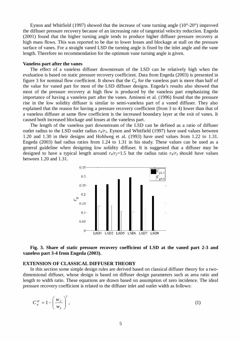
Vaneless part after the vanes The effect of a vaneless diffuser downstream of the LSD can be relatively high when the
evaluation is based on static pressure recovery coefficient. Data from Engeda (2003) is presented in figure 3 for nominal flow coefficient. It shows that the Cp for the vaneless part is more than half of the value for vaned part for most of the LSD diffuser designs. Engeda’s results also showed that most of the pressure recovery at high flow is produced by the vaneless part emphasizing the importance of having a vaneless part after the vanes. Amineni et al. (1996) found that the pressure rise in the low solidity diffuser is similar to semi-vaneless part of a vaned diffuser. They also explained that the reason for having a pressure recovery coefficient (from 3 to 4) lower than that of a vaneless diffuser at same flow coefficient is the increased boundary layer at the exit of vanes. It caused both increased blockage and losses at the vaneless part.
The length of the vaneless part downstream of the LSD can be defined as a ratio of diffuser outlet radius to the LSD outlet radius r4/r3. Eynon and Whitfield (1997) have used values between 1.20 and 1.30 in their designs and Hohlweg et al. (1993) have used values from 1.22 to 1.31. Engeda (2003) had radius ratios from 1.24 to 1.31 in his study. These values can be used as a general guideline when designing low solidity diffuser. It is suggested that a diffuser may be designed to have a typical length around r4/r2=1.5 but the radius ratio r4/r3 should have values between 1.20 and 1.31.
Fig. 3. Share of static pressure recovery coefficient of LSD at the vaned part 2-3 and vaneless part 3-4 from Engeda (2003).
EXTENSION OF CLASSICAL DIFFUSER THEORY In this section some simple design rules are derived based on classical diffuser theory for a two-
dimensional diffuser, whose design is based on diffuser design parameters such as area ratio and length to width ratio. These equations are drawn based on assumption of zero incidence. The ideal pressure recovery coefficient is related to the diffuser inlet and outlet width as follows:
)1(,12
3
'2
wwC id
p
6
In a radial compressor diffuser it is necessary to set up a standard procedure to define the
effective widths of the flow channel, and in this work the effective channel widths w2’ and w3 at diffuser inlet and outlet are defined simply as
)2(,/sin2 '2'2'2 zrw
)3(./sin2 333 zrw
This definition is used as it allows a clear transition between diffusers with overlap of the
blades, where a clearly defined width of the blade passage can be identified, and low solidity diffusers where no overlap may be present. Vane length for a simple flat plate low solidity diffuser is defined as
)4(.90sin
sin
3
'23'2rL
For a straight vaned LSD the outlet flow angle can be defined as a function of radius ratio r2’/r3
and inlet flow angle
3
'2'2
13 90sinsin90
rr . (5)
Diffuser design parameters length to width ratio (LWR) and area ratio (AR) are defined as
2'wLLWR (6)
and
2'
3
wwAR . (7)
RESULTS
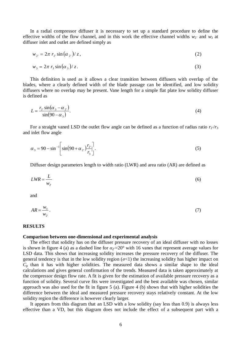
Comparison between one-dimensional and experimental analysis The effect that solidity has on the diffuser pressure recovery of an ideal diffuser with no losses
is shown in figure 4 (a) as a dashed line for 2’=20° with 16 vanes that represent average values for LSD data. This shows that increasing solidity increases the pressure recovery of the diffuser. The general tendency is that in the low solidity region ( <1) the increasing solidity has higher impact on Cp than it has with higher solidities. The measured data shows a similar shape to the ideal calculations and gives general confirmation of the trends. Measured data is taken approximately at the compressor design flow rate. A fit is given for the estimation of available pressure recovery as a function of solidity. Several curve fits were investigated and the best available was chosen, similar approach was also used for the fit in figure 5 (a). Figure 4 (b) shows that with higher solidities the difference between the ideal and measured pressure recovery stays relatively constant. At the low solidity region the difference is however clearly larger.
It appears from this diagram that an LSD with a low solidity (say less than 0.9) is always less effective than a VD, but this diagram does not include the effect of a subsequent part with a
7
vaneless diffuser following the LSD, which improves its performance towards that of the VD. In a way the LSD can be envisaged as a short vane that sets up a suitable flow profile for the subsequent vaneless part, which would otherwise deteriorate strongly with the low flow angles which occur as surge is approached.
(a) (b)
Fig. 4. Effect of solidity on the diffuser pressure recovery (a) and on the ratio of measured and ideal pressure recovery (b).
The explanation for increasing pressure recovery with increasing solidity is given in figure 5 (a),
which shows the variation of Cp as a function of length to width ratio for the same cases as in figure 4 (a). It shows that increasing LWR increases available pressure recovery. Measured values also give confirmation to the calculations and a comparison between measurements and ideal diffuser in figure 5 (b) shows similar trend as figure 4 (b). For a fixed number of vanes, an increase in vane length (and therefore also solidity) leads to higher pressure recovery at the design flow. Also a study of Sorokes and Welch (1992) suggests that a longer vane generates more pressure recovery. These results in figures 4 and 5 indicate that the general performance trend of a low solidity diffuser can be predicted with classical diffuser theory despite of the absence of a geometrical throat. However, it should be noted that the pressure recovery level is too high with 1D theory and the difference between measurement and theory is larger at the low solidity region than it is with larger solidities. A fit is given for the estimation of available pressure recovery as a function of LWR.
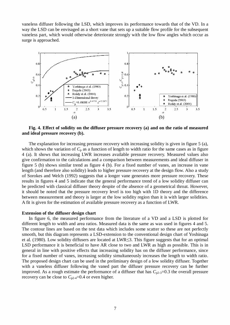
Extension of the diffuser design chart
In figure 6, the measured performance from the literature of a VD and a LSD is plotted for different length to width and area ratios. Measured data is the same as was used in figures 4 and 5. The contour lines are based on the test data which includes some scatter so these are not perfectly smooth, but this diagram represents a LSD-extension to the conventional design chart of Yoshinaga et al. (1980). Low solidity diffusers are located at LWR 3. This figure suggests that for an optimal LSD performance it is beneficial to have AR close to two and LWR as high as possible. This is in general in line with positive effects that increasing solidity has on the diffuser performance, since for a fixed number of vanes, increasing solidity simultaneously increases the length to width ratio. The proposed design chart can be used in the preliminary design of a low solidity diffuser. Together with a vaneless diffuser following the vaned part the diffuser pressure recovery can be further improved. As a rough estimate the performance of a diffuser that has Cp2-3=0.3 the overall pressure recovery can be close to Cp2-4=0.4 or even higher.

8
(a) (b)
Fig.5. Effect of length to width ratio on the diffuser pressure recovery (a) and on the ratio
of measured and ideal pressure recovery (b).
Fig. 6. Contours of Cp2-3 from experimental data of Yoshinaga et al. (1980), Engeda (2003), and Reddy et al. (2004).
CONCLUSIONS A literature review was performed for low solidity diffusers. Available data was collected and
the performance and flow range of low solidity and vaned diffusers was presented proportional to vaneless diffuser. It confirmed the expected effects and gave estimation for the expected efficiency as a function of flow range.
Based on the literature review the following suggestions are made for the design of LSD: Vane shape is not a major parameter affecting the diffuser performance, so that straight
uncambered vanes may be used. The blade inlet angle should be selected to provide a small negative incidence, -2° or
slightly higher should be used. The vane inlet radius ratio r2’/r2=1.1 is a good choice regarding performance and noise. A typical solidity of 0.75 may be used and this determines the vane outlet radius ratio. The blade outlet angle with straight vanes is then a function of the inlet radius ratio, inlet
angle and solidity.

9
The actual pressure rise of a low solidity diffuser with a short radial extent is less than that of a classical vaned diffuser, and there are strong positive effects of having a vaneless part following the vanes especially close to choke conditions. Radius ratio r4/r3 between 1.20 and 1.31 is recommended as a suitable design value.
It was found that increasing the solidity improves the performance of the diffuser. The influence
was high in the low solidity region. The effect of increasing solidity can be explained by the increasing vane length which has been found to be beneficial for the diffuser performance. In general the one-dimensional theory with modifications for LSD reproduces the trends reasonably well but shows a performance shift from the measured data.
A simple method for the preliminary design of low solidity diffuser was developed based on classical diffuser theory and experimental data. It presents a low solidity diffuser extension for a conventional vaned diffuser design chart. This method suggests that for an optimal LSD performance it is beneficial to have area ratio close to two and length to width ratio as high as possible. Together with the proposed vaneless part after the vanes, performance of a diffuser can reach values comparable to vaned diffuser.
As a future work, it would be beneficial to produce additional numerical and experimental data for small length to width ratios that cover more low solidity diffuser designs, as much of the data reported in the literature is confidential. Also the diffuser off-design performance and the effects of blockage, aspect ratio and diffuser width should be studied more in the future together with a validation study of the proposed method. The effects of diffuser vane deviation for the diffuser pressure recovery should be also investigated.
ACKNOWLEDGEMENTS The major part of this paper was conducted during a researcher visit of Dr. Grönman at the
University of Stuttgart. The authors would like to thank Lappeenranta University of Technology for the funding of the visit. The authors would also like to thank Jim Sorokes for his useful comments on an early draft of this paper.
REFERENCES Amineni, N. K., Engeda, A., Hohlweg, W. C. and Direnzi, G. L. (1996). Performance of Low
Solidity and Conventional Diffuser Systems for Centrifugal Compressors. ASME Paper 96-GT-155. Anish, S. and Sitaram, N. (2009). Computational Investigation of Impeller-Diffuser Interaction
in a Centrifugal Compressor with Different Types of Diffusers. Proc. IMechE, Part A: Journal of Power and Energy, Vol. 223, pp. 167-178.
Bonaiuti, D., Amone, A., Hah, C. and Hayami, H. (2002). Development of Secondary Flow Field in a Low Solidity Diffuser in a Transonic Centrifugal Compressor Stage. ASME Paper GT2002-30371.
Engeda, A. (2001). The Design and Performance Results of Simple Flat Plate Low Solidity Vaned Diffusers, Proc. IMechE, Part A: Journal of Power and Energy, Vol. 215, pp. 109-118.
Engeda, A. (2003). Experimental and Numerical Investigation of the Performance of a 240 kW Centrifugal Compressor with Different Diffusers. Experimental Thermal and Fluid Science, Vol. 28, pp. 55-72.
Eynon, P. A. and Whitfield, A. (1997). The Effect of Low-Solidity Vaned Diffusers on the Performance of a Turbocharger Compressor. Proc. IMechE, Part C, Vol. 211, pp. 325-339.
Hayami, H., Senoo, Y. and Utsunomiya, K. (1989). Application of Low-Solidity Cascade Diffuser to Transonic Centrifugal Compressor. ASME Paper 89-GT-66.
Hohlweg, C., Direnzi, G. L. and Aungier, R. H. (1993). Comparison of Conventional and Low Solidity Vaned Diffusers. ASME Paper 93-GT-98.
Issac, J. M., Sitaram, N. and Govardhan, M. (2003). Performance and Wall Static Pressure Measurements on Centrifugal Compressor Diffusers, Proc. IMechE, Part A: Journal of Power and

10
Energy, Vol. 217, pp. 547-558. Kim, Y., Engeda, A., Aungier, R. and Amineni, N. A. (2002). Centrifugal Compressor Stage with
Wide Flow Range Vaned Diffusers and Different Inlet Configurations. Proc. IMechE, Part A: Journal of Power and Energy, Vol. 216, pp. 307-320.
Kmecl, T., ter Harkel, R. and Dalbert, P. (1999). Optimization of a Vaned Diffuser Geometry for Radial Compressor, Part II: Optimization of a Diffuser Vane Profile in Low Solidity Diffusers. ASME Paper 99-GT-434.
Oh, J. and Agrawal, G. L. (2007). Numerical Investigation of Low Solidity Vaned Diffuser Performance in a High-Pressure Centrifugal Compressor, part I: Influence of Vane Solidity. ASME Paper GT2007-27260.
Oh, J., Buckley, C. W. and Agrawal, G. L. Numerical Investigation of Low Solidity Vaned Diffuser Performance in a High-Pressure Centrifugal Compressor, part II: Influence of Vane Stagger. ASME Paper GT2008-50178.
Osborne, C. and Sorokes J. (1988). The Application of Low Solidity Diffusers in Centrifugal Compressors. ASME Conference, Flows in Non Rotating Turbomachinery Components, FED-Vol. 69, pp. 89-101.
Reddy, S. T. C., Ramana Murty, G. V., Mukkavilli, P. and Reddy, D. N. (2004). Effect of the Setting Angle of a Low-Solidity Vaned Diffuser on the Performance of a Centrifugal Compressor Stage. Proc. IMechE, Part A: Journal of Power and Energy, Vol. 218, pp. 637-646.
Reddy, S. T. C., Ramana Murty, G. V., Prasad, M. V. S. S. S. M. and Reddy, D. N. (2007). Experimental Studies on the Effect of Impeller Width on Centrifugal Compressor Stage Performance with Low Solidity Vaned Diffusers. Proc. IMechE, Part A: Journal of Power and Energy, Vol. 221, pp. 519-533.
Sakaguchi, D., Ishida, M., Ueki, H., Hayami, H. and Senoo, Y. (2008). Analysis of Noise Generated by Low Solidity Cascade Diffuser in a Centrifugal Compressor. ASME Paper GT2008-50750.
Senoo, Y. and Kyushu, U. (1984). Low Solidity Cascade Diffusers for Wide Flow Range Centrifugal Blowers. VKI Lecture Series 1984-07.
Sorokes, J. M. and Welch, J. P. (1992). Experimental Results on a Rotatable Low Solidity Vaned Diffuser. ASME Paper 92-GT-19.
Sorokes, J. M. and Koch, J. M. (2000). The Influence of Low Solidity Vaned Diffusers on the Static Pressure Non-Uniformity Caused by a Centrifugal Compressor Discharge Volute. ASME paper 2000-GT-0454.
Turunen-Saaresti, T. (2004). Computational and Experimental Analysis of Flow Field in the Diffusers of Centrifugal Compressors. Acta Universitatis Lappeenrantaensis 192, dissertation, Lappeenranta University of Technology, Finland.
Yoshinaga, Y., Gyobu, I., Mishina, H., Koseki, F. and Nishida, H. (1980). Aerodynamic Performance of a Centrifugal Compressor with Vaned Diffusers. Journal of Fluids Engineering, vol. 102, pp. 486-493.