REVERSE OSMOSIS MEMBRANE ELEMENTS nanoRO and nanoNF …
32
REVERSE OSMOSIS MEMBRANE ELEMENTS nanoRO and nanoNF series TECHNICAL DATASHEET AND OPERATIONAL MANUAL Moscow, 2021 Technical datasheet and operational manual Version: 14 Date of validity: 15.02.21 Document code: OM-2 31 pages
Transcript of REVERSE OSMOSIS MEMBRANE ELEMENTS nanoRO and nanoNF …

REVERSE OSMOSIS MEMBRANE ELEMENTS nanoRO and nanoNF series
TECHNICAL DATASHEET AND
OPERATIONAL MANUAL
Moscow, 2021
Technical datasheet and
operational manual
Version: 14
Date of validity: 15.02.21
Document code: OM-2 31 pages

2
CONTENTS
1. GENERAL PROVISIONS .............................................................................................................. 3
2. DESCRIPTION, THE PRINCIPLE OF OPERATION AND APPLICATION OF SPIRAL
WOUND MEMBRANE ELEMENTS .................................................................................................... 4
3. SHIPPING AND STORAGE .......................................................................................................... 6
4. ACCEPTING AND UNPACKING ITEMS BEFORE USE ........................................................... 8
5. ELEMENTS LOADING IN PRESSURE VESSEL ........................................................................ 9
6. OPERATING PROCEDURES ...................................................................................................... 10
7. CLEANING DURING OPERATION ........................................................................................... 14
8. PRESERVATION OF ELEMENTS IN THE PLANT .................................................................. 22
9. WARRANTY OBLIGATIONS FOR SPIRAL WOUND MEMBRANE ELEMENTS ............... 25
10. EXTENDED WARRANTY OBLIGATIONS FOR SPIRAL WOUND MEMBRANE
ELEMENTS .......................................................................................................................................... 26
11. DISPOSAL OF SPIRAL WOUND MEMBRANE ELEMENTS ................................................. 27
APPENDIX 1 - METHODOLOGY FOR DETERMINING WATER SDI INDEX. ........................... 30
APPENDIX 2 - OPERATION PARAMETERS OF THE DESALINATION PLANT. ...................... 31

3
1. GENERAL PROVISIONS
1.1. This technical datasheet and operational manual (TDS) covers reverse osmosis (RO) and nanofiltration (NF) spiral wound elements produced in accordance with Technical Specification No. 22.29.29-01267318131-2020 (Technical Specification No. 2292-010-67318131-2012), and Technical Specification No. 2292-005-67318131-2012.
Spiral wound membrane elements are designed for application in the reverse osmosis and nanofiltration membrane separation units. This technical datasheet and operational manual sets up rules of storage, installation and operation which compliance provides permanent operational readiness of reverse osmosis and nanofiltration spiral wound membrane elements.
1.2. Elements identification: PP AAA XXYY-ZNMN
1-D
• PP - identification of the spiral wound membrane elements series.
• RO - reverse osmosis membrane elements
• NF - nanofiltration membrane elements
AAA - identification of modification (model, type) of reverse osmosis membranes:
• KM – type of membrane - composite high pressure, high rejection polyamide based. Area of application – sea water desalination.
• KC – type of membrane – composite high rejection polyamide based. Area of application – brackish water desalination. Area of application – brackish water desalination.
• KH - type of membrane – composite low pressure polyamide based. Area of application – brackish water desalination.
• KCH – type of membrane – composite extra low pressure polyamide based. Area of application – brackish water desalination.
• ST - type of membrane - high pressure composite, mechanically reinforced construction.
• SM - type of membrane - composite high pressure.
• SC - type of membrane - composite medium pressure.
• SH - type of membrane - composite low pressure.
XXYY - element sizes:
• XX element diameter (first two symbols) in inches*10.
• YY length of the element (the second two symbols) in inches.
Z - additional information:
• C - fiberglass shell.
• T- polypropylene tape wrapped.
• F - shrink film wrapped.
N - identification of thickness of feed spacer used:
• Number 1* means 28 mil (0.72 mm) thickness of feed spacer.
• Number 2 means 31 mil (0.79 mm) thickness of feed spacer.
• Number 3 means 34 mil (0.86 mm) thickness of feed spacer.
• Number 4 means 46 mil (1.17 mm) thickness of feed spacer. *Number 1 means 26 mil (0.67 mm) thickness of feed spacer for the elements KCH-series
M - identification for the modified element. N
1 - identification for the modification number (1, 2, 3... etc.).)
D - identification for "dry" membrane elements.
4
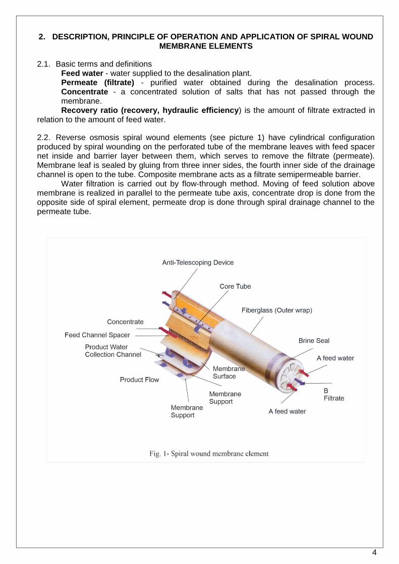
2. DESCRIPTION, PRINCIPLE OF OPERATION AND APPLICATION OF SPIRAL WOUND MEMBRANE ELEMENTS
2.1. Basic terms and definitions Feed water - water supplied to the desalination plant. Permeate (filtrate) - purified water obtained during the desalination process. Concentrate - a concentrated solution of salts that has not passed through the membrane. Recovery ratio (recovery, hydraulic efficiency) is the amount of filtrate extracted in
relation to the amount of feed water.
2.2. Reverse osmosis spiral wound elements (see picture 1) have cylindrical configuration produced by spiral wounding on the perforated tube of the membrane leaves with feed spacer net inside and barrier layer between them, which serves to remove the filtrate (permeate). Membrane leaf is sealed by gluing from three inner sides, the fourth inner side of the drainage channel is open to the tube. Composite membrane acts as a filtrate semipermeable barrier.
Water filtration is carried out by flow-through method. Moving of feed solution above membrane is realized in parallel to the permeate tube axis, concentrate drop is done from the opposite side of spiral element, permeate drop is done through spiral drainage channel to the permeate tube.

5
2.3. Elements fabrication materials, which are in contact with water, do not exude into the water the contaminants in concentration exceeding limits provided in Unified sanitary epidemiological requirements for goods subject to sanitary and epidemiological control, part II section 3 which is confirmed by State Registration certificate No. RU.77.01.34.008.E.003690.04.13 dated 30.04.2013.
2.4. “RM Nanotech” JSC supplies spiral wound elements in dry condition and wet. 2.4.1. Wet membrane elements in preservation solution.
• In a solution containing 2% sodium propionate (for the elements of KC, KCH, SC-series); 1% sodium metabisulfite (for the elements of KM, SM, ST-series); 1 % sodium metabisulfite and 10% propylene glycol (for the elements of KH, SH and NF-series) in order to keep operational characteristics and to prevent microbiological exposure on it.
• Preserved elements are packed in an oxygen barrier film which prevents from oxygen bleeding. Bags are vacuum sealed from both sides in a nitrogen atmosphere. 2.4.2. Dried out membrane elements.
• To preserve the residual moisture, the membrane elements are treated with glycerin solution before drying.
• Non-tested dried out membrane elements are made of membrane flat sheet processed with glycerin which provides presence of residual moisture after drying out.
• Dried out membrane elements are stored in barrier bags.
2.5. Spiral wound membrane elements are designed for the application in the reverse osmosis membrane separation units in the following areas:
• Seawater desalination plants;
• Brackish water desalination up to drinking level in agriculture and public utilities;
• Water treatment plants for heat-power engineering;
• Ultra-pure water production for the products of radio electronics industry;
• Wastewater treatment plants in electroplating industry and extraction of valuable components;
• Technological solutions concentrations in chemical, pharmaceutical, food, metallurgical industries and other sectors of national economy.

6
3. SHIPPING AND STORAGE
3.1. Transportation of items packed in accordance with the technical specifications is carried out by any type of transport in roofed vehicles in accordance with the actual cargo transportation regulations at a temperature from plus 5 °C to plus 40 °C.
3.2. Storage requirements. 3.2.1. New elements should be stored in manufacturer packaging. 3.2.2. Elements packed in accordance with technological specifications should be stored indoor in a dry area at a temperature from + 5°С up to + 35 °С, humidity up to 60% and not in direct sunlight. 3.2.3. Elements should be stored horizontally at the shelves or pallets located not less than 1 meter from the heating elements.
• Elements of size 8040 are stored in no more than nine tiers.
• Elements of size 4040, 2540 are stored in no more than eight tiers.
• For mixed storage of elements of size 4040/2540 on a single pallet, a maximum of 8 tiers is allowed when laying crosswise.
• For mixed storage of elements of size 8040-4040/2540 on one pallet, a maximum of 13 tiers is allowed. 3.2.4. Elements shouldn’t have any impacts of aggressive media, thermal radiation or mechanical stress while storage. 3.2.5. Avoid freezing of the elements and storage temperature more than 35 °С. 3.2.6. During storage, the membrane elements (both dried out and in a preservative solution) must undergo the inspection procedure at least once every three months from the date of shipment from the warehouse of RM Nanotech. 3.2.7. After opening the original packaging, the membrane elements are re-preserved once every three months.
3.3. Carrying out measures for the storage of elements supplied in a preservative solution. 3.3.1. The following procedures should be performed in case of long-term storage (more than 3 months) of the membrane elements.
• Open cardboard box.
• Check the integrity of the barrier film.
• Check vacuum inside barrier film. The element in the packaging barrier bag must be kept under vacuum. The presence of a vacuum is checked by pulling the tail of the barrier package, if the package returns to its original position - the vacuum is present, the barrier package is sealed.
• Carefully inspect the ends of the membrane elements for the presence of dark spots of bio-contamination.
• If damaged packages, packages without vacuum, are detected, the membrane elements should be re-preserved in accordance with clause 3.5.
• Elements with traces of bio-contamination must be isolated and disposed of.
• After the inspection, the items found to be suitable should be packed back in the cardboard box. On the outside of the box, indicate the date of the next inspection.
• After 6 months of storage, the membrane elements according to clause 3.5 should be re-preserved and repackaged.

7
3.4. Carrying out measures for storage of dried out elements. 3.4.1. The following procedures should be performed in case of long-term storage (more than 3 months) of the membrane elements.
• Open cardboard box.
• Check for moisture inside barrier film.
• Carefully inspect the ends of the membrane elements for the presence of dark spots of bio-contamination.
• After the inspection, the items found to be suitable should be packed back in the cardboard box. On the outside of the box, indicate the date of the next inspection.
• Elements that contain moisture at the ends of the elements inside the bag should be re-preserved and repackaged in accordance with clause 3.5.
• Storage period for dry membrane elements reversed into wet is set for not more than 3 months since the date of re-preservation subject to follow cl. 3.2.
3.5. Re-preservation and repackaging of membrane elements. 3.5.1. First, prepare a fresh preservative solution* :
• The elements of the KC, KCH, and SC series are preserved in a 2% solution of sodium propionate.
• Elements of the KH, SH series and elements of the NF series are preserved in a 1% solution of sodium metabisulfite and a 10% solution of propylene glycol.
• The elements of the KM, SM, and ST series are preserved in a 1% solution of sodium metabisulfite. * Special reagents of Membrane Lab series can also be used for preservation. For more information, please contact “RM Nanotech” JSC. 3.5.2. For preparation of preservative solutions, food grade sodium propionate (E281), food grade sodium metabisulfite (E223), propylene glycol (E1520), and desalinated or softened water that does not contain residual chlorine, preferably permeate after reverse osmosis or nanofiltration should be used. 3.5.3. After soaking the elements in the preserving solution for 1 hour, the elements should be removed from the solution, placed vertically for 15 minutes to remove excess solution, and then sealed in bags made of an oxygen-impermeable barrier film. 3.5.4. The items packed in the bags should be put in a cardboard box. On the outside of the box, indicate the date of the next inspection. Packages made of an oxygen-impermeable barrier film can be purchased from the company "RM Nanotech" JSC.

8
4. ACCEPTING AND UNPACKING ITEMS BEFORE USE
4.1. Carefully open the reverse osmosis spiral-wound membrane element packaging cardboard corrugated box in the places indicated on it.
4.2. The element in the corrugated box must be fixed with side seals and equipped with connecting bushings-interconnectors with O-rings. The packaging corrugated box must ensure that there is no damage, dents, or impact marks on the element body.
4.3. The identification number on the cardboard corrugated box must match the number on the element.
4.4. The opening of the packaging barrier bag should be carried out as carefully as possible, so as not to damage the sealing cuff located on one side of the element.
4.5. After opening the barrier bag, it is necessary to inspect the entire surface of the element for the presence of chips, cracks. The anti-telescoping disc must be intact. The core tube should also be free of damage and cracks. The presence of local stains of the preservation solution is allowed. The presence of foreign inclusions is not allowed.

9
5. ELEMENTS LOADING IN PRESSURE VESSEL
5.1. To prepare pressure vessel prior to installation you should remove dust, oil remains, and metal grit and spray it with clean water.
5.2. Check the integrity of the end caps (the cover of the device is a membrane element) and the integrity of the O-rings of the adapters. If necessary, install new end caps or replace the O-rings with new ones.
5.3. Remove the element from the packaging. Make sure that sealing rubbers are in place and there’re no mechanical damages.
5.4. When loading the membrane elements of «RM Nanotech» JSC into the pressure vessels, pay attention to the actual flow of the membrane elements indicated in the passport. Specialists of the technical support center of «RM Nanotech» JSC recommend loading the membrane elements in such a way that at the beginning of the body of the membrane device (on the side of the pressure channel) there are membrane elements with a lower actual capacity, and at the end of the body of the membrane device there are membrane elements with a higher actual capacity. Such arrangement of the membrane elements will allow to organize uniform removal of permeate from each membrane device of the installation.
5.5. Remove the interconnector from the package. The interconnector is used when connecting the membrane elements in series during
loading into multi-seat vessels. When loading one element into a single-seated vessel, the interconnector is not used.
5.6. Lubricate interconnector O-ring seals and brine seals with glycerin. Please note! The use of lubricants based on petroleum products (for example,
silicone) may cause the failure of the membrane elements and may cause the cancellation of warranty obligations.
5.7. Insert the interconnector into the core tube of the membrane element until it stops.
5.8. Gently and without extra efforts load element in pressure vessel ensuring tightness between element and vessel’s wall. Start the elements strictly in the horizontal direction, without vertical distortions.
5.9. You can load successively from 1 up to 3 shrink film wrapped or tape wrapped elements in a pressure vessel (“F” and “T” at the end of element identification) and from 1 up to 8 elements reinforced with fiber glass (“C” at the end of element identification). Meanwhile the core tubes are connected with interconnectors which are supplied with each element.
5.10. Prepare for installation the end caps of the membrane module and special end adapters that connect the core tube of the end elements to the module covers.
Please note! It is forbidden to use the interconnectors as end caps. This may cause feed water leak into permeate and void the warranty.
5.11. Lubricate adapter endcaps sealing rubbers and vessel end caps with glycerin. Install the end caps in the module vessel and fix them. Tightness between the cap and the core tube, as well as between the cap and the module vessel, is ensured by O-rings.
10
6. OPERATING PROCEDURES
6.1. Reliable operation of spiral wound elements is achieved by the appropriate preparation of feed solution and optimized hydrodynamic modes while operation.
6.2. Feed water requirements.
• Turbidity – not more than 1 NTU;
• Oxidation – not more 5 mgО2/l;
• Content of active chlorine, organic solvents and strong oxidizers (ozone, bromine, iodine) – less than 0,1 mg/l;
• Content of dissolved aluminum – less than 0,1 mg/l;
• The content of dissolved iron (II) - less than 4 mg/l (at pH<6, in the presence of oxygen <0,5 mg/l);
• Content of iron (III) – less than 0,1 mg/l;
• Content of manganese – less than 0,1 mg/l;
• Content of cationic polymers and cationic surfactants - less than 0.1 mg / l;
• Content of petroleum products, fats, oils - less than 0.1 mg/l;
• Pollution index (colloidal index, SDI) - less than 5.
• Langelier index (LSI) should not exceed 1.0 when working without anti-scalant and 2.6* when working with anti-scalant (*depending on the anti-scalant, check with the reagent supplier).
Please note! Excess of any parameter can cause warranty cancelation.
6.3. Chemical compatibility with some substances. 6.3.1. Free chlorine and other oxidizers (permanganate, ozone, bromine, iodine) are not allowed in feed water or wash water while reverse osmosis membrane elements operation.
• Even small amount of free chlorine in feed water can cause an irreversible destruction of the membrane selective layer. End-users should be confident that oxidizer doesn’t flow into feed part of the membrane system. In case of the presence of residual free chlorine of more than 0.1 mg/l, dechlorination is necessary.
• Catalysts of membrane oxidization with free chlorine are transition metal ions, such as iron and manganese. If presence of such ions is unavoidable in the water you should take measures to remove 100% of free chlorine from the feed water. 6.3.2. Cationic polymers and cationic surfactants can cause irreversible changes in the properties of composite polyamide membranes. It is not recommended to use these materials during operation and chemical cleaning of the reverse osmosis membrane elements. 6.3.3. Under no circumstances should composite membrane elements be exposed to organic solvents, petroleum products, fats and oils. Any such exposure will cause permanent damage to the membrane. 6.3.4. Glycerin can be used to lubricate the rubber washers. Oil based products application as lubricant can cause membrane elements damage.
Please note! Presence of the indicated materials in the feed water can cause warranty cancelation.
6.4. The first start-up of the unit begins with washing the membrane elements for one hour from a solution of preservative and glycerin. In this case, the substandard permeate and concentrate is discharged into the drainage.
11
6.4.1. If it is intended to use a plant with membrane elements for drinking or food water supply, it is recommended to wash the elements for 1-2 hours.
Please note! Ingestion of preservatives can cause digestive tract irritation, colic, diarrhea, or other similar symptoms. 6.4.2. If the elements are intended to be used for the production of ultrapure water, it is recommended to increase the flushing time of the system to 24 hours to reduce the TOC concentration (total organic carbon content) to 50 micrograms/l (it is assumed that feed water has TOC).
6.5. Measures to prevent the destruction of spiral wound membrane elements:
• Do not exceed the input pressure and input flow above the values specified in the specification.
• Take measures for protection of the membrane elements from the back pressure on the permeate side. The pressure on the permeate side under no circumstances must exceed pressure at the inlet of the membrane element: neither during operation, nor when the plant is switched on/off.
• Permeate valve shall always be open during launch, cleaning, shutdown and standard operation of the reverse osmosis unit. Closing the permeate valve during any phase of the system operation will cause a positive pressure drop between the permeate and concentrate at the tail end of the system and will most likely cause the membrane bags to break along the bonding line at the tail elements.
• Permeate valve can only be closed when the system is switched off after the feed water supply to the system has stopped. When the system is switched on, permeate valve must first be opened before the feed water is supplied, followed by the concentrate valve.
• Сoncentrate valve should be open during launch of the system. The gradual closing of the concentrate valve to create the working pressure and the degree of extraction of the permeate should be started only after the water supply to the system has started.
• During start-up of the reverse osmosis system the feed pressure must be increased up to the operating level gradually within 30-60 second (at the max. rate of 0,1 MPa/sec)
• During shutdown of the reverse osmosis system the feed pressure must be decreased from the operating level to zero gradually within 30-60 seconds (at the max. rate of 0,1 MPa/sec)
• Take measures for prevention of membrane elements’ operation in dead-end mode without concentrate discharge.
• Avoid hydraulic hammer during start-up, operation and shutdown of reverse osmosis systems.
• Feed water and permeate tests should be conducted during operation. Please note! Violations of the above requirements for the control of the permeate
and concentrate valve can cause warranty cancellation.
• For reverse osmosis and nanofiltration plants designed for treatment of surface and underground sources with solid contents of feed water up to 5 g/l, it is necessary to conduct a hydraulic flushing of the membrane elements with feed water having a low degree of permeate extraction before complete stop of the system. To do this, the concentrate adjustment valve is usually slightly open, which allows the highly concentrated saline solution to be removed from the membrane elements. Feed water supply per one inlet membrane element should not exceed 17 m3/hr for elements type 8040 and 3.5 m3/hr for type elements 4040, in order to avoid mechanical damage to the elements due to telescoping. Permeate outlet must be open.
• For systems intended for desalination of saline sources with solid contents of feed water of more than 5 g/l, before stopping the system, it is necessary

12
to conduct hydraulic flushing of membrane elements with permeate (desalinated water) with a low degree of filtrate extraction before stop of the system. Feed water supply per one inlet membrane element should not exceed 17 m3/hr for elements type 8040 and 3.5 m3/hr for type elements 4040, in order to avoid mechanical damage to the elements due to telescoping. Permeate outlet must be open.
• Seawater desalination systems should not be left unwashed under any circumstances due to the risk of rupture of the membrane packages as a result of osmotic pressure generated by the permeate when the system is stopped, as well as the high probability of scaling on the surface of membrane elements.
6.6. Operating conditions. 6.6.1. The permeate recovery rate (PRR) on each 1 m (40 in) long membrane element should not exceed 15 % for the elements of KC, KH, KCH, SC, SH, NF series. 6.6.2. PRR for the elements of KM, SM, ST series should not be higher than 10 %. For long-term and stable operation of marine reverse osmosis plants, it is recommended to maintain PRR on each 1 m long membrane element within the range of 6-8 %. 6.6.3. The operating pressure may vary depending on the type of membrane elements, solid contents of feed water, temperature, degree of filtrate extraction, and service life of membrane elements: 6.6.4. Pressure drop should not exceed 0.07-0.1 MPa (depending on the type of spiral wound membrane element) on each element and 0.35 MPa on each membrane pressure vessel of 6 elements. 6.6.5. Feed water temperature must not exceed 45 °С. At рН higher than 10.5 maximum temperature of feed water must not exceed 35 °С. 6.6.6. Chemical washings of spiral wound membrane elements are carried out in the pH range of 1÷13*, depending on the type of detergent compositions. At the same time, chemical cleaning frequency shouldn’t exceed one time per month. Otherwise parameters of the pretreatment should be changed before installation. *When conducting chemichal washing with a pH of the flushing solution above 11.5, contact the manufacturer of the membrane elements for advice. 6.6.7. Maximum turbidity of feed water should not be more than 1 NTU, and SDI <5. For long-term and stable operation of the plants, it is recommended to carry on the pretreatment of feed water to a turbidity of less than 0.2 NTU and SDI to a level of 1-3.
6.7. Passport flow rate measurement of membrane elements and temperature compensation. 6.7.1. Nominal capacity of membrane elements is calculated at operating pressure and feed water temperature of 25 ± 2 °C. 6.7.2. When the temperature of feed water decreases, the flow of the membrane element decreases also. For correct processing of the results and the possibility of comparison, it is necessary to bring all the parameters of the plant to the normalized equal conditions.
The values of the correction factor (K) for calculating the flow of membrane element depending on feed water temperature are shown in Table 1.

13
Table 1 - Correction factor of offset temperature t, oC Кт t, oC Кт t, oC Кт t, oC Кт
10.0 1.71 15.0 1.42 20.0 1.19 25.0 1.00
10.5 1.68 15.5 1.40 20.5 1.17 25.5 0.98
11.0 1.65 16.0 1.37 21.0 1.15 26.0 0.97 11.5 1.62 16.5 1.35 21.5 1.13 26.5 0.96 12.0 1.59 17.0 1.32 22.0 1.11 27.0 0.94
12.5 1.56 17.5 1.30 22.5 1.09 27.5 0.93
13.0 1.53 18.0 1.28 23.0 1.07 28.0 0.92 13.5 1.50 18.5 1.25 23.5 1.05 28.5 0.90
14.0 1.48 19.0 1.23 24.0 1.03 29.0 0.89 14.5 1.45 19.5 1.21 24.5 1.02 29.5 0.88
Flow of the membrane element (Qt) while given temperature (t) is counted according to the formula:
Qt=Q25 /Kt,
which means that while temperature decreasing from 25°С down to 10°С, the flow of the membrane element will go down by 1.71 times (see Table 1).
If normalized recovery rate of the membrane unit is reduced by more than 1.15 times compared to the passport specification data (after 48 hours from the start-up), it is necessary to perform a chemical washing of membrane elements (see paragraph 7.4)
For example: Flow rate of the plant after 48 hours of operation at a temperature of 20 °C was Q120 = 10m3/ hr. The
normalized permeate flow (in terms of feed water temperature of 25°C, see Table 1) will be Q125 = Q120 *K = 10*1.19=11.9m
3/ hr
After 2 months of operation at a source water temperature of 10 °C and the same operating pressure on the membrane unit, the productivity was Q210 =6m
3/ hr.
We calculate the capacity of the plant in terms of feed water temperature of 25 °C, i.e.
Q225 = Q210 *K= 6*1.71=10.26m3/ hr,
where K=1.71(from Table 1). Thus, the drop in plant flow rate, adjusted for the temperature of feed water at a constant operating pressure, occurred
in 11.9/10.26 = 1.16 times, i.e. it is necessary to carry out chemical washing of the membrane elements.

14
7. CLEANING DURING OPERATION
7.1. This section provides general information on common contaminants that affect the flow rate of membrane elements and methods for their removal. This information applies to membrane elements with the diameter of 2.5, 4.0, 8.0 inches.
Note: It is recommended to carry out all membrane cleaning operations in coordination with the specialists of the technical center of "RM Nanotech" JSC during the warranty period for the elements. If necessary, the company's specialists go to the site to assist in cleaning the membranes. Please contact the company for payment for the services of these specialists.
7.2. Contamination of membranes. 7.2.1. Over time, during normal operation, membrane elements are contaminated with suspended or slightly soluble substances that may be present in feed water.
The nature and rate of deposits on the surface of a membrane depend on the state of feed water. Membrane contamination is a progressive phenomenon, and if it is not controlled at an early stage, it will negatively affect the flow rate of membrane elements in a relatively short period.
The most common substances that can be deposited on the surface of membrane elements are: calcium carbonate, calcium sulfate, metal oxides, silica, organic or biological deposits. 7.2.2. Regular monitoring of the plant operation is a prerequisite for detecting contamination of the membranes.
In the absence of timely washing of membrane elements, the efficiency of removing dirt from the surface of membranes decreases. 7.2.3. The effect on the flow rate and rejection of the membranes is gradual, it varies depending on the nature of the contaminant. 7.2.4. To determine the type of spiral wound membrane element contamination, you can do the following:
• Analysis of feed water. It is possible that some quality indicator is exceeded.
• Analysis of deposit composition on the cartridge filter.
• Analysis of filter residues formed during the determination of SDI of water before desalination plant.
• Analysis of consistency and color of the sediment on the membrane or filter to determine SDI:
- Brown color is usually due to the presence of excess iron in the water. - White or beige color is usually caused by compounds of silicon, organic matter or
calcium. - Dense crystalline precipitate is usually caused by hardness salts or inorganic colloids. - Sediment, which has a sticky, slimy consistency, is usually due to the organic or
biological nature of the contamination.
• Analysis of changes in hydraulic characteristics in accordance with Table 2.
7.3. The main common contaminants and cleaning solutions for their removal are listed in Table 3.

15
Table 2 - Signs of RO membrane elements contamination
№ Potential reason Possible location
Pressure drop Operating pressure
Permeate electrical
conductivity
1 Metal oxides (Fe, Mn, Cu,
Ni, Zn) 1 cascade
Increases rapidly
Increases rapidly
Increases rapidly
2 Colloidal contamination
(organic and / or inorganic complexes)
1 cascade Increases gradually
Increases gradually
Increases slightly
3 Mineral contamination (Ca,
Mg, Ba, Sr) The last cascade
Increases moderately
Uptick Increases
greatly
4 Polymerized silicon dioxide The last cascade
Normal or increases
Increases Normal or increases
5 Biological pollution All stages, usually 1
High magnification
High magnification
Normal or increases
6 Organic pollution (dissolved
organic matter) All stages
Increases gradually
Increases Lowering
7 Contamination due to an
improperly functioning inhibitor (anti-scalant)
Greater development on the last cascade
Normal or increases
Normal or increases
Increases
8 Contamination with an inhibitor (anti-scalant)
Greater development on the last cascade
Normal or increases
Increases Normal or increases
9 Oxidizer (Cl, KMnO4, ozone) Greater
development on the 1st cascade
Normal or increases
Decreases Increases
10 Hydrolysis (outside the pH
range) All stages
Normal or increases
Decreases Increases
11 Abrasive damage Greater
development on the 1st cascade
Normal or increases
Decreases Increases
12 Damage to the O-ring
(interconnectors or adapters)
All stages. Usually on feed water adapters.
Normal or increases
Normal or increases
Increases
13
Destruction of the adhesive joint (for example, due to the
back pressure of the permeate in maintenance or
backup mode)
Greater development on the 1st cascade
Normal or decreasing
Normal or decreasing
Increases
14
Destruction of the adhesive joint (for example, due to the
closed permeate valve during washing)
Last elements Increases Increases Increases

Table 3 - Types of contamination and cleaning solutions Type of contamination Solution characteristics Solution Concentration,%
Precipitation of calcium (carbonates and phosphates)
Preferably Membranium LAB-494 4-6
Preferably Hydrochloric acid 0.2
Preferably Citric acid 2-4
Alternative option Phosphoric acid 0.5
Calcium, Barium, Strontium sulfate
Preferably Membranium LAB-482 2,5-4
Preferably Membranium LAB-468 2-3
Preferably Sodium hydroxide 0.1
Trilon B 1
Preferably Sodium Tripolyphosphate 2
Trilon B 1
Hydrated oxides (iron, nickel, copper, etc.)
Preferably Membranium LAB-494 4-6
Preferably Hydrochloric acid 0.2
Preferably Citric acid 2-4
Alternative option Phosphoric acid 0.5
Alternative option Sulfamic acid 1
Silicon (silicon-organic)
Preferably Membranium LAB-482 2,5-4
Preferably Membranium LAB-483 1-2
Preferably Sodium hydroxide 0.1
SLS 0.025
Alternative option Sodium hydroxide 0.1
Alternative option Sodium hydroxide 0.1
Trilon B 1
Mixed organic / inorganic colloids (iron, organic substances)
Preferably Membranium LAB-482 2,5-4
Preferably Membranium LAB-483 1-2
Preferably Membranium LAB-468 2-3
Preferably Sodium hydroxide 0.1
SLS 0.025
Preferably Sodium Tripolyphosphate 2
Trilon B 1
Alternative option Sodium Tripolyphosphate 2
SLS 0.025
Alternative option Sodium hydroxide 0.1
SLS 0.025

Table 3 - Types of contamination and cleaning solutions Type of contamination Solution characteristics Solution Concentration,%
Organic deposits
Preferably Membranium LAB-482 2,5-4
Preferably Membranium LAB-483 1-2
Preferably Membranium LAB-468 2-3
Preferably Sodium hydroxide 0.1
Preferably Sodium hydroxide 0.1
SLS 0.025
Alternative option Sodium hydroxide 0.1
Trilon B 1
Alternative option Sodium Tripolyphosphate 2
Trilon B 1
Alternative option Sodium Tripolyphosphate 2
SLS 0.025
Bacteriological contamination
Preferably Membranium LAB-482 2,5-4
Preferably Membranium LAB-483 1-2
Preferably Membranium LAB-468 2-3
Preferably Membranium LAB-471 0.5
Preferably Membranium LAB-473/473C4 0.5
Preferably Sodium hydroxide 0.1
Preferably Sodium hydroxide 0.1
SLS 0.025
Alternative option Sodium hydroxide 0.1
Trilon B 1
SLS-Sodium Lauryl Sulfate Mix solutions extensively before use. рН-meter should be regularly gauged. The typical time for chemical washing with each solution,
depending on the temperature, is from 30 minutes to 4 hours (if you need to increase the washing time, you should consult the Technical Support Center of "RM Nanotech" JSC).
*In addition to the specified cleaning solutions, special cleaning solutions for composite membrane elements may be allowed for chemical washing after approval by "RM Nanotech" JSC.

18
7.4. Conditions** for the removal of membrane elements for washing
• Normalized (reduced to 25 °C, see point 6.7.2.) permeate flow decreased by 15% compared to the starting* value.
• Normalized value of the electrical conductivity of the filtrate increased by 15% (the normalized salt passage increased by 15 %) compared to the starting* value.
• The normalized pressure drop (the difference between the initial pressure and the concentrate pressure - ΔР) at the plant at a constant flow rate of feed water and PRR increased by 15% compared to the starting* value. It is desirable to monitor the ΔР after each cascade at each stage of the installation.
* The initial starting values are determined in the first 48 hours after starting the unit. ** The operating parameters of the plant must be continuously recorded in accordance with Annex 2 of this manual and must be available to "RM Nanotech" JSC in the event that it is sued for compensation in accordance with this warranty.
Please note! Exceeding these parameters during operation can cause warranty cancellation.
7.5. Flushing requirements 7.5.1. The frequency of chemical flushing of membrane elements usually does not exceed one time per month (except for elements used for wastewater treatment, or used in food and dairy industries). If more frequent flushing is required, you must change the pre-cleaning parameters before installation or the operating conditions.
Please note! Violations of the above requirements for the frequency of chemical washes can cause warranty cancellation. 7.5.2. When performing chemical washing, it is advisable to wash each cascade and each stage of the installation separately. Sequential washing of the cascades is undesirable, since it is possible that the flow rate of the cleaning reagent is unevenly distributed over the cascade vessels, as well as contamination of feed water supply pipelines of the subsequent cascades with deposits from the previous one. 7.5.3. Before washing, it is necessary to choose the right composition of cleaning solutions, depending on the type of contamination. If the reagents are not selected correctly, the contamination of the membranes may increase. Identification of the main type of contamination and selection of the correct detergent compositions is carried out according to Table 3.
7.6. Standard procedure for washing membrane elements. 7.6.1. Mandatory conditions for washing:
• During chemical washing, the concentrate and permeate valves must be fully open.
• The flow of the cleaning solution is fed to the plant from feed water side in the filtration mode. It is STRICTLY FORBIDDEN to flush the membrane elements in the opposite direction due to the structural features of the elements (the location of seals). 7.6.2. Stages of flushing: Flushing of pressure vessels by pumping demineralized (free of chlorine or other oxidizing agents) water heated to 25-45 °C* (*see Table.5) from the chemical wash tank (or equivalent source) for a few minutes.
7.6.2.1. Preparation of a cleaning solution on demineralized water in a chemical wash tank. The amount of cleaning solution (Table 4) per one membrane element is determined by the number and dimensions of membranes. This volume does not include

19
the volume of the solution required to displace feed water, fill supply pipelines, filters, etc.
Table 4-Volume of cleaning solutions per one membrane element
Size of a membrane element Volume of cleaning solution, l
2540 3-5
4040 10-20
8040 40-80
7.6.2.2. Recommended parameters for chemical washings are given in Table 5.
Table 5-Acceptable conditions for chemical washings
PH value for different temperature ranges of cleaning solutions
up to 25 °C 26-35 °C 36-45 * °C
1-13* 1-13* 2-11
*When conducting chemical washing with a pH of the washing solution above 11.5 or at a solution temperature of more than 45 °C, contact the manufacturer of the membrane elements for advice.
7.6.2.3. Displacement of feed water from membrane pressure vessels and pipelines. Finished cleaning solution is passed through pressure vessels with a low flow rate (equal
to about half the speed indicated in Table 6) and low pressure. In this case, the source water and the first portions of cleaning solution (approximately 20% of the initial volume) are drained so as not to dilute the cleaning solution in the tank and prevent its salvo contamination.
7.6.2.4. High-flow detergent solution circulation. The cleaning solution is circulated through the high-flow pressure vessels for approximately
1 hour or within the required time for each cascade, with the permeate and concentrate returning to the chemical wash tank.
Recommended cleaning solution flow rates per one pressure housing and flow pressure are shown in Table 6.
Table 6-Recommended feed flow rates and cleaning solution pressure per 1 vessel
Size of a membrane element Flow rate*,m3/ h Pressure of the initial flow of
the cleaning solution, bar
2540 0,7-1,2 1,5-4
4040 2-2,5 1,5-4
8040 7-9 1,5-4

20
* The speed increases in proportion to the number of vessels within one cascade. For example: A plant with 8040 size elements has two cascades for concentrate, connected according to the scheme:
3 vessels on the first cascade and 2 vessels on the second (each vessel has 6 elements). When each cascade is washed separately, the solution is fed to the input of the first cascade at speedsof 21-27 m
3/
hr, and to the second cascade at speeds of 14-18m3/h.
When two cascades are washed in sequence, the solution is immediately fed to the inlet of the plant at a speed of 14-18 m
3/ hr (based on the permissible speed of the second cascade).
During circulation, it is necessary to monitor: • pH of the cleaning solution. If pH changes by more than 0.5 units, it is necessary to re-
bring it to the normalized value with an alkali/acid solution. • The temperature. It is necessary to maintain the temperature of the cleaning solution in
accordance with Table 5. • Colour of the cleaning solution. If the solution becomes dark or dirty during the washing
process, then it is necessary to drain it and prepare a new one, according to clause 7.6.2.1.

21
7.6.2.5. Soaking. Soaking the membranes in the cleaning solution for 1 hour (or for the required time) with
periodic circulation of the cleaning solution with a low flow rate to maintain the temperature of the solution in the installation.
7.6.2.6. High-flow detergent solution recirculation. Circulation of the washing flow rate in accordance with the conditions of clause 7.6.2.4.
7.6.2.7. Washing of membrane elements with demineralized water It is necessary to drain the cleaning solution from the chemical washing tank and rinse the
container with demineralized water. Fill the cleaned tank with demineralized water and heat it to a temperature of at least 20 °C
(if possible). Start pumping demineralized water through the unit with the discharge of permeate and
concentrate into the drainage (at least for 30 minutes). Washing is carried out to the pH +/- 1 pH of the permeate.
7.6.2.8. Enabling the unit to work After washing, the unit must be put into operation. The first portions of the permeate and
concentrate are drained. The unit is put into normal operation only after the permeate quality has been achieved
according to the user's requirements.
7.7. It may take several hours to stabilize the operating parameters of the unit after flushing. After the alkaline washing, it may take several days to stabilize the parameters.
7.8. In the absence of restoration of the characteristics of the plant, it is necessary to repeat the washing procedure.
7.9. In case of problems related to washing, it is necessary to contact the technical support center of "RM Nanotech" JSC for assistance.

22
8. PRESERVATION OF ELEMENTS IN THE PLANT
8.1. After use, membrane elements must be stored in wet condition.
8.2. If membrane system is shut down for more than 48 hours, spiral wound membrane elements preservation should be applied. For short stops, we recommend the usual cleaning procedure.
8.3. Before carrying out the preservation procedure in the system a complex alkaline-acid washing and washing with demineralized water of the membrane elements in accordance with paragraph 7should be carried out.
8.4. The preservation procedure should be performed immediately after cleaning and disinfection process, the maximum time between cleaning/disinfection and preservation periods should not be more than 12 hours.
8.5. Preservation is carried out by recirculating a 1 % solution of sodium metabisulfite, using a chemical wash unit. The solution should be circulated through the system for about 1 hour. During preservation, make sure that the system is airless and impervious to outside air.
8.6. Close all taps/valves on the plant after preservation.
8.7. The preserved membrane system should be periodically monitored for pH. The pH value should not be less than 3. If the pH value falls below 3, the preservative solution should be replaced. The preservative solution should be changed at least once every 3 months.
8.8. During inaction periods of the plant, the maximum temperature should not exceed 35 °C, but should not be less than 4 °C. Optimal storage temperature: 5÷15 °С.
8.9. When resuming operation of the unit, it should be washed from the preservative for at least 1 hour.
23
an initial
9. WARRANTY OBLIGATIONS FOR SPIRAL WOUND MEMBRANE ELEMENTS
9.1.1. "RM Nanotech" JSC provides a one-year limited warranty for the RO, NF series of spiral wound membrane elements.
9.1.2. "RM Nanotech" JSC provides warranty for the materials, manufacturing quality and operation of its spiral wound membrane elements1, in compliance with the requirements of the operating instructions, as well as in compliance with the recommendations of "RM Nanotech" JSC in accordance with the following provisions.
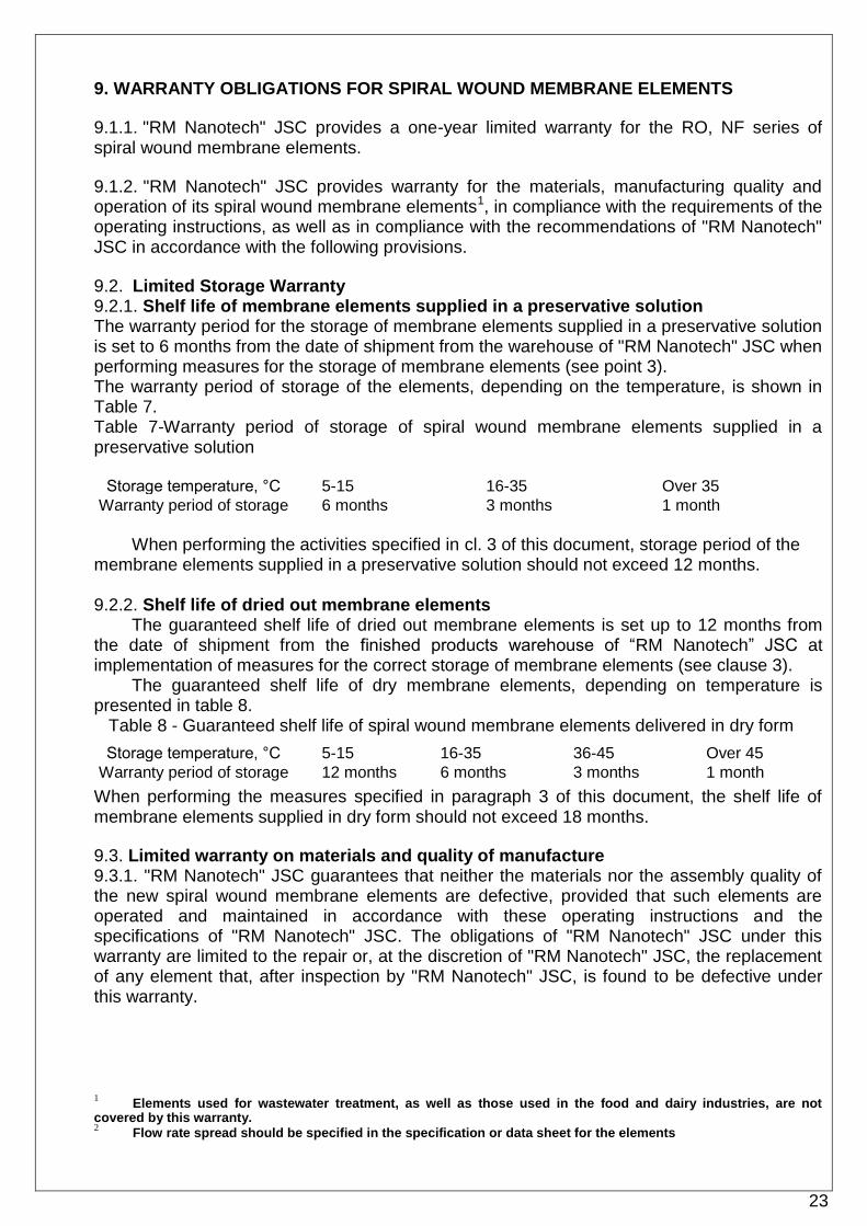
9.2. Limited Storage Warranty 9.2.1. Shelf life of membrane elements supplied in a preservative solution The warranty period for the storage of membrane elements supplied in a preservative solution is set to 6 months from the date of shipment from the warehouse of "RM Nanotech" JSC when performing measures for the storage of membrane elements (see point 3). The warranty period of storage of the elements, depending on the temperature, is shown in Table 7. Table 7-Warranty period of storage of spiral wound membrane elements supplied in a preservative solution
Storage temperature, °C 5-15 16-35 Over 35
Warranty period of storage 6 months 3 months 1 month
When performing the activities specified in cl. 3 of this document, storage period of the
membrane elements supplied in a preservative solution should not exceed 12 months. 9.2.2. Shelf life of dried out membrane elements
The guaranteed shelf life of dried out membrane elements is set up to 12 months from the date of shipment from the finished products warehouse of “RM Nanotech” JSC at implementation of measures for the correct storage of membrane elements (see clause 3).
The guaranteed shelf life of dry membrane elements, depending on temperature is presented in table 8.
Table 8 - Guaranteed shelf life of spiral wound membrane elements delivered in dry form
Storage temperature, °C 5-15 16-35 36-45 Over 45
Warranty period of storage 12 months 6 months 3 months 1 month
When performing the measures specified in paragraph 3 of this document, the shelf life of membrane elements supplied in dry form should not exceed 18 months.
9.3. Limited warranty on materials and quality of manufacture 9.3.1. "RM Nanotech" JSC guarantees that neither the materials nor the assembly quality of the new spiral wound membrane elements are defective, provided that such elements are operated and maintained in accordance with these operating instructions and the specifications of "RM Nanotech" JSC. The obligations of "RM Nanotech" JSC under this warranty are limited to the repair or, at the discretion of "RM Nanotech" JSC, the replacement of any element that, after inspection by "RM Nanotech" JSC, is found to be defective under this warranty.
1 Elements used for wastewater treatment, as well as those used in the food and dairy industries, are not covered by this warranty. 2 Flow rate spread should be specified in the specification or data sheet for the elements

24
9.3.2. "RM Nanotech" JSC guarantees that the elements supplied to the Buyer have an initial minimum permeate consumption and an initial minimum rejection in accordance with the data specified in the catalogues and passports for membrane elements.
These parameters are set in the course of standard tests established in "RM Nanotech" JSC.
9.3.2.1. Reverse osmosis elements:
• The flow rate of each element in a batch may vary by ±15 %2
• The nominal rejection of dried out membrane elements, size 1812, 2521, 2540, is achieved after 100 hours of continuous operation on the test solution.
• The nominal rejection of dried out membrane elements, size 4040 and 8040, is achieved after 48 hours of continuous operation on the test solution.
• The nominal rejection of membrane elements supplied in the preservative solution of sizes 2540, 4040 and 8040 is achieved after 2 hours of continuous operation on the test solution.
9.3.2.2. Nanofiltration elements:
• The flow rate of each element in the batch may vary by ±20 %2
• The nominal rejection of dried out membrane elements is achieved after 100 hours of continuous operation on the test solution.
• The nominal rejection of membrane elements supplied in preservation solution is achieved after 48 hours of continuous operation on the test solution.
9.4. Terms of compliance with the limited annual warranty 9.4.1. In compliance with these operating instructions, "RM Nanotech" JSC guarantees the operation of its elements for 12 months from the start of operation, provided that the new elements were put into operation no later than 6 months after the date of shipment from the warehouse of "RM Nanotech" JSC. 9.4.2. The limited one-year warranty will be cancelled if one of the following conditions of clause 9.5 is not met.
9.5. Operation during the one-year limited warranty 9.5.1. The Buyer is responsible for the safety of spiral wound membrane elements during transportation, storage, and installation in pressure vessels. Failure to comply with the conditions of transportation, storage and installation of spiral wound membrane elements in pressure vessels (see p. 3-p. 5) may cause cancellation of manufacturer's warranty obligations. 9.5.2. The Buyer is responsible for providing Users with appropriate operating instructions for the system, training operators and maintenance personnel, and ensuring that proper cleaning and diagnostic procedures are possible. 9.5.3. At the first start-up, the element should be washed for at least 1 hour from the preservative. According to the results of washing, an appropriate report should be drawn up. After two hours of operation of the membrane plant, the first record of all the parameters of the plant (inlet pressure, concentrate and permeate pressure, pressure drop in the unit at each stage, flow rate of feed water, permeate, concentrate, as well as the analysis of feed water and permeate) should be done in the operating log of the membrane unit. All initial parameters of the membrane system must be sent to the manufacturer of the membrane elements. The absence of the specified data at the first start of the installation may be the reason for the refusal of the manufacturer's warranty obligations. 9.5.4. The buyer must ensure that the operating characteristics of the system, in accordance with paragraph 6 and paragraph 7 of this manual, are regularly recorded and systematically analyzed. This information should be available to

25
"RM Nanotech" JSC in the event that it is sued for compensation in accordance with this warranty. 9.5.5. The quality of feed water, the reagents used, and the working conditions must meet the requirements of the operating instructions. 9.5.6. The buyer is responsible for the use of chemicals that are not recommended for use with membrane elements. 9.5.7. If the consumer ignores the recommendations for the operation of the membrane elements, this may cause cancellation of manufacturer's warranty obligations.
9.6. Repair or replacement 9.6.1. Should warranty event arise, "RM Nanotech" JSC undertakes to replace the damaged element with a new one. 9.6.2. "RM Nanotech" JSC reserves the right to check suspected defective elements and systems at the User's factory or to request the Buyer to conduct tests and send the results to "RM Nanotech" JSC. If, during the inspection of the membrane element at the Buyer's factory, it turns out that it is damaged for a reason other than those specified in the warranty, the Buyer must make a payment to "RM Nanotech" JSC in the amount of 50,000 rubles, as well as pay the costs incurred by the employees of "RM Nanotech" JSC in connection with any inspection and testing of such elements and systems at the Buyer's factory, including, but not limited to, travel and transportation costs. 9.6.3. Before returning the membrane element for inspection under warranty, the Customer must obtain consent for the return of the elements. 9.6.4. Delivery of the returned membrane elements is paid by the sender, and "RM Nanotech" JSC assumes the cost of delivery to the customer of the membrane elements replaced under the warranty. At all times, the membranes must be kept in wet condition and clean, and they must be placed in a waterproof package before being returned. 9.6.5. Membrane elements can be returned within 90 days from the date of shipment from the warehouse of "RM Nanotech" JSC, only if they have not been used and are in the original factory packaging. Otherwise, the refund may be refused or an additional payment for the restoration of the saleable condition may be required.
9.7. Warranty warning 9.7.1. Failure to provide "RM Nanotech" JSC with open access to the operating parameters of the system in which membrane elements of "RM Nanotech" JSC are installed will result in complete cancellation of warranty obligations, except for those that apply to materials and components.
26
10. EXTENDED WARRANTY OBLIGATIONS FOR SPIRAL WOUND MEMBRANE ELEMENTS
10.1.1. "RM Nanotech" JSC provides a three-year limited warranty for spiral wound membrane elements of RO, NF series.
10.1.2. "RM Nanotech" JSC provides warranty for the materials, manufacturing quality and operation of its spiral wound membrane elements1, in compliance with the requirements of the operating instructions, as well as in compliance with the recommendations of "RM Nanotech" JSC in accordance with the following provisions.
10.2. The limited warranty for storage, materials and workmanship is in accordance with clause 9. 2-9. 3 of this document.
10.3. The terms of repair and replacement, as well as warranty warning, comply with paragraphs 9.6-9.7 of this document.
10.4. Terms of compliance with limited three-year warranty 10.4.1. In compliance with these operating instructions, "RM Nanotech" JSC guarantees the operation of its elements for 3 years from the start of operation, provided that the new elements were put into operation no later than 6 months after the date of shipment from the warehouse of "RM Nanotech" JSC. 10.4.2. During the first three years of operation of the elements, "RM Nanotech" JSC guarantees that the minimum permeate consumption, when operating under standard conditions, should be at least 70 percent of the initial average flow rate. 10.4.3. "RM Nanotech" JSC also guarantees that the maximum value of salt transmission of the elements will not exceed 35% of the initial maximum value under standard test conditions. 10.4.4. The limited three-year warranty will be cancelled if one of the following conditions of clause 9.5 is not met.
10.5. Operation during three-year limited warranty 10.5.1. The Buyer is responsible for the safety of spiral wound membrane elements during transportation, storage, and installation in pressure vessels. Failure to comply with the conditions of transportation, storage and installation of spiral wound membrane elements in pressure vessels (see p. 3-p. 5) may cause cancellation of manufacturer's warranty obligations. 10.5.2. The Buyer is responsible for providing Users with appropriate operating instructions for the system, training operators and maintenance personnel, and ensuring that proper cleaning and diagnostic procedures are possible. 10.5.3. At the first start-up, the element should be washed for at least 1 hour from the preservative. According to the results of washing, an appropriate report should be drawn up. After two hours of operation of the membrane plant, the first record of all the parameters of the plant (inlet pressure, concentrate and permeate pressure, pressure drop in the unit at each stage, flow rate of feed water, permeate, concentrate, as well as the analysis of feed water and permeate) should be done in the operating log of the membrane unit. All initial parameters of the membrane system must be sent to the manufacturer of the membrane elements. The absence of the specified data at the first start of the installation may be the reason for the refusal of the manufacturer's warranty obligations. 10.5.4. The buyer must ensure that the operating characteristics of the system, in accordance with paragraph 6 and paragraph 7 of this manual, are regularly recorded and systematically analyzed. This information should be available to "RM Nanotech" JSC in the event that it is sued for compensation in accordance with this warranty.

27
10.5.5. The quality of feed water, the reagents used, and the working conditions must meet the requirements of the operating instructions. 10.5.6. Chemical washing of the elements must be carried out in strict accordance with the instructions of "RM Nanotech" JSC, described in the operating instructions: with Membrane Lab reagents or reagents that have an expired certificate of "RM Nanotech" JSC. The buyer is responsible for the use of chemicals that are not recommended for use with membrane elements. 10.5.7. If the consumer ignores the recommendations for the operation of the membrane elements, this may cause cancellation of manufacturer's warranty obligations.
28
11. DISPOSAL OF SPIRAL WOUND MEMBRANE ELEMENTS
11.1. Users are responsible for the disposal of membrane elements manufactured by "RM Nanotech" JSC in accordance with all local and federal regulations. Waste hazard class - 4.
11.2. Used membrane elements manufactured by "RM Nanotech" JSC can be disposed of as household waste, provided that the free liquid or hazardous substances contained in them do not exceed the permissible threshold.
"RM Nanotech" JSC Russia 600031 Vladimir Dobroselskaya st. 224 D
tel. / fax. +7 (4922) 47-40-01 www.membranium.com

29
APPENDIX 1 - METHODOLOGY FOR DETERMINING WATER SDI INDEX
1. Required equipment: 1.1 Membrane filter with a pore size of 0.45 microns and a diameter of 47 mm; 1.2. Filter holder for membrane filter with a diameter of 47 mm; 1.3. Stopwatch; 1.4. Graduated container of 500 ml capacity; 1.5. Thermometer for measuring the temperature of water sample; 1.6. Pressure maintenance system of 2.5-3.0 bar with necessary equipment (valves, pressure gauges, gearboxes, etc.).
2. Equipment requirements: 2.1. Microfilter requirements: 2.1.1. Membrane - flat, white, hydrophilic, material: mixture of cellulose acetates; 2.1.2. Average pore size is 0.45±0.02 microns; 2.1.3. Nominal diameter — 47 mm; 2.1.4. Thickness — 115-180 microns; 2.1.5. Time to pass 500 ml of pure water through a 47 mm diameter membrane:
25÷50 seconds (specific capacity of the membrane: 35÷70 ml/(min * cm2); pressure: 91.4 ÷94.7 kPa); 2.1.6. Bubble point — 179÷248 kPa; 2.2. Requirements to the rest of the equipment: 2.2.1. All connecting elements must be made of plastic or stainless steel to prevent corrosion; 2.2.2. The pump must provide an outlet pressure of up to 0.35÷0.4 MPa without pulsation; 2.2.3. The filter holder must withstand a pressure of up to 0.35÷0.4 MPa.
3. Description. This technique describes a method for determining the SDI index of water. This method is
suitable for determining the SDI index of water after filtration, in surface, well, artesian, sea water. Since the composition, size, type and nature of colloidal and suspended particles present in the water under study can vary greatly, this method allows only a qualitative assessment of the properties of water that affect the rate of membrane clogging.
4. Terminology. SDI index is a calculated value calculated from the results of testing the membrane filter
clogging rate with a rating of 0.45 microns under strictly specified conditions.
5. The essence of the method. Water is pumped through a membrane filter (0.45 microns) at a constant pressure of
207±10 kPa and a constant temperature of 25°C. During testing, the time of filter clogging with colloidal and suspended particles is measured. SDI index is calculated using the formula given below.
Data obtained from a specific water source using different filters cannot be compared with each other, because the value of SDI index:
- depends on water temperature (the volumes of water passed through the filter at different temperatures differ from each other);
- it differs from one filter manufacturer to another.
30
6. Assigning SDI Index SDI Index: - it can be a useful indicator for determining the amount of colloidal and suspended
particles in water; - it can be used to determine the effectiveness of various water treatment processes
related to the removal of colloidal and suspended particles; - it can help to empirically predict the situation with contamination of various water
production equipment, such as ultrafiltration, reverse osmosis, nanofiltration, or electrodeionization plants;
- it is used in the calculations of reverse osmosis systems to determine the maximum permissible value of permeate removal from a unit of the membrane surface (l/(m2* hr).
7. The procedure for measuring SDI index. 7.1. Before taking measurements, rinse the inside of all equipment with test water. Write down the name of filter manufacturer and its number. 7.2. Measure water temperature, record the readings. 7.3. Open filter holder and insert 0.45 microns rated membrane filter into it. Handle the filter very carefully to avoid breaking it. Avoid touching the surface of the membrane filter with your fingers, use tweezers during manipulation. 7.4. Make sure that filter and auxiliary parts of the filter holder are placed correctly. Moisten filter with water, and close filter holder tightly. 7.5. Briefly feed test water into filter holder to fill it, and release trapped air by opening the drain tap at the top of filter holder, then close the tap. 7.6. Maintaining a constant pressure of 207±10 kPa at the inlet of filter holder, start measuring time t1 required for 500 ml of water to flow through the filter. Record the time (t1), while continuing to pour water through the filter with the stopwatch.
Recommendations. The volume of 500 ml is selected for a filter with a diameter of 47 mm. For other filter diameters, the volume of water flowing out should be selected in proportion to the filtration area.
The time t1 for collecting the first 500 ml of water should not differ by more than 10% from the time of collecting 500 ml of standard water at the same temperature obtained by filtering distilled water through a 0.2 microns membrane filter. If the time t1 is less than 90% of standard water flow time, the filter is damaged and a new filter must be installed. If more than 110%, then the volume of water passed through the filter should be reduced to 100 or 250 ml.
7.7. Next, measure and record the times (t5, t10, t15) of 500 ml samples, making them through 5, 10 and 15 minutes, counting from the beginning of the flow of water through the filter. Measure the temperature and monitor the maintained pressure. 7.8. If the first measured volume was 500 ml, then in the future, measure the expiration time of water only of the same volume. 7.9. The inlet pressure to the filter holder must be constant throughout the measurement in the range of 207±10 kPa. 7.10. The water temperature must be constant with accuracy (±1 °C), since when the water temperature changes by 1 °C flow rate changes by 3%.

31
8. Calculations. 8.1. SDI index is calculated using the formula:
SDI = (100/T) x (1 - R) SDI - SDI index; T - total time of pumping through the filter (usually 5, 10 and 15 minutes), in minutes. R = t1/t5, (t1/t10 или t1/t15) - transmittance value at pressure of 207 kPa; where, t1 is the sampling time of 500 ml of water, in seconds; t5, t10, t15 - sampling time of the last 500 ml of water (in seconds) in 5, 10 or 15 minutes, respectively.
Thus, standard SDI index for 5, 10 and 15 minute test is calculated using the formula:
SDI5 = (100/5)X(1 – t1/t5)= 20X(1 – t1/t5)
SDI10 = (100/10)X(1 – t1/t10)= 10X(1 - t1/t10)
SDI15 = (100/15)X(1 – t1/t15)= 6,67 X(1 - t1/t15)
8.2. Note. If other sample volumes (100 or 250 ml) are used to measure the index, the index is written as follows: SDI15
100 or SDI15250.
9. Decoration. After the test, you must write: - SDI Index: - total time of water outflow from the filter (usually 15 min.); - water temperature before and after the test;
- manufacturer and code of the membrane filter used in the test.

32
APPENDIX 2 - OPERATION PARAMETERS OF THE DESALINATION PLANT To monitor the operation of the installation and timely problems detection, it is necessary to
control the following parameters:
• Permeate consumption
• Feed water or concentrate consumption
• Concentrate recirculation flow rate (if available)
• Pressure at the inlet of the desalination unit (after the booster pump)
• Pressure between the cascades of the installation (if available)
• Concentrate pressure
• Permeate pressure
• water pH at the entrance to the desalination plant
• Water temperature at the inlet to the desalination plant
• Electrical conductivity of water at the inlet to the desalination plant
• Permeate electrical conductivity
It is mandatory to control the quality of the source water of the desalination plant in accordance with clause 6.2.
In addition, we recommend that you keep a log of analytical control of the parameters of the feed water and permeate in accordance with the requirements of the enterprise.