Reverse Direction Transmission in Wireless Networks: Review
12
Middle-East Journal of Scientific Research 18 (6): 767-778, 2013 ISSN 1990-9233 © IDOSI Publications, 2013 DOI: 10.5829/idosi.mejsr.2013.18.6.12486 Corresponding Author: Ali Ahmad Milad, Department of Computer System and Communication, Faculty of Information and Communication Technology, Universiti Teknikal Malaysia Melaka, Hanngtuha Jaya, 76100 Durian Tunggal, Melaka. Malaysia. 767 Reverse Direction Transmission in Wireless Networks: Review Ali Ahmad Milad, Zul Azri Bin Muhamad Noh, Abdul Samad Shibghatullah and Mustafa Almahdi Algaet Department of Computer System and Communication, Faculty of Information and Communication Technology, Universiti Teknikal Malaysia Melaka, Hanngtuha Jaya, 76100 Durian Tunggal, Melaka, Malaysia Abstract: Reverse direction mechanism is a promising significant development that may lead to promoting the accuracy of TXOP. The transfer, in conventional TXOP operation, is one way direction out of the station which holds the TXOP and which is not applied to some network services using two lane traffic namely VoIP and on-line gaming. Therefore, the conventional TXOP operation enhances only the forward direction transfer, but not the reverse direction transfer. Moreover, reverse direction mechanism makes it possible for the holder of TXOP to reserve unused TXOP time for its receivers which may improve the channel utilization as well as the performance of reverse direction traffic flows. It is well-known that the reverse direction transfer scheme aims mainly to improve the effectiveness and that plays a key role in reducing the overhead and increasing the system throughput. Thus, this paper provides an overview of a research progress in reverse direction transmission scheme over high speed wireless LANs. Moreover, it addresses the reverse direction mechanism that has been proposed for the next generation wireless networks and the ones adopted by IEEE 802.11n standard. Furthermore, it stresses the reverse issues that require to be dealt with in order to bring further progress to the reverse direction transmission. Key words: Reverse direction Wireless LANs IEEE802.11 TXOP INTRODUCTION throughput, thus, causing an increase in the overhead. This section of the paper introduces informational data rate and the overhead at the MAC layer [6]. background of the IEEE802.11 throughput and delay limits To achieve a wide performance enhancement or and it provides a detailed discussion about the improvement, it is important to find out the major problem improvements that have been used over high speed which causes MAC inefficiency as displayed in Figure 2 wireless LANs. [7]. The theoretic throughput higher limit and the theoretic IEEE802.11 Delay and Throughput Limits: Wireless The presence of such limitations assures the LANs based on IEEE 802.11 increases everywhere to augmentation of the data rate without diminishing the support many applications using TCP, UDP, HDTV and overhead [8]. VOIP. In IEEE802.11a the data rate reaches 54Mbps, IEEE802.11b reaches 11Mbps and the physical data rate in Enhancements the Performance of MAC Layer: During IEEE802.11n may reaches up to 600Mbps to get high transmission, the frame in Distributed Coordination efficiency at MAC layer [1-5]. The idea behind this is that Function (DCF) scheme provides some overheads that the increase in the physical rate can result into increasing can be clarified as: Distributed Inter-Frame Space (DIFS), the transmission at MAC link and increasing the backoff iming, PHY header and Short Inter-Frame Space Figure 1 describes the relation between the increasing delay lower limit are present in the IEEE 802.11 protocols.
Transcript of Reverse Direction Transmission in Wireless Networks: Review
Middle-East Journal of Scientific Research 18 (6): 767-778, 2013ISSN 1990-9233© IDOSI Publications, 2013DOI: 10.5829/idosi.mejsr.2013.18.6.12486
Corresponding Author: Ali Ahmad Milad, Department of Computer System and Communication, Faculty of Information and Communication Technology, Universiti Teknikal Malaysia Melaka, Hanngtuha Jaya, 76100 Durian Tunggal, Melaka. Malaysia.
767
Reverse Direction Transmission in Wireless Networks: Review
Ali Ahmad Milad, Zul Azri Bin Muhamad Noh,Abdul Samad Shibghatullah and Mustafa Almahdi Algaet
Department of Computer System and Communication,Faculty of Information and Communication Technology,Universiti Teknikal Malaysia Melaka, Hanngtuha Jaya,
76100 Durian Tunggal, Melaka, Malaysia
Abstract: Reverse direction mechanism is a promising significant development that may lead to promoting theaccuracy of TXOP. The transfer, in conventional TXOP operation, is one way direction out of the station whichholds the TXOP and which is not applied to some network services using two lane traffic namely VoIP andon-line gaming. Therefore, the conventional TXOP operation enhances only the forward direction transfer, butnot the reverse direction transfer. Moreover, reverse direction mechanism makes it possible for the holder ofTXOP to reserve unused TXOP time for its receivers which may improve the channel utilization as well as theperformance of reverse direction traffic flows. It is well-known that the reverse direction transfer scheme aimsmainly to improve the effectiveness and that plays a key role in reducing the overhead and increasing thesystem throughput. Thus, this paper provides an overview of a research progress in reverse directiontransmission scheme over high speed wireless LANs. Moreover, it addresses the reverse direction mechanismthat has been proposed for the next generation wireless networks and the ones adopted by IEEE 802.11nstandard. Furthermore, it stresses the reverse issues that require to be dealt with in order to bring furtherprogress to the reverse direction transmission.
Key words: Reverse direction Wireless LANs IEEE802.11 TXOP
INTRODUCTION throughput, thus, causing an increase in the overhead.
This section of the paper introduces informational data rate and the overhead at the MAC layer [6]. background of the IEEE802.11 throughput and delay limits To achieve a wide performance enhancement orand it provides a detailed discussion about the improvement, it is important to find out the major problemimprovements that have been used over high speed which causes MAC inefficiency as displayed in Figure 2wireless LANs. [7]. The theoretic throughput higher limit and the theoretic
IEEE802.11 Delay and Throughput Limits: Wireless The presence of such limitations assures theLANs based on IEEE 802.11 increases everywhere to augmentation of the data rate without diminishing thesupport many applications using TCP, UDP, HDTV and overhead [8].VOIP. In IEEE802.11a the data rate reaches 54Mbps,IEEE802.11b reaches 11Mbps and the physical data rate in Enhancements the Performance of MAC Layer: DuringIEEE802.11n may reaches up to 600Mbps to get high transmission, the frame in Distributed Coordinationefficiency at MAC layer [1-5]. The idea behind this is that Function (DCF) scheme provides some overheads thatthe increase in the physical rate can result into increasing can be clarified as: Distributed Inter-Frame Space (DIFS),the transmission at MAC link and increasing the backoff iming, PHY header and Short Inter-Frame Space
Figure 1 describes the relation between the increasing
delay lower limit are present in the IEEE 802.11 protocols.

Middle-East J. Sci. Res., 18 (6): 767-778, 2013
768
Fig.1: Relation Between Data Rate and Overhead unit (A-MSDU) and aggregate MAC protocol data unit
Fig.2: Relation Between Data Rate and MAC Efficiency 802.11n specifies is the bidirectional data transfer method
(SIFS). All of these types of overheads minimize the time This characteristic allows the transfer of data framesand this can be an influential factor at performance of including aggregates in both directions in one TXOP.MAC layer [9]. So, to get high and good performance at Currently, allocating the sender STA with a TXOP mayMAC layer, it is necessary to mitigate the overheads. inform surrounding STAs about the duration of theMany researchers have introduced the enhancements of wireless medium engagement. The results thisMAC layer. In IEEE 802.11e,the data frames are sent in approximation of channel provides, however, cannotsequential separate ways, adding to that,these data always be accurate and the transfer failure is often sooner.frames were acknowledged by block acknowledgment In other cases, contended STAs, therefore, assume that(BA) after sending block acknowledgment request from the channel is still occupied. Moreover, with reversethe sender (BAR) [10, 11]. Besides, IEEE 802.11n direction, any available packets addressed to the sender(next generation wireless LANs) provides high for the remaining TXOP time are allowed to be sent by thethroughput mechanism and may reach more than 100 initial receiver STA. This, in particular, suits TCP well asMbps [5].There are two possible methods that can be it permits a TCP link to piggyback TCP ACK collectionachieved to enhance the performance of next generation onto TCP data transfer. The long network allocationwireless LANs: the first one aims to increase the physical vector (long-NAV) is another progress that developsdata rate in the PHY layer and the second one aims to scheduling as long as the station that includes a TXOPincrease the efficiency of the MAC layer [12]. may set up a longer NAV value for the intention to save
Enhancements of IEEE 802.11n: The IEEE 802.11Working phased coexistence operation (PCO) which mainly aims toGroup adopts the IEEE 802.11n, which is a modified protect stations either through 20 MHz or 40 MHz channelversion of higher throughput and higher speed spectrum at the same time. Lastly, the reduced IFS (RIFS)improvement. The main goal of IEEE 802.11n is to provide is suggested to permit a time interval of 2 µs betweena higher throughput rather than higher data rates along multiple PPDUs, which is much shorter than SIFS aswith PHY and improvements of medium access control identified in the legacy standards.
(MAC) [13]. Moreover, IEEE 802.11n provides manyenhancements to reduce the overhead at MAC layer, suchas: frame aggregation, Block acknowledgment (BA) andreverse direction transmission (piggybacking) [14].The Improvements of next generation wireless LANsIEEE802.11n will be discussed in details especially in moreconcern with the reverse direction transmission.
Frame Aggregation: Frame aggregation is defined as afunction which allows combining several frames into asingle large frame for transfer. It is carried out by usingtwo available methods: aggregate MAC protocol service
(A-MPDU). Moreover, an MSDU is mainly distinguishedfrom an MPDU in that whereas the former iscorrespondent to the information that is imported to orexported from the upper part of the MAC sub layer,respectively, from or to the higher layers, the latterdepends on the information transferred by the lower partof the MAC from or to the PHY. Aggregate exchangesequences are facilitated by a protocol acknowledgingmultiple MPDUs with a single block ACK. This is made asa response to a block acknowledgment request (BAR).Another key to achieving such improvement is that the
over a single TXOP. This is called a reverse direction.
multiple PPDUs. Another compulsory characteristic is

Middle-East J. Sci. Res., 18 (6): 767-778, 2013
769
Fig. 3: Shows the frame of A-MSDU
A-MSDU Aggregation: The A-MSDU (or MSDU Fig. 4: Shows the frame of A-MPDUaggregation) objective is mainly to permit sendingmultiple MSDUs to the same receiver concatenated in a corrupted. This case is dealt with in [15], wheresingle MPDU. Absolutely, this leads to enhancing the further frame structures or optimum frame sizes haveeffectiveness of the MAC layer, mainly when many small been suggested to achieve accuracy under noisyMSDUs, such as TCP acknowledgments are included. channels.This function of enhancement for A-MSDU within the802.11n is proved to be compulsory at the receiver’s A-MPDU Aggregation: The major aim of the concept ofside. To form an A-MSDU, a layer at the top of the A-MPDU aggregation is to connect multiple MPDU subMAC receives and buffers multiple packets (MSDUs). frames with a single leading PHY header. The only aspectThe A-MSDU is fulfilled in one of these two cases: in which it differs from A-MSDU aggregation is thehaving the size of the waiting packets reach the maximal function of A-MPDU since it commences after theA-MSDU threshold or in the second case when the MAC header encapsulation process. Because of this, themaximal delay of the oldest packet reaches a pre-assigned A-MSDU restriction of aggregating frames with matchingvalue. Moreover, its maximum length can be either 3839 or TIDs is not considered as a factor with A-MPDUs.7935 bytes; this is 256 bytes shorter than the maximum However, it is necessary to deal with all the MPDUsPHY PSDU length (4095 or 8191 bytes, respectively), as within an A-MPDU using the same receiver address.the expected space is preserved for future status or Besides, the luck of waiting/holding time needed incontrolling information. The size can be noticed in the forming an A-MPDU makes the number of MPDUshigh throughput (HT) capabilities element which is which should be added totally dependent on theadvertised from an HT STA in order to affirm its HT number of packets which already exist in the transmissionstatus. Although the maximal delay can be set to an queue. Furthermore, the maximum length obtained by anindependent value for every AC, it is usually set to 1 µs A-MPDU (the maximum length of the PSDU probably tofor all ACs. When constructing an A-MSDU, certain be received) is 65,535 bytes. However, it is possible to belimitations can be detected: further limited depending on the capabilities of the STA
The same TID value must be acquired by all MSDUs. maxim number of sub frames that it may acquire is 64 andLifetime of the A-MSDU should be appropriate to this is due to the reason that a block ACK bitmap field isthe maximum lifetime of its constituent elements. 128 bytes in length, where mapping each frame isThe destination address (DA) and sender address performed using two bytes. It is also important to notice(SA) parameter values in the sub frame header must that these two bytes are needed for acknowledging up tocorrespond to the same receiver address (RA) and 16 fragments. However, since the A-MPDUs preventtransmitter address (TA) in the MAC header. fragmentation, these additional bits become excessive.
Broadcasting or multicasting, therefore, is prevented. compressed block ACK with a bitmap field of eight bytesHowever, the main weakness of employing A- MSDU is long. Lastly, the size of each subframe is confined to 4095represented by the under error-prone channels. bytes as the length of a PPDU cannot surpass the 5.46-msFurthermore, the entire A-MSDU must be retransferred, time limit; this can spring out of the maximum lengthby combining all MSDUs into a single MPDU with a divided by the lowest PHY rate, which is 6 Mb/s and issingle sequence number, for any sub frames that are the highest duration of an MPDU in 802.11a [16].
existing in the HT capabilities element. Moreover, the
Therefore, a new variant has been carried out, known as
Middle-East J. Sci. Res., 18 (6): 767-778, 2013
770
Block Acknowledgment: A Block ACK method is a Reverse Direction Grant (RDG) in the RDG/More PLCPproposed in the IEEE802.11e specification [20]; in (BTA) protocol data unit (PPDU) field of the HT Control field inblock transmission and acknowledgment scheme and the MAC frame as illustrated in Figure 7. This bit istherefore a block of data frames send it to the destination adopted by the RD initiator to grant access (RDG) to thein sequence and between each one and the data frame RD responder and by the RD responder to prove if it canthere is a SIFS period of time. After sending the block of send more frames immediately after the one it has justdata, the sender starts sending the (BAR) block received (More PPDU)[21]. acknowledgment requestto ask about frame which hasbeen received by the receiver. Then, the (BA) block Reverse Direction (RD) Exchange Sequence:acknowledgment is sent back to the sender including An RD Exchange Sequence Includes:information about the frame received as illustrated inFigure 6. When the block acknowledgement is received The transfer of the PPDU by the TXOP holdercorrectly, the sender is supposed to delay the DIFS and including an RD grant (the RDG PPDU) as indicatedback off mechanisms earlier than sensing the channel and by the PPDU consists of one or more highall other stations should wait until the block throughput control (+HTC) MPDUs in which theacknowledgment transmission finishes. If many stations RDG/More PPDU subfield is put into 1. The STAhave started transmitting the data with BAR at the same transmitting this PPDU is called the RD initiator. Thetime, the collections will occur. Moreover, when each process of carrying out the rules for an RD initiator isstation sends the data with BAR, the receiver should wait performed only during a single RD exchangeto detect the collision first and then send the block sequence (e.g. after the transfer of an RDG PPDU tillacknowledgment. the end of the last PPDU in the RD exchange
Reverse Direction: Two types of stations are The transfer of one or more PPDUs (the RD responseidentified in reverse direction operation: RD initiator burst) by the STA is dealt with in the MPDUs of theand RD responder. RD initiator which is the station RDG PPDU. The first (or only) PPDU of the RDholding the TXOP that permits sending the Reverse response burst includes at most one immediate BlockDirection Grant (RDG) to the RD responder. Furthermore, ACK or ACK response frame this process is calledRDG is marked in the 802.11n header and sent together piggybacking. The last (or only) PPDU of the RDwith the data frame to the RD responder. When receiving response burst includes any MPDUs requiring anthe data frame with RDG, the RD responder responds with immediate Block ACK or ACK response. The RDRDG acknowledgement, mainly if it has data that needs to responder is the STA that transfers the RD responsebe sent or without RDG when no data is available to be burst.Furthermore, It is only during a single RDsent to the RD initiator. Then, the RD initiator needs to exchange sequence that the rules for an RDwait for the transfer from the RD responder [17-19], responder can be applied, i.e. following the receptionwhen the acknowledgement is marked with RDG. of an RDG PPDU and up to the transfer of the PPDUFigure 5. by the RD responder in which the RDG/More PPDU
Reverse Direction Transmission Approaches: The The transfer of the PPDU by the RD initiator802.11n RD protocol mainly aims to accurately exchange containing an immediate Block ACK or ACK MPDUthe data between two 802.11 devices during a TXOP by (the RD initiator final PPDU), If so needed by the lastrestricting the necessity for either device to have access PPDU of the RD response burst.to a further data exchange. Before the RED protocol, eachuni-directional data transfer needs the initiating station toattract (and possibly reserve time on) a contention-based NOTE: The RD initiator may contain multiple RDRF medium. With RD, the other stations are essentially exchange sequences within a single TXOP. Each RDallowed to send information back once the transmitting exchange sequence within a single TXOP that can bestation has attained a TXOP. Therefore, two roles need dealt with by different recipient and it is probable that anybe identified: RD initiator and RD responder. The RD single recipient includes more than one RDG within ainitiator sends its permission to the RD responder due to single TXOP.
sequence).
subfield is put into 0.

Middle-East J. Sci. Res., 18 (6): 767-778, 2013
771
Fig. 5: Reverse direction
Fig. 6: Immediate and delayed block acknowledgment
Fig. 7: Revere direction exchange
Supports for RD: Support of the RD characteristic is of the HT Extended Capabilities field of the HToptional for an HT STA in the sense that an RDG is never Capabilities element. The STA will put the RD Responderdemanded to be provided by a TXOP holder and the grant subfield into 1 in frames so that it is transmitted with ais never required to be used by a STA receiving an value of HT Capabilities element if dot11RD ResponderRDG.Support of the RD characteristic such as an RD Option Implemented is true. Otherwise, the STA will putresponder is identified due to the RD Responder subfield the RD Responder subfield into 0 [22].

Middle-East J. Sci. Res., 18 (6): 767-778, 2013
772
Rules for RD Initiator: An RDG can exist provided thatthe MPDU which carries the grant or even each MPDUcarrying the grant in an A-MPDU does not correspond toone of these conditions listed below:
The QoS data MPDU with the ACK Policy field iscarried out at any value except power save multi poll(PSMP) ACK (i.e. including Implicit Block ACKRequest), orThe Block ACK Request is relevant to the HT-immediate Block ACK agreement, orThe MPDU does not require straight response (e.g.Block ACK under an HT-immediate Block ACKagreement, or Action No ACK).
Within a PSMP sequence, an RDG will not be dealt with.
NOTE 1: These regulations are meant to guarantee thatan RDG is conveyed in the PPDU that requires neither animmediate response nor an immediate Block ACK or ACKresponse.
NOTE 2: It is not necessary that the RD initiator ought totreat the RD Responder field of a potential responderbefore taking the decision to send the PPDU to that STAin which the RDG/More PPDU subfield is put into 1.
NOTE 3: The RD initiator is needed to identify the +HTCSupport field of a potential responder before taking thedecision of sending the PPDU to that STA in which theRDG/More PPDU subfield is put into 1, Table 1.
Transfer of a +HTC frame by an RD initiator with theRDG/More PPDU subfield put into 1 (either transferred asa non-A-MPDU frame or within an A-MPDU) proves thatthe duration mentioned by the Duration/ID field is validfor the RD response burst and RD initiator final PPDU (ifpresent).
The RD initiator that sets the RDG/More PPDU fieldput into 1 in a +HTC frame will have the access category(AC) constraint subfield to 1 in that frame if the TXOP isaccomplished due to the EDCA channel accessmechanism and will otherwise put it into0, as illustrated inTable 2.
The RD initiator will not exchange a +HTC frame withthe RDG/More PPDU subfield put into 1 that needs aresponse MPDU except these below:
ACKCompressed Block ACK
Table 1: RDG/More PPDU subfield valuesValue Role of transmitting STA Interpretation of value0 RD initiator No reverse grant
RD responder The PPDU carrying the frame is the lasttransmission by the RD responder
1 RD initiator An RDG is present, as defined by theduration/ID field
RD responder The PPDU carrying the frames isfollowed by another PPDU
Table 2: AC Constraint subfield valuesValue Description0 The response to a reverse direction grant (RDG) may contain data
frames from any TID.1 The response to an RDG may contain data frames only from the
same AC as the last data frame received from the RD initiator.
Subject to TXOP restrictions, after transferring anRDG PPDU, the RD initiator can exchange its next PPDUas follows:
Normal Continuation: The RD initiator can transfer itsnext PPDU a minimum of a SIFS after getting a responsePPDU that satisfies one of the above conditions:
It should include one or more accurately received+HTC frames with the RDG/More PPDU subfield putinto0, or It should include one or more accurately receivedframes that are able to carry the HT Control field butthey should not consist of an HT Control field, orIt should include a correctly received frame thatneeds a straight response.
Error Recovery: When the carrier sense (CS) mechanismproves that the medium is idle at the TxPIFS slotboundary, the RD initiator can transfer its next PPDU (thistransfer is a process of the current TXOP).
NOTE 1: The RD initiator is responsible for recoveringError of the RDG mechanism
NOTE 2: If the response is corrupted after exchanging aPPDU including an RDG, therefore the state of theRDG/More PPDU subfield is unknown and the RDinitiator of the RD transmission is prevented to exchangeafter a SIFS interval. Transfer may happen at a PIFSinterval after reassertion of (CS).
NOTE 3: After transferring the PPDU needing a responsebut not including an RDG, the state of the RDG/MorePPDU subfield, but the response does not impact thebehaviour of the RD initiator.

Middle-East J. Sci. Res., 18 (6): 767-778, 2013
773
The STA that exchanges a QoS +CF-ACK data frame The RD responder shall transfer data frames of onlycan also contain an RDG in that frame in condition that: the same AC, as the last frame is received from the RD
It is a non-A-MPDU frame and 1.Moreover, for a Block ACK Request or Block ACKThe target of the +CF-ACK is equal to the Address 1 frame, the AC is identified when treating the TID field. Forfield of the frame. a management frame, the AC is AC_VO. The RD initiator
NOTE: The RD initiator may exchange a CF-End frame RDG/More PPDU subfield put into 1 from which the ACfollowing to the rules for TXOP truncation and according is difficult to be figured out. Furthermore, the RDRD transfer sequences. An RD responder never responder can exchange data frames of any TID, if the ACexchanges a CF-End. Constraint subfield is put into 0.
Rules for RD Responder: After the reception of the RDG transfer any frames with an Address 1 field that is notPPDU, an RD responder will transfer the initial PPDU of comparable to the MAC address of the RD initiator.the RD response burst a SIFS. PPDUs in a response burst When an RDG PPDU also requires an immediateare separated by SIFS or RIFS. Block ACK response, the Block ACK response frame will
NOTE: The transfer of a response by the RD responder process is called piggybacking.does not provide a new channel access but a progress of An HT Control field treating the RDG/More PPDUthe RD initiator’s TXOP. When responding to an RDG, an subfield put into 1 will exist in every MPDU within theRD responder forgets about the NAV. PPDU and be able to deal with the HT Control field when
The Recipient of an RDG Can Reduce the RDG By: The last PPDU of a response burst will contain the
Denying exchanging any frames coming after the existed in that PPDU. RDG PPDU,when no response is otherwise needed,or The RD responder will not put the RDG/More PPDUExchanging a control response frame with the subfield into 1 in any MPDU in a PPDU that has anRDG/More PPDU subfield put into 0, or MPDU that needs a straight response.Exchanging a control response frame that includes noHT Control field. NOTE: The RD responder has to wait for either another
An RD responder may transmit a +CF-ACK non-A- RD responder exchanges a PPDU that estimates a transferMPDU frame in response to a non-A-MPDU QoS by the RD initiator after SIFS and such transfer isData +HTC MPDU that has the ACK Policy field set to unnoticed.Normal ACK and the RDG/More PPDU subfield set to 1. The RD responder will not be able to transfer any
The RD responder will make sure that its PPDU more PPDUs within the current response burst, aftertransfer(s) and any expected responses fit completely exchanging the PPDU containing one or more +HTCwithin the remaining TXOP duration, as revealed in the MPDUs in which the RDG/More PPDU subfield is putDuration/ID field of MPDUs within the RDG PPDU. into 0.
An RD responder will not transfer an MPDU (eitherindividually or aggregated within an A-MPDU), except NOTE: When the RD-capable STA that is not the TXOPone of these mentioned below: holder receives the PPDU that does not have an
ACK response in comparison with the STA that is not RD-Compressed Block ACK capable.Compressed Block ACK Request (BAR) In [23] a new scheme of simple reverse direction dataQoS data transfer that is capable of achieving sufficient reductionManagement of the bottleneck overhead and permission of the data
initiator when the AC Constraint subfield is put into
will not be able to exchange a +HTC MPDU with the
During an RDG, the RD responder will not be able to
be included in the first PPDU of the response and this
a PPDU is not the final PPDU of a response burst.
RDG/More PPDU subfield put into 0 in all +HTC MPDUs
RDG or its own TXOP before retrying the transfer, if the
indication of the RDG, no difference can be noticed in its
Middle-East J. Sci. Res., 18 (6): 767-778, 2013
774
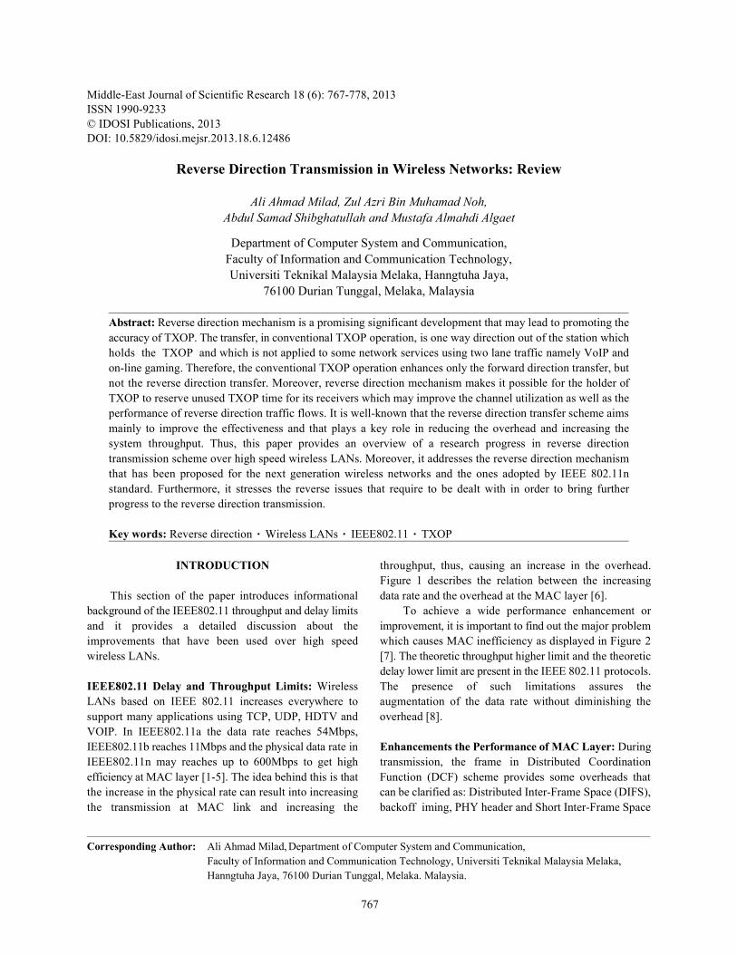
Fig. 8: Data service in RD protocol
packets flow in both directions was suggested. The The RD Protocol Exchange is Summarized as Follows:Initiator sends the RTS which contains NAV duration ofTXOP. According to the receipt of RTS, the responder The RD initiator (the TXOP holder) sends the PPDUchecks whether it has any packet to send to the initiator. which includes the RDG and that needs an immediateAnd when it has, it determines the duration required for response.the reverse direction data transfer. Under the normal The RD responder will respond with one or moreconditions, the CTS from responder must include the PPDUs. The first or only PPDU will include one orduration in the RTS minus, the sum of CTS and SIFS more ACKs or Block ACK frames (piggyback).duration. Regarding the reverse direction, the responder The last or only PPDU exchanged by the RDalso subtracts the value of reverse data duration from the responder in the burst will include any packets thatreceived duration in the RTS and sends the CTS with need a straight ACK or Block ACK response. Themodified duration to the initiator. The initiator checks the last PPDU will have the RDP/More PPDU subfield.duration in the CTS to insure the equality of the differenceexisting between the duration in the RTS and the CTS in Bidirectional Transmission:one hand and the CTS and SIFS duration. However, when Piggyback Scheme: When the data packets areit is not equal, then the initiator can realise that responder transferred in duplex directions from part A to part B andhas packet to exchange. Furthermore, as displayed in the data arrives at B, instead of sending a control frameFig. 8 below, the initiator can provide use to the responder from B to A, receiver B waits until the network layer at Bby the piggybacking data MPDU or BA Request (BAR) sends the next packet to A and the acknowledgment isMPDU, when this duration is less than the remaining attached in the data frame from B to A using the field ofTXOP. acknowledgment in the data frame header. Therefore, the
In [24], the authors identified the value of reverse acknowledgment gets a free ride in the data frame and thisdirection data flow characteristic of the emerging IEEE technique is known as piggybacking. One of the most802.11n WLAN standard and studied the benefit of using well-known advantages of piggyback scheme isit in terms of its performance and clarified the way this improving the efficiency, which plays the role in reducingmerit springs out. The authors also deduced that RDF the overhead and increasing the system throughput.diminishes the number of contentions by a factor of1.5 to 2 and thus decreases the number of collisions Overview of Piggyback: When the receiver station has awithin WLAN during EDCA phase. Besides, it diminishes frame to the sender station and allows sending the datathe MAC overhead associated with contention by frame with ACK to the sender, this process is called aitself. piggyback scheme. So the acknowledgment gets a free

Middle-East J. Sci. Res., 18 (6): 767-778, 2013
775
Fig. 9: The overhead with/without the piggyback scheme
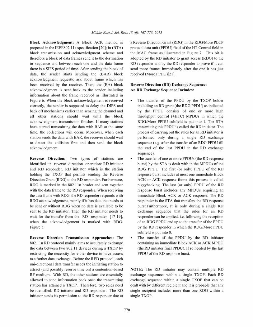
ride in the data frame and takes few bits and this is a In IEEE 802.11 WLAN data frame can increase thedistinct ACK. Therefore, each frame requires an ACK channel efficiency in a wireless. But the piggyback willheader and data frame (checksum). This means that the decrease the channel efficiency for frame transmissionpiggyback merely relies on the receiver since the fewer the delay. In Global control information the stations have aframes are sent, the fewer the frames that arrive and this is low transmission rate and in control frames. So thedependent the way the receiver is organized. However, piggyback deals with the problem concerning the lowthe emergence of the piggyback scheme has posed some physical transmission rate and evaluation of the effect ofcases of complexity. For example, the question of how this problem with respect to the average framelong the data link layer is supposed to wait until the transmission delay and the channel utilization. Therefore,packet is transmitted to piggyback the ACK is still a the purpose of proposing the delay-based piggybackposing a complex case. As far as we know, the link layer scheme by the authors was to mitigate the piggybackusually waits for a certain period of time and if this waiting problem [26]. And as revealed by the same authors, theperiod consumed by the data link layer is longer than the piggyback led to decreasing the channel efficiency whilesender timeout period, it is expected that the frame will be increasing the transmission delay for one station with lowretransmitted. Therefore, it is assumed that the data link physical transmission rate were present.layer must wait for fixed time like Ad hoc scheme such as [27] investigated the piggyback scheme when thenumber of milliseconds. On the other hand, one of the data frame was transmitted in two cases for the station. Ifbenefits of the piggyback is that the piggyback frame the frame was corrupted, so whole the process would re-does not need to rivalry the channel again in a case when start, or the data frame would be received successfully.the receiver has a frame to send to the sender. This is The researcher also showed that the wireless station turnbecause it does not need to be in the front of the queue on piggyback scheme when the packet is less thanbut the nearest frame to the destination at the sender. In 1100bytes. Moreover, the throughput is very low because[25] the researcher shows the overhead with/without the overhead is high and the data rate is better than thepiggyback mechanism in case when the frame belong to piggyback because the time missed in retransmitting thethe receiver is sent to the sender after receiving a frame as “data+Acknowlegment” frames is reduced. completion of the channel. After this a CTS frame time, an [28], the performance of the piggyback requests isRTS frame time, two SIFS times, a DIFS time and a random already evaluated, so the ratio of requests for theback off is required to be done by it. Otherwise, in a case piggyback and the influence on the delay werewhen the frame is possible to be piggybacked by the insistences for different traffic. With the large number ofreceiver to the sender along with the acknowledgment, the users, the performance increased by using the piggybackACK is sent by the sender as a way of acknowledging the requests and the web traffic model showed that largepiggybacked frame after reducing the SIFS time and the number of bandwidths can piggyback on previousoverhead has been already accomplishe (Figure 9). packets.
Middle-East J. Sci. Res., 18 (6): 767-778, 2013
776
[29] defined the piggyback problem that when the piggyback can be used to improve the bandwidthcontrol frame is piggybacked the channel efficiency is efficiency, but it is possible to increase the delay ofdecreased and at the same time, the station has a low channel access. The bandwidth efficiency with piggybackphysical rate. The researchers also showed that and requests can be saturated more quickly with the increasedevaluated the channel utilization with and without the number of SSs than that without piggyback requests.piggyback frame and they proved that utilization ofchannel means the ratio of the total frame transmission Related Study (Types of ACKs):time to the super frame length. So they solved the Cumulative Acknowledgment: This refers to the stance inpiggyback problem as the low physical rate by calculating which each acknowledgment confirms correct reception ofthe delay of the piggyback scheme and proposed the all bytes up to the ACK number. delay base piggyback scheme and found that thepiggyback was decreasing the channel efficiency while Acknowledgment Only Segment and Piggybacking:increasing the frame transmission delay even in one Based on this type of acknowledgments, the indication ofstation physical rate. However, when the physical the ACK is figured out through an ACK field in the TCPtransmission rate increases. In this method channel header. Therefore, in acknowledging that the bytes haveefficiency and the delay efficiency are also increased. been received correctly, the receiver can also create orTherefore, if the piggyback practices well, the channel develop an ACK segment which carries only the headerefficiency and the delay transmission will increase. that contains the ACK number. Another way of
But the proposed algorithm is expected to decrease acknowledging the correct received bytes is sending thethe average frame transmission delay and the channel ACK in data segment and when the ACK travels in thisutilization is estimated to be about 24% and 25%, data segment, the process is usually known asrespectively if there is one station which has low a piggybacking.physical transmission rate.
[30] Showed that the piggyback mechanism reduces Delayed Acknowledgment: This feature indicates that thethe delay for uplink and downlink packets and the packets TCP receiver has two different options: either it generatesloss probability for uplink traffic and downlink traffic for the ACK and receives a segment or it delays / postponesthe case of backoff method and piggyback method. For the ACK for a short period of time. In the case ofdownlink data, packets do not occur for piggyback following the second option which is delaying the ACK,method and the loss packets of downlink data packet for the receiver will be able to acknowledge two segments atthe backoff is not small. Moreover, the piggyback method one time and reduces the ACK traffic. However, in case ofreduces the energy consumption significantly and there a long time-delay of the ACK can cause a timeout andare no losses of downlink data packets. retransmission at the sender. Therefore, the recommended
[31] Investigated QoS data frames and their related span of time during which the receiver delays the ACKusage rules to increase the channel efficiency. A CF-boll should not be more than 500ms.used to grant the channel to QSTA and piggybacked inQoS the data frame to increase the channel efficiency. Duplicate ACK: This feature points at the case in whichHowever, the channel efficiency may be decreased by CF- the segment gets lost in traffic and the segment followingboll piggyback problem when QSTA associated in QBSS it arrives safely at the receiver. It is possible for theuses the low physical rate. The CF-boll piggyback scheme receiver to receive the data in a sequent series or numbervaries between 24 and 36Mbps depending on the traffic just beyond the range expected to be received. In such aload. case, the receiver performs the processes of buffering the
[32] Proposed a study in which the impacts of incoming bytes and re-generating the ACK for the byteschannel access, bandwidth and piggyback scheme on the which have been received so far in a sequence.performance were examined and it was observed that the Thus, re-generating the same ACK number can lead ACKbandwidth utilization can be improved if the bandwidth duplication phenomenon because the sender receivesfor random channel access is properly configured the same ACK several times. However, for the originalaccording to the channel access parameters, piggyback TCP, ACK duplication is normally ignored by the senderscheme and the traffic of network. The requests for [33].

Middle-East J. Sci. Res., 18 (6): 767-778, 2013
777
REFERENCES 12. Lee, T.H., Y.W. Kuo, Y.W. Huang and Y.H. Liu,
1. Abichar, Z. and J. Chang, 2013. Group-based medium acknowledgments? In: Vehicular Technologyaccess control for ieee 802.11 n wireless lans. Conference(VTC 2010-Spring), 2010 IEEE 71st. IEEE:
2. Akhmetov, D., 2006. 802.11 n: Performance results of pp: 1-5.reverse direction data flow. In: Personal, Indoor and 13. Li, T., Q. Ni, D. Malone, D. Leith, Y. Xiao andMobile Radio Communications, 2006 IEEE 17th T. Turletti, 2009. Aggregation with fragmentInternational Symposium on. IEEE: pp: 1-3. retransmission for very high-speed wlans.
3. Anwar, S., O. Mohamed, S. Shamala and A.H. Nor, IEEE/ACM Transactions on Networking (TON),Frame aggregation in wireless networks: Techniques 17(2): 591-604.and issues. IETE Technical Review, pp: 28. 14. Li, T., Q. Ni, T. Turletti and Y. Xiao, 2005. Performance
4. Committee, S., 2005. Wireless lan medium access analysis of the ieee 802.11 e block ack scheme in acontrol (mac) and physical layer (phy) specifications: noisy channel. In: Broadband Networks, 2005.Amendment 8: Medium access control (mac) quality BroadNets 2005. 2nd International Conference on.of service enhancements. IEEE Computer Society. IEEE: pp: 511-517.
5. Group, I.W., 2006. Ieee p802. 11n/d1. 0 draft 15. Lim, W.S. and Y.J. Suh, 2010. Achieving per-stationamendment to standard for information technology- fairness in ieee 802.11 wireless lans. In: World oftelecommunications and information exchange Wireless Mobile and Multimedia Networksbetween systems-local and metropolitan networks- (WoWMoM), 2010 IEEE International Symposium onspecific requirements-part 11: Wireless lan medium a. IEEE: pp: 1-9.access control (mac) and physical layer (phy) 16. Lin, Y. and V.W. Wong, 2006. Wsn01-1: Framespecifications: Enhancements for higher throughput. aggregation and optimal frame size adaptation for ieeeLocal and Metropolitan Networks, Specific 802.11 n wlans. In: Global TelecommunicationsRequirements, Part, pp: 11. Conference, 2006. GLOBECOM'06. IEEE. IEEE: pp:
6. Hassan, M. and R. Jain, 2004. High performance 1-6.tcp/ip networking. Pearson Prentice Hall. 17. Milad, A.A., Z.A.B.M. Noh, A.S. Shibghatullah, S.
7. He, J., K. Yang, K. Guild and H.H. Chen, 2008. Sahib, R. Ahmad and M.A. Algaet, 2013.On bandwidth request mechanism with piggyback Transmission control protocol performancein fixed ieee 802.16 networks. Wireless comparison using piggyback scheme in wlans.Communications, IEEE Transactions on, 7(12): Journal of Computer Science, 9(8): 967.5238-5243. 18. Mujtaba, S.A., 2005. Tgn sync proposal technical
8. Ketchum, J., S. Nanda, R. Walton, S. Howard, M. specification. IEEE 802.11-04/0889r7.Wallace, B. Bjerke, I. Medvedev, S. Abraham, A. 19. Ozdemir, M., D. Gu, A.B. McDonald and J. Zhang,Meylan and S. Surineni, 2005. System description and 2006. Enhancing mac performance with a reverseoperating principles for high throughput direction protocol for high-capacity wireless lans. In:enhancements to 802.11. QUALCOMM Inc. Vehicular Technology Conference, 2006. VTC-2006
9. Lee, H.J. and J.H. Kim, 2006. A optimal cf-poll Fall. 2006 IEEE 64th. IEEE: pp: 1-5.piggyback scheme in ieee 802.11 e hcca. In: 20. Park, J.S., T.O. Kim, K.J. Kim and B.D. Choi, 2009.Advanced Communication Technology, 2006. ICACT Performance analysis of ieee 802.15. 4 non-beacon2006. The 8th International Conference. IEEE: pp: 6. mode where downlink data packets are transmitted by
10. Lee, H.J., J.H. Kim and S.H. Cho, 2007. A delay-based piggyback method. In: Communications Workshops,piggyback scheme in ieee 802.11. In: Wireless 2009. ICC Workshops 2009. IEEE InternationalCommunications and Networking Conference, 2007. Conference on. IEEE: pp: 1-6.WCNC 2007. IEEE. IEEE: pp: 447-451. 21. Pries, R., D. Staehle and D. Marsico, 2007.
11. Lee, H.J., J.H. Kim and S. Cho, 2007. A novel Performance evaluation of piggyback requests in ieeepiggyback selection scheme in ieee 802.11 e hcca. In: 802.16. In: Vehicular Technology Conference, 2007. Communications, 2007. ICC'07. IEEE International VTC-2007 Fall. 2007 IEEE 66th. IEEE: pp: 1892-Conference on. IEEE: pp: 4529-4534. 1896.
2010. To piggyback or not to piggyback

Middle-East J. Sci. Res., 18 (6): 767-778, 2013
778
22. Rasheed, M.M., O. Ghazali and R. Budiarto, 2012. Fast 27. Wang, C.Y. and H.Y. Wei, 2009. Ieee 802.11 n macdetection of stealth and slow scanning worms in enhancement and performance evaluation. Mobiletransmission control protocol. Journal of Applied Networks and Applications, 14(6): 760-771.Sciences, 12: 2156-2163. 28. Xiao, Y., 2004. Packing mechanisms for the
23. Saeed, R.A. and S. Khatun, 2005. Design of microstrip ieee 802.11 n wireless lans. In: Globalantenna for wlan. Journal of Applied Sciences, 5(1): Telecommunications Conference, 2004.47-51. GLOBECOM'04. IEEE. IEEE: pp: 3275-3279.
24. Saif, A., M. Othman, S. Subramaniam and 29. Xiao, Y., 2005. Ieee 802.11 n: Enhancements for higherN.A.W.A. Hamid, 2012. An enhanced a-msdu frame throughput in wireless lans. Wirelessaggregation scheme for 802.11 n wireless networks. Communications, IEEE, 12(6): 82-91.Wireless Personal Communications, 66(4): 683-706. 30. Xiao, Y., 2005. Ieee 802.11 performance enhancement
25. Singh, M. and B. Edwards, 2004. System description via concatenation and piggyback mechanisms.and operating principles for high throughput Wireless Communications, IEEE Transactions on,enhancementsto 802.11. IEEE 802.11-04-0886-00-000n, 4(5): 2182-2192.Aug. 31. Xiao, Y. and J. Rosdahl, 2002. Throughput and delay
26. Skordoulis, D., Q. Ni, H.H. Chen, A.P. Stephens, limits of ieee 802.11. Communications Letters, IEEE,C. Liu and A. Jamalipour, 2008. Ieee 802.11 n mac 6(8): 355-357.frame aggregation mechanisms for next-generation 32. Xiao, Y. and J. Rosdahl, 2003. Performance analysishigh-throughput wlans. Wireless Communications, and enhancement for the current and future ieeeIEEE, 15(1): 40-47. 802.11 mac protocols. ACM SIGMOBILE Mobile
Computing and Communications Review, 7(2): 6-19.