Revealing austenite grain boundaries by thermal etching:...
23
Revealing austenite grain boundaries by thermal etching: advantages and disadvantages C. García de Andrés, F. G. Caballero, C. Capdevila, and D. San Martín Departamento de Metalurgia Física, Centro Nacional de Investigaciones Metalúrgicas (CENIM), Consejo Superior de Investigaciones Científicas (CSIC), Avda. Gregorio del Amo, 8, 28040 Madrid, Spain Abbreviated Title: Thermal etching method Abstract This paper reviews the method of thermal etching for revealing the prior austenite grain boundary in steels. This method involves preferential transfer of material away from grain boundaries, when the steel is exposed to a high temperature in an inert atmosphere. Thus, during austenitisation of a pre-polished sample, grooves are formed at the intersections of the austenite grain boundary with the polished surface. These grooves remain intact after cooling and are clearly visible at room temperature outlining the austenite grain boundaries. However, at very high austenitisation temperatures, those grooves might interfere with the own advance of the austenite grain boundary on the surface. In that case, this technique could lead to a wrong measurement of the austenite grain boundary. The aim of this work is to study the advantages and disadvantages of the technique to reveal the austenite grain boundary in microalloyed steels.
Transcript of Revealing austenite grain boundaries by thermal etching:...
Revealing austenite grain boundaries by thermal etching: advantages and
disadvantages
C. García de Andrés, F. G. Caballero, C. Capdevila, and D. San Martín
Departamento de Metalurgia Física, Centro Nacional de Investigaciones Metalúrgicas
(CENIM), Consejo Superior de Investigaciones Científicas (CSIC), Avda. Gregorio del Amo,
8, 28040 Madrid, Spain
Abbreviated Title: Thermal etching method
Abstract
This paper reviews the method of thermal etching for revealing the prior austenite grain
boundary in steels. This method involves preferential transfer of material away from grain
boundaries, when the steel is exposed to a high temperature in an inert atmosphere. Thus,
during austenitisation of a pre-polished sample, grooves are formed at the intersections of the
austenite grain boundary with the polished surface. These grooves remain intact after cooling
and are clearly visible at room temperature outlining the austenite grain boundaries. However,
at very high austenitisation temperatures, those grooves might interfere with the own advance
of the austenite grain boundary on the surface. In that case, this technique could lead to a
wrong measurement of the austenite grain boundary. The aim of this work is to study the
advantages and disadvantages of the technique to reveal the austenite grain boundary in
microalloyed steels.
1. Introduction
The validity and the efficiency of techniques to reveal austenite grain boundaries in steels are
uncertain, because they depend on the chemical composition, heat treatment, and other not
well-identified factors. Therefore, the revealing of austenite grain boundaries could be a
difficult task, especially in medium-carbon microalloyed steels, which showed low sensibility
to chemical etching [1,2]. Recent works in medium-carbon microalloyed steels [3,4]
demonstrated that procedures based on the combination of heat treatment and chemical
etching are unable to reveal the austenite grain boundaries for certain austenitisation
conditions in a given steel and for a particular condition in steels with similar chemical
compositions without an apparent reason. However, the thermal etching method gave
excellent results in all the tested steels at every austenitisation condition, even at those in
which no other method was effective for revealing the austenite grain boundaries. The thermal
etching was the most adequate method for revealing the prior austenite grain boundary of this
kind of steels.
The method of thermal etching consists in revealing the austenite grain boundaries in a pre-
polished sample by the formation of grooves in the intersections of austenite grain boundaries
with the polished surface, when the steel is exposed to a high temperature in an inert
atmosphere. These grooves decorate the austenite grain boundary and make it visible at room
temperature in the optical microscope. Thermal etching results in equilibration of the triple
junction between the grain boundary and the free surface [5]. This equilibrium is set up
almost instantaneously at high temperatures and so the free surface, adjacent to the line where
the grain boundary emerges, becomes tightly curved as Fig. 1 shows. Mullins [6-7] developed
a theory of grain boundary grooving in terms of the mechanisms of surface diffusion, volume
diffusion, and evaporation-condensation.
Thermal grooves can develop in association with mobile as well as stationary grain
boundaries. Whether such grooves affect the mobility of the boundaries has, however, been
the subject of some debate [7-10]. Mullins [7] showed that moving grooves have a different
profile to their stationary counterparts, compare Figs. 1 and 2. The latter shape refers to a
steady-state groove migrating at a constant speed. Mullins went on to apply his model to
explain the presence of families of multiple grain boundary traces observed on the surface of
annealed pure copper sheet. He attributed that observation to spasmodic movement of the
boundaries at the free surface, the visible traces being formed by surface grooving at periods
when the boundaries were stationary, i.e. θ < θc. Rapid non-grooving motion started when θ
became sufficiently greater than θc, thus allowing the surface boundaries to catch up with
their continuously mobile, subsurface links.
In a more recent assessment of thermal grooving at migrating grain boundaries, Allen [8]
suggested that the spasmodic boundary movements considered by Mullins were a special
case, applying to groove mobility only at extremely slow grain growth rates. Allen argued
that, under more general conditions, the grooves grow only to the proportion of their steady-
state size which will allow them to maintain a velocity synchronised with that of the
underlying grain boundaries. Support for Allen mechanism can be gained from the work of
Halliday [9].
More recently, Rabkin et al. [10-11] have shown by atomic force microscopy technique that
the surface morphology in the region of grain boundary grooves is much more complex than
is implied by the classical profile analysed more than 40 years ago by Mullins. Fig. 3.a and
Fig. 3.b show light and atomic force microscopy images, respectively, of a grain boundary

migrated during annealing. Moreover, Fig. 3.c represents the linear profile containing original
(OGB) and final (FGB) positions of the moving grain boundary. From Fig. 3.b and Fig. 3.c, It
can be seen that the region swept by the migrating grain boundary exhibits a level
intermediate between those of the left and right grains. The root of the grain boundary groove
at the original position is blunted, indicating that the grain boundary left the original position
in the middle of the annealing process, allowing sufficient time for smoothing of the sharp
groove root by diffusion.
It is widely accepted that the surface grooves that are formed during treatments where the
grain boundaries are stationary are an exact copy of the grain structure existing in the bulk of
the sample. However, there has been dispute in the literature on the pinning effects of surface
grooves during thermal treatments where grain boundaries in the bulk of the material are
mobile. Any convincing argument forwarding that pinning of boundaries by thermal grooves
occurs during austenitisation, it would make questionable any grain measurements based upon
these surface structures. In this sense, a review of the method of thermal etching for revealing
the prior austenite grain boundary in steels is important. The aim of this work is to study the
advantages and disadvantages of the thermal etching technique to reveal the austenite grain
boundaries in microalloyed steels, evaluating possible measurement errors caused by
boundary sliding phenomena.
2. Experimental Procedure
Three medium-carbon microalloyed steels with different vanadium and titanium content have
been studied. Their chemical composition is listed in Table 1.
Cylindrical samples of 5 mm in diameter and 12 mm in length were used to reveal grain
boundaries by the thermal etching method. For that purpose, a 2 mm wide surface was
generated along the longitudinal axis of samples by polishing and finishing with 1 µm
diamond paste. Later on, those samples were heat-treated in a radiation furnace at a heating
rate of 5 Ks-1 to the austenitisation conditions listed in Table 2. A vacuum pressure higher
than 1 Pa is advised to avoid oxidation on the polished surface. Subsequently, samples were
cooled down to room temperature at a cooling rate of 1 Ks-1. Likewise, some samples were
gas quenched from austenitisation temperatures to investigate the role of the cooling rate in
this technique. It is important to mention that samples tested after thermal etching do not
require metallographic preparation after heat treatment.
On the other hand, to examine whether the surface grooves formed during treatment resemble
the grain boundaries in the bulk of the material and therefore, the grain size in the bulk and on
the surface of the sample are the same, the prior-austenite grain boundary was revealed by
more traditional methods [3,4]. As mentioned before, and without any rigorous explanation
found yet, traditional procedures did not work with all the steels in the same way, neither with
all the austenitisation conditions tested in the same steel.
In V steel, the prior-austenite grain boundary in the bulk of the sample was determined on
cylindrical samples 2 mm in diameter and 12 mm in length, heated at a rate of 5 Ks-1 to the
austenitisation conditions indicated in Table 2. After austenitisation, they were gas quenched
to room temperature. The chemical etching which gave positive results in this steel revealing
the prior-austenite grain boundary at all austenitisation temperatures was a solution formed by
100 ml of distilled water, 2 g of picric acid (C6H3N3O7), 50 ml of sodium alkylsulfonate
(‘Teepol’) and some drops of HCl.
In TiV steel, the above mentioned etchant only gave acceptable results for the two lowest
austenitisation temperatures (950ºC and 1000ºC) as repeated polishing and etching cycles

were practised. For the austenitisation conditions of the TiV steel, in which it was impossible
to reveal the prior-austenite grain boundary by the chemical procedure, an indirect method
was tested to visualise the prior-austenite grain at room temperature. For that procedure,
cylindrical samples 2mm in diameter and 12mm in length were used. They were heated at a
constant rate of 5 Ks-1 to the austenitisation conditions listed in Table 2. Subsequently,
samples were isothermally transformed at a intermediate temperature during a certain time.
Finally, samples were quenched to room temperature. The temperature and time of isothermal
transformation are, respectively, the temperature and time required to outline the prior-
austenite grain boundaries by the formation of allotriomorphic ferrite [3,4]. This
microstructure can be easily revealed by chemical etching with a 2% Nital solution.
Finally, to reveal the prior-austenite grain boundary in the bulk of the Ti steel sample, cubic
samples with 5 mm in edge length were heat-treated in a non-protected (free) atmosphere in
an electric furnace preheated at the austenitisation temperatures Tγ from Table 2. After a
holding time tγ (Table 2), the samples were quenched in water and afterwards tempered at
550ºC during 5 hours. The combination of this treatment and the repeated cycles of etching
and polishing with the reagent formed by 100 ml of distilled water, 2 g of picric acid
(C6H3N3Ot), 50 ml of Teepol and some drops of HCl, allowed to reveal the prior-austenite
grain boundary at low (950, 1000, 1050ºC) and high temperatures (1200, 1225, 1250ºC) in
this steel. At the austenitisation temperatures of 1100 and 1150 ºC the prior-austenite grain
boundary could be only revealed by thermal etching.
The prior austenite grain size (PAGS) was directly measured on optical micrographs using a
linear intercept procedure [12,13]. The austenite grain size was represented by the mean grain
diameter which was estimated by counting the number of grains intercepted by straight lines
long enough to yield at least 50 intercepts in total.
3. Results and Discussion
Figure 4 shows some micrographs of the prior austenite grain revealed by thermal etching in
V, Ti, and TiV steels. This method gave excellent results at all the austenitisation
temperatures tested and for the three steels, even in Ti steel for intermediate temperatures
(1100ºC and 1150ºC), at which none of the other methods were successful. This method is
rapid and practicable since no metallographic preparation is required after heat treatment.
Moreover, it is worthy pointing out that, contrary to conventional methods, a fully martensite
microstructure is not necessary to reveal the prior austenite grain boundaries. This
undoubtedly facilitates the revealing of the austenite grain boundaries in those steels in which,
because of insufficient hardenability, a martensitic microstructure cannot be obtained by
quenching. Effectively, a cooling rate of 1 Ks-1 has been used in the method of thermal
etching, obtaining a microstructure of ferrite and pearlite in the three steels investigated.
As mentioned above, at very high austenitisation temperatures where superficial diffusion and
evaporation processes are important, grooves can interfere with the austenite grain boundary
advance on the surface [7]. When this occurs, traces of old grooves or ghost traces can be
observed on the surface, showing the advance of the grain boundary while austenite grains are
still growing. An example of this phenomenon is shown in Fig. 5, where the austenite grain is
revealed with some ghost traces in V steel at 1250ºC and 180 s of austenitisation for a 1 Ks-1
cooling rate. Mullins [7] was the first to associate the presence of ghost traces with a
spasmodic sliding phenomenon of the grain boundaries along the polished surface. When this
occurs, differences between the inner and outer grain size on the sample surface can be found,
which could lead to false measurements of the PAGS.
Among the three steels investigated, ghost traces were observed most clearly in V steel, for
two austenitisation conditions: at 1250ºC and 180 s (Fig. 5) and at 1200ºC and 300 s (Fig 6.a).
However, ghost traces were absent in the microstructure formed during austenitisation at 1200
ºC and 180 s (Fig. 6.b). The comparison of Fig. 5 (V steel, 1250ºC and 180 s) and Fig. 6.b (V
steel, 1200 ºC and 180 s), suggests that as the austenitisation temperature increases, the
presence of ghost traces in the microstructure is more noticeable. Moreover, from the
comparison of Fig 6.a (V steel, 1200 ºC and 300 s) and Fig. 6.b (V steel, 1200 ºC and 180 s),
it can be concluded that for the same austenitisation temperature, ghost traces are revealed
more clearly for higher austenitisation times. Both facts are related to the austenite grain
mobility, which decreases when the grain size increases. The lower the mobility of the
austenite grain, the greater the interference of the grooves with the grain boundary movement
on the surface. Likewise, at higher temperature, the superficial diffusion and evaporation
processes are more important leading to deeper grooves which hinder the advance of the grain
boundary.
Moreover, it has been experimentally verified, in the V steel, that ghost traces on the sample
surface can be avoided by quenching instead of cooling slowly. Micrographs in Fig 6.a and
Fig 6.c correspond to the same steel and the same austenitisation conditions (1200ºC and 300
s), but the former sample was cooled at 1 Ks-1, while the latter was quenched. Whereas
micrograph in Fig 6.a clearly reveals ghost traces, making difficult the grain size
measurement, micrograph in Fig 6.c is free of old grooves and the grain size measurements
are much easier. It can be suggested from this result that the strain associated with the
martensitic transformation is able to remove the ghost traces observed in Fig. 6.a. On the

other hand, at slow cooling, the austenite grain can continue its growth during cooling at high
temperatures, which complicates an accurate determination of the austenite grain size.
Therefore, at higher austenitisation temperature (> 1200 ºC in the V steel), quenching of the
sample is recommended to reveal the prior austenite grain boundary by the thermal etching
method.
In Ti steel (Fig. 7.a) no ghost traces are observed at any austenitisation temperature with
holding times of 180 s, whereas some traces at temperatures higher than 1200ºC and times of
60 s can be distinguished in TiV steel (Fig. 7.b), but not as clearly as in V steel.
Finally, Fig. 8 shows the temperature evolution of the PAGS on the polished surface of the
sample revealed by the thermal etching method, compared with that in the bulk of the sample
revealed by a conventional method. The PAGS on the polished surface and in the bulk of the
sample are similar, even at the highest austenitisation temperatures in the V steel. It can be
therefore concluded that the measurement of the PAGS is not significantly affected by the
spasmodic advance of the grain boundary associated with the presence of ghost traces in the
thermal etching procedure.
4. Conclusions
The method of thermal etching for revealing the prior austenite grain boundary gives
excellent results in microalloyed steels for all the austenitisation temperatures, even for
temperatures where other methods cannot clearly reveal the austenite grain. This method is

quick and practical because no metallographic preparation is required after the heat treatment
and it is not necessary to have a martensitic final microstructure, as in conventional methods.
However, at very high austenitisation temperatures, the grooves which reveal the austenite
grain boundary can interfere with the advance of the austenite grain boundary, producing the
spasmodic migration of the grain boundaries along the polished surface and the presence of
ghost traces in the boundaries. Nevertheless, measurement of the PAGS on the surface has
proven to be similar to the PAGS in the bulk of the sample, and the difficulties of PAGS
measurement caused by the presence of these traces can be avoided quenching the sample
after the austenitisation. There is not dough that thermal etching is the most adequate method
for revealing the PAGS of microalloyed steels.
Acknowledgements
The authors acknowledge financial support from Ministerio de Ciencia y Tecnología (MCYT)
(Proyect PETRI 95-0436-OP). F. G. Caballero would like to thank the Dirección General de
Investigación de la Comunidad Autónoma de Madrid (CAM) for the financial support in the
form of a Postdoctoral Research Grant. C. Capdevila would like to express his gratitude to the
Consejo Superior de Investigaciones Científicas for financial support as a Post-Doctoral
contract (I3P PC-2001-1).
References
[1] L. Zhang and D.C. Guo, A general etchant for revealing prior-austenite grain
boundaries in Steels, Mater. Chart. 30:299-305 (1993).
[2] P. Baldinger, G. Posch and A. Kneisslaas, Revealing austenitic grains in microalloyed
steels by picric acid etching, Pract. Metallogr. 31:252-261 (1994).
[3] C. García de Andrés, M.J. Bartolomé, C. Capdevila, D. San Martín, F.G. Caballero and
V. López, Metallographic techniques for the determination of the austenite grain size in
medium carbon microalloyed steels, Mater. Chart. 46/5:389-398 (2001).
[4] C. García de Andrés, M.J. Bartolomé, C. Capdevila, D. San Martín, F.G. Caballero, V.
López and J. Vara, Técnicas para revelar el borde de grano austenítico en aceros
microaleados, Revista Metalurgia de Madrid 37:528-539 (2001).
[5] E. Rabkin and L. Klinger, The fascination of grain boundary grooves, Materials Science
and Technology 17:772-776 (2001).
[6] W.W. Mullins, Theory of thermal grooving, J. Appl. Phys. 28:333-339 (1957).
[7] W.W. Mullins, The effect of thermal grooving on grain boundary motion, Acta Metall.
6:414-427 (1958).
[8] D.J. Allen, Thermal grooving at migrating grain boundaries, Scripta Met. 16:5-9 (1982).
[9] W.I. Halliday, Determination of the austenitic grain size of steel using a thermal etching
method, in ISI Special Report No. 81, Iron and Steel Inst., London, pp. 65-67 (1963).
[10] E. Rabkin, L. Klinger, T. Izyumova, A. Berner and V. SEmenov, Grain boundary
grooving with simultaneous grain boundary sliding in Ni-rich NiAl, Acta Mater.
49:1429-1438 (2001).
[11] E. Rabkin, L. Klinger and V. SEmenov, Grain boundary grooving at the singular
surfaces, Acta Mater. 48:1533-1540 (2000).

[12] E.E. Underwood, Quantitative Stereology, Addison-Wesley Reading, MA. (1970)
[13] G.F. Vander Voort, Metallography: Principles and Practice, McGraw-Hill Book
Company, N.Y. pp. 440-465 (1984).
Fig. 1. Groove formed at the intersection of a free surface with a grain boundary.
Fig. 2. Characteristic steady-state profile of a thermal groove formed at a free-surface by a
moving grain boundary. θc is the critical grain boundary angle.
Fig. 3. (a) Light microscopy, (b) atomic force microscopy images of migrating grain
boundary, and (c) and its linear profile containing original (OGB) and final (FGB) grain
boundary positions [10].
Fig. 4. Optical micrographs of the prior austenite grains at different austenitisation conditions
revealed by thermal etching in V steel: a) 950 ºC and 180 s; b) 1050 ºC and 180 s; c)
1150 ºC and 180 s; in Ti steel: d) 950 ºC and 180 s; e) 1050 ºC and 180 s; f) 1150 ºC
and 180 s; in TiV steel: g) 950 ºC and 60 s; h) 1050 ºC and 60 s; i) 1150 ºC and 60 s. All
the samples were cooled from austenitisation temperature at a rate of 1 Ks-1.
Fig. 5. Old grooves or ghost traces observed on the austenite grains revealed by thermal
etching at 1250 ºC and 180 s in V steel. The sample was cooled from austenitisation
temperature at a rate of 1 Ks-1.
Fig. 6. Optical micrographs of the prior austenite grains at different austenitisation conditions
revealed by thermal etching in V steel: a) 1200 ºC and 300 s; b) 1200 ºC and 180 s.
Both samples were cooled from austenitisation temperature at a rate of 1 Ks-1 c) 1200
ºC and 300 s, this sample was gas quenched from austenitisation temperature.
Fig. 7. Optical micrographs of the prior austenite grains revealed by thermal etching at a)
1250 ºC and 180 s in Ti steel and b) 1250 ºC and 60 s in TiV steel. Both samples were
cooled from austenitisation temperature at a rate of 1 Ks-1.
Fig. 8. Temperature evolution of the prior austenite grain size (PAGS) on the polished surface
of the sample revealed by the thermal etching method, compared with that in the bulk of
the sample revealed by a conventional method: a) V steel, austenitisation time: 180 s; b)
Ti steel, austenitisation time: 180 s; c) TiV steel, austenitisation time: 60 s.
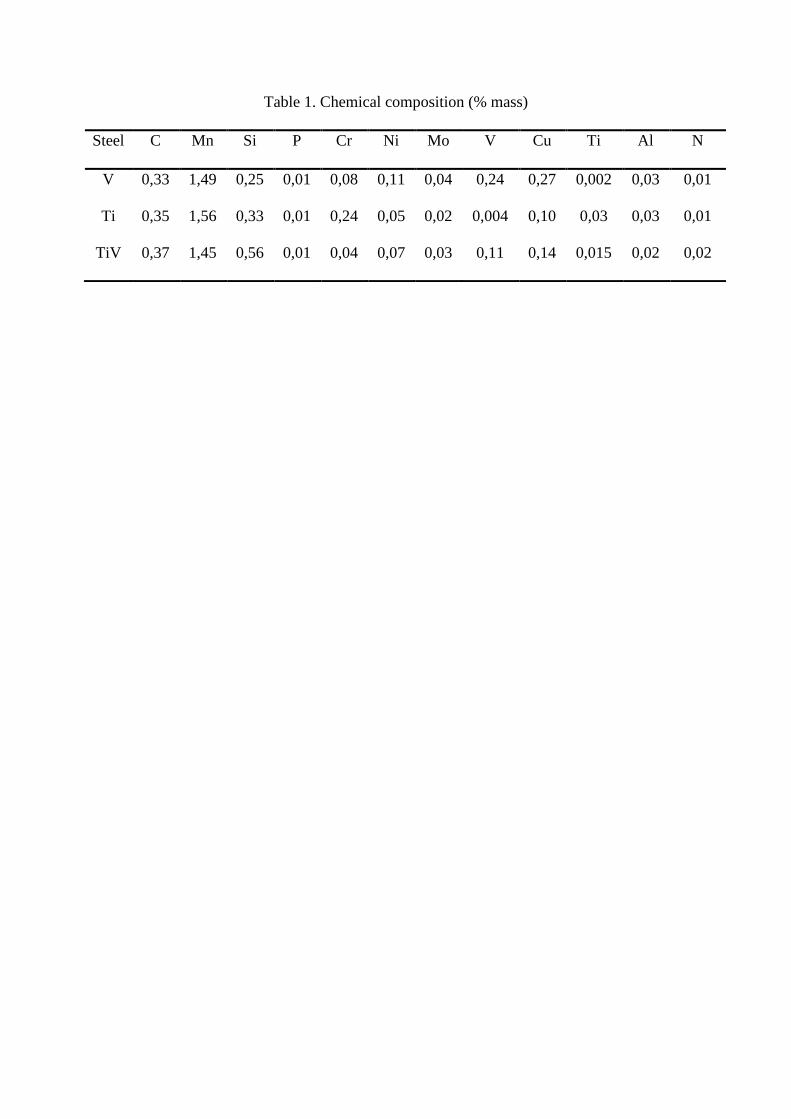
Table 1. Chemical composition (% mass)
Steel C Mn Si P Cr Ni Mo V Cu Ti Al N
V 0,33 1,49 0,25 0,01 0,08 0,11 0,04 0,24 0,27 0,002 0,03 0,01
Ti 0,35 1,56 0,33 0,01 0,24 0,05 0,02 0,004 0,10 0,03 0,03 0,01
TiV 0,37 1,45 0,56 0,01 0,04 0,07 0,03 0,11 0,14 0,015 0,02 0,02

Table 2. Austenitisation conditions
Steel Tγ (ºC) tγ (s)
V 950, 1000, 1050, 1100, 1150, 1200, 1250 180, 300
Ti 950, 1000, 1050, 1100, 1150, 1200, 1225, 1250 180
TiV 950, 1000, 1050, 1100, 1150, 1200, 1250 60
Tγ is austenitisation temperature
tγ is austenitisation time
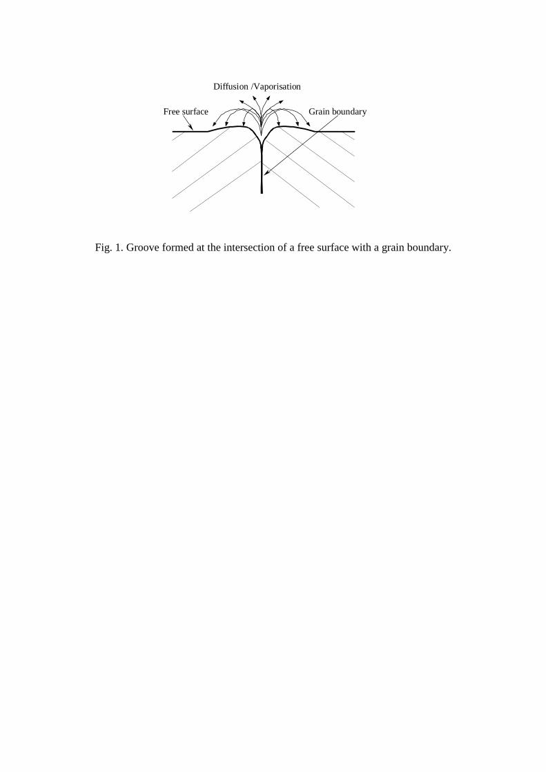
Fig. 1. Groove formed at the intersection of a free surface with a grain boundary.
Free surface Grain boundary
Diffusion /Vaporisation
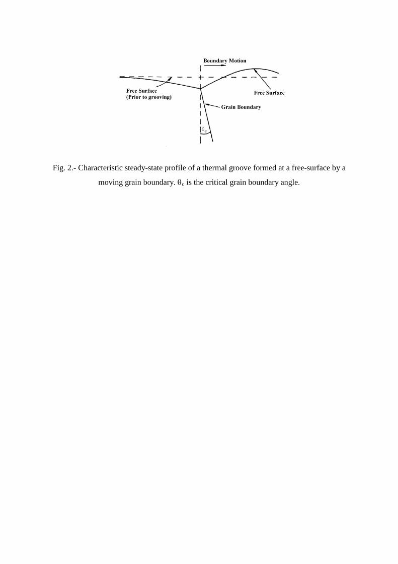
Fig. 2.- Characteristic steady-state profile of a thermal groove formed at a free-surface by a
moving grain boundary. θc is the critical grain boundary angle.
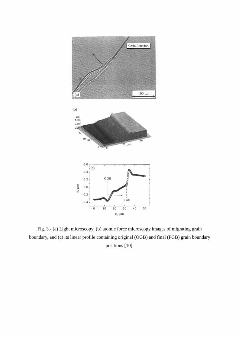
Fig. 3.- (a) Light microscopy, (b) atomic force microscopy images of migrating grain
boundary, and (c) its linear profile containing original (OGB) and final (FGB) grain boundary
positions [10].
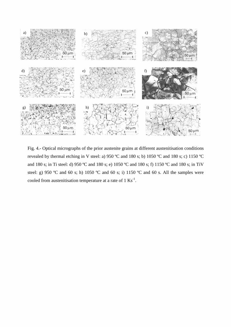
Fig. 4.- Optical micrographs of the prior austenite grains at different austenitisation conditions
revealed by thermal etching in V steel: a) 950 ºC and 180 s; b) 1050 ºC and 180 s; c) 1150 ºC
and 180 s; in Ti steel: d) 950 ºC and 180 s; e) 1050 ºC and 180 s; f) 1150 ºC and 180 s; in TiV
steel: g) 950 ºC and 60 s; h) 1050 ºC and 60 s; i) 1150 ºC and 60 s. All the samples were
cooled from austenitisation temperature at a rate of 1 Ks-1.
a) b) c)
d) e) f)
g) h) i)

Fig. 5.- Old grooves or ghost traces observed on the austenite grains revealed by thermal
etching at 1250 ºC and 180 s in V steel. The sample was cooled from austenitisation
temperature at a rate of 1 Ks-1.
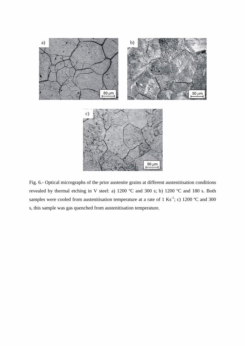
Fig. 6.- Optical micrographs of the prior austenite grains at different austenitisation conditions
revealed by thermal etching in V steel: a) 1200 ºC and 300 s; b) 1200 ºC and 180 s. Both
samples were cooled from austenitisation temperature at a rate of 1 Ks-1; c) 1200 ºC and 300
s, this sample was gas quenched from austenitisation temperature.
b) a)
c)
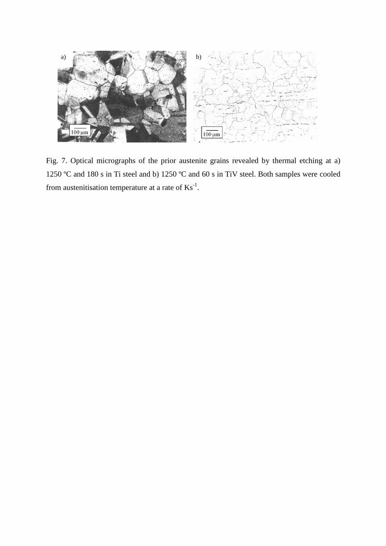
Fig. 7. Optical micrographs of the prior austenite grains revealed by thermal etching at a)
1250 ºC and 180 s in Ti steel and b) 1250 ºC and 60 s in TiV steel. Both samples were cooled
from austenitisation temperature at a rate of Ks-1.
a) b)

Fig. 8.- Temperature evolution of the prior austenite grain size (PAGS) on the polished
surface of the sample revealed by the thermal etching method, compared with that in the bulk
of the sample revealed by a conventional method: a) V steel, austenitisation time: 180 s; b) Ti
steel, austenitisation time: 180 s; c) TiV steel, austenitisation time: 60 s.
0
40
80
120
160
200
900 1000 1100 1200 1300Temperature (ºC)
PAG
S ( µ
m)
Thermal etching
Other method
V Steel
0
40
80
120
900 1000 1100 1200 1300Temperature (ºC)
PAG
S ( µ
m)
Thermal etching
Other method
Ti Steel
0
40
80
120
900 1000 1100 1200 1300Temperature (ºC)
PAG
S ( µ
m)
Thermal etching
Other method
TiV Steel