Return Activated Sludge Pumping System: From … 19, 2013 Return Activated Sludge Pumping System:...
35
June 19, 2013 Return Activated Sludge Pumping System: From Conceptual Design To Daily Operation City of Columbus The Division of Sewerage and Drainage Gary Hickman – Columbus DOSD Mike Rudisell – Burgess & Niple
-
Upload
truongkien -
Category
Documents
-
view
216 -
download
2
Transcript of Return Activated Sludge Pumping System: From … 19, 2013 Return Activated Sludge Pumping System:...

June 19, 2013
Return Activated Sludge Pumping System: From Conceptual Design To Daily Operation
City of Columbus The Division of Sewerage and Drainage
Gary Hickman – Columbus DOSD Mike Rudisell – Burgess & Niple
Project ‘Driver’ Jackson Pike Wastewater Treatment Plant
Two (2) Consent Orders (2002 & 2004) Signed with Ohio EPA to eliminate SSOs and reduce CSOs Development of Wet Weather Management Plan as a response
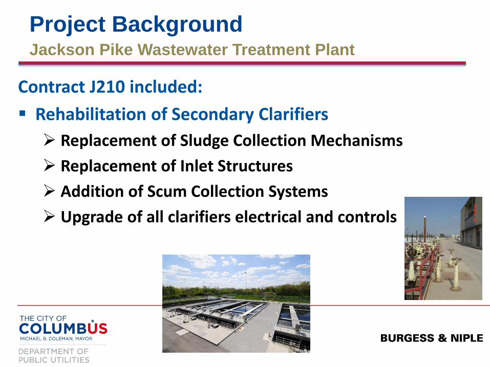
Project Background Jackson Pike Wastewater Treatment Plant
Contract J210 included:
Rehabilitation of Secondary Clarifiers
Replacement of Sludge Collection Mechanisms
Replacement of Inlet Structures
Addition of Scum Collection Systems
Upgrade of all clarifiers electrical and controls

Project Background Jackson Pike Wastewater Treatment Plant
Contract J210 included:
Modifications to Pumping Systems
Upgrade of Influent Pumps’ electrical/controls
Increase capacity of flushing water system

Project Background Jackson Pike Wastewater Treatment Plant
Contract J210 included: Wet Weather Management Improvements
Increase RAS pumping capacity
Addition of step feed aeration capabilities
Replacement of aeration diffuser systems
Elimination of various plant hydraulic restrictions
Addition of flocculation baffles in secondary clarifiers

Peak Hourly Design Flow: 165 MGD
Total Average Daily Design Flow: 68.0 MGD
A-Plant ADDF: 45.3 MGD
B-Plant ADDF: 22.7 MGD
Design RAS Rates: 30% Min. & 75% Max.
A-Plant RAS Range: 14-34 MGD
B-Plant RAS Range: 7-17 MGD
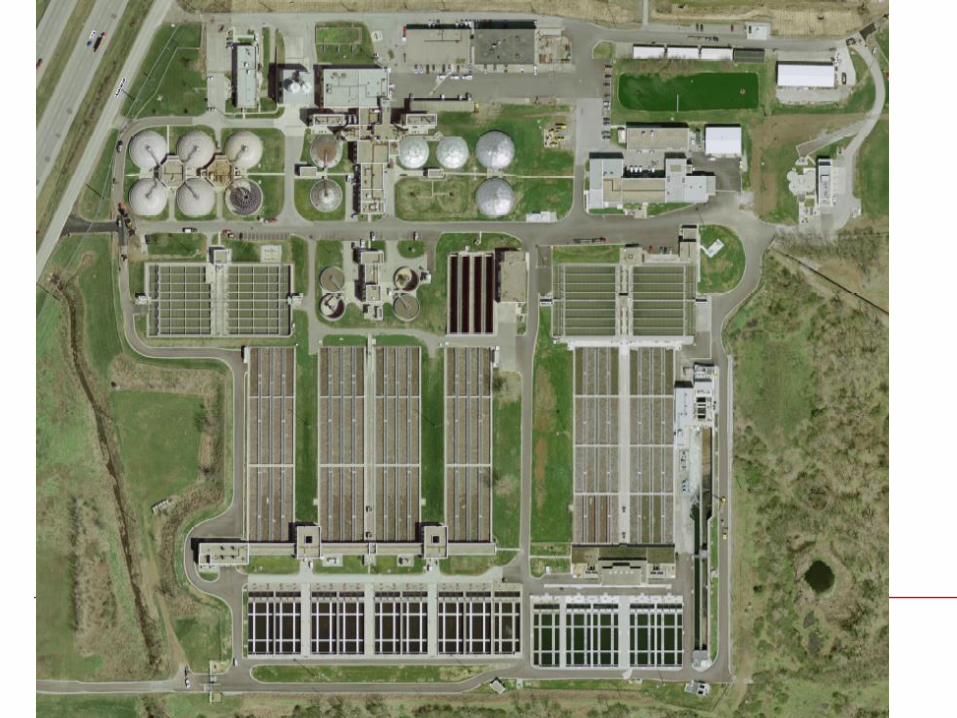
Facility Background Jackson Pike Wastewater Treatment Plant

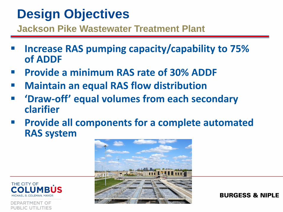
Design Objectives Jackson Pike Wastewater Treatment Plant
Increase RAS pumping capacity/capability to 75% of ADDF Provide a minimum RAS rate of 30% ADDF Maintain an equal RAS flow distribution ‘Draw-off’ equal volumes from each secondary clarifier Provide all components for a complete automated RAS system

Design Challenges Jackson Pike Wastewater Treatment Plant
“Skewed Geometry”
Four (4) Aeration Tanks (A-09 to A-12) Two (2) RAS Pumping Wells (B-Plant East & West) Five (5) Secondary Clarifiers (S-10 to S14)

Project Challenges Jackson Pike Wastewater Treatment Plant
West RAS Well
3 Clarifiers
10.2 MGD Firm
East RAS Well
2 Clarifiers
6.8 MGD Firm

The Design Process Jackson Pike Wastewater Treatment Plant
Evaluate clarifier ‘underflow’ to RAS Wells
Consider Valve Modulation vs. Most-Open-Valve concepts for ‘underflow’
Evaluate flow metering options
RAS Pumps’ Discharge to Aeration Tanks
Clarifier Underflow Piping to RAS Wells
Consider AFDs for each pumping unit
Develop an effective control strategy

The Design Process Jackson Pike Wastewater Treatment Plant
Select appropriate pumps that can meet RAS return rates (30 to 75% of ADDF)
Determine range of flows for the various pump operating combinations by varying speeds
Evaluate RAS underflow hydraulics to ensure equal ‘draw-off’ can be achieved
Evaluate all existing piping and valves suitable for increased flow rates – upsize as necessary

The Design Process Jackson Pike Wastewater Treatment Plant
Pump Design
Size pump for max condition: two pumps operating at full speed, i.e. 10.2 MGD/2 = 5.1 MGD = 3,550 gpm (60 Hz)
Determine system pumping head (TDH) at this condition
Select pump/impeller based on this design point
Determine minimum speed turndown for pumps
Check one pump operation for NPSH and reduced speeds
Evaluate the effect of a clarifier out of service

The Design Process Jackson Pike Wastewater Treatment Plant
Utilized a Pump Hydraulics Program with AFD analysis (Fathom by Applied Flow Technologies)

The Design Process Jackson Pike Wastewater Treatment Plant

The Design Solution Jackson Pike Wastewater Treatment Plant
Pump Selection
Three (3) horizontal centrifugal, solids handling pumps for each RAS Well - identical in size
Two (2) pumps operating at full speed achieve maximum RAS return rate; one standby
Capability to run all three (3) pumps if desired
Turndown limit established for the pumps = 37 Hz (62%)

The Design Solution Jackson Pike Wastewater Treatment Plant
Design Features For Automated RAS Control
Modulating valves and flow meters on each underflow pipe from the secondary clarifiers
AFD for each RAS pump to vary speed and expand range of RAS return rate
Flow meters on pump discharge from each RAS Well
Level instrumentation provided for each RAS Well
All required electrical panels and inputs/outputs for complete automated control of clarifier draw-off and return pumping
The Design Solution Jackson Pike Wastewater Treatment Plant
Manual and Automatic Control Modes
Design provided components for complete automated control and flexibility
Control narratives, algorithms, programming, and screen shots developed with DOSD input
“Automatic” = Prompt User to manually change settings (start/stop RAS pumps)
Programming could be modified in future to revise operating strategies
The Design Solution Jackson Pike Wastewater Treatment Plant
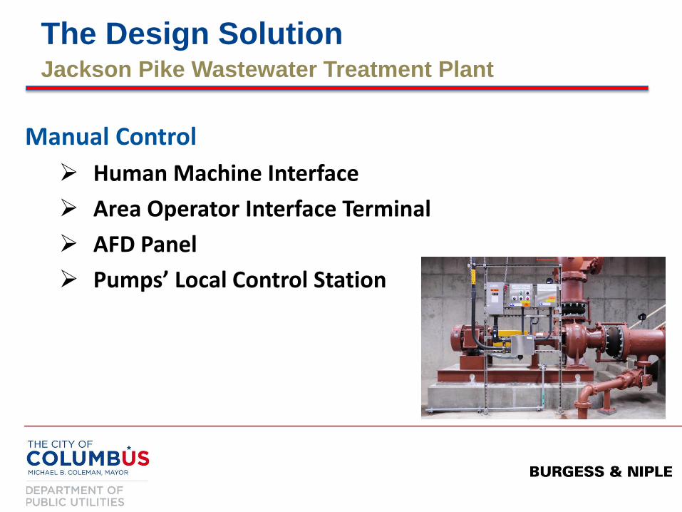
Manual Control
Human Machine Interface
Area Operator Interface Terminal
AFD Panel
Pumps’ Local Control Station
The Design Solution Jackson Pike Wastewater Treatment Plant
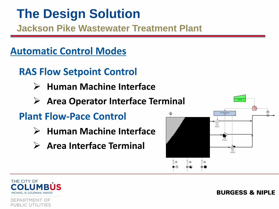
RAS Flow Setpoint Control
Human Machine Interface
Area Operator Interface Terminal
Plant Flow-Pace Control
Human Machine Interface
Area Interface Terminal
Automatic Control Modes
RAS WELL
MFIT
M
MFIT
M
MFIT
M
RAS
Pump 1
RAS
Pump 2
RAS
Pump 3
Automatic/Manual
LogicM
FIT
PID
LIT
Individual RAS Well Flow
Set Point

The Design Solution Jackson Pike Wastewater Treatment Plant
RAS Control – “Cheat Sheet”
B-Plant West RAS Well Flow Setpoints # of Pumps Needed
>12.8 MGD Not Recommended
10.3 to 12.8 MGD 3
6.2 to 10.2 MGD 2
3.5 to 6.1 MGD 1
0.1 to 3.4 MGD Not Recommended
0 MGD 0

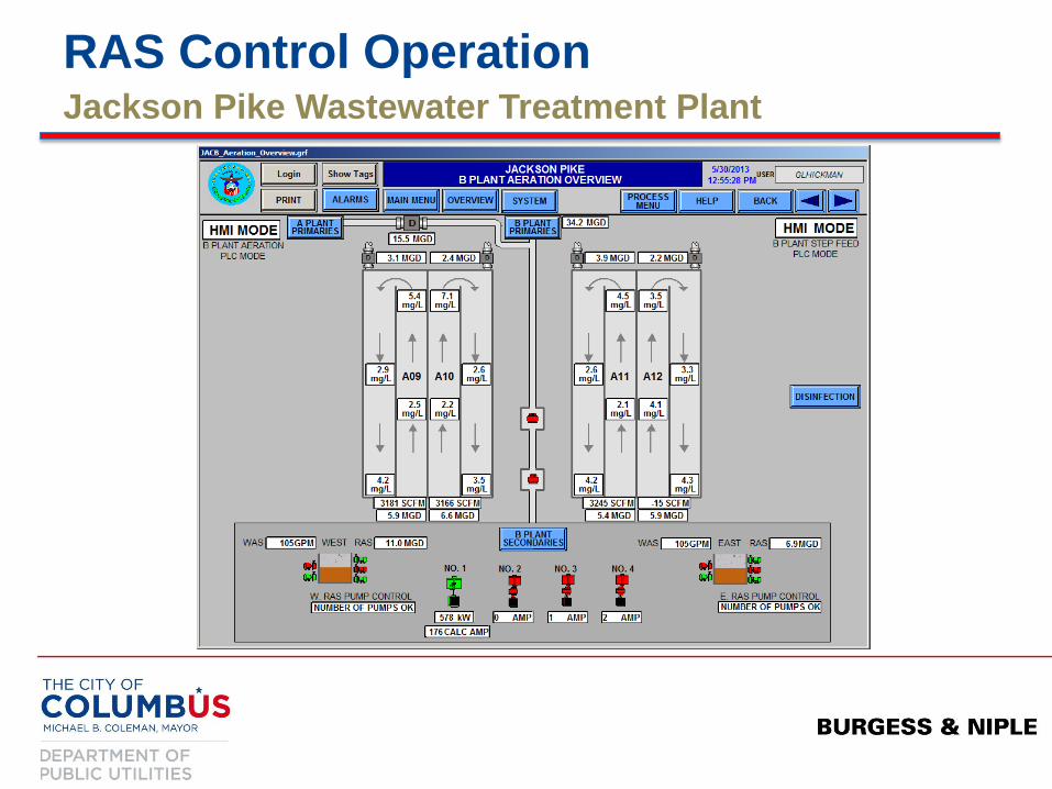
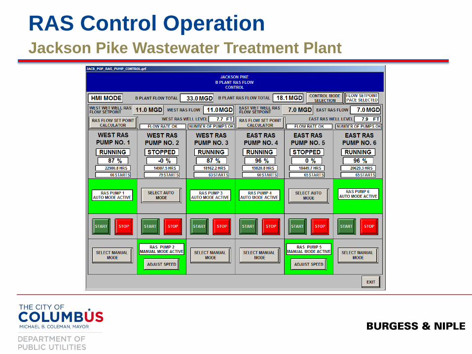
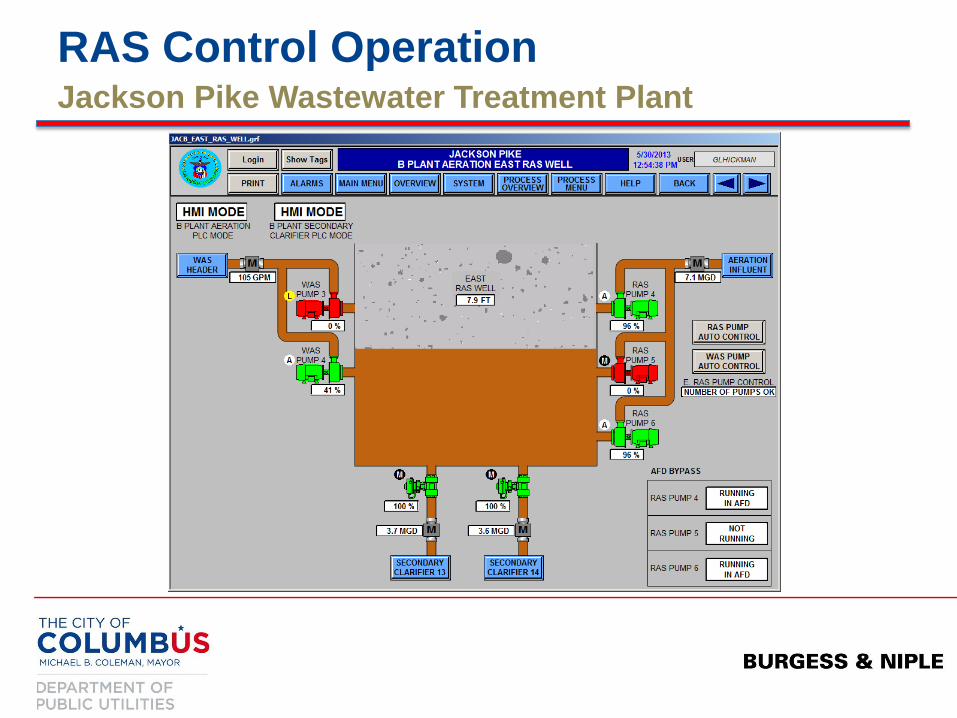
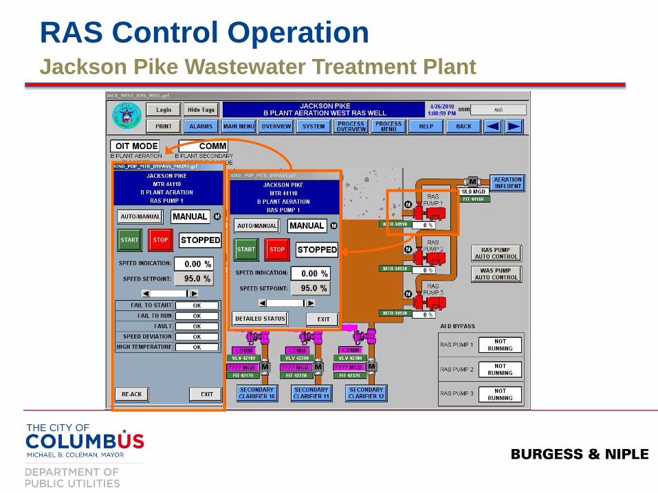
RAS Control Operation Jackson Pike Wastewater Treatment Plant
RAS Control Operation Jackson Pike Wastewater Treatment Plant
RAS Control Operation Jackson Pike Wastewater Treatment Plant
RAS Control Operation Jackson Pike Wastewater Treatment Plant

RAS Control Operation Jackson Pike Wastewater Treatment Plant
RAS Control Operation Jackson Pike Wastewater Treatment Plant

RAS Control Operation Jackson Pike Wastewater Treatment Plant
Calculator is ONLY a tool to establish RAS flow setpoints for the operator.

RAS Control Operation Jackson Pike Wastewater Treatment Plant
When the pumps are running, but NOT achieving the flow setpoint this box will either indicate: “Flow < Setpoint - Add a Pump” OR “Flow > Setpoint - Stop a Pump” Operator must ‘manually’ start or stop a pump. Then, speeds will be adjusted automatically once the appropriate number of pumps are in operation.

RAS Control Operation Jackson Pike Wastewater Treatment Plant
Why utilize such a ‘manual’ operating approach? Abrupt inflow variations experiences at plant Potential to divert flow to Southerly WWTP Informed staff influences positive reactions to plant variations Operator flexibility

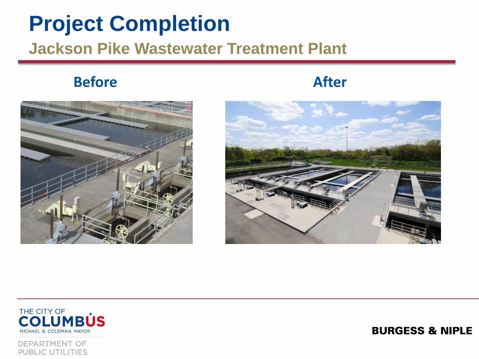
Project Completion Jackson Pike Wastewater Treatment Plant
Before After

Project Completion Jackson Pike Wastewater Treatment Plant
Before After
Project Completion Jackson Pike Wastewater Treatment Plant
Before After