
RETROFIT AND REPLACEMENT OF DUMBARTON RAILROAD BRIDGES … · · 2017-05-082.1 Criteria and...
21
RETROFIT AND REPLACEMENT OF DUMBARTON RAILROAD BRIDGES Kuan S. Go, P.E., Semyon Treyger, S.E., Michael Jones, S.E., HNTB Corporation Stephen J. Hill, Bernard Susanto, Wenlin Yang, San Mateo County Transit District Abstract The Dumbarton Rail Corridor (DRC) is located in the southern region of the San Francisco Bay Area, connecting east and west bay. The Corridor is approximately 20.5 miles in length and includes a 4.5 mile segment that crosses the southern portion of the San Francisco Bay. The crossing of the Bay includes two bridges: the Dumbarton Bridge and Newark Slough Bridge, approximately 7550 and 422 feet long, respectively. Portions of these Bridges have timber and steel truss bridge sections that are approximately 100 years old, and each has a 100-year old swing span. The existing movable bridges have not been operational since the mid-1980’s and portions of the existing timber bridges were damaged in a fire in the late 1990’s. The DRC Project proposes to provide commuter rail service by improving the existing rail infrastructure in the DRC Corridor. In order to reopen the Dumbarton and Newark Slough Bridges to accommodate the planned Dumbarton commuter rail service, several activities were performed in order to help determine if the bridges should be retrofitted or replaced. They include: Inspections (Underwater, Above Water), Concrete Coring of 100-year old large diameter caissons, Condition assessment of existing steel and concrete structures, Service Load Rating Analyses, Movable Bridge evaluation, Seismic Analyses, Constructability Review and Cost Estimates. 1. INTRODUCTION The Dumbarton Rail Corridor (DRC) is located in the southern region of the San Francisco Bay Area, connecting east and west bay. The Corridor is approximately 20.5 miles in length and includes a 4.5 mile segment that crosses the southern portion of the San Francisco Bay. The crossing of the Bay includes two bridges: the Dumbarton Bridge and Newark Slough Bridge, approximately 7550 and 422 feet long, respectively. Portions of these Bridges have timber and steel truss bridge sections that are approximately 100 years old, and each has a 100-year old swing span. The existing movable bridges have not been operational since the mid-1980’s and portions of the existing timber bridges were damaged in a fire in the 1990’s. © AREMA 2009 ®
Transcript of RETROFIT AND REPLACEMENT OF DUMBARTON RAILROAD BRIDGES … · · 2017-05-082.1 Criteria and...

RETROFIT AND REPLACEMENT OF DUMBARTON RAILROAD BRIDGES
Kuan S. Go, P.E., Semyon Treyger, S.E., Michael Jones, S.E., HNTB Corporation
Stephen J. Hill, Bernard Susanto, Wenlin Yang, San Mateo County Transit District
Abstract
The Dumbarton Rail Corridor (DRC) is located in the southern region of the San Francisco Bay
Area, connecting east and west bay. The Corridor is approximately 20.5 miles in length and
includes a 4.5 mile segment that crosses the southern portion of the San Francisco Bay. The
crossing of the Bay includes two bridges: the Dumbarton Bridge and Newark Slough Bridge,
approximately 7550 and 422 feet long, respectively. Portions of these Bridges have timber and
steel truss bridge sections that are approximately 100 years old, and each has a 100-year old
swing span. The existing movable bridges have not been operational since the mid-1980’s and
portions of the existing timber bridges were damaged in a fire in the late 1990’s.
The DRC Project proposes to provide commuter rail service by improving the existing rail
infrastructure in the DRC Corridor. In order to reopen the Dumbarton and Newark Slough
Bridges to accommodate the planned Dumbarton commuter rail service, several activities were
performed in order to help determine if the bridges should be retrofitted or replaced. They
include: Inspections (Underwater, Above Water), Concrete Coring of 100-year old large diameter
caissons, Condition assessment of existing steel and concrete structures, Service Load Rating
Analyses, Movable Bridge evaluation, Seismic Analyses, Constructability Review and Cost
Estimates.
1. INTRODUCTION
The Dumbarton Rail Corridor (DRC) is located in the southern region of the San Francisco Bay
Area, connecting east and west bay. The Corridor is approximately 20.5 miles in length and
includes a 4.5 mile segment that crosses the southern portion of the San Francisco Bay. The
crossing of the Bay includes two bridges: the Dumbarton Bridge and Newark Slough Bridge,
approximately 7550 and 422 feet long, respectively. Portions of these Bridges have timber and
steel truss bridge sections that are approximately 100 years old, and each has a 100-year old
swing span. The existing movable bridges have not been operational since the mid-1980’s and
portions of the existing timber bridges were damaged in a fire in the 1990’s.
© AREMA 2009 ®

The existing Dumbarton and Newark swing steel truss bridges and piers were constructed in
1910. The original construction included: ballasted deck timber trestle at the west approach; steel
deck girders and steel through truss with a swing span at the channel crossing; and ballasted deck
timber trestle at the east approach. While the entire structure has a single railroad track, the steel
spans were built for two parallel tracks. Sections of the approach spans have been modified and
rebuilt in the 1960s and 1970s with precast concrete construction.
The DRC Project proposes to provide commuter rail service by improving the existing rail
infrastructure in the DRC Corridor. In order to reopen the Dumbarton and Newark Slough
Bridges to accommodate the planned Dumbarton commuter rail service, the San Mateo County
Transit District (SAMTRANS) engaged HNTB to perform preliminary engineering in support of
the environmental document to help determine if the bridges should be retrofitted or replaced.
2. BACKGROUND
The engineering team evaluated the original concrete piers and steel trusses to determine the
feasibility of retrofit/rehabilitation of the structures for the proposed Dumbarton Rail service. See
Figures 1, 2 and 3 for location and configuration of the existing bridges.
© AREMA 2009 ®

Figure 1. Location Map
© AREMA 2009 ®

Figure 2. Dumbarton Main Span - Swing Span and Steel Trusses (Section 4 to 9)
Figure 3. Newark Slough Swing Span
© AREMA 2009 ®

2.1 Criteria and Constraints
Recent updates to seismic and AREMA railroad criteria pose new design and analyses challenges
on the existing bridges. In addition, the structural integrity of the 100 year old caissons is largely
unknown to validate the conceptual studies performed thus far. Finally, construction in the San
Francisco Bay posses several constraints. These constraints include water quality, biological,
protection of endangered species, mammals and considerations of marine, bird and other wildlife
breeding and nesting seasons.
2.2 Work Plan
The work plan (Figure 4) below presents the relationships between different activities and how
each activity relates to another in order to meet the project objective of identifying a preferred
alternative of retrofitting or replacing the Dumbarton Bridges.
Figure 4. Work Plan for Retrofit and Replacement of Dumbarton Railroad Bridges
3. INSPECTIONS
From November 2007 to January 2008, HNTB engineers and inspectors and Halcrow underwater
divers-inspectors conducted inspections of the existing bridges and its supporting piers. CTL
Group concrete specialists obtained concrete coring samples of the existing concrete caissons.
© AREMA 2009 ®

3.1 Caisson Inspections
Over several days in November and December 2007, a three-person experienced engineer-diver
team conducted detailed above-water and underwater inspections of 22 concrete caissons
supporting the spans at the Dumbarton Rail Bridge and 5 concrete caissons of the bridge at the
Newark Slough. These existing caissons were built as part of the original steel trusses
construction in 1910. All caissons exhibit a zone of corrosion in the steel casing, typically
ranging from 1-ft above the Mean Low Water (MLW) elevation to 10-ft below the MLW
elevation. Approximately 60% of the steel in that zone has moderate to severe corrosion with
areas of exposed concrete. The condition of the exposed concrete varies widely, from minor
surface deterioration, to large voids with soft concrete and exposed timber piles (see Figures 5, 6
and 7).
Overall structural integrity of the original caissons is affected by large areas of spalling with
deep voids at the caissons, particularly the voids with exposed timber piles. Since a majority of
the steel shells at the caissons are still intact, it is impossible to determine the overall extent of the
deterioration of the concrete.
Figure 5. Dumbarton Pier 6, Northwest Caisson, SE Quadrant, 9.5-ft below MLW Typical Steel in the 1-ft above to 10-ft below MLW, Typical Condition of Steel Shell.
© AREMA 2009 ®

Figure 6. Dumbarton Pier 6, Northwest Caisson, SW Quadrant, 6.5-ft below MLW with Large Void (28’W X 2.3’H X 5’D) in Caisson
Figure 7. Dumbarton Pier 6, Northwest Caisson, SE Quadrant, Large Spall with Exposed Timber Pile
© AREMA 2009 ®

3.2 Steel Trusses and Swing Bridges Inspections
The Dumbarton and Newark Swing Bridges are open deck swing spans which opened to traffic in
1910. The span lengths for Dumbarton and Newark swing spans are 310-ft and 182-ft,
respectively. Six 180-ft span steel trusses approach to the Dumbarton swing span from east and
west. The structures have not seen any rail traffic since the mid 1980s.
Light to moderate blanket rust is present on almost all truss members as the protective paint
system has failed. Pack rust is found under most connection plates, top surfaces of top and bottom
chords and end posts. The floor system (floorbeams and stringers) and cross girders have
extensive corrosion and severe section loss in several locations. The severity of the section loss
and pack rust found in the floor system and connections warrants their replacement. All of the
secondary members (laterals) and their connection gusset plates have substantial section loss and
severe corrosion which warrants replacement of these members in their entirety. (See Figures 8,
9, 10 and 11 for bridge conditions).
© AREMA 2009 ®

Figure 8. Dumbarton Bridge - Typical Failed Paint on Truss Member
Figure 9. Dumbarton Bridge - Typical Corrosion and Pack Rust of Steel Truss Member
© AREMA 2009 ®

Figure 10. Dumbarton Swing Span – View of Floor Beam
Figure 11. Newark Swing Span - View of Floor Beam and Pier Top
© AREMA 2009 ®

3.3 Concrete Coring
In January 2008, structural concrete specialists took concrete core samples from the concrete
caissons that support the original steel trusses. A total of nine deep concrete core samples were
taken with depths ranging from 16 to 72 feet from the top of caissons.
Concrete conditions were remarkably consistent for all cores drilled. Concrete in upper
portions of the caissons (upper 12 to 14 feet), extending to approximately the tidal fluctuation
zone consisted of good quality concrete (See Figure 12).
Concrete samples extracted from the tidal fluctuation zone (region at water line and below)
were less sound and of lower quality. Cement paste was very soft and often washed away from
the core surface, leaving exposed aggregate (See Figure 13). This condition is consistent with a
concrete mix of very high water to cement ratio. In several locations, sample lengths consisting of
only cement paste were extracted (See Figure 14). This condition is consistent with segregation of
the mix during original concrete/cement placement.
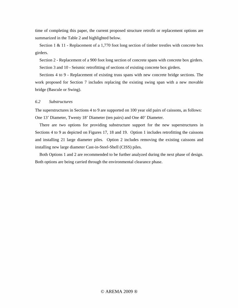
Below the tidal fluctuation zone, concrete quality was poor, typically disintegrating to rubble
during coring. At the main span center pier core hole, concrete quality was poor from the tidal
fluctuation zone and below (See Figure 15 and 16).
Based on preliminary observations, it is believed that the poor quality of the concrete in the
lower portions of the caissons is due to washout of the cement paste during original construction.
Historical ASCE papers (Schneider 1913) describing the bridge construction indicate that
concrete was simply dumped into the caissons in still water conditions, as was customary at the
time.
© AREMA 2009 ®

Figure 12. Typical Concrete Core Samples, Upper Portions of Piers
Figure 13. Typical Concrete Sample From Tidal Fluctuation Zone
© AREMA 2009 ®
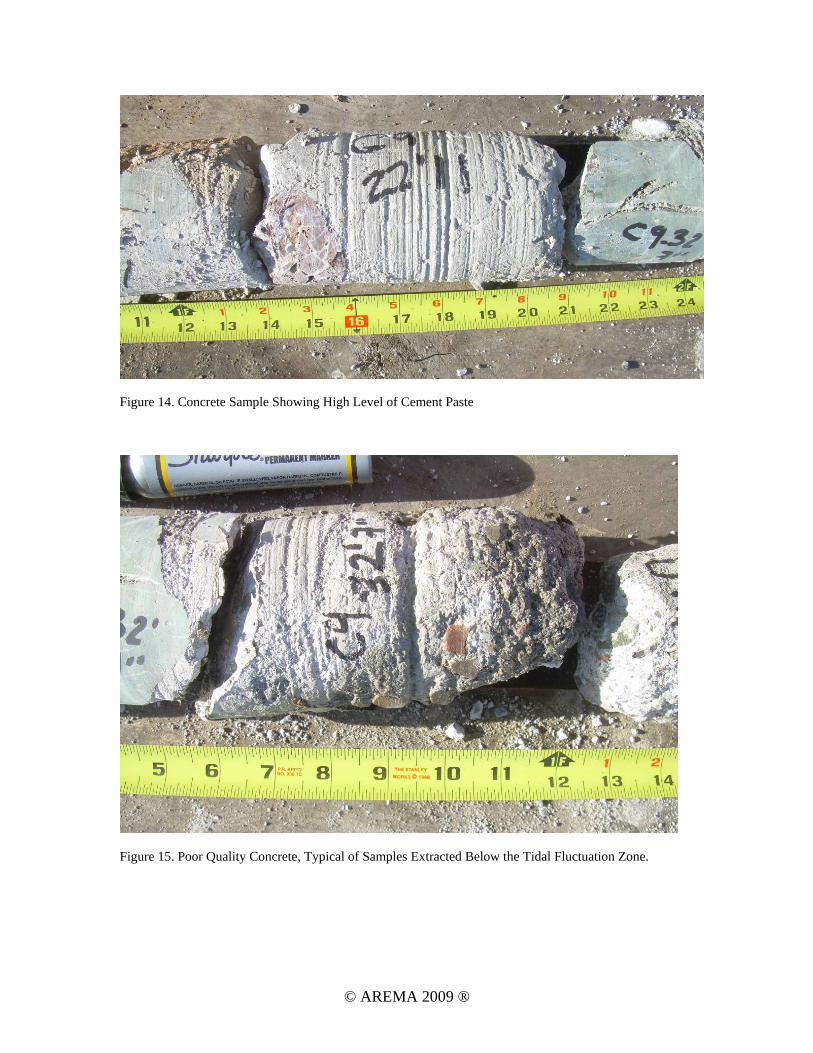
Figure 14. Concrete Sample Showing High Level of Cement Paste
Figure 15. Poor Quality Concrete, Typical of Samples Extracted Below the Tidal Fluctuation Zone.
© AREMA 2009 ®

Figure 16. Rubble – Aggregate is Very Clean, With Very Little Cement Paste on Surface. Typical of Samples Extracted Below the Tidal Fluctuation Zone
4. LOAD RATING ANALYSES
A two dimensional computer model was created to complete a load rating evaluation for the six
Dumbarton steel through truss spans and swing span. The analysis and modeling was performed
using a proprietary program called T187, a structural analysis computer program developed by
HNTB. The analysis focused on the vertical load resisting members within the truss and floor
system. The result of the examination contains load ratings for the top and bottom chords,
hangers, diagonals, floorbeams and stringers.
Using information from existing drawings and field measurements, member section properties
and dead loads were calculated with Excel spreadsheets. Member section properties were
adjusted to account for effects of corrosion in the bridge members. These modified section
properties were incorporated in the computer model for the dead and live load analysis. Results of
the computer analysis were used to carry out the load rating evaluation, which was done in
conformance with the 2007 American Railway Engineering and Maintenance-of-way Association
(AREMA) Manual.
The new rail corridor is expected to be a single track designed for Cooper E-80 loading.
Results from the load rating evaluation demonstrated that all vertical load resisting truss and floor
© AREMA 2009 ®

system elements can safely support a Cooper E-80 loading, with the exception of the stringers and
end floorbeams. Their reduced load rating is primarily due to section loss of the members from
corrosion. However, the stringers and all floorbeams exceed their fatigue category stress range.
For this reason, it is recommended that the stringers and all floorbeams be replaced if the existing
steel through trusses were reused for the new rail corridor. The main truss members can be
reused.
The load rating of the existing concrete spans indicate that they are capable of supporting a
Cooper E-72 train loading, which they were originally designed for.
5. SEISMIC ANALYSES
5.1 Seismic Design Criteria
Project specific performance-based design criteria (Criteria) are under development for the
Dumbarton Bridge. The principle design code reference is the 2007 edition of the AREMA
Manual for Railway Engineering [AREMA 2007]. Criteria stipulated that the structure must
comply with specified performance levels for two distinct seismic levels, an upper level seismic
event with a mean return period of 1000 years that corresponds to the Survivability Limit State in
AREMA and a lower level event with a mean return period of 91 years that corresponds to the
AREMA Serviceability Limit State. At the time of writing this report Criteria was incomplete, but
it is anticipated that Criteria will eventually specify the following:
• Allowable damage levels for each seismic demand level
• Material strain or force limits for each damage levels
• Drift and/or residual displacement limits
• Required analysis assessment procedures
• Methodology to consider seismic hazards
5.2 Seismic Analyses of Dumbarton Main Channel Structures
The existing Dumbarton Rail Corridor Bridge substructure is comprised of four unique
construction types, designated as Segments 1 through 4 (See Table 1 below). Segment 1 consists
of timber trestles; Segment 2 consists of 4-pile concrete bents; Segment 3 consists of 2-pile
concrete bents; and Segment 4, the navigational channel, is constructed with large diameter
concrete caissons.
© AREMA 2009 ®

Seismic finite element models were prepared incrementally using FE ADINA computer
program recognizing that the Dumbarton Bridge is comprised of four unique segments as
described in Table 1. For each segment, stand-alone models of individual bents were first
prepared. These stand-alone models were useful for a number of reasons including checking
modeling techniques used for global models, performing pushover analyses, and performing
parametric studies of alternate retrofit strategies. Additionally, since superstructure flexural
continuity was not provided across bents, the transverse responses of the stand-alone models are
representative of the transverse response of the global bridge.
Global models only considered the portion of the structure extending from the West Abutment
to the easterly end of the navigational channel, or the end of Segment 4 shown in Table 1. The
total length of this portion of the structure is 6597 ft.
5.3 Recommended Seismic Strategy
The recommended seismic retrofit strategy for each of the four segments is as follows:
Segment 1, Timber Trestles – The existing timber trestles will be replaced with new
construction.
Segment 2, 4-Pile Concrete Bents – These existing bents have numerous deficiencies including
insufficient displacement capacity, inadequate bent cap strength, shear deficiencies in concrete
piles, plastic hinges requiring retrofit below the mudline, and deficient shear keys. In
Table 1 – Division of Dumbarton Bridge Into Four Segments by Bent Types
Segment Bents Length (ft) Description
Model Properties No. of Nodes
No. of Elements
1 1-60 1770 2New 30 ft concrete box girder spans with 42 in. precast/prestressed concrete 3-pile bents 3709 3768
2 61-89 900 Existing 30 ft concrete box girder spans with 24 in. precast/prestressed concrete 4-pile bents 2967 3163
3 90-142 2340 Existing 45 ft concrete box girder spans with 48 in. precast/prestressed concrete 2-pile bents 3327 4119
4 143-159 1587 Existing navigational channel with superstructure replaced and new intermediate bents added
44391 44691
1, 2, 3 & 4 1-159 6597 Segments 1, 2, 3, and 4 combined into global model 14,459 15,123
1Properties of Retrofit Option 1 2Subsequent to configuring retrofit models, spans for Segment 1 were increased to 60 ft. Four-pile super bents were added so that the longitudinal stiffness of the 30 ft and 60 ft spans remained essentially identical, thus not affecting the retrofit assessment.
© AREMA 2009 ®

consideration of these numerous deficiencies, replacement of the existing 30’ spans with longer
spans is recommended.
Segment 3, 2-Pile Concrete Bents – Retrofit is recommended at Segment 3. The existing 48 in.
hollow PC/PS concrete piles have sufficient displacement capacity to avoid retrofit to the piles
below the mudline, with the exception of inserting isolation casings over the piles at selected
locations. To increase ductility of piles at the connection to the pilecap in the transverse direction,
a composite wrap is recommended. However, the composite wrap can be economically placed
above the water level. Bent caps have sufficient strength to respond as capacity-protected
members. The recommended retrofit at the bent cap is the addition of shear keys to ensure
adequate transfer of forces between the superstructure and substructure.
Segment 4, Navigational Channel – Two retrofit options are recommended for further study.
Option 1 requires the replacement of the superstructure, but retrofits the existing large diameter
caissons with new piling and a concrete shell around the full circumference of the caissons.
Additionally, to avoid the need to match the existing 180 ft superstructure spans, new
intermediate bents will be added between caissons to reduce spans other than the moveable span
to a maximum length of approximately 92-ft. Option 2 calls for the full replacement of all
substructure and superstructure elements.
Of the two retrofit options, Option 1 provided the advantage of stiffening the entire structure
and permitting the retrofit and reuse of Segment 3. This was due to the much greater stiffness of
the retrofitted caissons. Since there are a number of considerations other than seismic
performance that will influence the selection of replacement or rehabilitation of the existing
substructure at Segment 4, it is recommended to continue studying both options and defer the
selection of the preferred option until the regulatory agencies have commented on the two
options.
6. PROPOSED SCOPE OF FUTURE RETROFIT OR REPLACEMENT
6.1 General
The summary of the proposed scope of the work in order to bring the existing bridge to current
AREMA standards is based on the engineering studies completed to date. The studies included
inspections, condition assessment and load ratings, seismic analyses, constructability review, and
cost estimates. The work has been subjected to extensive peer reviews by SAMTRANS
engineering staff and consultants. This scope of work could change in the future, based on
continuing refinements, engineering studies and meeting regulatory agency requirements. At the
© AREMA 2009 ®
time of completing this paper, the current proposed structure retrofit or replacement options are
summarized in the Table 2 and highlighted below.
Section 1 & 11 - Replacement of a 1,770 foot long section of timber trestles with concrete box
girders.
Section 2 - Replacement of a 900 foot long section of concrete spans with concrete box girders.
Section 3 and 10 - Seismic retrofitting of sections of existing concrete box girders.
Sections 4 to 9 - Replacement of existing truss spans with new concrete bridge sections. The
work proposed for Section 7 includes replacing the existing swing span with a new movable
bridge (Bascule or Swing).
6.2 Substructures
The superstructures in Sections 4 to 9 are supported on 100 year old pairs of caissons, as follows:
One 13’ Diameter, Twenty 18’ Diameter (ten pairs) and One 40’ Diameter.
There are two options for providing substructure support for the new superstructures in
Sections 4 to 9 as depicted on Figures 17, 18 and 19. Option 1 includes retrofitting the caissons
and installing 21 large diameter piles. Option 2 includes removing the existing caissons and
installing new large diameter Cast-in-Steel-Shell (CISS) piles.
Both Options 1 and 2 are recommended to be further analyzed during the next phase of design.
Both options are being carried through the environmental clearance phase.
© AREMA 2009 ®

Table 2 – Dumbarton Bridge Scope as of June 15, 2009
Figure 17 – Proposed Scope at Sections 4 to 11.
1 and 11 2 3 and 10Option Name --------------- --------------- --------------- Option 1 (Retrofit) Option 2 (Replace)
Existing Structure Timber Trestle (portions burnt)
PC/PS Box Girder Spans on 4-Pile-Bents
PC/PS Box Girder Spans on 2-Pile-Bents
Main Channel Movable, Steel Thru Truss, and Transition Spans on Large Diameter Caissons
Main Channel Movable, Steel Thru Truss, and Transition Spans on Large Diameter Caissons
Proposed Structure New Concrete Spans Replace with Concrete Spans
Seismic Retrofit Existing Structures
Replace Superstructure with New Movable Bridge and 92' Concrete Spans
Replace Superstructure with New Movable Bridge and 112' Concrete Spans
- Retrofit 11 caissons (1-40', 9-18', 1-13')- Leave 9 caissons in place and remove 2- Add: Seven new intermediate supports
- Remove All Caissons, - New Supports with Driven Piles
Approx. 1~2 months in-water construction
Approx. 24~28 months in-water construction
Approx. 30~36 months in-water construction
Pile Driving- Pile Type- # Piles - Length/Pile
4' PC/PS pile 114 piles 110'/pile
4' PC/PS pile 36 piles 110'/pile
N/A 4.5' PC/PS, 3' steel, 4' steel piles21, 120, 12 piles125', 150', 150'/pile
6.0' CISS pile 54 piles 130'/pile
Total Piles / Length 114 piles/12,540 ft 36 piles/3,960 ft 153 piles/22,425 ft 54 piles/7,020 ft
Concrete in the Bay* - Existing 30 cubic yards 188 cubic yards 1322 cubic 14,959 cubic yards 14,959 cubic yardsChange + 513 cubic yards +43 cubic yards 0 cubic yards +10,373 cubic yards decrease 11,447 cubic
yardsTotal 543 cubic yards 231 cubic yards 1322 cubic yards 25,332 cubic yards 3,512 cubic yards
Fill in the Bay* - Net Change 4200 cubic yards 1365 cubic yards 148 cubic yards 4271 cubic yards 1365 cubic yards
Note: PC/PS pile - Precast / Prestressed Concrete PileCISS pile - (Concrete) Cast-In-Steel-Shell Pile"Concrete in the Bay" quantities include substructure from top of pile to mudline only (no superstructure included)"Fill in the Bay" quantities include net change of substructure volume from mudline to bottom of pile only
In-Water Construction Duration(With in-water restrictions)
4 through 9SECTIONS
Approx. 30~36 months in-water construction
© AREMA 2009 ®

Figure 18 – Option 1 (Retrofit) at Dumbarton Main Channel Substructure
Figure 19 – Option 2 (Replacement) at Dumbarton Main Channel Substructure
© AREMA 2009 ®

7. CONCLUDING REMARKS
The engineering work performed on the Dumbarton Railroad Bridges has helped SAMTRANS
determine the scope, constructability, cost and challenges of retrofitting or replacing the Bridges.
It has also helped the environmental scientists determine the environmental impacts of the
proposed retrofit or replacement of the Bridges. SAMTRANS will be circulating a draft
environmental impact statement and environmental impact report (DEIS/R) on the DRC project
in summer 2009. The decision on retrofit or replacement of the Dumbarton Railroad Bridges will
depend on several factors including project cost, environmental impacts, constraints and public
and agency reviews and comments. SAMTRANS will identify a Locally Preferred Alternative
(LPA) including whether the Bridges will be retrofitted or replaced by the end of 2009.
REFERENCES Schneider, E. J. 1913. Construction Problems, Dumbarton Bridge, Central California Railway,
Transactions of the American Society of Civil Engineers, March 19, 1913. Paper No. 1271, 1573-1623 American Railway Engineering and Maintenance-of-Way Association (AREMA) (2007). Manual for
Railway Engineering, Lanham, Maryland.
© AREMA 2009 ®


![082.1-1a mod. 1- LPM.ppt [modalità compatibilità] · 2013. 2. 20. · 082.1-1a mod. 1-LPM.ppt v_120301 Il basamento, sia a pianta circolare che quadrangolare, è costituito da strati](https://static.fdocuments.net/doc/165x107/602c0914d7971368ba6f2b9b/0821-1a-mod-1-lpmppt-modalit-compatibilit-2013-2-20-0821-1a-mod.jpg)
