Results from the In Situ Fault Slip Experiment at Mont Terri · Local Factor of 106-to-107...
27
Results from the In Situ Fault Slip Experiment at Mont Terri Yves Guglielmi, Jens T. Birkholzer, Jonny Rutqvist, Pierre Jeanne Lawrence Berkeley National Laboratory U.S. Department of Energy National Energy Technology Laboratory Mastering the Subsurface Through Technology Innovation, Partnerships and Collaboration: Carbon Storage and Oil and Natural Gas Technologies Review Meeting August 1-3, 2017
Transcript of Results from the In Situ Fault Slip Experiment at Mont Terri · Local Factor of 106-to-107...

Results from the In Situ Fault Slip Experiment at Mont Terri
Yves Guglielmi, Jens T. Birkholzer,
Jonny Rutqvist, Pierre Jeanne
Lawrence Berkeley National Laboratory
U.S. Department of Energy
National Energy Technology Laboratory
Mastering the Subsurface Through Technology Innovation, Partnerships and Collaboration:
Carbon Storage and Oil and Natural Gas Technologies Review Meeting
August 1-3, 2017
2
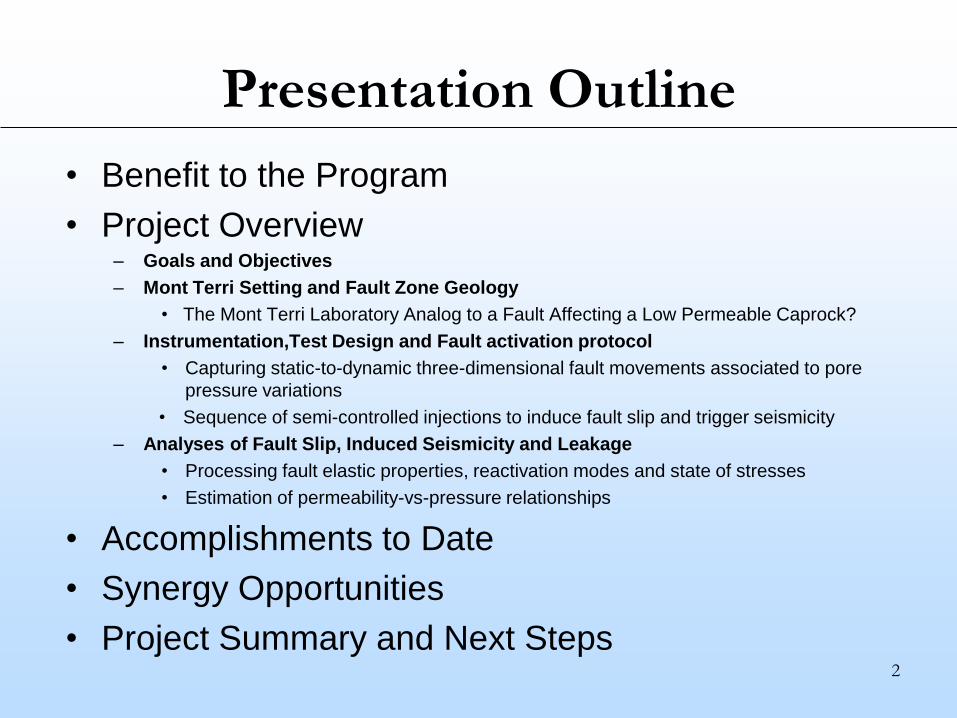
Presentation Outline
• Benefit to the Program
• Project Overview– Goals and Objectives
– Mont Terri Setting and Fault Zone Geology
• The Mont Terri Laboratory Analog to a Fault Affecting a Low Permeable Caprock?
– Instrumentation,Test Design and Fault activation protocol
• Capturing static-to-dynamic three-dimensional fault movements associated to pore
pressure variations
• Sequence of semi-controlled injections to induce fault slip and trigger seismicity
– Analyses of Fault Slip, Induced Seismicity and Leakage
• Processing fault elastic properties, reactivation modes and state of stresses
• Estimation of permeability-vs-pressure relationships
• Accomplishments to Date
• Synergy Opportunities
• Project Summary and Next Steps

3
Benefit to the Program
• This project improves and tests technology to assess
and mitigate potential risk of induced seismicity as a
result of injection operations.
• The technology improves our understanding of fault slip
processes and provides new insights into the seismic
and leakage potential of complex fault zones.
This contributes to Carbon Storage Program’s effort:
– to ensure for 99% CO2 storage permanence
– to predict CO2 storage capacity in geologic formations to within
±30 percent
4
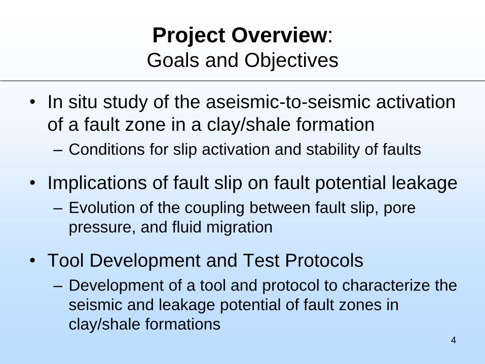
Project Overview: Goals and Objectives
• In situ study of the aseismic-to-seismic activation
of a fault zone in a clay/shale formation
– Conditions for slip activation and stability of faults
• Implications of fault slip on fault potential leakage
– Evolution of the coupling between fault slip, pore
pressure, and fluid migration
• Tool Development and Test Protocols
– Development of a tool and protocol to characterize the
seismic and leakage potential of fault zones in
clay/shale formations

5
A Fault Affecting a Low-Permeable Layer
Analog to a Reservoir Cap Rock
Mont Terri Underground Rock Laboratory
swisstopo
Depth of FS Experiment ~350m

6
Fault Zone Structure and ComplexityA ~3m-thick core with gouge + foliation + secondary (Riedel-like) shear planes
A damage zone with secondary fault planes with slickensided surfaces
Gouge
2 cm
1 m
50m
Fault Core
Secondary fault surface
in the fault damage zone
The unaltered structure of the
Main Fault has been accessed
through gallery outcrops and fully
cored boreholes
5 cm
Opalinus Clay
2 microns
7
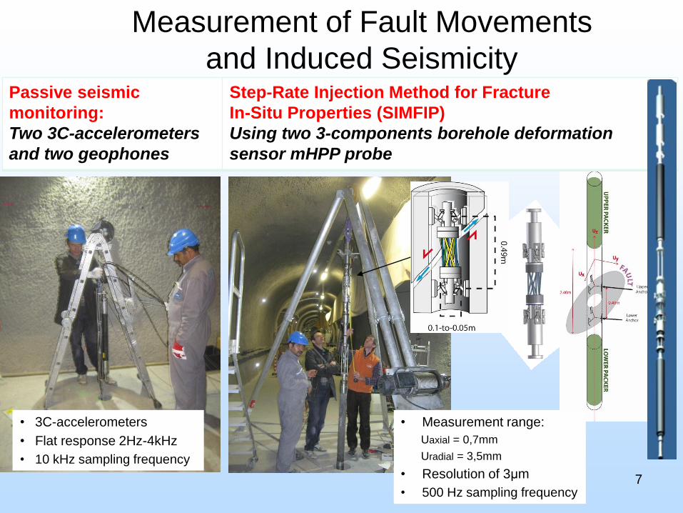
Passive seismic
monitoring:
Two 3C-accelerometers
and two geophones
Step-Rate Injection Method for Fracture
In-Situ Properties (SIMFIP)
Using two 3-components borehole deformation
sensor mHPP probe
Measurement of Fault Movements
and Induced Seismicity
• Measurement range:
Uaxial = 0,7mm
Uradial = 3,5mm
• Resolution of 3μm
• 500 Hz sampling frequency
• 3C-accelerometers
• Flat response 2Hz-4kHz
• 10 kHz sampling frequency
8
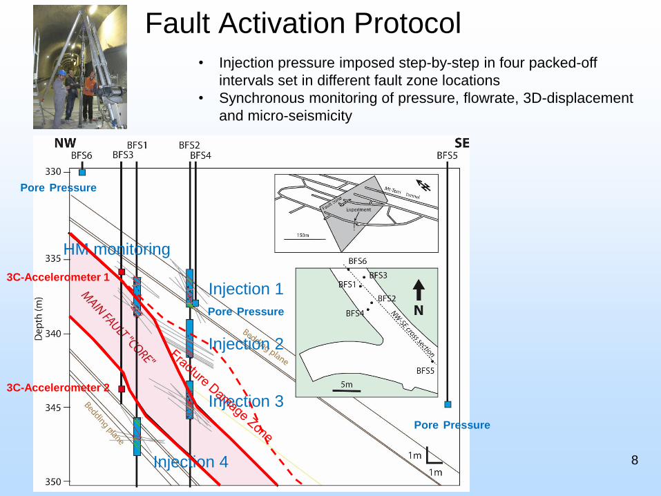
Fault Activation Protocol
• Injection pressure imposed step-by-step in four packed-off
intervals set in different fault zone locations
• Synchronous monitoring of pressure, flowrate, 3D-displacement
and micro-seismicity
Injection 1
Injection 2
Injection 3
Injection 4
3C-Accelerometer 1
3C-Accelerometer 2
HM monitoring
Pore Pressure
Pore Pressure
Pore Pressure

Example of Borehole Pressure-Displacement signals
Pa
cke
r
3D displacement
sensor
• Pressure imposed
step-by-step
• Monitoring
Injection Flowrate
+
Borehole wall
3D displacement
Fault Opening Pressure (FOP)
X
Z
Y

Large Fault leakage at failure in shear
FPP : Fault Propagation Pressure
FOP :Fault Opening Pressure
Example Test at 340.6m depth in Clay Fault Mt Terri URL (Switzerland)

Pressure (Mpa)
Different modes of reactivation In and Out of the fault zone
Host rock : Mainly Dilatant - Normal Opening
Main Fault Interface: Mainly Shear - Slip
?
Measured Plastic Vectors
Test 37.2m
Test 40.6m
• Shear failure (slip) mainly along
the Fault Core - FDZ interface
Dis
pla
cem
ent
(mm
)
SH
SH

Pressure (Mpa)
Role of Contrasted Elastic Modulus (and fracture toughness)
Modulus of Deformation (GPa)
HR
HFR
FDZ
FC
FDZ
Emax
• E fault core ~ E host Rock / 10
• From bedding influence
to fracture influence
HFR
HR
FDZ
FC
𝜀 =1+𝜈
𝐸× 𝛥𝑃𝑓
(Jeanne et al., accepted 2017)
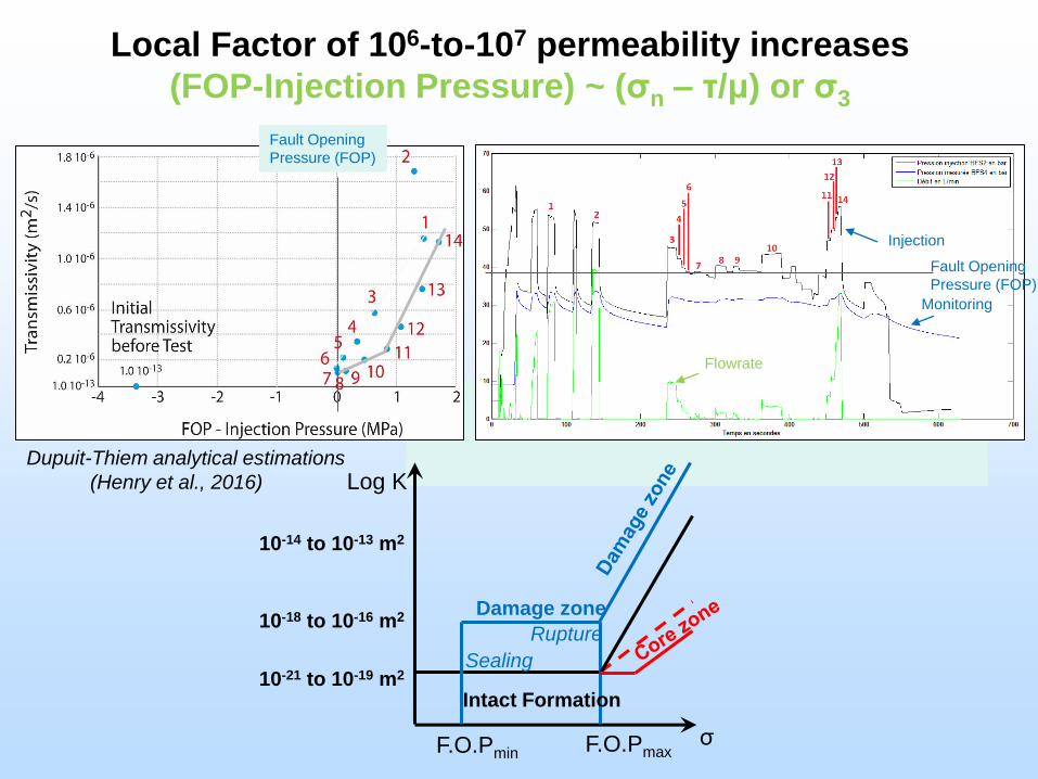
Local Factor of 106-to-107 permeability increases
(FOP-Injection Pressure) ~ (σn – τ/μ) or σ3
Dupuit-Thiem analytical estimations
(Henry et al., 2016)
Fault Opening
Pressure (FOP)
Injection
Flowrate
Monitoring
Fault Opening
Pressure (FOP)
Rupture
Sealing
F.O.Pmax
Intact Formation
Damage zone
σ
Log K
10-18 to 10-16 m2
10-21 to 10-19 m2
10-14 to 10-13 m2
F.O.Pmin

Comparison with Barbados active decollement fault
• Comparable behaviorsand orders of magnitude
• Thresholdcould in bothcases correspond to shearactivation
Intact formation
10-19 – 10-18 m2
FOP
(Ficher and Zwart, 1997)
15
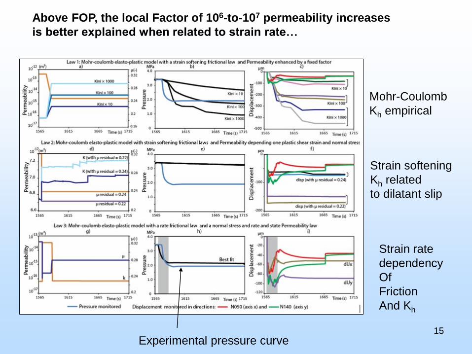
Above FOP, the local Factor of 106-to-107 permeability increases
is better explained when related to strain rate…
Mohr-Coulomb
Kh empirical
Strain softening
Kh related
to dilatant slip
Strain rate
dependency
Of
Friction
And Kh
Experimental pressure curve

Aseismic slip preceeding Leakage and Seismicity
Seismic Source radius ~ 1.2m
Pressurized zone radius ~ 10m
Injection
Main Fault
Mw ~ -2.5
Pressurized patch is
Larger than seismic patch
Example Test at 340.6m depth in Clay Fault Mt Terri URL (Switzerland)

Accomplishments to Date• A unique fault reactivation data set has been generated
characterized by synchronous monitoring of fault movement,
induced earthquakes, pore pressure, and injection flowrate
• A new measurement tool and a test protocol have been
developed to characterize, in a controlled field setting, the seismic
and leakage potential of fault zones
• Comparison with other field activation experiments and natural
active fault leakage
observations
17

Synergy Opportunities
• The SIMFIP Probe
is now being upgraded for higher pressure
and temperature environments
• It will be operated to monitor hydrofracking
and hydroshearing experiments planned
in the EGS-Collab project SIGMA-V
18
• Operating pressure 40MPa
• Measurement range:
Uaxial = 0,7mm
Uradial = 3,5mm
• Resolution of 5μm
• 1000 Hz sampling frequency

Summary
Key Findings
19
• Insights on the seismic nucleation phase common to all experiments
– Large patch of aseismic slip associated with high dilation
– High increase in permeability (mainly in the Fault Damage Zone)
• With effective Coulomb stress
• With Dilatant Shear strain « rate » distributed in the Fault Zone
volume
(which drives a « sparse » seismicity)
• Location and Origin of seismicity induced by fluid injections?
A combination of fracture mechanics and earthquake nucleation
concepts
- Effect of strength + permeability properties variations in the fault zone
- Accelerated creep with large dilation could cause a frictional
transition (and episodic instability)

20
Future Plans
• Develop and calibrate a physics based fully coupled hydromechanical approach for
predictions of seismic-to-aseismic fault rupture and leakage at CO2 sequestration
depths (considering dilation in contact-yielding concepts?)
• Evaluate and measure potential for long-term fault sealing capabilities in cap-rocks
• New FS-B experiment : Test of existing techniques of repeated active seismic imaging,
passive microseismic and strain monitoring to characterize and to monitor fault slip and
long term leakage evolution.

Relevance to SubTER Crosscut
EnergyFieldObservatories
FitForPurposeSimulationCapabilities
IntelligentWellboreSystems
SubsurfaceStress&InducedSeismicity
PermeabilityManipulation
NewSubsurfaceSignals
Remediationtoolsandtechnologies
Fit-for-purposedrillingandcompletiontools
(e.g.anticipativedrilling,centralizers,monitoring)
HT/HPwellconstruction/completiontechnologies
Measurementofstressandinducedseismicity
Manipulationofstressandinducedseismicity
Relatingstressmanipulationand
inducedseismicitytopermeability
Appliedriskanalysisofsubsurfacemanipulation
Physicochemicalfluid-rockinteractions
Manipulatingflowpaths
Characterizingfractures,dynamics,andflows
Novelstimulationmethods
Newsensingapproaches
Integration
ofmulti-scale,multi-typedata
Adaptivecontrolprocesses
Diagnosticsignaturesandcriticalthresholds
Newdiagnosticsforwellboreintegrity
Autonomouscompletionsforwellintegrity
modeling
Improvedwellconstructionmaterials
andtechniques
Subsurface Stress and Induced Seismicity Pillar
is relevant to a range of subsurface applications

Appendix
– These slides will not be discussed during the presentation, but
are mandatory.
22

23
Benefit to the Program
• This project improves and tests technology to assess
and mitigate potential risk of induced seismicity as a
result of injection operations.
• The technology improves our understanding of fault slip
processes and provides new insights into the seismic
and leakage potential of complex fault zones.
This contributes to Carbon Storage Program’s effort:
– to ensure for 99% CO2 storage permanence
– to predict CO2 storage capacity in geologic formations to within
±30 percent

24
Project Overview: Goals and Objectives
• In situ study of the aseismic-to-seismic activation
of a fault zone in a clay/shale formation
– Conditions for slip activation and stability of faults
• Implications of fault slip on fault potential leakage
– Evolution of the coupling between fault slip, pore
pressure, and fluid migration
• Tool Development and Test Protocols
– Development of a tool and protocol to characterize the
seismic and leakage potential of fault zones in
clay/shale formations

25
Organization Chart
• Project participants: International Collaborations
– Yves Guglielmi (LBNL, USA) – PI – Field test analyses, tool and
protocol development
– Jonny Rutqvist , Jens Birkholzer, Pierre Jeanne (LBNL, USA) –
Hydromechanical modeling
– Christophe Nussbaum (Swisstopo, Switzerland) – Fault structure,
kinematics and stress analyses
– B.Valley, M.Kakurina (University of Neuchatel, Switzerland) –
Three-dimensional fault zone geological modeling
– F.Cappa, Louis de Barros (University of Nice, France) – Seismic
analysis
– Kazuhiro Aoki (JAEA, Japan) – Laboratory friction tests
– Derek Ellsworth, Chris Marone (Pennstate University, USA) – Rate
and state friction laboratory experiments and modeling

26
Gantt Chart
2014 2015 2016 2017 2018
FS - Experiment
design x
Drilling x
FS testing x x
Analyses of fault
properties and stress x
Analyses of fault slip
stability and
seismicity
x
FS-B Experiment
design
FS-B setting and
tests

Bibliography
27
• Y.Guglielmi, J.Birkholzer, J.Ruqvist, P.Jeanne, C.Nussbaum, 2016, Can fault leakage occur before or without reactivation?
Results from an in situ fault reactivation experiment at Mt Terri, Greenhouse Gas Control Technologies 13th International
Conference (Lausanne, Switzerland, Nov. 14-18 2016).
• L de Barros, G.Daniel, Y.Guglielmi, D.Rivet, H.Caron, X.Payre, G.Bergery, P.Henry, R.Castilla, P.Dick, E.Barbieri, M.Gourlay,
2016, Fault structure, stress or pressure control of the seismicity in shale? Insights from a controlled experiment of fluid-
induced fault reactivation, Journal of Geophysical Research, DOI 10.1002/2015JB012633
• J.Rutqvist, A. P. Rinaldi, F.Cappa, P.Jeanne, A.Mazzoldi, L.Urpi, Y.Guglielmi, V.Vilarrasa (2016), Fault activation and induced
seismicity in geological carbon storage – Lessons learned from recent modeling studies. Journal of Rock Mechanics and
Geotechnical Engineering, Volume 8, Issue 6, December 2016, Pages 789-804, https://doi.org/10.1016/j.jrmge.2016.09.001
• P.Jeanne, Y.Guglielmi, J. Rutqvist, C.Nussbaum, J.Birkholzer (accepted July 2017), Field Characterization of Elastic Properties
Across a Fault Zone Reactivated by Fluid Injection, Journal of Geophysical research.
• Bonnelye, A., A. Schubnel, C. David, P. Henry, Y. Guglielmi, C. Gout, A.-L. Fauchille, and P. Dick (2017), Elastic wave velocity
evolution of shales deformed under uppermost crustal conditions, J. Geophys. Res. Solid Earth, 122, 130–141,
doi:10.1002/2016JB013540.
• Bonnelye, A., A. Schubnel, C. David, P. Henry, Y. Guglielmi, C. Gout, A.-L. Fauchille, and P. Dick (2017), Strength anisotropy of
shales deformed under uppermost crustal conditions, J. Geophys. Res. Solid Earth, 122, 110–129,
doi:10.1002/2016JB013040.
• Rivet, D., L. De Barros, Y. Guglielmi, F. Cappa, R. Castilla, and P. Henry (2016), Seismic velocity changes associated with
aseismic deformations of a fault stimulated by fluid injection, Geophys. Res. Lett., 43, 9563–9572 doi:10.1002/2016GL070410.


![Ô w;Æ != ' b...[taputwo-si]の音便変化の過程を以下に示す。 (4) σ σ σ σ σ σ σ σ σ σ ∧ ∧ μ μ μ μ μ μ μ μ μ μ μ μ ∧ ∧ ∧ ∧ ∧ ∧](https://static.fdocuments.net/doc/165x107/5fb2438e6081653dab6d91d0/-w-b-taputwo-sieoeecc-i4i.jpg)