Result Summary - Overall PASS 0.94 PASS Top Brace - Brace to … · 2018-12-27 · Top Brace -...
115
Result Summary - Overall Vertical Brace Connection Code=AISC 360-10 LRFD Result Summary - Overall geometries & weld limitations = PASS limit states max ratio = 0.94 PASS Top Brace - Brace to Gusset geometries & weld limitations = PASS limit states max ratio = 0.53 PASS Top Brace - Gusset to Column geometries & weld limitations = PASS limit states max ratio = 0.42 PASS Top Brace - Gusset to Beam geometries & weld limitations = PASS limit states max ratio = 0.48 PASS Bottom Brace - Brace to Gusset geometries & weld limitations = PASS limit states max ratio = 0.69 PASS Bottom Brace - Gusset to Column geometries & weld limitations = PASS limit states max ratio = 0.21 PASS Bottom Brace - Gusset to Beam geometries & weld limitations = PASS limit states max ratio = 0.38 PASS Beam to Column geometries & weld limitations = PASS limit states max ratio = 0.94 PASS Sketch Vertical Brace Connection Code=AISC 360-10 LRFD AISC Steel Connection Design Software http://asp.civilbay.com/connect 1 of 115
Transcript of Result Summary - Overall PASS 0.94 PASS Top Brace - Brace to … · 2018-12-27 · Top Brace -...

Result Summary - Overall Vertical Brace Connection Code=AISC 360-10 LRFD
Result Summary - Overall geometries & weld limitations = PASS limit states max ratio = 0.94 PASS
Top Brace - Brace to Gusset geometries & weld limitations = PASS limit states max ratio = 0.53 PASS
Top Brace - Gusset to Column geometries & weld limitations = PASS limit states max ratio = 0.42 PASS
Top Brace - Gusset to Beam geometries & weld limitations = PASS limit states max ratio = 0.48 PASS
Bottom Brace - Brace to Gusset geometries & weld limitations = PASS limit states max ratio = 0.69 PASS
Bottom Brace - Gusset to Column geometries & weld limitations = PASS limit states max ratio = 0.21 PASS
Bottom Brace - Gusset to Beam geometries & weld limitations = PASS limit states max ratio = 0.38 PASS
Beam to Column geometries & weld limitations = PASS limit states max ratio = 0.94 PASS
Sketch Vertical Brace Connection Code=AISC 360-10 LRFD
AISC Steel Connection Design Software http://asp.civilbay.com/connect
1 of 115

AISC Steel Connection Design Software http://asp.civilbay.com/connect
2 of 115

AISC Steel Connection Design Software http://asp.civilbay.com/connect
3 of 115

AISC Steel Connection Design Software http://asp.civilbay.com/connect
4 of 115

Members & Components Summary
Member Brace Connection Code=AISC 360-10 LRFD
Beam Section
W12X45 d = 12.100 [in] b = 8.050 [in]
t = 0.575 [in] t = 0.335 [in]
k = 1.080 [in] k = 1.375 [in]
k = 0.938 [in] A = 13.100 [in ]
S = 57.70 [in ] Z = 64.20 [in ]
Steel Grade A992 F = 50.0 [ksi] F = 65.0 [ksi]
Column Section
W12X40 d = 11.900 [in] b = 8.010 [in]
t = 0.515 [in] t = 0.295 [in]
k = 1.020 [in] k = 1.375 [in]
k = 0.875 [in] A = 11.700 [in ]
S = 51.50 [in ] Z = 57.00 [in ]
Steel Grade A992 F = 50.0 [ksi] F = 65.0 [ksi]
f
f w
des det
12
x3
x3
y u
f
f w
des det
12
x3
x3
y u
AISC Steel Connection Design Software http://asp.civilbay.com/connect
5 of 115

Gusset Plate Interface Forces Calculation
Brace Axial Force Load Case 1
Top and bottom brace force Top P = -100.00 [kips] (T) Bot P = 50.00 [kips] (C)
Beam end shear & transfer force Shear R = 25.00 [kips] Transfer A = 15.00 [kips]
Top Brace Interface Forces
Refer to AISC 14 Page 13-4 and Fig. 13-2 for all charts and definitions of variables and symbols shown in calculation below
e = 6.050 [in] e = 0.148 [in]
α = 11.817 [in] β = 4.500 [in]
θ = 45.0 [°]
K = e tanθ - e = 5.903 [in] AISC 14 Eq. 13-16
D = tan θ + (α
β) = 7.896 AISC 14 Eq. 13-24
K' = α ( tan θ + α
β) = 42.848 AISC 14 Eq. 13-23
α = [ K' tan θ + K (α
β) ] / D = 10.403 [in] AISC 14 Eq. 13-21
β = ( K' - K tan θ ) / D = 4.500 [in] AISC 14 Eq. 13-22
r = [ ( e + β ) + ( e + α ) ] = 14.920 [in] AISC 14 Eq. 13-6
Brace axial force P = from user input = -100.00 [kips] in tension
Gusset to Column Interface Forces
Shear force V = ( β / r ) P = -30.16 [kips] AISC 14 Eq. 13-2
Axial force H = ( e / r ) P = -0.99 [kips] AISC 14 Eq. 13-3
Moment M = H ( β - β ) = 0.00 [kip-ft] AISC 14 Eq. 13-19
Gusset to Beam Interface Forces
Shear force H = ( α / r ) P = -69.72 [kips] AISC 14 Eq. 13-5
top bot
b b
th
b c
b cth
2 2 th
th
2 th
th
b2
c2 0.5 th
u
c uth
c c uth
c cth
b uth
AISC Steel Connection Design Software http://asp.civilbay.com/connect
6 of 115

Top Brace - Brace to Gusset Sect=W8X24 P =-100.00 kips (T) P =100.00 kips (C) Code=AISC 360-10 LRFD
Result Summary geometries & weld limitations = PASS limit states max ratio = 0.53 PASS
Geometry Restriction Checks - Flange Angle to Gusset PASS
Min Bolt Edge Distance - Flange Angle to Gusset
Bolt diameter d = = 0.750 [in]
Min edge distance allowed L = = 1.000 [in] AISC 14 Table J3.4
Min edge distance in Flange Angleto Gusset
L = = 1.375 [in]
> L OK
Min Bolt Spacing - Flange Angle to Gusset
Bolt diameter d = = 0.750 [in]
Min bolt spacing allowed L = 2.667 d = 2.000 [in] AISC 14 J3.3
Min Bolt spacing in Flange Angle toGusset
L = = 3.000 [in]
> L OK
Geometry Restriction Checks - Flange Angle to Brace Flange PASS
Min Bolt Edge Distance - Flange Angle to Brace Flange
Bolt diameter d = = 0.750 [in]
Min edge distance allowed L = = 1.000 [in] AISC 14 Table J3.4
Min edge distance in Flange Angleto Brace Flange
L = = 1.063 [in]
> L OK
Min Bolt Spacing - Flange Angle to Brace Flange
Bolt diameter d = = 0.750 [in]
Min bolt spacing allowed L = 2.667 d = 2.000 [in] AISC 14 J3.3
Min Bolt spacing in Flange Angle toBrace Flange
L = = 3.000 [in]
> L OK
Geometry Restriction Checks - Web Plate to Gusset PASS
Min Bolt Edge Distance - Web Plate to Gusset
Bolt diameter d = = 0.750 [in]
Min edge distance allowed L = = 1.000 [in] AISC 14 Table J3.4
Min edge distance in Web Plate toGusset
L = = 1.375 [in]
> L OK
Min Bolt Spacing - Web Plate to Gusset
Bolt diameter d = = 0.750 [in]
Min bolt spacing allowed L = 2.667 d = 2.000 [in] AISC 14 J3.3
Min Bolt spacing in Web Plate toGusset
L = = 3.000 [in]
> L OK
LC1 LC2
b
e-minth
e
e-min
b
s-min bth
s
s-min
b
e-minth
e
e-min
b
s-min bth
s
s-min
b
e-minth
e
e-min
b
s-min bth
s
s-min
AISC Steel Connection Design Software http://asp.civilbay.com/connect
7 of 115

Geometry Restriction Checks - Web Plate to Brace Web PASS
Min Bolt Edge Distance - Web Plate to Brace Web
Bolt diameter d = = 0.750 [in]
Min edge distance allowed L = = 1.000 [in] AISC 14 Table J3.4
Min edge distance in Web Plate toBrace Web
L = = 1.375 [in]
> L OK
Min Bolt Spacing - Web Plate to Brace Web
Bolt diameter d = = 0.750 [in]
Min bolt spacing allowed L = 2.667 d = 2.000 [in] AISC 14 J3.3
Min Bolt spacing in Web Plate toBrace Web
L = = 3.000 [in]
> L OK
Brace Force Load Case 1 Sect=W8X24 P =-100.00 kips (T) ratio = 0.53 PASS
Brace Axial Force Distribution
W shape section b = 6.500 [in] t = 0.400 [in]
A = 7.080 [in ]
Brace axial force P = = 100.00 [kips] in compression
Force carried by w shape flange P = P ( b t / A ) = 36.72 [kips]
Force carried by w shape web P = P - 2 P = 26.55 [kips]
W Shape Brace - Tensile Yield ratio = 100.00 / 318.60 = 0.31 PASS
Gross area subject to tension A = = 7.080 [in ]
Steel yield strength F = = 50.0 [ksi]
Tensile force required P = = 100.00 [kips]
Tensile yielding strength R = F A = 354.00 [kips] AISC 14 Eq D2-1
Resistance factor-LRFD φ = 0.90 AISC 14 D2 (a)
φ R = = 318.60 [kips] AISC 14 Eq D2-1
ratio = 0.31 > P OK
W Shape Brace - Tensile Rupture ratio = 100.00 / 256.00 = 0.39 PASS
Section gross area A = = 7.080 [in ]
Tensile net area A = = 5.251 [in ]
Shear lag factor U = = 1.000 AISC 14 Table D3.1
Tensile force required P = = 100.00 [kips]
Tensile effective net area A = A U = 5.251 [in ]
Plate tensile strength F = = 65.0 [ksi]
Tensile rupture strength R = F A = 341.33 [kips] AISC 14 Eq D2-2
Resistance factor-LRFD φ = 0.75 AISC 14 D2 (b)
φ R = = 256.00 [kips] AISC 14 Eq D2-2
ratio = 0.39 > P OK
b
e-minth
e
e-min
b
s-min bth
s
s-min
f f
2
f f f
w tf
g2
y
u
n y gth
th
nth
u
g2
n2
th
u
e n2
u
n u eth
th
nth
u
AISC Steel Connection Design Software http://asp.civilbay.com/connect
8 of 115

Flange Angle - Tensile Yield ratio = 36.72 / 292.50 = 0.13 PASS
Gross area subject to tension A = = 6.500 [in ]
Steel yield strength F = = 50.0 [ksi]
Tensile force required P = = 36.72 [kips]
Tensile yielding strength R = F A = 325.00 [kips] AISC 14 Eq D2-1
Resistance factor-LRFD φ = 0.90 AISC 14 D2 (a)
φ R = = 292.50 [kips] AISC 14 Eq D2-1
ratio = 0.13 > P OK
Flange Angle - Tensile Rupture ratio = 36.72 / 178.24 = 0.21 PASS
Section gross area A = 2 L3-1/2X3-1/2X1/2 = 6.500 [in ]
Bolt hole diameter bolt dia d = ⁄ [in] bolt hole dia d = ⁄ [in] AISC 14 B4.3b
Number of bolt row n = 1 angle leg t = 0.500 [in]
Tensile net area A = A - n d t x 2 = 5.625 [in ]
No of bolt column n = 2 bolt space s = 3.000 [in]
Length of connection L = ( n -1 ) s = 3.000 [in]
Eccentricity of connection x = from sect L3 ⁄ x 3 ⁄ x ⁄ = 1.050 [in]
Shear lag factor U = 1 - x / L = 0.650 AISC 14 Table D3.1
Tensile force required P = = 36.72 [kips]
Tensile effective net area A = A U = 3.656 [in ]
Plate tensile strength F = = 65.0 [ksi]
Tensile rupture strength R = F A = 237.66 [kips] AISC 14 Eq D2-2
Resistance factor-LRFD φ = 0.75 AISC 14 D2 (b)
φ R = = 178.24 [kips] AISC 14 Eq D2-2
ratio = 0.21 > P OK
Flange Angle - Brace Side - Bolt Shear ratio = 36.72 / 71.57 = 0.51 PASS
Bolt shear stress bolt grade = A325-N F = 54.0 [ksi] AISC 14 Table J3.2
bolt dia d = 0.750 [in] bolt area A = 0.442 [in ]
Number of bolt carried shear n = 4.0 shear plane m = 1
Bolt group eccentricity coefficient C = = 1.000
Required shear strength V = = 36.72 [kips]
Bolt shear strength R = F A n m C = 95.43 [kips] AISC 14 Eq J3-1
Bolt resistance factor-LRFD φ = 0.75 AISC 14 Eq J3-1
φ R = = 71.57 [kips]
ratio = 0.51 > V OK
g2
y
u
n y gth
th
nth
u
g2
b3
4 h7
8th
v
n g v h2
h h
h h
12
12
12
th
u
e n2
u
n u eth
th
nth
u
nvth
b b2
s
ec
u
n nv b s ecth
th
n
u
AISC Steel Connection Design Software http://asp.civilbay.com/connect
9 of 115

Flange Angle - Brace Side - Bolt Bearing on Angle ratio = 36.72 / 71.57 = 0.51 PASS
Single Bolt Shear Strength
Bolt shear stress bolt grade = A325-N F = 54.0 [ksi] AISC 14 Table J3.2
bolt dia d = 0.750 [in] bolt area A = 0.442 [in ]
Single bolt shear strength R = F A = 23.86 [kips] AISC 14 Eq J3-1
Bolt Bearing/TearOut Strength on Plate
Bolt hole diameter bolt dia d = ⁄ [in] bolt hole dia d = ⁄ [in] AISC 14 Table J3.3
Bolt spacing & edge distance spacing L = 3.000 [in] edge distance L = 1.375 [in]
Plate tensile strength F = 65.0 [ksi]
Plate thickness t = 0.500 [in]
Interior Bolt
Bolt hole edge clear distance L = L - d = 2.188 [in]
Bolt tear out/bearing strength R = 1.5 L t F ≤ 3.0 d t F AISC 14 Eq J3-6b
= 106.64 ≤ 73.13 = 73.13 [kips]
Bolt strength at interior R = min ( R , R ) = 23.86 [kips]
Edge Bolt
Bolt hole edge clear distance L = L - d / 2 = 0.969 [in]
Bolt tear out/bearing strength R = 1.5 L t F ≤ 3.0 d t F AISC 14 Eq J3-6b
= 47.23 ≤ 73.13 = 47.23 [kips]
Bolt strength at edge R = min ( R , R ) = 23.86 [kips]
Number of bolt interior n = 2 edge n = 2
Bolt bearing strength for all bolts R = n R + n R = 95.43 [kips]
Required shear strength V = = 36.72 [kips]
Bolt resistance factor-LRFD φ = 0.75 AISC 14 J3-10
φ R = = 71.57 [kips]
ratio = 0.51 > V OK
nvth
b b2
n-bolt nv bth
b3
4 h13
16th
s e
u
c s h
n-t&b-in c u b uth
n-in n-t&b-in n-bolt
c e h
n-t&b-ed c u b uth
n-ed n-t&b-ed n-bolt
in ed
n in n-in ed n-ed
u
th
n
u
AISC Steel Connection Design Software http://asp.civilbay.com/connect
10 of 115

Flange Angle - Brace Side - Bolt Bearing on Brace Flange ratio = 36.72 / 71.57 = 0.51 PASS
Single Bolt Shear Strength
Bolt shear stress bolt grade = A325-N F = 54.0 [ksi] AISC 14 Table J3.2
bolt dia d = 0.750 [in] bolt area A = 0.442 [in ]
Single bolt shear strength R = F A = 23.86 [kips] AISC 14 Eq J3-1
Bolt Bearing/TearOut Strength on Plate
Bolt hole diameter bolt dia d = ⁄ [in] bolt hole dia d = ⁄ [in] AISC 14 Table J3.3
Bolt spacing & edge distance spacing L = 3.000 [in] edge distance L = 1.625 [in]
Plate tensile strength F = 65.0 [ksi]
Plate thickness t = 0.400 [in]
Interior Bolt
Bolt hole edge clear distance L = L - d = 2.188 [in]
Bolt tear out/bearing strength R = 1.5 L t F ≤ 3.0 d t F AISC 14 Eq J3-6b
= 85.31 ≤ 58.50 = 58.50 [kips]
Bolt strength at interior R = min ( R , R ) = 23.86 [kips]
Edge Bolt
Bolt hole edge clear distance L = L - d / 2 = 1.219 [in]
Bolt tear out/bearing strength R = 1.5 L t F ≤ 3.0 d t F AISC 14 Eq J3-6b
= 47.53 ≤ 58.50 = 47.53 [kips]
Bolt strength at edge R = min ( R , R ) = 23.86 [kips]
Number of bolt interior n = 2 edge n = 2
Bolt bearing strength for all bolts R = n R + n R = 95.43 [kips]
Required shear strength V = = 36.72 [kips]
Bolt resistance factor-LRFD φ = 0.75 AISC 14 J3-10
φ R = = 71.57 [kips]
ratio = 0.51 > V OK
nvth
b b2
n-bolt nv bth
b3
4 h13
16th
s e
u
c s h
n-t&b-in c u b uth
n-in n-t&b-in n-bolt
c e h
n-t&b-ed c u b uth
n-ed n-t&b-ed n-bolt
in ed
n in n-in ed n-ed
u
th
n
u
AISC Steel Connection Design Software http://asp.civilbay.com/connect
11 of 115

Flange Angle - Block Shear - 1-Side Strip ratio = 18.36 / 70.69 = 0.26 PASS
Plate Block Shear - Side Strip
Bolt hole diameter bolt dia d = ⁄ [in] bolt hole dia d = ⁄ [in] AISC 14 B4.3b
Plate thickness t = 0.500 [in]
Plate strength F = 50.0 [ksi] F = 65.0 [ksi]
Bolt no in ver & hor dir n = 1 n = 2
Bolt spacing in hor dir s = 3.000 [in]
Bolt edge dist in ver & hor dir e = 1.500 [in] e = 1.375 [in]
Gross area subject to shear A = [ (n - 1) s + e ] t = 2.188 [in ]
Net area subject to shear A = A - [ (n - 1) + 0.5 ] d t = 1.531 [in ]
Net area subject to tension A = ( e - 0.5 d ) t = 0.531 [in ]
Block shear strength required V = = 18.36 [kips]
Uniform tension stress factor U = 1.00 AISC 14 Fig C-J4.2
Bolt shear resistance provided R = min (0.6F A , 0.6F A ) + = 94.25 [kips] AISC 14 Eq J4-5
U F A
Resistance factor-LRFD φ = 0.75 AISC 14 Eq J4-5
φ R = = 70.69 [kips]
ratio = 0.26 > V OK
Brace Flange - Block Shear - 1-Side Strip ratio = 18.36 / 50.95 = 0.36 PASS
Plate Block Shear - Side Strip
Bolt hole diameter bolt dia d = ⁄ [in] bolt hole dia d = ⁄ [in] AISC 14 B4.3b
Plate thickness t = 0.400 [in]
Plate strength F = 50.0 [ksi] F = 65.0 [ksi]
Bolt no in ver & hor dir n = 1 n = 2
Bolt spacing in hor dir s = 3.000 [in]
Bolt edge dist in ver & hor dir e = 1.063 [in] e = 1.625 [in]
Gross area subject to shear A = [ (n - 1) s + e ] t = 1.850 [in ]
Net area subject to shear A = A - [ (n - 1) + 0.5 ] d t = 1.325 [in ]
Net area subject to tension A = ( e - 0.5 d ) t = 0.250 [in ]
Block shear strength required V = = 18.36 [kips]
Uniform tension stress factor U = 1.00 AISC 14 Fig C-J4.2
Bolt shear resistance provided R = min (0.6F A , 0.6F A ) + = 67.94 [kips] AISC 14 Eq J4-5
U F A
Resistance factor-LRFD φ = 0.75 AISC 14 Eq J4-5
φ R = = 50.95 [kips]
ratio = 0.36 > V OK
b3
4 h7
8th
p
y u
v h
h
v h
gv h h h p2
nv gv h h p2
nt v h p2
u
bsth
n u nv y gvth
bs u ntth
n
u
b3
4 h7
8th
p
y u
v h
h
v h
gv h h h p2
nv gv h h p2
nt v h p2
u
bsth
n u nv y gvth
bs u ntth
n
u
AISC Steel Connection Design Software http://asp.civilbay.com/connect
12 of 115

Flange Angle - Gusset PL Side - Bolt Shear ratio = 36.72 / 71.57 = 0.51 PASS
Bolt shear stress bolt grade = A325-N F = 54.0 [ksi] AISC 14 Table J3.2
bolt dia d = 0.750 [in] bolt area A = 0.442 [in ]
Number of bolt carried shear n = 2.0 shear plane m = 2
Bolt group eccentricity coefficient C = = 1.000
Required shear strength V = = 36.72 [kips]
Bolt shear strength R = F A n m C = 95.43 [kips] AISC 14 Eq J3-1
Bolt resistance factor-LRFD φ = 0.75 AISC 14 Eq J3-1
φ R = = 71.57 [kips]
ratio = 0.51 > V OK
Flange Angle - Gusset PL Side - Bolt Bearing on Angle ratio = 18.36 / 35.78 = 0.51 PASS
Single Bolt Shear Strength
Bolt shear stress bolt grade = A325-N F = 54.0 [ksi] AISC 14 Table J3.2
bolt dia d = 0.750 [in] bolt area A = 0.442 [in ]
Single bolt shear strength R = F A = 23.86 [kips] AISC 14 Eq J3-1
Bolt Bearing/TearOut Strength on Plate
Bolt hole diameter bolt dia d = ⁄ [in] bolt hole dia d = ⁄ [in] AISC 14 Table J3.3
Bolt spacing & edge distance spacing L = 3.000 [in] edge distance L = 1.375 [in]
Plate tensile strength F = 65.0 [ksi]
Plate thickness t = 0.500 [in]
Interior Bolt
Bolt hole edge clear distance L = L - d = 2.188 [in]
Bolt tear out/bearing strength R = 1.5 L t F ≤ 3.0 d t F AISC 14 Eq J3-6b
= 106.64 ≤ 73.13 = 73.13 [kips]
Bolt strength at interior R = min ( R , R ) = 23.86 [kips]
Edge Bolt
Bolt hole edge clear distance L = L - d / 2 = 0.969 [in]
Bolt tear out/bearing strength R = 1.5 L t F ≤ 3.0 d t F AISC 14 Eq J3-6b
= 47.23 ≤ 73.13 = 47.23 [kips]
Bolt strength at edge R = min ( R , R ) = 23.86 [kips]
Number of bolt interior n = 1 edge n = 1
Bolt bearing strength for all bolts R = n R + n R = 47.71 [kips]
Required shear strength V = = 18.36 [kips]
Bolt resistance factor-LRFD φ = 0.75 AISC 14 J3-10
φ R = = 35.78 [kips]
ratio = 0.51 > V OK
nvth
b b2
s
ec
u
n nv b s ecth
th
n
u
nvth
b b2
n-bolt nv bth
b3
4 h13
16th
s e
u
c s h
n-t&b-in c u b uth
n-in n-t&b-in n-bolt
c e h
n-t&b-ed c u b uth
n-ed n-t&b-ed n-bolt
in ed
n in n-in ed n-ed
u
th
n
u
AISC Steel Connection Design Software http://asp.civilbay.com/connect
13 of 115

Flange Angle - Gusset PL Side - Bolt Bearing on Gusset Plate ratio = 36.72 / 69.21 = 0.53 PASS
Single Bolt Shear Strength
Bolt shear stress bolt grade = A325-N F = 54.0 [ksi] AISC 14 Table J3.2
bolt dia d = 0.750 [in] bolt area A = 0.442 [in ]
Single bolt shear strength R = 2 x F A = 47.71 [kips] AISC 14 Eq J3-1
Bolt Bearing/TearOut Strength on Plate
Bolt hole diameter bolt dia d = ⁄ [in] bolt hole dia d = ⁄ [in] AISC 14 Table J3.3
Bolt spacing & edge distance spacing L = 3.000 [in] edge distance L = 1.625 [in]
Plate tensile strength F = 65.0 [ksi]
Plate thickness t = 0.375 [in]
Interior Bolt
Bolt hole edge clear distance L = L - d = 2.188 [in]
Bolt tear out/bearing strength R = 1.5 L t F ≤ 3.0 d t F AISC 14 Eq J3-6b
= 79.98 ≤ 54.84 = 54.84 [kips]
Bolt strength at interior R = min ( R , R ) = 47.71 [kips]
Edge Bolt
Bolt hole edge clear distance L = L - d / 2 = 1.219 [in]
Bolt tear out/bearing strength R = 1.5 L t F ≤ 3.0 d t F AISC 14 Eq J3-6b
= 44.56 ≤ 54.84 = 44.56 [kips]
Bolt strength at edge R = min ( R , R ) = 44.56 [kips]
Number of bolt interior n = 1 edge n = 1
Bolt bearing strength for all bolts R = n R + n R = 92.27 [kips]
Required shear strength V = = 36.72 [kips]
Bolt resistance factor-LRFD φ = 0.75 AISC 14 J3-10
φ R = = 69.21 [kips]
ratio = 0.53 > V OK
Web Plate - Tensile Yield ratio = 13.28 / 97.03 = 0.14 PASS
Plate Tensile Yielding Check
Plate size width b = 5.750 [in] thickness t = 0.375 [in]
Plate yield strength F = 50.0 [ksi]
Plate gross area in shear A = b t = 2.156 [in ]
Tensile force required P = = 13.28 [kips]
Plate tensile yielding strength R = F A = 107.81 [kips] AISC 14 Eq J4-1
Resistance factor-LRFD φ = 0.90 AISC 14 Eq J4-1
φ R = = 97.03 [kips]
ratio = 0.14 > P OK
nvth
b b2
n-bolt nv bth
b3
4 h13
16th
s e
u
c s h
n-t&b-in c u b uth
n-in n-t&b-in n-bolt
c e h
n-t&b-ed c u b uth
n-ed n-t&b-ed n-bolt
in ed
n in n-in ed n-ed
u
th
n
u
p p
y
g p p2
u
n y gth
th
n
u
AISC Steel Connection Design Software http://asp.civilbay.com/connect
14 of 115

Web Plate - Tensile Rupture ratio = 13.28 / 73.13 = 0.18 PASS
Plate Tensile Rupture Check
Bolt hole diameter bolt dia d = ⁄ [in] bolt hole dia d = ⁄ [in] AISC 14 B4.3b
Number of bolt n = 2
Plate size width b = 5.750 [in] thickness t = 0.375 [in]
Plate tensile strength F = 65.0 [ksi]
Plate net area in tension A = ( b - n d ) t = 1.500 [in ]
Tensile force required P = = 13.28 [kips]
Plate tensile rupture strength R = F A = 97.50 [kips] AISC 14 Eq J4-2
Resistance factor-LRFD φ = 0.75 AISC 14 Eq J4-2
φ R = = 73.13 [kips] AISC 14 Eq J4-2
ratio = 0.18 > P OK
Web Plate - Brace Side - Bolt Shear ratio = 26.55 / 143.14 = 0.19 PASS
Bolt shear stress bolt grade = A325-N F = 54.0 [ksi] AISC 14 Table J3.2
bolt dia d = 0.750 [in] bolt area A = 0.442 [in ]
Number of bolt carried shear n = 4.0 shear plane m = 2
Bolt group eccentricity coefficient C = = 1.000
Required shear strength V = = 26.55 [kips]
Bolt shear strength R = F A n m C = 190.85 [kips] AISC 14 Eq J3-1
Bolt resistance factor-LRFD φ = 0.75 AISC 14 Eq J3-1
φ R = = 143.14 [kips]
ratio = 0.19 > V OK
b3
4 h7
8th
p p
u
nt p h p2
u
n u ntth
th
nth
u
nvth
b b2
s
ec
u
n nv b s ecth
th
n
u
AISC Steel Connection Design Software http://asp.civilbay.com/connect
15 of 115
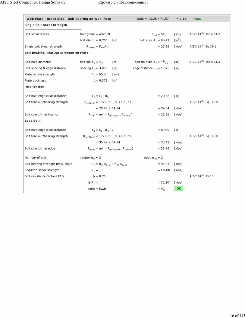
Web Plate - Brace Side - Bolt Bearing on Web Plate ratio = 13.28 / 71.57 = 0.19 PASS
Single Bolt Shear Strength
Bolt shear stress bolt grade = A325-N F = 54.0 [ksi] AISC 14 Table J3.2
bolt dia d = 0.750 [in] bolt area A = 0.442 [in ]
Single bolt shear strength R = F A = 23.86 [kips] AISC 14 Eq J3-1
Bolt Bearing/TearOut Strength on Plate
Bolt hole diameter bolt dia d = ⁄ [in] bolt hole dia d = ⁄ [in] AISC 14 Table J3.3
Bolt spacing & edge distance spacing L = 3.000 [in] edge distance L = 1.375 [in]
Plate tensile strength F = 65.0 [ksi]
Plate thickness t = 0.375 [in]
Interior Bolt
Bolt hole edge clear distance L = L - d = 2.188 [in]
Bolt tear out/bearing strength R = 1.5 L t F ≤ 3.0 d t F AISC 14 Eq J3-6b
= 79.98 ≤ 54.84 = 54.84 [kips]
Bolt strength at interior R = min ( R , R ) = 23.86 [kips]
Edge Bolt
Bolt hole edge clear distance L = L - d / 2 = 0.969 [in]
Bolt tear out/bearing strength R = 1.5 L t F ≤ 3.0 d t F AISC 14 Eq J3-6b
= 35.42 ≤ 54.84 = 35.42 [kips]
Bolt strength at edge R = min ( R , R ) = 23.86 [kips]
Number of bolt interior n = 2 edge n = 2
Bolt bearing strength for all bolts R = n R + n R = 95.43 [kips]
Required shear strength V = = 13.28 [kips]
Bolt resistance factor-LRFD φ = 0.75 AISC 14 J3-10
φ R = = 71.57 [kips]
ratio = 0.19 > V OK
nvth
b b2
n-bolt nv bth
b3
4 h13
16th
s e
u
c s h
n-t&b-in c u b uth
n-in n-t&b-in n-bolt
c e h
n-t&b-ed c u b uth
n-ed n-t&b-ed n-bolt
in ed
n in n-in ed n-ed
u
th
n
u
AISC Steel Connection Design Software http://asp.civilbay.com/connect
16 of 115

Web Plate - Brace Side - Bolt Bearing on Brace Web ratio = 26.55 / 97.42 = 0.27 PASS
Single Bolt Shear Strength
Bolt shear stress bolt grade = A325-N F = 54.0 [ksi] AISC 14 Table J3.2
bolt dia d = 0.750 [in] bolt area A = 0.442 [in ]
Single bolt shear strength R = 2 x F A = 47.71 [kips] AISC 14 Eq J3-1
Bolt Bearing/TearOut Strength on Plate
Bolt hole diameter bolt dia d = ⁄ [in] bolt hole dia d = ⁄ [in] AISC 14 Table J3.3
Bolt spacing & edge distance spacing L = 3.000 [in] edge distance L = 1.625 [in]
Plate tensile strength F = 65.0 [ksi]
Plate thickness t = 0.245 [in]
Interior Bolt
Bolt hole edge clear distance L = L - d = 2.188 [in]
Bolt tear out/bearing strength R = 1.5 L t F ≤ 3.0 d t F AISC 14 Eq J3-6b
= 52.25 ≤ 35.83 = 35.83 [kips]
Bolt strength at interior R = min ( R , R ) = 35.83 [kips]
Edge Bolt
Bolt hole edge clear distance L = L - d / 2 = 1.219 [in]
Bolt tear out/bearing strength R = 1.5 L t F ≤ 3.0 d t F AISC 14 Eq J3-6b
= 29.11 ≤ 35.83 = 29.11 [kips]
Bolt strength at edge R = min ( R , R ) = 29.11 [kips]
Number of bolt interior n = 2 edge n = 2
Bolt bearing strength for all bolts R = n R + n R = 129.89 [kips]
Required shear strength V = = 26.55 [kips]
Bolt resistance factor-LRFD φ = 0.75 AISC 14 J3-10
φ R = = 97.42 [kips]
ratio = 0.27 > V OK
nvth
b b2
n-bolt nv bth
b3
4 h13
16th
s e
u
c s h
n-t&b-in c u b uth
n-in n-t&b-in n-bolt
c e h
n-t&b-ed c u b uth
n-ed n-t&b-ed n-bolt
in ed
n in n-in ed n-ed
u
th
n
u
AISC Steel Connection Design Software http://asp.civilbay.com/connect
17 of 115

Web Plate - Block Shear - Center Strip ratio = 13.28 / 106.03 = 0.13 PASS
Plate Block Shear - Center Strip
Bolt hole diameter bolt dia d = ⁄ [in] bolt hole dia d = ⁄ [in] AISC 14 B4.3b
Plate thickness t = 0.375 [in]
Plate strength F = 50.0 [ksi] F = 65.0 [ksi]
Bolt no in ver & hor dir n = 2 n = 2
Bolt spacing in ver & hor dir s = 3.000 [in] s = 3.000 [in]
Bolt edge dist in ver & hor dir e = 1.375 [in] e = 1.375 [in]
Gross area subject to shear A = [ (n - 1) s + e ] t x 2 = 3.281 [in ]
Net area subject to shear A = A - [(n - 1)+ 0.5] d t x2 = 2.297 [in ]
Net area subject to tension
when sheared out by center strip A = ( n - 1) ( s - d ) t = 0.797 [in ]
Block shear strength required V = = 13.28 [kips]
Uniform tension stress factor U = 1.00 AISC 14 Fig C-J4.2
Bolt shear resistance provided R = min (0.6F A , 0.6F A ) + = 141.38 [kips] AISC 14 Eq J4-5
U F A
Resistance factor-LRFD φ = 0.75 AISC 14 Eq J4-5
φ R = = 106.03 [kips]
ratio = 0.13 > V OK
Web Plate - Block Shear - 1-Side Strip ratio = 13.28 / 89.58 = 0.15 PASS
Plate Block Shear - Side Strip
Bolt hole diameter bolt dia d = ⁄ [in] bolt hole dia d = ⁄ [in] AISC 14 B4.3b
Plate thickness t = 0.375 [in]
Plate strength F = 50.0 [ksi] F = 65.0 [ksi]
Bolt no in ver & hor dir n = 2 n = 2
Bolt spacing in ver & hor dir s = 3.000 [in] s = 3.000 [in]
Bolt edge dist in ver & hor dir e = 1.375 [in] e = 1.375 [in]
Gross area subject to shear A = [ (n - 1) s + e ] t = 1.641 [in ]
Net area subject to shear A = A - [(n - 1)+ 0.5] d t = 1.148 [in ]
Net area subject to tension
when sheared out by side strip A = [(n -1)s +e -((n - 1)+0.5)d ] t = 1.148 [in ]
Block shear strength required V = = 13.28 [kips]
Uniform tension stress factor U = 1.00 AISC 14 Fig C-J4.2
Bolt shear resistance provided R = min (0.6F A , 0.6F A ) + = 119.44 [kips] AISC 14 Eq J4-5
U F A
Resistance factor-LRFD φ = 0.75 AISC 14 Eq J4-5
φ R = = 89.58 [kips]
ratio = 0.15 > V OK
b3
4 h7
8th
p
y u
v h
v h
v h
gv h h h p2
nv gv h h p2
nt v v h p2
u
bsth
n u nv y gvth
bs u ntth
n
u
b3
4 h7
8th
p
y u
v h
v h
v h
gv h h h p2
nv gv h h p2
nt v v v v h p2
u
bsth
n u nv y gvth
bs u ntth
n
u
AISC Steel Connection Design Software http://asp.civilbay.com/connect
18 of 115
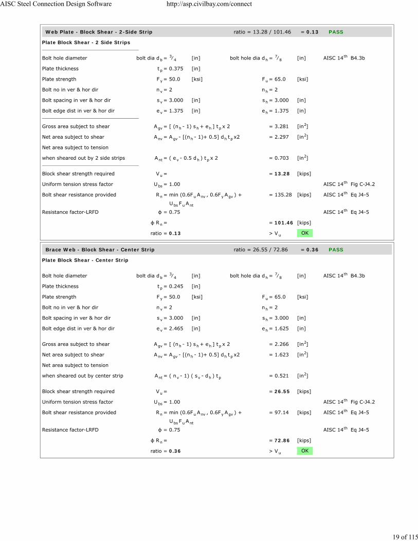
Web Plate - Block Shear - 2-Side Strip ratio = 13.28 / 101.46 = 0.13 PASS
Plate Block Shear - 2 Side Strips
Bolt hole diameter bolt dia d = ⁄ [in] bolt hole dia d = ⁄ [in] AISC 14 B4.3b
Plate thickness t = 0.375 [in]
Plate strength F = 50.0 [ksi] F = 65.0 [ksi]
Bolt no in ver & hor dir n = 2 n = 2
Bolt spacing in ver & hor dir s = 3.000 [in] s = 3.000 [in]
Bolt edge dist in ver & hor dir e = 1.375 [in] e = 1.375 [in]
Gross area subject to shear A = [ (n - 1) s + e ] t x 2 = 3.281 [in ]
Net area subject to shear A = A - [(n - 1)+ 0.5] d t x2 = 2.297 [in ]
Net area subject to tension
when sheared out by 2 side strips A = ( e - 0.5 d ) t x 2 = 0.703 [in ]
Block shear strength required V = = 13.28 [kips]
Uniform tension stress factor U = 1.00 AISC 14 Fig C-J4.2
Bolt shear resistance provided R = min (0.6F A , 0.6F A ) + = 135.28 [kips] AISC 14 Eq J4-5
U F A
Resistance factor-LRFD φ = 0.75 AISC 14 Eq J4-5
φ R = = 101.46 [kips]
ratio = 0.13 > V OK
Brace Web - Block Shear - Center Strip ratio = 26.55 / 72.86 = 0.36 PASS
Plate Block Shear - Center Strip
Bolt hole diameter bolt dia d = ⁄ [in] bolt hole dia d = ⁄ [in] AISC 14 B4.3b
Plate thickness t = 0.245 [in]
Plate strength F = 50.0 [ksi] F = 65.0 [ksi]
Bolt no in ver & hor dir n = 2 n = 2
Bolt spacing in ver & hor dir s = 3.000 [in] s = 3.000 [in]
Bolt edge dist in ver & hor dir e = 2.465 [in] e = 1.625 [in]
Gross area subject to shear A = [ (n - 1) s + e ] t x 2 = 2.266 [in ]
Net area subject to shear A = A - [(n - 1)+ 0.5] d t x2 = 1.623 [in ]
Net area subject to tension
when sheared out by center strip A = ( n - 1) ( s - d ) t = 0.521 [in ]
Block shear strength required V = = 26.55 [kips]
Uniform tension stress factor U = 1.00 AISC 14 Fig C-J4.2
Bolt shear resistance provided R = min (0.6F A , 0.6F A ) + = 97.14 [kips] AISC 14 Eq J4-5
U F A
Resistance factor-LRFD φ = 0.75 AISC 14 Eq J4-5
φ R = = 72.86 [kips]
ratio = 0.36 > V OK
b3
4 h7
8th
p
y u
v h
v h
v h
gv h h h p2
nv gv h h p2
nt v h p2
u
bsth
n u nv y gvth
bs u ntth
n
u
b3
4 h7
8th
p
y u
v h
v h
v h
gv h h h p2
nv gv h h p2
nt v v h p2
u
bsth
n u nv y gvth
bs u ntth
n
u
AISC Steel Connection Design Software http://asp.civilbay.com/connect
19 of 115

Web Plate - Gusset PL Side - Bolt Shear ratio = 26.55 / 143.14 = 0.19 PASS
Bolt shear stress bolt grade = A325-N F = 54.0 [ksi] AISC 14 Table J3.2
bolt dia d = 0.750 [in] bolt area A = 0.442 [in ]
Number of bolt carried shear n = 4.0 shear plane m = 2
Bolt group eccentricity coefficient C = = 1.000
Required shear strength V = = 26.55 [kips]
Bolt shear strength R = F A n m C = 190.85 [kips] AISC 14 Eq J3-1
Bolt resistance factor-LRFD φ = 0.75 AISC 14 Eq J3-1
φ R = = 143.14 [kips]
ratio = 0.19 > V OK
Web Plate - Gusset PL Side - Bolt Bearing on Web Plate ratio = 13.28 / 71.57 = 0.19 PASS
Single Bolt Shear Strength
Bolt shear stress bolt grade = A325-N F = 54.0 [ksi] AISC 14 Table J3.2
bolt dia d = 0.750 [in] bolt area A = 0.442 [in ]
Single bolt shear strength R = F A = 23.86 [kips] AISC 14 Eq J3-1
Bolt Bearing/TearOut Strength on Plate
Bolt hole diameter bolt dia d = ⁄ [in] bolt hole dia d = ⁄ [in] AISC 14 Table J3.3
Bolt spacing & edge distance spacing L = 3.000 [in] edge distance L = 1.375 [in]
Plate tensile strength F = 65.0 [ksi]
Plate thickness t = 0.375 [in]
Interior Bolt
Bolt hole edge clear distance L = L - d = 2.188 [in]
Bolt tear out/bearing strength R = 1.5 L t F ≤ 3.0 d t F AISC 14 Eq J3-6b
= 79.98 ≤ 54.84 = 54.84 [kips]
Bolt strength at interior R = min ( R , R ) = 23.86 [kips]
Edge Bolt
Bolt hole edge clear distance L = L - d / 2 = 0.969 [in]
Bolt tear out/bearing strength R = 1.5 L t F ≤ 3.0 d t F AISC 14 Eq J3-6b
= 35.42 ≤ 54.84 = 35.42 [kips]
Bolt strength at edge R = min ( R , R ) = 23.86 [kips]
Number of bolt interior n = 2 edge n = 2
Bolt bearing strength for all bolts R = n R + n R = 95.43 [kips]
Required shear strength V = = 13.28 [kips]
Bolt resistance factor-LRFD φ = 0.75 AISC 14 J3-10
φ R = = 71.57 [kips]
ratio = 0.19 > V OK
nvth
b b2
s
ec
u
n nv b s ecth
th
n
u
nvth
b b2
n-bolt nv bth
b3
4 h13
16th
s e
u
c s h
n-t&b-in c u b uth
n-in n-t&b-in n-bolt
c e h
n-t&b-ed c u b uth
n-ed n-t&b-ed n-bolt
in ed
n in n-in ed n-ed
u
th
n
u
AISC Steel Connection Design Software http://asp.civilbay.com/connect
20 of 115

Web Plate - Gusset PL Side - Bolt Bearing on Gusset Plate ratio = 26.55 / 138.41 = 0.19 PASS
Single Bolt Shear Strength
Bolt shear stress bolt grade = A325-N F = 54.0 [ksi] AISC 14 Table J3.2
bolt dia d = 0.750 [in] bolt area A = 0.442 [in ]
Single bolt shear strength R = 2 x F A = 47.71 [kips] AISC 14 Eq J3-1
Bolt Bearing/TearOut Strength on Plate
Bolt hole diameter bolt dia d = ⁄ [in] bolt hole dia d = ⁄ [in] AISC 14 Table J3.3
Bolt spacing & edge distance spacing L = 3.000 [in] edge distance L = 1.625 [in]
Plate tensile strength F = 65.0 [ksi]
Plate thickness t = 0.375 [in]
Interior Bolt
Bolt hole edge clear distance L = L - d = 2.188 [in]
Bolt tear out/bearing strength R = 1.5 L t F ≤ 3.0 d t F AISC 14 Eq J3-6b
= 79.98 ≤ 54.84 = 54.84 [kips]
Bolt strength at interior R = min ( R , R ) = 47.71 [kips]
Edge Bolt
Bolt hole edge clear distance L = L - d / 2 = 1.219 [in]
Bolt tear out/bearing strength R = 1.5 L t F ≤ 3.0 d t F AISC 14 Eq J3-6b
= 44.56 ≤ 54.84 = 44.56 [kips]
Bolt strength at edge R = min ( R , R ) = 44.56 [kips]
Number of bolt interior n = 2 edge n = 2
Bolt bearing strength for all bolts R = n R + n R = 184.55 [kips]
Required shear strength V = = 26.55 [kips]
Bolt resistance factor-LRFD φ = 0.75 AISC 14 J3-10
φ R = = 138.41 [kips]
ratio = 0.19 > V OK
nvth
b b2
n-bolt nv bth
b3
4 h13
16th
s e
u
c s h
n-t&b-in c u b uth
n-in n-t&b-in n-bolt
c e h
n-t&b-ed c u b uth
n-ed n-t&b-ed n-bolt
in ed
n in n-in ed n-ed
u
th
n
u
AISC Steel Connection Design Software http://asp.civilbay.com/connect
21 of 115

Gusset Plate at Web Plate - Block Shear - Center Strip ratio = 26.55 / 111.52 = 0.24 PASS
Plate Block Shear - Center Strip
Bolt hole diameter bolt dia d = ⁄ [in] bolt hole dia d = ⁄ [in] AISC 14 B4.3b
Plate thickness t = 0.375 [in]
Plate strength F = 50.0 [ksi] F = 65.0 [ksi]
Bolt no in ver & hor dir n = 2 n = 2
Bolt spacing in ver & hor dir s = 3.000 [in] s = 3.000 [in]
Bolt edge dist in ver & hor dir e = 2.465 [in] e = 1.625 [in]
Gross area subject to shear A = [ (n - 1) s + e ] t x 2 = 3.469 [in ]
Net area subject to shear A = A - [(n - 1)+ 0.5] d t x2 = 2.484 [in ]
Net area subject to tension
when sheared out by center strip A = ( n - 1) ( s - d ) t = 0.797 [in ]
Block shear strength required V = = 26.55 [kips]
Uniform tension stress factor U = 1.00 AISC 14 Fig C-J4.2
Bolt shear resistance provided R = min (0.6F A , 0.6F A ) + = 148.69 [kips] AISC 14 Eq J4-5
U F A
Resistance factor-LRFD φ = 0.75 AISC 14 Eq J4-5
φ R = = 111.52 [kips]
ratio = 0.24 > V OK
Gusset Plate Overall - Block Shear - Center Strip ratio = 100.00 / 242.78 = 0.41 PASS
Plate Block Shear - Center Strip
Bolt hole diameter bolt dia d = ⁄ [in] bolt hole dia d = ⁄ [in] AISC 14 B4.3b
Plate thickness t = 0.375 [in]
Plate strength F = 50.0 [ksi] F = 65.0 [ksi]
Bolt no in ver & hor dir n = 4.0 n = 2
Bolt spacing in hor dir s = 3.000 [in] edge dist e = 1.625 [in]
Width of block shear strip W = 11.930 [in]
Gross area subject to shear A = [ (n - 1) s + e ] t x 2 = 3.469 [in ]
Net area subject to shear A = A - [(n - 1)+ 0.5] d t x2 = 2.484 [in ]
Net area subject to tension
when sheared out by center strip A = [ W - (n - 1) d ] t = 3.489 [in ]
Block shear strength required V = = 100.00 [kips]
Uniform tension stress factor U = 1.00 AISC 14 Fig C-J4.2
Bolt shear resistance provided R = min (0.6F A , 0.6F A ) + = 323.70 [kips] AISC 14 Eq J4-5
U F A
Resistance factor-LRFD φ = 0.75 AISC 14 Eq J4-5
φ R = = 242.78 [kips]
ratio = 0.41 > V OK
b3
4 h7
8th
p
y u
v h
v h
v h
gv h h h p2
nv gv h h p2
nt v v h p2
u
bsth
n u nv y gvth
bs u ntth
n
u
b3
4 h7
8th
p
y u
v h
h h
bs
gv h h h p2
nv gv h h p2
nt bs v h p2
u
bsth
n u nv y gvth
bs u ntth
n
u
AISC Steel Connection Design Software http://asp.civilbay.com/connect
22 of 115

Gusset Plate - Tensile Yield (Whitmore) ratio = 100.00 / 259.77 = 0.38 PASS
Plate Tensile Yielding Check
Plate size width b = 15.394 [in] thickness t = 0.375 [in]
Plate yield strength F = 50.0 [ksi]
Plate gross area in shear A = b t = 5.773 [in ]
Tensile force required P = = 100.00 [kips]
Plate tensile yielding strength R = F A = 288.64 [kips] AISC 14 Eq J4-1
Resistance factor-LRFD φ = 0.90 AISC 14 Eq J4-1
φ R = = 259.77 [kips]
ratio = 0.38 > P OK
Gusset Plate - Tensile Rupture (Whitmore) ratio = 100.00 / 217.44 = 0.46 PASS
Plate Tensile Rupture Check
Bolt hole diameter bolt dia d = ⁄ [in] bolt hole dia d = ⁄ [in] AISC 14 B4.3b
Number of bolt n = 4
Plate size width b = 15.394 [in] thickness t = 0.375 [in]
Plate tensile strength F = 65.0 [ksi]
Plate net area in tension A = ( b - n d ) t = 4.460 [in ]
Tensile force required P = = 100.00 [kips]
Plate tensile rupture strength R = F A = 289.92 [kips] AISC 14 Eq J4-2
Resistance factor-LRFD φ = 0.75 AISC 14 Eq J4-2
φ R = = 217.44 [kips] AISC 14 Eq J4-2
ratio = 0.46 > P OK
Brace Force Load Case 2 Sect=W8X24 P =100.00 kips (C) ratio = 0.51 PASS
Brace Axial Force Distribution
W shape section b = 6.500 [in] t = 0.400 [in]
A = 7.080 [in ]
Brace axial force P = = 100.00 [kips] in compression
Force carried by w shape flange P = P ( b t / A ) = 36.72 [kips]
Force carried by w shape web P = P - 2 P = 26.55 [kips]
Flange Angle - Brace Side - Bolt Shear ratio = 36.72 / 71.57 = 0.51 PASS
Bolt shear stress bolt grade = A325-N F = 54.0 [ksi] AISC 14 Table J3.2
bolt dia d = 0.750 [in] bolt area A = 0.442 [in ]
Number of bolt carried shear n = 4.0 shear plane m = 1
Bolt group eccentricity coefficient C = = 1.000
Required shear strength V = = 36.72 [kips]
Bolt shear strength R = F A n m C = 95.43 [kips] AISC 14 Eq J3-1
Bolt resistance factor-LRFD φ = 0.75 AISC 14 Eq J3-1
φ R = = 71.57 [kips]
ratio = 0.51 > V OK
p p
y
g p p2
u
n y gth
th
n
u
b3
4 h7
8th
p p
u
nt p h p2
u
n u ntth
th
nth
u
f f
2
f f f
w tf
nvth
b b2
s
ec
u
n nv b s ecth
th
n
u
AISC Steel Connection Design Software http://asp.civilbay.com/connect
23 of 115

Flange Angle - Brace Side - Bolt Bearing on Angle ratio = 36.72 / 71.57 = 0.51 PASS
Single Bolt Shear Strength
Bolt shear stress bolt grade = A325-N F = 54.0 [ksi] AISC 14 Table J3.2
bolt dia d = 0.750 [in] bolt area A = 0.442 [in ]
Single bolt shear strength R = F A = 23.86 [kips] AISC 14 Eq J3-1
Bolt Bearing/TearOut Strength on Plate
Bolt hole diameter bolt dia d = ⁄ [in] bolt hole dia d = ⁄ [in] AISC 14 Table J3.3
Bolt spacing spacing L = 3.000 [in]
Plate tensile strength F = 65.0 [ksi]
Plate thickness t = 0.500 [in]
Interior Bolt
Bolt hole edge clear distance L = L - d = 2.188 [in]
Bolt tear out/bearing strength R = 1.5 L t F ≤ 3.0 d t m F AISC 14 Eq J3-6b
= 106.64 ≤ 73.13 = 73.13 [kips]
Bolt strength at interior R = min ( R , R ) = 23.86 [kips]
Number of bolt interior n = 4
Bolt bearing strength for all bolts R = n R = 95.43 [kips]
Required shear strength V = = 36.72 [kips]
Bolt resistance factor-LRFD φ = 0.75 AISC 14 J3-10
φ R = = 71.57 [kips]
ratio = 0.51 > V OK
nvth
b b2
n-bolt nv bth
b3
4 h13
16th
s
u
c s h
n-t&b-in c u b uth
n-in n-t&b-in n-bolt
in
n in n-in
u
th
n
u
AISC Steel Connection Design Software http://asp.civilbay.com/connect
24 of 115

Flange Angle - Brace Side - Bolt Bearing on Brace Flange ratio = 36.72 / 71.57 = 0.51 PASS
Single Bolt Shear Strength
Bolt shear stress bolt grade = A325-N F = 54.0 [ksi] AISC 14 Table J3.2
bolt dia d = 0.750 [in] bolt area A = 0.442 [in ]
Single bolt shear strength R = F A = 23.86 [kips] AISC 14 Eq J3-1
Bolt Bearing/TearOut Strength on Plate
Bolt hole diameter bolt dia d = ⁄ [in] bolt hole dia d = ⁄ [in] AISC 14 Table J3.3
Bolt spacing spacing L = 3.000 [in]
Plate tensile strength F = 65.0 [ksi]
Plate thickness t = 0.400 [in]
Interior Bolt
Bolt hole edge clear distance L = L - d = 2.188 [in]
Bolt tear out/bearing strength R = 1.5 L t F ≤ 3.0 d t m F AISC 14 Eq J3-6b
= 85.31 ≤ 58.50 = 58.50 [kips]
Bolt strength at interior R = min ( R , R ) = 23.86 [kips]
Number of bolt interior n = 4
Bolt bearing strength for all bolts R = n R = 95.43 [kips]
Required shear strength V = = 36.72 [kips]
Bolt resistance factor-LRFD φ = 0.75 AISC 14 J3-10
φ R = = 71.57 [kips]
ratio = 0.51 > V OK
Flange Angle - Gusset PL Side - Bolt Shear ratio = 36.72 / 71.57 = 0.51 PASS
Bolt shear stress bolt grade = A325-N F = 54.0 [ksi] AISC 14 Table J3.2
bolt dia d = 0.750 [in] bolt area A = 0.442 [in ]
Number of bolt carried shear n = 2.0 shear plane m = 2
Bolt group eccentricity coefficient C = = 1.000
Required shear strength V = = 36.72 [kips]
Bolt shear strength R = F A n m C = 95.43 [kips] AISC 14 Eq J3-1
Bolt resistance factor-LRFD φ = 0.75 AISC 14 Eq J3-1
φ R = = 71.57 [kips]
ratio = 0.51 > V OK
nvth
b b2
n-bolt nv bth
b3
4 h13
16th
s
u
c s h
n-t&b-in c u b uth
n-in n-t&b-in n-bolt
in
n in n-in
u
th
n
u
nvth
b b2
s
ec
u
n nv b s ecth
th
n
u
AISC Steel Connection Design Software http://asp.civilbay.com/connect
25 of 115

Flange Angle - Gusset PL Side - Bolt Bearing on Angle ratio = 18.36 / 35.78 = 0.51 PASS
Single Bolt Shear Strength
Bolt shear stress bolt grade = A325-N F = 54.0 [ksi] AISC 14 Table J3.2
bolt dia d = 0.750 [in] bolt area A = 0.442 [in ]
Single bolt shear strength R = F A = 23.86 [kips] AISC 14 Eq J3-1
Bolt Bearing/TearOut Strength on Plate
Bolt hole diameter bolt dia d = ⁄ [in] bolt hole dia d = ⁄ [in] AISC 14 Table J3.3
Bolt spacing spacing L = 3.000 [in]
Plate tensile strength F = 65.0 [ksi]
Plate thickness t = 0.500 [in]
Interior Bolt
Bolt hole edge clear distance L = L - d = 2.188 [in]
Bolt tear out/bearing strength R = 1.5 L t F ≤ 3.0 d t m F AISC 14 Eq J3-6b
= 106.64 ≤ 73.13 = 73.13 [kips]
Bolt strength at interior R = min ( R , R ) = 23.86 [kips]
Number of bolt interior n = 2
Bolt bearing strength for all bolts R = n R = 47.71 [kips]
Required shear strength V = = 18.36 [kips]
Bolt resistance factor-LRFD φ = 0.75 AISC 14 J3-10
φ R = = 35.78 [kips]
ratio = 0.51 > V OK
nvth
b b2
n-bolt nv bth
b3
4 h13
16th
s
u
c s h
n-t&b-in c u b uth
n-in n-t&b-in n-bolt
in
n in n-in
u
th
n
u
AISC Steel Connection Design Software http://asp.civilbay.com/connect
26 of 115

Flange Angle - Gusset PL Side - Bolt Bearing on Gusset Plate ratio = 36.72 / 71.57 = 0.51 PASS
Single Bolt Shear Strength
Bolt shear stress bolt grade = A325-N F = 54.0 [ksi] AISC 14 Table J3.2
bolt dia d = 0.750 [in] bolt area A = 0.442 [in ]
Single bolt shear strength R = 2 x F A = 47.71 [kips] AISC 14 Eq J3-1
Bolt Bearing/TearOut Strength on Plate
Bolt hole diameter bolt dia d = ⁄ [in] bolt hole dia d = ⁄ [in] AISC 14 Table J3.3
Bolt spacing spacing L = 3.000 [in]
Plate tensile strength F = 65.0 [ksi]
Plate thickness t = 0.375 [in]
Interior Bolt
Bolt hole edge clear distance L = L - d = 2.188 [in]
Bolt tear out/bearing strength R = 1.5 L t F ≤ 3.0 d t m F AISC 14 Eq J3-6b
= 79.98 ≤ 54.84 = 54.84 [kips]
Bolt strength at interior R = min ( R , R ) = 47.71 [kips]
Number of bolt interior n = 2
Bolt bearing strength for all bolts R = n R = 95.43 [kips]
Required shear strength V = = 36.72 [kips]
Bolt resistance factor-LRFD φ = 0.75 AISC 14 J3-10
φ R = = 71.57 [kips]
ratio = 0.51 > V OK
Web Plate - Brace Side - Bolt Shear ratio = 26.55 / 143.14 = 0.19 PASS
Bolt shear stress bolt grade = A325-N F = 54.0 [ksi] AISC 14 Table J3.2
bolt dia d = 0.750 [in] bolt area A = 0.442 [in ]
Number of bolt carried shear n = 4.0 shear plane m = 2
Bolt group eccentricity coefficient C = = 1.000
Required shear strength V = = 26.55 [kips]
Bolt shear strength R = F A n m C = 190.85 [kips] AISC 14 Eq J3-1
Bolt resistance factor-LRFD φ = 0.75 AISC 14 Eq J3-1
φ R = = 143.14 [kips]
ratio = 0.19 > V OK
nvth
b b2
n-bolt nv bth
b3
4 h13
16th
s
u
c s h
n-t&b-in c u b uth
n-in n-t&b-in n-bolt
in
n in n-in
u
th
n
u
nvth
b b2
s
ec
u
n nv b s ecth
th
n
u
AISC Steel Connection Design Software http://asp.civilbay.com/connect
27 of 115

Web Plate - Brace Side - Bolt Bearing on Web Plate ratio = 13.28 / 71.57 = 0.19 PASS
Single Bolt Shear Strength
Bolt shear stress bolt grade = A325-N F = 54.0 [ksi] AISC 14 Table J3.2
bolt dia d = 0.750 [in] bolt area A = 0.442 [in ]
Single bolt shear strength R = F A = 23.86 [kips] AISC 14 Eq J3-1
Bolt Bearing/TearOut Strength on Plate
Bolt hole diameter bolt dia d = ⁄ [in] bolt hole dia d = ⁄ [in] AISC 14 Table J3.3
Bolt spacing & edge distance spacing L = 3.000 [in] edge distance L = 1.375 [in]
Plate tensile strength F = 65.0 [ksi]
Plate thickness t = 0.375 [in]
Interior Bolt
Bolt hole edge clear distance L = L - d = 2.188 [in]
Bolt tear out/bearing strength R = 1.5 L t F ≤ 3.0 d t F AISC 14 Eq J3-6b
= 79.98 ≤ 54.84 = 54.84 [kips]
Bolt strength at interior R = min ( R , R ) = 23.86 [kips]
Edge Bolt
Bolt hole edge clear distance L = L - d / 2 = 0.969 [in]
Bolt tear out/bearing strength R = 1.5 L t F ≤ 3.0 d t F AISC 14 Eq J3-6b
= 35.42 ≤ 54.84 = 35.42 [kips]
Bolt strength at edge R = min ( R , R ) = 23.86 [kips]
Number of bolt interior n = 2 edge n = 2
Bolt bearing strength for all bolts R = n R + n R = 95.43 [kips]
Required shear strength V = = 13.28 [kips]
Bolt resistance factor-LRFD φ = 0.75 AISC 14 J3-10
φ R = = 71.57 [kips]
ratio = 0.19 > V OK
nvth
b b2
n-bolt nv bth
b3
4 h13
16th
s e
u
c s h
n-t&b-in c u b uth
n-in n-t&b-in n-bolt
c e h
n-t&b-ed c u b uth
n-ed n-t&b-ed n-bolt
in ed
n in n-in ed n-ed
u
th
n
u
AISC Steel Connection Design Software http://asp.civilbay.com/connect
28 of 115

Web Plate - Brace Side - Bolt Bearing on Brace Web ratio = 26.55 / 107.49 = 0.25 PASS
Single Bolt Shear Strength
Bolt shear stress bolt grade = A325-N F = 54.0 [ksi] AISC 14 Table J3.2
bolt dia d = 0.750 [in] bolt area A = 0.442 [in ]
Single bolt shear strength R = 2 x F A = 47.71 [kips] AISC 14 Eq J3-1
Bolt Bearing/TearOut Strength on Plate
Bolt hole diameter bolt dia d = ⁄ [in] bolt hole dia d = ⁄ [in] AISC 14 Table J3.3
Bolt spacing spacing L = 3.000 [in]
Plate tensile strength F = 65.0 [ksi]
Plate thickness t = 0.245 [in]
Interior Bolt
Bolt hole edge clear distance L = L - d = 2.188 [in]
Bolt tear out/bearing strength R = 1.5 L t F ≤ 3.0 d t m F AISC 14 Eq J3-6b
= 52.25 ≤ 35.83 = 35.83 [kips]
Bolt strength at interior R = min ( R , R ) = 35.83 [kips]
Number of bolt interior n = 4
Bolt bearing strength for all bolts R = n R = 143.33 [kips]
Required shear strength V = = 26.55 [kips]
Bolt resistance factor-LRFD φ = 0.75 AISC 14 J3-10
φ R = = 107.49 [kips]
ratio = 0.25 > V OK
Web Plate - Gusset PL Side - Bolt Shear ratio = 26.55 / 143.14 = 0.19 PASS
Bolt shear stress bolt grade = A325-N F = 54.0 [ksi] AISC 14 Table J3.2
bolt dia d = 0.750 [in] bolt area A = 0.442 [in ]
Number of bolt carried shear n = 4.0 shear plane m = 2
Bolt group eccentricity coefficient C = = 1.000
Required shear strength V = = 26.55 [kips]
Bolt shear strength R = F A n m C = 190.85 [kips] AISC 14 Eq J3-1
Bolt resistance factor-LRFD φ = 0.75 AISC 14 Eq J3-1
φ R = = 143.14 [kips]
ratio = 0.19 > V OK
nvth
b b2
n-bolt nv bth
b3
4 h13
16th
s
u
c s h
n-t&b-in c u b uth
n-in n-t&b-in n-bolt
in
n in n-in
u
th
n
u
nvth
b b2
s
ec
u
n nv b s ecth
th
n
u
AISC Steel Connection Design Software http://asp.civilbay.com/connect
29 of 115

Web Plate - Gusset PL Side - Bolt Bearing on Web Plate ratio = 13.28 / 71.57 = 0.19 PASS
Single Bolt Shear Strength
Bolt shear stress bolt grade = A325-N F = 54.0 [ksi] AISC 14 Table J3.2
bolt dia d = 0.750 [in] bolt area A = 0.442 [in ]
Single bolt shear strength R = F A = 23.86 [kips] AISC 14 Eq J3-1
Bolt Bearing/TearOut Strength on Plate
Bolt hole diameter bolt dia d = ⁄ [in] bolt hole dia d = ⁄ [in] AISC 14 Table J3.3
Bolt spacing spacing L = 3.000 [in]
Plate tensile strength F = 65.0 [ksi]
Plate thickness t = 0.375 [in]
Interior Bolt
Bolt hole edge clear distance L = L - d = 2.188 [in]
Bolt tear out/bearing strength R = 1.5 L t F ≤ 3.0 d t m F AISC 14 Eq J3-6b
= 79.98 ≤ 54.84 = 54.84 [kips]
Bolt strength at interior R = min ( R , R ) = 23.86 [kips]
Number of bolt interior n = 4
Bolt bearing strength for all bolts R = n R = 95.43 [kips]
Required shear strength V = = 13.28 [kips]
Bolt resistance factor-LRFD φ = 0.75 AISC 14 J3-10
φ R = = 71.57 [kips]
ratio = 0.19 > V OK
nvth
b b2
n-bolt nv bth
b3
4 h13
16th
s
u
c s h
n-t&b-in c u b uth
n-in n-t&b-in n-bolt
in
n in n-in
u
th
n
u
AISC Steel Connection Design Software http://asp.civilbay.com/connect
30 of 115
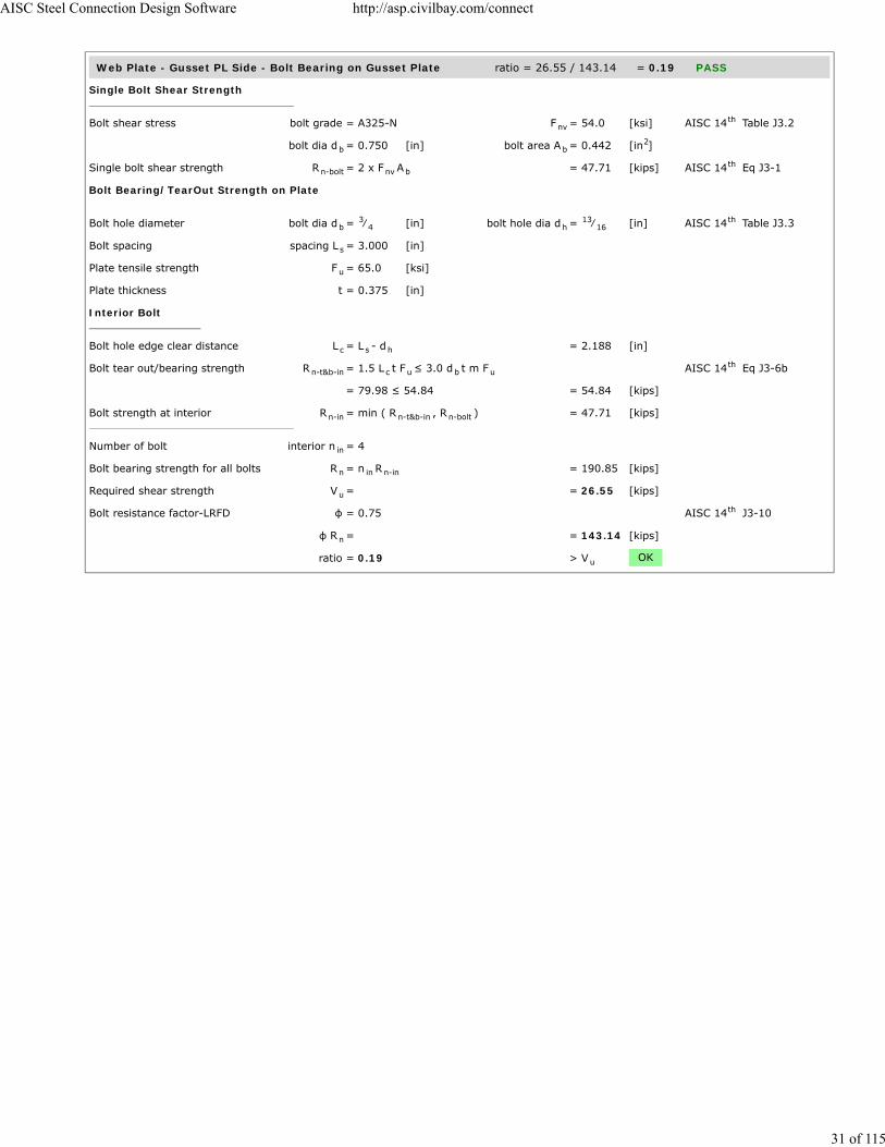
Web Plate - Gusset PL Side - Bolt Bearing on Gusset Plate ratio = 26.55 / 143.14 = 0.19 PASS
Single Bolt Shear Strength
Bolt shear stress bolt grade = A325-N F = 54.0 [ksi] AISC 14 Table J3.2
bolt dia d = 0.750 [in] bolt area A = 0.442 [in ]
Single bolt shear strength R = 2 x F A = 47.71 [kips] AISC 14 Eq J3-1
Bolt Bearing/TearOut Strength on Plate
Bolt hole diameter bolt dia d = ⁄ [in] bolt hole dia d = ⁄ [in] AISC 14 Table J3.3
Bolt spacing spacing L = 3.000 [in]
Plate tensile strength F = 65.0 [ksi]
Plate thickness t = 0.375 [in]
Interior Bolt
Bolt hole edge clear distance L = L - d = 2.188 [in]
Bolt tear out/bearing strength R = 1.5 L t F ≤ 3.0 d t m F AISC 14 Eq J3-6b
= 79.98 ≤ 54.84 = 54.84 [kips]
Bolt strength at interior R = min ( R , R ) = 47.71 [kips]
Number of bolt interior n = 4
Bolt bearing strength for all bolts R = n R = 190.85 [kips]
Required shear strength V = = 26.55 [kips]
Bolt resistance factor-LRFD φ = 0.75 AISC 14 J3-10
φ R = = 143.14 [kips]
ratio = 0.19 > V OK
nvth
b b2
n-bolt nv bth
b3
4 h13
16th
s
u
c s h
n-t&b-in c u b uth
n-in n-t&b-in n-bolt
in
n in n-in
u
th
n
u
AISC Steel Connection Design Software http://asp.civilbay.com/connect
31 of 115

Web Plate - Compression Buckling ratio = 13.28 / 73.02 = 0.18 PASS
Plate Compression Check
Plate size width b = 5.750 [in] thickness t = 0.375 [in]
F = 50.0 [ksi] E = 29000 [ksi]
Plate gross area in compression A = b t = 2.156 [in ]
Plate radius of gyration r = t / 12 = 0.108 [in]
Plate effective length factor K = = 1.00
Plate unbraced length L = = 6.750 [in]
Plate slenderness KL/r = 1.00 x L / r = 62.35
when KL
r > 25 , use Chapter E AISC 14 J4.4 (b)
Elastic buckling stress F = π E
( KL/r ) = 73.62 [ksi] AISC 14 Eq E3-4
when KL
r ≤ 4.71 (
E
F ) = 113.43 AISC 14 E3 (a)
Critical stress F = 0.658 F = 37.63 [ksi] AISC 14 Eq E3-2
Plate compression required P = = 13.28 [kips]
Plate compression provided R = F x A = 81.13 [kips] AISC 14 Eq E3-1
Bolt resistance factor-LRFD φ = 0.90 AISC 14 E1
φ R = = 73.02 [kips]
ratio = 0.18 > P OK
p p
y
g p p2
p √
u
u
th
e
2
2th
y
0.5 th
cr( F / F )y e
yth
u
n cr gth
th
n
u
AISC Steel Connection Design Software http://asp.civilbay.com/connect
32 of 115

Gusset Plate - Compression (Whitmore) ratio = 100.00 / 220.48 = 0.45 PASS
Plate Compression Check
Plate size width b = 15.394 [in] thickness t = 0.375 [in]
F = 50.0 [ksi] E = 29000 [ksi]
Plate gross area in compression A = b t = 5.773 [in ]
Plate radius of gyration r = t / 12 = 0.108 [in]
Plate effective length factor K = = 0.50
Plate unbraced length L = = 10.254 [in]
Plate slenderness KL/r = 0.50 x L / r = 47.36
when KL
r > 25 , use Chapter E AISC 14 J4.4 (b)
Elastic buckling stress F = π E
( KL/r ) = 127.60 [ksi] AISC 14 Eq E3-4
when KL
r ≤ 4.71 (
E
F ) = 113.43 AISC 14 E3 (a)
Critical stress F = 0.658 F = 42.44 [ksi] AISC 14 Eq E3-2
Plate compression required P = = 100.00 [kips]
Plate compression provided R = F x A = 244.98 [kips] AISC 14 Eq E3-1
Bolt resistance factor-LRFD φ = 0.90 AISC 14 E1
φ R = = 220.48 [kips]
ratio = 0.45 > P OK
p p
y
g p p2
p √
u
u
th
e
2
2th
y
0.5 th
cr( F / F )y e
yth
u
n cr gth
th
n
u
AISC Steel Connection Design Software http://asp.civilbay.com/connect
33 of 115

Top Brace - Gusset to Column End Plate Connection Code=AISC 360-10 LRFD
Result Summary geometries & weld limitations = PASS limit states max ratio = 0.42 PASS
Geometry Restriction Checks - End Plate to Column Web PASS
Min Bolt Edge Distance - End Plate to Column Web
Bolt diameter d = = 0.750 [in]
Min edge distance allowed L = = 1.000 [in] AISC 14 Table J3.4
Min edge distance in End Plate toColumn Web
L = = 1.375 [in]
> L OK
Min Bolt Spacing - End Plate to Column Web
Bolt diameter d = = 0.750 [in]
Min bolt spacing allowed L = 2.667 d = 2.000 [in] AISC 14 J3.3
Min Bolt spacing in End Plate toColumn Web
L = = 3.000 [in]
> L OK
Weld Limitation Checks - Gusset Plate to End Plate PASS
Min Fillet Weld Size
Thinner part joined thickness t = = 0.375 [in]
Min fillet weld size allowed w = = 0.188 [in] AISC 14 Table J2.4
Fillet weld size provided w = = 0.313 [in]
> w OK
Min Fillet Weld Length
Fillet weld size provided w = = 0.313 [in]
Min fillet weld length allowed L = 4 x w = 1.250 [in] AISC 14 J2.2b
Min fillet weld length L = = 6.625 [in]
> L OK
Brace Force Load Case 1 Gusset plate t=0.375 P =-100.00 kips (T) ratio = 0.42 PASS
Gusset Plate - Shear Yielding ratio = 30.16 / 74.53 = 0.40 PASS
Plate Shear Yielding Check
Plate size width b = 6.625 [in] thickness t = 0.375 [in]
Plate yield strength F = 50.0 [ksi]
Plate gross area in shear A = b t = 2.484 [in ]
Shear force required V = = 30.16 [kips]
Plate shear yielding strength R = 0.6 F A = 74.53 [kips] AISC 14 Eq J4-3
Resistance factor-LRFD φ = 1.00 AISC 14 Eq J4-3
φ R = = 74.53 [kips]
ratio = 0.40 > V OK
b
e-minth
e
e-min
b
s-min bth
s
s-min
minth
min
minth
min
p p
y
gv p p2
u
n y gvth
th
n
u
AISC Steel Connection Design Software http://asp.civilbay.com/connect
34 of 115

Gusset Plate - Shear Rupture ratio = 30.16 / 72.67 = 0.42 PASS
Plate Shear Rupture Check
Plate size width b = 6.625 [in] thickness t = 0.375 [in]
Plate tensile strength F = 65.0 [ksi]
Plate net area in shear A = b t = 2.484 [in ]
Shear force in demand V = = 30.16 [kips]
Plate shear rupture strength R = 0.6 F A = 96.89 [kips] AISC 14 Eq J4-4
Resistance factor-LRFD φ = 0.75 AISC 14 Eq J4-4
φ R = = 72.67 [kips]
ratio = 0.42 > V OK
End Plate - Shear Yield ratio = 15.08 / 64.69 = 0.23 PASS
Plate Shear Yielding Check
Plate size width b = 5.750 [in] thickness t = 0.375 [in]
Plate yield strength F = 50.0 [ksi]
Plate gross area in shear A = b t = 2.156 [in ]
Shear force required V = = 15.08 [kips]
Plate shear yielding strength R = 0.6 F A = 64.69 [kips] AISC 14 Eq J4-3
Resistance factor-LRFD φ = 1.00 AISC 14 Eq J4-3
φ R = = 64.69 [kips]
ratio = 0.23 > V OK
End Plate - Shear Rupture ratio = 15.08 / 43.88 = 0.34 PASS
Plate Shear Rupture Check
Bolt hole diameter bolt dia d = ⁄ [in] bolt hole dia d = ⁄ [in] AISC 14 B4.3b
Number of bolt n = 2
Plate size width b = 5.750 [in] thickness t = 0.375 [in]
Plate tensile strength F = 65.0 [ksi]
Plate net area in shear A = ( b - n d ) t = 1.500 [in ]
Shear force required V = = 15.08 [kips]
Plate shear rupture strength R = 0.6 F A = 58.50 [kips] AISC 14 Eq J4-4
Resistance factor-LRFD φ = 0.75 AISC 14 Eq J4-4
φ R = = 43.88 [kips]
ratio = 0.34 > V OK
p p
u
nv p p2
u
n u nvth
th
n
u
p p
y
gv p p2
u
n y gvth
th
n
u
b3
4 h7
8th
p p
u
nv p h p2
u
n u nvth
th
n
u
AISC Steel Connection Design Software http://asp.civilbay.com/connect
35 of 115

End Plate - Block Shear - Center Strip ratio = 30.16 / 124.31 = 0.24 PASS
Plate Block Shear - Center Strip
Bolt hole diameter bolt dia d = ⁄ [in] bolt hole dia d = ⁄ [in] AISC 14 B4.3b
Plate thickness t = 0.375 [in]
Plate strength F = 50.0 [ksi] F = 65.0 [ksi]
Bolt no in ver & hor dir n = 2 n = 2
Bolt spacing in ver & hor dir s = 4.000 [in] s = 3.000 [in]
Bolt edge dist in ver & hor dir e = 1.375 [in] e = 1.375 [in]
Gross area subject to shear A = [ (n - 1) s + e ] t x 2 = 3.281 [in ]
Net area subject to shear A = A - [(n - 1)+ 0.5] d t x2 = 2.297 [in ]
Net area subject to tension
when sheared out by center strip A = ( n - 1) ( s - d ) t = 1.172 [in ]
Block shear strength required V = = 30.16 [kips]
Uniform tension stress factor U = 1.00 AISC 14 Fig C-J4.2
Bolt shear resistance provided R = min (0.6F A , 0.6F A ) + = 165.75 [kips] AISC 14 Eq J4-5
U F A
Resistance factor-LRFD φ = 0.75 AISC 14 Eq J4-5
φ R = = 124.31 [kips]
ratio = 0.24 > V OK
End Plate - Block Shear - 2-Side Strip ratio = 30.16 / 101.46 = 0.30 PASS
Plate Block Shear - 2 Side Strips
Bolt hole diameter bolt dia d = ⁄ [in] bolt hole dia d = ⁄ [in] AISC 14 B4.3b
Plate thickness t = 0.375 [in]
Plate strength F = 50.0 [ksi] F = 65.0 [ksi]
Bolt no in ver & hor dir n = 2 n = 2
Bolt spacing in ver & hor dir s = 4.000 [in] s = 3.000 [in]
Bolt edge dist in ver & hor dir e = 1.375 [in] e = 1.375 [in]
Gross area subject to shear A = [ (n - 1) s + e ] t x 2 = 3.281 [in ]
Net area subject to shear A = A - [(n - 1)+ 0.5] d t x2 = 2.297 [in ]
Net area subject to tension
when sheared out by 2 side strips A = ( e - 0.5 d ) t x 2 = 0.703 [in ]
Block shear strength required V = = 30.16 [kips]
Uniform tension stress factor U = 1.00 AISC 14 Fig C-J4.2
Bolt shear resistance provided R = min (0.6F A , 0.6F A ) + = 135.28 [kips] AISC 14 Eq J4-5
U F A
Resistance factor-LRFD φ = 0.75 AISC 14 Eq J4-5
φ R = = 101.46 [kips]
ratio = 0.30 > V OK
b3
4 h7
8th
p
y u
v h
v h
v h
gv h h h p2
nv gv h h p2
nt v v h p2
u
bsth
n u nv y gvth
bs u ntth
n
u
b3
4 h7
8th
p
y u
v h
v h
v h
gv h h h p2
nv gv h h p2
nt v h p2
u
bsth
n u nv y gvth
bs u ntth
n
u
AISC Steel Connection Design Software http://asp.civilbay.com/connect
36 of 115

End Plate - Bolt Bearing on End Plate ratio = 30.16 / 71.57 = 0.42 PASS
Single Bolt Shear Strength
Bolt shear stress bolt grade = A325-N F = 54.0 [ksi] AISC 14 Table J3.2
bolt dia d = 0.750 [in] bolt area A = 0.442 [in ]
Single bolt shear strength R = F A = 23.86 [kips] AISC 14 Eq J3-1
Bolt Bearing/TearOut Strength on Plate
Bolt hole diameter bolt dia d = ⁄ [in] bolt hole dia d = ⁄ [in] AISC 14 Table J3.3
Bolt spacing & edge distance spacing L = 3.000 [in] edge distance L = 1.375 [in]
Plate tensile strength F = 65.0 [ksi]
Plate thickness t = 0.375 [in]
Interior Bolt
Bolt hole edge clear distance L = L - d = 2.188 [in]
Bolt tear out/bearing strength R = 1.5 L t F ≤ 3.0 d t F AISC 14 Eq J3-6b
= 79.98 ≤ 54.84 = 54.84 [kips]
Bolt strength at interior R = min ( R , R ) = 23.86 [kips]
Edge Bolt
Bolt hole edge clear distance L = L - d / 2 = 0.969 [in]
Bolt tear out/bearing strength R = 1.5 L t F ≤ 3.0 d t F AISC 14 Eq J3-6b
= 35.42 ≤ 54.84 = 35.42 [kips]
Bolt strength at edge R = min ( R , R ) = 23.86 [kips]
Number of bolt interior n = 2 edge n = 2
Bolt bearing strength for all bolts R = n R + n R = 95.43 [kips]
Required shear strength V = = 30.16 [kips]
Bolt resistance factor-LRFD φ = 0.75 AISC 14 J3-10
φ R = = 71.57 [kips]
ratio = 0.42 > V OK
End Plate / Column - Bolt Shear ratio = 30.16 / 71.57 = 0.42 PASS
Bolt group forces shear V = 30.16 [kips] axial P = 0.99 [kips]
Bolt shear stress grade = A325-N F = 54.0 [ksi] AISC 14 Table J3.2
bolt dia d = 0.750 [in] bolt area A = 0.442 [in ]
Number of bolt carried shear n = 4.0 shear plane m = 1
Bolt group eccentricity coefficient C = = 1.000
Required shear strength V = = 30.16 [kips]
Bolt shear strength R = F A n m C = 95.43 [kips] AISC 14 Eq J3-1
Bolt resistance factor-LRFD φ = 0.75 AISC 14 Eq J3-1
φ R = = 71.57 [kips]
ratio = 0.42 > V OK
nvth
b b2
n-bolt nv bth
b3
4 h13
16th
s e
u
c s h
n-t&b-in c u b uth
n-in n-t&b-in n-bolt
c e h
n-t&b-ed c u b uth
n-ed n-t&b-ed n-bolt
in ed
n in n-in ed n-ed
u
th
n
u
nvth
b b2
s
ec
u
n nv b s ecth
th
n
u
AISC Steel Connection Design Software http://asp.civilbay.com/connect
37 of 115

End Plate / Column - Bolt Bearing on Column ratio = 30.16 / 71.57 = 0.42 PASS
Single Bolt Shear Strength
Bolt shear stress bolt grade = A325-N F = 54.0 [ksi] AISC 14 Table J3.2
bolt dia d = 0.750 [in] bolt area A = 0.442 [in ]
Single bolt shear strength R = F A = 23.86 [kips] AISC 14 Eq J3-1
Bolt Bearing/TearOut Strength on Plate
Bolt hole diameter bolt dia d = ⁄ [in] bolt hole dia d = ⁄ [in] AISC 14 Table J3.3
Bolt spacing spacing L = 3.000 [in]
Plate tensile strength F = 65.0 [ksi]
Plate thickness t = 0.295 [in]
Interior Bolt
Bolt hole edge clear distance L = L - d = 2.188 [in]
Bolt tear out/bearing strength R = 1.5 L t F ≤ 3.0 d t m F AISC 14 Eq J3-6b
= 62.92 ≤ 43.14 = 43.14 [kips]
Bolt strength at interior R = min ( R , R ) = 23.86 [kips]
Number of bolt interior n = 4
Bolt bearing strength for all bolts R = n R = 95.43 [kips]
Required shear strength V = = 30.16 [kips]
Bolt resistance factor-LRFD φ = 0.75 AISC 14 J3-10
φ R = = 71.57 [kips]
ratio = 0.42 > V OK
nvth
b b2
n-bolt nv bth
b3
4 h13
16th
s
u
c s h
n-t&b-in c u b uth
n-in n-t&b-in n-bolt
in
n in n-in
u
th
n
u
AISC Steel Connection Design Software http://asp.civilbay.com/connect
38 of 115

Bolt Tensile Prying Action on End Plate ratio = 0.25 / 7.06 = 0.04 PASS
Bolt group forces shear V = 30.16 [kips] axial P = -0.99 [kips]
Single Bolt Tensile Capacity Without Considering Prying
Bolt grade grade = A325-N
Nominal tensile/shear stress F = 90.0 [ksi] F = 54.0 [ksi] AISC 14 Table J3.2
bolt dia d = 0.750 [in] bolt area A = 0.442 [in ]
Bolt group shear force shear V = 30.16 [kips] no of bolt n = 4
Shear stress required f = V / ( n A ) = 17.07 [ksi]
Resistance factor-LRFD φ = 0.75 AISC 14 J3.7
Modified nominal tensile stress F' = 1.3 F - Fφ F
f ≤ F = 79.07 [ksi] AISC 14 Eq J3-3a
Bolt norminal tensile strength r = F' A = 34.93 [kips] AISC 14 Eq J3-1
Resistance factor-LRFD φ = 0.75 AISC 14 J3.6
Single bolt tensile capacity φ r = = 26.20 [kips]
Single Bolt Tensile Capacity After Considering Prying
End plate width w = 6.750 [in] bolt gage g = 4.000 [in]
web t = 0.375 [in]
Dist from bolt center to plate edge a = 0.5 (w - g) = 1.375 [in]
a' = a + 0.5 d ≤ (1.25 b + 0.5 d ) = 1.750 [in] AISC 14 Eq 9-27
Bolt hole diameter bolt dia d = 0.750 [in] bolt hole dia d = 0.813 [in] AISC 14 B4.3b
Dist from bolt center to face of web b = 0.5(g - t ) = 1.813 [in]
b' = b - 0.5 d = 1.438 [in] AISC 14 Eq 9-21
Bolt pitch spacing s = 3.000
Bolt tributary length p = s p ≤ 2b and p ≤ s = 2.875 [in] AISC 14 Page 9-11
ρ = b' / a' = 0.821 AISC 14 Eq 9-26
δ = 1 - d / p = 0.717 AISC 14 Eq 9-24
Tensile capacity per bolt beforeconsidering prying
B = from calc shown in above section = 26.20 [kips]
Resistance factor-LRFD φ = 0.90 AISC 14 Page 9-10
End plate thickness t = 0.375 [in] tensile F = 65.0 [ksi]
Plate thickness req'd to develop bolttensile capacity without prying
t = ( 4 B b'φ p F
) = 0.946 [in] AISC 14 Eq 9-30a
α' = 1δ (1 + ρ )
[ ( tt
) - 1 ] = 4.109 AISC 14 Eq 9-35
when α' > 1 Q = ( tt
) (1 + δ ) = 0.270 AISC 14 Eq 9-34
Bolt tensile force per bolt in demand T = from calc shown below = 0.25 [kips]
Tensile strength per bolt afterconsidering prying
φ r = B x Q = 7.06 [kips] AISC 14 Eq 9-31
ratio = 0.04 > T OK
Calculate Max Single Bolt Tensile Load
Bolt group force axial P = 0.99 [kips]
Bolt number Bolt Row n = 2 Bolt Col n = 2
Bolt tensile force per bolt T = P / ( n n ) = 0.25 [kips]
nt nvth
b b2
rv b
th
nt ntnt
nvrv nt
th
n nt bth
th
n
w
b bth
b hth
w
bth
v
v vth
th
hth
th
u
cu
0.5 th
c 2 th
c
2 th
nth
h v
v h
AISC Steel Connection Design Software http://asp.civilbay.com/connect
39 of 115

Gusset Plate to End Plate Weld Strength ratio = 4.55 / 10.97 = 0.42 PASS
Weld Group Forces
shear V = 30.16 [kips] axial P = -0.99 [kips] in tension
Gusset-end plate fillet weld length L = weld length tributary to bolt group = 6.625 [in]
Combined Weld Stress
Weld stress from axial force f = P / L = -0.149 [kip/in] in tension
Weld stress from shear force f = V / L = 4.552 [kip/in]
Weld stress combined - max f = ( f + f ) = 4.555 [kip/in] AISC 14 Eq 8-11
Weld stress load angle θ = tan ( f
f ) = 1.9 [°]
Fillet Weld Strength Calc
Fillet weld leg size w = ⁄ [in] load angle θ = 1.9 [°]
Electrode strength F = 70.0 [ksi] strength coeff C = 1.00 AISC 14 Table 8-3
Number of weld line n = 2 for double fillet
Load angle coefficient C = ( 1 + 0.5 sin θ ) = 1.00 AISC 14 Page 8-9
Fillet weld shear strength R = 0.6 (C x 70 ksi) 0.707 w n C = 18.614 [kip/in] AISC 14 Eq 8-1
Base metal - gusset plate thickness t = 0.375 [in] tensile F = 65.0 [ksi]
Base metal - gusset plate is in shear, shear rupture as per AISC 14 Eq J4-4 is checked AISC 14 J2.4
Base metal shear rupture R = 0.6 F t = 14.625 [kip/in] AISC 14 Eq J4-4
Double fillet linear shear strength R = min ( R , R ) = 14.625 [kip/in] AISC 14 Eq 9-2
Resistance factor-LRFD φ = 0.75 AISC 14 Eq 8-1
φ R = = 10.969 [kip/in]
ratio = 0.42 > f OK
Brace Force Load Case 2 Gusset plate t=0.375 P =100.00 kips (C) ratio = 0.42 PASS
Gusset Plate - Shear Yielding ratio = 30.16 / 74.53 = 0.40 PASS
Plate Shear Yielding Check
Plate size width b = 6.625 [in] thickness t = 0.375 [in]
Plate yield strength F = 50.0 [ksi]
Plate gross area in shear A = b t = 2.484 [in ]
Shear force required V = = 30.16 [kips]
Plate shear yielding strength R = 0.6 F A = 74.53 [kips] AISC 14 Eq J4-3
Resistance factor-LRFD φ = 1.00 AISC 14 Eq J4-3
φ R = = 74.53 [kips]
ratio = 0.40 > V OK
a
v
max2a
2v
0.5 th
-1 a
v
516
EXX 1th
21.5 th
n-w 1 2th
u
th th
n-b uth
n n-w n-bth
th
n
max
p p
y
gv p p2
u
n y gvth
th
n
u
AISC Steel Connection Design Software http://asp.civilbay.com/connect
40 of 115

Gusset Plate - Shear Rupture ratio = 30.16 / 72.67 = 0.42 PASS
Plate Shear Rupture Check
Plate size width b = 6.625 [in] thickness t = 0.375 [in]
Plate tensile strength F = 65.0 [ksi]
Plate net area in shear A = b t = 2.484 [in ]
Shear force in demand V = = 30.16 [kips]
Plate shear rupture strength R = 0.6 F A = 96.89 [kips] AISC 14 Eq J4-4
Resistance factor-LRFD φ = 0.75 AISC 14 Eq J4-4
φ R = = 72.67 [kips]
ratio = 0.42 > V OK
End Plate - Shear Yield ratio = 15.08 / 64.69 = 0.23 PASS
Plate Shear Yielding Check
Plate size width b = 5.750 [in] thickness t = 0.375 [in]
Plate yield strength F = 50.0 [ksi]
Plate gross area in shear A = b t = 2.156 [in ]
Shear force required V = = 15.08 [kips]
Plate shear yielding strength R = 0.6 F A = 64.69 [kips] AISC 14 Eq J4-3
Resistance factor-LRFD φ = 1.00 AISC 14 Eq J4-3
φ R = = 64.69 [kips]
ratio = 0.23 > V OK
End Plate - Shear Rupture ratio = 15.08 / 43.88 = 0.34 PASS
Plate Shear Rupture Check
Bolt hole diameter bolt dia d = ⁄ [in] bolt hole dia d = ⁄ [in] AISC 14 B4.3b
Number of bolt n = 2
Plate size width b = 5.750 [in] thickness t = 0.375 [in]
Plate tensile strength F = 65.0 [ksi]
Plate net area in shear A = ( b - n d ) t = 1.500 [in ]
Shear force required V = = 15.08 [kips]
Plate shear rupture strength R = 0.6 F A = 58.50 [kips] AISC 14 Eq J4-4
Resistance factor-LRFD φ = 0.75 AISC 14 Eq J4-4
φ R = = 43.88 [kips]
ratio = 0.34 > V OK
p p
u
nv p p2
u
n u nvth
th
n
u
p p
y
gv p p2
u
n y gvth
th
n
u
b3
4 h7
8th
p p
u
nv p h p2
u
n u nvth
th
n
u
AISC Steel Connection Design Software http://asp.civilbay.com/connect
41 of 115

End Plate - Block Shear - Center Strip ratio = 30.16 / 124.31 = 0.24 PASS
Plate Block Shear - Center Strip
Bolt hole diameter bolt dia d = ⁄ [in] bolt hole dia d = ⁄ [in] AISC 14 B4.3b
Plate thickness t = 0.375 [in]
Plate strength F = 50.0 [ksi] F = 65.0 [ksi]
Bolt no in ver & hor dir n = 2 n = 2
Bolt spacing in ver & hor dir s = 4.000 [in] s = 3.000 [in]
Bolt edge dist in ver & hor dir e = 1.375 [in] e = 1.375 [in]
Gross area subject to shear A = [ (n - 1) s + e ] t x 2 = 3.281 [in ]
Net area subject to shear A = A - [(n - 1)+ 0.5] d t x2 = 2.297 [in ]
Net area subject to tension
when sheared out by center strip A = ( n - 1) ( s - d ) t = 1.172 [in ]
Block shear strength required V = = 30.16 [kips]
Uniform tension stress factor U = 1.00 AISC 14 Fig C-J4.2
Bolt shear resistance provided R = min (0.6F A , 0.6F A ) + = 165.75 [kips] AISC 14 Eq J4-5
U F A
Resistance factor-LRFD φ = 0.75 AISC 14 Eq J4-5
φ R = = 124.31 [kips]
ratio = 0.24 > V OK
End Plate - Block Shear - 2-Side Strip ratio = 30.16 / 101.46 = 0.30 PASS
Plate Block Shear - 2 Side Strips
Bolt hole diameter bolt dia d = ⁄ [in] bolt hole dia d = ⁄ [in] AISC 14 B4.3b
Plate thickness t = 0.375 [in]
Plate strength F = 50.0 [ksi] F = 65.0 [ksi]
Bolt no in ver & hor dir n = 2 n = 2
Bolt spacing in ver & hor dir s = 4.000 [in] s = 3.000 [in]
Bolt edge dist in ver & hor dir e = 1.375 [in] e = 1.375 [in]
Gross area subject to shear A = [ (n - 1) s + e ] t x 2 = 3.281 [in ]
Net area subject to shear A = A - [(n - 1)+ 0.5] d t x2 = 2.297 [in ]
Net area subject to tension
when sheared out by 2 side strips A = ( e - 0.5 d ) t x 2 = 0.703 [in ]
Block shear strength required V = = 30.16 [kips]
Uniform tension stress factor U = 1.00 AISC 14 Fig C-J4.2
Bolt shear resistance provided R = min (0.6F A , 0.6F A ) + = 135.28 [kips] AISC 14 Eq J4-5
U F A
Resistance factor-LRFD φ = 0.75 AISC 14 Eq J4-5
φ R = = 101.46 [kips]
ratio = 0.30 > V OK
b3
4 h7
8th
p
y u
v h
v h
v h
gv h h h p2
nv gv h h p2
nt v v h p2
u
bsth
n u nv y gvth
bs u ntth
n
u
b3
4 h7
8th
p
y u
v h
v h
v h
gv h h h p2
nv gv h h p2
nt v h p2
u
bsth
n u nv y gvth
bs u ntth
n
u
AISC Steel Connection Design Software http://asp.civilbay.com/connect
42 of 115

End Plate - Bolt Bearing on End Plate ratio = 30.16 / 71.57 = 0.42 PASS
Single Bolt Shear Strength
Bolt shear stress bolt grade = A325-N F = 54.0 [ksi] AISC 14 Table J3.2
bolt dia d = 0.750 [in] bolt area A = 0.442 [in ]
Single bolt shear strength R = F A = 23.86 [kips] AISC 14 Eq J3-1
Bolt Bearing/TearOut Strength on Plate
Bolt hole diameter bolt dia d = ⁄ [in] bolt hole dia d = ⁄ [in] AISC 14 Table J3.3
Bolt spacing & edge distance spacing L = 3.000 [in] edge distance L = 1.375 [in]
Plate tensile strength F = 65.0 [ksi]
Plate thickness t = 0.375 [in]
Interior Bolt
Bolt hole edge clear distance L = L - d = 2.188 [in]
Bolt tear out/bearing strength R = 1.5 L t F ≤ 3.0 d t F AISC 14 Eq J3-6b
= 79.98 ≤ 54.84 = 54.84 [kips]
Bolt strength at interior R = min ( R , R ) = 23.86 [kips]
Edge Bolt
Bolt hole edge clear distance L = L - d / 2 = 0.969 [in]
Bolt tear out/bearing strength R = 1.5 L t F ≤ 3.0 d t F AISC 14 Eq J3-6b
= 35.42 ≤ 54.84 = 35.42 [kips]
Bolt strength at edge R = min ( R , R ) = 23.86 [kips]
Number of bolt interior n = 2 edge n = 2
Bolt bearing strength for all bolts R = n R + n R = 95.43 [kips]
Required shear strength V = = 30.16 [kips]
Bolt resistance factor-LRFD φ = 0.75 AISC 14 J3-10
φ R = = 71.57 [kips]
ratio = 0.42 > V OK
End Plate / Column - Bolt Shear ratio = 30.16 / 71.57 = 0.42 PASS
Bolt shear stress bolt grade = A325-N F = 54.0 [ksi] AISC 14 Table J3.2
bolt dia d = 0.750 [in] bolt area A = 0.442 [in ]
Number of bolt carried shear n = 4.0 shear plane m = 1
Bolt group eccentricity coefficient C = = 1.000
Required shear strength V = = 30.16 [kips]
Bolt shear strength R = F A n m C = 95.43 [kips] AISC 14 Eq J3-1
Bolt resistance factor-LRFD φ = 0.75 AISC 14 Eq J3-1
φ R = = 71.57 [kips]
ratio = 0.42 > V OK
nvth
b b2
n-bolt nv bth
b3
4 h13
16th
s e
u
c s h
n-t&b-in c u b uth
n-in n-t&b-in n-bolt
c e h
n-t&b-ed c u b uth
n-ed n-t&b-ed n-bolt
in ed
n in n-in ed n-ed
u
th
n
u
nvth
b b2
s
ec
u
n nv b s ecth
th
n
u
AISC Steel Connection Design Software http://asp.civilbay.com/connect
43 of 115

End Plate / Column - Bolt Bearing on Column ratio = 30.16 / 71.57 = 0.42 PASS
Single Bolt Shear Strength
Bolt shear stress bolt grade = A325-N F = 54.0 [ksi] AISC 14 Table J3.2
bolt dia d = 0.750 [in] bolt area A = 0.442 [in ]
Single bolt shear strength R = F A = 23.86 [kips] AISC 14 Eq J3-1
Bolt Bearing/TearOut Strength on Plate
Bolt hole diameter bolt dia d = ⁄ [in] bolt hole dia d = ⁄ [in] AISC 14 Table J3.3
Bolt spacing spacing L = 3.000 [in]
Plate tensile strength F = 65.0 [ksi]
Plate thickness t = 0.295 [in]
Interior Bolt
Bolt hole edge clear distance L = L - d = 2.188 [in]
Bolt tear out/bearing strength R = 1.5 L t F ≤ 3.0 d t m F AISC 14 Eq J3-6b
= 62.92 ≤ 43.14 = 43.14 [kips]
Bolt strength at interior R = min ( R , R ) = 23.86 [kips]
Number of bolt interior n = 4
Bolt bearing strength for all bolts R = n R = 95.43 [kips]
Required shear strength V = = 30.16 [kips]
Bolt resistance factor-LRFD φ = 0.75 AISC 14 J3-10
φ R = = 71.57 [kips]
ratio = 0.42 > V OK
nvth
b b2
n-bolt nv bth
b3
4 h13
16th
s
u
c s h
n-t&b-in c u b uth
n-in n-t&b-in n-bolt
in
n in n-in
u
th
n
u
AISC Steel Connection Design Software http://asp.civilbay.com/connect
44 of 115

Gusset Plate to End Plate Weld Strength ratio = 4.55 / 10.97 = 0.42 PASS
Weld Group Forces
shear V = 30.16 [kips] axial P = 0.99 [kips] in compression
Gusset-end plate fillet weld length L = weld length tributary to bolt group = 6.625 [in]
Combined Weld Stress
Weld stress from axial force f = P / L = 0.000 [kip/in] in compression
Weld stress from shear force f = V / L = 4.552 [kip/in]
Weld stress combined - max f = f = 4.552 [kip/in] AISC 14 Eq 8-11
Weld stress load angle θ = = 0.0 [°]
Fillet Weld Strength Calc
Fillet weld leg size w = ⁄ [in] load angle θ = 0.0 [°]
Electrode strength F = 70.0 [ksi] strength coeff C = 1.00 AISC 14 Table 8-3
Number of weld line n = 2 for double fillet
Load angle coefficient C = ( 1 + 0.5 sin θ ) = 1.00 AISC 14 Page 8-9
Fillet weld shear strength R = 0.6 (C x 70 ksi) 0.707 w n C = 18.559 [kip/in] AISC 14 Eq 8-1
Base metal - gusset plate thickness t = 0.375 [in] tensile F = 65.0 [ksi]
Base metal - gusset plate is in shear, shear rupture as per AISC 14 Eq J4-4 is checked AISC 14 J2.4
Base metal shear rupture R = 0.6 F t = 14.625 [kip/in] AISC 14 Eq J4-4
Double fillet linear shear strength R = min ( R , R ) = 14.625 [kip/in] AISC 14 Eq 9-2
Resistance factor-LRFD φ = 0.75 AISC 14 Eq 8-1
φ R = = 10.969 [kip/in]
ratio = 0.42 > f OK
a
v
max vth
516
EXX 1th
21.5 th
n-w 1 2th
u
th th
n-b uth
n n-w n-bth
th
n
max
AISC Steel Connection Design Software http://asp.civilbay.com/connect
45 of 115

Top Brace - Gusset to Beam Direct Weld Connection Code=AISC 360-10 LRFD
Result Summary geometries & weld limitations = PASS limit states max ratio = 0.48 PASS
Brace Weld Limitation Checks - Gusset to Beam PASS
Min Fillet Weld Size
Thinner part joined thickness t = = 0.375 [in]
Min fillet weld size allowed w = = 0.188 [in] AISC 14 Table J2.4
Fillet weld size provided w = = 0.313 [in]
> w OK
Min Fillet Weld Length
Fillet weld size provided w = = 0.313 [in]
Min fillet weld length allowed L = 4 x w = 1.250 [in] AISC 14 J2.2b
Min fillet weld length L = = 21.384 [in]
> L OK
Brace Force Load Case 1 Gusset plate t=0.375 P =-100.00 kips (T) ratio = 0.48 PASS
Gusset Plate - Shear Yielding ratio = 69.72 / 240.57 = 0.29 PASS
Plate Shear Yielding Check
Plate size width b = 21.384 [in] thickness t = 0.375 [in]
Plate yield strength F = 50.0 [ksi]
Plate gross area in shear A = b t = 8.019 [in ]
Shear force required V = = 69.72 [kips]
Plate shear yielding strength R = 0.6 F A = 240.57 [kips] AISC 14 Eq J4-3
Resistance factor-LRFD φ = 1.00 AISC 14 Eq J4-3
φ R = = 240.57 [kips]
ratio = 0.29 > V OK
Gusset Plate - Shear Rupture ratio = 69.72 / 234.56 = 0.30 PASS
Plate Shear Rupture Check
Plate size width b = 21.384 [in] thickness t = 0.375 [in]
Plate tensile strength F = 65.0 [ksi]
Plate net area in shear A = b t = 8.019 [in ]
Shear force in demand V = = 69.72 [kips]
Plate shear rupture strength R = 0.6 F A = 312.74 [kips] AISC 14 Eq J4-4
Resistance factor-LRFD φ = 0.75 AISC 14 Eq J4-4
φ R = = 234.56 [kips]
ratio = 0.30 > V OK
minth
min
minth
min
p p
y
gv p p2
u
n y gvth
th
n
u
p p
u
nv p p2
u
n u nvth
th
n
u
AISC Steel Connection Design Software http://asp.civilbay.com/connect
46 of 115

Gusset Plate - Axial Tensile Yield ratio = 40.55 / 360.86 = 0.11 PASS
Plate Tensile Yielding Check
Plate size width b = 21.384 [in] thickness t = 0.375 [in]
Plate yield strength F = 50.0 [ksi]
Plate gross area in shear A = b t = 8.019 [in ]
Tensile force required P = = 40.55 [kips]
Plate tensile yielding strength R = F A = 400.95 [kips] AISC 14 Eq J4-1
Resistance factor-LRFD φ = 0.90 AISC 14 Eq J4-1
φ R = = 360.86 [kips]
ratio = 0.11 > P OK
Gusset Plate - Axial Tensile Rupture ratio = 40.55 / 390.93 = 0.10 PASS
Plate Tensile Rupture Check
Plate size width b = 21.384 [in] thickness t = 0.375 [in]
Plate tensile strength F = 65.0 [ksi]
Plate net area in tension A = b t = 8.019 [in ]
Tensile force required P = = 40.55 [kips]
Plate tensile rupture strength R = F A = 521.24 [kips] AISC 14 Eq J4-2
Resistance factor-LRFD φ = 0.75 AISC 14 Eq J4-2
φ R = = 390.93 [kips] AISC 14 Eq J4-2
ratio = 0.10 > P OK
Gusset Plate - Flexural Yield Interact ratio = = 0.10 PASS
Gusset plate width b = 21.384 [in] thick t = 0.375 [in]
yield F = 50.0 [ksi]
Shear plate - gross area A = b x t = 8.019 [in ]
Shear plate - plastic modulus Z = ( b x t ) / 4 = 42.870 [in ]
Flexural strength available M = φ F Z φ=0.90 = 160.76 [kip-ft]
Flexural strength required M = from gusset interface forces calc = 4.78 [kip-ft]
Axial strength available P = from axial tensile yield check = 360.86 [kips]
Axial strength required P = from gusset interface forces calc = 40.55 [kips]
Shear strength available V = from shear yielding check = 240.57 [kips]
Shear strength required V = from gusset interface forces calc = 69.72 [kips]
Flexural yield interaction ratio = ( V
V) + (
P
P +
M
M ) = 0.10 AISC 14 Eq 10-5
< 1.0 OK
p p
y
g p p2
u
n y gth
th
n
u
p p
u
nt p p2
u
n u ntth
th
nth
u
p p
y
g p p2
p p2p
3
c y p
r
c
r
c
r
r
c
2 r
c
r
c
2 th
AISC Steel Connection Design Software http://asp.civilbay.com/connect
47 of 115

Gusset Plate - Flexural Rupture Interact ratio = = 0.11 PASS
Gusset plate width b = 21.384 [in] thick t = 0.375 [in]
tensile F = 65.0 [ksi]
Net area of plate A = b x t = 8.019 [in ]
Plastic modulus of net section Z = ( b x t ) / 4 = 42.870 [in ]
Flexural strength available M = φ F Z φ=0.75 = 174.16 [kip-ft]
Flexural strength required M = from gusset interface forces calc = 4.78 [kip-ft]
Axial strength available P = from axial tensile rupture check = 390.93 [kips]
Axial strength required P = from gusset interface forces calc = 40.55 [kips]
Shear strength available V = from shear rupture check = 234.56 [kips]
Shear strength required V = from gusset interface forces calc = 69.72 [kips]
Flexural rupture interaction ratio = ( V
V) + (
P
P +
M
M ) = 0.11 AISC 14 Eq 10-5
< 1.0 OK
p p
u
n p p2
net p2p
3
c u net
r
c
r
c
r
r
c
2 r
c
r
c
2 th
AISC Steel Connection Design Software http://asp.civilbay.com/connect
48 of 115

Gusset to Beam Weld Strength ratio = 4.20 / 8.78 = 0.48 PASS
Gusset to Beam Interface - Forces
shear H = 69.72 [kips] axial V = -40.55 [kips] in tension
moment M = 4.78 [kip-ft]
Gusset-beam fillet weld length L = = 21.384 [in]
Gusset to Beam Interface - Combined Weld Stress
Weld stress from axial force f = V / L = -1.896 [kip/in] in tension
Weld stress from shear force f = H / L = 3.260 [kip/in]
Weld stress from moment force f = M
L / 6 = 0.753 [kip/in]
Weld stress combined - max f = [ (f - f ) + f ] = 4.201 [kip/in] AISC 14 Eq 8-11
Weld resultant load angle θ = tan [( f - f ) / f ] = 39.1 [°]
Fillet Weld Strength Calc
Fillet weld leg size w = ⁄ [in] load angle θ = 39.1 [°]
Electrode strength F = 70.0 [ksi] strength coeff C = 1.00 AISC 14 Table 8-3
Number of weld line n = 2 for double fillet
Load angle coefficient C = ( 1 + 0.5 sin θ ) = 1.25 AISC 14 Page 8-9
Fillet weld shear strength R = 0.6 (C x 70 ksi) 0.707 w n C = 23.205 [kip/in] AISC 14 Eq 8-1
Base metal - gusset plate thickness t = 0.375 [in] tensile F = 65.0 [ksi]
Base metal - gusset plate is in shear, shear rupture as per AISC 14 Eq J4-4 is checked AISC 14 J2.4
Base metal shear rupture R = 0.6 F t = 14.625 [kip/in] AISC 14 Eq J4-4
Double fillet linear shear strength R = min ( R , R ) = 14.625 [kip/in] AISC 14 Eq 9-2
Resistance factor-LRFD φ = 0.75 AISC 14 Eq 8-1
φ R = = 10.969 [kip/in]
When gusset plate is directly welded to beam or column, apply 1.25 ductility factorto allow adequate force redistribution in the weld group
AISC 14 Page 13-11
Weld strength used for design afterapplying ductility factor
φ R = φ R x ( 1/1.25 ) = 8.775 [kip/in]
ratio = 0.48 > f OK
b b
b
w
a b wb
v b wb
b 2
max a b2 2
v0.5 th
-1b a v
516
EXX 1th
21.5 th
n-w 1 2th
u
th th
n-b uth
n n-w n-bth
th
n
th
n n
max
AISC Steel Connection Design Software http://asp.civilbay.com/connect
49 of 115

Beam Web Local Yielding ratio = 51.28 / 401.73 = 0.13 PASS
Gusset Edge Equivalent Normal Force
Refer to AISC DG29 Fig. B-1 for formula below to calculate gusset edge equivalent normal force
Gusset edge axial force N = = -40.55 [kips]
Gusset edge moment force M = = 4.78 [kip-ft]
Gusset edge interface length L = = 21.384 [in]
Gusset edge equivalent normalforce
N = N - 4 ML
= -51.28 [kips] AISC DG29 Fig B-1
Concentrated force from gusset P = = 51.28 [kips]
Beam section d = 12.100 [in] t = 0.575 [in]
t = 0.335 [in] k = 1.080 [in]
yield F = 50.0 [ksi]
Length of bearing l = Gusset/Beam interface length = 21.284 [in]
Gusset plate corner clip clip = from user input = 0.750 [in]
Distance from normal force appliedpoint to member end
l = 0.5 l + clip = 11.392 [in]
when l ≤ d , use AISC 14 Eq J10-3 AISC 14 Eq J10-3
Beam web local yielding strength R = F t ( 2.5 k + l ) = 401.73 [kips] AISC 14 Eq J10-3
Resistance factor-LRFD φ = 1.00
φ R = = 401.73 [kips]
ratio = 0.13 > P OK
Brace Force Load Case 2 Gusset plate t=0.375 P =100.00 kips (C) ratio = 0.37 PASS
Gusset Plate - Shear Yielding ratio = 69.72 / 240.57 = 0.29 PASS
Plate Shear Yielding Check
Plate size width b = 21.384 [in] thickness t = 0.375 [in]
Plate yield strength F = 50.0 [ksi]
Plate gross area in shear A = b t = 8.019 [in ]
Shear force required V = = 69.72 [kips]
Plate shear yielding strength R = 0.6 F A = 240.57 [kips] AISC 14 Eq J4-3
Resistance factor-LRFD φ = 1.00 AISC 14 Eq J4-3
φ R = = 240.57 [kips]
ratio = 0.29 > V OK
e
u
f
w
y
b
N b
Nth th
n y w bth
n
u
p p
y
gv p p2
u
n y gvth
th
n
u
AISC Steel Connection Design Software http://asp.civilbay.com/connect
50 of 115

Gusset Plate - Shear Rupture ratio = 69.72 / 234.56 = 0.30 PASS
Plate Shear Rupture Check
Plate size width b = 21.384 [in] thickness t = 0.375 [in]
Plate tensile strength F = 65.0 [ksi]
Plate net area in shear A = b t = 8.019 [in ]
Shear force in demand V = = 69.72 [kips]
Plate shear rupture strength R = 0.6 F A = 312.74 [kips] AISC 14 Eq J4-4
Resistance factor-LRFD φ = 0.75 AISC 14 Eq J4-4
φ R = = 234.56 [kips]
ratio = 0.30 > V OK
Gusset Plate - Axial Yield ratio = 40.55 / 360.86 = 0.11 PASS
Plate Tensile Yielding Check
Plate size width b = 21.384 [in] thickness t = 0.375 [in]
Plate yield strength F = 50.0 [ksi]
Plate gross area in shear A = b t = 8.019 [in ]
Tensile force required P = = 40.55 [kips]
Plate tensile yielding strength R = F A = 400.95 [kips] AISC 14 Eq J4-1
Resistance factor-LRFD φ = 0.90 AISC 14 Eq J4-1
φ R = = 360.86 [kips]
ratio = 0.11 > P OK
Gusset Plate - Flexural Yield Interact ratio = = 0.10 PASS
Gusset plate width b = 21.384 [in] thick t = 0.375 [in]
yield F = 50.0 [ksi]
Shear plate - gross area A = b x t = 8.019 [in ]
Shear plate - plastic modulus Z = ( b x t ) / 4 = 42.870 [in ]
Flexural strength available M = φ F Z φ=0.90 = 160.76 [kip-ft]
Flexural strength required M = from gusset interface forces calc = 4.78 [kip-ft]
Axial strength available P = from axial tensile yield check = 360.86 [kips]
Axial strength required P = from gusset interface forces calc = 40.55 [kips]
Shear strength available V = from shear yielding check = 240.57 [kips]
Shear strength required V = from gusset interface forces calc = 69.72 [kips]
Flexural yield interaction ratio = ( V
V) + (
P
P +
M
M ) = 0.10 AISC 14 Eq 10-5
< 1.0 OK
p p
u
nv p p2
u
n u nvth
th
n
u
p p
y
g p p2
u
n y gth
th
n
u
p p
y
g p p2
p p2p
3
c y p
r
c
r
c
r
r
c
2 r
c
r
c
2 th
AISC Steel Connection Design Software http://asp.civilbay.com/connect
51 of 115

Gusset Plate - Flexural Rupture Interact ratio = = 0.09 PASS
Gusset plate width b = 21.384 [in] thick t = 0.375 [in]
tensile F = 65.0 [ksi]
Net area of plate A = b x t = 8.019 [in ]
Plastic modulus of net section Z = ( b x t ) / 4 = 42.870 [in ]
Flexural strength available M = φ F Z φ=0.75 = 174.16 [kip-ft]
Flexural strength required M = from gusset interface forces calc = 4.78 [kip-ft]
Shear strength available V = from shear rupture check = 234.56 [kips]
Shear strength required V = from gusset interface forces calc = 69.72 [kips]
Flexural rupture interaction ratio = ( V
V) + (
M
M ) = 0.09 AISC 14 Eq 10-5
< 1.0 OK
Gusset to Beam Weld Strength ratio = 3.26 / 8.78 = 0.37 PASS
Gusset to Beam Interface - Forces
shear H = 69.72 [kips] axial V = 40.55 [kips] in compression
moment M = 4.78 [kip-ft]
Gusset-beam fillet weld length L = = 21.384 [in]
Gusset to Beam Interface - Combined Weld Stress
Weld stress from axial force f = V / L = 1.896 [kip/in] in compression
Weld stress from shear force f = H / L = 3.260 [kip/in]
Weld stress from moment force f = M
L / 6 = 0.753 [kip/in]
Weld stress combined - max f = f = 3.260 [kip/in] AISC 14 Eq 8-11
Weld resultant load angle θ = weld only has shear component = 0.0 [°]
Fillet Weld Strength Calc
Fillet weld leg size w = ⁄ [in] load angle θ = 0.0 [°]
Electrode strength F = 70.0 [ksi] strength coeff C = 1.00 AISC 14 Table 8-3
Number of weld line n = 2 for double fillet
Load angle coefficient C = ( 1 + 0.5 sin θ ) = 1.00 AISC 14 Page 8-9
Fillet weld shear strength R = 0.6 (C x 70 ksi) 0.707 w n C = 18.559 [kip/in] AISC 14 Eq 8-1
Base metal - gusset plate thickness t = 0.375 [in] tensile F = 65.0 [ksi]
Base metal - gusset plate is in shear, shear rupture as per AISC 14 Eq J4-4 is checked AISC 14 J2.4
Base metal shear rupture R = 0.6 F t = 14.625 [kip/in] AISC 14 Eq J4-4
Double fillet linear shear strength R = min ( R , R ) = 14.625 [kip/in] AISC 14 Eq 9-2
Resistance factor-LRFD φ = 0.75 AISC 14 Eq 8-1
φ R = = 10.969 [kip/in]
When gusset plate is directly welded to beam or column, apply 1.25 ductility factorto allow adequate force redistribution in the weld group
AISC 14 Page 13-11
Weld strength used for design afterapplying ductility factor
φ R = φ R x ( 1/1.25 ) = 8.775 [kip/in]
ratio = 0.37 > f OK
p p
u
n p p2
net p2p
3
c u net
r
c
r
r
c
2 r
c
2 th
b b
b
w
a b wb
v b wb
b 2
max vth
516
EXX 1th
21.5 th
n-w 1 2th
u
th th
n-b uth
n n-w n-bth
th
n
th
n n
max
AISC Steel Connection Design Software http://asp.civilbay.com/connect
52 of 115

Beam Web Local Yielding ratio = 51.28 / 401.73 = 0.13 PASS
Gusset Edge Equivalent Normal Force
Refer to AISC DG29 Fig. B-1 for formula below to calculate gusset edge equivalent normal force
Gusset edge axial force N = = 40.55 [kips]
Gusset edge moment force M = = 4.78 [kip-ft]
Gusset edge interface length L = = 21.384 [in]
Gusset edge equivalent normalforce
N = N + 4 ML
= 51.28 [kips] AISC DG29 Fig B-1
Concentrated force from gusset P = = 51.28 [kips]
Beam section d = 12.100 [in] t = 0.575 [in]
t = 0.335 [in] k = 1.080 [in]
yield F = 50.0 [ksi]
Length of bearing l = Gusset/Beam interface length = 21.284 [in]
Gusset plate corner clip clip = from user input = 0.750 [in]
Distance from normal force appliedpoint to member end
l = 0.5 l + clip = 11.392 [in]
when l ≤ d , use AISC 14 Eq J10-3 AISC 14 Eq J10-3
Beam web local yielding strength R = F t ( 2.5 k + l ) = 401.73 [kips] AISC 14 Eq J10-3
Resistance factor-LRFD φ = 1.00
φ R = = 401.73 [kips]
ratio = 0.13 > P OK
e
u
f
w
y
b
N b
Nth th
n y w bth
n
u
AISC Steel Connection Design Software http://asp.civilbay.com/connect
53 of 115

Beam Web Local Crippling ratio = 51.28 / 355.51 = 0.14 PASS
Gusset Edge Equivalent Normal Force
Refer to AISC DG29 Fig. B-1 for formula below to calculate gusset edge equivalent normal force
Gusset edge axial force N = = 40.55 [kips]
Gusset edge moment force M = = 4.78 [kip-ft]
Gusset edge interface length L = = 21.384 [in]
Gusset edge equivalent normalforce
N = N + 4 ML
= 51.28 [kips] AISC DG29 Fig B-1
Concentrated force from gusset P = = 51.28 [kips]
Beam section d = 12.100 [in] t = 0.575 [in]
t = 0.335 [in] k = 1.080 [in]
yield F = 50.0 [ksi] E = 29000 [ksi]
Length of bearing l = Gusset/Beam interface length = 21.284 [in]
Gusset plate corner clip clip = from user input = 0.750 [in]
Distance from normal force appliedpoint to member end
l = 0.5 l + clip = 11.392 [in]
when l ≥ d/2 , use Eq J10-4 AISC 14 Eq J10-4
Beam web local crippling strength R = 0.8 t [1+3l
d(
t
t ) ] x = 474.01 [kips] AISC 14 Eq J10-4
( E F tt
)
Resistance factor-LRFD φ = 0.75 AISC 14 J10.3
φR = = 355.51 [kips]
ratio = 0.14 > P OK
e
u
f
w
y
b
N b
Nth
n2w
b w
f
1.5 th
y f
w
0.5
th
n
u
AISC Steel Connection Design Software http://asp.civilbay.com/connect
54 of 115

Bottom Brace - Brace to Gusset Sect=W8X24 P =50.00 kips (C) P =-50.00 kips (T) Code=AISC 360-10 LRFD
Result Summary geometries & weld limitations = PASS limit states max ratio = 0.69 PASS
Geometry Restriction Checks - Web Plate to Gusset PASS
Min Bolt Edge Distance - Web Plate to Gusset
Bolt diameter d = = 0.750 [in]
Min edge distance allowed L = = 1.000 [in] AISC 14 Table J3.4
Min edge distance in Web Plate toGusset
L = = 1.375 [in]
> L OK
Min Bolt Spacing - Web Plate to Gusset
Bolt diameter d = = 0.750 [in]
Min bolt spacing allowed L = 2.667 d = 2.000 [in] AISC 14 J3.3
Min Bolt spacing in Web Plate toGusset
L = = 3.000 [in]
> L OK
Geometry Restriction Checks - Web Plate to Brace Web PASS
Min Bolt Edge Distance - Web Plate to Brace Web
Bolt diameter d = = 0.750 [in]
Min edge distance allowed L = = 1.000 [in] AISC 14 Table J3.4
Min edge distance in Web Plate toBrace Web
L = = 1.375 [in]
> L OK
Min Bolt Spacing - Web Plate to Brace Web
Bolt diameter d = = 0.750 [in]
Min bolt spacing allowed L = 2.667 d = 2.000 [in] AISC 14 J3.3
Min Bolt spacing in Web Plate toBrace Web
L = = 3.000 [in]
> L OK
Brace Force Load Case 1 Sect=W8X24 P =50.00 kips (C) ratio = 0.48 PASS
Web Plate - Brace Side - Bolt Shear ratio = 50.00 / 143.14 = 0.35 PASS
Bolt shear stress bolt grade = A325-N F = 54.0 [ksi] AISC 14 Table J3.2
bolt dia d = 0.750 [in] bolt area A = 0.442 [in ]
Number of bolt carried shear n = 4.0 shear plane m = 2
Bolt group eccentricity coefficient C = = 1.000
Required shear strength V = = 50.00 [kips]
Bolt shear strength R = F A n m C = 190.85 [kips] AISC 14 Eq J3-1
Bolt resistance factor-LRFD φ = 0.75 AISC 14 Eq J3-1
φ R = = 143.14 [kips]
ratio = 0.35 > V OK
LC1 LC2
b
e-minth
e
e-min
b
s-min bth
s
s-min
b
e-minth
e
e-min
b
s-min bth
s
s-min
nvth
b b2
s
ec
u
n nv b s ecth
th
n
u
AISC Steel Connection Design Software http://asp.civilbay.com/connect
55 of 115

Web Plate - Brace Side - Bolt Bearing on Web Plate ratio = 25.00 / 71.57 = 0.35 PASS
Single Bolt Shear Strength
Bolt shear stress bolt grade = A325-N F = 54.0 [ksi] AISC 14 Table J3.2
bolt dia d = 0.750 [in] bolt area A = 0.442 [in ]
Single bolt shear strength R = F A = 23.86 [kips] AISC 14 Eq J3-1
Bolt Bearing/TearOut Strength on Plate
Bolt hole diameter bolt dia d = ⁄ [in] bolt hole dia d = ⁄ [in] AISC 14 Table J3.3
Bolt spacing & edge distance spacing L = 3.000 [in] edge distance L = 1.375 [in]
Plate tensile strength F = 65.0 [ksi]
Plate thickness t = 0.375 [in]
Interior Bolt
Bolt hole edge clear distance L = L - d = 2.188 [in]
Bolt tear out/bearing strength R = 1.5 L t F ≤ 3.0 d t F AISC 14 Eq J3-6b
= 79.98 ≤ 54.84 = 54.84 [kips]
Bolt strength at interior R = min ( R , R ) = 23.86 [kips]
Edge Bolt
Bolt hole edge clear distance L = L - d / 2 = 0.969 [in]
Bolt tear out/bearing strength R = 1.5 L t F ≤ 3.0 d t F AISC 14 Eq J3-6b
= 35.42 ≤ 54.84 = 35.42 [kips]
Bolt strength at edge R = min ( R , R ) = 23.86 [kips]
Number of bolt interior n = 2 edge n = 2
Bolt bearing strength for all bolts R = n R + n R = 95.43 [kips]
Required shear strength V = = 25.00 [kips]
Bolt resistance factor-LRFD φ = 0.75 AISC 14 J3-10
φ R = = 71.57 [kips]
ratio = 0.35 > V OK
nvth
b b2
n-bolt nv bth
b3
4 h13
16th
s e
u
c s h
n-t&b-in c u b uth
n-in n-t&b-in n-bolt
c e h
n-t&b-ed c u b uth
n-ed n-t&b-ed n-bolt
in ed
n in n-in ed n-ed
u
th
n
u
AISC Steel Connection Design Software http://asp.civilbay.com/connect
56 of 115
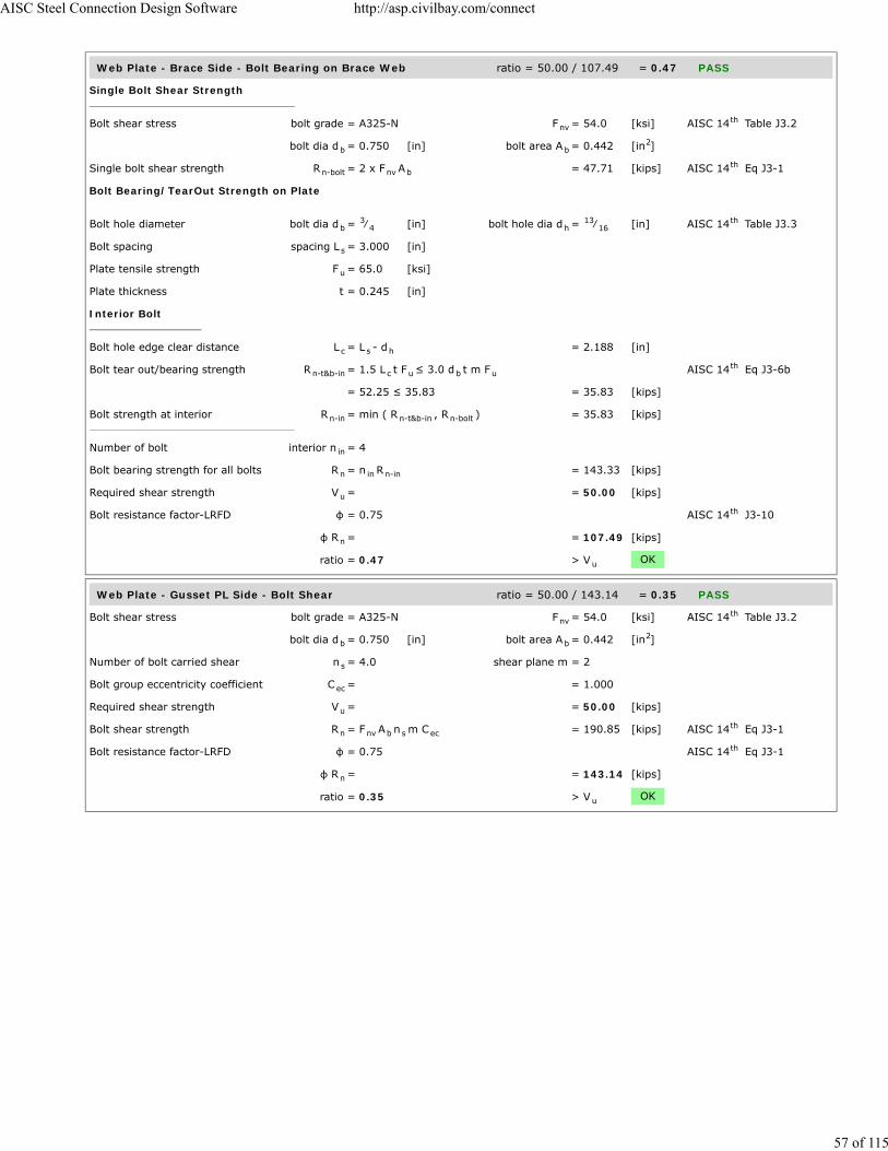
Web Plate - Brace Side - Bolt Bearing on Brace Web ratio = 50.00 / 107.49 = 0.47 PASS
Single Bolt Shear Strength
Bolt shear stress bolt grade = A325-N F = 54.0 [ksi] AISC 14 Table J3.2
bolt dia d = 0.750 [in] bolt area A = 0.442 [in ]
Single bolt shear strength R = 2 x F A = 47.71 [kips] AISC 14 Eq J3-1
Bolt Bearing/TearOut Strength on Plate
Bolt hole diameter bolt dia d = ⁄ [in] bolt hole dia d = ⁄ [in] AISC 14 Table J3.3
Bolt spacing spacing L = 3.000 [in]
Plate tensile strength F = 65.0 [ksi]
Plate thickness t = 0.245 [in]
Interior Bolt
Bolt hole edge clear distance L = L - d = 2.188 [in]
Bolt tear out/bearing strength R = 1.5 L t F ≤ 3.0 d t m F AISC 14 Eq J3-6b
= 52.25 ≤ 35.83 = 35.83 [kips]
Bolt strength at interior R = min ( R , R ) = 35.83 [kips]
Number of bolt interior n = 4
Bolt bearing strength for all bolts R = n R = 143.33 [kips]
Required shear strength V = = 50.00 [kips]
Bolt resistance factor-LRFD φ = 0.75 AISC 14 J3-10
φ R = = 107.49 [kips]
ratio = 0.47 > V OK
Web Plate - Gusset PL Side - Bolt Shear ratio = 50.00 / 143.14 = 0.35 PASS
Bolt shear stress bolt grade = A325-N F = 54.0 [ksi] AISC 14 Table J3.2
bolt dia d = 0.750 [in] bolt area A = 0.442 [in ]
Number of bolt carried shear n = 4.0 shear plane m = 2
Bolt group eccentricity coefficient C = = 1.000
Required shear strength V = = 50.00 [kips]
Bolt shear strength R = F A n m C = 190.85 [kips] AISC 14 Eq J3-1
Bolt resistance factor-LRFD φ = 0.75 AISC 14 Eq J3-1
φ R = = 143.14 [kips]
ratio = 0.35 > V OK
nvth
b b2
n-bolt nv bth
b3
4 h13
16th
s
u
c s h
n-t&b-in c u b uth
n-in n-t&b-in n-bolt
in
n in n-in
u
th
n
u
nvth
b b2
s
ec
u
n nv b s ecth
th
n
u
AISC Steel Connection Design Software http://asp.civilbay.com/connect
57 of 115

Web Plate - Gusset PL Side - Bolt Bearing on Web Plate ratio = 25.00 / 71.57 = 0.35 PASS
Single Bolt Shear Strength
Bolt shear stress bolt grade = A325-N F = 54.0 [ksi] AISC 14 Table J3.2
bolt dia d = 0.750 [in] bolt area A = 0.442 [in ]
Single bolt shear strength R = F A = 23.86 [kips] AISC 14 Eq J3-1
Bolt Bearing/TearOut Strength on Plate
Bolt hole diameter bolt dia d = ⁄ [in] bolt hole dia d = ⁄ [in] AISC 14 Table J3.3
Bolt spacing spacing L = 3.000 [in]
Plate tensile strength F = 65.0 [ksi]
Plate thickness t = 0.375 [in]
Interior Bolt
Bolt hole edge clear distance L = L - d = 2.188 [in]
Bolt tear out/bearing strength R = 1.5 L t F ≤ 3.0 d t m F AISC 14 Eq J3-6b
= 79.98 ≤ 54.84 = 54.84 [kips]
Bolt strength at interior R = min ( R , R ) = 23.86 [kips]
Number of bolt interior n = 4
Bolt bearing strength for all bolts R = n R = 95.43 [kips]
Required shear strength V = = 25.00 [kips]
Bolt resistance factor-LRFD φ = 0.75 AISC 14 J3-10
φ R = = 71.57 [kips]
ratio = 0.35 > V OK
nvth
b b2
n-bolt nv bth
b3
4 h13
16th
s
u
c s h
n-t&b-in c u b uth
n-in n-t&b-in n-bolt
in
n in n-in
u
th
n
u
AISC Steel Connection Design Software http://asp.civilbay.com/connect
58 of 115

Web Plate - Gusset PL Side - Bolt Bearing on Gusset Plate ratio = 50.00 / 143.14 = 0.35 PASS
Single Bolt Shear Strength
Bolt shear stress bolt grade = A325-N F = 54.0 [ksi] AISC 14 Table J3.2
bolt dia d = 0.750 [in] bolt area A = 0.442 [in ]
Single bolt shear strength R = 2 x F A = 47.71 [kips] AISC 14 Eq J3-1
Bolt Bearing/TearOut Strength on Plate
Bolt hole diameter bolt dia d = ⁄ [in] bolt hole dia d = ⁄ [in] AISC 14 Table J3.3
Bolt spacing spacing L = 3.000 [in]
Plate tensile strength F = 65.0 [ksi]
Plate thickness t = 0.375 [in]
Interior Bolt
Bolt hole edge clear distance L = L - d = 2.188 [in]
Bolt tear out/bearing strength R = 1.5 L t F ≤ 3.0 d t m F AISC 14 Eq J3-6b
= 79.98 ≤ 54.84 = 54.84 [kips]
Bolt strength at interior R = min ( R , R ) = 47.71 [kips]
Number of bolt interior n = 4
Bolt bearing strength for all bolts R = n R = 190.85 [kips]
Required shear strength V = = 50.00 [kips]
Bolt resistance factor-LRFD φ = 0.75 AISC 14 J3-10
φ R = = 143.14 [kips]
ratio = 0.35 > V OK
nvth
b b2
n-bolt nv bth
b3
4 h13
16th
s
u
c s h
n-t&b-in c u b uth
n-in n-t&b-in n-bolt
in
n in n-in
u
th
n
u
AISC Steel Connection Design Software http://asp.civilbay.com/connect
59 of 115

Web Plate - Compression Buckling ratio = 25.00 / 73.02 = 0.34 PASS
Plate Compression Check
Plate size width b = 5.750 [in] thickness t = 0.375 [in]
F = 50.0 [ksi] E = 29000 [ksi]
Plate gross area in compression A = b t = 2.156 [in ]
Plate radius of gyration r = t / 12 = 0.108 [in]
Plate effective length factor K = = 1.00
Plate unbraced length L = = 6.750 [in]
Plate slenderness KL/r = 1.00 x L / r = 62.35
when KL
r > 25 , use Chapter E AISC 14 J4.4 (b)
Elastic buckling stress F = π E
( KL/r ) = 73.62 [ksi] AISC 14 Eq E3-4
when KL
r ≤ 4.71 (
E
F ) = 113.43 AISC 14 E3 (a)
Critical stress F = 0.658 F = 37.63 [ksi] AISC 14 Eq E3-2
Plate compression required P = = 25.00 [kips]
Plate compression provided R = F x A = 81.13 [kips] AISC 14 Eq E3-1
Bolt resistance factor-LRFD φ = 0.90 AISC 14 E1
φ R = = 73.02 [kips]
ratio = 0.34 > P OK
p p
y
g p p2
p √
u
u
th
e
2
2th
y
0.5 th
cr( F / F )y e
yth
u
n cr gth
th
n
u
AISC Steel Connection Design Software http://asp.civilbay.com/connect
60 of 115

Gusset Plate - Compression (Whitmore) ratio = 50.00 / 103.76 = 0.48 PASS
Plate Compression Check
Plate size width b = 6.464 [in] thickness t = 0.375 [in]
F = 50.0 [ksi] E = 29000 [ksi]
Plate gross area in compression A = b t = 2.424 [in ]
Plate radius of gyration r = t / 12 = 0.108 [in]
Plate effective length factor K = = 0.50
Plate unbraced length L = = 5.664 [in]
Plate slenderness KL/r = 0.50 x L / r = 26.16
when KL
r > 25 , use Chapter E AISC 14 J4.4 (b)
Elastic buckling stress F = π E
( KL/r ) = 418.21 [ksi] AISC 14 Eq E3-4
when KL
r ≤ 4.71 (
E
F ) = 113.43 AISC 14 E3 (a)
Critical stress F = 0.658 F = 47.56 [ksi] AISC 14 Eq E3-2
Plate compression required P = = 50.00 [kips]
Plate compression provided R = F x A = 115.28 [kips] AISC 14 Eq E3-1
Bolt resistance factor-LRFD φ = 0.90 AISC 14 E1
φ R = = 103.76 [kips]
ratio = 0.48 > P OK
Brace Force Load Case 2 Sect=W8X24 P =-50.00 kips (T) ratio = 0.69 PASS
W Shape Brace - Tensile Yield ratio = 50.00 / 318.60 = 0.16 PASS
Gross area subject to tension A = = 7.080 [in ]
Steel yield strength F = = 50.0 [ksi]
Tensile force required P = = 50.00 [kips]
Tensile yielding strength R = F A = 354.00 [kips] AISC 14 Eq D2-1
Resistance factor-LRFD φ = 0.90 AISC 14 D2 (a)
φ R = = 318.60 [kips] AISC 14 Eq D2-1
ratio = 0.16 > P OK
p p
y
g p p2
p √
u
u
th
e
2
2th
y
0.5 th
cr( F / F )y e
yth
u
n cr gth
th
n
u
g2
y
u
n y gth
th
nth
u
AISC Steel Connection Design Software http://asp.civilbay.com/connect
61 of 115
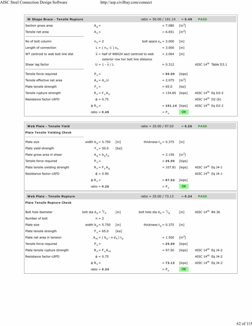
W Shape Brace - Tensile Rupture ratio = 50.00 / 101.14 = 0.49 PASS
Section gross area A = = 7.080 [in ]
Tensile net area A = = 6.651 [in ]
No of bolt column n = 2 bolt space s = 3.000 [in]
Length of connection L = ( n -1 ) s = 3.000 [in]
WT centroid to web bolt line dist x = half of W8X24 sect centroid to web = 2.064 [in]
exterior row hor bolt line distance
Shear lag factor U = 1 - x / L = 0.312 AISC 14 Table D3.1
Tensile force required P = = 50.00 [kips]
Tensile effective net area A = A U = 2.075 [in ]
Plate tensile strength F = = 65.0 [ksi]
Tensile rupture strength R = F A = 134.85 [kips] AISC 14 Eq D2-2
Resistance factor-LRFD φ = 0.75 AISC 14 D2 (b)
φ R = = 101.14 [kips] AISC 14 Eq D2-2
ratio = 0.49 > P OK
Web Plate - Tensile Yield ratio = 25.00 / 97.03 = 0.26 PASS
Plate Tensile Yielding Check
Plate size width b = 5.750 [in] thickness t = 0.375 [in]
Plate yield strength F = 50.0 [ksi]
Plate gross area in shear A = b t = 2.156 [in ]
Tensile force required P = = 25.00 [kips]
Plate tensile yielding strength R = F A = 107.81 [kips] AISC 14 Eq J4-1
Resistance factor-LRFD φ = 0.90 AISC 14 Eq J4-1
φ R = = 97.03 [kips]
ratio = 0.26 > P OK
Web Plate - Tensile Rupture ratio = 25.00 / 73.13 = 0.34 PASS
Plate Tensile Rupture Check
Bolt hole diameter bolt dia d = ⁄ [in] bolt hole dia d = ⁄ [in] AISC 14 B4.3b
Number of bolt n = 2
Plate size width b = 5.750 [in] thickness t = 0.375 [in]
Plate tensile strength F = 65.0 [ksi]
Plate net area in tension A = ( b - n d ) t = 1.500 [in ]
Tensile force required P = = 25.00 [kips]
Plate tensile rupture strength R = F A = 97.50 [kips] AISC 14 Eq J4-2
Resistance factor-LRFD φ = 0.75 AISC 14 Eq J4-2
φ R = = 73.13 [kips] AISC 14 Eq J4-2
ratio = 0.34 > P OK
g2
n2
h h
h h
th
u
e n2
u
n u eth
th
nth
u
p p
y
g p p2
u
n y gth
th
n
u
b3
4 h7
8th
p p
u
nt p h p2
u
n u ntth
th
nth
u
AISC Steel Connection Design Software http://asp.civilbay.com/connect
62 of 115

Web Plate - Brace Side - Bolt Shear ratio = 50.00 / 143.14 = 0.35 PASS
Bolt shear stress bolt grade = A325-N F = 54.0 [ksi] AISC 14 Table J3.2
bolt dia d = 0.750 [in] bolt area A = 0.442 [in ]
Number of bolt carried shear n = 4.0 shear plane m = 2
Bolt group eccentricity coefficient C = = 1.000
Required shear strength V = = 50.00 [kips]
Bolt shear strength R = F A n m C = 190.85 [kips] AISC 14 Eq J3-1
Bolt resistance factor-LRFD φ = 0.75 AISC 14 Eq J3-1
φ R = = 143.14 [kips]
ratio = 0.35 > V OK
Web Plate - Brace Side - Bolt Bearing on Web Plate ratio = 25.00 / 71.57 = 0.35 PASS
Single Bolt Shear Strength
Bolt shear stress bolt grade = A325-N F = 54.0 [ksi] AISC 14 Table J3.2
bolt dia d = 0.750 [in] bolt area A = 0.442 [in ]
Single bolt shear strength R = F A = 23.86 [kips] AISC 14 Eq J3-1
Bolt Bearing/TearOut Strength on Plate
Bolt hole diameter bolt dia d = ⁄ [in] bolt hole dia d = ⁄ [in] AISC 14 Table J3.3
Bolt spacing & edge distance spacing L = 3.000 [in] edge distance L = 1.375 [in]
Plate tensile strength F = 65.0 [ksi]
Plate thickness t = 0.375 [in]
Interior Bolt
Bolt hole edge clear distance L = L - d = 2.188 [in]
Bolt tear out/bearing strength R = 1.5 L t F ≤ 3.0 d t F AISC 14 Eq J3-6b
= 79.98 ≤ 54.84 = 54.84 [kips]
Bolt strength at interior R = min ( R , R ) = 23.86 [kips]
Edge Bolt
Bolt hole edge clear distance L = L - d / 2 = 0.969 [in]
Bolt tear out/bearing strength R = 1.5 L t F ≤ 3.0 d t F AISC 14 Eq J3-6b
= 35.42 ≤ 54.84 = 35.42 [kips]
Bolt strength at edge R = min ( R , R ) = 23.86 [kips]
Number of bolt interior n = 2 edge n = 2
Bolt bearing strength for all bolts R = n R + n R = 95.43 [kips]
Required shear strength V = = 25.00 [kips]
Bolt resistance factor-LRFD φ = 0.75 AISC 14 J3-10
φ R = = 71.57 [kips]
ratio = 0.35 > V OK
nvth
b b2
s
ec
u
n nv b s ecth
th
n
u
nvth
b b2
n-bolt nv bth
b3
4 h13
16th
s e
u
c s h
n-t&b-in c u b uth
n-in n-t&b-in n-bolt
c e h
n-t&b-ed c u b uth
n-ed n-t&b-ed n-bolt
in ed
n in n-in ed n-ed
u
th
n
u
AISC Steel Connection Design Software http://asp.civilbay.com/connect
63 of 115

Web Plate - Brace Side - Bolt Bearing on Brace Web ratio = 50.00 / 97.42 = 0.51 PASS
Single Bolt Shear Strength
Bolt shear stress bolt grade = A325-N F = 54.0 [ksi] AISC 14 Table J3.2
bolt dia d = 0.750 [in] bolt area A = 0.442 [in ]
Single bolt shear strength R = 2 x F A = 47.71 [kips] AISC 14 Eq J3-1
Bolt Bearing/TearOut Strength on Plate
Bolt hole diameter bolt dia d = ⁄ [in] bolt hole dia d = ⁄ [in] AISC 14 Table J3.3
Bolt spacing & edge distance spacing L = 3.000 [in] edge distance L = 1.625 [in]
Plate tensile strength F = 65.0 [ksi]
Plate thickness t = 0.245 [in]
Interior Bolt
Bolt hole edge clear distance L = L - d = 2.188 [in]
Bolt tear out/bearing strength R = 1.5 L t F ≤ 3.0 d t F AISC 14 Eq J3-6b
= 52.25 ≤ 35.83 = 35.83 [kips]
Bolt strength at interior R = min ( R , R ) = 35.83 [kips]
Edge Bolt
Bolt hole edge clear distance L = L - d / 2 = 1.219 [in]
Bolt tear out/bearing strength R = 1.5 L t F ≤ 3.0 d t F AISC 14 Eq J3-6b
= 29.11 ≤ 35.83 = 29.11 [kips]
Bolt strength at edge R = min ( R , R ) = 29.11 [kips]
Number of bolt interior n = 2 edge n = 2
Bolt bearing strength for all bolts R = n R + n R = 129.89 [kips]
Required shear strength V = = 50.00 [kips]
Bolt resistance factor-LRFD φ = 0.75 AISC 14 J3-10
φ R = = 97.42 [kips]
ratio = 0.51 > V OK
nvth
b b2
n-bolt nv bth
b3
4 h13
16th
s e
u
c s h
n-t&b-in c u b uth
n-in n-t&b-in n-bolt
c e h
n-t&b-ed c u b uth
n-ed n-t&b-ed n-bolt
in ed
n in n-in ed n-ed
u
th
n
u
AISC Steel Connection Design Software http://asp.civilbay.com/connect
64 of 115

Web Plate - Block Shear - Center Strip ratio = 25.00 / 106.03 = 0.24 PASS
Plate Block Shear - Center Strip
Bolt hole diameter bolt dia d = ⁄ [in] bolt hole dia d = ⁄ [in] AISC 14 B4.3b
Plate thickness t = 0.375 [in]
Plate strength F = 50.0 [ksi] F = 65.0 [ksi]
Bolt no in ver & hor dir n = 2 n = 2
Bolt spacing in ver & hor dir s = 3.000 [in] s = 3.000 [in]
Bolt edge dist in ver & hor dir e = 1.375 [in] e = 1.375 [in]
Gross area subject to shear A = [ (n - 1) s + e ] t x 2 = 3.281 [in ]
Net area subject to shear A = A - [(n - 1)+ 0.5] d t x2 = 2.297 [in ]
Net area subject to tension
when sheared out by center strip A = ( n - 1) ( s - d ) t = 0.797 [in ]
Block shear strength required V = = 25.00 [kips]
Uniform tension stress factor U = 1.00 AISC 14 Fig C-J4.2
Bolt shear resistance provided R = min (0.6F A , 0.6F A ) + = 141.38 [kips] AISC 14 Eq J4-5
U F A
Resistance factor-LRFD φ = 0.75 AISC 14 Eq J4-5
φ R = = 106.03 [kips]
ratio = 0.24 > V OK
Web Plate - Block Shear - 1-Side Strip ratio = 25.00 / 89.58 = 0.28 PASS
Plate Block Shear - Side Strip
Bolt hole diameter bolt dia d = ⁄ [in] bolt hole dia d = ⁄ [in] AISC 14 B4.3b
Plate thickness t = 0.375 [in]
Plate strength F = 50.0 [ksi] F = 65.0 [ksi]
Bolt no in ver & hor dir n = 2 n = 2
Bolt spacing in ver & hor dir s = 3.000 [in] s = 3.000 [in]
Bolt edge dist in ver & hor dir e = 1.375 [in] e = 1.375 [in]
Gross area subject to shear A = [ (n - 1) s + e ] t = 1.641 [in ]
Net area subject to shear A = A - [(n - 1)+ 0.5] d t = 1.148 [in ]
Net area subject to tension
when sheared out by side strip A = [(n -1)s +e -((n - 1)+0.5)d ] t = 1.148 [in ]
Block shear strength required V = = 25.00 [kips]
Uniform tension stress factor U = 1.00 AISC 14 Fig C-J4.2
Bolt shear resistance provided R = min (0.6F A , 0.6F A ) + = 119.44 [kips] AISC 14 Eq J4-5
U F A
Resistance factor-LRFD φ = 0.75 AISC 14 Eq J4-5
φ R = = 89.58 [kips]
ratio = 0.28 > V OK
b3
4 h7
8th
p
y u
v h
v h
v h
gv h h h p2
nv gv h h p2
nt v v h p2
u
bsth
n u nv y gvth
bs u ntth
n
u
b3
4 h7
8th
p
y u
v h
v h
v h
gv h h h p2
nv gv h h p2
nt v v v v h p2
u
bsth
n u nv y gvth
bs u ntth
n
u
AISC Steel Connection Design Software http://asp.civilbay.com/connect
65 of 115

Web Plate - Block Shear - 2-Side Strip ratio = 25.00 / 101.46 = 0.25 PASS
Plate Block Shear - 2 Side Strips
Bolt hole diameter bolt dia d = ⁄ [in] bolt hole dia d = ⁄ [in] AISC 14 B4.3b
Plate thickness t = 0.375 [in]
Plate strength F = 50.0 [ksi] F = 65.0 [ksi]
Bolt no in ver & hor dir n = 2 n = 2
Bolt spacing in ver & hor dir s = 3.000 [in] s = 3.000 [in]
Bolt edge dist in ver & hor dir e = 1.375 [in] e = 1.375 [in]
Gross area subject to shear A = [ (n - 1) s + e ] t x 2 = 3.281 [in ]
Net area subject to shear A = A - [(n - 1)+ 0.5] d t x2 = 2.297 [in ]
Net area subject to tension
when sheared out by 2 side strips A = ( e - 0.5 d ) t x 2 = 0.703 [in ]
Block shear strength required V = = 25.00 [kips]
Uniform tension stress factor U = 1.00 AISC 14 Fig C-J4.2
Bolt shear resistance provided R = min (0.6F A , 0.6F A ) + = 135.28 [kips] AISC 14 Eq J4-5
U F A
Resistance factor-LRFD φ = 0.75 AISC 14 Eq J4-5
φ R = = 101.46 [kips]
ratio = 0.25 > V OK
Brace Web - Block Shear - Center Strip ratio = 50.00 / 72.86 = 0.69 PASS
Plate Block Shear - Center Strip
Bolt hole diameter bolt dia d = ⁄ [in] bolt hole dia d = ⁄ [in] AISC 14 B4.3b
Plate thickness t = 0.245 [in]
Plate strength F = 50.0 [ksi] F = 65.0 [ksi]
Bolt no in ver & hor dir n = 2 n = 2
Bolt spacing in ver & hor dir s = 3.000 [in] s = 3.000 [in]
Bolt edge dist in ver & hor dir e = 2.465 [in] e = 1.625 [in]
Gross area subject to shear A = [ (n - 1) s + e ] t x 2 = 2.266 [in ]
Net area subject to shear A = A - [(n - 1)+ 0.5] d t x2 = 1.623 [in ]
Net area subject to tension
when sheared out by center strip A = ( n - 1) ( s - d ) t = 0.521 [in ]
Block shear strength required V = = 50.00 [kips]
Uniform tension stress factor U = 1.00 AISC 14 Fig C-J4.2
Bolt shear resistance provided R = min (0.6F A , 0.6F A ) + = 97.14 [kips] AISC 14 Eq J4-5
U F A
Resistance factor-LRFD φ = 0.75 AISC 14 Eq J4-5
φ R = = 72.86 [kips]
ratio = 0.69 > V OK
b3
4 h7
8th
p
y u
v h
v h
v h
gv h h h p2
nv gv h h p2
nt v h p2
u
bsth
n u nv y gvth
bs u ntth
n
u
b3
4 h7
8th
p
y u
v h
v h
v h
gv h h h p2
nv gv h h p2
nt v v h p2
u
bsth
n u nv y gvth
bs u ntth
n
u
AISC Steel Connection Design Software http://asp.civilbay.com/connect
66 of 115

Web Plate - Gusset PL Side - Bolt Shear ratio = 50.00 / 143.14 = 0.35 PASS
Bolt shear stress bolt grade = A325-N F = 54.0 [ksi] AISC 14 Table J3.2
bolt dia d = 0.750 [in] bolt area A = 0.442 [in ]
Number of bolt carried shear n = 4.0 shear plane m = 2
Bolt group eccentricity coefficient C = = 1.000
Required shear strength V = = 50.00 [kips]
Bolt shear strength R = F A n m C = 190.85 [kips] AISC 14 Eq J3-1
Bolt resistance factor-LRFD φ = 0.75 AISC 14 Eq J3-1
φ R = = 143.14 [kips]
ratio = 0.35 > V OK
Web Plate - Gusset PL Side - Bolt Bearing on Web Plate ratio = 25.00 / 71.57 = 0.35 PASS
Single Bolt Shear Strength
Bolt shear stress bolt grade = A325-N F = 54.0 [ksi] AISC 14 Table J3.2
bolt dia d = 0.750 [in] bolt area A = 0.442 [in ]
Single bolt shear strength R = F A = 23.86 [kips] AISC 14 Eq J3-1
Bolt Bearing/TearOut Strength on Plate
Bolt hole diameter bolt dia d = ⁄ [in] bolt hole dia d = ⁄ [in] AISC 14 Table J3.3
Bolt spacing & edge distance spacing L = 3.000 [in] edge distance L = 1.375 [in]
Plate tensile strength F = 65.0 [ksi]
Plate thickness t = 0.375 [in]
Interior Bolt
Bolt hole edge clear distance L = L - d = 2.188 [in]
Bolt tear out/bearing strength R = 1.5 L t F ≤ 3.0 d t F AISC 14 Eq J3-6b
= 79.98 ≤ 54.84 = 54.84 [kips]
Bolt strength at interior R = min ( R , R ) = 23.86 [kips]
Edge Bolt
Bolt hole edge clear distance L = L - d / 2 = 0.969 [in]
Bolt tear out/bearing strength R = 1.5 L t F ≤ 3.0 d t F AISC 14 Eq J3-6b
= 35.42 ≤ 54.84 = 35.42 [kips]
Bolt strength at edge R = min ( R , R ) = 23.86 [kips]
Number of bolt interior n = 2 edge n = 2
Bolt bearing strength for all bolts R = n R + n R = 95.43 [kips]
Required shear strength V = = 25.00 [kips]
Bolt resistance factor-LRFD φ = 0.75 AISC 14 J3-10
φ R = = 71.57 [kips]
ratio = 0.35 > V OK
nvth
b b2
s
ec
u
n nv b s ecth
th
n
u
nvth
b b2
n-bolt nv bth
b3
4 h13
16th
s e
u
c s h
n-t&b-in c u b uth
n-in n-t&b-in n-bolt
c e h
n-t&b-ed c u b uth
n-ed n-t&b-ed n-bolt
in ed
n in n-in ed n-ed
u
th
n
u
AISC Steel Connection Design Software http://asp.civilbay.com/connect
67 of 115

Web Plate - Gusset PL Side - Bolt Bearing on Gusset Plate ratio = 50.00 / 138.41 = 0.36 PASS
Single Bolt Shear Strength
Bolt shear stress bolt grade = A325-N F = 54.0 [ksi] AISC 14 Table J3.2
bolt dia d = 0.750 [in] bolt area A = 0.442 [in ]
Single bolt shear strength R = 2 x F A = 47.71 [kips] AISC 14 Eq J3-1
Bolt Bearing/TearOut Strength on Plate
Bolt hole diameter bolt dia d = ⁄ [in] bolt hole dia d = ⁄ [in] AISC 14 Table J3.3
Bolt spacing & edge distance spacing L = 3.000 [in] edge distance L = 1.625 [in]
Plate tensile strength F = 65.0 [ksi]
Plate thickness t = 0.375 [in]
Interior Bolt
Bolt hole edge clear distance L = L - d = 2.188 [in]
Bolt tear out/bearing strength R = 1.5 L t F ≤ 3.0 d t F AISC 14 Eq J3-6b
= 79.98 ≤ 54.84 = 54.84 [kips]
Bolt strength at interior R = min ( R , R ) = 47.71 [kips]
Edge Bolt
Bolt hole edge clear distance L = L - d / 2 = 1.219 [in]
Bolt tear out/bearing strength R = 1.5 L t F ≤ 3.0 d t F AISC 14 Eq J3-6b
= 44.56 ≤ 54.84 = 44.56 [kips]
Bolt strength at edge R = min ( R , R ) = 44.56 [kips]
Number of bolt interior n = 2 edge n = 2
Bolt bearing strength for all bolts R = n R + n R = 184.55 [kips]
Required shear strength V = = 50.00 [kips]
Bolt resistance factor-LRFD φ = 0.75 AISC 14 J3-10
φ R = = 138.41 [kips]
ratio = 0.36 > V OK
nvth
b b2
n-bolt nv bth
b3
4 h13
16th
s e
u
c s h
n-t&b-in c u b uth
n-in n-t&b-in n-bolt
c e h
n-t&b-ed c u b uth
n-ed n-t&b-ed n-bolt
in ed
n in n-in ed n-ed
u
th
n
u
AISC Steel Connection Design Software http://asp.civilbay.com/connect
68 of 115

Gusset Plate at Web Plate - Block Shear - Center Strip ratio = 50.00 / 111.52 = 0.45 PASS
Plate Block Shear - Center Strip
Bolt hole diameter bolt dia d = ⁄ [in] bolt hole dia d = ⁄ [in] AISC 14 B4.3b
Plate thickness t = 0.375 [in]
Plate strength F = 50.0 [ksi] F = 65.0 [ksi]
Bolt no in ver & hor dir n = 2 n = 2
Bolt spacing in ver & hor dir s = 3.000 [in] s = 3.000 [in]
Bolt edge dist in ver & hor dir e = 2.465 [in] e = 1.625 [in]
Gross area subject to shear A = [ (n - 1) s + e ] t x 2 = 3.469 [in ]
Net area subject to shear A = A - [(n - 1)+ 0.5] d t x2 = 2.484 [in ]
Net area subject to tension
when sheared out by center strip A = ( n - 1) ( s - d ) t = 0.797 [in ]
Block shear strength required V = = 50.00 [kips]
Uniform tension stress factor U = 1.00 AISC 14 Fig C-J4.2
Bolt shear resistance provided R = min (0.6F A , 0.6F A ) + = 148.69 [kips] AISC 14 Eq J4-5
U F A
Resistance factor-LRFD φ = 0.75 AISC 14 Eq J4-5
φ R = = 111.52 [kips]
ratio = 0.45 > V OK
Gusset Plate - Tensile Yield (Whitmore) ratio = 50.00 / 109.08 = 0.46 PASS
Plate Tensile Yielding Check
Plate size width b = 6.464 [in] thickness t = 0.375 [in]
Plate yield strength F = 50.0 [ksi]
Plate gross area in shear A = b t = 2.424 [in ]
Tensile force required P = = 50.00 [kips]
Plate tensile yielding strength R = F A = 121.20 [kips] AISC 14 Eq J4-1
Resistance factor-LRFD φ = 0.90 AISC 14 Eq J4-1
φ R = = 109.08 [kips]
ratio = 0.46 > P OK
Gusset Plate - Tensile Rupture (Whitmore) ratio = 50.00 / 86.18 = 0.58 PASS
Plate Tensile Rupture Check
Bolt hole diameter bolt dia d = ⁄ [in] bolt hole dia d = ⁄ [in] AISC 14 B4.3b
Number of bolt n = 2
Plate size width b = 6.464 [in] thickness t = 0.375 [in]
Plate tensile strength F = 65.0 [ksi]
Plate net area in tension A = ( b - n d ) t = 1.768 [in ]
Tensile force required P = = 50.00 [kips]
Plate tensile rupture strength R = F A = 114.90 [kips] AISC 14 Eq J4-2
Resistance factor-LRFD φ = 0.75 AISC 14 Eq J4-2
φ R = = 86.18 [kips] AISC 14 Eq J4-2
ratio = 0.58 > P OK
b3
4 h7
8th
p
y u
v h
v h
v h
gv h h h p2
nv gv h h p2
nt v v h p2
u
bsth
n u nv y gvth
bs u ntth
n
u
p p
y
g p p2
u
n y gth
th
n
u
b3
4 h7
8th
p p
u
nt p h p2
u
n u ntth
th
nth
u
AISC Steel Connection Design Software http://asp.civilbay.com/connect
69 of 115

Bottom Brace - Gusset to Column End Plate Connection Code=AISC 360-10 LRFD
Result Summary geometries & weld limitations = PASS limit states max ratio = 0.21 PASS
Geometry Restriction Checks - End Plate to Column Web PASS
Min Bolt Edge Distance - End Plate to Column Web
Bolt diameter d = = 0.750 [in]
Min edge distance allowed L = = 1.000 [in] AISC 14 Table J3.4
Min edge distance in End Plate toColumn Web
L = = 1.375 [in]
> L OK
Min Bolt Spacing - End Plate to Column Web
Bolt diameter d = = 0.750 [in]
Min bolt spacing allowed L = 2.667 d = 2.000 [in] AISC 14 J3.3
Min Bolt spacing in End Plate toColumn Web
L = = 3.000 [in]
> L OK
Weld Limitation Checks - Gusset Plate to End Plate PASS
Min Fillet Weld Size
Thinner part joined thickness t = = 0.375 [in]
Min fillet weld size allowed w = = 0.188 [in] AISC 14 Table J2.4
Fillet weld size provided w = = 0.313 [in]
> w OK
Min Fillet Weld Length
Fillet weld size provided w = = 0.313 [in]
Min fillet weld length allowed L = 4 x w = 1.250 [in] AISC 14 J2.2b
Min fillet weld length L = = 6.625 [in]
> L OK
Brace Force Load Case 1 Gusset plate t=0.375 P =50.00 kips (C) ratio = 0.21 PASS
Gusset Plate - Shear Yielding ratio = 15.08 / 74.53 = 0.20 PASS
Plate Shear Yielding Check
Plate size width b = 6.625 [in] thickness t = 0.375 [in]
Plate yield strength F = 50.0 [ksi]
Plate gross area in shear A = b t = 2.484 [in ]
Shear force required V = = 15.08 [kips]
Plate shear yielding strength R = 0.6 F A = 74.53 [kips] AISC 14 Eq J4-3
Resistance factor-LRFD φ = 1.00 AISC 14 Eq J4-3
φ R = = 74.53 [kips]
ratio = 0.20 > V OK
b
e-minth
e
e-min
b
s-min bth
s
s-min
minth
min
minth
min
p p
y
gv p p2
u
n y gvth
th
n
u
AISC Steel Connection Design Software http://asp.civilbay.com/connect
70 of 115

Gusset Plate - Shear Rupture ratio = 15.08 / 72.67 = 0.21 PASS
Plate Shear Rupture Check
Plate size width b = 6.625 [in] thickness t = 0.375 [in]
Plate tensile strength F = 65.0 [ksi]
Plate net area in shear A = b t = 2.484 [in ]
Shear force in demand V = = 15.08 [kips]
Plate shear rupture strength R = 0.6 F A = 96.89 [kips] AISC 14 Eq J4-4
Resistance factor-LRFD φ = 0.75 AISC 14 Eq J4-4
φ R = = 72.67 [kips]
ratio = 0.21 > V OK
End Plate - Shear Yield ratio = 7.54 / 64.69 = 0.12 PASS
Plate Shear Yielding Check
Plate size width b = 5.750 [in] thickness t = 0.375 [in]
Plate yield strength F = 50.0 [ksi]
Plate gross area in shear A = b t = 2.156 [in ]
Shear force required V = = 7.54 [kips]
Plate shear yielding strength R = 0.6 F A = 64.69 [kips] AISC 14 Eq J4-3
Resistance factor-LRFD φ = 1.00 AISC 14 Eq J4-3
φ R = = 64.69 [kips]
ratio = 0.12 > V OK
End Plate - Shear Rupture ratio = 7.54 / 43.88 = 0.17 PASS
Plate Shear Rupture Check
Bolt hole diameter bolt dia d = ⁄ [in] bolt hole dia d = ⁄ [in] AISC 14 B4.3b
Number of bolt n = 2
Plate size width b = 5.750 [in] thickness t = 0.375 [in]
Plate tensile strength F = 65.0 [ksi]
Plate net area in shear A = ( b - n d ) t = 1.500 [in ]
Shear force required V = = 7.54 [kips]
Plate shear rupture strength R = 0.6 F A = 58.50 [kips] AISC 14 Eq J4-4
Resistance factor-LRFD φ = 0.75 AISC 14 Eq J4-4
φ R = = 43.88 [kips]
ratio = 0.17 > V OK
p p
u
nv p p2
u
n u nvth
th
n
u
p p
y
gv p p2
u
n y gvth
th
n
u
b3
4 h7
8th
p p
u
nv p h p2
u
n u nvth
th
n
u
AISC Steel Connection Design Software http://asp.civilbay.com/connect
71 of 115

End Plate - Block Shear - Center Strip ratio = 15.08 / 124.31 = 0.12 PASS
Plate Block Shear - Center Strip
Bolt hole diameter bolt dia d = ⁄ [in] bolt hole dia d = ⁄ [in] AISC 14 B4.3b
Plate thickness t = 0.375 [in]
Plate strength F = 50.0 [ksi] F = 65.0 [ksi]
Bolt no in ver & hor dir n = 2 n = 2
Bolt spacing in ver & hor dir s = 4.000 [in] s = 3.000 [in]
Bolt edge dist in ver & hor dir e = 1.375 [in] e = 1.375 [in]
Gross area subject to shear A = [ (n - 1) s + e ] t x 2 = 3.281 [in ]
Net area subject to shear A = A - [(n - 1)+ 0.5] d t x2 = 2.297 [in ]
Net area subject to tension
when sheared out by center strip A = ( n - 1) ( s - d ) t = 1.172 [in ]
Block shear strength required V = = 15.08 [kips]
Uniform tension stress factor U = 1.00 AISC 14 Fig C-J4.2
Bolt shear resistance provided R = min (0.6F A , 0.6F A ) + = 165.75 [kips] AISC 14 Eq J4-5
U F A
Resistance factor-LRFD φ = 0.75 AISC 14 Eq J4-5
φ R = = 124.31 [kips]
ratio = 0.12 > V OK
End Plate - Block Shear - 2-Side Strip ratio = 15.08 / 101.46 = 0.15 PASS
Plate Block Shear - 2 Side Strips
Bolt hole diameter bolt dia d = ⁄ [in] bolt hole dia d = ⁄ [in] AISC 14 B4.3b
Plate thickness t = 0.375 [in]
Plate strength F = 50.0 [ksi] F = 65.0 [ksi]
Bolt no in ver & hor dir n = 2 n = 2
Bolt spacing in ver & hor dir s = 4.000 [in] s = 3.000 [in]
Bolt edge dist in ver & hor dir e = 1.375 [in] e = 1.375 [in]
Gross area subject to shear A = [ (n - 1) s + e ] t x 2 = 3.281 [in ]
Net area subject to shear A = A - [(n - 1)+ 0.5] d t x2 = 2.297 [in ]
Net area subject to tension
when sheared out by 2 side strips A = ( e - 0.5 d ) t x 2 = 0.703 [in ]
Block shear strength required V = = 15.08 [kips]
Uniform tension stress factor U = 1.00 AISC 14 Fig C-J4.2
Bolt shear resistance provided R = min (0.6F A , 0.6F A ) + = 135.28 [kips] AISC 14 Eq J4-5
U F A
Resistance factor-LRFD φ = 0.75 AISC 14 Eq J4-5
φ R = = 101.46 [kips]
ratio = 0.15 > V OK
b3
4 h7
8th
p
y u
v h
v h
v h
gv h h h p2
nv gv h h p2
nt v v h p2
u
bsth
n u nv y gvth
bs u ntth
n
u
b3
4 h7
8th
p
y u
v h
v h
v h
gv h h h p2
nv gv h h p2
nt v h p2
u
bsth
n u nv y gvth
bs u ntth
n
u
AISC Steel Connection Design Software http://asp.civilbay.com/connect
72 of 115

End Plate - Bolt Bearing on End Plate ratio = 15.08 / 71.57 = 0.21 PASS
Single Bolt Shear Strength
Bolt shear stress bolt grade = A325-N F = 54.0 [ksi] AISC 14 Table J3.2
bolt dia d = 0.750 [in] bolt area A = 0.442 [in ]
Single bolt shear strength R = F A = 23.86 [kips] AISC 14 Eq J3-1
Bolt Bearing/TearOut Strength on Plate
Bolt hole diameter bolt dia d = ⁄ [in] bolt hole dia d = ⁄ [in] AISC 14 Table J3.3
Bolt spacing & edge distance spacing L = 3.000 [in] edge distance L = 1.375 [in]
Plate tensile strength F = 65.0 [ksi]
Plate thickness t = 0.375 [in]
Interior Bolt
Bolt hole edge clear distance L = L - d = 2.188 [in]
Bolt tear out/bearing strength R = 1.5 L t F ≤ 3.0 d t F AISC 14 Eq J3-6b
= 79.98 ≤ 54.84 = 54.84 [kips]
Bolt strength at interior R = min ( R , R ) = 23.86 [kips]
Edge Bolt
Bolt hole edge clear distance L = L - d / 2 = 0.969 [in]
Bolt tear out/bearing strength R = 1.5 L t F ≤ 3.0 d t F AISC 14 Eq J3-6b
= 35.42 ≤ 54.84 = 35.42 [kips]
Bolt strength at edge R = min ( R , R ) = 23.86 [kips]
Number of bolt interior n = 2 edge n = 2
Bolt bearing strength for all bolts R = n R + n R = 95.43 [kips]
Required shear strength V = = 15.08 [kips]
Bolt resistance factor-LRFD φ = 0.75 AISC 14 J3-10
φ R = = 71.57 [kips]
ratio = 0.21 > V OK
End Plate / Column - Bolt Shear ratio = 15.08 / 71.57 = 0.21 PASS
Bolt shear stress bolt grade = A325-N F = 54.0 [ksi] AISC 14 Table J3.2
bolt dia d = 0.750 [in] bolt area A = 0.442 [in ]
Number of bolt carried shear n = 4.0 shear plane m = 1
Bolt group eccentricity coefficient C = = 1.000
Required shear strength V = = 15.08 [kips]
Bolt shear strength R = F A n m C = 95.43 [kips] AISC 14 Eq J3-1
Bolt resistance factor-LRFD φ = 0.75 AISC 14 Eq J3-1
φ R = = 71.57 [kips]
ratio = 0.21 > V OK
nvth
b b2
n-bolt nv bth
b3
4 h13
16th
s e
u
c s h
n-t&b-in c u b uth
n-in n-t&b-in n-bolt
c e h
n-t&b-ed c u b uth
n-ed n-t&b-ed n-bolt
in ed
n in n-in ed n-ed
u
th
n
u
nvth
b b2
s
ec
u
n nv b s ecth
th
n
u
AISC Steel Connection Design Software http://asp.civilbay.com/connect
73 of 115

End Plate / Column - Bolt Bearing on Column ratio = 15.08 / 71.57 = 0.21 PASS
Single Bolt Shear Strength
Bolt shear stress bolt grade = A325-N F = 54.0 [ksi] AISC 14 Table J3.2
bolt dia d = 0.750 [in] bolt area A = 0.442 [in ]
Single bolt shear strength R = F A = 23.86 [kips] AISC 14 Eq J3-1
Bolt Bearing/TearOut Strength on Plate
Bolt hole diameter bolt dia d = ⁄ [in] bolt hole dia d = ⁄ [in] AISC 14 Table J3.3
Bolt spacing spacing L = 3.000 [in]
Plate tensile strength F = 65.0 [ksi]
Plate thickness t = 0.295 [in]
Interior Bolt
Bolt hole edge clear distance L = L - d = 2.188 [in]
Bolt tear out/bearing strength R = 1.5 L t F ≤ 3.0 d t m F AISC 14 Eq J3-6b
= 62.92 ≤ 43.14 = 43.14 [kips]
Bolt strength at interior R = min ( R , R ) = 23.86 [kips]
Number of bolt interior n = 4
Bolt bearing strength for all bolts R = n R = 95.43 [kips]
Required shear strength V = = 15.08 [kips]
Bolt resistance factor-LRFD φ = 0.75 AISC 14 J3-10
φ R = = 71.57 [kips]
ratio = 0.21 > V OK
nvth
b b2
n-bolt nv bth
b3
4 h13
16th
s
u
c s h
n-t&b-in c u b uth
n-in n-t&b-in n-bolt
in
n in n-in
u
th
n
u
AISC Steel Connection Design Software http://asp.civilbay.com/connect
74 of 115

Gusset Plate to End Plate Weld Strength ratio = 2.28 / 10.97 = 0.21 PASS
Weld Group Forces
shear V = 15.08 [kips] axial P = 0.49 [kips] in compression
Gusset-end plate fillet weld length L = weld length tributary to bolt group = 6.625 [in]
Combined Weld Stress
Weld stress from axial force f = P / L = 0.000 [kip/in] in compression
Weld stress from shear force f = V / L = 2.276 [kip/in]
Weld stress combined - max f = f = 2.276 [kip/in] AISC 14 Eq 8-11
Weld stress load angle θ = = 0.0 [°]
Fillet Weld Strength Calc
Fillet weld leg size w = ⁄ [in] load angle θ = 0.0 [°]
Electrode strength F = 70.0 [ksi] strength coeff C = 1.00 AISC 14 Table 8-3
Number of weld line n = 2 for double fillet
Load angle coefficient C = ( 1 + 0.5 sin θ ) = 1.00 AISC 14 Page 8-9
Fillet weld shear strength R = 0.6 (C x 70 ksi) 0.707 w n C = 18.559 [kip/in] AISC 14 Eq 8-1
Base metal - gusset plate thickness t = 0.375 [in] tensile F = 65.0 [ksi]
Base metal - gusset plate is in shear, shear rupture as per AISC 14 Eq J4-4 is checked AISC 14 J2.4
Base metal shear rupture R = 0.6 F t = 14.625 [kip/in] AISC 14 Eq J4-4
Double fillet linear shear strength R = min ( R , R ) = 14.625 [kip/in] AISC 14 Eq 9-2
Resistance factor-LRFD φ = 0.75 AISC 14 Eq 8-1
φ R = = 10.969 [kip/in]
ratio = 0.21 > f OK
Brace Force Load Case 2 Gusset plate t=0.375 P =-50.00 kips (T) ratio = 0.21 PASS
Gusset Plate - Shear Yielding ratio = 15.08 / 74.53 = 0.20 PASS
Plate Shear Yielding Check
Plate size width b = 6.625 [in] thickness t = 0.375 [in]
Plate yield strength F = 50.0 [ksi]
Plate gross area in shear A = b t = 2.484 [in ]
Shear force required V = = 15.08 [kips]
Plate shear yielding strength R = 0.6 F A = 74.53 [kips] AISC 14 Eq J4-3
Resistance factor-LRFD φ = 1.00 AISC 14 Eq J4-3
φ R = = 74.53 [kips]
ratio = 0.20 > V OK
a
v
max vth
516
EXX 1th
21.5 th
n-w 1 2th
u
th th
n-b uth
n n-w n-bth
th
n
max
p p
y
gv p p2
u
n y gvth
th
n
u
AISC Steel Connection Design Software http://asp.civilbay.com/connect
75 of 115

Gusset Plate - Shear Rupture ratio = 15.08 / 72.67 = 0.21 PASS
Plate Shear Rupture Check
Plate size width b = 6.625 [in] thickness t = 0.375 [in]
Plate tensile strength F = 65.0 [ksi]
Plate net area in shear A = b t = 2.484 [in ]
Shear force in demand V = = 15.08 [kips]
Plate shear rupture strength R = 0.6 F A = 96.89 [kips] AISC 14 Eq J4-4
Resistance factor-LRFD φ = 0.75 AISC 14 Eq J4-4
φ R = = 72.67 [kips]
ratio = 0.21 > V OK
End Plate - Shear Yield ratio = 7.54 / 64.69 = 0.12 PASS
Plate Shear Yielding Check
Plate size width b = 5.750 [in] thickness t = 0.375 [in]
Plate yield strength F = 50.0 [ksi]
Plate gross area in shear A = b t = 2.156 [in ]
Shear force required V = = 7.54 [kips]
Plate shear yielding strength R = 0.6 F A = 64.69 [kips] AISC 14 Eq J4-3
Resistance factor-LRFD φ = 1.00 AISC 14 Eq J4-3
φ R = = 64.69 [kips]
ratio = 0.12 > V OK
End Plate - Shear Rupture ratio = 7.54 / 43.88 = 0.17 PASS
Plate Shear Rupture Check
Bolt hole diameter bolt dia d = ⁄ [in] bolt hole dia d = ⁄ [in] AISC 14 B4.3b
Number of bolt n = 2
Plate size width b = 5.750 [in] thickness t = 0.375 [in]
Plate tensile strength F = 65.0 [ksi]
Plate net area in shear A = ( b - n d ) t = 1.500 [in ]
Shear force required V = = 7.54 [kips]
Plate shear rupture strength R = 0.6 F A = 58.50 [kips] AISC 14 Eq J4-4
Resistance factor-LRFD φ = 0.75 AISC 14 Eq J4-4
φ R = = 43.88 [kips]
ratio = 0.17 > V OK
p p
u
nv p p2
u
n u nvth
th
n
u
p p
y
gv p p2
u
n y gvth
th
n
u
b3
4 h7
8th
p p
u
nv p h p2
u
n u nvth
th
n
u
AISC Steel Connection Design Software http://asp.civilbay.com/connect
76 of 115

End Plate - Block Shear - Center Strip ratio = 15.08 / 124.31 = 0.12 PASS
Plate Block Shear - Center Strip
Bolt hole diameter bolt dia d = ⁄ [in] bolt hole dia d = ⁄ [in] AISC 14 B4.3b
Plate thickness t = 0.375 [in]
Plate strength F = 50.0 [ksi] F = 65.0 [ksi]
Bolt no in ver & hor dir n = 2 n = 2
Bolt spacing in ver & hor dir s = 4.000 [in] s = 3.000 [in]
Bolt edge dist in ver & hor dir e = 1.375 [in] e = 1.375 [in]
Gross area subject to shear A = [ (n - 1) s + e ] t x 2 = 3.281 [in ]
Net area subject to shear A = A - [(n - 1)+ 0.5] d t x2 = 2.297 [in ]
Net area subject to tension
when sheared out by center strip A = ( n - 1) ( s - d ) t = 1.172 [in ]
Block shear strength required V = = 15.08 [kips]
Uniform tension stress factor U = 1.00 AISC 14 Fig C-J4.2
Bolt shear resistance provided R = min (0.6F A , 0.6F A ) + = 165.75 [kips] AISC 14 Eq J4-5
U F A
Resistance factor-LRFD φ = 0.75 AISC 14 Eq J4-5
φ R = = 124.31 [kips]
ratio = 0.12 > V OK
End Plate - Block Shear - 2-Side Strip ratio = 15.08 / 101.46 = 0.15 PASS
Plate Block Shear - 2 Side Strips
Bolt hole diameter bolt dia d = ⁄ [in] bolt hole dia d = ⁄ [in] AISC 14 B4.3b
Plate thickness t = 0.375 [in]
Plate strength F = 50.0 [ksi] F = 65.0 [ksi]
Bolt no in ver & hor dir n = 2 n = 2
Bolt spacing in ver & hor dir s = 4.000 [in] s = 3.000 [in]
Bolt edge dist in ver & hor dir e = 1.375 [in] e = 1.375 [in]
Gross area subject to shear A = [ (n - 1) s + e ] t x 2 = 3.281 [in ]
Net area subject to shear A = A - [(n - 1)+ 0.5] d t x2 = 2.297 [in ]
Net area subject to tension
when sheared out by 2 side strips A = ( e - 0.5 d ) t x 2 = 0.703 [in ]
Block shear strength required V = = 15.08 [kips]
Uniform tension stress factor U = 1.00 AISC 14 Fig C-J4.2
Bolt shear resistance provided R = min (0.6F A , 0.6F A ) + = 135.28 [kips] AISC 14 Eq J4-5
U F A
Resistance factor-LRFD φ = 0.75 AISC 14 Eq J4-5
φ R = = 101.46 [kips]
ratio = 0.15 > V OK
b3
4 h7
8th
p
y u
v h
v h
v h
gv h h h p2
nv gv h h p2
nt v v h p2
u
bsth
n u nv y gvth
bs u ntth
n
u
b3
4 h7
8th
p
y u
v h
v h
v h
gv h h h p2
nv gv h h p2
nt v h p2
u
bsth
n u nv y gvth
bs u ntth
n
u
AISC Steel Connection Design Software http://asp.civilbay.com/connect
77 of 115
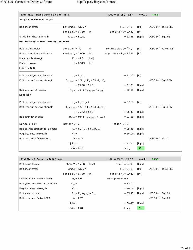
End Plate - Bolt Bearing on End Plate ratio = 15.08 / 71.57 = 0.21 PASS
Single Bolt Shear Strength
Bolt shear stress bolt grade = A325-N F = 54.0 [ksi] AISC 14 Table J3.2
bolt dia d = 0.750 [in] bolt area A = 0.442 [in ]
Single bolt shear strength R = F A = 23.86 [kips] AISC 14 Eq J3-1
Bolt Bearing/TearOut Strength on Plate
Bolt hole diameter bolt dia d = ⁄ [in] bolt hole dia d = ⁄ [in] AISC 14 Table J3.3
Bolt spacing & edge distance spacing L = 3.000 [in] edge distance L = 1.375 [in]
Plate tensile strength F = 65.0 [ksi]
Plate thickness t = 0.375 [in]
Interior Bolt
Bolt hole edge clear distance L = L - d = 2.188 [in]
Bolt tear out/bearing strength R = 1.5 L t F ≤ 3.0 d t F AISC 14 Eq J3-6b
= 79.98 ≤ 54.84 = 54.84 [kips]
Bolt strength at interior R = min ( R , R ) = 23.86 [kips]
Edge Bolt
Bolt hole edge clear distance L = L - d / 2 = 0.969 [in]
Bolt tear out/bearing strength R = 1.5 L t F ≤ 3.0 d t F AISC 14 Eq J3-6b
= 35.42 ≤ 54.84 = 35.42 [kips]
Bolt strength at edge R = min ( R , R ) = 23.86 [kips]
Number of bolt interior n = 2 edge n = 2
Bolt bearing strength for all bolts R = n R + n R = 95.43 [kips]
Required shear strength V = = 15.08 [kips]
Bolt resistance factor-LRFD φ = 0.75 AISC 14 J3-10
φ R = = 71.57 [kips]
ratio = 0.21 > V OK
End Plate / Column - Bolt Shear ratio = 15.08 / 71.57 = 0.21 PASS
Bolt group forces shear V = 15.08 [kips] axial P = 0.49 [kips]
Bolt shear stress grade = A325-N F = 54.0 [ksi] AISC 14 Table J3.2
bolt dia d = 0.750 [in] bolt area A = 0.442 [in ]
Number of bolt carried shear n = 4.0 shear plane m = 1
Bolt group eccentricity coefficient C = = 1.000
Required shear strength V = = 15.08 [kips]
Bolt shear strength R = F A n m C = 95.43 [kips] AISC 14 Eq J3-1
Bolt resistance factor-LRFD φ = 0.75 AISC 14 Eq J3-1
φ R = = 71.57 [kips]
ratio = 0.21 > V OK
nvth
b b2
n-bolt nv bth
b3
4 h13
16th
s e
u
c s h
n-t&b-in c u b uth
n-in n-t&b-in n-bolt
c e h
n-t&b-ed c u b uth
n-ed n-t&b-ed n-bolt
in ed
n in n-in ed n-ed
u
th
n
u
nvth
b b2
s
ec
u
n nv b s ecth
th
n
u
AISC Steel Connection Design Software http://asp.civilbay.com/connect
78 of 115
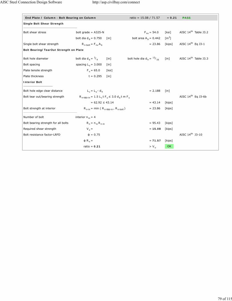
End Plate / Column - Bolt Bearing on Column ratio = 15.08 / 71.57 = 0.21 PASS
Single Bolt Shear Strength
Bolt shear stress bolt grade = A325-N F = 54.0 [ksi] AISC 14 Table J3.2
bolt dia d = 0.750 [in] bolt area A = 0.442 [in ]
Single bolt shear strength R = F A = 23.86 [kips] AISC 14 Eq J3-1
Bolt Bearing/TearOut Strength on Plate
Bolt hole diameter bolt dia d = ⁄ [in] bolt hole dia d = ⁄ [in] AISC 14 Table J3.3
Bolt spacing spacing L = 3.000 [in]
Plate tensile strength F = 65.0 [ksi]
Plate thickness t = 0.295 [in]
Interior Bolt
Bolt hole edge clear distance L = L - d = 2.188 [in]
Bolt tear out/bearing strength R = 1.5 L t F ≤ 3.0 d t m F AISC 14 Eq J3-6b
= 62.92 ≤ 43.14 = 43.14 [kips]
Bolt strength at interior R = min ( R , R ) = 23.86 [kips]
Number of bolt interior n = 4
Bolt bearing strength for all bolts R = n R = 95.43 [kips]
Required shear strength V = = 15.08 [kips]
Bolt resistance factor-LRFD φ = 0.75 AISC 14 J3-10
φ R = = 71.57 [kips]
ratio = 0.21 > V OK
nvth
b b2
n-bolt nv bth
b3
4 h13
16th
s
u
c s h
n-t&b-in c u b uth
n-in n-t&b-in n-bolt
in
n in n-in
u
th
n
u
AISC Steel Connection Design Software http://asp.civilbay.com/connect
79 of 115

Bolt Tensile Prying Action on End Plate ratio = 0.12 / 7.06 = 0.02 PASS
Bolt group forces shear V = 15.08 [kips] axial P = -0.49 [kips]
Single Bolt Tensile Capacity Without Considering Prying
Bolt grade grade = A325-N
Nominal tensile/shear stress F = 90.0 [ksi] F = 54.0 [ksi] AISC 14 Table J3.2
bolt dia d = 0.750 [in] bolt area A = 0.442 [in ]
Bolt group shear force shear V = 15.08 [kips] no of bolt n = 4
Shear stress required f = V / ( n A ) = 8.53 [ksi]
Resistance factor-LRFD φ = 0.75 AISC 14 J3.7
Modified nominal tensile stress F' = 1.3 F - Fφ F
f ≤ F = 90.00 [ksi] AISC 14 Eq J3-3a
Bolt norminal tensile strength r = F' A = 39.76 [kips] AISC 14 Eq J3-1
Resistance factor-LRFD φ = 0.75 AISC 14 J3.6
Single bolt tensile capacity φ r = = 29.82 [kips]
Single Bolt Tensile Capacity After Considering Prying
End plate width w = 6.750 [in] bolt gage g = 4.000 [in]
web t = 0.375 [in]
Dist from bolt center to plate edge a = 0.5 (w - g) = 1.375 [in]
a' = a + 0.5 d ≤ (1.25 b + 0.5 d ) = 1.750 [in] AISC 14 Eq 9-27
Bolt hole diameter bolt dia d = 0.750 [in] bolt hole dia d = 0.813 [in] AISC 14 B4.3b
Dist from bolt center to face of web b = 0.5(g - t ) = 1.813 [in]
b' = b - 0.5 d = 1.438 [in] AISC 14 Eq 9-21
Bolt pitch spacing s = 3.000
Bolt tributary length p = s p ≤ 2b and p ≤ s = 2.875 [in] AISC 14 Page 9-11
ρ = b' / a' = 0.821 AISC 14 Eq 9-26
δ = 1 - d / p = 0.717 AISC 14 Eq 9-24
Tensile capacity per bolt beforeconsidering prying
B = from calc shown in above section = 29.82 [kips]
Resistance factor-LRFD φ = 0.90 AISC 14 Page 9-10
End plate thickness t = 0.375 [in] tensile F = 65.0 [ksi]
Plate thickness req'd to develop bolttensile capacity without prying
t = ( 4 B b'φ p F
) = 1.010 [in] AISC 14 Eq 9-30a
α' = 1δ (1 + ρ )
[ ( tt
) - 1 ] = 4.783 AISC 14 Eq 9-35
when α' > 1 Q = ( tt
) (1 + δ ) = 0.237 AISC 14 Eq 9-34
Bolt tensile force per bolt in demand T = from calc shown below = 0.12 [kips]
Tensile strength per bolt afterconsidering prying
φ r = B x Q = 7.06 [kips] AISC 14 Eq 9-31
ratio = 0.02 > T OK
Calculate Max Single Bolt Tensile Load
Bolt group force axial P = 0.49 [kips]
Bolt number Bolt Row n = 2 Bolt Col n = 2
Bolt tensile force per bolt T = P / ( n n ) = 0.12 [kips]
nt nvth
b b2
rv b
th
nt ntnt
nvrv nt
th
n nt bth
th
n
w
b bth
b hth
w
bth
v
v vth
th
hth
th
u
cu
0.5 th
c 2 th
c
2 th
nth
h v
v h
AISC Steel Connection Design Software http://asp.civilbay.com/connect
80 of 115

Gusset Plate to End Plate Weld Strength ratio = 2.28 / 10.97 = 0.21 PASS
Weld Group Forces
shear V = 15.08 [kips] axial P = -0.49 [kips] in tension
Gusset-end plate fillet weld length L = weld length tributary to bolt group = 6.625 [in]
Combined Weld Stress
Weld stress from axial force f = P / L = -0.074 [kip/in] in tension
Weld stress from shear force f = V / L = 2.276 [kip/in]
Weld stress combined - max f = ( f + f ) = 2.277 [kip/in] AISC 14 Eq 8-11
Weld stress load angle θ = tan ( f
f ) = 1.9 [°]
Fillet Weld Strength Calc
Fillet weld leg size w = ⁄ [in] load angle θ = 1.9 [°]
Electrode strength F = 70.0 [ksi] strength coeff C = 1.00 AISC 14 Table 8-3
Number of weld line n = 2 for double fillet
Load angle coefficient C = ( 1 + 0.5 sin θ ) = 1.00 AISC 14 Page 8-9
Fillet weld shear strength R = 0.6 (C x 70 ksi) 0.707 w n C = 18.613 [kip/in] AISC 14 Eq 8-1
Base metal - gusset plate thickness t = 0.375 [in] tensile F = 65.0 [ksi]
Base metal - gusset plate is in shear, shear rupture as per AISC 14 Eq J4-4 is checked AISC 14 J2.4
Base metal shear rupture R = 0.6 F t = 14.625 [kip/in] AISC 14 Eq J4-4
Double fillet linear shear strength R = min ( R , R ) = 14.625 [kip/in] AISC 14 Eq 9-2
Resistance factor-LRFD φ = 0.75 AISC 14 Eq 8-1
φ R = = 10.969 [kip/in]
ratio = 0.21 > f OK
a
v
max2a
2v
0.5 th
-1 a
v
516
EXX 1th
21.5 th
n-w 1 2th
u
th th
n-b uth
n n-w n-bth
th
n
max
AISC Steel Connection Design Software http://asp.civilbay.com/connect
81 of 115

Bottom Brace - Gusset to Beam Direct Weld Connection Code=AISC 360-10 LRFD
Result Summary geometries & weld limitations = PASS limit states max ratio = 0.38 PASS
Brace Weld Limitation Checks - Gusset to Beam PASS
Min Fillet Weld Size
Thinner part joined thickness t = = 0.375 [in]
Min fillet weld size allowed w = = 0.188 [in] AISC 14 Table J2.4
Fillet weld size provided w = = 0.313 [in]
> w OK
Min Fillet Weld Length
Fillet weld size provided w = = 0.313 [in]
Min fillet weld length allowed L = 4 x w = 1.250 [in] AISC 14 J2.2b
Min fillet weld length L = = 14.893 [in]
> L OK
Brace Force Load Case 1 Gusset plate t=0.375 P =50.00 kips (C) ratio = 0.27 PASS
Gusset Plate - Shear Yielding ratio = 34.86 / 167.55 = 0.21 PASS
Plate Shear Yielding Check
Plate size width b = 14.893 [in] thickness t = 0.375 [in]
Plate yield strength F = 50.0 [ksi]
Plate gross area in shear A = b t = 5.585 [in ]
Shear force required V = = 34.86 [kips]
Plate shear yielding strength R = 0.6 F A = 167.55 [kips] AISC 14 Eq J4-3
Resistance factor-LRFD φ = 1.00 AISC 14 Eq J4-3
φ R = = 167.55 [kips]
ratio = 0.21 > V OK
Gusset Plate - Shear Rupture ratio = 34.86 / 163.36 = 0.21 PASS
Plate Shear Rupture Check
Plate size width b = 14.893 [in] thickness t = 0.375 [in]
Plate tensile strength F = 65.0 [ksi]
Plate net area in shear A = b t = 5.585 [in ]
Shear force in demand V = = 34.86 [kips]
Plate shear rupture strength R = 0.6 F A = 217.81 [kips] AISC 14 Eq J4-4
Resistance factor-LRFD φ = 0.75 AISC 14 Eq J4-4
φ R = = 163.36 [kips]
ratio = 0.21 > V OK
minth
min
minth
min
p p
y
gv p p2
u
n y gvth
th
n
u
p p
u
nv p p2
u
n u nvth
th
n
u
AISC Steel Connection Design Software http://asp.civilbay.com/connect
82 of 115

Gusset Plate - Axial Tensile Yield ratio = 20.27 / 251.32 = 0.08 PASS
Plate Tensile Yielding Check
Plate size width b = 14.893 [in] thickness t = 0.375 [in]
Plate yield strength F = 50.0 [ksi]
Plate gross area in shear A = b t = 5.585 [in ]
Tensile force required P = = 20.27 [kips]
Plate tensile yielding strength R = F A = 279.24 [kips] AISC 14 Eq J4-1
Resistance factor-LRFD φ = 0.90 AISC 14 Eq J4-1
φ R = = 251.32 [kips]
ratio = 0.08 > P OK
Gusset Plate - Flexural Yield Interact ratio = = 0.06 PASS
Gusset plate width b = 14.893 [in] thick t = 0.375 [in]
yield F = 50.0 [ksi]
Shear plate - gross area A = b x t = 5.585 [in ]
Shear plate - plastic modulus Z = ( b x t ) / 4 = 20.794 [in ]
Flexural strength available M = φ F Z φ=0.90 = 77.98 [kip-ft]
Flexural strength required M = from gusset interface forces calc = 3.09 [kip-ft]
Axial strength available P = from axial tensile yield check = 251.32 [kips]
Axial strength required P = from gusset interface forces calc = 20.27 [kips]
Shear strength available V = from shear yielding check = 167.55 [kips]
Shear strength required V = from gusset interface forces calc = 34.86 [kips]
Flexural yield interaction ratio = ( V
V) + (
P
P +
M
M ) = 0.06 AISC 14 Eq 10-5
< 1.0 OK
Gusset Plate - Flexural Rupture Interact ratio = = 0.05 PASS
Gusset plate width b = 14.893 [in] thick t = 0.375 [in]
tensile F = 65.0 [ksi]
Net area of plate A = b x t = 5.585 [in ]
Plastic modulus of net section Z = ( b x t ) / 4 = 20.794 [in ]
Flexural strength available M = φ F Z φ=0.75 = 84.48 [kip-ft]
Flexural strength required M = from gusset interface forces calc = 3.09 [kip-ft]
Shear strength available V = from shear rupture check = 163.36 [kips]
Shear strength required V = from gusset interface forces calc = 34.86 [kips]
Flexural rupture interaction ratio = ( V
V) + (
M
M ) = 0.05 AISC 14 Eq 10-5
< 1.0 OK
p p
y
g p p2
u
n y gth
th
n
u
p p
y
g p p2
p p2p
3
c y p
r
c
r
c
r
r
c
2 r
c
r
c
2 th
p p
u
n p p2
net p2p
3
c u net
r
c
r
r
c
2 r
c
2 th
AISC Steel Connection Design Software http://asp.civilbay.com/connect
83 of 115

Gusset to Beam Weld Strength ratio = 2.34 / 8.78 = 0.27 PASS
Gusset to Beam Interface - Forces
shear H = 34.86 [kips] axial V = 20.27 [kips] in compression
moment M = 3.09 [kip-ft]
Gusset-beam fillet weld length L = = 14.893 [in]
Gusset to Beam Interface - Combined Weld Stress
Weld stress from axial force f = V / L = 1.361 [kip/in] in compression
Weld stress from shear force f = H / L = 2.341 [kip/in]
Weld stress from moment force f = M
L / 6 = 1.003 [kip/in]
Weld stress combined - max f = f = 2.341 [kip/in] AISC 14 Eq 8-11
Weld resultant load angle θ = weld only has shear component = 0.0 [°]
Fillet Weld Strength Calc
Fillet weld leg size w = ⁄ [in] load angle θ = 0.0 [°]
Electrode strength F = 70.0 [ksi] strength coeff C = 1.00 AISC 14 Table 8-3
Number of weld line n = 2 for double fillet
Load angle coefficient C = ( 1 + 0.5 sin θ ) = 1.00 AISC 14 Page 8-9
Fillet weld shear strength R = 0.6 (C x 70 ksi) 0.707 w n C = 18.559 [kip/in] AISC 14 Eq 8-1
Base metal - gusset plate thickness t = 0.375 [in] tensile F = 65.0 [ksi]
Base metal - gusset plate is in shear, shear rupture as per AISC 14 Eq J4-4 is checked AISC 14 J2.4
Base metal shear rupture R = 0.6 F t = 14.625 [kip/in] AISC 14 Eq J4-4
Double fillet linear shear strength R = min ( R , R ) = 14.625 [kip/in] AISC 14 Eq 9-2
Resistance factor-LRFD φ = 0.75 AISC 14 Eq 8-1
φ R = = 10.969 [kip/in]
When gusset plate is directly welded to beam or column, apply 1.25 ductility factorto allow adequate force redistribution in the weld group
AISC 14 Page 13-11
Weld strength used for design afterapplying ductility factor
φ R = φ R x ( 1/1.25 ) = 8.775 [kip/in]
ratio = 0.27 > f OK
b b
b
w
a b wb
v b wb
b 2
max vth
516
EXX 1th
21.5 th
n-w 1 2th
u
th th
n-b uth
n n-w n-bth
th
n
th
n n
max
AISC Steel Connection Design Software http://asp.civilbay.com/connect
84 of 115

Beam Web Local Yielding ratio = 30.23 / 293.01 = 0.10 PASS
Gusset Edge Equivalent Normal Force
Refer to AISC DG29 Fig. B-1 for formula below to calculate gusset edge equivalent normal force
Gusset edge axial force N = = 20.27 [kips]
Gusset edge moment force M = = 3.09 [kip-ft]
Gusset edge interface length L = = 14.893 [in]
Gusset edge equivalent normalforce
N = N + 4 ML
= 30.23 [kips] AISC DG29 Fig B-1
Concentrated force from gusset P = = 30.23 [kips]
Beam section d = 12.100 [in] t = 0.575 [in]
t = 0.335 [in] k = 1.080 [in]
yield F = 50.0 [ksi]
Length of bearing l = Gusset/Beam interface length = 14.793 [in]
Gusset plate corner clip clip = from user input = 0.750 [in]
Distance from normal force appliedpoint to member end
l = 0.5 l + clip = 8.147 [in]
when l ≤ d , use AISC 14 Eq J10-3 AISC 14 Eq J10-3
Beam web local yielding strength R = F t ( 2.5 k + l ) = 293.01 [kips] AISC 14 Eq J10-3
Resistance factor-LRFD φ = 1.00
φ R = = 293.01 [kips]
ratio = 0.10 > P OK
e
u
f
w
y
b
N b
Nth th
n y w bth
n
u
AISC Steel Connection Design Software http://asp.civilbay.com/connect
85 of 115

Beam Web Local Crippling ratio = 30.23 / 279.49 = 0.11 PASS
Gusset Edge Equivalent Normal Force
Refer to AISC DG29 Fig. B-1 for formula below to calculate gusset edge equivalent normal force
Gusset edge axial force N = = 20.27 [kips]
Gusset edge moment force M = = 3.09 [kip-ft]
Gusset edge interface length L = = 14.893 [in]
Gusset edge equivalent normalforce
N = N + 4 ML
= 30.23 [kips] AISC DG29 Fig B-1
Concentrated force from gusset P = = 30.23 [kips]
Beam section d = 12.100 [in] t = 0.575 [in]
t = 0.335 [in] k = 1.080 [in]
yield F = 50.0 [ksi] E = 29000 [ksi]
Length of bearing l = Gusset/Beam interface length = 14.793 [in]
Gusset plate corner clip clip = from user input = 0.750 [in]
Distance from normal force appliedpoint to member end
l = 0.5 l + clip = 8.147 [in]
when l ≥ d/2 , use Eq J10-4 AISC 14 Eq J10-4
Beam web local crippling strength R = 0.8 t [1+3l
d(
t
t ) ] x = 372.65 [kips] AISC 14 Eq J10-4
( E F tt
)
Resistance factor-LRFD φ = 0.75 AISC 14 J10.3
φR = = 279.49 [kips]
ratio = 0.11 > P OK
Brace Force Load Case 2 Gusset plate t=0.375 P =-50.00 kips (T) ratio = 0.38 PASS
Gusset Plate - Shear Yielding ratio = 34.86 / 167.55 = 0.21 PASS
Plate Shear Yielding Check
Plate size width b = 14.893 [in] thickness t = 0.375 [in]
Plate yield strength F = 50.0 [ksi]
Plate gross area in shear A = b t = 5.585 [in ]
Shear force required V = = 34.86 [kips]
Plate shear yielding strength R = 0.6 F A = 167.55 [kips] AISC 14 Eq J4-3
Resistance factor-LRFD φ = 1.00 AISC 14 Eq J4-3
φ R = = 167.55 [kips]
ratio = 0.21 > V OK
e
u
f
w
y
b
N b
Nth
n2w
b w
f
1.5 th
y f
w
0.5
th
n
u
p p
y
gv p p2
u
n y gvth
th
n
u
AISC Steel Connection Design Software http://asp.civilbay.com/connect
86 of 115

Gusset Plate - Shear Rupture ratio = 34.86 / 163.36 = 0.21 PASS
Plate Shear Rupture Check
Plate size width b = 14.893 [in] thickness t = 0.375 [in]
Plate tensile strength F = 65.0 [ksi]
Plate net area in shear A = b t = 5.585 [in ]
Shear force in demand V = = 34.86 [kips]
Plate shear rupture strength R = 0.6 F A = 217.81 [kips] AISC 14 Eq J4-4
Resistance factor-LRFD φ = 0.75 AISC 14 Eq J4-4
φ R = = 163.36 [kips]
ratio = 0.21 > V OK
Gusset Plate - Axial Yield ratio = 20.27 / 251.32 = 0.08 PASS
Plate Tensile Yielding Check
Plate size width b = 14.893 [in] thickness t = 0.375 [in]
Plate yield strength F = 50.0 [ksi]
Plate gross area in shear A = b t = 5.585 [in ]
Tensile force required P = = 20.27 [kips]
Plate tensile yielding strength R = F A = 279.24 [kips] AISC 14 Eq J4-1
Resistance factor-LRFD φ = 0.90 AISC 14 Eq J4-1
φ R = = 251.32 [kips]
ratio = 0.08 > P OK
Gusset Plate - Axial Tensile Rupture ratio = 20.27 / 272.26 = 0.07 PASS
Plate Tensile Rupture Check
Plate size width b = 14.893 [in] thickness t = 0.375 [in]
Plate tensile strength F = 65.0 [ksi]
Plate net area in tension A = b t = 5.585 [in ]
Tensile force required P = = 20.27 [kips]
Plate tensile rupture strength R = F A = 363.02 [kips] AISC 14 Eq J4-2
Resistance factor-LRFD φ = 0.75 AISC 14 Eq J4-2
φ R = = 272.26 [kips] AISC 14 Eq J4-2
ratio = 0.07 > P OK
p p
u
nv p p2
u
n u nvth
th
n
u
p p
y
g p p2
u
n y gth
th
n
u
p p
u
nt p p2
u
n u ntth
th
nth
u
AISC Steel Connection Design Software http://asp.civilbay.com/connect
87 of 115

Gusset Plate - Flexural Yield Interact ratio = = 0.06 PASS
Gusset plate width b = 14.893 [in] thick t = 0.375 [in]
yield F = 50.0 [ksi]
Shear plate - gross area A = b x t = 5.585 [in ]
Shear plate - plastic modulus Z = ( b x t ) / 4 = 20.794 [in ]
Flexural strength available M = φ F Z φ=0.90 = 77.98 [kip-ft]
Flexural strength required M = from gusset interface forces calc = 3.09 [kip-ft]
Axial strength available P = from axial tensile yield check = 251.32 [kips]
Axial strength required P = from gusset interface forces calc = 20.27 [kips]
Shear strength available V = from shear yielding check = 167.55 [kips]
Shear strength required V = from gusset interface forces calc = 34.86 [kips]
Flexural yield interaction ratio = ( V
V) + (
P
P +
M
M ) = 0.06 AISC 14 Eq 10-5
< 1.0 OK
Gusset Plate - Flexural Rupture Interact ratio = = 0.06 PASS
Gusset plate width b = 14.893 [in] thick t = 0.375 [in]
tensile F = 65.0 [ksi]
Net area of plate A = b x t = 5.585 [in ]
Plastic modulus of net section Z = ( b x t ) / 4 = 20.794 [in ]
Flexural strength available M = φ F Z φ=0.75 = 84.48 [kip-ft]
Flexural strength required M = from gusset interface forces calc = 3.09 [kip-ft]
Axial strength available P = from axial tensile rupture check = 272.26 [kips]
Axial strength required P = from gusset interface forces calc = 20.27 [kips]
Shear strength available V = from shear rupture check = 163.36 [kips]
Shear strength required V = from gusset interface forces calc = 34.86 [kips]
Flexural rupture interaction ratio = ( V
V) + (
P
P +
M
M ) = 0.06 AISC 14 Eq 10-5
< 1.0 OK
p p
y
g p p2
p p2p
3
c y p
r
c
r
c
r
r
c
2 r
c
r
c
2 th
p p
u
n p p2
net p2p
3
c u net
r
c
r
c
r
r
c
2 r
c
r
c
2 th
AISC Steel Connection Design Software http://asp.civilbay.com/connect
88 of 115

Gusset to Beam Weld Strength ratio = 3.33 / 8.78 = 0.38 PASS
Gusset to Beam Interface - Forces
shear H = 34.86 [kips] axial V = -20.27 [kips] in tension
moment M = 3.09 [kip-ft]
Gusset-beam fillet weld length L = = 14.893 [in]
Gusset to Beam Interface - Combined Weld Stress
Weld stress from axial force f = V / L = -1.361 [kip/in] in tension
Weld stress from shear force f = H / L = 2.341 [kip/in]
Weld stress from moment force f = M
L / 6 = 1.003 [kip/in]
Weld stress combined - max f = [ (f - f ) + f ] = 3.327 [kip/in] AISC 14 Eq 8-11
Weld resultant load angle θ = tan [( f - f ) / f ] = 45.3 [°]
Fillet Weld Strength Calc
Fillet weld leg size w = ⁄ [in] load angle θ = 45.3 [°]
Electrode strength F = 70.0 [ksi] strength coeff C = 1.00 AISC 14 Table 8-3
Number of weld line n = 2 for double fillet
Load angle coefficient C = ( 1 + 0.5 sin θ ) = 1.30 AISC 14 Page 8-9
Fillet weld shear strength R = 0.6 (C x 70 ksi) 0.707 w n C = 24.117 [kip/in] AISC 14 Eq 8-1
Base metal - gusset plate thickness t = 0.375 [in] tensile F = 65.0 [ksi]
Base metal - gusset plate is in shear, shear rupture as per AISC 14 Eq J4-4 is checked AISC 14 J2.4
Base metal shear rupture R = 0.6 F t = 14.625 [kip/in] AISC 14 Eq J4-4
Double fillet linear shear strength R = min ( R , R ) = 14.625 [kip/in] AISC 14 Eq 9-2
Resistance factor-LRFD φ = 0.75 AISC 14 Eq 8-1
φ R = = 10.969 [kip/in]
When gusset plate is directly welded to beam or column, apply 1.25 ductility factorto allow adequate force redistribution in the weld group
AISC 14 Page 13-11
Weld strength used for design afterapplying ductility factor
φ R = φ R x ( 1/1.25 ) = 8.775 [kip/in]
ratio = 0.38 > f OK
b b
b
w
a b wb
v b wb
b 2
max a b2 2
v0.5 th
-1b a v
516
EXX 1th
21.5 th
n-w 1 2th
u
th th
n-b uth
n n-w n-bth
th
n
th
n n
max
AISC Steel Connection Design Software http://asp.civilbay.com/connect
89 of 115
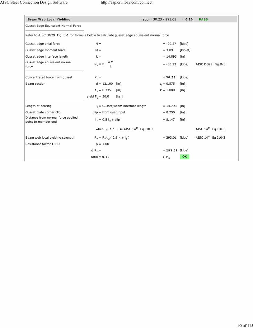
Beam Web Local Yielding ratio = 30.23 / 293.01 = 0.10 PASS
Gusset Edge Equivalent Normal Force
Refer to AISC DG29 Fig. B-1 for formula below to calculate gusset edge equivalent normal force
Gusset edge axial force N = = -20.27 [kips]
Gusset edge moment force M = = 3.09 [kip-ft]
Gusset edge interface length L = = 14.893 [in]
Gusset edge equivalent normalforce
N = N - 4 ML
= -30.23 [kips] AISC DG29 Fig B-1
Concentrated force from gusset P = = 30.23 [kips]
Beam section d = 12.100 [in] t = 0.575 [in]
t = 0.335 [in] k = 1.080 [in]
yield F = 50.0 [ksi]
Length of bearing l = Gusset/Beam interface length = 14.793 [in]
Gusset plate corner clip clip = from user input = 0.750 [in]
Distance from normal force appliedpoint to member end
l = 0.5 l + clip = 8.147 [in]
when l ≤ d , use AISC 14 Eq J10-3 AISC 14 Eq J10-3
Beam web local yielding strength R = F t ( 2.5 k + l ) = 293.01 [kips] AISC 14 Eq J10-3
Resistance factor-LRFD φ = 1.00
φ R = = 293.01 [kips]
ratio = 0.10 > P OK
e
u
f
w
y
b
N b
Nth th
n y w bth
n
u
AISC Steel Connection Design Software http://asp.civilbay.com/connect
90 of 115

Beam to Column End Plate Connection Code=AISC 360-10 LRFD
Result Summary geometries & weld limitations = PASS limit states max ratio = 0.94 PASS
Geometry Restriction Check - End Plate to Column Web PASS
Min Bolt Edge Distance - End Plate to Column Web
Bolt diameter d = = 0.750 [in]
Min edge distance allowed L = = 1.000 [in] AISC 14 Table J3.4
Min edge distance in End Plate toColumn Web
L = = 1.375 [in]
> L OK
Min Bolt Spacing - End Plate to Column Web
Bolt diameter d = = 0.750 [in]
Min bolt spacing allowed L = 2.667 d = 2.000 [in] AISC 14 J3.3
Min Bolt spacing in End Plate toColumn Web
L = = 3.000 [in]
> L OK
Beam Flange Fillet Weld Limitation PASS
Min Fillet Weld Size
Thinner part joined thickness t = = 0.375 [in]
Min fillet weld size allowed w = = 0.188 [in] AISC 14 Table J2.4
Fillet weld size provided w = = 0.375 [in]
> w OK
Min Fillet Weld Length
Fillet weld size provided w = = 0.375 [in]
Min fillet weld length allowed L = 4 x w = 1.500 [in] AISC 14 J2.2b
Min fillet weld length L = 0.5 b - k = 2.437 [in]
> L OK
Beam Web Fillet Weld Limitation PASS
Min Fillet Weld Size
Thinner part joined thickness t = = 0.335 [in]
Min fillet weld size allowed w = = 0.188 [in] AISC 14 Table J2.4
Fillet weld size provided w = = 0.375 [in]
> w OK
Min Fillet Weld Length
Fillet weld size provided w = = 0.375 [in]
Min fillet weld length allowed L = 4 x w = 1.500 [in] AISC 14 J2.2b
Min fillet weld length L = d - 2 k = 9.350 [in]
> L OK
Brace Force Load Case 1 shear V = -35.82 kips axial P = -14.50 kips (T) ratio = 0.41 PASS
b
e-minth
e
e-min
b
s-min bth
s
s-min
minth
min
minth
f 1
min
minth
min
minth
min
AISC Steel Connection Design Software http://asp.civilbay.com/connect
91 of 115

Beam - Shear Yielding - Vy ratio = 35.82 / 121.61 = 0.29 PASS
Section Shear Yielding Check
Sect yield strength F = 50.0 [ksi]
Sect gross area in shear A = = 4.054 [in ]
Shear force required V = = 35.82 [kips]
Sect shear yielding strength R = 0.6 F A = 121.61 [kips] AISC 14 Eq J4-3
Resistance factor-LRFD φ = 1.00 AISC 14 Eq J4-3
φ R = = 121.61 [kips]
ratio = 0.29 > V OK
Beam - Shear Rupture - Vy ratio = 35.82 / 118.56 = 0.30 PASS
Section Shear Rupture Check
Sect tensile strength F = 65.0 [ksi]
Sect net area in shear A = = 4.054 [in ]
Shear force in demand V = = 35.82 [kips]
Sect shear rupture strength R = 0.6 F A = 158.09 [kips] AISC 14 Eq J4-4
Resistance factor-LRFD φ = 0.75 AISC 14 Eq J4-4
φ R = = 118.56 [kips]
ratio = 0.30 > V OK
Beam - Shear Yielding - Vz ratio = 25.00 / 277.73 = 0.09 PASS
Section Shear Yielding Check
Sect yield strength F = 50.0 [ksi]
Sect gross area in shear A = = 9.258 [in ]
Shear force required V = = 25.00 [kips]
Sect shear yielding strength R = 0.6 F A = 277.73 [kips] AISC 14 Eq J4-3
Resistance factor-LRFD φ = 1.00 AISC 14 Eq J4-3
φ R = = 277.73 [kips]
ratio = 0.09 > V OK
Beam - Shear Rupture - Vz ratio = 25.00 / 270.78 = 0.09 PASS
Section Shear Rupture Check
Sect tensile strength F = 65.0 [ksi]
Sect net area in shear A = = 9.258 [in ]
Shear force in demand V = = 25.00 [kips]
Sect shear rupture strength R = 0.6 F A = 361.04 [kips] AISC 14 Eq J4-4
Resistance factor-LRFD φ = 0.75 AISC 14 Eq J4-4
φ R = = 270.78 [kips]
ratio = 0.09 > V OK
y
gv2
u
n y gvth
th
n
u
u
nv2
u
n u nvth
th
n
u
y
gv2
u
n y gvth
th
n
u
u
nv2
u
n u nvth
th
n
u
AISC Steel Connection Design Software http://asp.civilbay.com/connect
92 of 115

Beam - Axial Tensile Yield - Px ratio = 14.50 / 589.50 = 0.02 PASS
Gross area subject to tension A = = 13.100 [in ]
Steel yield strength F = = 50.0 [ksi]
Tensile force required P = = 14.50 [kips]
Tensile yielding strength R = F A = 655.00 [kips] AISC 14 Eq D2-1
Resistance factor-LRFD φ = 0.90 AISC 14 D2 (a)
φ R = = 589.50 [kips] AISC 14 Eq D2-1
ratio = 0.02 > P OK
Beam - Axial Tensile Rupture - Px ratio = 14.50 / 638.63 = 0.02 PASS
Tensile force required P = = 14.50 [kips]
Tensile effective net area A = A U = 13.100 [in ]
Plate tensile strength F = = 65.0 [ksi]
Tensile rupture strength R = F A = 851.50 [kips] AISC 14 Eq D2-2
Resistance factor-LRFD φ = 0.75 AISC 14 D2 (b)
φ R = = 638.63 [kips] AISC 14 Eq D2-2
ratio = 0.02 > P OK
End Plate - Shear Yielding - Vy ratio = 17.91 / 136.13 = 0.13 PASS
Plate Shear Yielding Check
Plate size width b = 12.100 [in] thickness t = 0.375 [in]
Plate yield strength F = 50.0 [ksi]
Plate gross area in shear A = b t = 4.538 [in ]
Shear force required V = = 17.91 [kips]
Plate shear yielding strength R = 0.6 F A = 136.13 [kips] AISC 14 Eq J4-3
Resistance factor-LRFD φ = 1.00 AISC 14 Eq J4-3
φ R = = 136.13 [kips]
ratio = 0.13 > V OK
End Plate - Shear Rupture - Vy ratio = 17.91 / 103.93 = 0.17 PASS
Plate Shear Rupture Check
Bolt hole diameter bolt dia d = ⁄ [in] bolt hole dia d = ⁄ [in] AISC 14 B4.3b
Number of bolt n = 3
Plate size width b = 12.100 [in] thickness t = 0.375 [in]
Plate tensile strength F = 65.0 [ksi]
Plate net area in shear A = ( b - n d ) t = 3.553 [in ]
Shear force required V = = 17.91 [kips]
Plate shear rupture strength R = 0.6 F A = 138.57 [kips] AISC 14 Eq J4-4
Resistance factor-LRFD φ = 0.75 AISC 14 Eq J4-4
φ R = = 103.93 [kips]
ratio = 0.17 > V OK
g2
y
u
n y gth
th
nth
u
u
e n2
u
n u eth
th
nth
u
p p
y
gv p p2
u
n y gvth
th
n
u
b3
4 h7
8th
p p
u
nv p h p2
u
n u nvth
th
n
u
AISC Steel Connection Design Software http://asp.civilbay.com/connect
93 of 115

End Plate - Shear Yielding - Vz ratio = 12.50 / 75.94 = 0.16 PASS
Plate Shear Yielding Check
Plate size width b = 6.750 [in] thickness t = 0.375 [in]
Plate yield strength F = 50.0 [ksi]
Plate gross area in shear A = b t = 2.531 [in ]
Shear force required V = = 12.50 [kips]
Plate shear yielding strength R = 0.6 F A = 75.94 [kips] AISC 14 Eq J4-3
Resistance factor-LRFD φ = 1.00 AISC 14 Eq J4-3
φ R = = 75.94 [kips]
ratio = 0.16 > V OK
End Plate - Shear Rupture - Vz ratio = 12.50 / 54.84 = 0.23 PASS
Plate Shear Rupture Check
Bolt hole diameter bolt dia d = ⁄ [in] bolt hole dia d = ⁄ [in] AISC 14 B4.3b
Number of bolt n = 2
Plate size width b = 6.750 [in] thickness t = 0.375 [in]
Plate tensile strength F = 65.0 [ksi]
Plate net area in shear A = ( b - n d ) t = 1.875 [in ]
Shear force required V = = 12.50 [kips]
Plate shear rupture strength R = 0.6 F A = 73.13 [kips] AISC 14 Eq J4-4
Resistance factor-LRFD φ = 0.75 AISC 14 Eq J4-4
φ R = = 54.84 [kips]
ratio = 0.23 > V OK
p p
y
gv p p2
u
n y gvth
th
n
u
b3
4 h7
8th
p p
u
nv p h p2
u
n u nvth
th
n
u
AISC Steel Connection Design Software http://asp.civilbay.com/connect
94 of 115
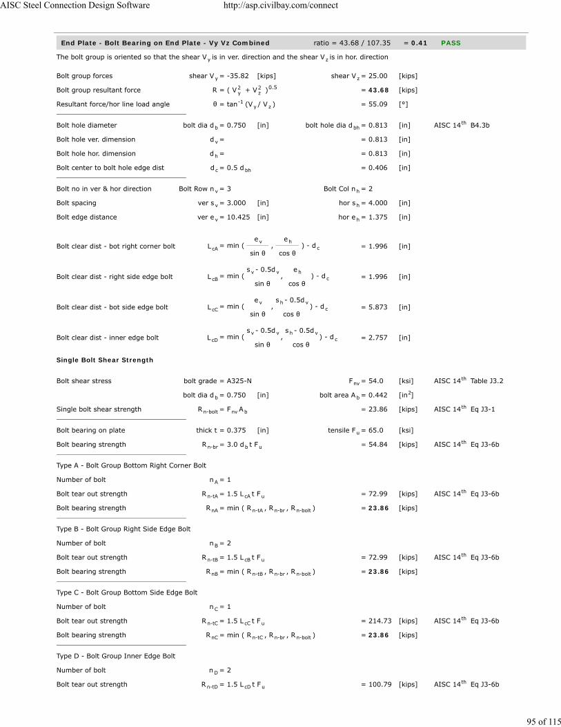
End Plate - Bolt Bearing on End Plate - Vy Vz Combined ratio = 43.68 / 107.35 = 0.41 PASS
The bolt group is oriented so that the shear V is in ver. direction and the shear V is in hor. direction
Bolt group forces shear V = -35.82 [kips] shear V = 25.00 [kips]
Bolt group resultant force R = ( V + V ) = 43.68 [kips]
Resultant force/hor line load angle θ = tan (V / V ) = 55.09 [°]
Bolt hole diameter bolt dia d = 0.750 [in] bolt hole dia d = 0.813 [in] AISC 14 B4.3b
Bolt hole ver. dimension d = = 0.813 [in]
Bolt hole hor. dimension d = = 0.813 [in]
Bolt center to bolt hole edge dist d = 0.5 d = 0.406 [in]
Bolt no in ver & hor direction Bolt Row n = 3 Bolt Col n = 2
Bolt spacing ver s = 3.000 [in] hor s = 4.000 [in]
Bolt edge distance ver e = 10.425 [in] hor e = 1.375 [in]
Bolt clear dist - bot right corner bolt L = min ( e
sin θ ,
e
cos θ ) - d = 1.996 [in]
Bolt clear dist - right side edge bolt L = min ( s - 0.5d
sin θ ,
e
cos θ ) - d = 1.996 [in]
Bolt clear dist - bot side edge bolt L = min ( e
sin θ ,
s - 0.5d
cos θ ) - d = 5.873 [in]
Bolt clear dist - inner edge bolt L = min ( s - 0.5d
sin θ ,
s - 0.5d
cos θ ) - d = 2.757 [in]
Single Bolt Shear Strength
Bolt shear stress bolt grade = A325-N F = 54.0 [ksi] AISC 14 Table J3.2
bolt dia d = 0.750 [in] bolt area A = 0.442 [in ]
Single bolt shear strength R = F A = 23.86 [kips] AISC 14 Eq J3-1
Bolt bearing on plate thick t = 0.375 [in] tensile F = 65.0 [ksi]
Bolt bearing strength R = 3.0 d t F = 54.84 [kips] AISC 14 Eq J3-6b
Type A - Bolt Group Bottom Right Corner Bolt
Number of bolt n = 1
Bolt tear out strength R = 1.5 L t F = 72.99 [kips] AISC 14 Eq J3-6b
Bolt bearing strength R = min ( R , R , R ) = 23.86 [kips]
Type B - Bolt Group Right Side Edge Bolt
Number of bolt n = 2
Bolt tear out strength R = 1.5 L t F = 72.99 [kips] AISC 14 Eq J3-6b
Bolt bearing strength R = min ( R , R , R ) = 23.86 [kips]
Type C - Bolt Group Bottom Side Edge Bolt
Number of bolt n = 1
Bolt tear out strength R = 1.5 L t F = 214.73 [kips] AISC 14 Eq J3-6b
Bolt bearing strength R = min ( R , R , R ) = 23.86 [kips]
Type D - Bolt Group Inner Edge Bolt
Number of bolt n = 2
Bolt tear out strength R = 1.5 L t F = 100.79 [kips] AISC 14 Eq J3-6b
y z
y z
2y
2z
0.5
-1y z
b bhth
v
h
c bh
v h
v h
v h
cAv h
c
cBv v h
c
cCv h v
c
cDv v h v
c
nvth
b b2
n-bolt nv bth
u
n-br b uth
A
n-tA cA uth
nA n-tA n-br n-bolt
B
n-tB cB uth
nB n-tB n-br n-bolt
C
n-tC cC uth
nC n-tC n-br n-bolt
D
n-tD cD uth
AISC Steel Connection Design Software http://asp.civilbay.com/connect
95 of 115

AISC Steel Connection Design Software http://asp.civilbay.com/connect
96 of 115

End Plate - Bolt Bearing on Column Web - Vy Vz Combined ratio = 43.68 / 107.35 = 0.41 PASS
The bolt group is oriented so that the shear V is in ver. direction and the shear V is in hor. direction
Bolt group forces shear V = -35.82 [kips] shear V = 25.00 [kips]
Bolt group resultant force R = ( V + V ) = 43.68 [kips]
Resultant force/hor line load angle θ = tan (V / V ) = 55.09 [°]
Bolt hole diameter bolt dia d = 0.750 [in] bolt hole dia d = 0.813 [in] AISC 14 B4.3b
Bolt hole ver. dimension d = = 0.813 [in]
Bolt hole hor. dimension d = = 0.813 [in]
Bolt center to bolt hole edge dist d = 0.5 d = 0.406 [in]
Bolt no in ver & hor direction Bolt Row n = 3 Bolt Col n = 2
Bolt spacing ver s = 3.000 [in] hor s = 4.000 [in]
Bolt edge distance ver e = 10.425 [in] hor e = 1.375 [in]
Bolt clear dist - bot right corner bolt L = min ( e
sin θ ,
e
cos θ ) - d = 1.996 [in]
Bolt clear dist - right side edge bolt L = min ( s - 0.5d
sin θ ,
e
cos θ ) - d = 1.996 [in]
Bolt clear dist - bot side edge bolt L = min ( e
sin θ ,
s - 0.5d
cos θ ) - d = 5.873 [in]
Bolt clear dist - inner edge bolt L = min ( s - 0.5d
sin θ ,
s - 0.5d
cos θ ) - d = 2.757 [in]
Single Bolt Shear Strength
Bolt shear stress bolt grade = A325-N F = 54.0 [ksi] AISC 14 Table J3.2
bolt dia d = 0.750 [in] bolt area A = 0.442 [in ]
Single bolt shear strength R = F A = 23.86 [kips] AISC 14 Eq J3-1
Bolt bearing on plate thick t = 0.295 [in] tensile F = 65.0 [ksi]
Bolt bearing strength R = 3.0 d t F = 43.14 [kips] AISC 14 Eq J3-6b
Type A - Bolt Group Bottom Right Corner Bolt
Number of bolt n = 1
Bolt tear out strength R = 1.5 L t F = 57.42 [kips] AISC 14 Eq J3-6b
Bolt bearing strength R = min ( R , R , R ) = 23.86 [kips]
Type B - Bolt Group Right Side Edge Bolt
Number of bolt n = 2
Bolt tear out strength R = 1.5 L t F = 57.42 [kips] AISC 14 Eq J3-6b
Bolt bearing strength R = min ( R , R , R ) = 23.86 [kips]
Type C - Bolt Group Bottom Side Edge Bolt
Number of bolt n = 1
Bolt tear out strength R = 1.5 L t F = 168.92 [kips] AISC 14 Eq J3-6b
Bolt bearing strength R = min ( R , R , R ) = 23.86 [kips]
Type D - Bolt Group Inner Edge Bolt
Number of bolt n = 2
Bolt tear out strength R = 1.5 L t F = 79.29 [kips] AISC 14 Eq J3-6b
y z
y z
2y
2z
0.5
-1y z
b bhth
v
h
c bh
v h
v h
v h
cAv h
c
cBv v h
c
cCv h v
c
cDv v h v
c
nvth
b b2
n-bolt nv bth
u
n-br b uth
A
n-tA cA uth
nA n-tA n-br n-bolt
B
n-tB cB uth
nB n-tB n-br n-bolt
C
n-tC cC uth
nC n-tC n-br n-bolt
D
n-tD cD uth
AISC Steel Connection Design Software http://asp.civilbay.com/connect
97 of 115

End Plate - Shear in Vy - Block Shear - Center Strip ratio = 35.82 / 334.30 = 0.11 PASS
Plate Block Shear - Center Strip
Bolt hole diameter bolt dia d = ⁄ [in] bolt hole dia d = ⁄ [in] AISC 14 B4.3b
Plate thickness t = 0.375 [in]
Plate strength F = 50.0 [ksi] F = 65.0 [ksi]
Bolt no in ver & hor dir n = 2 n = 3
Bolt spacing in ver & hor dir s = 4.000 [in] s = 3.000 [in]
Bolt edge dist in ver & hor dir e = 1.375 [in] e = 10.425 [in]
Gross area subject to shear A = [ (n - 1) s + e ] t x 2 = 12.319 [in ]
Net area subject to shear A = A - [(n - 1)+ 0.5] d t x2 = 10.678 [in ]
Net area subject to tension
when sheared out by center strip A = ( n - 1) ( s - d ) t = 1.172 [in ]
Block shear strength required V = = 35.82 [kips]
Uniform tension stress factor U = 1.00 AISC 14 Fig C-J4.2
Bolt shear resistance provided R = min (0.6F A , 0.6F A ) + = 445.73 [kips] AISC 14 Eq J4-5
U F A
Resistance factor-LRFD φ = 0.75 AISC 14 Eq J4-5
φ R = = 334.30 [kips]
ratio = 0.11 > V OK
End Plate - Shear in Vy - Block Shear - 2-Side Strip ratio = 35.82 / 311.45 = 0.12 PASS
Plate Block Shear - 2 Side Strips
Bolt hole diameter bolt dia d = ⁄ [in] bolt hole dia d = ⁄ [in] AISC 14 B4.3b
Plate thickness t = 0.375 [in]
Plate strength F = 50.0 [ksi] F = 65.0 [ksi]
Bolt no in ver & hor dir n = 2 n = 3
Bolt spacing in ver & hor dir s = 4.000 [in] s = 3.000 [in]
Bolt edge dist in ver & hor dir e = 1.375 [in] e = 10.425 [in]
Gross area subject to shear A = [ (n - 1) s + e ] t x 2 = 12.319 [in ]
Net area subject to shear A = A - [(n - 1)+ 0.5] d t x2 = 10.678 [in ]
Net area subject to tension
when sheared out by 2 side strips A = ( e - 0.5 d ) t x 2 = 0.703 [in ]
Block shear strength required V = = 35.82 [kips]
Uniform tension stress factor U = 1.00 AISC 14 Fig C-J4.2
Bolt shear resistance provided R = min (0.6F A , 0.6F A ) + = 415.27 [kips] AISC 14 Eq J4-5
U F A
Resistance factor-LRFD φ = 0.75 AISC 14 Eq J4-5
φ R = = 311.45 [kips]
ratio = 0.12 > V OK
b3
4 h7
8th
p
y u
v h
v h
v h
gv h h h p2
nv gv h h p2
nt v v h p2
u
bsth
n u nv y gvth
bs u ntth
n
u
b3
4 h7
8th
p
y u
v h
v h
v h
gv h h h p2
nv gv h h p2
nt v h p2
u
bsth
n u nv y gvth
bs u ntth
n
u
AISC Steel Connection Design Software http://asp.civilbay.com/connect
98 of 115
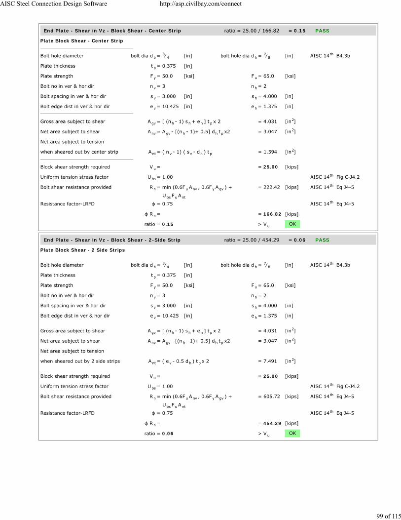
End Plate - Shear in Vz - Block Shear - Center Strip ratio = 25.00 / 166.82 = 0.15 PASS
Plate Block Shear - Center Strip
Bolt hole diameter bolt dia d = ⁄ [in] bolt hole dia d = ⁄ [in] AISC 14 B4.3b
Plate thickness t = 0.375 [in]
Plate strength F = 50.0 [ksi] F = 65.0 [ksi]
Bolt no in ver & hor dir n = 3 n = 2
Bolt spacing in ver & hor dir s = 3.000 [in] s = 4.000 [in]
Bolt edge dist in ver & hor dir e = 10.425 [in] e = 1.375 [in]
Gross area subject to shear A = [ (n - 1) s + e ] t x 2 = 4.031 [in ]
Net area subject to shear A = A - [(n - 1)+ 0.5] d t x2 = 3.047 [in ]
Net area subject to tension
when sheared out by center strip A = ( n - 1) ( s - d ) t = 1.594 [in ]
Block shear strength required V = = 25.00 [kips]
Uniform tension stress factor U = 1.00 AISC 14 Fig C-J4.2
Bolt shear resistance provided R = min (0.6F A , 0.6F A ) + = 222.42 [kips] AISC 14 Eq J4-5
U F A
Resistance factor-LRFD φ = 0.75 AISC 14 Eq J4-5
φ R = = 166.82 [kips]
ratio = 0.15 > V OK
End Plate - Shear in Vz - Block Shear - 2-Side Strip ratio = 25.00 / 454.29 = 0.06 PASS
Plate Block Shear - 2 Side Strips
Bolt hole diameter bolt dia d = ⁄ [in] bolt hole dia d = ⁄ [in] AISC 14 B4.3b
Plate thickness t = 0.375 [in]
Plate strength F = 50.0 [ksi] F = 65.0 [ksi]
Bolt no in ver & hor dir n = 3 n = 2
Bolt spacing in ver & hor dir s = 3.000 [in] s = 4.000 [in]
Bolt edge dist in ver & hor dir e = 10.425 [in] e = 1.375 [in]
Gross area subject to shear A = [ (n - 1) s + e ] t x 2 = 4.031 [in ]
Net area subject to shear A = A - [(n - 1)+ 0.5] d t x2 = 3.047 [in ]
Net area subject to tension
when sheared out by 2 side strips A = ( e - 0.5 d ) t x 2 = 7.491 [in ]
Block shear strength required V = = 25.00 [kips]
Uniform tension stress factor U = 1.00 AISC 14 Fig C-J4.2
Bolt shear resistance provided R = min (0.6F A , 0.6F A ) + = 605.72 [kips] AISC 14 Eq J4-5
U F A
Resistance factor-LRFD φ = 0.75 AISC 14 Eq J4-5
φ R = = 454.29 [kips]
ratio = 0.06 > V OK
b3
4 h7
8th
p
y u
v h
v h
v h
gv h h h p2
nv gv h h p2
nt v v h p2
u
bsth
n u nv y gvth
bs u ntth
n
u
b3
4 h7
8th
p
y u
v h
v h
v h
gv h h h p2
nv gv h h p2
nt v h p2
u
bsth
n u nv y gvth
bs u ntth
n
u
AISC Steel Connection Design Software http://asp.civilbay.com/connect
99 of 115

End Plate / Column Web - Bolt Shear ratio = 43.68 / 107.35 = 0.41 PASS
Bolt group forces shear V = -35.82 [kips] shear V = 25.00 [kips]
Shear resultant force R = ( V + V ) = 43.68 [kips]
Bolt shear stress grade = A325-N F = 54.0 [ksi] AISC 14 Table J3.2
bolt dia d = 0.750 [in] bolt area A = 0.442 [in ]
Number of bolt carried shear n = 6.0 shear plane m = 1
Bolt group eccentricity coefficient C = = 1.000
Required shear strength V = = 43.68 [kips]
Bolt shear strength R = F A n m C = 143.14 [kips] AISC 14 Eq J3-1
Bolt resistance factor-LRFD φ = 0.75 AISC 14 Eq J3-1
φ R = = 107.35 [kips]
ratio = 0.41 > V OK
y z
2y
2z
0.5
nvth
b b2
s
ec
u
n nv b s ecth
th
n
u
AISC Steel Connection Design Software http://asp.civilbay.com/connect
100 of 115

Bolt Tensile Prying Action on End Plate ratio = 2.42 / 7.32 = 0.33 PASS
Bolt group forces shear V = 43.68 [kips] axial P = -14.50 [kips]
Single Bolt Tensile Capacity Without Considering Prying
Bolt grade grade = A325-N
Nominal tensile/shear stress F = 90.0 [ksi] F = 54.0 [ksi] AISC 14 Table J3.2
bolt dia d = 0.750 [in] bolt area A = 0.442 [in ]
Bolt group shear force shear V = 43.68 [kips] no of bolt n = 6
Shear stress required f = V / ( n A ) = 16.48 [ksi]
Resistance factor-LRFD φ = 0.75 AISC 14 J3.7
Modified nominal tensile stress F' = 1.3 F - Fφ F
f ≤ F = 80.38 [ksi] AISC 14 Eq J3-3a
Bolt norminal tensile strength r = F' A = 35.51 [kips] AISC 14 Eq J3-1
Resistance factor-LRFD φ = 0.75 AISC 14 J3.6
Single bolt tensile capacity φ r = = 26.63 [kips]
Single Bolt Tensile Capacity After Considering Prying
End plate width w = 6.750 [in] bolt gage g = 4.000 [in]
web t = 0.335 [in]
Dist from bolt center to plate edge a = 0.5 (w - g) = 1.375 [in]
a' = a + 0.5 d ≤ (1.25 b + 0.5 d ) = 1.750 [in] AISC 14 Eq 9-27
Bolt hole diameter bolt dia d = 0.750 [in] bolt hole dia d = 0.813 [in] AISC 14 B4.3b
Dist from bolt center to face of web b = 0.5(g - t ) = 1.833 [in]
b' = b - 0.5 d = 1.458 [in] AISC 14 Eq 9-21
Bolt pitch spacing s = 3.000
Bolt tributary length p = s p ≤ 2b and p ≤ s = 3.000 [in] AISC 14 Page 9-11
ρ = b' / a' = 0.833 AISC 14 Eq 9-26
δ = 1 - d / p = 0.729 AISC 14 Eq 9-24
Tensile capacity per bolt beforeconsidering prying
B = from calc shown in above section = 26.63 [kips]
Resistance factor-LRFD φ = 0.90 AISC 14 Page 9-10
End plate thickness t = 0.375 [in] tensile F = 65.0 [ksi]
Plate thickness req'd to develop bolttensile capacity without prying
t = ( 4 B b'φ p F
) = 0.941 [in] AISC 14 Eq 9-30a
α' = 1δ (1 + ρ )
[ ( tt
) - 1 ] = 3.959 AISC 14 Eq 9-35
when α' > 1 Q = ( tt
) (1 + δ ) = 0.275 AISC 14 Eq 9-34
Bolt tensile force per bolt in demand T = from calc shown below = 2.42 [kips]
Tensile strength per bolt afterconsidering prying
φ r = B x Q = 7.32 [kips] AISC 14 Eq 9-31
ratio = 0.33 > T OK
Calculate Max Single Bolt Tensile Load
Bolt group force axial P = 14.50 [kips]
Bolt number Bolt Row n = 2 Bolt Col n = 3
Bolt tensile force per bolt T = P / ( n n ) = 2.42 [kips]
nt nvth
b b2
rv b
th
nt ntnt
nvrv nt
th
n nt bth
th
n
w
b bth
b hth
w
bth
v
v vth
th
hth
th
u
cu
0.5 th
c 2 th
c
2 th
nth
h v
v h
AISC Steel Connection Design Software http://asp.civilbay.com/connect
101 of 115

Beam Flange Weld Strength ratio = 2.49 / 16.82 = 0.15 PASS
Assume all axial tensile force P carried by flange weld
Beam section W12X45 b = 8.050 [in] k = 0.938 [in]
Fillet weld length - double fillet L = [b + ( b - 2k )] /2 as dbl fillet = 5.812 [in]
Weld Group Forces
shear V = 12.50 [kips] axial P = -7.25 [kips] in tension
Beam flg-end plate weld length L = = 5.812 [in]
Beam flg-end plate fillet weld size w = = 0.375 [in]
Combined Weld Stress
Weld stress from axial force f = P / L = -1.247 [kip/in] in tension
Weld stress from shear force f = V / L = 2.151 [kip/in]
Weld stress combined - max f = ( f + f ) = 2.486 [kip/in] AISC 14 Eq 8-11
Weld stress load angle θ = tan ( f
f ) = 30.1 [°]
Fillet Weld Strength Calc
Fillet weld leg size w = ⁄ [in] load angle θ = 30.1 [°]
Electrode strength F = 70.0 [ksi] strength coeff C = 1.00 AISC 14 Table 8-3
Number of weld line n = 2 for double fillet
Load angle coefficient C = ( 1 + 0.5 sin θ ) = 1.18 AISC 14 Page 8-9
Fillet weld shear strength R = 0.6 (C x 70 ksi) 0.707 w n C = 26.228 [kip/in] AISC 14 Eq 8-1
Base metal - beam flange thickness t = 0.575 [in] tensile F = 65.0 [ksi]
Base metal - beam flange is in shear, shear rupture as per AISC 14 Eq J4-4 is checked AISC 14 J2.4
Base metal shear rupture R = 0.6 F t = 22.425 [kip/in] AISC 14 Eq J4-4
Double fillet linear shear strength R = min ( R , R ) = 22.425 [kip/in] AISC 14 Eq 9-2
Resistance factor-LRFD φ = 0.75 AISC 14 Eq 8-1
φ R = = 16.819 [kip/in]
ratio = 0.15 > f OK
fb 1b
fb fb 1b
a
v
max2a
2v
0.5 th
-1 a
v
38
EXX 1th
21.5 th
n-w 1 2th
u
th th
n-b uth
n n-w n-bth
th
n
max
AISC Steel Connection Design Software http://asp.civilbay.com/connect
102 of 115

Beam Web Weld Strength ratio = 35.82 / 91.62 = 0.39 PASS
Assume tensile force carried by flange weld and shear force carried by web weld, so there will be no combinedweld tensile/shear stress required
Web weld shear force required V = from gusset interface force calc = 35.82 [kips]
Beam section W12X45 d = 12.100 [in] k = 1.375 [in]
Fillet weld length on beam web L = d - 2 k = 9.350 [in]
Fillet Weld Strength Check
Fillet weld leg size w = ⁄ [in] load angle θ = 0.0 [°]
Electrode strength F = 70.0 [ksi] strength coeff C = 1.00 AISC 14 Table 8-3
Number of weld line n = 2 for double fillet
Load angle coefficient C = ( 1 + 0.5 sin θ ) = 1.00 AISC 14 Page 8-9
Fillet weld shear strength R = 0.6 (C x 70 ksi) 0.707 w n C = 22.271 [kip/in] AISC 14 Eq 8-1
Base metal - beam web thickness t = 0.335 [in] tensile F = 65.0 [ksi]
Base metal - beam web is in shear, shear rupture as per AISC 14 Eq J4-4 is checked AISC 14 J2.4
Base metal shear rupture R = 0.6 F t = 13.065 [kip/in] AISC 14 Eq J4-4
Double fillet linear shear strength R = min ( R , R ) = 13.065 [kip/in] AISC 14 Eq 9-2
Resistance factor-LRFD φ = 0.75 AISC 14 Eq 8-1
φ R = = 9.799 [kip/in]
Shear resistance required V = = 35.82 [kips]
Fillet weld length - double fillet L = = 9.350 [in]
Shear resistance provided φ F = φ R x L = 91.62 [kips]
ratio = 0.39 > V OK
Brace Force Load Case 2 shear V = 85.82 kips axial P = -15.50 kips (T) ratio = 0.94 PASS
Beam - Shear Yielding - Vy ratio = 85.82 / 121.61 = 0.71 PASS
Section Shear Yielding Check
Sect yield strength F = 50.0 [ksi]
Sect gross area in shear A = = 4.054 [in ]
Shear force required V = = 85.82 [kips]
Sect shear yielding strength R = 0.6 F A = 121.61 [kips] AISC 14 Eq J4-3
Resistance factor-LRFD φ = 1.00 AISC 14 Eq J4-3
φ R = = 121.61 [kips]
ratio = 0.71 > V OK
u
b b
b b
38
EXX 1th
21.5 th
n-w 1 2th
u
th th
n-b uth
n n-w n-bth
th
n
u
n n
u
y
gv2
u
n y gvth
th
n
u
AISC Steel Connection Design Software http://asp.civilbay.com/connect
103 of 115

Beam - Shear Rupture - Vy ratio = 85.82 / 118.56 = 0.72 PASS
Section Shear Rupture Check
Sect tensile strength F = 65.0 [ksi]
Sect net area in shear A = = 4.054 [in ]
Shear force in demand V = = 85.82 [kips]
Sect shear rupture strength R = 0.6 F A = 158.09 [kips] AISC 14 Eq J4-4
Resistance factor-LRFD φ = 0.75 AISC 14 Eq J4-4
φ R = = 118.56 [kips]
ratio = 0.72 > V OK
Beam - Shear Yielding - Vz ratio = 25.00 / 277.73 = 0.09 PASS
Section Shear Yielding Check
Sect yield strength F = 50.0 [ksi]
Sect gross area in shear A = = 9.258 [in ]
Shear force required V = = 25.00 [kips]
Sect shear yielding strength R = 0.6 F A = 277.73 [kips] AISC 14 Eq J4-3
Resistance factor-LRFD φ = 1.00 AISC 14 Eq J4-3
φ R = = 277.73 [kips]
ratio = 0.09 > V OK
Beam - Shear Rupture - Vz ratio = 25.00 / 270.78 = 0.09 PASS
Section Shear Rupture Check
Sect tensile strength F = 65.0 [ksi]
Sect net area in shear A = = 9.258 [in ]
Shear force in demand V = = 25.00 [kips]
Sect shear rupture strength R = 0.6 F A = 361.04 [kips] AISC 14 Eq J4-4
Resistance factor-LRFD φ = 0.75 AISC 14 Eq J4-4
φ R = = 270.78 [kips]
ratio = 0.09 > V OK
Beam - Axial Tensile Yield - Px ratio = 15.50 / 589.50 = 0.03 PASS
Gross area subject to tension A = = 13.100 [in ]
Steel yield strength F = = 50.0 [ksi]
Tensile force required P = = 15.50 [kips]
Tensile yielding strength R = F A = 655.00 [kips] AISC 14 Eq D2-1
Resistance factor-LRFD φ = 0.90 AISC 14 D2 (a)
φ R = = 589.50 [kips] AISC 14 Eq D2-1
ratio = 0.03 > P OK
u
nv2
u
n u nvth
th
n
u
y
gv2
u
n y gvth
th
n
u
u
nv2
u
n u nvth
th
n
u
g2
y
u
n y gth
th
nth
u
AISC Steel Connection Design Software http://asp.civilbay.com/connect
104 of 115

Beam - Axial Tensile Rupture - Px ratio = 15.50 / 638.63 = 0.02 PASS
Tensile force required P = = 15.50 [kips]
Tensile effective net area A = A U = 13.100 [in ]
Plate tensile strength F = = 65.0 [ksi]
Tensile rupture strength R = F A = 851.50 [kips] AISC 14 Eq D2-2
Resistance factor-LRFD φ = 0.75 AISC 14 D2 (b)
φ R = = 638.63 [kips] AISC 14 Eq D2-2
ratio = 0.02 > P OK
End Plate - Shear Yielding - Vy ratio = 42.91 / 136.13 = 0.32 PASS
Plate Shear Yielding Check
Plate size width b = 12.100 [in] thickness t = 0.375 [in]
Plate yield strength F = 50.0 [ksi]
Plate gross area in shear A = b t = 4.538 [in ]
Shear force required V = = 42.91 [kips]
Plate shear yielding strength R = 0.6 F A = 136.13 [kips] AISC 14 Eq J4-3
Resistance factor-LRFD φ = 1.00 AISC 14 Eq J4-3
φ R = = 136.13 [kips]
ratio = 0.32 > V OK
End Plate - Shear Rupture - Vy ratio = 42.91 / 103.93 = 0.41 PASS
Plate Shear Rupture Check
Bolt hole diameter bolt dia d = ⁄ [in] bolt hole dia d = ⁄ [in] AISC 14 B4.3b
Number of bolt n = 3
Plate size width b = 12.100 [in] thickness t = 0.375 [in]
Plate tensile strength F = 65.0 [ksi]
Plate net area in shear A = ( b - n d ) t = 3.553 [in ]
Shear force required V = = 42.91 [kips]
Plate shear rupture strength R = 0.6 F A = 138.57 [kips] AISC 14 Eq J4-4
Resistance factor-LRFD φ = 0.75 AISC 14 Eq J4-4
φ R = = 103.93 [kips]
ratio = 0.41 > V OK
End Plate - Shear Yielding - Vz ratio = 12.50 / 75.94 = 0.16 PASS
Plate Shear Yielding Check
Plate size width b = 6.750 [in] thickness t = 0.375 [in]
Plate yield strength F = 50.0 [ksi]
Plate gross area in shear A = b t = 2.531 [in ]
Shear force required V = = 12.50 [kips]
Plate shear yielding strength R = 0.6 F A = 75.94 [kips] AISC 14 Eq J4-3
Resistance factor-LRFD φ = 1.00 AISC 14 Eq J4-3
φ R = = 75.94 [kips]
ratio = 0.16 > V OK
u
e n2
u
n u eth
th
nth
u
p p
y
gv p p2
u
n y gvth
th
n
u
b3
4 h7
8th
p p
u
nv p h p2
u
n u nvth
th
n
u
p p
y
gv p p2
u
n y gvth
th
n
u
AISC Steel Connection Design Software http://asp.civilbay.com/connect
105 of 115

End Plate - Shear Rupture - Vz ratio = 12.50 / 54.84 = 0.23 PASS
Plate Shear Rupture Check
Bolt hole diameter bolt dia d = ⁄ [in] bolt hole dia d = ⁄ [in] AISC 14 B4.3b
Number of bolt n = 2
Plate size width b = 6.750 [in] thickness t = 0.375 [in]
Plate tensile strength F = 65.0 [ksi]
Plate net area in shear A = ( b - n d ) t = 1.875 [in ]
Shear force required V = = 12.50 [kips]
Plate shear rupture strength R = 0.6 F A = 73.13 [kips] AISC 14 Eq J4-4
Resistance factor-LRFD φ = 0.75 AISC 14 Eq J4-4
φ R = = 54.84 [kips]
ratio = 0.23 > V OK
b3
4 h7
8th
p p
u
nv p h p2
u
n u nvth
th
n
u
AISC Steel Connection Design Software http://asp.civilbay.com/connect
106 of 115
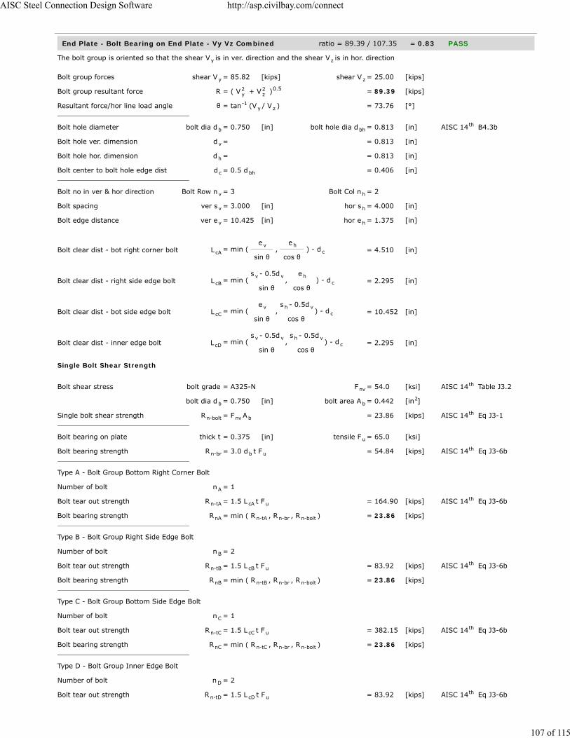
End Plate - Bolt Bearing on End Plate - Vy Vz Combined ratio = 89.39 / 107.35 = 0.83 PASS
The bolt group is oriented so that the shear V is in ver. direction and the shear V is in hor. direction
Bolt group forces shear V = 85.82 [kips] shear V = 25.00 [kips]
Bolt group resultant force R = ( V + V ) = 89.39 [kips]
Resultant force/hor line load angle θ = tan (V / V ) = 73.76 [°]
Bolt hole diameter bolt dia d = 0.750 [in] bolt hole dia d = 0.813 [in] AISC 14 B4.3b
Bolt hole ver. dimension d = = 0.813 [in]
Bolt hole hor. dimension d = = 0.813 [in]
Bolt center to bolt hole edge dist d = 0.5 d = 0.406 [in]
Bolt no in ver & hor direction Bolt Row n = 3 Bolt Col n = 2
Bolt spacing ver s = 3.000 [in] hor s = 4.000 [in]
Bolt edge distance ver e = 10.425 [in] hor e = 1.375 [in]
Bolt clear dist - bot right corner bolt L = min ( e
sin θ ,
e
cos θ ) - d = 4.510 [in]
Bolt clear dist - right side edge bolt L = min ( s - 0.5d
sin θ ,
e
cos θ ) - d = 2.295 [in]
Bolt clear dist - bot side edge bolt L = min ( e
sin θ ,
s - 0.5d
cos θ ) - d = 10.452 [in]
Bolt clear dist - inner edge bolt L = min ( s - 0.5d
sin θ ,
s - 0.5d
cos θ ) - d = 2.295 [in]
Single Bolt Shear Strength
Bolt shear stress bolt grade = A325-N F = 54.0 [ksi] AISC 14 Table J3.2
bolt dia d = 0.750 [in] bolt area A = 0.442 [in ]
Single bolt shear strength R = F A = 23.86 [kips] AISC 14 Eq J3-1
Bolt bearing on plate thick t = 0.375 [in] tensile F = 65.0 [ksi]
Bolt bearing strength R = 3.0 d t F = 54.84 [kips] AISC 14 Eq J3-6b
Type A - Bolt Group Bottom Right Corner Bolt
Number of bolt n = 1
Bolt tear out strength R = 1.5 L t F = 164.90 [kips] AISC 14 Eq J3-6b
Bolt bearing strength R = min ( R , R , R ) = 23.86 [kips]
Type B - Bolt Group Right Side Edge Bolt
Number of bolt n = 2
Bolt tear out strength R = 1.5 L t F = 83.92 [kips] AISC 14 Eq J3-6b
Bolt bearing strength R = min ( R , R , R ) = 23.86 [kips]
Type C - Bolt Group Bottom Side Edge Bolt
Number of bolt n = 1
Bolt tear out strength R = 1.5 L t F = 382.15 [kips] AISC 14 Eq J3-6b
Bolt bearing strength R = min ( R , R , R ) = 23.86 [kips]
Type D - Bolt Group Inner Edge Bolt
Number of bolt n = 2
Bolt tear out strength R = 1.5 L t F = 83.92 [kips] AISC 14 Eq J3-6b
y z
y z
2y
2z
0.5
-1y z
b bhth
v
h
c bh
v h
v h
v h
cAv h
c
cBv v h
c
cCv h v
c
cDv v h v
c
nvth
b b2
n-bolt nv bth
u
n-br b uth
A
n-tA cA uth
nA n-tA n-br n-bolt
B
n-tB cB uth
nB n-tB n-br n-bolt
C
n-tC cC uth
nC n-tC n-br n-bolt
D
n-tD cD uth
AISC Steel Connection Design Software http://asp.civilbay.com/connect
107 of 115

AISC Steel Connection Design Software http://asp.civilbay.com/connect
108 of 115

End Plate - Bolt Bearing on Column Web - Vy Vz Combined ratio = 89.39 / 107.35 = 0.83 PASS
The bolt group is oriented so that the shear V is in ver. direction and the shear V is in hor. direction
Bolt group forces shear V = 85.82 [kips] shear V = 25.00 [kips]
Bolt group resultant force R = ( V + V ) = 89.39 [kips]
Resultant force/hor line load angle θ = tan (V / V ) = 73.76 [°]
Bolt hole diameter bolt dia d = 0.750 [in] bolt hole dia d = 0.813 [in] AISC 14 B4.3b
Bolt hole ver. dimension d = = 0.813 [in]
Bolt hole hor. dimension d = = 0.813 [in]
Bolt center to bolt hole edge dist d = 0.5 d = 0.406 [in]
Bolt no in ver & hor direction Bolt Row n = 3 Bolt Col n = 2
Bolt spacing ver s = 3.000 [in] hor s = 4.000 [in]
Bolt edge distance ver e = 10.425 [in] hor e = 1.375 [in]
Bolt clear dist - bot right corner bolt L = min ( e
sin θ ,
e
cos θ ) - d = 4.510 [in]
Bolt clear dist - right side edge bolt L = min ( s - 0.5d
sin θ ,
e
cos θ ) - d = 2.295 [in]
Bolt clear dist - bot side edge bolt L = min ( e
sin θ ,
s - 0.5d
cos θ ) - d = 10.452 [in]
Bolt clear dist - inner edge bolt L = min ( s - 0.5d
sin θ ,
s - 0.5d
cos θ ) - d = 2.295 [in]
Single Bolt Shear Strength
Bolt shear stress bolt grade = A325-N F = 54.0 [ksi] AISC 14 Table J3.2
bolt dia d = 0.750 [in] bolt area A = 0.442 [in ]
Single bolt shear strength R = F A = 23.86 [kips] AISC 14 Eq J3-1
Bolt bearing on plate thick t = 0.295 [in] tensile F = 65.0 [ksi]
Bolt bearing strength R = 3.0 d t F = 43.14 [kips] AISC 14 Eq J3-6b
Type A - Bolt Group Bottom Right Corner Bolt
Number of bolt n = 1
Bolt tear out strength R = 1.5 L t F = 129.72 [kips] AISC 14 Eq J3-6b
Bolt bearing strength R = min ( R , R , R ) = 23.86 [kips]
Type B - Bolt Group Right Side Edge Bolt
Number of bolt n = 2
Bolt tear out strength R = 1.5 L t F = 66.02 [kips] AISC 14 Eq J3-6b
Bolt bearing strength R = min ( R , R , R ) = 23.86 [kips]
Type C - Bolt Group Bottom Side Edge Bolt
Number of bolt n = 1
Bolt tear out strength R = 1.5 L t F = 300.63 [kips] AISC 14 Eq J3-6b
Bolt bearing strength R = min ( R , R , R ) = 23.86 [kips]
Type D - Bolt Group Inner Edge Bolt
Number of bolt n = 2
Bolt tear out strength R = 1.5 L t F = 66.02 [kips] AISC 14 Eq J3-6b
y z
y z
2y
2z
0.5
-1y z
b bhth
v
h
c bh
v h
v h
v h
cAv h
c
cBv v h
c
cCv h v
c
cDv v h v
c
nvth
b b2
n-bolt nv bth
u
n-br b uth
A
n-tA cA uth
nA n-tA n-br n-bolt
B
n-tB cB uth
nB n-tB n-br n-bolt
C
n-tC cC uth
nC n-tC n-br n-bolt
D
n-tD cD uth
AISC Steel Connection Design Software http://asp.civilbay.com/connect
109 of 115

End Plate - Shear in Vy - Block Shear - Center Strip ratio = 85.82 / 334.30 = 0.26 PASS
Plate Block Shear - Center Strip
Bolt hole diameter bolt dia d = ⁄ [in] bolt hole dia d = ⁄ [in] AISC 14 B4.3b
Plate thickness t = 0.375 [in]
Plate strength F = 50.0 [ksi] F = 65.0 [ksi]
Bolt no in ver & hor dir n = 2 n = 3
Bolt spacing in ver & hor dir s = 4.000 [in] s = 3.000 [in]
Bolt edge dist in ver & hor dir e = 1.375 [in] e = 10.425 [in]
Gross area subject to shear A = [ (n - 1) s + e ] t x 2 = 12.319 [in ]
Net area subject to shear A = A - [(n - 1)+ 0.5] d t x2 = 10.678 [in ]
Net area subject to tension
when sheared out by center strip A = ( n - 1) ( s - d ) t = 1.172 [in ]
Block shear strength required V = = 85.82 [kips]
Uniform tension stress factor U = 1.00 AISC 14 Fig C-J4.2
Bolt shear resistance provided R = min (0.6F A , 0.6F A ) + = 445.73 [kips] AISC 14 Eq J4-5
U F A
Resistance factor-LRFD φ = 0.75 AISC 14 Eq J4-5
φ R = = 334.30 [kips]
ratio = 0.26 > V OK
End Plate - Shear in Vy - Block Shear - 2-Side Strip ratio = 85.82 / 311.45 = 0.28 PASS
Plate Block Shear - 2 Side Strips
Bolt hole diameter bolt dia d = ⁄ [in] bolt hole dia d = ⁄ [in] AISC 14 B4.3b
Plate thickness t = 0.375 [in]
Plate strength F = 50.0 [ksi] F = 65.0 [ksi]
Bolt no in ver & hor dir n = 2 n = 3
Bolt spacing in ver & hor dir s = 4.000 [in] s = 3.000 [in]
Bolt edge dist in ver & hor dir e = 1.375 [in] e = 10.425 [in]
Gross area subject to shear A = [ (n - 1) s + e ] t x 2 = 12.319 [in ]
Net area subject to shear A = A - [(n - 1)+ 0.5] d t x2 = 10.678 [in ]
Net area subject to tension
when sheared out by 2 side strips A = ( e - 0.5 d ) t x 2 = 0.703 [in ]
Block shear strength required V = = 85.82 [kips]
Uniform tension stress factor U = 1.00 AISC 14 Fig C-J4.2
Bolt shear resistance provided R = min (0.6F A , 0.6F A ) + = 415.27 [kips] AISC 14 Eq J4-5
U F A
Resistance factor-LRFD φ = 0.75 AISC 14 Eq J4-5
φ R = = 311.45 [kips]
ratio = 0.28 > V OK
b3
4 h7
8th
p
y u
v h
v h
v h
gv h h h p2
nv gv h h p2
nt v v h p2
u
bsth
n u nv y gvth
bs u ntth
n
u
b3
4 h7
8th
p
y u
v h
v h
v h
gv h h h p2
nv gv h h p2
nt v h p2
u
bsth
n u nv y gvth
bs u ntth
n
u
AISC Steel Connection Design Software http://asp.civilbay.com/connect
110 of 115

End Plate - Shear in Vz - Block Shear - Center Strip ratio = 25.00 / 166.82 = 0.15 PASS
Plate Block Shear - Center Strip
Bolt hole diameter bolt dia d = ⁄ [in] bolt hole dia d = ⁄ [in] AISC 14 B4.3b
Plate thickness t = 0.375 [in]
Plate strength F = 50.0 [ksi] F = 65.0 [ksi]
Bolt no in ver & hor dir n = 3 n = 2
Bolt spacing in ver & hor dir s = 3.000 [in] s = 4.000 [in]
Bolt edge dist in ver & hor dir e = 10.425 [in] e = 1.375 [in]
Gross area subject to shear A = [ (n - 1) s + e ] t x 2 = 4.031 [in ]
Net area subject to shear A = A - [(n - 1)+ 0.5] d t x2 = 3.047 [in ]
Net area subject to tension
when sheared out by center strip A = ( n - 1) ( s - d ) t = 1.594 [in ]
Block shear strength required V = = 25.00 [kips]
Uniform tension stress factor U = 1.00 AISC 14 Fig C-J4.2
Bolt shear resistance provided R = min (0.6F A , 0.6F A ) + = 222.42 [kips] AISC 14 Eq J4-5
U F A
Resistance factor-LRFD φ = 0.75 AISC 14 Eq J4-5
φ R = = 166.82 [kips]
ratio = 0.15 > V OK
End Plate - Shear in Vz - Block Shear - 2-Side Strip ratio = 25.00 / 454.29 = 0.06 PASS
Plate Block Shear - 2 Side Strips
Bolt hole diameter bolt dia d = ⁄ [in] bolt hole dia d = ⁄ [in] AISC 14 B4.3b
Plate thickness t = 0.375 [in]
Plate strength F = 50.0 [ksi] F = 65.0 [ksi]
Bolt no in ver & hor dir n = 3 n = 2
Bolt spacing in ver & hor dir s = 3.000 [in] s = 4.000 [in]
Bolt edge dist in ver & hor dir e = 10.425 [in] e = 1.375 [in]
Gross area subject to shear A = [ (n - 1) s + e ] t x 2 = 4.031 [in ]
Net area subject to shear A = A - [(n - 1)+ 0.5] d t x2 = 3.047 [in ]
Net area subject to tension
when sheared out by 2 side strips A = ( e - 0.5 d ) t x 2 = 7.491 [in ]
Block shear strength required V = = 25.00 [kips]
Uniform tension stress factor U = 1.00 AISC 14 Fig C-J4.2
Bolt shear resistance provided R = min (0.6F A , 0.6F A ) + = 605.72 [kips] AISC 14 Eq J4-5
U F A
Resistance factor-LRFD φ = 0.75 AISC 14 Eq J4-5
φ R = = 454.29 [kips]
ratio = 0.06 > V OK
b3
4 h7
8th
p
y u
v h
v h
v h
gv h h h p2
nv gv h h p2
nt v v h p2
u
bsth
n u nv y gvth
bs u ntth
n
u
b3
4 h7
8th
p
y u
v h
v h
v h
gv h h h p2
nv gv h h p2
nt v h p2
u
bsth
n u nv y gvth
bs u ntth
n
u
AISC Steel Connection Design Software http://asp.civilbay.com/connect
111 of 115

End Plate / Column Web - Bolt Shear ratio = 89.39 / 107.35 = 0.83 PASS
Bolt group forces shear V = 85.82 [kips] shear V = 25.00 [kips]
Shear resultant force R = ( V + V ) = 89.39 [kips]
Bolt shear stress grade = A325-N F = 54.0 [ksi] AISC 14 Table J3.2
bolt dia d = 0.750 [in] bolt area A = 0.442 [in ]
Number of bolt carried shear n = 6.0 shear plane m = 1
Bolt group eccentricity coefficient C = = 1.000
Required shear strength V = = 89.39 [kips]
Bolt shear strength R = F A n m C = 143.14 [kips] AISC 14 Eq J3-1
Bolt resistance factor-LRFD φ = 0.75 AISC 14 Eq J3-1
φ R = = 107.35 [kips]
ratio = 0.83 > V OK
y z
2y
2z
0.5
nvth
b b2
s
ec
u
n nv b s ecth
th
n
u
AISC Steel Connection Design Software http://asp.civilbay.com/connect
112 of 115

Bolt Tensile Prying Action on End Plate ratio = 2.58 / 7.32 = 0.35 PASS
Bolt group forces shear V = 89.39 [kips] axial P = -15.50 [kips]
Single Bolt Tensile Capacity Without Considering Prying
Bolt grade grade = A325-N
Nominal tensile/shear stress F = 90.0 [ksi] F = 54.0 [ksi] AISC 14 Table J3.2
bolt dia d = 0.750 [in] bolt area A = 0.442 [in ]
Bolt group shear force shear V = 89.39 [kips] no of bolt n = 6
Shear stress required f = V / ( n A ) = 33.72 [ksi]
Resistance factor-LRFD φ = 0.75 AISC 14 J3.7
Modified nominal tensile stress F' = 1.3 F - Fφ F
f ≤ F = 42.06 [ksi] AISC 14 Eq J3-3a
Bolt norminal tensile strength r = F' A = 18.58 [kips] AISC 14 Eq J3-1
Resistance factor-LRFD φ = 0.75 AISC 14 J3.6
Single bolt tensile capacity φ r = = 13.94 [kips]
Single Bolt Tensile Capacity After Considering Prying
End plate width w = 6.750 [in] bolt gage g = 4.000 [in]
web t = 0.335 [in]
Dist from bolt center to plate edge a = 0.5 (w - g) = 1.375 [in]
a' = a + 0.5 d ≤ (1.25 b + 0.5 d ) = 1.750 [in] AISC 14 Eq 9-27
Bolt hole diameter bolt dia d = 0.750 [in] bolt hole dia d = 0.813 [in] AISC 14 B4.3b
Dist from bolt center to face of web b = 0.5(g - t ) = 1.833 [in]
b' = b - 0.5 d = 1.458 [in] AISC 14 Eq 9-21
Bolt pitch spacing s = 3.000
Bolt tributary length p = s p ≤ 2b and p ≤ s = 3.000 [in] AISC 14 Page 9-11
ρ = b' / a' = 0.833 AISC 14 Eq 9-26
δ = 1 - d / p = 0.729 AISC 14 Eq 9-24
Tensile capacity per bolt beforeconsidering prying
B = from calc shown in above section = 13.94 [kips]
Resistance factor-LRFD φ = 0.90 AISC 14 Page 9-10
End plate thickness t = 0.375 [in] tensile F = 65.0 [ksi]
Plate thickness req'd to develop bolttensile capacity without prying
t = ( 4 B b'φ p F
) = 0.680 [in] AISC 14 Eq 9-30a
α' = 1δ (1 + ρ )
[ ( tt
) - 1 ] = 1.715 AISC 14 Eq 9-35
when α' > 1 Q = ( tt
) (1 + δ ) = 0.525 AISC 14 Eq 9-34
Bolt tensile force per bolt in demand T = from calc shown below = 2.58 [kips]
Tensile strength per bolt afterconsidering prying
φ r = B x Q = 7.32 [kips] AISC 14 Eq 9-31
ratio = 0.35 > T OK
Calculate Max Single Bolt Tensile Load
Bolt group force axial P = 15.50 [kips]
Bolt number Bolt Row n = 2 Bolt Col n = 3
Bolt tensile force per bolt T = P / ( n n ) = 2.58 [kips]
nt nvth
b b2
rv b
th
nt ntnt
nvrv nt
th
n nt bth
th
n
w
b bth
b hth
w
bth
v
v vth
th
hth
th
u
cu
0.5 th
c 2 th
c
2 th
nth
h v
v h
AISC Steel Connection Design Software http://asp.civilbay.com/connect
113 of 115

Beam Flange Weld Strength ratio = 2.53 / 16.82 = 0.15 PASS
Assume all axial tensile force P carried by flange weld
Beam section W12X45 b = 8.050 [in] k = 0.938 [in]
Fillet weld length - double fillet L = [b + ( b - 2k )] /2 as dbl fillet = 5.812 [in]
Weld Group Forces
shear V = 12.50 [kips] axial P = -7.75 [kips] in tension
Beam flg-end plate weld length L = = 5.812 [in]
Beam flg-end plate fillet weld size w = = 0.375 [in]
Combined Weld Stress
Weld stress from axial force f = P / L = -1.333 [kip/in] in tension
Weld stress from shear force f = V / L = 2.151 [kip/in]
Weld stress combined - max f = ( f + f ) = 2.531 [kip/in] AISC 14 Eq 8-11
Weld stress load angle θ = tan ( f
f ) = 31.8 [°]
Fillet Weld Strength Calc
Fillet weld leg size w = ⁄ [in] load angle θ = 31.8 [°]
Electrode strength F = 70.0 [ksi] strength coeff C = 1.00 AISC 14 Table 8-3
Number of weld line n = 2 for double fillet
Load angle coefficient C = ( 1 + 0.5 sin θ ) = 1.19 AISC 14 Page 8-9
Fillet weld shear strength R = 0.6 (C x 70 ksi) 0.707 w n C = 26.530 [kip/in] AISC 14 Eq 8-1
Base metal - beam flange thickness t = 0.575 [in] tensile F = 65.0 [ksi]
Base metal - beam flange is in shear, shear rupture as per AISC 14 Eq J4-4 is checked AISC 14 J2.4
Base metal shear rupture R = 0.6 F t = 22.425 [kip/in] AISC 14 Eq J4-4
Double fillet linear shear strength R = min ( R , R ) = 22.425 [kip/in] AISC 14 Eq 9-2
Resistance factor-LRFD φ = 0.75 AISC 14 Eq 8-1
φ R = = 16.819 [kip/in]
ratio = 0.15 > f OK
fb 1b
fb fb 1b
a
v
max2a
2v
0.5 th
-1 a
v
38
EXX 1th
21.5 th
n-w 1 2th
u
th th
n-b uth
n n-w n-bth
th
n
max
AISC Steel Connection Design Software http://asp.civilbay.com/connect
114 of 115

Beam Web Weld Strength ratio = 85.82 / 91.62 = 0.94 PASS
Assume tensile force carried by flange weld and shear force carried by web weld, so there will be no combinedweld tensile/shear stress required
Web weld shear force required V = from gusset interface force calc = 85.82 [kips]
Beam section W12X45 d = 12.100 [in] k = 1.375 [in]
Fillet weld length on beam web L = d - 2 k = 9.350 [in]
Fillet Weld Strength Check
Fillet weld leg size w = ⁄ [in] load angle θ = 0.0 [°]
Electrode strength F = 70.0 [ksi] strength coeff C = 1.00 AISC 14 Table 8-3
Number of weld line n = 2 for double fillet
Load angle coefficient C = ( 1 + 0.5 sin θ ) = 1.00 AISC 14 Page 8-9
Fillet weld shear strength R = 0.6 (C x 70 ksi) 0.707 w n C = 22.271 [kip/in] AISC 14 Eq 8-1
Base metal - beam web thickness t = 0.335 [in] tensile F = 65.0 [ksi]
Base metal - beam web is in shear, shear rupture as per AISC 14 Eq J4-4 is checked AISC 14 J2.4
Base metal shear rupture R = 0.6 F t = 13.065 [kip/in] AISC 14 Eq J4-4
Double fillet linear shear strength R = min ( R , R ) = 13.065 [kip/in] AISC 14 Eq 9-2
Resistance factor-LRFD φ = 0.75 AISC 14 Eq 8-1
φ R = = 9.799 [kip/in]
Shear resistance required V = = 85.82 [kips]
Fillet weld length - double fillet L = = 9.350 [in]
Shear resistance provided φ F = φ R x L = 91.62 [kips]
ratio = 0.94 > V OK
u
b b
b b
38
EXX 1th
21.5 th
n-w 1 2th
u
th th
n-b uth
n n-w n-bth
th
n
u
n n
u
AISC Steel Connection Design Software http://asp.civilbay.com/connect
115 of 115