RESUBMITTAL # 3 - #09220 · 2016-03-10 · Structural Loading ASTM E1233 Procedure A Pass. No...
33
Transcript of RESUBMITTAL # 3 - #09220 · 2016-03-10 · Structural Loading ASTM E1233 Procedure A Pass. No...

mibanez
Typewritten Text
mibanez
Typewritten Text
JDF
mibanez
Typewritten Text
03/10/16
mibanez
Typewritten Text
X
mibanez
Typewritten Text
mibanez
Typewritten Text
Submittal #096 - DIV 9 - Stucco Trim Styrofoam Moldings & Outlookers (non-combustible) - RESUBMITTAL # 3 - #09220
mibanez
Typewritten Text
mibanez
Typewritten Text
mibanez
Typewritten Text
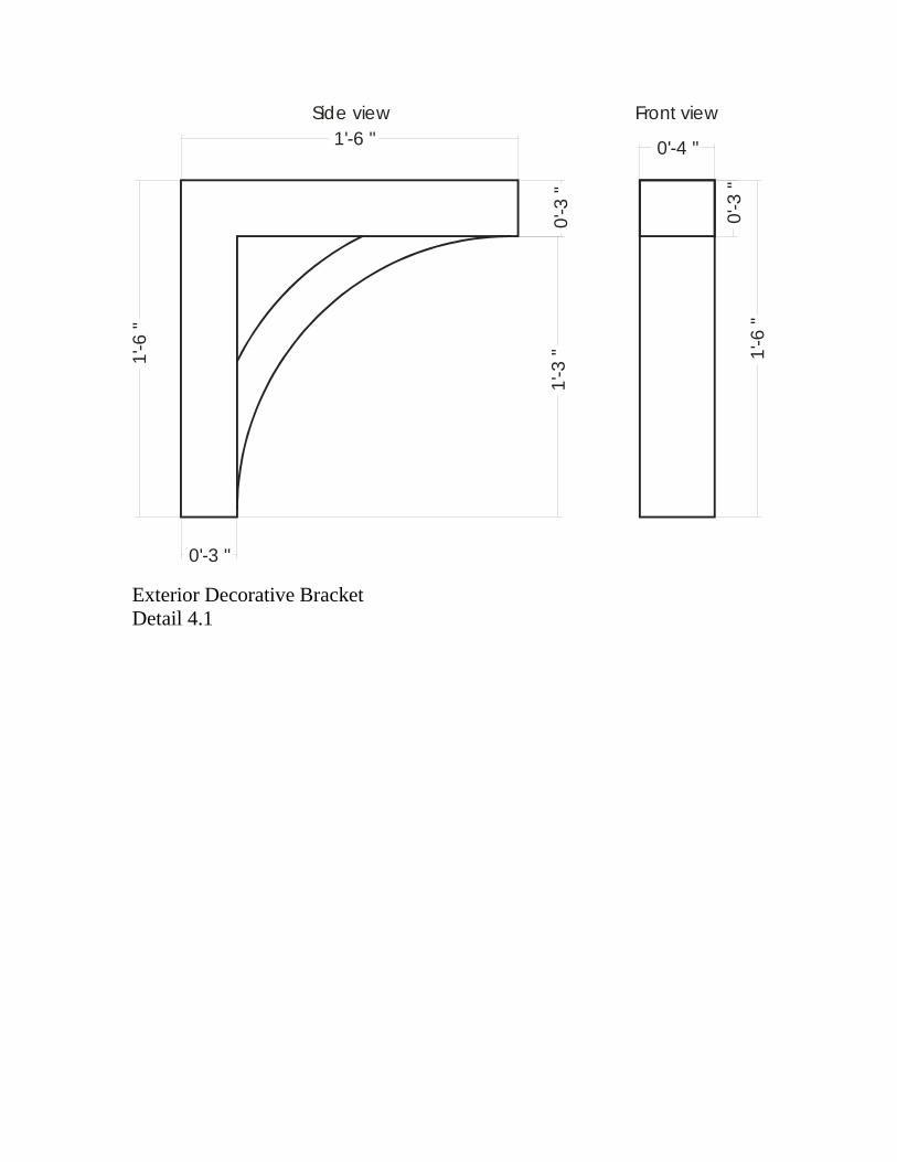
1'-6 "
0'-3 "
1'-6
"
0'-3
"
0'-4 "
0'-3
"1'
-6 "
Side view Front view
1'-3
"
Exterior Decorative Bracket Detail 4.1
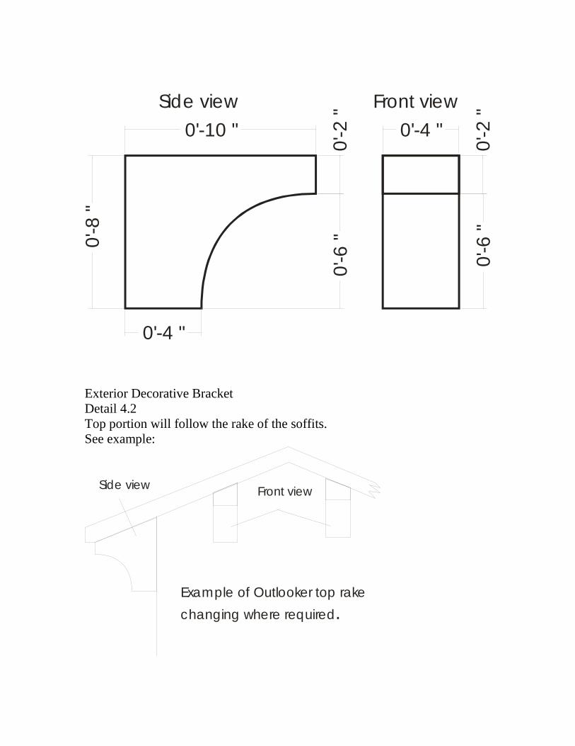
Side view Front view
0'-2
"
0'-10 "
0'-8
"
0'-4 "
0'-2
"0'
-6 "
0'-6
"
0'-4 "
Exterior Decorative Bracket Detail 4.2 Top portion will follow the rake of the soffits. See example:
Example of Outlooker top rake changing where required.
Front view Side view

4'-0 "
0'-6
"
5'-0
"
0'-6 " 2'-10 "
4'-6
"
0'-6 "
0'-6
"4'
-6 "
5'-0
"0'-8 "
0'-6 "
Detail 4.3 as shown on A-3.3

Side view Front view
2'-0 "
2'-0
"
0'-6 "
0'-6
"1'
-6 "
1'-6 "
0'-4 "
0'-6
"1'
-6 "
2'-0
"
Exterior Decorative Brackets Detail 4.4
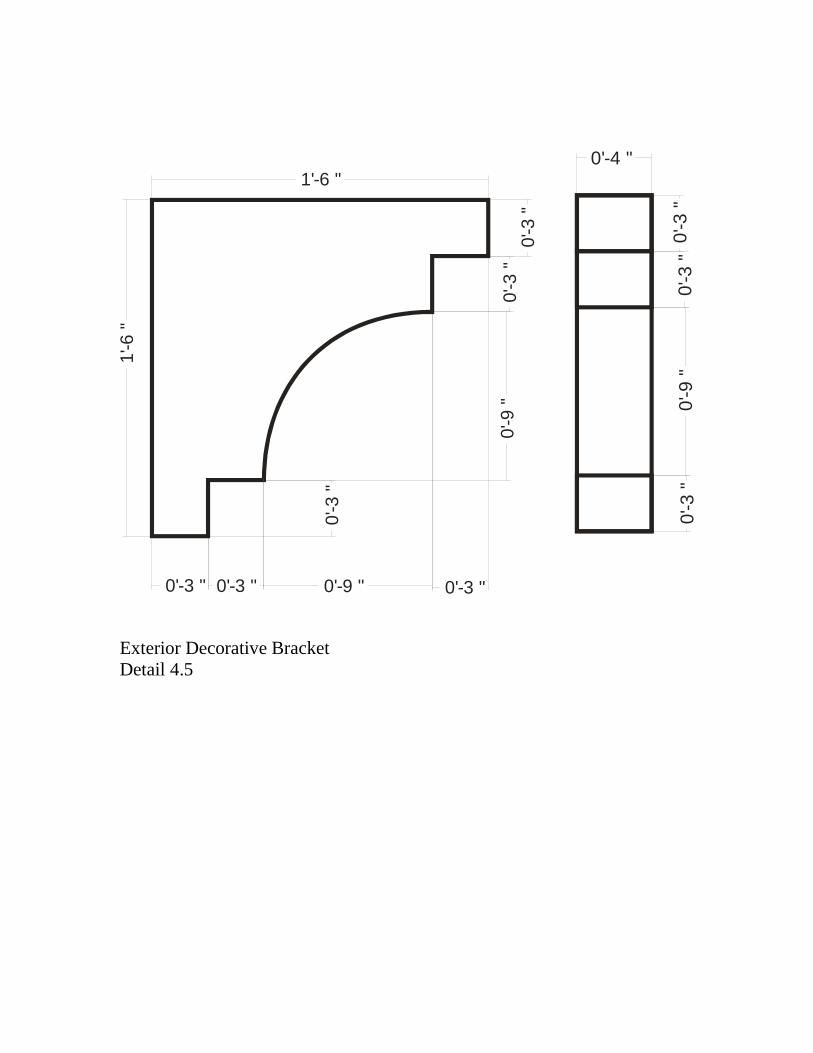
1'-6 "
0'-3
"
1'-6
"
0'-3 " 0'-3 "
0'-3
"
0'-3 "
0'-3
"
0'-9
"
0'-9 "
0'-3
"0'
-3 "
0'-9
"0'
-3 "
0'-4 "
Exterior Decorative Bracket Detail 4.5

0'-4 "1'
-6 "
0'-2 "
1'-0
"0'
-6 “
Exterior Decorative Trim Schedule Detail 1
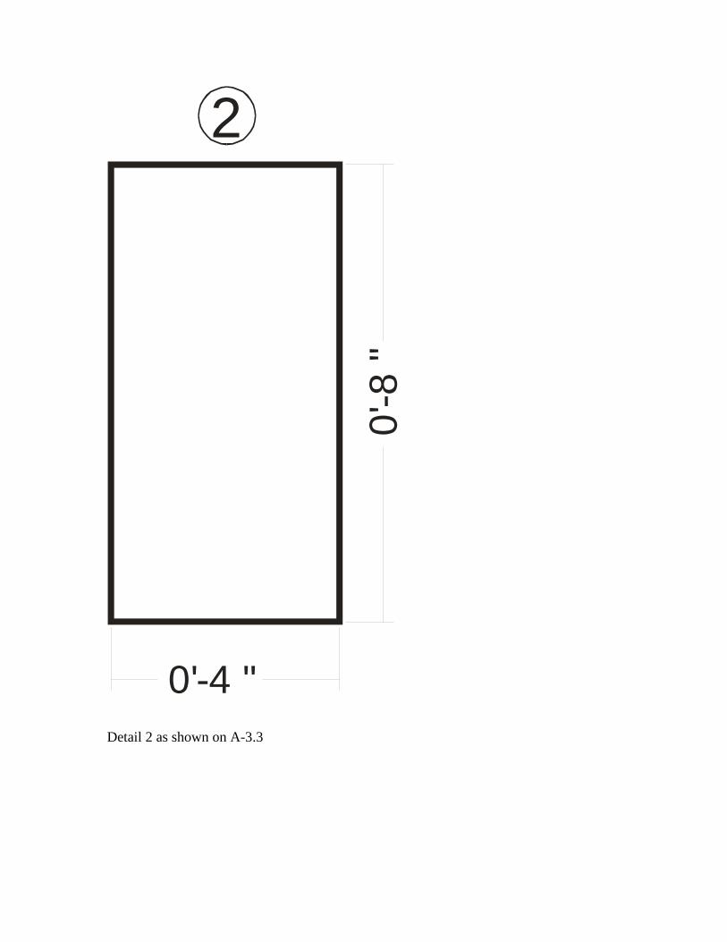
0'-4 "
0'-8
"
2
Detail 2 as shown on A-3.3

0'-6
"1'
-5”
0'-6
"
2'-5
"2'-5 "
0'-6
1/2
"0'
-6 1
/2"
0'-2 "
0'-2 1/2" 0'-1 "
R 10”R 61/2” R 71/2”
0'-1
"0'-1
"
0'-2
"
0'-1
"
Detail 3

0'-4 "
0'-6
"
Detail 4
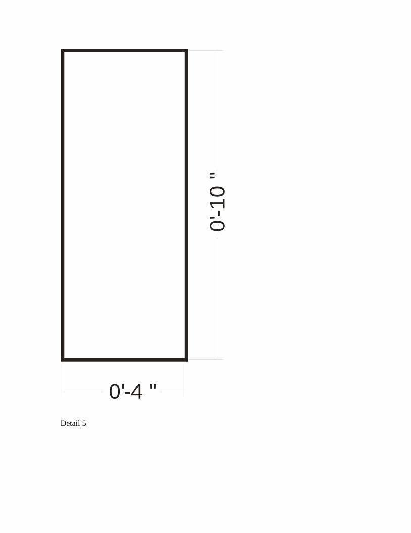
0'-4 "
0'-1
0 "
Detail 5
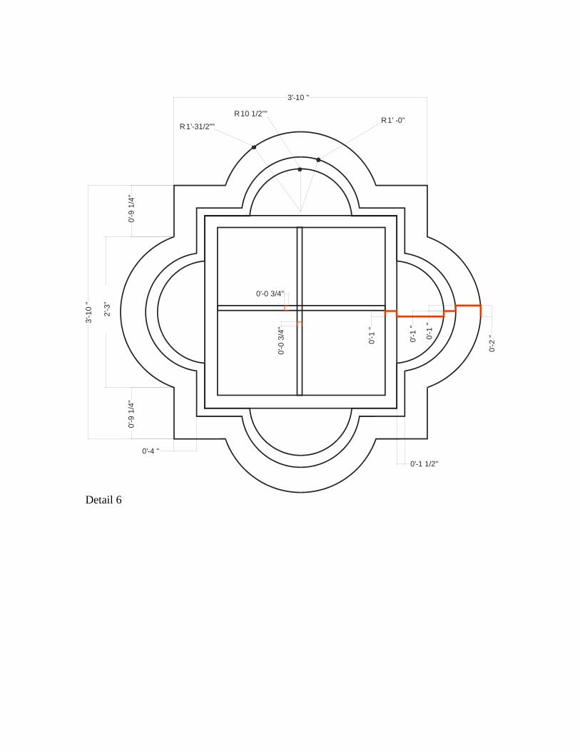
2'-3
”
0'-9
1/4
"0'
-9 1
/4"
3'-1
0 "
3'-10 "
0'-4 "
0'-1 1/2"
R 1’-31/2””
R 10 1/2””R 1’ -0”
0'-1
"
0'-1
"
0'-2
"0'-1
"
0'-0
3/4
"0'-0 3/4"
Detail 6
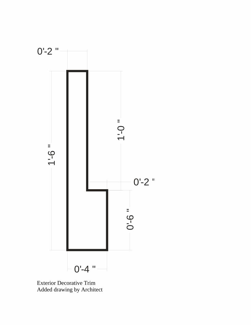
0'-2 "
1'-6
"
0'-4 "
1'-0
"0'
-6 "
0'-2 "
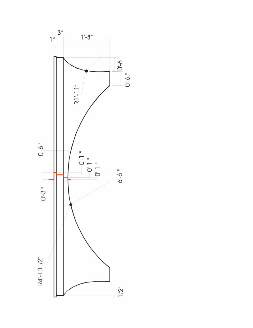
Exterior Decorative Trim Added drawing by Architect
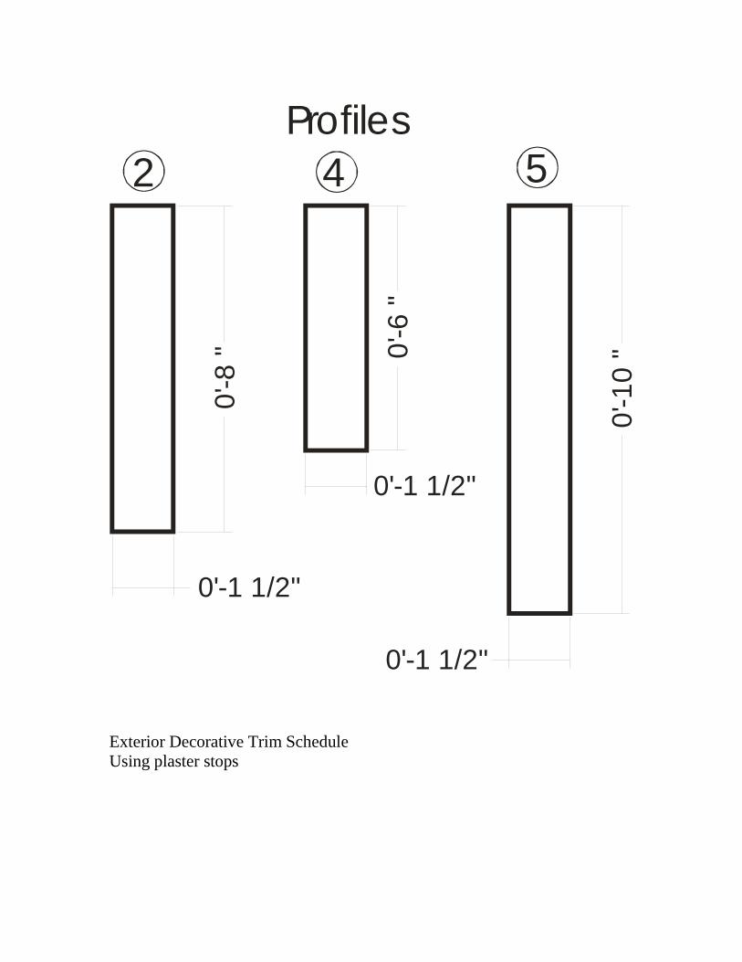
0'-1 1/2"
0'-8
"
0'-1 1/2"
0'-6
"
0'-1 1/2"0'
-10
"
Profiles 2 4 5
Exterior Decorative Trim Schedule Using plaster stops
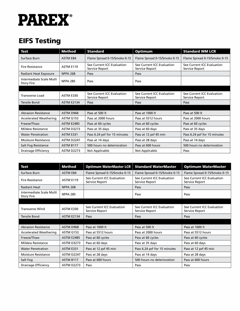
EIFS TestingTest Method Standard Optimum Standard WM LCR
Surface Burn ASTM E84 Flame Spread 0-15/Smoke 0-15 Flame Spread 0-15/Smoke 0-15 Flame Spread 0-15/Smoke 0-15
Fire Resistance ASTM E119See Current ICC Evaluation Service Report
See Current ICC Evaluation Service Report
See Current ICC Evaluation Service Report
Radiant Heat Exposure NFPA 268 Pass Pass
Intermediate Scale Multi Story Fire
NFPA 285 Pass Pass
Transverse Load ASTM E330See Current ICC Evaluation Service Report
See Current ICC Evaluation Service Report
See Current ICC Evaluation Service Report
Tensile Bond ASTM E2134 Pass Pass Pass
Abrasion Resistance ASTM D968 Pass at 500 lt Pass at 1000 lt Pass at 500 lt
Accelerated Weathering ASTM G153 Pass at 2000 hours Pass at 5512 hours Pass at 2000 hours
Freeze/Thaw ASTM E2485 Pass at 60 cycles Pass at 60 cycles Pass at 60 cycles
Mildew Resistance ASTM D3273 Pass at 35 days Pass at 60 days Pass at 35 days
Water Penetration ASTM E331 Pass 6.24 psf for 15 minutes Pass at 12 psf 45 min Pass 6.24 psf for 15 minutes
Moisture Resistance ASTM D2247 Pass at 14 days Pass at 28 days Pass at 14 days
Salt Fog Resistance ASTM B117 500 hours no deterioration Pass at 600 hours 500 hours no deterioration
Drainage Efficiency ASTM D2273 Not Applicable Not Applicable Pass
Test Method Optimum WaterMaster LCR Standard WaterMaster Optimum WaterMaster
Surface Burn ASTM E84 Flame Spread 0-15/Smoke 0-15 Flame Spread 0-15/Smoke 0-15 Flame Spread 0-15/Smoke 0-15
Fire Resistance ASTM E119See Current ICC Evaluation Service Report
See Current ICC Evaluation Service Report
See Current ICC Evaluation Service Report
Radiant Heat NFPA 268 Pass Pass
Intermediate Scale Multi Story Fire
NFPA 285 Pass Pass
Transverse Wind ASTM E330See Current ICC Evaluation Service Report
See Current ICC Evaluation Service Report
See Current ICC Evaluation Service Report
Tensile Bond ASTM E2134 Pass Pass Pass
Abrasion Resistance ASTM D968 Pass at 1000 lt Pass at 500 lt Pass at 1000 lt
Accelerated Weathering ASTM G153 Pass at 5512 hours Pass at 2000 hours Pass at 5512 hours
Freeze/Thaw ASTM E2485 Pass at 60 cycles Pass at 60 cycles Pass at 60 cycles
Mildew Resistance ASTM D3273 Pass at 60 days Pass at 35 days Pass at 60 days
Water Penetration ASTM E331 Pass at 12 psf 45 min Pass 6.24 psf for 15 minutes Pass at 12 psf 45 min
Moisture Resistance ASTM D2247 Pass at 28 days Pass at 14 days Pass at 28 days
Salt Fog ASTM B117 Pass at 600 hours 500 hours no deterioration Pass at 600 hours
Drainage Efficiency ASTM D2273 Pass Pass Pass

Stucco Testing (All Armourwall 100 Assemblies) Test Method Results
Accelerated Weathering ASTM G153 Pass. No cracking, checking, crazing, erosion, or chalking.
ASTM G155 Pass. No cracking, checking, crazing, erosion, or chalking.
Compressive Strength ASTM C109 2538 psi
Flexural Strength ASTM C348 623 psi
Freeze-Thaw ICC AC 11 No cracking, checking or crazing
Transverse Loads ICC AC 11 Refer to ICC-ES ESR 2564
Drainage Efficiency ICC AC 11 Pass. Refer to ICC-ES ESR 2564
Surface Burning Characteristics
ASTM E84Flame Spread: 0 Smoke Developed: 0
Fire Resistance ASTM E119 Pass. Refer to ICC-ES ESR 2564
Combustibility ASTM E136 Pass
Multi-Story Fire Evaluation
UBC 17-6 Pass. Refer to ICC-ES ESR 2564
Radiant Heat Exposure NFPA 268 Pass. Refer to ICC-ES ESR 2564
ACF TestingTest Method Results
Abrasion Resistance ASTM D968 Pass at 1000 lt
Accelerated Weathering ASTM G153 Pass at 5512 hours
Freeze-Thaw ASTM E2485 Pass at 60 cycles
Mildew Resistance ASTM D3273 Pass at 60 days
Water Penetration ASTM E331 Pass at 12 psf 45 min
Moisture Resistance ASTM D2247 Pass at 28 days
Salt Fog ASTM B117 Pass at 600 hours
NOTE: Testing above reflects the usage of Parex Optimum Finishes
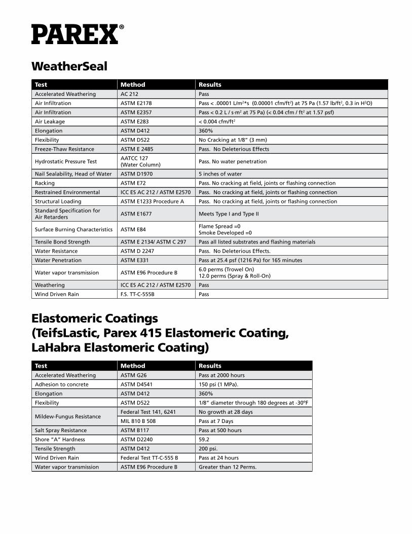
WeatherSealTest Method Results
Accelerated Weathering AC 212 Pass
Air Infiltration ASTM E2178 Pass < .00001 L/m2*s (0.00001 cfm/ft2) at 75 Pa (1.57 lb/ft2, 0.3 in H2O)
Air Infiltration ASTM E2357 Pass < 0.2 L / s·m2 at 75 Pa) (< 0.04 cfm / ft2 at 1.57 psf)
Air Leakage ASTM E283 < 0.004 cfm/ft2
Elongation ASTM D412 360%
Flexibility ASTM D522 No Cracking at 1/8” (3 mm)
Freeze-Thaw Resistance ASTM E 2485 Pass. No Deleterious Effects
Hydrostatic Pressure TestAATCC 127(Water Column)
Pass. No water penetration
Nail Sealability, Head of Water ASTM D1970 5 inches of water
Racking ASTM E72 Pass. No cracking at field, joints or flashing connection
Restrained Environmental ICC ES AC 212 / ASTM E2570 Pass. No cracking at field, joints or flashing connection
Structural Loading ASTM E1233 Procedure A Pass. No cracking at field, joints or flashing connection
Standard Specification for Air Retarders
ASTM E1677 Meets Type I and Type II
Surface Burning Characteristics ASTM E84Flame Spread =0Smoke Developed =0
Tensile Bond Strength ASTM E 2134/ ASTM C 297 Pass all listed substrates and flashing materials
Water Resistance ASTM D 2247 Pass. No Deleterious Effects.
Water Penetration ASTM E331 Pass at 25.4 psf (1216 Pa) for 165 minutes
Water vapor transmission ASTM E96 Procedure B6.0 perms (Trowel On)12.0 perms (Spray & Roll-On)
Weathering ICC ES AC 212 / ASTM E2570 Pass
Wind Driven Rain F.S. TT-C-555B Pass
Elastomeric Coatings (TeifsLastic, Parex 415 Elastomeric Coating, LaHabra Elastomeric Coating) Test Method Results
Accelerated Weathering ASTM G26 Pass at 2000 hours
Adhesion to concrete ASTM D4541 150 psi (1 MPa).
Elongation ASTM D412 360%
Flexibility ASTM D522 1/8” diameter through 180 degrees at -30ºF
Mildew-Fungus ResistanceFederal Test 141, 6241 No growth at 28 days
MIL 810 B 508 Pass at 7 Days
Salt Spray Resistance ASTM B117 Pass at 500 hours
Shore “A” Hardness ASTM D2240 59.2
Tensile Strength ASTM D412 200 psi.
Wind Driven Rain Federal Test TT-C-555 B Pass at 24 hours
Water vapor transmission ASTM E96 Procedure B Greater than 12 Perms.

FacilitiesRedan, GARiverside, CAFrench Camp, CAColorado Springs, COAlbuquerque, NMSan Antonio, TXWilkes Barre, PAFt. Pierce, FL
Corporate OfficeParex USA, Inc.4125 E. La Palma Ave., Suite 250Anaheim, CA 92807(866) 516-0061Tech Support: (800) 226-2424
© Parex USA, Inc. March 2011 • PATDDS
UL Evaluation Report
UL ER7260-01 Issued: March 31, 2015
Visit UL’s On-Line Certifications Directory: www.ul.com/erdirectory for current status of Report. UL Category Code: ULEX CSI MasterFormat® DIVISION: 07 00 00 - THERMAL AND MOISTURE PROTECTION Sub-level 2: 07 20 00 - Thermal Protection Sub-level 3: 07 21 00 - Thermal Insulation Sub-level 4: 07 21 13 - Board Insulation Sub-level 3: 07 22 00 - Roof and Deck Insulation Sub-level 4: 07 22 16 - Roof Board Insulation DIVISION: 31 00 00 - Earthworks Sub-level 3: 31 23 00 - Excavation and Fill Sub-level 4: 31 23 23 - Fill COMPANY: CELLOFOAM NORTH AMERICA INC 1917 ROCKDALE INDUSTRIAL BLVD CONYERS, GA 30012 USA www.cellofoam.comwww.cellofoam.com
Page 2 of 12
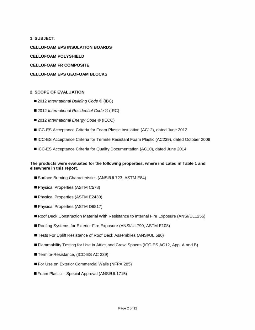
1. SUBJECT:
CELLOFOAM EPS INSULATION BOARDS
CELLOFOAM POLYSHIELD
CELLOFOAM FR COMPOSITE
CELLOFOAM EPS GEOFOAM BLOCKS
2. SCOPE OF EVALUATION
2012 International Building Code ® (IBC) 2012 International Residential Code ® (IRC)
2012 International Energy Code ® (IECC)
ICC-ES Acceptance Criteria for Foam Plastic Insulation (AC12), dated June 2012 ICC-ES Acceptance Criteria for Termite Resistant Foam Plastic (AC239), dated October 2008
ICC-ES Acceptance Criteria for Quality Documentation (AC10), dated June 2014
The products were evaluated for the following properties, where indicated in Table 1 and elsewhere in this report. Surface Burning Characteristics (ANSI/UL723, ASTM E84)
Physical Properties (ASTM C578)
Physical Properties (ASTM E2430)
Physical Properties (ASTM D6817)
Roof Deck Construction Material With Resistance to Internal Fire Exposure (ANSI/UL1256)
Roofing Systems for Exterior Fire Exposure (ANSI/UL790, ASTM E108)
Tests For Uplift Resistance of Roof Deck Assemblies (ANSI/UL 580)
Flammability Testing for Use in Attics and Crawl Spaces (ICC-ES AC12, App. A and B)
Termite-Resistance, (ICC-ES AC 239)
For Use on Exterior Commercial Walls (NFPA 285)
Foam Plastic – Special Approval (ANSI/UL1715)

Page 3 of 12
Table 1 – Properties Evaluated
Properties Evaluated Cellofoam EPS
Cellofoam PolyShield
Cellofoam FR Composite
Cellofoam EPS Geofoam
Surface Burning Characteristics X X
Physical Properties (ASTM C578) X
Physical Properties (ASTM E2430) X
Physical Properties (ASTM D6817) X
Roofing Systems for Exterior Fire Exposure X X X
Roof Deck Construction Materials for Interior Fire Exposure X X
Uplift Tests For Roof Covering Systems X X
Flammability Testing for Use in Attics and Crawl Spaces X X
Termite Resistance* X X X
Foam Plastic - Special Approval X
Exterior Walls (NFPA 285) X X *Products containing the termite resistant additive, Preventol®, are identified as such on the product markings.
Page 4 of 12
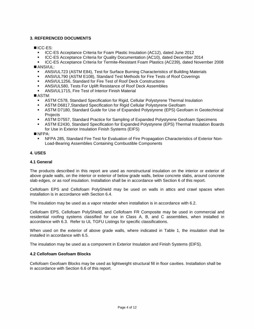
3. REFERENCED DOCUMENTS ICC-ES: ICC-ES Acceptance Criteria for Foam Plastic Insulation (AC12), dated June 2012 ICC-ES Acceptance Criteria for Quality Documentation (AC10), dated December 2014 ICC-ES Acceptance Criteria for Termite-Resistant Foam Plastics (AC239), dated November 2008
ANSI/UL: ANSI/UL723 (ASTM E84), Test for Surface Burning Characteristics of Building Materials ANSI/UL790 (ASTM E108), Standard Test Methods for Fire Tests of Roof Coverings ANSI/UL1256, Standard for Fire Test of Roof Deck Constructions ANSI/UL580, Tests For Uplift Resistance of Roof Deck Assemblies ANSI/UL1715, Fire Test of Interior Finish Material
ASTM: ASTM C578, Standard Specification for Rigid, Cellular Polystyrene Thermal Insulation ASTM D6817,Standard Specification for Rigid Cellular Polystyrene Geofoam ASTM D7180, Standard Guide for Use of Expanded Polystyrene (EPS) Geofoam in Geotechnical
Projects ASTM D7557, Standard Practice for Sampling of Expanded Polystyrene Geofoam Specimens ASTM E2430, Standard Specification for Expanded Polystyrene (EPS) Thermal Insulation Boards
for Use in Exterior Insulation Finish Systems (EIFS) NFPA: NFPA 285, Standard Fire Test for Evaluation of Fire Propagation Characteristics of Exterior Non-
Load-Bearing Assemblies Containing Combustible Components 4. USES
4.1 General
The products described in this report are used as nonstructural insulation on the interior or exterior of above grade walls, on the interior or exterior of below grade walls, below concrete slabs, around concrete slab edges, or as roof insulation. Installation shall be in accordance with Section 6 of this report.
Cellofoam EPS and Cellofoam PolyShield may be used on walls in attics and crawl spaces when installation is in accordance with Section 6.4.
The insulation may be used as a vapor retarder when installation is in accordance with 6.2.
Cellofoam EPS, Cellofoam PolyShield, and Cellofoam FR Composite may be used in commercial and residential roofing systems classified for use in Class A, B, and C assemblies, when installed in accordance with 6.3. Refer to UL TGFU Listings for specific classifications.
When used on the exterior of above grade walls, where indicated in Table 1, the insulation shall be installed in accordance with 6.5.
The insulation may be used as a component in Exterior Insulation and Finish Systems (EIFS).
4.2 Cellofoam Geofoam Blocks Cellofoam Geofoam Blocks may be used as lightweight structural fill in floor cavities. Installation shall be in accordance with Section 6.6 of this report.
Page 5 of 12
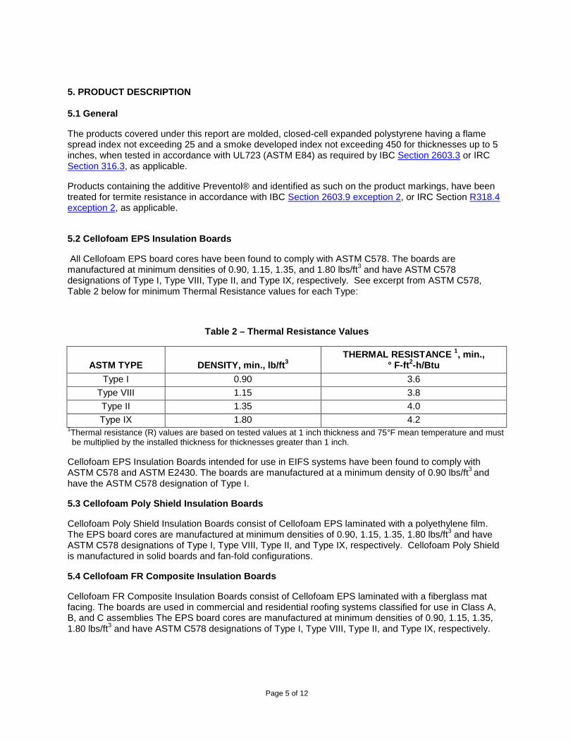
5. PRODUCT DESCRIPTION 5.1 General
The products covered under this report are molded, closed-cell expanded polystyrene having a flame spread index not exceeding 25 and a smoke developed index not exceeding 450 for thicknesses up to 5 inches, when tested in accordance with UL723 (ASTM E84) as required by IBC Section 2603.3 or IRC Section 316.3, as applicable.
Products containing the additive Preventol® and identified as such on the product markings, have been treated for termite resistance in accordance with IBC Section 2603.9 exception 2, or IRC Section R318.4 exception 2, as applicable.
5.2 Cellofoam EPS Insulation Boards
All Cellofoam EPS board cores have been found to comply with ASTM C578. The boards are manufactured at minimum densities of 0.90, 1.15, 1.35, and 1.80 lbs/ft3 and have ASTM C578 designations of Type I, Type VIII, Type II, and Type IX, respectively. See excerpt from ASTM C578, Table 2 below for minimum Thermal Resistance values for each Type:
Table 2 – Thermal Resistance Values
ASTM TYPE
DENSITY, min., lb/ft3
THERMAL RESISTANCE 1, min., ° F-ft2-h/Btu
Type I 0.90 3.6 Type VIII 1.15 3.8 Type II 1.35 4.0 Type IX 1.80 4.2
1Thermal resistance (R) values are based on tested values at 1 inch thickness and 75°F mean temperature and must be multiplied by the installed thickness for thicknesses greater than 1 inch.
Cellofoam EPS Insulation Boards intended for use in EIFS systems have been found to comply with ASTM C578 and ASTM E2430. The boards are manufactured at a minimum density of 0.90 lbs/ft3 and have the ASTM C578 designation of Type I.
5.3 Cellofoam Poly Shield Insulation Boards
Cellofoam Poly Shield Insulation Boards consist of Cellofoam EPS laminated with a polyethylene film. The EPS board cores are manufactured at minimum densities of 0.90, 1.15, 1.35, 1.80 lbs/ft3 and have ASTM C578 designations of Type I, Type VIII, Type II, and Type IX, respectively. Cellofoam Poly Shield is manufactured in solid boards and fan-fold configurations.
5.4 Cellofoam FR Composite Insulation Boards
Cellofoam FR Composite Insulation Boards consist of Cellofoam EPS laminated with a fiberglass mat facing. The boards are used in commercial and residential roofing systems classified for use in Class A, B, and C assemblies The EPS board cores are manufactured at minimum densities of 0.90, 1.15, 1.35, 1.80 lbs/ft3 and have ASTM C578 designations of Type I, Type VIII, Type II, and Type IX, respectively.

Page 6 of 12
5.5 Cellofoam Geofoam Blocks
Cellofoam Geofoam Blocks have been found to comply with ASTM D6817. The blocks are manufactured at minimum densities of 0.90, 1.15, 1.35, and 1.80 lbs/ft3 and have ASTM D6817 designations of EPS15, EPS19, EPS22, and EPS29, respectively. See excerpt from ASTM D6817, Table 3 below.
Table 3 – ASTM D6817 Physical Property Requirements for RCPS Geofoam
ASTM TYPE DENSITY, min., lb/ft3 COMPRESSIVE RESISTANCE, min., psi at 1 % Strain
Type EPS15 0.90 3.6 Type EPS19 1.15 5.8 Type EPS22 1.35 7.3 Type EPS29 1.80 10.9
6. INSTALLATION
6.1 General
The products described in this report are installed in accordance with the manufacturer’s published installation instructions and this evaluation report. The manufacturer’s published installation instructions and this report must be strictly adhered to, and a copy of the instructions shall be available on the jobsite during installation.
These products must be attached to the structure in a manner that will hold the insulation securely in place. The insulation boards must not be used structurally to resist transverse, axial or shear loads.
The interior of the building must be separated from the insulation with a thermal barrier as required by IBC Section 2603.4 or IRC Section 316.4, as applicable.
6.2 For Use as Vapor Retarders
The products described in this report may be used as vapor retarders based on perm values described in Table 4, when required in accordance with the applicable sections of the IBC, IRC and IECC. Vapor retarders are classified as follows:
Class I: 0.1 perm or less Class II: 0.1 <perm ≤ 1.0 perm Class III: 1.0 <perm ≤ 10 perms
Table 4 – Water Vapor Permeance of Cellofoam Insulation Boards
ASTM TYPE DENSITY, min. lb/ft3 MAXIMUM PERMEANCE 1
Type I 0.90 5.0 Type VIII 1.15 3.5 Type II 1.35 3.5 Type IX 1.80 2.5
1Water vapor permeance values are based on 1 inch thickness when tested in accordance with ASTM C578 and ASTM E96. Actual water vapor permeance values may be calculated based on insulation thickness, by dividing the perm value shown by the installed thickness in inches.
Page 7 of 12
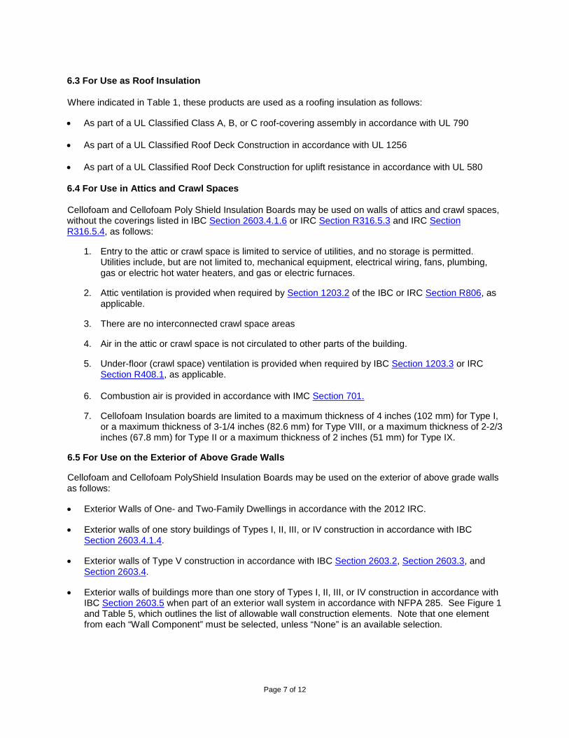
6.3 For Use as Roof Insulation Where indicated in Table 1, these products are used as a roofing insulation as follows:
• As part of a UL Classified Class A, B, or C roof-covering assembly in accordance with UL 790 • As part of a UL Classified Roof Deck Construction in accordance with UL 1256
• As part of a UL Classified Roof Deck Construction for uplift resistance in accordance with UL 580 6.4 For Use in Attics and Crawl Spaces Cellofoam and Cellofoam Poly Shield Insulation Boards may be used on walls of attics and crawl spaces, without the coverings listed in IBC Section 2603.4.1.6 or IRC Section R316.5.3 and IRC Section R316.5.4, as follows:
1. Entry to the attic or crawl space is limited to service of utilities, and no storage is permitted. Utilities include, but are not limited to, mechanical equipment, electrical wiring, fans, plumbing, gas or electric hot water heaters, and gas or electric furnaces.
2. Attic ventilation is provided when required by Section 1203.2 of the IBC or IRC Section R806, as applicable.
3. There are no interconnected crawl space areas
4. Air in the attic or crawl space is not circulated to other parts of the building.
5. Under-floor (crawl space) ventilation is provided when required by IBC Section 1203.3 or IRC Section R408.1, as applicable.
6. Combustion air is provided in accordance with IMC Section 701.
7. Cellofoam Insulation boards are limited to a maximum thickness of 4 inches (102 mm) for Type I, or a maximum thickness of 3-1/4 inches (82.6 mm) for Type VIII, or a maximum thickness of 2-2/3 inches (67.8 mm) for Type II or a maximum thickness of 2 inches (51 mm) for Type IX.
6.5 For Use on the Exterior of Above Grade Walls
Cellofoam and Cellofoam PolyShield Insulation Boards may be used on the exterior of above grade walls as follows:
• Exterior Walls of One- and Two-Family Dwellings in accordance with the 2012 IRC.
• Exterior walls of one story buildings of Types I, II, III, or IV construction in accordance with IBC Section 2603.4.1.4.
• Exterior walls of Type V construction in accordance with IBC Section 2603.2, Section 2603.3, and Section 2603.4.
• Exterior walls of buildings more than one story of Types I, II, III, or IV construction in accordance with IBC Section 2603.5 when part of an exterior wall system in accordance with NFPA 285. See Figure 1 and Table 5, which outlines the list of allowable wall construction elements. Note that one element from each “Wall Component” must be selected, unless “None” is an available selection.
Page 8 of 12
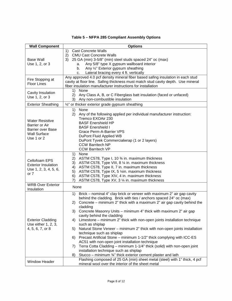
Table 5 – NFPA 285 Compliant Assembly Options
Wall Component Options
Base Wall Use 1, 2, or 3
1) Cast Concrete Walls 2) CMU Cast Concrete Walls 3) 25 GA (min) 3-5/8” (min) steel studs spaced 24” oc (max)
a. Any 5/8” type X gypsum wallboard interior b. Any ½” Exterior gypsum sheathing c. Lateral bracing every 4 ft. vertically
Fire Stopping at Floor Lines
Any approved 4.0 pcf density mineral fiber based safing insulation in each stud cavity at floor line. Safing thickness must match stud cavity depth. Use mineral fiber insulation manufacturer instructions for installation
Cavity Insulation Use 1, 2, or 3
1) None 2) Any Class A, B, or C Fiberglass batt insulation (faced or unfaced) 3) Any non-combustible insulation
Exterior Sheathing ½” or thicker exterior grade gypsum sheathing
Water Resistive Barrier or Air Barrier over Base Wall Surface Use 1 or 2
1) None 2) Any of the following applied per individual manufacturer instruction:
Tremco EXOAir 230 BASF Enershield HP BASF Enershield I Grace Perm-A-Barrier VPS DuPont Fluid Applied WB DuPont Tyvek Commercialwrap (1 or 2 layers) CCW Barritech NP CCW Barritech VP
Cellofoam EPS Exterior Insulation Use 1, 2, 3, 4, 5, 6, or 7
1) None 2) ASTM C578, Type I, 10 ¾ in. maximum thickness 3) ASTM C578, Type VIII, 8 ¼ in. maximum thickness 4) ASTM C578, Type II, 7 in. maximum thickness 5) ASTM C578, Type IX, 5 ¼in. maximum thickness 6) ASTM C578, Type XIV, 4 in. maximum thickness 7) ASTM C578, Type XV, 3 ¼ in. maximum thickness
WRB Over Exterior Insulation None
Exterior Cladding Use either 1, 2, 3, 4, 5, 6, 7, or 8
1) Brick – nominal 4” clay brick or veneer with maximum 2” air gap cavity behind the cladding. Brick with ties / anchors spaced 24” oc (max)
2) Concrete – minimum 2” thick with a maximum 2” air gap cavity behind the cladding
3) Concrete Masonry Units – minimum 4” thick with maximum 2” air gap cavity behind the cladding
4) Limestone – minimum 2” thick with non-open joints installation technique such as shiplap
5) Natural Stone Veneer – minimum 2” thick with non-open joints installation technique such as shiplap
6) Precast Artificial Stone – minimum 1-1/2” thick complying with ICC-ES AC51 with non-open joint installation technique
7) Terra Cotta Cladding – minimum 1-1/4” thick (solid) with non-open joint installation technique such as shiplap
8) Stucco – minimum ¾” thick exterior cement plaster and lath
Window Header Flashing composed of 25 GA (min) sheet metal (steel) with 1” thick, 4 pcf mineral wool over the interior of the sheet metal
Page 9 of 12
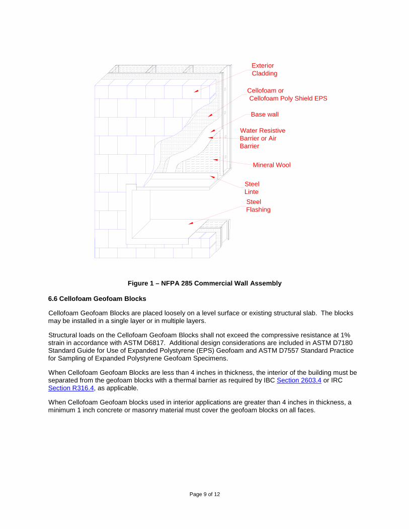
Figure 1 – NFPA 285 Commercial Wall Assembly
6.6 Cellofoam Geofoam Blocks
Cellofoam Geofoam Blocks are placed loosely on a level surface or existing structural slab. The blocks may be installed in a single layer or in multiple layers.
Structural loads on the Cellofoam Geofoam Blocks shall not exceed the compressive resistance at 1% strain in accordance with ASTM D6817. Additional design considerations are included in ASTM D7180 Standard Guide for Use of Expanded Polystyrene (EPS) Geofoam and ASTM D7557 Standard Practice for Sampling of Expanded Polystyrene Geofoam Specimens.
When Cellofoam Geofoam Blocks are less than 4 inches in thickness, the interior of the building must be separated from the geofoam blocks with a thermal barrier as required by IBC Section 2603.4 or IRC Section R316.4, as applicable.
When Cellofoam Geofoam blocks used in interior applications are greater than 4 inches in thickness, a minimum 1 inch concrete or masonry material must cover the geofoam blocks on all faces.
ExteriorCladding
Base wall
Cellofoam or Cellofoam Poly Shield EPS
Mineral Wool
SteelLinteSteelFlashing
Water ResistiveBarrier or AirBarrier

Page 10 of 12
7. CONDITIONS OF USE
7.1 General The products described in this report comply with, or are suitable alternatives to what is specified in the codes listed in Section 2 of this report, subject to the following conditions: the products must be produced, identified, and installed in accordance with the manufacturer’s published installation instructions. If there is a conflict between this report and the manufacturer’s instructions, this report governs. In areas where the probability of termite infestation is defined as “very heavy”, the products described in this report that have not been treated for termite resistance, as described in 5.1 must be installed in accordance with IBC Section 2603.9 or IRC Section R318.4, as applicable. The products described in this report must be separated from the building interior with a thermal barrier, such as ½ in. gypsum board, as required by IBC Section 2603.4 or IRC Section 316.4, as applicable. 7.2 Cellofoam Insulation Products
For a listing of applicable UL Certifications for Cellofoam Insulation Boards, see the Online Certifications Directory for the following categories:
• See UL Online Certifications Directory for Foamed Plastic, UL Classified for Surface Burning Characteristics in accordance with UL723 (BRYX).
• See UL Online Certifications Directory for Polystyrene Thermal Insulation, Rigid Cellular, UL Classified in accordance with ASTM C578 (QORW).
• See UL Online Certifications Directory for Class A, B, or C roof-covering assemblies UL Classified in accordance with UL 790 (TGFU).
• See UL Online Certifications Directory for Roof Deck Constructions for assemblies UL Classified in accordance with UL 1256 and UL 580 (TJBX).
7.3 Cellofoam Geofoam Blocks
Cellofoam Geofoam Blocks less than 4 in. in thickness must be separated from the building interior with a thermal barrier such as ½ in. gypsum board, as required by IBC Section 2603.4 or IRC Section 316.4, as applicable. Cellofoam Geofoam Blocks greater than 4 in. in thickness must be separated from the building interior with a minimum 1 in. thick concrete or masonry on all faces as required by IBC Section 2603.4.1.1.
Design loads to be resisted by the Cellofoam Geofoam Blocks must be determined in accordance with the IBC or IRC, as applicable, and must not exceed the allowable loads noted in this report.
All construction documents specifying the Cellofoam Geofoam Blocks must comply with the design limitations of this report. Design calculations and details for the specific applications must be furnished to the code official to verify compliance with this report and applicable codes. The documents must be prepared by a registered design professional where required by the statutes of the jurisdiction in which the project is to be constructed.

Page 11 of 12
For a listing of applicable UL Certifications for Cellofoam Geofoam Blocks, see the Online Certifications Directory for the following categories:
• See UL Online Certifications Directory for Foamed Plastic, UL Classified for Surface Burning Characteristics in accordance with UL723 (BRYX).
• See UL Online Certifications Directory for Polystyrene Thermal Insulation, Rigid Cellular, UL Classified in accordance with ASTM C578 (QORW).
• See UL Online Certifications Directory for Foamed Plastic, UL Classified for Interior Building Construction in accordance with UL 1715 (OERU).
7.4 Manufacturing Locations: The products are manufactured at the following locations described in Table 6 under the UL LLC Listing or Classification and Follow-Up Service Program, which includes audits in accordance with ICC-ES Acceptance Criteria for Quality Documentation, AC 10.
Table 6 – Cellofoam Manufacturing Locations
LOCATION PLANT ID NO. 1961 Rockdale Industrial Blvd. – Molding
1917 Rockdale Industrial Blvd. – Fabricating P.O. Box 406
Conyers, GA 30012
014X
33 Baron Park Road – Molding Falmouth, VA 22405
008X
11237 Astronaut Blvd. Orlando, FL 32837
013X
150 Crossroads Drive Whiteland, IN 46184
011X
1330 West Redwood Ave. – Molding Sallisaw, OK 74955
012X
8. SUPPORTING EVIDENCE
8.1 Cellofoam Insulation Products
8.1.1 Data in accordance with ICC-ES Acceptance Criteria for Foam Plastic Insulation (AC12), dated June 2012.
8.1.2 Data in accordance with ICC-ES Acceptance Criteria for Termite Resistant Foam Plastics (AC239), dated October 2008.
8.1.3 UL Classification reports in accordance with UL 723, ASTM C578, UL 790, UL 1256, and UL 580. See UL Product Certification Categories (BRYX), (QORW), (TGFU), and (TJBX).
See links to UL’s On-Line Certification Directory in Section 7.2.
8.1.4 Reports and analysis of wall fire tests in accordance with NFPA 285.
8.1.5 Documentation of quality system elements described in AC10, dated December 2014.
Page 12 of 12
8.2 Cellofoam Geofoam Blocks
8.2.1 UL Classification reports in accordance with UL 723, ASTM D6817, and UL 1715. See UL Product Certification Categories (BRYX), (QORW) and (OERU), respectively.
See links to UL’s On-Line Certification Directory for BRYX and QORW in section 7.3.
8.2.2 Data in accordance with ICC-ES Acceptance Criteria for Termite Resistant Foam Plastics (AC239), dated October 2008.
8.2.3 Documentation of quality system elements described in AC10, dated December 2014.
9. IDENTIFICATION
The products described in this evaluation report are identified by a marking bearing the report holder’s name (Cellofoam North America Inc.), the plant identification, the product name, the ASTM type designation, the UL Classification Mark, and the evaluation report number UL ER7260-01. The validity of the evaluation report is contingent upon this identification appearing on the product or UL Classification Mark certificate.
10. USE OF UL EVALUATION REPORT
10.1 The approval of building products, materials or systems is under the responsibility of the applicable authorities having jurisdiction.
10.2 UL Evaluation Reports shall not be used in any manner that implies an endorsement of the product, material or system by UL.
10.3 The current status of this report, as well as a complete directory of UL Evaluation Reports may be found at UL.com via our On-Line Certifications Directory at www.ul.com/erdirectory
© 2015 UL LLC
This UL Evaluation Report is not an endorsement or recommendation for use of the subject and/or product described herein. This report is not the UL Listing or UL Classification Report that covers the subject product. The subject product’s UL Listing or UL Classification is covered under a separate UL Report. UL disclaims all representations and warranties whether express or implied, with respect to this report and the subject or product described herein. Contents of this report may be based on data that has been generated by laboratories other than UL that are accredited as complying with ISO/IEC Standard17025 by the International Accreditation Service (IAS) or by any other accreditation body that is a signatory to the International Laboratory Accreditation Cooperation (ILAC) Mutual Recognition Arrangement (MRA). The scope of the laboratory’s accreditation shall include the specific type of testing covered in the test report. As the accuracy of any non-UL data is the responsibility of the accredited laboratory, UL does not accept responsibility for the accuracy of this data.