· PDF fileSRC-1 RESTRAINTS C D E F G I J K L M SECTION SRC A B SRC N O P CONTENTS SRS AIRBAG...
141
SRC-1 RESTRAINTS C D E F G I J K L M SECTION SRC A B SRC N O P CONTENTS SRS AIRBAG CONTROL SYSTEM BASIC INSPECTION ................................... 5 DIAGNOSIS AND REPAIR WORK FLOW ........ 5 Work Flow ................................................................ 5 FUNCTION DIAGNOSIS .............................. 7 SRS AIR BAG SYSTEM ..................................... 7 System Diagram ....................................................... 7 System Description .................................................. 7 Component Parts Location ....................................... 9 Component Description .......................................... 10 OCCUPANT CLASSIFICATION SYSTEM ........11 System Diagram ..................................................... 11 System Description ................................................ 11 Component Parts Location ..................................... 12 DIAGNOSIS SYSTEM (AIRBAG) .....................13 Diagnosis Description ............................................ 13 Air Bag Warning Lamp Diagnosis .......................... 13 CONSULT-III Function ........................................... 18 COMPONENT DIAGNOSIS ........................ 19 B1001, B1002, B1003, B1004, B1005 DIAG- NOSIS SENSOR UNIT ......................................19 Description ............................................................. 19 DTC Logic .............................................................. 19 Diagnosis Procedure .............................................. 19 B1006, B1007, B1008, B1009, B1010 DIAG- NOSIS SENSOR UNIT ......................................21 Description ............................................................. 21 DTC Logic .............................................................. 21 Diagnosis Procedure .............................................. 21 B1011, B1012, B1013, B1014, B1015 DIAG- NOSIS SENSOR UNIT ......................................23 Description ............................................................. 23 DTC Logic .............................................................. 23 Diagnosis Procedure .............................................. 23 B1017, B1020, B1021 OCCUPANT SENS C/U ... 25 Description ..............................................................25 DTC Logic ...............................................................25 Diagnosis Procedure ..............................................25 B1018 OCCUPANT SENS ................................ 27 Description ..............................................................27 DTC Logic ...............................................................27 Diagnosis Procedure ..............................................27 B1022 OCCUPANT SENS C/U ......................... 29 Description ..............................................................29 DTC Logic ...............................................................29 Diagnosis Procedure ..............................................29 B1023 PASS A/B INDCTR CKT ....................... 31 Description ..............................................................31 DTC Logic ...............................................................31 Diagnosis Procedure ..............................................31 B1026, B1027, B1028, B1029, B1030, B1031 DIAGNOSIS SENSOR UNIT ............................. 33 Description ..............................................................33 DTC Logic ...............................................................33 Diagnosis Procedure ..............................................33 B1033, B1034 CRASH ZONE SEN .................. 35 Description ..............................................................35 DTC Logic ...............................................................35 Diagnosis Procedure ..............................................35 B1035, B1036 CRASH ZONE SEN .................. 37 Description ..............................................................37 DTC Logic ...............................................................37 Diagnosis Procedure ..............................................37 B1042, B1043, B1044, B1045, B1046, B1047 DIAGNOSIS SENSOR UNIT ............................. 39 Description ..............................................................39 DTC Logic ...............................................................39 Diagnosis Procedure ..............................................39 www.gtr-store.eu
Transcript of · PDF fileSRC-1 RESTRAINTS C D E F G I J K L M SECTION SRC A B SRC N O P CONTENTS SRS AIRBAG...

RESTRAINTS
C
D
E
SECTION SRC A
B
SRS AIRBAG CONTROL SYSTEM
F
G
I
J
K
L
M
RC
N
O
P
CONTENTS
S
BASIC INSPECTION .................................... 5
DIAGNOSIS AND REPAIR WORK FLOW ......... 5Work Flow .................................................................5
FUNCTION DIAGNOSIS ............................... 7
SRS AIR BAG SYSTEM ...................................... 7System Diagram ........................................................7System Description ...................................................7Component Parts Location ........................................9Component Description ...........................................10
OCCUPANT CLASSIFICATION SYSTEM .........11System Diagram ......................................................11System Description .................................................11Component Parts Location ......................................12
DIAGNOSIS SYSTEM (AIRBAG) ......................13Diagnosis Description .............................................13Air Bag Warning Lamp Diagnosis ...........................13CONSULT-III Function ............................................18
COMPONENT DIAGNOSIS .........................19
B1001, B1002, B1003, B1004, B1005 DIAG-NOSIS SENSOR UNIT .......................................19
Description ..............................................................19DTC Logic ...............................................................19Diagnosis Procedure ...............................................19
B1006, B1007, B1008, B1009, B1010 DIAG-NOSIS SENSOR UNIT .......................................21
Description ..............................................................21DTC Logic ...............................................................21Diagnosis Procedure ...............................................21
B1011, B1012, B1013, B1014, B1015 DIAG-NOSIS SENSOR UNIT .......................................23
Description ..............................................................23DTC Logic ...............................................................23Diagnosis Procedure ...............................................23
B1017, B1020, B1021 OCCUPANT SENS C/U ...25
Description ...............................................................25DTC Logic ................................................................25Diagnosis Procedure ...............................................25
B1018 OCCUPANT SENS ................................27Description ...............................................................27DTC Logic ................................................................27Diagnosis Procedure ...............................................27
B1022 OCCUPANT SENS C/U .........................29Description ...............................................................29DTC Logic ................................................................29Diagnosis Procedure ...............................................29
B1023 PASS A/B INDCTR CKT .......................31Description ...............................................................31DTC Logic ................................................................31Diagnosis Procedure ...............................................31
B1026, B1027, B1028, B1029, B1030, B1031 DIAGNOSIS SENSOR UNIT .............................33
Description ...............................................................33DTC Logic ................................................................33Diagnosis Procedure ...............................................33
B1033, B1034 CRASH ZONE SEN ..................35Description ...............................................................35DTC Logic ................................................................35Diagnosis Procedure ...............................................35
B1035, B1036 CRASH ZONE SEN ..................37Description ...............................................................37DTC Logic ................................................................37Diagnosis Procedure ...............................................37
B1042, B1043, B1044, B1045, B1046, B1047 DIAGNOSIS SENSOR UNIT .............................39
Description ...............................................................39DTC Logic ................................................................39Diagnosis Procedure ...............................................39
www.gtr-
store
.eu
SRC-1

B1049, B1054 DRIVER AIRBAG MODULE ...... 41Description .............................................................. 41DTC Logic ............................................................... 41Diagnosis Procedure .............................................. 41
B1050, B1055 DRIVER AIRBAG MODULE ...... 43Description .............................................................. 43DTC Logic ............................................................... 43Diagnosis Procedure .............................................. 43
B1051, B1056 DRIVER AIRBAG MODULE ...... 45Description .............................................................. 45DTC Logic ............................................................... 45Diagnosis Procedure .............................................. 45
B1052, B1057 DRIVER AIRBAG MODULE ...... 47Description .............................................................. 47DTC Logic ............................................................... 47Diagnosis Procedure .............................................. 47
B1058, B1059, B1060, B1061, B1062, B1063 DIAGNOSIS SENSOR UNIT .............................. 49
Description .............................................................. 49DTC Logic ............................................................... 49Diagnosis Procedure .............................................. 49
B1065, B1070 ASSIST A/B MODULE .............. 51Description .............................................................. 51DTC Logic ............................................................... 51Diagnosis Procedure .............................................. 51
B1066, B1071 ASSIST A/B MODULE .............. 53Description .............................................................. 53DTC Logic ............................................................... 53Diagnosis Procedure .............................................. 53
B1067, B1072 ASSIST A/B MODULE .............. 55Description .............................................................. 55DTC Logic ............................................................... 55Diagnosis Procedure .............................................. 55
B1068, B1073 ASSIST A/B MODULE .............. 57Description .............................................................. 57DTC Logic ............................................................... 57Diagnosis Procedure .............................................. 57
B1074, B1075, B1076, B1077, B1078, B1079 DIAGNOSIS SENSOR UNIT .............................. 59
Description .............................................................. 59DTC Logic ............................................................... 59Diagnosis Procedure .............................................. 59
B1081 PRE-TEN FRONT RH ............................ 61Description .............................................................. 61DTC Logic ............................................................... 61Diagnosis Procedure .............................................. 61
B1082 PRE-TEN FRONT RH ............................ 63Description .............................................................. 63DTC Logic ............................................................... 63Diagnosis Procedure .............................................. 63
B1083 PRE-TEN FRONT RH ............................ 65Description .............................................................. 65DTC Logic ............................................................... 65Diagnosis Procedure ............................................... 65
B1084 PRE-TEN FRONT RH ............................ 67Description .............................................................. 67DTC Logic ............................................................... 67Diagnosis Procedure ............................................... 67
B1086 PRE-TEN FRONT LH ............................. 69Description .............................................................. 69DTC Logic ............................................................... 69Diagnosis Procedure ............................................... 69
B1087 PRE-TEN FRONT LH ............................. 71Description .............................................................. 71DTC Logic ............................................................... 71Diagnosis Procedure ............................................... 71
B1088 PRE-TEN FRONT LH ............................. 73Description .............................................................. 73DTC Logic ............................................................... 73Diagnosis Procedure ............................................... 73
B1089 PRE-TEN FRONT LH ............................. 75Description .............................................................. 75DTC Logic ............................................................... 75Diagnosis Procedure ............................................... 75
B1106, B1107, B1108, B1109, B1110, B1111 DIAGNOSIS SENSOR UNIT ............................. 77
Description .............................................................. 77DTC Logic ............................................................... 77Diagnosis Procedure ............................................... 77
B1113, B1114 SATELLITE SENS RH .............. 79Description .............................................................. 79DTC Logic ............................................................... 79Diagnosis Procedure ............................................... 79
B1115, B1116 SATELLITE SENS RH .............. 81Description .............................................................. 81DTC Logic ............................................................... 81Diagnosis Procedure ............................................... 81
B1118, B1119 SATELLITE SENS LH ............... 83Description .............................................................. 83DTC Logic ............................................................... 83Diagnosis Procedure ............................................... 83
B1120, B1121 SATELLITE SENS LH ............... 85Description .............................................................. 85DTC Logic ............................................................... 85Diagnosis Procedure ............................................... 85
B1122, B1123, B1124, B1125, B1126, B1127 DIAGNOSIS SENSOR UNIT ............................. 87
Description .............................................................. 87DTC Logic ............................................................... 87Diagnosis Procedure ............................................... 87
www.gtr-
store
.eu
SRC-2
C
D
E
F
G
I
J
K
L
M
A
B
RC
N
O
P
S
B1129 SIDE MODULE RH .................................89Description ..............................................................89DTC Logic ...............................................................89Diagnosis Procedure ...............................................89
B1130 SIDE MODULE RH .................................91Description ..............................................................91DTC Logic ...............................................................91Diagnosis Procedure ...............................................91
B1131 SIDE MODULE RH .................................93Description ..............................................................93DTC Logic ...............................................................93Diagnosis Procedure ...............................................93
B1132 SIDE MODULE RH .................................95Description ..............................................................95DTC Logic ...............................................................95Diagnosis Procedure ...............................................95
B1134 SIDE MODULE LH ..................................97Description ..............................................................97DTC Logic ...............................................................97Diagnosis Procedure ...............................................97
B1135 SIDE MODULE LH ..................................99Description ..............................................................99DTC Logic ...............................................................99Diagnosis Procedure ...............................................99
B1136 SIDE MODULE LH ................................ 101Description ............................................................ 101DTC Logic ............................................................. 101Diagnosis Procedure ............................................. 101
B1137 SIDE MODULE LH ................................ 103Description ............................................................ 103DTC Logic ............................................................. 103Diagnosis Procedure ............................................. 103
B1138, B1139, B1140, B1141, B1142, B1143 DIAGNOSIS SENSOR UNIT ............................ 105
Description ............................................................ 105DTC Logic ............................................................. 105Diagnosis Procedure ............................................. 105
B1145 CURTAIN MODULE RH ....................... 107Description ............................................................ 107DTC Logic ............................................................. 107Diagnosis Procedure ............................................. 107
B1146 CURTAIN MODULE RH ....................... 109Description ............................................................ 109DTC Logic ............................................................. 109Diagnosis Procedure ............................................. 109
B1147 CURTAIN MODULE RH ....................... 111Description ............................................................ 111DTC Logic ............................................................. 111Diagnosis Procedure ............................................. 111
B1148 CURTAIN MODULE RH ...................... 113Description .............................................................113DTC Logic ..............................................................113Diagnosis Procedure .............................................113
B1150 CURTAIN MODULE LH ....................... 115Description .............................................................115DTC Logic ..............................................................115Diagnosis Procedure .............................................115
B1151 CURTAIN MODULE LH ....................... 117Description .............................................................117DTC Logic ..............................................................117Diagnosis Procedure .............................................117
B1152 CURTAIN MODULE LH ....................... 119Description .............................................................119DTC Logic ..............................................................119Diagnosis Procedure .............................................119
B1153 CURTAIN MODULE LH ....................... 121Description .............................................................121DTC Logic ..............................................................121Diagnosis Procedure .............................................121
B1202, B1203, B1204, B1205, B1206, B1207 DIAGNOSIS SENSOR UNIT ........................... 123
Description .............................................................123DTC Logic ..............................................................123Diagnosis Procedure .............................................123
B1209 FRONTAL COLLISION DETECTION .. 125Description .............................................................125DTC Logic ..............................................................125Diagnosis Procedure .............................................125
B1210 SIDE COLLISION DETECTION .......... 127Description .............................................................127DTC Logic ..............................................................127Diagnosis Procedure .............................................127
ECU DIAGNOSIS ....................................... 129
DIAGNOSIS SENSOR UNIT ........................... 129DTC Index .............................................................129Wiring Diagram - SRS AIR BAG CONTROL SYS-TEM - .....................................................................133
SYMPTOM DIAGNOSIS ............................ 139
SRS AIR BAG WARNING LAMP DOES NOT TURN OFF ....................................................... 139
Diagnosis Procedure .............................................139
SRS AIR BAG WARNING LAMP DOES NOT TURN ON ........................................................ 140
Diagnosis Procedure .............................................140
PRECAUTION ............................................ 141
PRECAUTIONS ............................................... 141
www.gtr-
store
.eu
SRC-3
Precaution for Supplemental Restraint System (SRS) "AIR BAG" and "SEAT BELT PRE-TEN-SIONER" ................................................................141
Service .................................................................. 141Occupant Classification System Precaution ......... 141
www.gtr-
store
.eu
SRC-4

DIAGNOSIS AND REPAIR WORK FLOW
C
D
E
F
G
I
J
K
L
M
A
B
RC
N
O
P
< BASIC INSPECTION >
S
BASIC INSPECTIONDIAGNOSIS AND REPAIR WORK FLOWWork Flow INFOID:0000000004031544
OVERALL SEQUENCE
DETAILED FLOW1.GET INFORMATION FOR SYMPTOM
Interview the customer about the symptom.
>> GO TO 2.2.PERFORM PRELIMINARY CHECK
At the beginning of inspection, confirm the condition of power supply circuit, check that the battery is chargedand fuses and fusible links are not blown.Is power supply circuit normal?YES-1 >> GO TO 3. (With CONSULT-III)YES-2 >> GO TO 4. (Without CONSULT-III)NO >> Repair or replace the battery and fuse/fusible links.
JMHIA0027GB
www.gtr-
store
.eu
SRC-5

DIAGNOSIS AND REPAIR WORK FLOW
< BASIC INSPECTION >3.PERFORM SELF-DIAGNOSIS USING “CONSULT-III” (WITH CONSULT-III)
Perform “AIR BAG” Self Diagnostic Result.Is “MALFUNCTIONING PART” displayed on CONSULT-III?YES >> GO TO 5.NO >> Repeat DTC confirmation with diagnostic procedure.
4.PERFORM SELF-DIAGNOSIS “AIR BAG” WARNING LAMP (WITHOUT CONSULT-III)
Check the air bag warning lamp status.Is “MALFUNCTIONING PART” detected?YES >> GO TO 5.NO >> Repeat DTC confirmation with diagnostic procedure.
5.REPAIR OR REPLACE
Repair or replace the malfunctioning part.After the malfunction is repaired, erase the self-diagnostic result. Refer to SRC-13, "Air Bag Warning LampDiagnosis" or SRC-18, "CONSULT-III Function".
>> GO TO 6.6.FINAL CHECK
Perform “AIR BAG” Self Diagnostic Result with CONSULT-III and /or, air bag warning lamp status.Are all malfunctions corrected?YES >> INSPECTION ENDNO-1 >> GO TO 3. (With CONSULT-III)NO-2 >> GO TO 4. (Without CONSULT-III)
www.gtr-
store
.eu
SRC-6

SRS AIR BAG SYSTEM
C
D
E
F
G
I
J
K
L
M
A
B
RC
N
O
P
< FUNCTION DIAGNOSIS >
S
FUNCTION DIAGNOSISSRS AIR BAG SYSTEMSystem Diagram INFOID:0000000004031549
System Description INFOID:0000000004031550
This SRS Air Bag System has the following functions.1. Detects a collision and supplies the energy for deploying air bag and seat belt pre-tensioner.2. Detects electrical malfunction in SRS Air Bag System and Seat Belt Pre-tensioner System, records mal-
function code, and blinking air bag warning lamp.
JMHIA0771GB
www.gtr-
store
.eu
SRC-7

SRS AIR BAG SYSTEM
< FUNCTION DIAGNOSIS >3. Detects and records the deployment of air bag and seat belt pre-tensioner, and turns ON air bag warninglamp.4. Indicates malfunctioning portion with blinking times of air bag warning lamp in diagnosis mode.5. Indicates the malfunction record by CONSULT-III.6. Suppress the deployment of front passenger air bag when front passenger seat is empty or is occupied by
a child or a child-seat.When passenger seat is occupied by a child or a child seat, turns ON front passenger air bag OFF indica-tor.
7. When judges that passenger seat is occupied by a adult or a child and passenger seat belt is not fasten,turns ON seat belt warning lamp.
COLLISION MODE• The operation of supplemental restraint system is different depending on the collision modes applications.
For example, the driver air bag module, front passenger air bag module and front seat belt pre-tensioner areactivated in a frontal collision but not in a side collision.
• SRS configurations that are activated for some collision modes are as per the following.
×: Apply—: Not apply
SRS configuration Frontal collision Left side collision Right side collision
Driver air bag module. Refer to SRC-125 × — —
Front passenger air bag module. Refer to SRC-125 × — —
Front LH seat belt pre-tensioner. Refer to SRC-125 × — —
Front RH seat belt pre-tensioner. Refer to SRC-125 × — —
Front LH side air bag module. Refer to SRC-127 — × —
Front RH side air bag module. Refer to SRC-127 — — ×
LH side curtain air bag module. Refer to SRC-127 — × —
RH side curtain air bag module. Refer to SRC-127 — — ×
www.gtr-
store
.eu
SRC-8

SRS AIR BAG SYSTEM
C
D
E
F
G
I
J
K
L
M
A
B
RC
N
O
P
< FUNCTION DIAGNOSIS >
S
Component Parts Location INFOID:0000000004031551
1. Front passenger air bag module M103
2. Driver air bag module M301, M302 3. Combination switch (Spiral cable) M35
4. LH/RH satellite sensor • LH B23• RH B223
5. Front LH/RH seat belt pre-tensioner• LH B22• RH B222
6. Seat belt buckle switch (Driver side/Passenger side)• Driver side B12 • Passenger side B212
7. Air bag diagnosis sensor unit M147, B37, B 237
8. Front LH/RH side air bag module • LH B11• RH B211
9. Crash zone sensor E36
10. LH/RH side curtain air bag module • LH B32• RH B232
11. Combination meter (air bag warning lamp) M53
12. Front passenger air bag OFF indica-tor M133
13. Occupant Classification System con-trol unit B253
14. Occupant Classification System seat sensor
A. View from vehicle side B. Passenger front seat
JMHIA0772ZZ
www.gtr-
store
.eu
SRC-9

SRS AIR BAG SYSTEM
< FUNCTION DIAGNOSIS >Component Description INFOID:0000000004031552Component Function
Air bag diagnosis sensor unit Detects a collision and supplies power supply for deployment to air bag module and pre-tensioner seat belt.
Air bag module• Driver• Passenger• Front side• Side curtain
Receives signal from air bag diagnosis sensor unit and deploys air bag.
Front seat belt pre-tensioner Receives signal from air bag diagnosis sensor unit and deploys pre-tensioner seat belt.
Seat belt buckle switch Controls deployment timing depending on the seat belt condition that is fastened or unfastened.
Crash zone sensor Transmits signal to air bag diagnosis sensor unit when a frontal collision occurs.
Satellite sensor (LH/RH) Transmits signal to air bag diagnosis sensor unit when a side collision occurs.
Occupant Detection System Detects front passenger seat occupant and judges whether or not deploys front pas-senger seat air bag.
Combination meter (air bag warning lamp) Indicates air bag malfunctioning and deployment by blinking and illuminating air bag warning lamp.
Front passenger air bag OFF indicator Indicates whether or not front passenger air bag is in activation mode subject to the judgement by occupant detection system.
Combination switch (spiral cable) Supplies power supply to driver air bag module on steering wheel.
www.gtr-
store
.eu
SRC-10

OCCUPANT CLASSIFICATION SYSTEM
C
D
E
F
G
I
J
K
L
M
A
B
RC
N
O
P
< FUNCTION DIAGNOSIS >
S
OCCUPANT CLASSIFICATION SYSTEMSystem Diagram INFOID:0000000004032304
OCCUPANT CLASSIFICATION SYSTEM
System Description INFOID:0000000004032305
THIS OCCUPANT CLASSIFICATION SYSTEM HAS THE FOLLOWING FUNCTION.1. Suppress the deployment of front passenger air bag when front passenger seat is empty, or when occu-
pied by child and child-seat. Turns on front passenger air bag OFF indicator when front passenger seat isoccupied by child-seat and child.
2. Indicates malfunction portion with blinking times of air bag warning lamp in diagnosis mode.3. Indicates the malfunctioning record by CONSULT-III.NOTE:Operation of air bag diagnosis sensor unit when air bag diagnosis sensor unit receives information from Occu-pant Classification System
JMHIA0673GB
Status (front passenger seat)
Passenger air bag Front passenger air bag OFF indicator
Air bag warning lamp Seat belt warning lamp (when front passenger seat is unbuckled)
Empty Suppress OFF OFF OFF
Child/ child-seat Suppress ON OFF ON
Adult Enable to deploy OFF OFF ON
Malfunction Suppress ON Blinking OFF
www.gtr-
store
.eu
SRC-11

OCCUPANT CLASSIFICATION SYSTEM
< FUNCTION DIAGNOSIS >Component Parts Location INFOID:00000000040323061. Air bag diagnosis sensor unit B37, B237, M147
2. Occupant Classification System con-trol unit B253
3. Occupant Classification System seat sensor mat
4. Passenger air bag OFF indicator M73
A. View with rear console assembly re-moved
B. Front passenger seat
Component parts Outline of function
Occupant Classification System seat sensor mat Detects if the passenger seat is empty or occupied
Occupant Classification System control unit Transmits the passenger seat status (occupied or empty) to air bag diagnosis sensor unit
Front passenger air bag OFF indicator Turns the front passenger air bag OFF indicator lamp ON when the front passenger seat is occupied by a child or a child-seat
Air bag diagnosis sensor unit Performs the deploy judgement of passenger air bag based on the information from Occu-pant Classification System control unit
JMHIA0773ZZ
www.gtr-
store
.eu
SRC-12
DIAGNOSIS SYSTEM (AIRBAG)
C
D
E
F
G
I
J
K
L
M
A
B
RC
N
O
P
< FUNCTION DIAGNOSIS >
S
DIAGNOSIS SYSTEM (AIRBAG)Diagnosis Description INFOID:0000000004031557
CAUTION:• Never use electrical test equipment on any circuit related to the SRS unless instructed in this Ser-
vice Manual. SRS wiring harnesses can be identified by yellow and/or orange harnesses or harnessconnectors.
• Never repair, splice or modify the SRS wiring harness. If the harness is damaged, replace it with anew one.
• Keep ground portion clean.
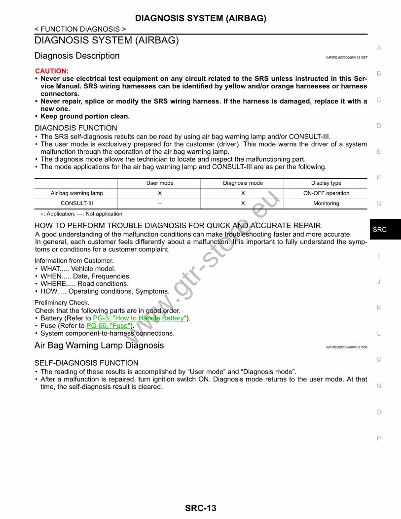
DIAGNOSIS FUNCTION• The SRS self-diagnosis results can be read by using air bag warning lamp and/or CONSULT-III.• The user mode is exclusively prepared for the customer (driver). This mode warns the driver of a system
malfunction through the operation of the air bag warning lamp.• The diagnosis mode allows the technician to locate and inspect the malfunctioning part.• The mode applications for the air bag warning lamp and CONSULT-III are as per the following.
×: Application, —: Not application
HOW TO PERFORM TROUBLE DIAGNOSIS FOR QUICK AND ACCURATE REPAIRA good understanding of the malfunction conditions can make troubleshooting faster and more accurate.In general, each customer feels differently about a malfunction. It is important to fully understand the symp-toms or conditions for a customer complaint.Information from Customer.• WHAT..... Vehicle model.• WHEN..... Date, Frequencies.• WHERE..... Road conditions.• HOW..... Operating conditions, Symptoms.Preliminary Check.Check that the following parts are in good order.• Battery (Refer to PG-3, "How to Handle Battery").• Fuse (Refer to PG-66, "Fuse").• System component-to-harness connections.
Air Bag Warning Lamp Diagnosis INFOID:0000000004031558
SELF-DIAGNOSIS FUNCTION• The reading of these results is accomplished by “User mode” and “Diagnosis mode”.• After a malfunction is repaired, turn ignition switch ON. Diagnosis mode returns to the user mode. At that
time, the self-diagnosis result is cleared.
User mode Diagnosis mode Display type
Air bag warning lamp X X ON-OFF operation
CONSULT-III – X Monitoring
www.gtr-
store
.eu
SRC-13

DIAGNOSIS SYSTEM (AIRBAG)
< FUNCTION DIAGNOSIS >HOW TO CHANGE SELF-DIAGNOSIS MODE WITHOUT CONSULT-IIIDIAGNOSTIC PROCEDURE (USER MODE) Checking air bag operation according to air bag warning lamp-User mode1. Turn the ignition switch from OFF to ON, and check that the air bag warning lamp blinks.2. Compare the air bag warning lamp blinking pattern with the
examples.
PHIA0709E
BF-1845D
www.gtr-
store
.eu
SRC-14

DIAGNOSIS SYSTEM (AIRBAG)
C
D
E
F
G
I
J
K
L
M
A
B
RC
N
O
P
< FUNCTION DIAGNOSIS >
S
Air bag warning lamp examples (User mode)
DIAGNOSTIC PROCEDURE (DIAGNOSIS MODE)1. Turn the ignition switch ON, and check that the air bag warning lamp blinks.2. There are 2 blinking patterns for the air bag warning lamp. One is a 3-second blink followed by a 0.5- sec-
ond blink repeat. The other is two 1.5-second blinks followed by a 0.5-second blink repeat.
Air bag warning lamp operation -User mode SRS condition Reference item
• No malfunction is detected• No further action is necessary —
• The system is malfunctioning and needs to be repaired as indicated
Go to SRC-13, "Diagnosis Descrip-tion"
• Air bag is deployed• Seat belt pre-tensioner is deployed
Go to SRC-125, "Diagnosis Proce-dure" or SRC-127, "Diagnosis Pro-cedure"
• Air bag diagnosis sensor unit is mal-functioning
• Air bag power supply circuit is mal-functioning
• Air bag warning lamp circuit is mal-functioning
Go to SRC-139, "Diagnosis Proce-dure"
• Air bag diagnosis sensor unit is mal-functioning
• Air bag warning lamp circuit is mal-functioning
Go to SRC-140, "Diagnosis Proce-dure"
SHIA0011E
SHIA0012E
SHIA0013E
SHIA0014E
www.gtr-
store
.eu
SRC-15
DIAGNOSIS SYSTEM (AIRBAG)
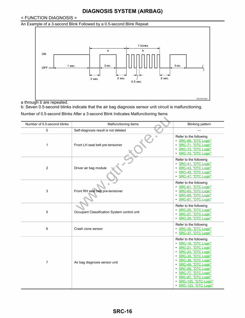
< FUNCTION DIAGNOSIS >An Example of a 3-second Blink Followed by a 0.5-second Blink Repeata through b are repeated.b: Seven 0.5-second blinks indicate that the air bag diagnosis sensor unit circuit is malfunctioning.Number of 0.5-second Blinks After a 3-second Blink Indicates Malfunctioning Items
JMHIA0640GB
Number of 0.5-second blinks Malfunctioning items Blinking pattern
0 Self-diagnosis result is not deleted —
1 Front LH seat belt pre-tensioner
Refer to the following • SRC-69, "DTC Logic"• SRC-71, "DTC Logic"• SRC-73, "DTC Logic"• SRC-75, "DTC Logic"
2 Driver air bag module
Refer to the following • SRC-41, "DTC Logic"• SRC-43, "DTC Logic"• SRC-45, "DTC Logic"• SRC-47, "DTC Logic"
3 Front RH seat belt pre-tensioner
Refer to the following • SRC-61, "DTC Logic"• SRC-63, "DTC Logic"• SRC-65, "DTC Logic"• SRC-67, "DTC Logic"
5 Occupant Classification System control unit
Refer to the following • SRC-25, "DTC Logic"• SRC-27, "DTC Logic"• SRC-29, "DTC Logic"
6 Crash zone sensorRefer to the following • SRC-35, "DTC Logic"• SRC-37, "DTC Logic"
7 Air bag diagnosis sensor unit
Refer to the following • SRC-19, "DTC Logic"• SRC-21, "DTC Logic"• SRC-23, "DTC Logic"• SRC-33, "DTC Logic"• SRC-39, "DTC Logic"• SRC-49, "DTC Logic"• SRC-59, "DTC Logic"• SRC-77, "DTC Logic"• SRC-87, "DTC Logic"• SRC-105, "DTC Logic"• SRC-123, "DTC Logic"
www.gtr-
store
.eu
SRC-16

DIAGNOSIS SYSTEM (AIRBAG)
C
D
E
F
G
I
J
K
L
M
A
B
RC
N
O
P
< FUNCTION DIAGNOSIS >
S
An Example of Two 1.5-second Blinks Followed by a 0.5-second Blink Repeat
a through b are repeated.b: Six 0.5-second blinks indicate that the LH side curtain air bag module circuit is malfunctioning.Number of 0.5-second Blinks After Two 1.5-second Blinks Indicates Malfunctioning Items
HOW TO ERASE SELF-DIAGNOSTIC RESULTSAfter a malfunction is repaired, turn the ignition switch OFF for at least one second, then turn ignition switchON. Diagnosis mode returns to the user mode. At that time the self-diagnosis result is cleared.
8 Front passenger air bag module
Refer to the following • SRC-51, "DTC Logic"• SRC-53, "DTC Logic"• SRC-55, "DTC Logic"• SRC-57, "DTC Logic"
11 Front passenger air bag OFF indicator Refer to SRC-31, "DTC Logic".
Number of 0.5-second blinks Malfunctioning items Blinking pattern
JMHIA0641GB
Number of 0.5-second blinks Malfunctioning items B linking pattern
1 Front RH side air bag module
Refer to the following • SRC-89, "DTC Logic"• SRC-91, "DTC Logic"• SRC-93, "DTC Logic"• SRC-95, "DTC Logic"
2 Front LH side air bag module
Refer to the following • SRC-97, "DTC Logic"• SRC-99, "DTC Logic"• SRC-101, "DTC Logic"• SRC-103, "DTC Logic"
3 RH satellite sensorRefer to the following • SRC-79, "DTC Logic"• SRC-81, "DTC Logic"
4 LH satellite sensorRefer to the following • SRC-83, "DTC Logic"• SRC-85, "DTC Logic"
5 RH side curtain air bag module
Refer to the following • SRC-107, "DTC Logic"• SRC-109, "DTC Logic"• SRC-111, "DTC Logic"• SRC-113, "DTC Logic"
6 LH side curtain air bag module
Refer to the following • SRC-115, "DTC Logic"• SRC-117, "DTC Logic"• SRC-119, "DTC Logic"• SRC-121, "DTC Logic"
www.gtr-
store
.eu
SRC-17
DIAGNOSIS SYSTEM (AIRBAG)
< FUNCTION DIAGNOSIS >CONSULT-III Function INFOID:0000000004031559HOW TO CHANGE SELF-DIAGNOSIS MODE WITH CONSULT-IIIFrom User Mode to Diagnosis ModeAfter selecting “AIR BAG” on the “SELECT SYSTEM” screen, User mode automatically changes to Diagnosismode.From Diagnosis Mode to User ModeTo return to User mode from Diagnosis mode, touch the “BACK” key of CONSULT-III until “SELECT SYSTEM”appears, then diagnosis mode automatically changes to User mode.
DIAGNOSIS MODE FOR CONSULT-III• “SELF-DIAG [CURRENT]”
The current self-diagnosis results (also indicated with the number of air bag warning lamp blinks in diagnosismode) are displayed on CONSULT-III screen in real time. This refers to a malfunctioning part requiringrepairs.
• “SELF-DIAG [PAST]”Diagnosis results previously stored in the memory are displayed on CONSULT-III screen. The stored resultsare not erased until memory erasing is executed.
• “TROUBLE DIAG RECORD”With TROUBLE DIAG RECORD, diagnosis results previously erased by a reset operation can be displayedon CONSULT-III screen.
• “DISCRIMINATED NO.”The air bag diagnosis sensor unit for each vehicle model has its own individual classification number. Thisnumber is displayed on CONSULT-III screen, as shown. When replacing the air bag diagnosis sensor unit,refer to the part number for the compatibility. After installation, replacement with a correct unit can bechecked by confirming this classification number on CONSULT-III screen.After repair, check that the discriminated number of air bag diagnosis sensor unit installed to vehicle are thesame. Refer to SR-19, "Removal and Installation".
HOW TO ERASE SELF-DIAGNOSTIC RESULTS• “SELF-DIAG [CURRENT]”
A current self-diagnosis result is displayed on CONSULT-III screen in real time.After the malfunction is repaired completely, no malfunction is detected on “SELF-DIAG [CURRENT]”.
• “SELF-DIAG [PAST]”Return to “SELF-DIAG [CURRENT]” CONSULT-III screen by touching the “BACK” key of CONSULT-III andselect “SELF-DIAG [CURRENT]” in SELECT DIAG MODE. Touch “ERASE” in “SELF-DIAG [CURRENT]”mode.NOTE:If the memory of the malfunction in “SELF-DIAG [PAST]” is not erased, the user mode shows the systemmalfunction by the operation of the warning lamp even if the malfunction is repaired completely.
• “TROUBLE DIAG RECORD”The memory of “TROUBLE DIAG RECORD” cannot be erased.
www.gtr-
store
.eu
SRC-18

B1001, B1002, B1003, B1004, B1005 DIAGNOSIS SENSOR UNIT
C
D
E
F
G
I
J
K
L
M
A
B
RC
N
O
P
< COMPONENT DIAGNOSIS >
S
COMPONENT DIAGNOSISB1001, B1002, B1003, B1004, B1005 DIAGNOSIS SENSOR UNITDescription INFOID:0000000004031561
Checks the entire SRS and displays the malfunction either by illuminating or blinking the air bag warning lampon the combination meter. Malfunctioning part can be detected by on board self-diagnosis system and CON-SULT-III.
OPERATIONIt detects a shock that exceeds a specified level and monitors whether the driver and passenger air bags, frontside air bag, side curtain air bag, and pre-tensioner seat belts operate normally.
STRUCTUREIt contains the “G” sensors for both frontal and side collisions and spare battery function in case of main bat-tery damage in collision.
INSTALLATIONAir bag diagnosis sensor unit is installed under the center console with fixed bolts.
DTC Logic INFOID:0000000004031562
DTC CONFIRMATION PROCEDURE1.CHECK SELF-DIAG RESULT
With CONSULT-III1. Turn ignition switch ON.2. Perform “AIR BAG” Self Diagnostic Result.
Without CONSULT-III1. Turn ignition switch ON.2. Check the air bag warning lamp status. Refer to SRC-13, "Air Bag Warning Lamp Diagnosis".NOTE:SRS does not enter diagnosis mode if no malfunction is detected in user mode.Is malfunctioning part detected?YES >> Refer to SRC-19, "Diagnosis Procedure".NO >> INSPECTION END
Diagnosis Procedure INFOID:0000000004031563
WARNING:• Before servicing, turn ignition switch OFF, disconnect battery negative terminal and wait at least 3
minutes. (To discharge backup capacitor.)• Never use unspecified tester or other measuring device. 1.CHECK HARNESS CONNECTOR
Check the harness connector.Is the inspection result normal?YES >> GO TO 2.NO >> Replace harness connectors.
2.CHECK WIRING HARNESS
Check the wiring harness externals.
DTC No. Trouble diagnosis name DTC detecting condition Possible cause
B1001B1002B1003B1004B1005
CONTROL UNIT Air bag diagnosis sensor unit is mal-functioning or out of the specification
• Malfunction in air bag diagnosis sen-sor unit
• Configuration in air bag diagnosis sensor unit does not match the vehi-cles specification
www.gtr-
store
.eu
SRC-19

B1001, B1002, B1003, B1004, B1005 DIAGNOSIS SENSOR UNIT
< COMPONENT DIAGNOSIS >Is the inspection result normal?YES >> GO TO 3.NO >> Replace wiring harness.3.REPLACE AIR BAG DIAGNOSIS SENSOR UNIT
1. Replace air bag diagnosis sensor unit. Refer to SR-19, "Exploded View".2. Perform DTC confirmation procedure. Refer to SRC-19, "DTC Logic".Is DTC detected?YES >> GO TO 1.NO >> INSPECTION END
www.gtr-
store
.eu
SRC-20

B1006, B1007, B1008, B1009, B1010 DIAGNOSIS SENSOR UNIT
C
D
E
F
G
I
J
K
L
M
A
B
RC
N
O
P
< COMPONENT DIAGNOSIS >
S
B1006, B1007, B1008, B1009, B1010 DIAGNOSIS SENSOR UNITDescription INFOID:0000000004031564
Checks the entire SRS and displays the malfunction either by illuminating or blinking the air bag warning lampon the combination meter. Malfunctioning part can be detected by on board self-diagnosis system and CON-SULT-III.
OPERATIONIt detects a shock that exceeds a specified level and monitors whether the driver and passenger air bags, frontside air bag, side curtain air bag and pre-tensioner seat belts operate normally.
STRUCTUREIt contains the “G” sensors for both frontal and side collisions and spare battery function in case of main bat-tery damage in collision.
INSTALLATIONAir bag diagnosis sensor unit is installed under the center console with fixed bolts.
DTC Logic INFOID:0000000004031565
DTC CONFIRMATION PROCEDURE1.CHECK SELF-DIAG RESULT
With CONSULT-III1. Turn ignition switch ON.2. Perform “AIR BAG” Self Diagnostic Result.
Without CONSULT-III1. Turn ignition switch ON.2. Check the air bag warning lamp status. Refer to SRC-13, "Air Bag Warning Lamp Diagnosis".NOTE:SRS does not enter diagnosis mode if no malfunction is detected in user mode.Is malfunctioning part detected?YES >> Refer to SRC-21, "Diagnosis Procedure".NO >> INSPECTION END
Diagnosis Procedure INFOID:0000000004031566
WARNING:• Before servicing, turn ignition switch OFF, disconnect battery negative terminal and wait at least 3
minutes. (To discharge backup capacitor.)• Never use unspecified tester or other measuring device. 1.CHECK HARNESS CONNECTOR
Check the harness connector.Is the inspection result normal?YES >> GO TO 2.NO >> Replace harness connectors.
2.CHECK WIRING HARNESS
Check the wiring harness externals.Is the inspection result normal?YES >> GO TO 3.
DTC No. Trouble diagnosis name DTC detecting condition Possible cause
B1006B1007B1008B1009B1010
CONTROL UNIT Air bag diagnosis sensor unit is mal-functioning or out of the specification
• Malfunction in air bag diagnosis sen-sor unit
• Configuration in air bag diagnosis sensor unit does not match the vehi-cles specification
www.gtr-
store
.eu
SRC-21

B1006, B1007, B1008, B1009, B1010 DIAGNOSIS SENSOR UNIT
< COMPONENT DIAGNOSIS >NO >> Replace wiring harness.3.REPLACE AIR BAG DIAGNOSIS SENSOR UNIT
1. Replace air bag diagnosis sensor unit. Refer to SR-19, "Exploded View"2. Perform DTC confirmation procedure. Refer to SRC-21, "DTC Logic"Is DTC detected?YES >> GO TO 1.NO >> INSPECTION END
www.gtr-
store
.eu
SRC-22

B1011, B1012, B1013, B1014, B1015 DIAGNOSIS SENSOR UNIT
C
D
E
F
G
I
J
K
L
M
A
B
RC
N
O
P
< COMPONENT DIAGNOSIS >
S
B1011, B1012, B1013, B1014, B1015 DIAGNOSIS SENSOR UNITDescription INFOID:0000000004031567
Checks the entire SRS and displays the malfunction either by illuminating or blinking the air bag warning lampon the combination meter. Malfunctioning part can be detected by on board self-diagnosis system and CON-SULT-III.
OPERATIONIt detects a shock that exceeds a specified level and monitors whether the driver and passenger air bags, frontside air bag, side curtain air bag and pre-tensioner seat belts operate normally.
STRUCTUREIt contains the “G” sensors for both frontal and side collisions and spare battery function in case of main bat-tery damage in collision.
INSTALLATIONAir bag diagnosis sensor unit is installed under the center console with fixed bolts.
DTC Logic INFOID:0000000004031568
DTC CONFIRMATION PROCEDURE1.CHECK SELF-DIAG RESULT
With CONSULT-III1. Turn ignition switch ON.2. Perform “AIR BAG” Self Diagnostic Result.
Without CONSULT-III1. Turn ignition switch ON.2. Check the air bag warning lamp status. Refer to SRC-13, "Air Bag Warning Lamp Diagnosis".NOTE:SRS does not enter diagnosis mode if no malfunction is detected in user mode.Is malfunctioning part detected?YES >> Refer to SRC-23, "Diagnosis Procedure".NO >> INSPECTION END
Diagnosis Procedure INFOID:0000000004031569
WARNING:• Before servicing, turn ignition switch OFF, disconnect battery negative terminal and wait at least 3
minutes. (To discharge backup capacitor.)• Never use unspecified tester or other measuring device. 1.CHECK HARNESS CONNECTOR
Check the harness connector.Is the inspection result normal?YES >> GO TO 2.NO >> Replace harness connectors.
2.CHECK WIRING HARNESS
Check the wiring harness externals.Is the inspection result normal?YES >> GO TO 3.
DTC No. Trouble diagnosis name DTC detecting condition Possible cause
B1011B1012B1013B1014B1015
CONTROL UNIT Air bag diagnosis sensor unit is mal-functioning or out of the specification
• Malfunction in air bag diagnosis sen-sor unit
• Configuration in air bag diagnosis sensor unit does not match the vehi-cles specification
www.gtr-
store
.eu
SRC-23

B1011, B1012, B1013, B1014, B1015 DIAGNOSIS SENSOR UNIT
< COMPONENT DIAGNOSIS >NO >> Replace wiring harness.3.REPLACE AIR BAG DIAGNOSIS SENSOR UNIT
1. Replace air bag diagnosis sensor unit. Refer to SR-19, "Exploded View"2. Perform DTC confirmation procedure. Refer to SRC-23, "DTC Logic"Is DTC detected?YES >> GO TO 1.NO >> INSPECTION END
www.gtr-
store
.eu
SRC-24
B1017, B1020, B1021 OCCUPANT SENS C/U
C
D
E
F
G
I
J
K
L
M
A
B
RC
N
O
P
< COMPONENT DIAGNOSIS >
S
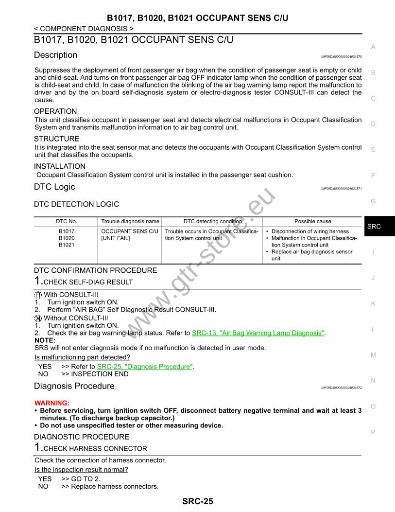
B1017, B1020, B1021 OCCUPANT SENS C/UDescription INFOID:0000000004031570
Suppresses the deployment of front passenger air bag when the condition of passenger seat is empty or childand child-seat. And turns on front passenger air bag OFF indicator lamp when the condition of passenger seatis child-seat and child. In case of malfunction the blinking of the air bag warning lamp report the malfunction todriver and by the on board self-diagnosis system or electro-diagnosis tester CONSULT-III can detect thecause.
OPERATIONThis unit classifies occupant in passenger seat and detects electrical malfunctions in Occupant ClassificationSystem and transmits malfunction information to air bag control unit.
STRUCTUREIt is integrated into the seat sensor mat and detects the occupants with Occupant Classification System controlunit that classifies the occupants.
INSTALLATION Occupant Classification System control unit is installed in the passenger seat cushion.
DTC Logic INFOID:0000000004031571
DTC DETECTION LOGIC
DTC CONFIRMATION PROCEDURE1.CHECK SELF-DIAG RESULT
With CONSULT-III1. Turn ignition switch ON.2. Perform “AIR BAG” Self Diagnostic Result CONSULT-III.
Without CONSULT-III1. Turn ignition switch ON.2. Check the air bag warning lamp status. Refer to SRC-13, "Air Bag Warning Lamp Diagnosis".NOTE:SRS will not enter diagnosis mode if no malfunction is detected in user mode.Is malfunctioning part detected?YES >> Refer to SRC-25, "Diagnosis Procedure".NO >> INSPECTION END
Diagnosis Procedure INFOID:0000000004031572
WARNING:• Before servicing, turn ignition switch OFF, disconnect battery negative terminal and wait at least 3
minutes. (To discharge backup capacitor.)• Do not use unspecified tester or other measuring device.
DIAGNOSTIC PROCEDURE1.CHECK HARNESS CONNECTOR
Check the connection of harness connector.Is the inspection result normal?YES >> GO TO 2.NO >> Replace harness connectors.
DTC No. Trouble diagnosis name DTC detecting condition Possible cause
B1017B1020B1021
OCCUPANT SENS C/U [UNIT FAIL]
Trouble occurs in Occupant Classifica-tion System control unit
• Disconnection of wiring harness• Malfunction in Occupant Classifica-
tion System control unit• Replace air bag diagnosis sensor
unit
www.gtr-
store
.eu
SRC-25
B1017, B1020, B1021 OCCUPANT SENS C/U
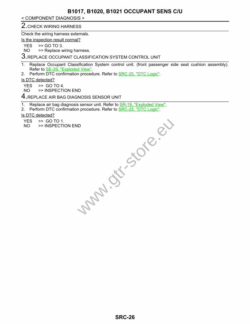
< COMPONENT DIAGNOSIS >2.CHECK WIRING HARNESS
Check the wiring harness externals.Is the inspection result normal?YES >> GO TO 3.NO >> Replace wiring harness.
3.REPLACE OCCUPANT CLASSIFICATION SYSTEM CONTROL UNIT
1. Replace Occupant Classification System control unit. (front passenger side seat cushion assembly).Refer to SE-29, "Exploded View".
2. Perform DTC confirmation procedure. Refer to SRC-25, "DTC Logic".Is DTC detected?YES >> GO TO 4.NO >> INSPECTION END
4.REPLACE AIR BAG DIAGNOSIS SENSOR UNIT
1. Replace air bag diagnosis sensor unit. Refer to SR-19, "Exploded View".2. Perform DTC confirmation procedure. Refer to SRC-25, "DTC Logic".Is DTC detected?YES >> GO TO 1.NO >> INSPECTION END
www.gtr-
store
.eu
SRC-26

B1018 OCCUPANT SENS
C
D
E
F
G
I
J
K
L
M
A
B
RC
N
O
P
< COMPONENT DIAGNOSIS >
S
B1018 OCCUPANT SENSDescription INFOID:0000000004031573
Suppresses the deployment of front passenger air bag when the condition of passenger seat is empty or childand child-seat. And turns on front passenger air bag OFF indicator lamp when the condition of passenger seatis child-seat and child. In case of malfunction the blinking of the air bag warning lamp reports the malfunctionto driver and by the on board self-diagnosis system or electro-diagnosis tester CONSULT-III can detect thecause.
OPERATIONThe unit classifies occupant in passenger seat and transmits it to Occupant Classification System control unit.
STRUCTUREPlural sensors are installed in the sensor mat to prevent incorrect sensing induced by the sitting position.
INSTALLATIONOccupant Classification System sensor is installed in the passenger seat cushion.
DTC Logic INFOID:0000000004031574
DTC DETECTION LOGIC
DTC CONFIRMATION PROCEDURE1.CHECK SELF-DIAG RESULT
With CONSULT-III1. Turn ignition switch ON.2. Perform “AIR BAG” Self Diagnostic Result CONSULT-III.
Without CONSULT-III1. Turn ignition switch ON.2. Check the air bag warning lamp status. Refer to SRC-13, "Air Bag Warning Lamp Diagnosis".NOTE:SRS will not enter diagnosis mode if no malfunction is detected in user mode.Is malfunctioning part detected?YES >> Refer to SRC-27, "Diagnosis Procedure".NO >> INSPECTION END
Diagnosis Procedure INFOID:0000000004031575
WARNING:• Before servicing, turn ignition switch OFF, disconnect battery negative terminal and wait at least 3
minutes. (To discharge backup capacitor.)• Do not use unspecified tester or other measuring device.
DIAGNOSTIC PROCEDURE1.CHECK HARNESS CONNECTOR
Check the connection of harness connector.Is the inspection result normal?YES >> GO TO 2.NO >> Replace harness connectors.
2.CHECK WIRING HARNESS
Check the wiring harness externals.Is the inspection result normal?
DTC No. Trouble diagnosis name DTC detecting condition Possible cause
B1018 OCCUPANT SENS [UNIT FAIL]
Trouble occurs in Occupant Classifica-tion System sensor
• Disconnection of wiring harness• Malfunction in Occupant Classifica-
tion System sensor
www.gtr-
store
.eu
SRC-27

B1018 OCCUPANT SENS
< COMPONENT DIAGNOSIS >YES >> GO TO 3.NO >> Replace wiring harness.3.REPLACE OCCUPANT CLASSIFICATION SYSTEM SENSOR
1. Replace Occupant Classification System sensor. (front passenger side seat cushion frame). Refer to SE-29, "Exploded View".
2. Check “Self diagnostic result” with CONSULT-III.3. Perform DTC confirmation procedure. Refer to SRC-27, "DTC Logic".Is DTC detected?YES >> GO TO 4.NO >> INSPECTION END
4.REPLACE OCCUPANT CLASSIFICATION SYSTEM CONTROL UNIT
1. Replace Occupant Classification System control unit. (front passenger side seat cushion assembly).Refer to SE-29, "Exploded View".
2. Perform DTC confirmation procedure. Refer to SRC-25, "DTC Logic".Is DTC detected?YES >> GO TO 5.NO >> INSPECTION END
5.REPLACE AIR BAG DIAGNOSIS SENSOR UNIT
1. Replace air bag diagnosis sensor unit. Refer to SR-19, "Exploded View".2. Perform DTC confirmation procedure. Refer to SRC-25, "DTC Logic".Is DTC detected?YES >> GO TO 1.NO >> INSPECTION END
www.gtr-
store
.eu
SRC-28

B1022 OCCUPANT SENS C/U
C
D
E
F
G
I
J
K
L
M
A
B
RC
N
O
P
< COMPONENT DIAGNOSIS >
S
B1022 OCCUPANT SENS C/UDescription INFOID:0000000004031576
Suppresses the deployment of front passenger air bag when the condition of passenger seat is empty or childand child-seat. And turns on front passenger air bag OFF indicator lamp when the condition of passenger seatis child-seat and child. In case of malfunction the blinking of the air bag warning lamp reports the malfunctionto driver and by the on board self-diagnosis system or electro-diagnosis tester CONSULT-III can detect thecause.
OPERATIONThis unit classifies occupant in passenger seat and detects electrical malfunction in Occupant ClassificationSystem and transmits malfunction information to air bag control unit.
STRUCTUREIt is integrated into the seat sensor mat and detects the occupants and Occupant Classification System controlunit that classifies the occupants.
INSTALLATION Occupant Classification System control unit is installed in the passenger seat cushion.
DTC Logic INFOID:0000000004031577
DTC DETECTION LOGIC
DTC CONFIRMATION PROCEDURE1.CHECK SELF-DIAG RESULT
With CONSULT-III1. Turn ignition switch ON.2. Perform “AIR BAG” Self Diagnostic Result CONSULT-III.
Without CONSULT-III1. Turn ignition switch ON.2. Check the air bag warning lamp status. Refer to SRC-13, "Air Bag Warning Lamp Diagnosis".NOTE:SRS will not enter diagnosis mode if no malfunction is detected in user mode.Is malfunctioning part detected?YES >> Refer to SRC-29, "Diagnosis Procedure".NO >> INSPECTION END
Diagnosis Procedure INFOID:0000000004031578
WARNING:• Before servicing, turn ignition switch OFF, disconnect battery negative terminal and wait at least 3
minutes. (To discharge backup capacitor.)• Do not use unspecified tester or other measuring device.
DIAGNOSTIC PROCEDURE1.CHECK HARNESS CONNECTOR
Check the connection of harness connector.Is the inspection result normal?YES >> GO TO 2.NO >> Replace harness connectors.
DTC No. Trouble diagnosis name DTC detecting condition Possible cause
B1022 OCCUPANT SENS C/U [COMM FAIL]
Trouble occurs in Occupant Classifica-tion System control unit, circuit of Occu-pant Classification System control unit-Air bag diagnosis sensor unit or Air bag diagnosis sensor unit
• Disconnection of wiring harness• Malfunction in Occupant Classifica-
tion System control unit• Malfunction in air bag diagnosis sen-
sor unit
www.gtr-
store
.eu
SRC-29

B1022 OCCUPANT SENS C/U
< COMPONENT DIAGNOSIS >2.CHECK WIRING HARNESS
Check the wiring harness externals.Is the inspection result normal?YES >> GO TO 3.NO >> Replace wiring harness.
3.CHECK OCCUPANT CLASSIFICATION SYSTEM CONTROL UNIT
1. Replace Occupant Classification System control unit. (front passenger side seat cushion frame). Refer toSE-29, "Exploded View".
2. Perform DTC confirmation procedure. Refer to SRC-29, "DTC Logic".Is DTC detected?YES >> GO TO 4.NO >> INSPECTION END
4.CHECK AIR BAG DIAGNOSIS SENSOR UNIT
1. Replace air bag diagnosis sensor unit. Refer to SE-29, "Exploded View".2. Perform DTC confirmation procedure. Refer to SRC-29, "DTC Logic".Is DTC detected?YES >> GO TO 1.NO >> INSPECTION END
www.gtr-
store
.eu
SRC-30

B1023 PASS A/B INDCTR CKT
C
D
E
F
G
I
J
K
L
M
A
B
RC
N
O
P
< COMPONENT DIAGNOSIS >
S
B1023 PASS A/B INDCTR CKTDescription INFOID:0000000004031579
Suppresses the deployment of front passenger air bag when the condition of passenger seat is empty or occu-pied with a child and child-seat. Also illuminates front passenger air bag OFF indicator lamp when the condi-tion of passenger seat is occupied with a child-seat and child. In case of malfunction the blinking of the air bagwarning lamp reports the malfunction to driver, and by the on board self-diagnosis system or CONSULT-III candetect the cause.
OPERATIONIlluminates front passenger air bag OFF indicator when the passenger seat is empty or occupied by a child ora child-seat.
STRUCTUREFront passenger air bag OFF indicator with LED illumination.
INSTALLATIONFront passenger air bag OFF indicator is installed at the instrument panel center.
DTC Logic INFOID:0000000004031580
DTC DETECTION LOGIC
DTC CONFIRMATION PROCEDURE1.CHECK SELF-DIAG RESULT
With CONSULT-III1. Turn ignition switch ON.2. Perform “AIR BAG” Self Diagnostic Result CONSULT-III.
Without CONSULT-III1. Turn ignition switch ON.2. Check the air bag warning lamp status. Refer to SRC-13, "Air Bag Warning Lamp Diagnosis".NOTE:SRS does not enter diagnosis mode if no malfunction is detected in user mode.Is malfunctioning part detected?YES >> Refer to SRC-31, "Diagnosis Procedure".NO >> INSPECTION END
Diagnosis Procedure INFOID:0000000004031581
WARNING:• Before servicing, turn ignition switch OFF, disconnect battery negative terminal and wait at least 3
minutes. (To discharge backup capacitor.)• Never use unspecified tester or other measuring device.
DIAGNOSTIC PROCEDURE1.CHECK HARNESS CONNECTOR
Check the connection of harness connector.Is the inspection result normal?YES >> GO TO 2.NO >> Replace harness connectors.
DTC No. Trouble diagnosis name DTC detecting condition Possible cause
B1023 PASS A/B INDCTR CKT [UNIT FAIL]
Passenger air bag OFF indicator circuit is open or shorted to ground or the cir-cuits are shorted each other
• Disconnection of wiring harness• Malfunction in front passenger air
bag OFF indicator• Malfunction in air bag diagnosis sen-
sor unit
www.gtr-
store
.eu
SRC-31

B1023 PASS A/B INDCTR CKT
< COMPONENT DIAGNOSIS >2.CHECK WIRING HARNESS
Check the wiring harness externals.Is the inspection result normal?YES >> GO TO 3.NO >> Replace wiring harness.
3.CHECK PASSENGER AIR BAG OFF INDICATOR
1. Replace front passenger air bag OFF indicator. Refer to IP-11, "Exploded View"2. Perform DTC confirmation procedure. Refer to SRC-31, "DTC Logic".Is DTC detected?YES >> GO TO 4.NO >> INSPECTION END
4.REPLACE AIR BAG DIAGNOSIS SENSOR UNIT
1. Replace air bag diagnosis sensor unit. Refer to SR-19, "Exploded View".2. Perform DTC confirmation procedure. Refer to SRC-31, "DTC Logic".Is DTC detected?YES >> GO TO 1.NO >> INSPECTION END
www.gtr-
store
.eu
SRC-32

B1026, B1027, B1028, B1029, B1030, B1031 DIAGNOSIS SENSOR UNIT
C
D
E
F
G
I
J
K
L
M
A
B
RC
N
O
P
< COMPONENT DIAGNOSIS >
S
B1026, B1027, B1028, B1029, B1030, B1031 DIAGNOSIS SENSOR UNITDescription INFOID:0000000004031585
Checks the entire SRS and displays the malfunction either by illuminating or blinking the air bag warning lampon the combination meter. Malfunctioning part can be detected by on board self-diagnosis system and CON-SULT-III.
OPERATIONIt detects a shock that exceeds a specified level and monitors whether the driver and passenger air bags, frontside air bag, side curtain air bag and pre-tensioner seat belts operate normally.
STRUCTUREIt contains the “G” sensors for both frontal and side collisions and spare battery function in case of main bat-tery damage in collision.
INSTALLATIONAir bag diagnosis sensor unit is installed under the center console with fixed bolts.
DTC Logic INFOID:0000000004031586
DTC CONFIRMATION PROCEDURE1.CHECK SELF-DIAG RESULT
With CONSULT-III1. Turn ignition switch ON.2. Perform “AIR BAG” Self Diagnostic Result.
Without CONSULT-III1. Turn ignition switch ON.2. Check the air bag warning lamp status. Refer to SRC-13, "Air Bag Warning Lamp Diagnosis".NOTE:SRS does not enter diagnosis mode if no malfunction is detected in user mode.Is malfunctioning part detected?YES >> Refer to SRC-33, "Diagnosis Procedure".NO >> INSPECTION END
Diagnosis Procedure INFOID:0000000004031587
WARNING:• Before servicing, turn ignition switch OFF, disconnect battery negative terminal and wait at least 3
minutes. (To discharge backup capacitor.)• Never use unspecified tester or other measuring device. 1.CHECK HARNESS CONNECTOR
Check the harness connector.Is the inspection result normal?YES >> GO TO 2.NO >> Replace harness connectors.
2.CHECK WIRING HARNESS
Check the wiring harness externals.Is the inspection result normal?
DTC No. Trouble diagnosis name DTC detecting condition Possible cause
B1026B1027B1028B1029B1030B1031
CONTROL UNIT Air bag diagnosis sensor unit is mal-functioning or out of the specification
• Malfunction in air bag diagnosis sen-sor unit
• Configuration in air bag diagnosis sensor unit does not match the vehi-cles specification
www.gtr-
store
.eu
SRC-33

B1026, B1027, B1028, B1029, B1030, B1031 DIAGNOSIS SENSOR UNIT
< COMPONENT DIAGNOSIS >YES >> GO TO 3.NO >> Replace wiring harness.3.REPLACE AIR BAG DIAGNOSIS SENSOR UNIT
1. Replace air bag diagnosis sensor unit. Refer to SR-19, "Exploded View".2. Perform DTC confirmation procedure. Refer to SRC-33, "DTC Logic".Is DTC detected?YES >> GO TO 1.NO >> INSPECTION END
www.gtr-
store
.eu
SRC-34

B1033, B1034 CRASH ZONE SEN
C
D
E
F
G
I
J
K
L
M
A
B
RC
N
O
P
< COMPONENT DIAGNOSIS >
S
B1033, B1034 CRASH ZONE SENDescription INFOID:0000000004031588
Main “G” sensor generates signal voltage, when it detects deceleration beyond the specified level caused byvehicle frontal collision.
OPERATIONWhen air bag diagnosis sensor unit defines both signal voltage of the “G” sensor and the safing algorithm tobe that of collision which exceeds a specified level, the driving circuit switches on and feeds the electric ignitorof both driver and passenger air bags and pre-tensioner seat belts.
STRUCTUREIntegrated type of the “G” sensor element for frontal collision with output terminals for signal voltage.
INSTALLATIONCrash zone sensor is installed on the radiator core support assembly with fixed nuts.
DTC Logic INFOID:0000000004031589
DTC CONFIRMATION PROCEDURE1.CHECK SELF-DIAG RESULT
With CONSULT-III1. Turn ignition switch ON.2. Perform “AIR BAG” Self Diagnostic Result.
Without CONSULT-III1. Turn ignition switch ON.2. Check the air bag warning lamp status. Refer to SRC-13, "Air Bag Warning Lamp Diagnosis".NOTE:SRS does not enter diagnosis mode if no malfunction is detected in user mode.Is malfunctioning part detected?YES >> Refer to SRC-35, "Diagnosis Procedure".NO >> INSPECTION END
Diagnosis Procedure INFOID:0000000004031590
WARNING:• Before servicing, turn ignition switch OFF, disconnect battery negative terminal and wait at least 3
minutes. (To discharge backup capacitor.)• Never use unspecified tester or other measuring device.1.CHECK HARNESS CONNECTOR
Check the harness connector.Is the inspection result normal?YES >> GO TO 2.NO >> Replace harness connectors.
2.CHECK WIRING HARNESS
Check the wiring harness externals.Is the inspection result normal?YES >> GO TO 3.NO >> Replace wiring harness.
DTC No. Trouble diagnosis name DTC detecting condition Possible cause
B1033B1034
CRASH ZONE SEN-SOR [UNIT FAIL]
Crash zone sensor is malfunctioning • Disconnection of wiring harness• Malfunction in crash zone sensor• Malfunction in air bag diagnosis sen-
sor unit
www.gtr-
store
.eu
SRC-35
B1033, B1034 CRASH ZONE SEN
< COMPONENT DIAGNOSIS >3.REPLACE CRASH ZONE SENSOR
1. Replace crash zone sensor. Refer to SR-15, "Exploded View".2. Perform DTC confirmation procedure. Refer to SRC-35, "DTC Logic".Is DTC detected?YES >> GO TO 4.NO >> INSPECTION END
4.REPLACE AIR BAG DIAGNOSIS SENSOR UNIT
1. Replace air bag diagnosis sensor unit. Refer to SR-19, "Exploded View".2. Perform DTC confirmation procedure. Refer to SRC-35, "DTC Logic".Is DTC detected?YES >> GO TO 1.NO >> INSPECTION END
www.gtr-
store
.eu
SRC-36

B1035, B1036 CRASH ZONE SEN
C
D
E
F
G
I
J
K
L
M
A
B
RC
N
O
P
< COMPONENT DIAGNOSIS >
S
B1035, B1036 CRASH ZONE SENDescription INFOID:0000000004031591
Main “G” sensor generates signal voltage, when it detects deceleration beyond the specified level caused byvehicle frontal collision.
OPERATIONWhen air bag diagnosis sensor unit defines both signal voltage of the “G” sensor and the safing algorithm tobe that of collision which exceeds a specified level, the driving circuit switches on and feeds the electric ignitorof both driver and passenger air bags and pre-tensioner seat belts.
STRUCTUREIntegrated type of the “G” sensor element for frontal collision with output terminals for signal voltage.
INSTALLATIONCrash zone sensor is installed on the radiator core support assembly with fixed nuts.
DTC Logic INFOID:0000000004031592
DTC CONFIRMATION PROCEDURE1.CHECK SELF-DIAG RESULT
With CONSULT-III1. Turn ignition switch ON.2. Perform “AIR BAG” Self Diagnostic Result.
Without CONSULT-III1. Turn ignition switch ON.2. Check the air bag warning lamp status. Refer to SRC-13, "Air Bag Warning Lamp Diagnosis".NOTE:SRS does not enter diagnosis mode if no malfunction is detected in user mode.Is malfunctioning part detected?YES >> Refer to SRC-37, "Diagnosis Procedure".NO >> INSPECTION END
Diagnosis Procedure INFOID:0000000004031593
WARNING:• Before servicing, turn ignition switch OFF, disconnect battery negative terminal and wait at least 3
minutes. (To discharge backup capacitor.)• Never use unspecified tester or other measuring device. 1.CHECK HARNESS CONNECTOR
Check the harness connector.Is the inspection result normal?YES >> GO TO 2.NO >> Replace harness connectors.
2.CHECK WIRING HARNESS
Check the wiring harness externals.Is the inspection result normal?YES >> GO TO 3.NO >> Replace wiring harness.
DTC No. Trouble diagnosis name DTC detecting condition Possible cause
B1035B1036
CRASH ZONE SEN-SOR [COMM FAIL][UNMATCH]
Crash zone sensor is malfunctioning or out of the specified specification
• Disconnection of wiring harness• Malfunction in crash zone sensor• Malfunction in air bag diagnosis sen-
sor unit
www.gtr-
store
.eu
SRC-37

B1035, B1036 CRASH ZONE SEN
< COMPONENT DIAGNOSIS >3.REPLACE CRASH ZONE SENSOR
1. Replace crash zone sensor. Refer to SR-15, "Exploded View".2. Perform DTC confirmation procedure. Refer to SRC-37, "DTC Logic".Is DTC detected?YES >> GO TO 4.NO >> INSPECTION END
4.REPLACE AIR BAG DIAGNOSIS SENSOR UNIT
1. Replace air bag diagnosis sensor unit. Refer to SR-19, "Exploded View".2. Perform DTC confirmation procedure. Refer to SRC-37, "DTC Logic".Is DTC detected?YES >> GO TO 1.NO >> INSPECTION END
www.gtr-
store
.eu
SRC-38

B1042, B1043, B1044, B1045, B1046, B1047 DIAGNOSIS SENSOR UNIT
C
D
E
F
G
I
J
K
L
M
A
B
RC
N
O
P
< COMPONENT DIAGNOSIS >
S
B1042, B1043, B1044, B1045, B1046, B1047 DIAGNOSIS SENSOR UNITDescription INFOID:0000000004031597
Checks the entire SRS and displays the malfunction either by illuminating or blinking the air bag warning lampon the combination meter. Malfunctioning part can be detected by on board self-diagnosis system and CON-SULT-III.
OPERATIONIt detects a shock that exceeds a specified level and monitors whether the driver and passenger air bags, frontside air bag, side curtain air bag and pre-tensioner seat belts operate normally.
STRUCTUREIt contains the “G” sensors for both frontal and side collisions and spare battery function in case of main bat-tery damage in collision.
INSTALLATIONAir bag diagnosis sensor unit is installed under the center console with fixed bolts.
DTC Logic INFOID:0000000004031598
DTC CONFIRMATION PROCEDURE1.CHECK SELF-DIAG RESULT
With CONSULT-III1. Turn ignition switch ON.2. Perform “AIR BAG” Self Diagnostic Result.
Without CONSULT-III1. Turn ignition switch ON.2. Check the air bag warning lamp status. Refer to SRC-13, "Air Bag Warning Lamp Diagnosis".NOTE:SRS does not enter diagnosis mode if no malfunction is detected in user mode.Is malfunctioning part detected?YES >> Refer to SRC-39, "Diagnosis Procedure".NO >> INSPECTION END
Diagnosis Procedure INFOID:0000000004031599
WARNING:• Before servicing, turn ignition switch OFF, disconnect battery negative terminal and wait at least 3
minutes. (To discharge backup capacitor.)• Never use unspecified tester or other measuring device. 1.CHECK HARNESS CONNECTOR
Check the harness connector.Is the inspection result normal?YES >> GO TO 2.NO >> Replace harness connectors.
2.CHECK WIRING HARNESS
Check the wiring harness externals.Is the inspection result normal?
DTC No. Trouble diagnosis name DTC detecting condition Possible cause
B1042B1043B1044B1045B1046B1047
CONTROL UNIT Air bag diagnosis sensor unit is mal-functioning or out of the specification
• Malfunction in air bag diagnosis sen-sor unit
• Configuration in air bag diagnosis sensor unit does not match the vehi-cles specification
www.gtr-
store
.eu
SRC-39

B1042, B1043, B1044, B1045, B1046, B1047 DIAGNOSIS SENSOR UNIT
< COMPONENT DIAGNOSIS >YES >> GO TO 3.NO >> Replace wiring harness.3.REPLACE AIR BAG DIAGNOSIS SENSOR UNIT
1. Replace air bag diagnosis sensor unit. Refer to SR-19, "Exploded View".2. Perform DTC confirmation procedure. Refer to SRC-39, "DTC Logic".Is DTC detected?YES >> GO TO 1.NO >> INSPECTION END
www.gtr-
store
.eu
SRC-40
B1049, B1054 DRIVER AIRBAG MODULE
C
D
E
F
G
I
J
K
L
M
A
B
RC
N
O
P
< COMPONENT DIAGNOSIS >
S
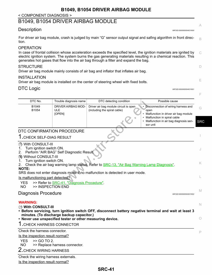
B1049, B1054 DRIVER AIRBAG MODULEDescription INFOID:0000000004031600
For driver air bag module, crash is judged by main “G” sensor output signal and safing algorithm in front direc-tion.
OPERATIONIn case of frontal collision whose acceleration exceeds the specified level, the ignition materials are ignited byelectric ignition system. The system burns the gas generating materials resulting in a chemical reaction. Thisgenerates hot gases that flow into the air bag through a filter and expand the bag.
STRUCTUREDriver air bag module mainly consists of air bag and inflator that inflates air bag.
INSTALLATIONDriver air bag module is installed on the center of steering wheel with fixed bolts.
DTC Logic INFOID:0000000004031601
DTC CONFIRMATION PROCEDURE1.CHECK SELF-DIAG RESULT
With CONSULT-III1. Turn ignition switch ON.2. Perform “AIR BAG” Self Diagnostic Result.
Without CONSULT-III1. Turn ignition switch ON.2. Check the air bag warning lamp status. Refer to SRC-13, "Air Bag Warning Lamp Diagnosis".NOTE:SRS does not enter diagnosis mode if no malfunction is detected in user mode.Is malfunctioning part detected?YES >> Refer to SRC-41, "Diagnosis Procedure".NO >> INSPECTION END
Diagnosis Procedure INFOID:0000000004031602
WARNING: With CONSULT-III
• Before servicing, turn ignition switch OFF, disconnect battery negative terminal and wait at least 3minutes. (To discharge backup capacitor.)
• Never use unspecified tester or other measuring device. 1.CHECK HARNESS CONNECTOR
Check the harness connector.Is the inspection result normal?YES >> GO TO 2.NO >> Replace harness connector.
2.CHECK WIRING HARNESS
Check the wiring harness externals.Is the inspection result normal?
DTC No. Trouble diagnosis name DTC detecting condition Possible cause
B1049B1054
DRIVER AIRBAG MOD-ULE[OPEN]
Driver air bag module circuit is open(including the spiral cable)
• Disconnection of wiring harness and open
• Malfunction in driver air bag module• Malfunction in spiral cable• Malfunction in air bag diagnosis sen-
sor unit
www.gtr-
store
.eu
SRC-41

B1049, B1054 DRIVER AIRBAG MODULE
< COMPONENT DIAGNOSIS >YES >> GO TO 3.NO >> Replace wiring harness.3.CHECK SPIRAL CABLE CIRCUIT
1. Turn ignition switch OFF.2. Disconnect driver air bag module harness connector and combination switch (spiral cable) harness con-
nector.3. Check continuity between driver air bag module harness connector and combination switch (spiral cable)
harness connector.
4. Check continuity between driver air bag module harness connector and ground.
Is the inspection result normal?YES >> GO TO 4.NO >> Replace combination switch (spiral cable). Refer to SR-8, "Exploded View".
4.REPLACE DRIVER AIR BAG MODULE
1. Replace driver air bag module. Refer to SR-5, "Exploded View"2. Perform DTC confirmation procedure. Refer to SRC-41, "DTC Logic".Is DTC detected?YES >> GO TO 5.NO >> INSPECTION END
5.REPLACE AIR BAG DIAGNOSIS SENSOR UNIT
1. Replace air bag diagnosis sensor unit. Refer to SR-19, "Exploded View"2. Perform DTC confirmation procedure. Refer to SRC-41, "DTC Logic".Is DTC detected?YES >> GO TO 1.NO >> INSPECTION END
Driver air bag module har-ness connector Terminal
combination switch (spiral ca-ble) harness connector
Terminal Continuity
M30210
M35
28
Existed11 30
M30112 29
9 30
Driver side air bag module harness con-nector Terminal
Ground
Continuity
M30210
Not existed11
M30112
9
www.gtr-
store
.eu
SRC-42

B1050, B1055 DRIVER AIRBAG MODULE
C
D
E
F
G
I
J
K
L
M
A
B
RC
N
O
P
< COMPONENT DIAGNOSIS >
S
B1050, B1055 DRIVER AIRBAG MODULEDescription INFOID:0000000004031603
For driver air bag module, crash is judged by main “G” sensor output signal and safing algorithm in front direc-tion.
OPERATIONIn case of frontal collision whose acceleration exceeds the specified level, the ignition materials are ignited byelectric ignition system. The system burns the gas generating materials resulting in a chemical reaction. Thisgenerates hot gases that flow into the air bag through a filter and expand the bag.
STRUCTUREDriver air bag module mainly consists of air bag and inflator that inflates air bag.
INSTALLATIONDriver air bag module is installed on the center of steering wheel with fixed bolts.
DTC Logic INFOID:0000000004031604
DTC CONFIRMATION PROCEDURE1.CHECK SELF-DIAG RESULT
With CONSULT-III1. Turn ignition switch ON.2. Perform “AIR BAG” Self Diagnostic Result.
Without CONSULT-III1. Turn ignition switch ON.2. Check the air bag warning lamp status. Refer to SRC-13, "Air Bag Warning Lamp Diagnosis".NOTE:SRS does not enter diagnosis mode if no malfunction is detected in user mode.Is malfunctioning part detected?YES >> Refer to SRC-43, "Diagnosis Procedure".NO >> INSPECTION END
Diagnosis Procedure INFOID:0000000004031605
WARNING:• Before servicing, turn ignition switch OFF, disconnect battery negative terminal and wait at least 3
minutes. (To discharge backup capacitor.)• Never use unspecified tester or other measuring device. 1.CHECK HARNESS CONNECTOR
Check the harness connector.Is the inspection result normal?YES >> GO TO 2.NO >> Replace harness connector.
2.CHECK WIRING HARNESS
Check the wiring harness externals.Is the inspection result normal?YES >> GO TO 3.
DTC No. Trouble diagnosis name DTC detecting condition Possible cause
B1050B1055
DRIVER AIRBAG MOD-ULE [VB-SHORT]
Driver air bag module circuit is shorted to some power supply circuit(including the spiral cable)
• Disconnection of wiring harness and short
• Malfunction in driver air bag module• Malfunction in spiral cable• Malfunction in air bag diagnosis sen-
sor unit
www.gtr-
store
.eu
SRC-43

B1050, B1055 DRIVER AIRBAG MODULE
< COMPONENT DIAGNOSIS >NO >> Replace wiring harness.3.CHECK SPIRAL CABLE CIRCUIT
1. Turn ignition switch OFF.2. Disconnect driver air bag module harness connector and combination switch (spiral cable) harness con-
nector.3. Check continuity between driver air bag module harness connector and combination switch (spiral cable)
harness connector.
4. Check continuity between driver air bag module harness connector and ground.
Is the inspection result normal?YES >> GO TO 4.NO >> Replace combination switch (spiral cable). Refer to SR-8, "Exploded View".
4.REPLACE DRIVER AIR BAG MODULE
1. Replace driver air bag module. Refer to SR-5, "Exploded View"2. Perform DTC confirmation procedure. Refer to SRC-41, "DTC Logic".Is DTC detected?YES >> GO TO 5.NO >> INSPECTION END
5.REPLACE AIR BAG DIAGNOSIS SENSOR UNIT
1. Replace air bag diagnosis sensor unit. Refer to SR-19, "Exploded View".2. Perform DTC confirmation procedure. Refer to SRC-43, "DTC Logic".Is DTC detected?YES >> GO TO 1.NO >> INSPECTION END
Driver air bag module har-ness connector Terminal
combination switch (spiral ca-ble) harness connector
Terminal Continuity
M30210
M35
28
Existed11 30
M30112 29
9 30
Driver side air bag module harness con-nector Terminal
Ground
Continuity
M30210
Not existed11
M30112
9
www.gtr-
store
.eu
SRC-44
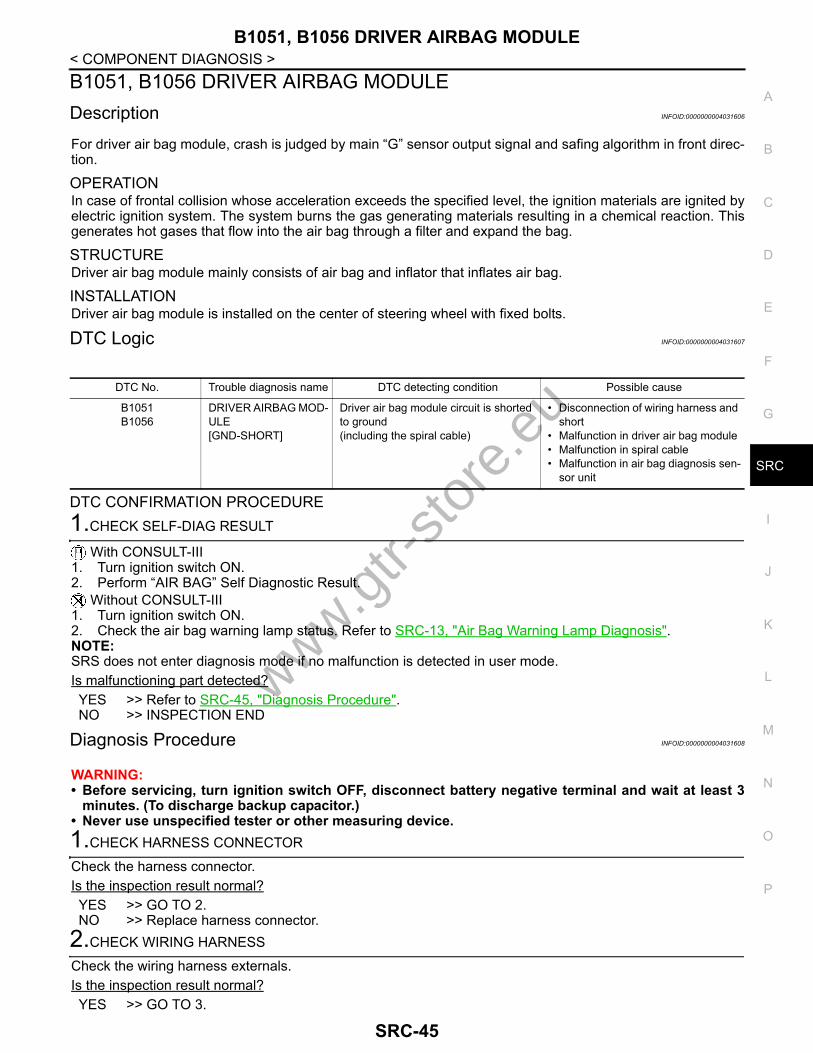
B1051, B1056 DRIVER AIRBAG MODULE
C
D
E
F
G
I
J
K
L
M
A
B
RC
N
O
P
< COMPONENT DIAGNOSIS >
S
B1051, B1056 DRIVER AIRBAG MODULEDescription INFOID:0000000004031606
For driver air bag module, crash is judged by main “G” sensor output signal and safing algorithm in front direc-tion.
OPERATIONIn case of frontal collision whose acceleration exceeds the specified level, the ignition materials are ignited byelectric ignition system. The system burns the gas generating materials resulting in a chemical reaction. Thisgenerates hot gases that flow into the air bag through a filter and expand the bag.
STRUCTUREDriver air bag module mainly consists of air bag and inflator that inflates air bag.
INSTALLATIONDriver air bag module is installed on the center of steering wheel with fixed bolts.
DTC Logic INFOID:0000000004031607
DTC CONFIRMATION PROCEDURE1.CHECK SELF-DIAG RESULT
With CONSULT-III1. Turn ignition switch ON.2. Perform “AIR BAG” Self Diagnostic Result.
Without CONSULT-III1. Turn ignition switch ON.2. Check the air bag warning lamp status. Refer to SRC-13, "Air Bag Warning Lamp Diagnosis".NOTE:SRS does not enter diagnosis mode if no malfunction is detected in user mode.Is malfunctioning part detected?YES >> Refer to SRC-45, "Diagnosis Procedure".NO >> INSPECTION END
Diagnosis Procedure INFOID:0000000004031608
WARNING:• Before servicing, turn ignition switch OFF, disconnect battery negative terminal and wait at least 3
minutes. (To discharge backup capacitor.)• Never use unspecified tester or other measuring device. 1.CHECK HARNESS CONNECTOR
Check the harness connector.Is the inspection result normal?YES >> GO TO 2.NO >> Replace harness connector.
2.CHECK WIRING HARNESS
Check the wiring harness externals.Is the inspection result normal?YES >> GO TO 3.
DTC No. Trouble diagnosis name DTC detecting condition Possible cause
B1051B1056
DRIVER AIRBAG MOD-ULE [GND-SHORT]
Driver air bag module circuit is shorted to ground(including the spiral cable)
• Disconnection of wiring harness and short
• Malfunction in driver air bag module• Malfunction in spiral cable• Malfunction in air bag diagnosis sen-
sor unit
www.gtr-
store
.eu
SRC-45
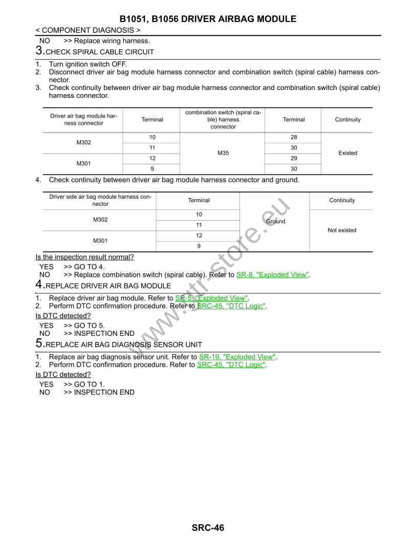
B1051, B1056 DRIVER AIRBAG MODULE
< COMPONENT DIAGNOSIS >NO >> Replace wiring harness.3.CHECK SPIRAL CABLE CIRCUIT
1. Turn ignition switch OFF.2. Disconnect driver air bag module harness connector and combination switch (spiral cable) harness con-
nector.3. Check continuity between driver air bag module harness connector and combination switch (spiral cable)
harness connector.
4. Check continuity between driver air bag module harness connector and ground.
Is the inspection result normal?YES >> GO TO 4.NO >> Replace combination switch (spiral cable). Refer to SR-8, "Exploded View".
4.REPLACE DRIVER AIR BAG MODULE
1. Replace driver air bag module. Refer to SR-5, "Exploded View".2. Perform DTC confirmation procedure. Refer to SRC-45, "DTC Logic".Is DTC detected?YES >> GO TO 5.NO >> INSPECTION END
5.REPLACE AIR BAG DIAGNOSIS SENSOR UNIT
1. Replace air bag diagnosis sensor unit. Refer to SR-19, "Exploded View".2. Perform DTC confirmation procedure. Refer to SRC-45, "DTC Logic".Is DTC detected?YES >> GO TO 1.NO >> INSPECTION END
Driver air bag module har-ness connector Terminal
combination switch (spiral ca-ble) harness connector
Terminal Continuity
M30210
M35
28
Existed11 30
M30112 29
9 30
Driver side air bag module harness con-nector Terminal
Ground
Continuity
M30210
Not existed11
M30112
9
www.gtr-
store
.eu
SRC-46

B1052, B1057 DRIVER AIRBAG MODULE
C
D
E
F
G
I
J
K
L
M
A
B
RC
N
O
P
< COMPONENT DIAGNOSIS >
S
B1052, B1057 DRIVER AIRBAG MODULEDescription INFOID:0000000004031609
For driver air bag module, crash is judged by main “G” sensor output signal and safing algorithm in front direc-tion.
OPERATIONIn case of frontal collision whose acceleration exceeds the specified level, the ignition materials are ignited byelectric ignition system. The system burns the gas generating materials resulting in a chemical reaction. Thisgenerates hot gases that flow into the air bag through a filter and expand the bag.
STRUCTUREDriver air bag module mainly consists of air bag and inflator that inflates air bag.
INSTALLATIONDriver air bag module is installed on the center of steering wheel with fixed bolts.
DTC Logic INFOID:0000000004031610
DTC CONFIRMATION PROCEDURE1.CHECK SELF-DIAG RESULT
With CONSULT-III1. Turn ignition switch ON.2. Perform “AIR BAG” Self Diagnostic Result.
Without CONSULT-III1. Turn ignition switch ON.2. Check the air bag warning lamp status. Refer to SRC-13, "Air Bag Warning Lamp Diagnosis".NOTE:SRS does not enter diagnosis mode if no malfunction is detected in user mode.Is malfunctioning part detected?YES >> Refer to SRC-47, "Diagnosis Procedure".NO >> INSPECTION END
Diagnosis Procedure INFOID:0000000004031611
WARNING:• Before servicing, turn ignition switch OFF, disconnect battery negative terminal and wait at least 3
minutes. (To discharge backup capacitor.)• Never use unspecified tester or other measuring device. 1.CHECK HARNESS CONNECTOR
Check the harness connector.Is the inspection result normal?YES >> GO TO 2.NO >> Replace harness connector.
2.CHECK WIRING HARNESS
Check the wiring harness externals.Is the inspection result normal?YES >> GO TO 3.
DTC No. Trouble diagnosis name DTC detecting condition Possible cause
B1052B1057
DRIVER AIRBAG MOD-ULE [SHORT]
Driver air bag module circuit are shorted to each other(including the spiral cable)
• Disconnection of wiring harnessand short
• Malfunction in driver air bag module• Malfunction in spiral cable• Malfunction in air bag diagnosis sen-
sor unit
www.gtr-
store
.eu
SRC-47

B1052, B1057 DRIVER AIRBAG MODULE
< COMPONENT DIAGNOSIS >NO >> Replace wiring harness.3.CHECK SPIRAL CABLE CIRCUIT
1. Turn ignition switch OFF.2. Disconnect driver air bag module harness connector and combination switch (spiral cable) harness con-
nector.3. Check continuity between driver air bag module harness connector and combination switch (spiral cable)
harness connector.
4. Check continuity between driver air bag module harness connector and ground.
Is the inspection result normal?YES >> GO TO 4.NO >> Replace combination switch (spiral cable). Refer to SR-8, "Exploded View".
4.REPLACE DRIVER AIR BAG MODULE
1. Replace driver air bag module. Refer to SR-5, "Exploded View".2. Perform DTC confirmation procedure. Refer to SRC-47, "DTC Logic".Is DTC detected?YES >> GO TO 5.NO >> INSPECTION END
5.REPLACE AIR BAG DIAGNOSIS SENSOR UNIT
1. Replace air bag diagnosis sensor unit. Refer to SR-19, "Exploded View".2. Perform DTC confirmation procedure. Refer to SRC-47, "DTC Logic".Is DTC detected?YES >> GO TO 1.NO >> INSPECTION END
Driver air bag module har-ness connector Terminal
combination switch (spiral ca-ble) harness connector
Terminal Continuity
M30210
M35
28
Existed11 30
M30112 29
9 30
Driver side air bag module harness con-nector Terminal
Ground
Continuity
M30210
Not existed11
M30112
9
www.gtr-
store
.eu
SRC-48

B1058, B1059, B1060, B1061, B1062, B1063 DIAGNOSIS SENSOR UNIT
C
D
E
F
G
I
J
K
L
M
A
B
RC
N
O
P
< COMPONENT DIAGNOSIS >
S
B1058, B1059, B1060, B1061, B1062, B1063 DIAGNOSIS SENSOR UNITDescription INFOID:0000000004031612
Checks the entire SRS and displays the malfunction either by illuminating or blinking the air bag warning lampon the combination meter. Malfunctioning part can be detected by on board self-diagnosis system and CON-SULT-III.
OPERATIONIt detects a shock that exceeds a specified level and monitors whether the driver and passenger air bags, frontside air bag, side curtain air bag and pre-tensioner seat belts operate normally.
STRUCTUREIt contains the “G” sensors for both frontal and side collisions and spare battery function in case of main bat-tery damage in collision.
INSTALLATIONAir bag diagnosis sensor unit is installed under the center console with fixed bolts.
DTC Logic INFOID:0000000004031613
DTC CONFIRMATION PROCEDURE1.CHECK SELF-DIAG RESULT
With CONSULT-III1. Turn ignition switch ON.2. Perform “AIR BAG” Self Diagnostic Result.
Without CONSULT-III1. Turn ignition switch ON.2. Check the air bag warning lamp status. Refer to SRC-13, "Air Bag Warning Lamp Diagnosis".NOTE:SRS does not enter diagnosis mode if no malfunction is detected in user mode.Is malfunctioning part detected?YES >> Refer to SRC-49, "Diagnosis Procedure".NO >> INSPECTION END
Diagnosis Procedure INFOID:0000000004031614
WARNING:• Before servicing, turn ignition switch OFF, disconnect battery negative terminal and wait at least 3
minutes. (To discharge backup capacitor.)• Never use unspecified tester or other measuring device. 1.CHECK HARNESS CONNECTOR
Check the harness connector.Is the inspection result normal?YES >> GO TO 2.NO >> Replace harness connectors.
2.CHECK WIRING HARNESS
Check the wiring harness externals.Is the inspection result normal?
DTC No. Trouble diagnosis name DTC detecting condition Possible cause
B1058B1059B1060B1061B1062B1063
CONTROL UNIT Air bag diagnosis sensor unit is mal-functioning or out of the specification
• Malfunction in air bag diagnosis sen-sor unit
• Configuration in air bag diagnosis sensor unit does not match the vehi-cles specification
www.gtr-
store
.eu
SRC-49

B1058, B1059, B1060, B1061, B1062, B1063 DIAGNOSIS SENSOR UNIT
< COMPONENT DIAGNOSIS >YES >> GO TO 3.NO >> Replace wiring harness.3.REPLACE AIR BAG DIAGNOSIS SENSOR UNIT
1. Replace air bag diagnosis sensor unit. Refer to SR-19, "Exploded View".2. Perform DTC confirmation procedure. Refer to SRC-49, "DTC Logic".Is DTC detected?YES >> GO TO 1.NO >> INSPECTION END
www.gtr-
store
.eu
SRC-50

B1065, B1070 ASSIST A/B MODULE
C
D
E
F
G
I
J
K
L
M
A
B
RC
N
O
P
< COMPONENT DIAGNOSIS >
S
B1065, B1070 ASSIST A/B MODULEDescription INFOID:0000000004031615
For front passenger air bag module, crash is judged by main “G” sensor output signal and safing algorithm infront direction.
OPERATIONIn case of frontal collision whose acceleration exceeds the specified level, the ignition materials are ignited byelectric ignition system. The system burns the gas generating materials resulting in a chemical reaction. Thisgenerates hot gases that flow into the air bag through a filter and expand the bag.
STRUCTUREFront passenger air bag module mainly consists of air bag and inflator that inflates air bag.
INSTALLATIONFront passenger air bag module is installed on the instrument panel with fixed bolts.
DTC Logic INFOID:0000000004031616
DTC CONFIRMATION PROCEDURE1.CHECK SELF-DIAG RESULT
With CONSULT-III1. Turn ignition switch ON.2. Perform “AIR BAG” Self Diagnostic Result.
Without CONSULT-III1. Turn ignition switch ON.2. Check the air bag warning lamp status. Refer to SRC-13, "Air Bag Warning Lamp Diagnosis".NOTE:SRS does not enter diagnosis mode if no malfunction is detected in user mode.Is malfunctioning part detected?YES >> Refer to SRC-51, "Diagnosis Procedure".NO >> INSPECTION END
Diagnosis Procedure INFOID:0000000004031617
WARNING:• Before servicing, turn ignition switch OFF, disconnect battery negative terminal and wait at least 3
minutes. (To discharge backup capacitor.)• Never use unspecified tester or other measuring device.1.CHECK HARNESS CONNECTOR
Check the harness connector.Is the inspection result normal?YES >> GO TO 2.NO >> Replace harness connector.
2.CHECK WIRING HARNESS
Check the wiring harness externals.Is the inspection result normal?YES >> GO TO 3.
DTC No. Trouble diagnosis name DTC detecting condition Possible cause
B1065B1070
ASSIST A/B MODULE [OPEN]
Front passenger air bag module circuit is open
• Disconnection of wiring harness and open
• Malfunction in front passenger air bag module
• Malfunction in air bag diagnosis sen-sor unit
www.gtr-
store
.eu
SRC-51
B1065, B1070 ASSIST A/B MODULE
< COMPONENT DIAGNOSIS >NO >> Replace wiring harness.3.REPLACE FRONT PASSENGER AIR BAG MODULE
1. Replace front passenger air bag module. Refer to SR-11, "Exploded View"2. Perform DTC confirmation procedure. Refer to SRC-51, "DTC Logic".Is DTC detected?YES >> GO TO 4.NO >> INSPECTION END
4.REPLACE AIR BAG DIAGNOSIS SENSOR UNIT
1. Replace air bag diagnosis sensor unit. Refer to SR-19, "Exploded View".2. Perform DTC confirmation procedure. Refer to SRC-51, "DTC Logic".Is DTC detected?YES >> GO TO 1.NO >> INSPECTION END
www.gtr-
store
.eu
SRC-52

B1066, B1071 ASSIST A/B MODULE
C
D
E
F
G
I
J
K
L
M
A
B
RC
N
O
P
< COMPONENT DIAGNOSIS >
S
B1066, B1071 ASSIST A/B MODULEDescription INFOID:0000000004031618
For front passenger air bag module, crash is judged by main “G” sensor output signal and safing algorithm infront direction.
OPERATIONIn case of frontal collision whose acceleration exceeds the specified level, the ignition materials are ignited byelectric ignition system. The system burns the gas generating materials resulting in a chemical reaction. Thisgenerates hot gases that flow into the air bag through a filter and expand the bag.
STRUCTUREFront passenger air bag module mainly consists of air bag and inflator that inflates air bag.
INSTALLATIONFront passenger air bag module is installed on the instrument panel with fixed bolts.
DTC Logic INFOID:0000000004031619
DTC CONFIRMATION PROCEDURE1.CHECK SELF-DIAG RESULT
With CONSULT-III1. Turn ignition switch ON.2. Perform “AIR BAG” Self Diagnostic Result.
Without CONSULT-III1. Turn ignition switch ON.2. Check the air bag warning lamp status. Refer to SRC-13, "Air Bag Warning Lamp Diagnosis".NOTE:SRS does not enter diagnosis mode if no malfunction is detected in user mode.Is malfunctioning part detected?YES >> Refer to SRC-53, "Diagnosis Procedure".NO >> INSPECTION END
Diagnosis Procedure INFOID:0000000004031620
WARNING:• Before servicing, turn ignition switch OFF, disconnect battery negative terminal and wait at least 3
minutes. (To discharge backup capacitor.)• Never use unspecified tester or other measuring device.1.CHECK HARNESS CONNECTOR
Check the harness connector.Is the inspection result normal?YES >> GO TO 2.NO >> Replace harness connector.
2.CHECK WIRING HARNESS
Check the wiring harness externals.Is the inspection result normal?YES >> GO TO 3.
DTC No. Trouble diagnosis name DTC detecting condition Possible cause
B1066B1071
ASSIST A/B MODULE [VB-SHORT]
Front passenger air bag module circuit is shorted to some power supply circuit
• Disconnection of wiring harness and short
• Malfunction in front passenger air bag module
• Malfunction in air bag diagnosis sen-sor unit
www.gtr-
store
.eu
SRC-53

B1066, B1071 ASSIST A/B MODULE
< COMPONENT DIAGNOSIS >NO >> Replace wiring harness.3.REPLACE FRONT PASSENGER AIR BAG MODULE
1. Replace front passenger air bag module. Refer to SR-11, "Exploded View".2. Perform DTC confirmation procedure. Refer to SRC-53, "DTC Logic".Is DTC detected?YES >> GO TO 4.NO >> INSPECTION END
4.REPLACE AIR BAG DIAGNOSIS SENSOR UNIT
1. Replace air bag diagnosis sensor unit. Refer to SR-19, "Exploded View".2. Perform DTC confirmation procedure. Refer to SRC-53, "DTC Logic".Is DTC detected?YES >> GO TO 1.NO >> INSPECTION END
www.gtr-
store
.eu
SRC-54

B1067, B1072 ASSIST A/B MODULE
C
D
E
F
G
I
J
K
L
M
A
B
RC
N
O
P
< COMPONENT DIAGNOSIS >
S
B1067, B1072 ASSIST A/B MODULEDescription INFOID:0000000004031621
For front passenger air bag module, crash is judged by main “G” sensor output signal and safing algorithm infront direction.
OPERATIONIn case of frontal collision whose acceleration exceeds the specified level, the ignition materials are ignited byelectric ignition system. The system burns the gas generating materials resulting in a chemical reaction. Thisgenerates hot gases that flow into the air bag through a filter and expand the bag.
STRUCTUREFront passenger air bag module mainly consists of air bag and inflator that inflates air bag.
INSTALLATIONFront passenger air bag module is installed on the instrument panel with fixed bolts.
DTC Logic INFOID:0000000004031622
DTC CONFIRMATION PROCEDURE1.CHECK SELF-DIAG RESULT
With CONSULT-III1. Turn ignition switch ON.2. Perform “AIR BAG” Self Diagnostic Result.
Without CONSULT-III1. Turn ignition switch ON.2. Check the air bag warning lamp status. Refer to SRC-13, "Air Bag Warning Lamp Diagnosis".NOTE:SRS does not enter diagnosis mode if no malfunction is detected in user mode.Is malfunctioning part detected?YES >> Refer to SRC-55, "Diagnosis Procedure".NO >> INSPECTION END
Diagnosis Procedure INFOID:0000000004031623
WARNING:• Before servicing, turn ignition switch OFF, disconnect battery negative terminal and wait at least 3
minutes. (To discharge backup capacitor.)• Never use unspecified tester or other measuring device.1.CHECK HARNESS CONNECTOR
Check the harness connector.Is the inspection result normal?YES >> GO TO 2.NO >> Replace harness connector.
2.CHECK WIRING HARNESS
Check the wiring harness externals.Is the inspection result normal?YES >> GO TO 3.
DTC No. Trouble diagnosis name DTC detecting condition Possible cause
B1067B1072
ASSIST A/B MODULE [GND-SHORT]
Front passenger air bag module circuit is shorted to ground
• Disconnection of wiring harness and short
• Malfunction in front passenger air bag module
• Malfunction in air bag diagnosis sen-sor unit
www.gtr-
store
.eu
SRC-55

B1067, B1072 ASSIST A/B MODULE
< COMPONENT DIAGNOSIS >NO >> Replace wiring harness.3.REPLACE FRONT PASSENGER AIR BAG MODULE
1. Replace front passenger air bag module. Refer to SR-11, "Exploded View"2. Perform DTC confirmation procedure. Refer to SRC-55, "DTC Logic".Is DTC detected?YES >> GO TO 4.NO >> INSPECTION END
4.REPLACE AIR BAG DIAGNOSIS SENSOR UNIT
1. Replace air bag diagnosis sensor unit. Refer to SR-19, "Exploded View".2. Perform DTC confirmation procedure. Refer to SRC-55, "DTC Logic".Is DTC detected?YES >> GO TO 1.NO >> INSPECTION END
www.gtr-
store
.eu
SRC-56

B1068, B1073 ASSIST A/B MODULE
C
D
E
F
G
I
J
K
L
M
A
B
RC
N
O
P
< COMPONENT DIAGNOSIS >
S
B1068, B1073 ASSIST A/B MODULEDescription INFOID:0000000004031624
For front passenger air bag module, crash is judged by main “G” sensor output signal and safing algorithm infront direction.
OPERATIONIn case of frontal collision whose acceleration exceeds the specified level, the ignition materials are ignited byelectric ignition system. The system burns the gas generating materials resulting in a chemical reaction. Thisgenerates hot gases that flow into the air bag through a filter and expand the bag.
STRUCTUREFront passenger air bag module mainly consists of air bag and inflator that inflates air bag.
INSTALLATIONFront passenger air bag module is installed on the instrument panel with fixed bolts.
DTC Logic INFOID:0000000004031625
DTC CONFIRMATION PROCEDURE1.CHECK SELF-DIAG RESULT
With CONSULT-III1. Turn ignition switch ON.2. Perform “AIR BAG” Self Diagnostic Result.
Without CONSULT-III1. Turn ignition switch ON.2. Check the air bag warning lamp status. Refer to SRC-13, "Air Bag Warning Lamp Diagnosis".NOTE:SRS does not enter diagnosis mode if no malfunction is detected in user mode.Is malfunctioning part detected?YES >> Refer to SRC-57, "Diagnosis Procedure".NO >> INSPECTION END
Diagnosis Procedure INFOID:0000000004031626
WARNING:• Before servicing, turn ignition switch OFF, disconnect battery negative terminal and wait at least 3
minutes. (To discharge backup capacitor.)• Never use unspecified tester or other measuring device.1.CHECK HARNESS CONNECTOR
Check the harness connector.Is the inspection result normal?YES >> GO TO 2.NO >> Replace harness connector.
2.CHECK WIRING HARNESS
Check the wiring harness externals.Is the inspection result normal?YES >> GO TO 3.
DTC No. Trouble diagnosis name DTC detecting condition Possible cause
B1068B1073
ASSIST A/B MODULE [SHORT]
Front passenger air bag module circuits are shorted to each other
• Disconnection of wiring harness and short
• Malfunction in front passenger air bag module
• Malfunction in air bag diagnosis sen-sor unit
www.gtr-
store
.eu
SRC-57

B1068, B1073 ASSIST A/B MODULE
< COMPONENT DIAGNOSIS >NO >> Replace wiring harness.3.REPLACE FRONT PASSENGER AIR BAG MODULE
1. Replace front passenger air bag module. Refer to SR-11, "Exploded View"2. Perform DTC confirmation procedure. Refer to SRC-57, "DTC Logic".Is DTC detected?YES >> GO TO 4.NO >> INSPECTION END
4.REPLACE AIR BAG DIAGNOSIS SENSOR UNIT
1. Replace air bag diagnosis sensor unit. Refer to SR-19, "Exploded View".2. Perform DTC confirmation procedure. Refer to SRC-57, "DTC Logic".Is DTC detected?YES >> GO TO 1.NO >> INSPECTION END
www.gtr-
store
.eu
SRC-58

B1074, B1075, B1076, B1077, B1078, B1079 DIAGNOSIS SENSOR UNIT
C
D
E
F
G
I
J
K
L
M
A
B
RC
N
O
P
< COMPONENT DIAGNOSIS >
S
B1074, B1075, B1076, B1077, B1078, B1079 DIAGNOSIS SENSOR UNITDescription INFOID:0000000004031627
Checks the entire SRS and displays the malfunction either by illuminating or blinking the air bag warning lampon the combination meter. Malfunctioning part can be detected by on board self-diagnosis system and CON-SULT-III.
OPERATIONIt detects a shock that exceeds a specified level and monitors whether the driver and passenger air bags, frontside air bag, side curtain air bag and pre-tensioner seat belts operate normally.
STRUCTUREIt contains the “G” sensors for both frontal and side collisions and spare battery function in case of main bat-tery damage in collision.
INSTALLATIONAir bag diagnosis sensor unit is installed under the center console with fixed bolts.
DTC Logic INFOID:0000000004031628
DTC CONFIRMATION PROCEDURE1.CHECK SELF-DIAG RESULT
With CONSULT-III1. Turn ignition switch ON.2. Perform “AIR BAG” Self Diagnostic Result.
Without CONSULT-III1. Turn ignition switch ON.2. Check the air bag warning lamp status. Refer to SRC-13, "Air Bag Warning Lamp Diagnosis".NOTE:SRS does not enter diagnosis mode if no malfunction is detected in user mode.Is malfunctioning part detected?YES >> Refer to SRC-59, "Diagnosis Procedure".NO >> INSPECTION END
Diagnosis Procedure INFOID:0000000004031629
WARNING:• Before servicing, turn ignition switch OFF, disconnect battery negative terminal and wait at least 3
minutes. (To discharge backup capacitor.)• Never use unspecified tester or other measuring device. 1.CHECK HARNESS CONNECTOR
Check the harness connector.Is the inspection result normal?YES >> GO TO 2.NO >> Replace harness connectors.
2.CHECK WIRING HARNESS
Check the wiring harness externals.Is the inspection result normal?
DTC No. Trouble diagnosis name DTC detecting condition Possible cause
B1074B1075B1076B1077B1078B1079
CONTROL UNIT Air bag diagnosis sensor unit is mal-functioning or out of the specification
• Malfunction in air bag diagnosis sen-sor unit
• Configuration in air bag diagnosis sensor unit does not match the vehi-cles specification
www.gtr-
store
.eu
SRC-59

B1074, B1075, B1076, B1077, B1078, B1079 DIAGNOSIS SENSOR UNIT
< COMPONENT DIAGNOSIS >YES >> GO TO 3.NO >> Replace wiring harness.3.REPLACE AIR BAG DIAGNOSIS SENSOR UNIT
1. Replace air bag diagnosis sensor unit. Refer to SR-19, "Exploded View".2. Perform DTC confirmation procedure. Refer to SRC-59, "DTC Logic".Is DTC detected?YES >> GO TO 1.NO >> INSPECTION END
www.gtr-
store
.eu
SRC-60

B1081 PRE-TEN FRONT RH
C
D
E
F
G
I
J
K
L
M
A
B
RC
N
O
P
< COMPONENT DIAGNOSIS >
S
B1081 PRE-TEN FRONT RHDescription INFOID:0000000004031633
For front RH seat belt pre-tensioner, crash is judged by main “G” sensor output signal and safing algorithm infront direction.
OPERATIONIn the case of a frontal collision that exceeds specified impact level, the air bag diagnosis sensor unit detectsthe deceleration caused by collision. It restrains the passenger with seat belt easing the stress on passengerschest with load limiter.
STRUCTUREThe restraint system for front seat occupant consists of the pre-tensioner mechanism and load limiter mecha-nism.
INSTALLATIONFront RH seat belt pre-tensioner is installed on the underside of center pillar with fixed nuts.
DTC Logic INFOID:0000000004031634
DTC CONFIRMATION PROCEDURE1.CHECK SELF-DIAG RESULT
With CONSULT-III1. Turn ignition switch ON.2. Perform “AIR BAG” Self Diagnostic Result.
Without CONSULT-III1. Turn ignition switch ON.2. Check the air bag warning lamp status. Refer to SRC-13, "Air Bag Warning Lamp Diagnosis".NOTE:SRS does not enter diagnosis mode if no malfunction is detected in user mode.Is malfunctioning part detected?YES >> Refer to SRC-61, "Diagnosis Procedure".NO >> INSPECTION END
Diagnosis Procedure INFOID:0000000004031635
WARNING:• Before servicing, turn ignition switch OFF, disconnect battery negative terminal and wait at least 3
minutes. (To discharge backup capacitor.)• Never use unspecified tester or other measuring device. 1.CHECK HARNESS CONNECTOR
Check the harness connector.Is the inspection result normal?YES >> GO TO 2.NO >> Replace harness connector.
2.CHECK WIRING HARNESS
Check the wiring harness externals.Is the inspection result normal?
DTC No. Trouble diagnosis name DTC detecting condition Possible cause
B1081 PRE-TEN FRONT RH [OPEN]
Front RH seat belt pre-tensioner circuit is open
• Disconnection of wiring harness and open
• Malfunction in front RH seat belt pre-tensioner
• Malfunction in air bag diagnosis sen-sor unit
www.gtr-
store
.eu
SRC-61

B1081 PRE-TEN FRONT RH
< COMPONENT DIAGNOSIS >YES >> GO TO 3.NO >> Replace wiring harness.3.REPLACE FRONT SEAT BELT PRE-TENSIONER
1. Replace front RH seat belt pre-tensioner. Refer to SB-6, "SEAT BELT RETRACTOR : Exploded View".2. Perform DTC confirmation procedure. Refer to SRC-61, "DTC Logic".Is DTC detected?YES >> GO TO 4.NO >> INSPECTION END
4.REPLACE AIR BAG DIAGNOSIS SENSOR UNIT
1. Replace air bag diagnosis sensor unit. Refer to SR-19, "Exploded View".2. Perform DTC confirmation procedure. Refer to SRC-61, "DTC Logic".Is DTC detected?YES >> GO TO 1.NO >> INSPECTION END
www.gtr-
store
.eu
SRC-62
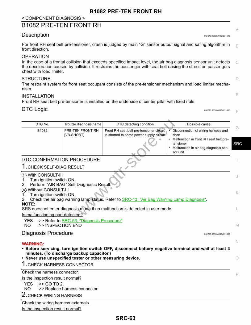
B1082 PRE-TEN FRONT RH
C
D
E
F
G
I
J
K
L
M
A
B
RC
N
O
P
< COMPONENT DIAGNOSIS >
S
B1082 PRE-TEN FRONT RHDescription INFOID:0000000004031636
For front RH seat belt pre-tensioner, crash is judged by main “G” sensor output signal and safing algorithm infront direction.
OPERATIONIn the case of a frontal collision that exceeds specified impact level, the air bag diagnosis sensor unit detectsthe deceleration caused by collision. It restrains the passenger with seat belt easing the stress on passengerschest with load limiter.
STRUCTUREThe restraint system for front seat occupant consists of the pre-tensioner mechanism and load limiter mecha-nism.
INSTALLATIONFront RH seat belt pre-tensioner is installed on the underside of center pillar with fixed nuts.
DTC Logic INFOID:0000000004031637
DTC CONFIRMATION PROCEDURE1.CHECK SELF-DIAG RESULT
With CONSULT-III1. Turn ignition switch ON.2. Perform “AIR BAG” Self Diagnostic Result.
Without CONSULT-III1. Turn ignition switch ON.2. Check the air bag warning lamp status. Refer to SRC-13, "Air Bag Warning Lamp Diagnosis".NOTE:SRS does not enter diagnosis mode if no malfunction is detected in user mode.Is malfunctioning part detected?YES >> Refer to SRC-63, "Diagnosis Procedure".NO >> INSPECTION END
Diagnosis Procedure INFOID:0000000004031638
WARNING:• Before servicing, turn ignition switch OFF, disconnect battery negative terminal and wait at least 3
minutes. (To discharge backup capacitor.)• Never use unspecified tester or other measuring device. 1.CHECK HARNESS CONNECTOR
Check the harness connector.Is the inspection result normal?YES >> GO TO 2.NO >> Replace harness connector.
2.CHECK WIRING HARNESS
Check the wiring harness externals.Is the inspection result normal?
DTC No. Trouble diagnosis name DTC detecting condition Possible cause
B1082 PRE-TEN FRONT RH [VB-SHORT]
Front RH seat belt pre-tensioner circuit is shorted to some power supply circuit
• Disconnection of wiring harness and short
• Malfunction in front RH seat belt pre-tensioner
• Malfunction in air bag diagnosis sen-sor unit
www.gtr-
store
.eu
SRC-63

B1082 PRE-TEN FRONT RH
< COMPONENT DIAGNOSIS >YES >> GO TO 3.NO >> Replace wiring harness.3.REPLACE FRONT SEAT BELT PRE-TENSIONER
1. Replace front RH seat belt pre-tensioner. Refer to SB-6, "SEAT BELT RETRACTOR : Exploded View".2. Perform DTC confirmation procedure. Refer to SRC-63, "DTC Logic".Is DTC detected?YES >> GO TO 4.NO >> INSPECTION END
4.REPLACE AIR BAG DIAGNOSIS SENSOR UNIT
1. Replace air bag diagnosis sensor unit. Refer to SR-19, "Exploded View".2. Perform DTC confirmation procedure. Refer to SRC-63, "DTC Logic".Is DTC detected?YES >> GO TO 1.NO >> INSPECTION END
www.gtr-
store
.eu
SRC-64

B1083 PRE-TEN FRONT RH
C
D
E
F
G
I
J
K
L
M
A
B
RC
N
O
P
< COMPONENT DIAGNOSIS >
S
B1083 PRE-TEN FRONT RHDescription INFOID:0000000004031639
For front RH seat belt pre-tensioner, crash is judged by main “G” sensor output signal and safing algorithm infront direction.
OPERATIONIn the case of a frontal collision that exceeds specified impact level, the air bag diagnosis sensor unit detectsthe deceleration caused by collision. It restrains the passenger with seat belt easing the stress on passengerschest with load limiter.
STRUCTUREThe restraint system for front seat occupant consists of the pre-tensioner mechanism and load limiter mecha-nism.
INSTALLATIONFront RH seat belt pre-tensioner is installed on the underside of center pillar with fixed nuts.
DTC Logic INFOID:0000000004031640
DTC CONFIRMATION PROCEDURE1.CHECK SELF-DIAG RESULT
With CONSULT-III1. Turn ignition switch ON.2. Perform “AIR BAG” Self Diagnostic Result.
Without CONSULT-III1. Turn ignition switch ON.2. Check the air bag warning lamp status. Refer to SRC-13, "Air Bag Warning Lamp Diagnosis".NOTE:SRS does not enter diagnosis mode if no malfunction is detected in user mode.Is malfunctioning part detected?YES >> Refer to SRC-65, "Diagnosis Procedure".NO >> INSPECTION END
Diagnosis Procedure INFOID:0000000004031641
WARNING:• Before servicing, turn ignition switch OFF, disconnect battery negative terminal and wait at least 3
minutes. (To discharge backup capacitor.)• Never use unspecified tester or other measuring device. 1.CHECK HARNESS CONNECTOR
Check the harness connector.Is the inspection result normal?YES >> GO TO 2.NO >> Replace harness connector.
2.CHECK WIRING HARNESS
Check the wiring harness externals.Is the inspection result normal?
DTC No. Trouble diagnosis name DTC detecting condition Possible cause
B1083 PRE-TEN FRONT RH [GND-SHORT]
Front RH seat belt pre-tensioner circuit is shorted to ground
• Disconnection of wiring harness and short
• Malfunction in front RH seat belt pre-tensioner
• Malfunction in air bag diagnosis sen-sor unit
www.gtr-
store
.eu
SRC-65

B1083 PRE-TEN FRONT RH
< COMPONENT DIAGNOSIS >YES >> GO TO 3. NO >> Replace wiring harness.3.REPLACE FRONT SEAT BELT PRE-TENSIONER
1. Replace front RH seat belt pre-tensioner. Refer to SB-6, "SEAT BELT RETRACTOR : Exploded View".2. Perform DTC confirmation procedure. Refer to SRC-65, "DTC Logic".Is DTC detected?YES >> GO TO 4. NO >> INSPECTION END
4.REPLACE AIR BAG DIAGNOSIS SENSOR UNIT
1. Replace air bag diagnosis sensor unit. Refer to SR-19, "Exploded View".2. Perform DTC confirmation procedure. Refer to SRC-65, "DTC Logic".Is DTC detected?YES >> GO TO 1. NO >> INSPECTION END
www.gtr-
store
.eu
SRC-66

B1084 PRE-TEN FRONT RH
C
D
E
F
G
I
J
K
L
M
A
B
RC
N
O
P
< COMPONENT DIAGNOSIS >
S
B1084 PRE-TEN FRONT RHDescription INFOID:0000000004031642
For front RH seat belt pre-tensioner, crash is judged by main “G” sensor output signal and safing algorithm infront direction.
OPERATIONIn the case of a frontal collision that exceeds specified impact level, the air bag diagnosis sensor unit detectsthe deceleration caused by collision. It restrains the passenger with seat belt easing the stress on passengerschest with load limiter.
STRUCTUREThe restraint system for front seat occupant consists of the pre-tensioner mechanism and load limiter mecha-nism.
INSTALLATIONFront RH seat belt pre-tensioner is installed on the underside of center pillar with fixed nuts.
DTC Logic INFOID:0000000004031643
DTC CONFIRMATION PROCEDURE1.CHECK SELF-DIAG RESULT
With CONSULT-III1. Turn ignition switch ON.2. Perform “AIR BAG” Self Diagnostic Result.
Without CONSULT-III1. Turn ignition switch ON.2. Check the air bag warning lamp status. Refer to SRC-13, "Air Bag Warning Lamp Diagnosis".NOTE:SRS does not enter diagnosis mode if no malfunction is detected in user mode.Is malfunctioning part detected?YES >> Refer to SRC-67, "Diagnosis Procedure".NO >> INSPECTION END
Diagnosis Procedure INFOID:0000000004031644
WARNING:• Before servicing, turn ignition switch OFF, disconnect battery negative terminal and wait at least 3
minutes. (To discharge backup capacitor.)• Never use unspecified tester or other measuring device.1.CHECK HARNESS CONNECTOR
Check the harness connector.Is the inspection result normal?YES >> GO TO 2.NO >> Replace harness connector.
2.CHECK WIRING HARNESS
Check the wiring harness externals.Is the inspection result normal?
DTC No. Trouble diagnosis name DTC detecting condition Possible cause
B1084 PRE-TEN FRONT RH [SHORT]
Front RH seat belt pre-tensioner circuit are shorted to each other
• Disconnection of wiring harness and short
• Malfunction in front RH seat belt pre-tensioner
• Malfunction in air bag diagnosis sen-sor unit
www.gtr-
store
.eu
SRC-67
B1084 PRE-TEN FRONT RH
< COMPONENT DIAGNOSIS >YES >> GO TO 3. NO >> Replace wiring harness.3.REPLACE FRONT SEAT BELT PRE-TENSIONER
1. Replace front RH seat belt pre-tensioner. Refer to SB-6, "SEAT BELT RETRACTOR : Exploded View".2. Perform DTC confirmation procedure. Refer to SRC-67, "DTC Logic".Is DTC detected?YES >> GO TO 4. NO >> INSPECTION END
4.REPLACE AIR BAG DIAGNOSIS SENSOR UNIT
1. Replace air bag diagnosis sensor unit. Refer to SR-19, "Exploded View".2. Perform DTC confirmation procedure. Refer to SRC-67, "DTC Logic".Is DTC detected?YES >> GO TO 1. NO >> INSPECTION END
www.gtr-
store
.eu
SRC-68

B1086 PRE-TEN FRONT LH
C
D
E
F
G
I
J
K
L
M
A
B
RC
N
O
P
< COMPONENT DIAGNOSIS >
S
B1086 PRE-TEN FRONT LHDescription INFOID:0000000004031645
For front LH seat belt pre-tensioner, crash is judged by main “G” sensor output signal and safing algorithm infront direction.
OPERATIONIn the case of a frontal collision that exceeds specified impact level, the air bag diagnosis sensor unit detectsthe deceleration caused by collision. It restrains the passenger with seat belt easing the stress on passengerschest with load limiter.
STRUCTUREThe restraint system for front seat occupant consists of the pre-tensioner mechanism and load limiter mecha-nism.
INSTALLATIONFront LH seat belt pre-tensioner is installed on the underside of center pillar with fixed nuts.
DTC Logic INFOID:0000000004031646
DTC CONFIRMATION PROCEDURE1.CHECK SELF-DIAG RESULT
With CONSULT-III1. Turn ignition switch ON.2. Perform “AIR BAG” Self Diagnostic Result.
Without CONSULT-III1. Turn ignition switch ON.2. Check the air bag warning lamp status. Refer to SRC-13, "Air Bag Warning Lamp Diagnosis".NOTE:SRS does not enter diagnosis mode if no malfunction is detected in user mode.Is malfunctioning part detected?YES >> Refer to SRC-69, "Diagnosis Procedure".NO >> INSPECTION END
Diagnosis Procedure INFOID:0000000004031647
WARNING:• Before servicing, turn ignition switch OFF, disconnect battery negative terminal and wait at least 3
minutes. (To discharge backup capacitor.)• Never use unspecified tester or other measuring device.1.CHECK HARNESS CONNECTOR
Check the harness connector.Is the inspection result normal?YES >> GO TO 2.NO >> Replace harness connector.
2.CHECK WIRING HARNESS
Check the wiring harness externals.Is the inspection result normal?
DTC No. Trouble diagnosis name DTC detecting condition Possible cause
B1086 PRE-TEN FRONT LH [OPEN]
Front LH seat belt pre-tensioner circuit is open
• Disconnection of wiring harness and open
• Malfunction in front LH seat belt pre-tensioner
• Malfunction in air bag diagnosis sen-sor unit
www.gtr-
store
.eu
SRC-69

B1086 PRE-TEN FRONT LH
< COMPONENT DIAGNOSIS >YES >> GO TO 3. NO >> Replace wiring harness.3.REPLACE FRONT SEAT BELT PRE-TENSIONER
1. Replace front LH seat belt pre-tensioner. Refer to SB-6, "SEAT BELT RETRACTOR : Exploded View".2. Perform DTC confirmation procedure. Refer to SRC-69, "DTC Logic".Is DTC detected?YES >> GO TO 1. NO >> INSPECTION END
4.REPLACE AIR BAG DIAGNOSIS SENSOR UNIT
1. Replace air bag diagnosis sensor unit. Refer to SR-19, "Exploded View".2. Perform DTC confirmation procedure. Refer to SRC-69, "DTC Logic".Is DTC detected?YES >> GO TO 1. NO >> INSPECTION END
www.gtr-
store
.eu
SRC-70
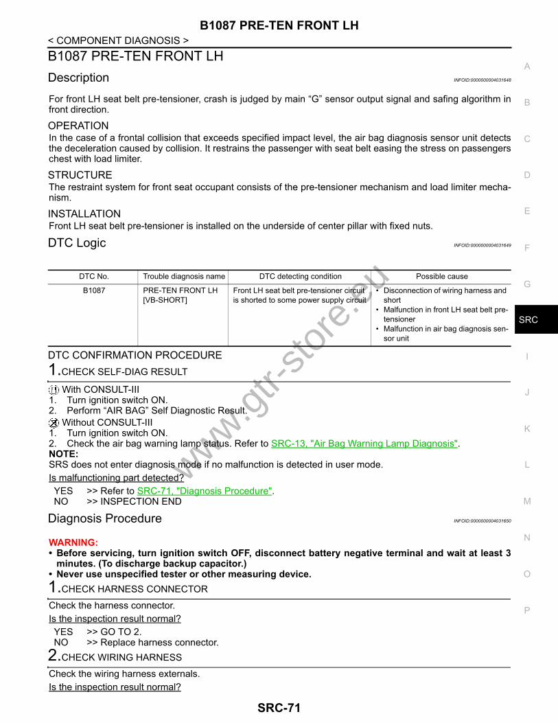
B1087 PRE-TEN FRONT LH
C
D
E
F
G
I
J
K
L
M
A
B
RC
N
O
P
< COMPONENT DIAGNOSIS >
S
B1087 PRE-TEN FRONT LHDescription INFOID:0000000004031648
For front LH seat belt pre-tensioner, crash is judged by main “G” sensor output signal and safing algorithm infront direction.
OPERATIONIn the case of a frontal collision that exceeds specified impact level, the air bag diagnosis sensor unit detectsthe deceleration caused by collision. It restrains the passenger with seat belt easing the stress on passengerschest with load limiter.
STRUCTUREThe restraint system for front seat occupant consists of the pre-tensioner mechanism and load limiter mecha-nism.
INSTALLATIONFront LH seat belt pre-tensioner is installed on the underside of center pillar with fixed nuts.
DTC Logic INFOID:0000000004031649
DTC CONFIRMATION PROCEDURE1.CHECK SELF-DIAG RESULT
With CONSULT-III1. Turn ignition switch ON.2. Perform “AIR BAG” Self Diagnostic Result.
Without CONSULT-III1. Turn ignition switch ON.2. Check the air bag warning lamp status. Refer to SRC-13, "Air Bag Warning Lamp Diagnosis".NOTE:SRS does not enter diagnosis mode if no malfunction is detected in user mode.Is malfunctioning part detected?YES >> Refer to SRC-71, "Diagnosis Procedure".NO >> INSPECTION END
Diagnosis Procedure INFOID:0000000004031650
WARNING:• Before servicing, turn ignition switch OFF, disconnect battery negative terminal and wait at least 3
minutes. (To discharge backup capacitor.)• Never use unspecified tester or other measuring device.1.CHECK HARNESS CONNECTOR
Check the harness connector.Is the inspection result normal?YES >> GO TO 2.NO >> Replace harness connector.
2.CHECK WIRING HARNESS
Check the wiring harness externals.Is the inspection result normal?
DTC No. Trouble diagnosis name DTC detecting condition Possible cause
B1087 PRE-TEN FRONT LH[VB-SHORT]
Front LH seat belt pre-tensioner circuit is shorted to some power supply circuit
• Disconnection of wiring harness and short
• Malfunction in front LH seat belt pre-tensioner
• Malfunction in air bag diagnosis sen-sor unit
www.gtr-
store
.eu
SRC-71
B1087 PRE-TEN FRONT LH
< COMPONENT DIAGNOSIS >YES >> GO TO 3. NO >> Replace wiring harness.3.REPLACE FRONT SEAT BELT PRE-TENSIONER
1. Replace front LH seat belt pre-tensioner. Refer to SB-6, "SEAT BELT RETRACTOR : Exploded View".2. Perform DTC confirmation procedure. Refer to SRC-71, "DTC Logic".Is DTC detected?YES >> GO TO 4. NO >> INSPECTION END
4.REPLACE AIR BAG DIAGNOSIS SENSOR UNIT
1. Replace air bag diagnosis sensor unit. Refer to SR-19, "Exploded View".2. Perform DTC confirmation procedure. Refer to SRC-71, "DTC Logic".Is DTC detected?YES >> GO TO 1. NO >> INSPECTION END
www.gtr-
store
.eu
SRC-72

B1088 PRE-TEN FRONT LH
C
D
E
F
G
I
J
K
L
M
A
B
RC
N
O
P
< COMPONENT DIAGNOSIS >
S
B1088 PRE-TEN FRONT LHDescription INFOID:0000000004031651
For front LH seat belt pre-tensioner, crash is judged by main “G” sensor output signal and safing algorithm infront direction.
OPERATIONIn the case of a frontal collision that exceeds specified impact level, the air bag diagnosis sensor unit detectsthe deceleration caused by collision. It restrains the passenger with seat belt easing the stress on passengerschest with load limiter.
STRUCTUREThe restraint system for front seat occupant consists of the pre-tensioner mechanism and load limiter mecha-nism.
INSTALLATIONFront LH seat belt pre-tensioner is installed on the underside of center pillar with fixed nuts.
DTC Logic INFOID:0000000004031652
DTC CONFIRMATION PROCEDURE1.CHECK SELF-DIAG RESULT
With CONSULT-III1. Turn ignition switch ON.2. Perform “AIR BAG” Self Diagnostic Result.
Without CONSULT-III1. Turn ignition switch ON.2. Check the air bag warning lamp status. Refer to SRC-13, "Air Bag Warning Lamp Diagnosis".NOTE:SRS does not enter diagnosis mode if no malfunction is detected in user mode.Is malfunctioning part detected?YES >> Refer to SRC-73, "Diagnosis Procedure".NO >> INSPECTION END
Diagnosis Procedure INFOID:0000000004031653
WARNING:• Before servicing, turn ignition switch OFF, disconnect battery negative terminal and wait at least 3
minutes. (To discharge backup capacitor.)• Never use unspecified tester or other measuring device.1.CHECK HARNESS CONNECTOR
Check the harness connector.Is the inspection result normal?YES >> GO TO 2.NO >> Replace harness connector.
2.CHECK WIRING HARNESS
Check the wiring harness externals.Is the inspection result normal?
DTC No. Trouble diagnosis name DTC detecting condition Possible cause
B1088 PRE-TEN FRONT LH [GND-SHORT]
Front LH seat belt pre-tensioner circuit is shorted to ground
• Disconnection of wiring harness and short
• Malfunction in front LH seat belt pre-tensioner
• Malfunction in air bag diagnosis sen-sor unit
www.gtr-
store
.eu
SRC-73

B1088 PRE-TEN FRONT LH
< COMPONENT DIAGNOSIS >YES >> GO TO 3. NO >> Replace wiring harness.3.REPLACE FRONT SEAT BELT PRE-TENSIONER
1. Replace front LH seat belt pre-tensioner. Refer to SB-6, "SEAT BELT RETRACTOR : Exploded View".2. Perform DTC confirmation procedure. Refer to SRC-73, "DTC Logic".Is DTC detected?YES >> GO TO 4. NO >> INSPECTION END
4.REPLACE AIR BAG DIAGNOSIS SENSOR UNIT
1. Replace air bag diagnosis sensor unit. Refer to SR-19, "Exploded View".2. Perform DTC confirmation procedure. Refer to SRC-73, "DTC Logic".Is DTC detected?YES >> GO TO 1. NO >> INSPECTION END
www.gtr-
store
.eu
SRC-74

B1089 PRE-TEN FRONT LH
C
D
E
F
G
I
J
K
L
M
A
B
RC
N
O
P
< COMPONENT DIAGNOSIS >
S
B1089 PRE-TEN FRONT LHDescription INFOID:0000000004031654
For front LH seat belt pre-tensioner, crash is judged by main “G” sensor output signal and safing algorithm infront direction.
OPERATIONIn the case of a frontal collision that exceeds specified impact level, the air bag diagnosis sensor unit detectsthe deceleration caused by collision. It restrains the passenger with seat belt easing the stress on passengerschest with load limiter.
STRUCTUREThe restraint system for front seat occupant consists of the pre-tensioner mechanism and load limiter mecha-nism.
INSTALLATIONFront LH seat belt pre-tensioner is installed on the underside of center pillar with fixed nuts.
DTC Logic INFOID:0000000004031655
DTC CONFIRMATION PROCEDURE1.CHECK SELF-DIAG RESULT
With CONSULT-III1. Turn ignition switch ON.2. Perform “AIR BAG” Self Diagnostic Result.
Without CONSULT-III1. Turn ignition switch ON.2. Check the air bag warning lamp status. Refer to SRC-13, "Air Bag Warning Lamp Diagnosis".NOTE:SRS does not enter diagnosis mode if no malfunction is detected in user mode.Is malfunctioning part detected?YES >> Refer to SRC-75, "Diagnosis Procedure".NO >> INSPECTION END
Diagnosis Procedure INFOID:0000000004031656
WARNING:• Before servicing, turn ignition switch OFF, disconnect battery negative terminal and wait at least 3
minutes. (To discharge backup capacitor.)• Never use unspecified tester or other measuring device.1.CHECK HARNESS CONNECTOR
Check the harness connector.Is the inspection result normal?YES >> GO TO 2.NO >> Replace harness connector.
2.CHECK WIRING HARNESS
Check the wiring harness externals.Is the inspection result normal?
DTC No. Trouble diagnosis name DTC detecting condition Possible cause
B1089 PRE-TEN FRONT LH [SHORT]
Front LH seat belt pre-tensioner circuit are shorted to each other
• Disconnection of wiring harness and short
• Malfunction in front LH seat belt pre-tensioner
• Malfunction in air bag diagnosis sen-sor unit
www.gtr-
store
.eu
SRC-75

B1089 PRE-TEN FRONT LH
< COMPONENT DIAGNOSIS >YES >> GO TO 3. NO >> Replace wiring harness.3.REPLACE FRONT SEAT BELT PRE-TENSIONER
1. Replace front LH seat belt pre-tensioner. Refer to SB-6, "SEAT BELT RETRACTOR : Exploded View".2. Perform DTC confirmation procedure. Refer to SRC-75, "DTC Logic".Is DTC detected?YES >> GO TO 4. NO >> INSPECTION END
4.REPLACE AIR BAG DIAGNOSIS SENSOR UNIT
1. Replace air bag diagnosis sensor unit. Refer to SR-19, "Exploded View".2. Perform DTC confirmation procedure. Refer to SRC-75, "DTC Logic".Is DTC detected?YES >> GO TO 1. NO >> INSPECTION END
www.gtr-
store
.eu
SRC-76
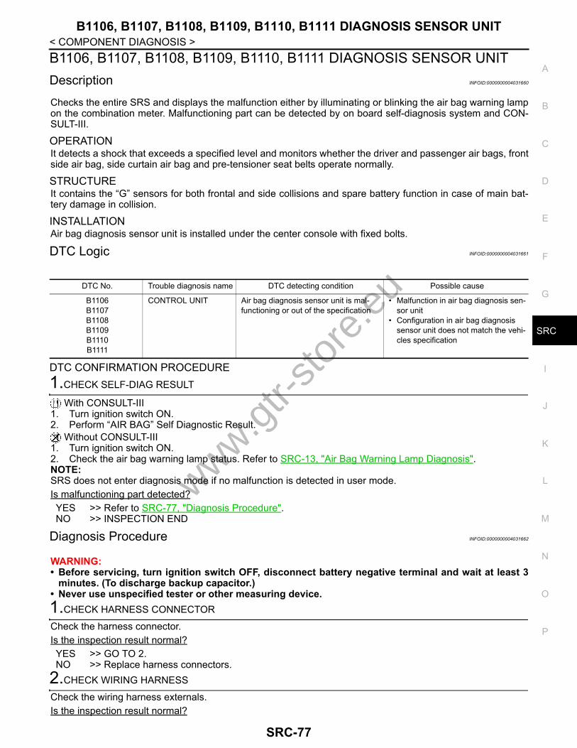
B1106, B1107, B1108, B1109, B1110, B1111 DIAGNOSIS SENSOR UNIT
C
D
E
F
G
I
J
K
L
M
A
B
RC
N
O
P
< COMPONENT DIAGNOSIS >
S
B1106, B1107, B1108, B1109, B1110, B1111 DIAGNOSIS SENSOR UNITDescription INFOID:0000000004031660
Checks the entire SRS and displays the malfunction either by illuminating or blinking the air bag warning lampon the combination meter. Malfunctioning part can be detected by on board self-diagnosis system and CON-SULT-III.
OPERATIONIt detects a shock that exceeds a specified level and monitors whether the driver and passenger air bags, frontside air bag, side curtain air bag and pre-tensioner seat belts operate normally.
STRUCTUREIt contains the “G” sensors for both frontal and side collisions and spare battery function in case of main bat-tery damage in collision.
INSTALLATIONAir bag diagnosis sensor unit is installed under the center console with fixed bolts.
DTC Logic INFOID:0000000004031661
DTC CONFIRMATION PROCEDURE1.CHECK SELF-DIAG RESULT
With CONSULT-III1. Turn ignition switch ON.2. Perform “AIR BAG” Self Diagnostic Result.
Without CONSULT-III1. Turn ignition switch ON.2. Check the air bag warning lamp status. Refer to SRC-13, "Air Bag Warning Lamp Diagnosis".NOTE:SRS does not enter diagnosis mode if no malfunction is detected in user mode.Is malfunctioning part detected?YES >> Refer to SRC-77, "Diagnosis Procedure".NO >> INSPECTION END
Diagnosis Procedure INFOID:0000000004031662
WARNING:• Before servicing, turn ignition switch OFF, disconnect battery negative terminal and wait at least 3
minutes. (To discharge backup capacitor.)• Never use unspecified tester or other measuring device. 1.CHECK HARNESS CONNECTOR
Check the harness connector.Is the inspection result normal?YES >> GO TO 2.NO >> Replace harness connectors.
2.CHECK WIRING HARNESS
Check the wiring harness externals.Is the inspection result normal?
DTC No. Trouble diagnosis name DTC detecting condition Possible cause
B1106B1107B1108B1109B1110B1111
CONTROL UNIT Air bag diagnosis sensor unit is mal-functioning or out of the specification
• Malfunction in air bag diagnosis sen-sor unit
• Configuration in air bag diagnosis sensor unit does not match the vehi-cles specification
www.gtr-
store
.eu
SRC-77

B1106, B1107, B1108, B1109, B1110, B1111 DIAGNOSIS SENSOR UNIT
< COMPONENT DIAGNOSIS >YES >> GO TO 3.NO >> Replace wiring harness.3.REPLACE AIR BAG DIAGNOSIS SENSOR UNIT
1. Replace air bag diagnosis sensor unit. Refer to SR-19, "Exploded View".2. Perform DTC confirmation procedure. Refer to SRC-77, "DTC Logic".Is DTC detected?YES >> GO TO 1. NO >> INSPECTION END
www.gtr-
store
.eu
SRC-78

B1113, B1114 SATELLITE SENS RH
C
D
E
F
G
I
J
K
L
M
A
B
RC
N
O
P
< COMPONENT DIAGNOSIS >
S
B1113, B1114 SATELLITE SENS RHDescription INFOID:0000000004031663
Main “G” sensor generates signal voltage, when it detects deceleration beyond the specified level by vehicleside collision.
OPERATIONWhen air bag diagnosis sensor unit defines both signal voltage of the “G” sensor and the safing algorithm tobe that of collision which exceeds a specified level, the driving circuit switches on and feeds the electric ignitorof both the front side air bag and side curtain air bag.
STRUCTUREIntegrated type of the “G” sensor element for side collision with output terminals for signal voltage.
INSTALLATIONRH satellite sensor is installed at the underside of center pillar with fixed nuts.
DTC Logic INFOID:0000000004031664
DTC CONFIRMATION PROCEDURE1.CHECK SELF-DIAG RESULT
With CONSULT-III1. Turn ignition switch ON.2. Perform “AIR BAG” Self Diagnostic Result.
Without CONSULT-III1. Turn ignition switch ON.2. Check the air bag warning lamp status. Refer to SRC-13, "Air Bag Warning Lamp Diagnosis".NOTE:SRS does not enter diagnosis mode if no malfunction is detected in user mode.Is malfunctioning part detected?YES >> Refer to SRC-79, "Diagnosis Procedure".NO >> INSPECTION END
Diagnosis Procedure INFOID:0000000004031665
WARNING:• Before servicing, turn ignition switch OFF, disconnect battery negative terminal and wait at least 3
minutes. (To discharge backup capacitor.)• Never use unspecified tester or other measuring device. 1.CHECK HARNESS CONNECTOR
Check the harness connector.Is the inspection result normal?YES >> GO TO 2.NO >> Replace harness connector.
2.CHECK WIRING HARNESS
Check the wiring harness externals.Is the inspection result normal?YES >> GO TO 3. NO >> Replace wiring harness.
DTC No. Trouble diagnosis name DTC detecting condition Possible cause
B1113B1114
SATELLITE SENS RH [UNIT FAIL]
RH satellite sensor is malfunctioning • Disconnection of wiring harness• Malfunction in RH satellite sensor• Malfunction in air bag diagnosis sen-
sor unit
www.gtr-
store
.eu
SRC-79
B1113, B1114 SATELLITE SENS RH
< COMPONENT DIAGNOSIS >3.REPLACE SATELLITE SENSOR
1. Replace RH satellite sensor. Refer to SR-17, "Exploded View".2. Perform DTC confirmation procedure. Refer to SRC-79, "DTC Logic".Is DTC detected?YES >> GO TO 4. NO >> INSPECTION END
4.REPLACE AIR BAG DIAGNOSIS SENSOR UNIT
1. Replace air bag diagnosis sensor unit. Refer to SR-19, "Exploded View".2. Perform DTC confirmation procedure. Refer to SRC-79, "DTC Logic".Is DTC detected?YES >> GO TO 1. NO >> INSPECTION END
www.gtr-
store
.eu
SRC-80
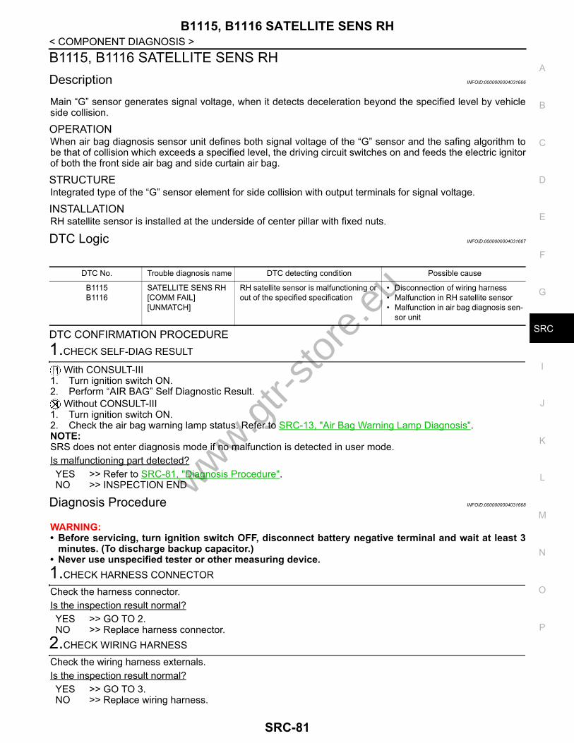
B1115, B1116 SATELLITE SENS RH
C
D
E
F
G
I
J
K
L
M
A
B
RC
N
O
P
< COMPONENT DIAGNOSIS >
S
B1115, B1116 SATELLITE SENS RHDescription INFOID:0000000004031666
Main “G” sensor generates signal voltage, when it detects deceleration beyond the specified level by vehicleside collision.
OPERATIONWhen air bag diagnosis sensor unit defines both signal voltage of the “G” sensor and the safing algorithm tobe that of collision which exceeds a specified level, the driving circuit switches on and feeds the electric ignitorof both the front side air bag and side curtain air bag.
STRUCTUREIntegrated type of the “G” sensor element for side collision with output terminals for signal voltage.
INSTALLATIONRH satellite sensor is installed at the underside of center pillar with fixed nuts.
DTC Logic INFOID:0000000004031667
DTC CONFIRMATION PROCEDURE1.CHECK SELF-DIAG RESULT
With CONSULT-III1. Turn ignition switch ON.2. Perform “AIR BAG” Self Diagnostic Result.
Without CONSULT-III1. Turn ignition switch ON.2. Check the air bag warning lamp status. Refer to SRC-13, "Air Bag Warning Lamp Diagnosis".NOTE:SRS does not enter diagnosis mode if no malfunction is detected in user mode.Is malfunctioning part detected?YES >> Refer to SRC-81, "Diagnosis Procedure".NO >> INSPECTION END
Diagnosis Procedure INFOID:0000000004031668
WARNING:• Before servicing, turn ignition switch OFF, disconnect battery negative terminal and wait at least 3
minutes. (To discharge backup capacitor.)• Never use unspecified tester or other measuring device.1.CHECK HARNESS CONNECTOR
Check the harness connector.Is the inspection result normal?YES >> GO TO 2.NO >> Replace harness connector.
2.CHECK WIRING HARNESS
Check the wiring harness externals.Is the inspection result normal?YES >> GO TO 3. NO >> Replace wiring harness.
DTC No. Trouble diagnosis name DTC detecting condition Possible cause
B1115B1116
SATELLITE SENS RH [COMM FAIL][UNMATCH]
RH satellite sensor is malfunctioning or out of the specified specification
• Disconnection of wiring harness• Malfunction in RH satellite sensor• Malfunction in air bag diagnosis sen-
sor unit
www.gtr-
store
.eu
SRC-81

B1115, B1116 SATELLITE SENS RH
< COMPONENT DIAGNOSIS >3.REPLACE SATELLITE SENSOR
1. Replace RH satellite sensor. Refer to SR-17, "Exploded View".2. Perform DTC confirmation procedure. Refer to SRC-81, "DTC Logic".Is DTC detected?YES >> GO TO 4. NO >> INSPECTION END
4.REPLACE AIR BAG DIAGNOSIS SENSOR UNIT
1. Replace air bag diagnosis sensor unit. Refer to SR-19, "Exploded View".2. Perform DTC confirmation procedure. Refer to SRC-81, "DTC Logic".Is DTC detected?YES >> GO TO 1. NO >> INSPECTION END
www.gtr-
store
.eu
SRC-82

B1118, B1119 SATELLITE SENS LH
C
D
E
F
G
I
J
K
L
M
A
B
RC
N
O
P
< COMPONENT DIAGNOSIS >
S
B1118, B1119 SATELLITE SENS LHDescription INFOID:0000000004031669
Main “G” sensor generates signal voltage, when it detects deceleration beyond the specified level by vehicleside collision.
OPERATIONWhen air bag diagnosis sensor unit defines both signal voltage of the “G” sensor and the safing algorithm tobe that of collision which exceeds a specified level, the driving circuit switches on and feeds the electric ignitorof both the front side air bag and side curtain air bag.
STRUCTUREIntegrated type of the “G” sensor element for side collision with output terminals for signal voltage.
INSTALLATIONLH satellite sensor is installed at the underside of center pillar with fixed nuts.
DTC Logic INFOID:0000000004031670
DTC CONFIRMATION PROCEDURE1.CHECK SELF-DIAG RESULT
With CONSULT-III1. Turn ignition switch ON.2. Perform “AIR BAG” Self Diagnostic Result.
Without CONSULT-III1. Turn ignition switch ON.2. Check the air bag warning lamp status. Refer to SRC-13, "Air Bag Warning Lamp Diagnosis".NOTE:SRS does not enter diagnosis mode if no malfunction is detected in user mode.Is malfunctioning part detected?YES >> Refer to SRC-83, "Diagnosis Procedure".NO >> INSPECTION END
Diagnosis Procedure INFOID:0000000004031671
WARNING:• Before servicing, turn ignition switch OFF, disconnect battery negative terminal and wait at least 3
minutes. (To discharge backup capacitor.)• Never use unspecified tester or other measuring device. 1.CHECK HARNESS CONNECTOR
Check the harness connector.Is the inspection result normal?YES >> GO TO 2.NO >> Replace harness connector.
2.CHECK WIRING HARNESS
Check the wiring harness externals.Is the inspection result normal?YES >> GO TO 3. NO >> Replace wiring harness.
DTC No. Trouble diagnosis name DTC detecting condition Possible cause
B1118B1119
SATELLITE SENS LH[UNIT FAIL]
LH satellite sensor is malfunctioning • Disconnection of wiring harness• Malfunction in LH satellite sensor• Malfunction in air bag diagnosis sen-
sor unit
www.gtr-
store
.eu
SRC-83

B1118, B1119 SATELLITE SENS LH
< COMPONENT DIAGNOSIS >3.REPLACE SATELLITE SENSOR
1. Replace LH satellite sensor. Refer to SR-17, "Exploded View".2. Perform DTC confirmation procedure. Refer to SRC-83, "DTC Logic"Is DTC detected?YES >> GO TO 4. NO >> INSPECTION END
4.REPLACE AIR BAG DIAGNOSIS SENSOR UNIT
1. Replace air bag diagnosis sensor unit. Refer to SR-19, "Exploded View".2. Perform DTC confirmation procedure. Refer to SRC-83, "DTC Logic".Is DTC detected?YES >> GO TO 1. NO >> INSPECTION END
www.gtr-
store
.eu
SRC-84

B1120, B1121 SATELLITE SENS LH
C
D
E
F
G
I
J
K
L
M
A
B
RC
N
O
P
< COMPONENT DIAGNOSIS >
S
B1120, B1121 SATELLITE SENS LHDescription INFOID:0000000004031672
Main “G” sensor generates signal voltage, when it detects deceleration beyond the specified level by vehicleside collision.
OPERATIONWhen air bag diagnosis sensor unit defines both signal voltage of the “G” sensor and the safing algorithm tobe that of collision which exceeds a specified level, the driving circuit switches on and feeds the electric ignitorof both the front side air bag and side curtain air bag.
STRUCTUREIntegrated type of the “G” sensor element for side collision with output terminals for signal voltage.
INSTALLATIONLH satellite sensor is installed at the underside of center pillar with fixed nuts.
DTC Logic INFOID:0000000004031673
DTC CONFIRMATION PROCEDURE1.CHECK SELF-DIAG RESULT
With CONSULT-III1. Turn ignition switch ON.2. Perform “AIR BAG” Self Diagnostic Result.
Without CONSULT-III1. Turn ignition switch ON.2. Check the air bag warning lamp status. Refer to SRC-13, "Air Bag Warning Lamp Diagnosis".NOTE:SRS does not enter diagnosis mode if no malfunction is detected in user mode.Is malfunctioning part detected?YES >> Refer to SRC-85, "Diagnosis Procedure".NO >> INSPECTION END
Diagnosis Procedure INFOID:0000000004031674
WARNING:• Before servicing, turn ignition switch OFF, disconnect battery negative terminal and wait at least 3
minutes. (To discharge backup capacitor.)• Never use unspecified tester or other measuring device. 1.CHECK HARNESS CONNECTOR
Check the harness connector.Is the inspection result normal?YES >> GO TO 2.NO >> Replace harness connector.
2.CHECK WIRING HARNESS
Check the wiring harness externals.Is the inspection result normal?YES >> GO TO 3. NO >> Replace wiring harness.
DTC No. Trouble diagnosis name DTC detecting condition Possible cause
B1120B1121
SATELLITE SENS LH [COMM FAIL][UNMATCH]
LH satellite sensor is malfunctioning or out of the specified specification
• Disconnection of wiring harness• Malfunction in LH satellite sensor• Malfunction in air bag diagnosis sen-
sor unit
www.gtr-
store
.eu
SRC-85

B1120, B1121 SATELLITE SENS LH
< COMPONENT DIAGNOSIS >3.REPLACE SATELLITE SENSOR
1. Replace LH satellite sensor. Refer to SR-17, "Exploded View".2. Perform DTC confirmation procedure. Refer to SRC-85, "DTC Logic".Is DTC detected?YES >> GO TO 4. NO >> INSPECTION END
4.REPLACE AIR BAG DIAGNOSIS SENSOR UNIT
1. Replace air bag diagnosis sensor unit. Refer to SR-19, "Exploded View".2. Perform DTC confirmation procedure. Refer to SRC-85, "DTC Logic".Is DTC detected?YES >> GO TO 1. NO >> INSPECTION END
www.gtr-
store
.eu
SRC-86

B1122, B1123, B1124, B1125, B1126, B1127 DIAGNOSIS SENSOR UNIT
C
D
E
F
G
I
J
K
L
M
A
B
RC
N
O
P
< COMPONENT DIAGNOSIS >
S
B1122, B1123, B1124, B1125, B1126, B1127 DIAGNOSIS SENSOR UNITDescription INFOID:0000000004031675
Checks the entire SRS and displays the malfunction either by illuminating or blinking the air bag warning lampon the combination meter. Malfunctioning part can be detected by on board self-diagnosis system and CON-SULT-III.
OPERATIONIt detects a shock that exceeds a specified level and monitors whether the driver and passenger air bags, frontside air bag, side curtain air bag and pre-tensioner seat belts operate normally.
STRUCTUREIt contains the “G” sensors for both frontal and side collisions and spare battery function in case of main bat-tery damage in collision.
INSTALLATIONAir bag diagnosis sensor unit is installed under the center console with fixed bolts.
DTC Logic INFOID:0000000004031676
DTC CONFIRMATION PROCEDURE1.CHECK SELF-DIAG RESULT
With CONSULT-III1. Turn ignition switch ON.2. Perform “AIR BAG” Self Diagnostic Result.
Without CONSULT-III1. Turn ignition switch ON.2. Check the air bag warning lamp status. Refer to SRC-13, "Air Bag Warning Lamp Diagnosis".NOTE:SRS does not enter diagnosis mode if no malfunction is detected in user mode.Is malfunctioning part detected?YES >> Refer to SRC-87, "Diagnosis Procedure".NO >> INSPECTION END
Diagnosis Procedure INFOID:0000000004031677
WARNING:• Before servicing, turn ignition switch OFF, disconnect battery negative terminal and wait at least 3
minutes. (To discharge backup capacitor.)• Never use unspecified tester or other measuring device. 1.CHECK HARNESS CONNECTOR
Check the harness connector.Is the inspection result normal?YES >> GO TO 2.NO >> Replace harness connectors.
2.CHECK WIRING HARNESS
Check the wiring harness externals.Is the inspection result normal?
DTC No. Trouble diagnosis name DTC detecting condition Possible cause
B1122B1123B1124B1125B1126B1127
CONTROL UNIT Air bag diagnosis sensor unit is mal-functioning or out of the specification
• Malfunction in air bag diagnosis sen-sor unit
• Configuration in air bag diagnosis sensor unit does not match the vehi-cles specification
www.gtr-
store
.eu
SRC-87

B1122, B1123, B1124, B1125, B1126, B1127 DIAGNOSIS SENSOR UNIT
< COMPONENT DIAGNOSIS >YES >> GO TO 3.NO >> Replace wiring harness.3.REPLACE AIR BAG DIAGNOSIS SENSOR UNIT
1. Replace air bag diagnosis sensor unit. Refer to SR-19, "Exploded View".2. Perform DTC confirmation procedure. Refer to SRC-87, "DTC Logic".Is DTC detected?YES >> GO TO 1. NO >> INSPECTION END
www.gtr-
store
.eu
SRC-88

B1129 SIDE MODULE RH
C
D
E
F
G
I
J
K
L
M
A
B
RC
N
O
P
< COMPONENT DIAGNOSIS >
S
B1129 SIDE MODULE RHDescription INFOID:0000000004031678
For front RH side air bag module, crash is judged by main “G” sensor output signal (left side: LH satellite sen-sor, right side: RH satellite sensor) and safing algorithm (in air bag diagnosis sensor unit).
OPERATIONIn case of frontal collision whose acceleration exceeds the specified level, the ignition materials are ignited byelectric ignition system. The system burns the gas generating materials resulting in a chemical reaction. Thisgenerates hot gases that flow into the air bag through a filter and expand the bag.
STRUCTUREFront RH side air bag module mainly consists of air bag and inflator that inflates air bag.
INSTALLATIONFront RH side air bag module is installed on the side of front seat back with fixed nuts.
DTC Logic INFOID:0000000004031679
DTC CONFIRMATION PROCEDURE1.CHECK SELF-DIAG RESULT
With CONSULT-III1. Turn ignition switch ON.2. Perform “AIR BAG” Self Diagnostic Result.
Without CONSULT-III1. Turn ignition switch ON.2. Check the air bag warning lamp status.SRC-13, "Air Bag Warning Lamp Diagnosis" NOTE:SRS does not enter diagnosis mode if no malfunction is detected in user mode.Is malfunctioning part detected?YES >> Refer to SRC-89, "Diagnosis Procedure".NO >> INSPECTION END
Diagnosis Procedure INFOID:0000000004031680
WARNING:• Before servicing, turn ignition switch OFF, disconnect battery negative terminal and wait at least 3
minutes. (To discharge backup capacitor.)• Never use unspecified tester or other measuring device. 1.CHECK HARNESS CONNECTOR
Check the harness connector.Is the inspection result normal?YES >> GO TO 2.NO >> Replace harness connector.
2.CHECK WIRING HARNESS
Check the wiring harness externals.Is the inspection result normal?YES >> GO TO 3.
DTC No. Trouble diagnosis name DTC detecting condition Possible cause
B1129 SIDE MODULE RH[OPEN]
Front RH side air bag module circuit is open
• Disconnection of wiring harness and open
• Malfunction in front RH side air bag module
• Malfunction in air bag diagnosis sen-sor unit
www.gtr-
store
.eu
SRC-89

B1129 SIDE MODULE RH
< COMPONENT DIAGNOSIS >NO >> Replace wiring harness.3.REPLACE FRONT SIDE AIR BAG MODULE
1. Replace front RH side air bag module. Refer to SE-29, "Exploded View".2. Perform DTC confirmation procedure. Refer to SRC-89, "DTC Logic".Is DTC detected?YES >> GO TO 4. NO >> INSPECTION END
4.REPLACE AIR BAG DIAGNOSIS SENSOR UNIT
1. Replace air bag diagnosis sensor unit. Refer to SR-19, "Exploded View".2. Perform DTC confirmation procedure. Refer to SRC-89, "DTC Logic".Is DTC detected?YES >> GO TO 1. NO >> INSPECTION END
www.gtr-
store
.eu
SRC-90

B1130 SIDE MODULE RH
C
D
E
F
G
I
J
K
L
M
A
B
RC
N
O
P
< COMPONENT DIAGNOSIS >
S
B1130 SIDE MODULE RHDescription INFOID:0000000004031681
For front RH side air bag module, crash is judged by main “G” sensor output signal (left side: LH satellite sen-sor, right side: RH satellite sensor) and safing algorithm (in air bag diagnosis sensor unit).
OPERATIONIn case of frontal collision whose acceleration exceeds the specified level, the ignition materials are ignited byelectric ignition system. The system burns the gas generating materials resulting in a chemical reaction. Thisgenerates hot gases that flow into the air bag through a filter and expand the bag.
STRUCTUREFront RH side air bag module mainly consists of air bag and inflator that inflates air bag.
INSTALLATIONFront RH side air bag module is installed on the side of front seatback with fixed nuts.
DTC Logic INFOID:0000000004031682
DTC CONFIRMATION PROCEDURE1.CHECK SELF-DIAG RESULT
With CONSULT-III1. Turn ignition switch ON.2. Perform “AIR BAG” Self Diagnostic Result.
Without CONSULT-III1. Turn ignition switch ON.2. Check the air bag warning lamp status. Refer to SRC-13, "Air Bag Warning Lamp Diagnosis".NOTE:SRS does not enter diagnosis mode if no malfunction is detected in user mode.Is malfunctioning part detected?YES >> Refer to SRC-91, "Diagnosis Procedure".NO >> INSPECTION END
Diagnosis Procedure INFOID:0000000004031683
WARNING:• Before servicing, turn ignition switch OFF, disconnect battery negative terminal and wait at least 3
minutes. (To discharge backup capacitor.)• Never use unspecified tester or other measuring device. 1.CHECK HARNESS CONNECTOR
Check the harness connector.Is the inspection result normal?YES >> GO TO 2.NO >> Replace harness connector.
2.CHECK WIRING HARNESS
Check the wiring harness externals.Is the inspection result normal?YES >> GO TO 3.
DTC No. Trouble diagnosis name DTC detecting condition Possible cause
B1130 SIDE MODULE RH [VB-SHORT]
Front RH side air bag module circuit is shorted to some power supply circuit
• Disconnection of wiring harness and short
• Malfunction in front RH side air bag module
• Malfunction in air bag diagnosis sen-sor unit
www.gtr-
store
.eu
SRC-91

B1130 SIDE MODULE RH
< COMPONENT DIAGNOSIS >NO >> Replace wiring harness.3.REPLACE FRONT SIDE AIR BAG MODULE
1. Replace front RH side air bag module. Refer to SE-29, "Exploded View".2. Perform DTC confirmation procedure. Refer to SRC-91, "DTC Logic".Is DTC detected?YES >> GO TO 4. NO >> INSPECTION END
4.REPLACE AIR BAG DIAGNOSIS SENSOR UNIT
1. Replace air bag diagnosis sensor unit. Refer to SR-19, "Exploded View".2. Perform DTC confirmation procedure. Refer to SRC-91, "DTC Logic".Is DTC detected?YES >> GO TO 1. NO >> INSPECTION END
www.gtr-
store
.eu
SRC-92

B1131 SIDE MODULE RH
C
D
E
F
G
I
J
K
L
M
A
B
RC
N
O
P
< COMPONENT DIAGNOSIS >
S
B1131 SIDE MODULE RHDescription INFOID:0000000004031684
For front RH side air bag module, crash is judged by main “G” sensor output signal (left side: LH satellite sen-sor, right side: RH satellite sensor) and safing algorithm (in air bag diagnosis sensor unit).
OPERATIONIn case of frontal collision whose acceleration exceeds the specified level, the ignition materials are ignited byelectric ignition system. The system burns the gas generating materials resulting in a chemical reaction. Thisgenerates hot gases that flow into the air bag through a filter and expand the bag.
STRUCTUREFront RH side air bag module mainly consists of air bag and inflator that inflates air bag.
INSTALLATIONFront RH side air bag module is installed on the side of front seatback with fixed nuts.
DTC Logic INFOID:0000000004031685
DTC CONFIRMATION PROCEDURE1.CHECK SELF-DIAG RESULT
With CONSULT-III1. Turn ignition switch ON.2. Perform “AIR BAG” Self Diagnostic Result.
Without CONSULT-III1. Turn ignition switch ON.2. Check the air bag warning lamp status. Refer to SRC-13, "Air Bag Warning Lamp Diagnosis".NOTE:SRS does not enter diagnosis mode if no malfunction is detected in user mode.Is malfunctioning part detected?YES >> Refer to SRC-93, "Diagnosis Procedure".NO >> INSPECTION END
Diagnosis Procedure INFOID:0000000004031686
WARNING:• Before servicing, turn ignition switch OFF, disconnect battery negative terminal and wait at least 3
minutes. (To discharge backup capacitor.)• Never use unspecified tester or other measuring device. 1.CHECK HARNESS CONNECTOR
Check the harness connector.Is the inspection result normal?YES >> GO TO 2.NO >> Replace harness connector.
2.CHECK WIRING HARNESS
Check the wiring harness externals.Is the inspection result normal?YES >> GO TO 3.
DTC No. Trouble diagnosis name DTC detecting condition Possible cause
B1131 SIDE MODULE RH [GND-SHORT]
Front RH side air bag module circuit is shorted to ground
• Disconnection of wiring harness and short
• Malfunction in front RH side air bag module
• Malfunction in air bag diagnosis sen-sor unit
www.gtr-
store
.eu
SRC-93

B1131 SIDE MODULE RH
< COMPONENT DIAGNOSIS >NO >> Replace wiring harness.3.REPLACE FRONT SIDE AIR BAG MODULE
1. Replace front RH side air bag module. Refer to SE-29, "Exploded View".2. Perform DTC confirmation procedure. Refer to SRC-93, "DTC Logic".Is DTC detected?YES >> GO TO 4. NO >> INSPECTION END
4.REPLACE AIR BAG DIAGNOSIS SENSOR UNIT
1. Replace air bag diagnosis sensor unit. Refer to SR-19, "Exploded View".2. Perform DTC confirmation procedure. Refer to SRC-93, "DTC Logic".Is DTC detected?YES >> GO TO 1. NO >> INSPECTION END
www.gtr-
store
.eu
SRC-94

B1132 SIDE MODULE RH
C
D
E
F
G
I
J
K
L
M
A
B
RC
N
O
P
< COMPONENT DIAGNOSIS >
S
B1132 SIDE MODULE RHDescription INFOID:0000000004031687
For front RH side air bag module, crash is judged by main “G” sensor output signal (left side: LH satellite sen-sor, right side: RH satellite sensor) and safing algorithm (in air bag diagnosis sensor unit).
OPERATIONIn case of frontal collision whose acceleration exceeds the specified level, the ignition materials are ignited byelectric ignition system. The system burns the gas generating materials resulting in a chemical reaction. Thisgenerates hot gases that flow into the air bag through a filter and expand the bag.
STRUCTUREFront RH side air bag module mainly consists of air bag and inflator that inflates air bag.
INSTALLATIONFront RH side air bag module is installed on the side of front seatback with fixed nuts.
DTC Logic INFOID:0000000004031688
DTC CONFIRMATION PROCEDURE1.CHECK SELF-DIAG RESULT
With CONSULT-III1. Turn ignition switch ON.2. Perform “AIR BAG” Self Diagnostic Result.
Without CONSULT-III1. Turn ignition switch ON.2. Check the air bag warning lamp status. Refer to SRC-13, "Air Bag Warning Lamp Diagnosis".NOTE:SRS does not enter diagnosis mode if no malfunction is detected in user mode.Is malfunctioning part detected?YES >> Refer to SRC-95, "Diagnosis Procedure".NO >> INSPECTION END
Diagnosis Procedure INFOID:0000000004031689
WARNING:• Before servicing, turn ignition switch OFF, disconnect battery negative terminal and wait at least 3
minutes. (To discharge backup capacitor.)• Never use unspecified tester or other measuring device.1.CHECK HARNESS CONNECTOR
Check the harness connector.Is the inspection result normal?YES >> GO TO 2.NO >> Replace harness connector.
2.CHECK WIRING HARNESS
Check the wiring harness externals.Is the inspection result normal?YES >> GO TO 3.
DTC No. Trouble diagnosis name DTC detecting condition Possible cause
B1132 SIDE MODULE RH [SHORT]
Front RH side air bag module circuit are shorted to each other
• Disconnection of wiring harness and short
• Malfunction in front RH side air bag module
• Malfunction in air bag diagnosis sen-sor unit
www.gtr-
store
.eu
SRC-95

B1132 SIDE MODULE RH
< COMPONENT DIAGNOSIS >NO >> Replace wiring harness.3.REPLACE FRONT SIDE AIR BAG MODULE
1. Replace front RH side air bag module. Refer to SE-29, "Exploded View".2. Perform DTC confirmation procedure. Refer to SRC-95, "DTC Logic".Is DTC detected?YES >> GO TO 4. NO >> INSPECTION END
4.REPLACE AIR BAG DIAGNOSIS SENSOR UNIT
1. Replace air bag diagnosis sensor unit. Refer to SR-19, "Exploded View".2. Perform DTC confirmation procedure. Refer to SRC-95, "DTC Logic".Is DTC detected?YES >> GO TO 1. NO >> INSPECTION END
www.gtr-
store
.eu
SRC-96
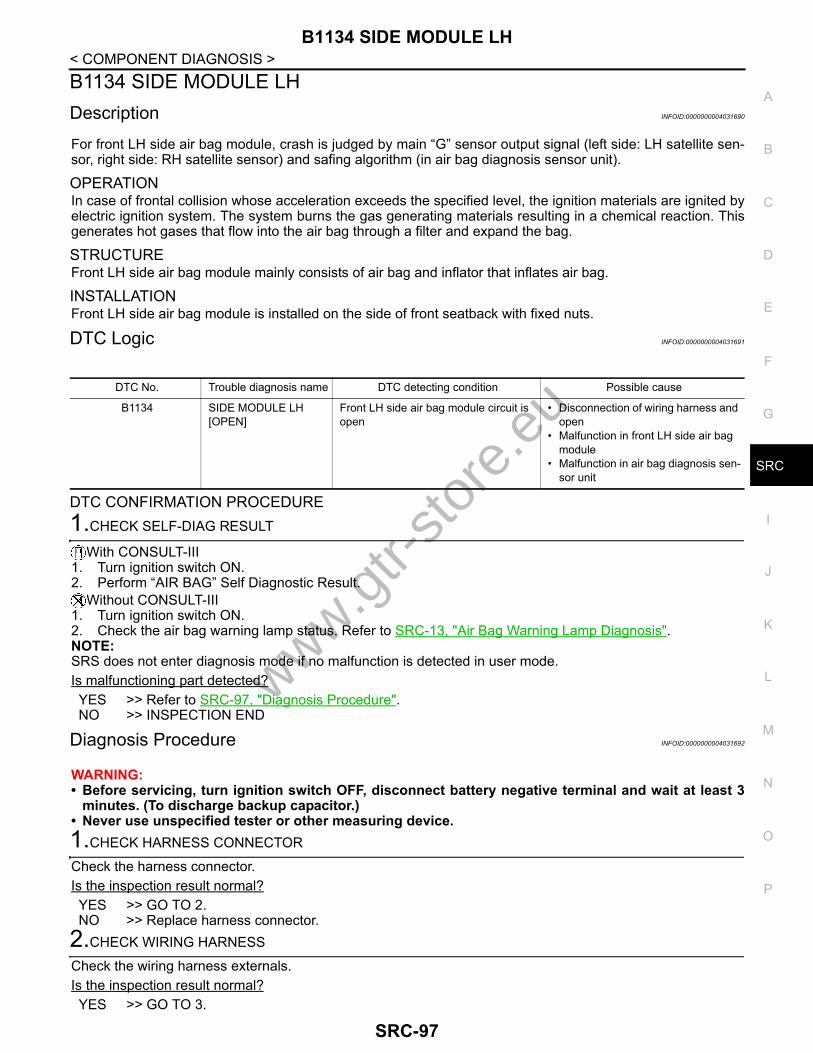
B1134 SIDE MODULE LH
C
D
E
F
G
I
J
K
L
M
A
B
RC
N
O
P
< COMPONENT DIAGNOSIS >
S
B1134 SIDE MODULE LHDescription INFOID:0000000004031690
For front LH side air bag module, crash is judged by main “G” sensor output signal (left side: LH satellite sen-sor, right side: RH satellite sensor) and safing algorithm (in air bag diagnosis sensor unit).
OPERATIONIn case of frontal collision whose acceleration exceeds the specified level, the ignition materials are ignited byelectric ignition system. The system burns the gas generating materials resulting in a chemical reaction. Thisgenerates hot gases that flow into the air bag through a filter and expand the bag.
STRUCTUREFront LH side air bag module mainly consists of air bag and inflator that inflates air bag.
INSTALLATIONFront LH side air bag module is installed on the side of front seatback with fixed nuts.
DTC Logic INFOID:0000000004031691
DTC CONFIRMATION PROCEDURE1.CHECK SELF-DIAG RESULT
With CONSULT-III1. Turn ignition switch ON.2. Perform “AIR BAG” Self Diagnostic Result.
Without CONSULT-III1. Turn ignition switch ON.2. Check the air bag warning lamp status. Refer to SRC-13, "Air Bag Warning Lamp Diagnosis".NOTE:SRS does not enter diagnosis mode if no malfunction is detected in user mode.Is malfunctioning part detected?YES >> Refer to SRC-97, "Diagnosis Procedure".NO >> INSPECTION END
Diagnosis Procedure INFOID:0000000004031692
WARNING:• Before servicing, turn ignition switch OFF, disconnect battery negative terminal and wait at least 3
minutes. (To discharge backup capacitor.)• Never use unspecified tester or other measuring device. 1.CHECK HARNESS CONNECTOR
Check the harness connector.Is the inspection result normal?YES >> GO TO 2.NO >> Replace harness connector.
2.CHECK WIRING HARNESS
Check the wiring harness externals.Is the inspection result normal?YES >> GO TO 3.
DTC No. Trouble diagnosis name DTC detecting condition Possible cause
B1134 SIDE MODULE LH [OPEN]
Front LH side air bag module circuit is open
• Disconnection of wiring harness and open
• Malfunction in front LH side air bag module
• Malfunction in air bag diagnosis sen-sor unit
www.gtr-
store
.eu
SRC-97

B1134 SIDE MODULE LH
< COMPONENT DIAGNOSIS >NO >> Replace wiring harness.3.REPLACE FRONT SIDE AIR BAG MODULE
1. Replace front LH side air bag module. Refer to SE-29, "Exploded View".2. Perform DTC confirmation procedure. Refer to SRC-97, "DTC Logic".Is DTC detected?YES >> GO TO 4. NO >> INSPECTION END
4.REPLACE AIR BAG DIAGNOSIS SENSOR UNIT
1. Replace air bag diagnosis sensor unit. Refer to SR-19, "Exploded View".2. Perform DTC confirmation procedure. Refer to SRC-97, "DTC Logic".Is DTC detected?YES >> GO TO 1. NO >> INSPECTION END
www.gtr-
store
.eu
SRC-98

B1135 SIDE MODULE LH
C
D
E
F
G
I
J
K
L
M
A
B
RC
N
O
P
< COMPONENT DIAGNOSIS >
S
B1135 SIDE MODULE LHDescription INFOID:0000000004031693
For front LH side air bag module, crash is judged by main “G” sensor output signal (left side: LH satellite sen-sor, right side: RH satellite sensor) and safing algorithm (in air bag diagnosis sensor unit).
OPERATIONIn case of frontal collision whose acceleration exceeds the specified level, the ignition materials are ignited byelectric ignition system. The system burns the gas generating materials resulting in a chemical reaction. Thisgenerates hot gases that flow into the air bag through a filter and expand the bag.
STRUCTUREFront LH side air bag module mainly consists of air bag and inflator that inflates air bag.
INSTALLATIONFront LH side air bag module is installed on the side of front seatback with fixed nuts.
DTC Logic INFOID:0000000004031694
DTC CONFIRMATION PROCEDURE1.CHECK SELF-DIAG RESULT
With CONSULT-III1. Turn ignition switch ON.2. Perform “AIR BAG” Self Diagnostic Result.
Without CONSULT-III1. Turn ignition switch ON.2. Check the air bag warning lamp status. Refer to SRC-13, "Air Bag Warning Lamp Diagnosis".NOTE:SRS does not enter diagnosis mode if no malfunction is detected in user mode.Is malfunctioning part detected?YES >> Refer to SRC-99, "Diagnosis Procedure".NO >> INSPECTION END
Diagnosis Procedure INFOID:0000000004031695
WARNING:• Before servicing, turn ignition switch OFF, disconnect battery negative terminal and wait at least 3
minutes. (To discharge backup capacitor.)• Never use unspecified tester or other measuring device.1.CHECK HARNESS CONNECTOR
Check the harness connector.Is the inspection result normal?YES >> GO TO 2.NO >> Replace harness connector.
2.CHECK WIRING HARNESS
Check the wiring harness externals.Is the inspection result normal?YES >> GO TO 3.
DTC No. Trouble diagnosis name DTC detecting condition Possible cause
B1135 SIDE MODULE LH [VB-SHORT]
Front LH side air bag module circuit is shorted to some power supply circuit
• Disconnection of wiring harness and short
• Malfunction in front LH side air bag module
• Malfunction in air bag diagnosis sen-sor unit
www.gtr-
store
.eu
SRC-99

B1135 SIDE MODULE LH
< COMPONENT DIAGNOSIS >NO >> Replace wiring harness.3.REPLACE FRONT SIDE AIR BAG MODULE
1. Replace front LH side air bag module. Refer to SE-29, "Exploded View".2. Perform DTC confirmation procedure. Refer to SRC-99, "DTC Logic".Is DTC detected?YES >> GO TO 4. NO >> INSPECTION END
4.REPLACE AIR BAG DIAGNOSIS SENSOR UNIT
1. Replace air bag diagnosis sensor unit. Refer to SR-19, "Exploded View".2. Perform DTC confirmation procedure. Refer to SRC-99, "DTC Logic".Is DTC detected?YES >> GO TO 1. NO >> INSPECTION END
www.gtr-
store
.eu
SRC-100

B1136 SIDE MODULE LH
C
D
E
F
G
I
J
K
L
M
A
B
RC
N
O
P
< COMPONENT DIAGNOSIS >
S
B1136 SIDE MODULE LHDescription INFOID:0000000004031696
For front LH side air bag module, crash is judged by main “G” sensor output signal (left side: LH satellite sen-sor, right side: RH satellite sensor) and safing algorithm (in air bag diagnosis sensor unit).
OPERATIONIn case of frontal collision whose acceleration exceeds the specified level, the ignition materials are ignited byelectric ignition system. The system burns the gas generating materials resulting in a chemical reaction. Thisgenerates hot gases that flow into the air bag through a filter and expand the bag.
STRUCTUREFront LH side air bag module mainly consists of air bag and inflator that inflates air bag.
INSTALLATIONFront LH side air bag module is installed on the side of front seatback with fixed nuts.
DTC Logic INFOID:0000000004031697
DTC CONFIRMATION PROCEDURE1.CHECK SELF-DIAG RESULT
With CONSULT-III1. Turn ignition switch ON.2. Perform “AIR BAG” Self Diagnostic Result.
Without CONSULT-III1. Turn ignition switch ON.2. Check the air bag warning lamp status. Refer to SRC-13, "Air Bag Warning Lamp Diagnosis".NOTE:SRS does not enter diagnosis mode if no malfunction is detected in user mode.Is malfunctioning part detected?YES >> Refer to SRC-101, "Diagnosis Procedure".NO >> INSPECTION END
Diagnosis Procedure INFOID:0000000004031698
WARNING:• Before servicing, turn ignition switch OFF, disconnect battery negative terminal and wait at least 3
minutes. (To discharge backup capacitor.)• Never use unspecified tester or other measuring device.1.CHECK HARNESS CONNECTOR
Check the harness connector.Is the inspection result normal?YES >> GO TO 2.NO >> Replace harness connector.
2.CHECK WIRING HARNESS
Check the wiring harness externals.Is the inspection result normal?YES >> GO TO 3.
DTC No. Trouble diagnosis name DTC detecting condition Possible cause
B1136 SIDE MODULE LH [GND-SHORT]
Front LH side air bag module circuit is shorted to ground
• Disconnection of wiring harness and short
• Malfunction in front LH side air bag module
• Malfunction in air bag diagnosis sen-sor unit
www.gtr-
store
.eu
SRC-101

B1136 SIDE MODULE LH
< COMPONENT DIAGNOSIS >NO >> Replace wiring harness.3.REPLACE FRONT SIDE AIR BAG MODULE
1. Replace front LH side air bag module. Refer to SE-29, "Exploded View".2. Perform DTC confirmation procedure. Refer to SRC-101, "DTC Logic".Is DTC detected?YES >> GO TO 4. NO >> INSPECTION END
4.REPLACE AIR BAG DIAGNOSIS SENSOR UNIT
1. Replace air bag diagnosis sensor unit. Refer to SR-19, "Exploded View".2. Perform DTC confirmation procedure. Refer to SRC-101, "DTC Logic".Is DTC detected?YES >> GO TO 1. NO >> INSPECTION END
www.gtr-
store
.eu
SRC-102

B1137 SIDE MODULE LH
C
D
E
F
G
I
J
K
L
M
A
B
RC
N
O
P
< COMPONENT DIAGNOSIS >
S
B1137 SIDE MODULE LHDescription INFOID:0000000004031699
For front LH side air bag module, crash is judged by main “G” sensor output signal (left side: LH satellite sen-sor, right side: RH satellite sensor) and safing algorithm (in air bag diagnosis sensor unit).
OPERATIONIn case of frontal collision whose acceleration exceeds the specified level, the ignition materials are ignited byelectric ignition system. The system burns the gas generating materials resulting in a chemical reaction. Thisgenerates hot gases that flow into the air bag through a filter and expand the bag.
STRUCTUREFront LH side air bag module mainly consists of air bag and inflator that inflates air bag.
INSTALLATIONFront LH side air bag module is installed on the side of front seatback with fixed nuts.
DTC Logic INFOID:0000000004031700
DTC CONFIRMATION PROCEDURE1.CHECK SELF-DIAG RESULT
With CONSULT-III1. Turn ignition switch ON.2. Perform “AIR BAG” Self Diagnostic Result.
Without CONSULT-III1. Turn ignition switch ON.2. Check the air bag warning lamp status. Refer to SRC-13, "Air Bag Warning Lamp Diagnosis".NOTE:SRS does not enter diagnosis mode if no malfunction is detected in user mode.Is malfunctioning part detected?YES >> Refer to SRC-103, "Diagnosis Procedure".NO >> INSPECTION END
Diagnosis Procedure INFOID:0000000004031701
WARNING:• Before servicing, turn ignition switch OFF, disconnect battery negative terminal and wait at least 3
minutes. (To discharge backup capacitor.)• Never use un specified tester or other measuring device. 1.CHECK HARNESS CONNECTOR
Check the harness connector.Is the inspection result normal?YES >> GO TO 2.NO >> Replace harness connector.
2.CHECK WIRING HARNESS
Check the wiring harness externals.Is the inspection result normal?YES >> GO TO 3.
DTC No. Trouble diagnosis name DTC detecting condition Possible cause
B1137 SIDE MODULE LH [SHORT]
Front LH side air bag module circuit are shorted to each other
• Disconnection of wiring harness and short
• Malfunction in front LH side air bag module
• Malfunction in air bag diagnosis sen-sor unit
www.gtr-
store
.eu
SRC-103

B1137 SIDE MODULE LH
< COMPONENT DIAGNOSIS >NO >> Replace wiring harness.3.REPLACE FRONT SIDE AIR BAG MODULE
1. Replace front LH side air bag module. Refer to SE-29, "Exploded View".2. Perform DTC confirmation procedure. Refer to SRC-103, "DTC Logic".Is DTC detected?YES >> GO TO 4. NO >> INSPECTION END
4.REPLACE AIR BAG DIAGNOSIS SENSOR UNIT
1. Replace air bag diagnosis sensor unit. Refer to SR-19, "Exploded View".2. Perform DTC confirmation procedure. Refer to SRC-103, "DTC Logic".Is DTC detected?YES >> GO TO 1. NO >> INSPECTION END
www.gtr-
store
.eu
SRC-104

B1138, B1139, B1140, B1141, B1142, B1143 DIAGNOSIS SENSOR UNIT
C
D
E
F
G
I
J
K
L
M
A
B
RC
N
O
P
< COMPONENT DIAGNOSIS >
S
B1138, B1139, B1140, B1141, B1142, B1143 DIAGNOSIS SENSOR UNITDescription INFOID:0000000004031702
Checks the entire SRS and displays the malfunction either by illuminating or blinking the air bag warning lampon the combination meter. Malfunctioning part can be detected by on board self-diagnosis system and CON-SULT-III.
OPERATIONIt detects a shock that exceeds a specified level and monitors whether the driver and passenger air bags, frontside air bag, side curtain air bag and pre-tensioner seat belts operate normally.
STRUCTUREIt contains the “G” sensors for both frontal and side collisions and spare battery function in case of main bat-tery damage in collision.
INSTALLATIONAir bag diagnosis sensor unit is installed under the center console with fixed bolts.
DTC Logic INFOID:0000000004031703
DTC CONFIRMATION PROCEDURE1.CHECK SELF-DIAG RESULT
With CONSULT-III1. Turn ignition switch ON.2. Perform “AIR BAG” Self Diagnostic Result.
Without CONSULT-III1. Turn ignition switch ON.2. Check the air bag warning lamp status. Refer to SRC-13, "Air Bag Warning Lamp Diagnosis".NOTE:SRS does not enter diagnosis mode if no malfunction is detected in user mode.Is malfunctioning part detected?YES >> Refer to SRC-105, "Diagnosis Procedure".NO >> INSPECTION END
Diagnosis Procedure INFOID:0000000004031704
WARNING:• Before servicing, turn ignition switch OFF, disconnect battery negative terminal and wait at least 3
minutes. (To discharge backup capacitor.)• Never use unspecified tester or other measuring device. 1.CHECK HARNESS CONNECTOR
Check the harness connector.Is the inspection result normal?YES >> GO TO 2.NO >> Replace harness connectors.
2.CHECK WIRING HARNESS
Check the wiring harness externals.Is the inspection result normal?
DTC No. Trouble diagnosis name DTC detecting condition Possible cause
B1138B1139B1140B1141B1142B1143
CONTROL UNIT Air bag diagnosis sensor unit is mal-functioning or out of the specification
• Malfunction in air bag diagnosis sen-sor unit
• Configuration in air bag diagnosis sensor unit does not match the vehi-cles specification
www.gtr-
store
.eu
SRC-105

B1138, B1139, B1140, B1141, B1142, B1143 DIAGNOSIS SENSOR UNIT
< COMPONENT DIAGNOSIS >YES >> GO TO 3.NO >> Replace wiring harness.3.REPLACE AIR BAG DIAGNOSIS SENSOR UNIT
1. Replace air bag diagnosis sensor unit. Refer to SR-19, "Exploded View".2. Perform DTC confirmation procedure. Refer to SRC-105, "DTC Logic".Is DTC detected?YES >> GO TO 1. NO >> INSPECTION END
www.gtr-
store
.eu
SRC-106

B1145 CURTAIN MODULE RH
C
D
E
F
G
I
J
K
L
M
A
B
RC
N
O
P
< COMPONENT DIAGNOSIS >
S
B1145 CURTAIN MODULE RHDescription INFOID:0000000004031708
For RH side curtain air bag module, crash is judged by main “G” sensor output signal (left side: LH satellitesensor, right side: RH satellite sensor) and safing algorithm (in air bag diagnosis sensor unit).
OPERATIONIn case of frontal collision whose acceleration exceeds the specified level, the ignition materials are ignited byelectric ignition system. The system burns the gas generating materials resulting in a chemical reaction. Thisgenerates hot gases that flow into the air bag through a filter and expand the bag.
STRUCTURERH side curtain air bag module mainly consists of air bag and inflator that inflates air bag.
INSTALLATIONRH side curtain air bag module is installed on the roof side with fixed bolts.
DTC Logic INFOID:0000000004031709
DTC CONFIRMATION PROCEDURE1.CHECK SELF-DIAG RESULT
With CONSULT-III1. Turn ignition switch ON.2. Perform “AIR BAG” Self Diagnostic Result.
Without CONSULT-III1. Turn ignition switch ON.2. Check the air bag warning lamp status. Refer to SRC-13, "Air Bag Warning Lamp Diagnosis".NOTE:SRS does not enter diagnosis mode if no malfunction is detected in user mode.Is malfunctioning part detected?YES >> Refer to SRC-107, "Diagnosis Procedure".NO >> INSPECTION END
Diagnosis Procedure INFOID:0000000004031710
WARNING:• Before servicing, turn ignition switch OFF, disconnect battery negative terminal and wait at least 3
minutes. (To discharge backup capacitor.)• Never use unspecified tester or other measuring device. 1.CHECK HARNESS CONNECTOR
Check the harness connector.Is the inspection result normal?YES >> GO TO 2.NO >> Replace harness connector.
2.CHECK WIRING HARNESS
Check the wiring harness externals.Is the inspection result normal?YES >> GO TO 3.
DTC No. Trouble diagnosis name DTC detecting condition Possible cause
B1145 CURTAIN MODULE RH [OPEN]
RH side curtain air bag module circuit is open
• Disconnection of wiring harness and open
• Malfunction in RH side curtain air bag module
• Malfunction in air bag diagnosis sen-sor unit
www.gtr-
store
.eu
SRC-107

B1145 CURTAIN MODULE RH
< COMPONENT DIAGNOSIS >NO >> Replace wiring harness.3.REPLACE SIDE CURTAIN AIR BAG MODULE
1. Replace RH side curtain air bag module. Refer to SR-13, "Exploded View"2. Perform DTC confirmation procedure. Refer to SRC-107, "DTC Logic".Is DTC detected?YES >> GO TO 4. NO >> INSPECTION END
4.REPLACE AIR BAG DIAGNOSIS SENSOR UNIT
1. Replace air bag diagnosis sensor unit. Refer to SR-19, "Exploded View".2. Perform DTC confirmation procedure. Refer to SRC-107, "DTC Logic".Is DTC detected?YES >> GO TO 1. NO >> INSPECTION END
www.gtr-
store
.eu
SRC-108

B1146 CURTAIN MODULE RH
C
D
E
F
G
I
J
K
L
M
A
B
RC
N
O
P
< COMPONENT DIAGNOSIS >
S
B1146 CURTAIN MODULE RHDescription INFOID:0000000004031711
For RH side curtain air bag module, crash is judged by main “G” sensor output signal (left side: LH satellitesensor, right side: RH satellite sensor) and safing algorithm (in air bag diagnosis sensor unit).
OPERATIONIn case of frontal collision whose acceleration exceeds the specified level, the ignition materials are ignited byelectric ignition system. The system burns the gas generating materials resulting in a chemical reaction. Thisgenerates hot gases that flow into the air bag through a filter and expand the bag.
STRUCTURERH side curtain air bag module mainly consists of air bag and inflator that inflates air bag.
INSTALLATIONRH side curtain air bag module is installed on the roof side with fixed bolts.
DTC Logic INFOID:0000000004031712
DTC CONFIRMATION PROCEDURE1.CHECK SELF-DIAG RESULT
With CONSULT-III1. Turn ignition switch ON.2. Perform “AIR BAG” Self Diagnostic Result.
Without CONSULT-III1. Turn ignition switch ON.2. Check the air bag warning lamp status. Refer to SRC-13, "Air Bag Warning Lamp Diagnosis".NOTE:SRS does not enter diagnosis mode if no malfunction is detected in user mode.Is malfunctioning part detected?YES >> Refer to SRC-109, "Diagnosis Procedure".NO >> INSPECTION END
Diagnosis Procedure INFOID:0000000004031713
WARNING:• Before servicing, turn ignition switch OFF, disconnect battery negative terminal and wait at least 3
minutes. (To discharge backup capacitor.)• Never use unspecified tester or other measuring device.1.CHECK HARNESS CONNECTOR
Check the harness connector.Is the inspection result normal?YES >> GO TO 2.NO >> Replace harness connector.
2.CHECK WIRING HARNESS
Check the wiring harness externals.Is the inspection result normal?YES >> GO TO 3.
DTC No. Trouble diagnosis name DTC detecting condition Possible cause
B1146 CURTAIN MODULE RH [VB-SHORT]
RH side curtain air bag module circuit is shorted to some power supply circuit
• Disconnection of wiring harness and short
• Malfunction in RH side curtain air bag module
• Malfunction in air bag diagnosis sen-sor unit
www.gtr-
store
.eu
SRC-109

B1146 CURTAIN MODULE RH
< COMPONENT DIAGNOSIS >NO >> Replace wiring harness.3.REPLACE SIDE CURTAIN AIR BAG MODULE
1. Replace RH side curtain air bag module. Refer to SR-13, "Exploded View"2. Perform DTC confirmation procedure. Refer to SRC-109, "DTC Logic".Is DTC detected?YES >> GO TO 4. NO >> INSPECTION END
4.REPLACE AIR BAG DIAGNOSIS SENSOR UNIT
1. Replace air bag diagnosis sensor unit. Refer to SR-19, "Exploded View".2. Perform DTC confirmation procedure. Refer to SRC-109, "DTC Logic".Is DTC detected?YES >> GO TO 1. NO >> INSPECTION END
www.gtr-
store
.eu
SRC-110

B1147 CURTAIN MODULE RH
C
D
E
F
G
I
J
K
L
M
A
B
RC
N
O
P
< COMPONENT DIAGNOSIS >
S
B1147 CURTAIN MODULE RHDescription INFOID:0000000004031714
For RH side curtain air bag module, crash is judged by main “G” sensor output signal (left side: LH satellitesensor, right side: RH satellite sensor) and safing algorithm (in air bag diagnosis sensor unit).
OPERATIONIn case of frontal collision whose acceleration exceeds the specified level, the ignition materials are ignited byelectric ignition system. The system burns the gas generating materials resulting in a chemical reaction. Thisgenerates hot gases that flow into the air bag through a filter and expand the bag.
STRUCTURERH side curtain air bag module mainly consists of air bag and inflator that inflates air bag.
INSTALLATIONRH side curtain air bag module is installed on the roof side with fixed bolts.
DTC Logic INFOID:0000000004031715
DTC CONFIRMATION PROCEDURE1.CHECK SELF-DIAG RESULT
With CONSULT-III1. Turn ignition switch ON.2. Perform “AIR BAG” Self Diagnostic Result.
Without CONSULT-III1. Turn ignition switch ON.2. Check the air bag warning lamp status. Refer to SRC-13, "Air Bag Warning Lamp Diagnosis".NOTE:SRS does not enter diagnosis mode if no malfunction is detected in user mode.Is malfunctioning part detected?YES >> Refer to SRC-111, "Diagnosis Procedure".NO >> INSPECTION END
Diagnosis Procedure INFOID:0000000004031716
WARNING:• Before servicing, turn ignition switch OFF, disconnect battery negative terminal and wait at least 3
minutes. (To discharge backup capacitor.)• Never use unspecified tester or other measuring device.1.CHECK HARNESS CONNECTOR
Check the harness connector.Is the inspection result normal?YES >> GO TO 2.NO >> Replace harness connector.
2.CHECK WIRING HARNESS
Check the wiring harness externals.Is the inspection result normal?YES >> GO TO 3.
DTC No. Trouble diagnosis name DTC detecting condition Possible cause
B1147 CURTAIN MODULE RH [GND-SHORT]
RH side curtain air bag module circuit is shorted to ground
• Disconnection of wiring harness and short
• Malfunction in RH side curtain air bag module
• Malfunction in air bag diagnosis sen-sor unit
www.gtr-
store
.eu
SRC-111

B1147 CURTAIN MODULE RH
< COMPONENT DIAGNOSIS >NO >> Replace wiring harness.3.REPLACE SIDE CURTAIN AIR BAG MODULE
1. Replace RH side curtain air bag module. Refer to SR-13, "Exploded View"2. Perform DTC confirmation procedure. Refer to SRC-111, "DTC Logic".Is DTC detected?YES >> GO TO 4. NO >> INSPECTION END
4.REPLACE AIR BAG DIAGNOSIS SENSOR UNIT
1. Replace air bag diagnosis sensor unit. Refer to SR-19, "Exploded View".2. Perform DTC confirmation procedure. Refer to SRC-111, "DTC Logic".Is DTC detected?YES >> GO TO 1. NO >> INSPECTION END
www.gtr-
store
.eu
SRC-112
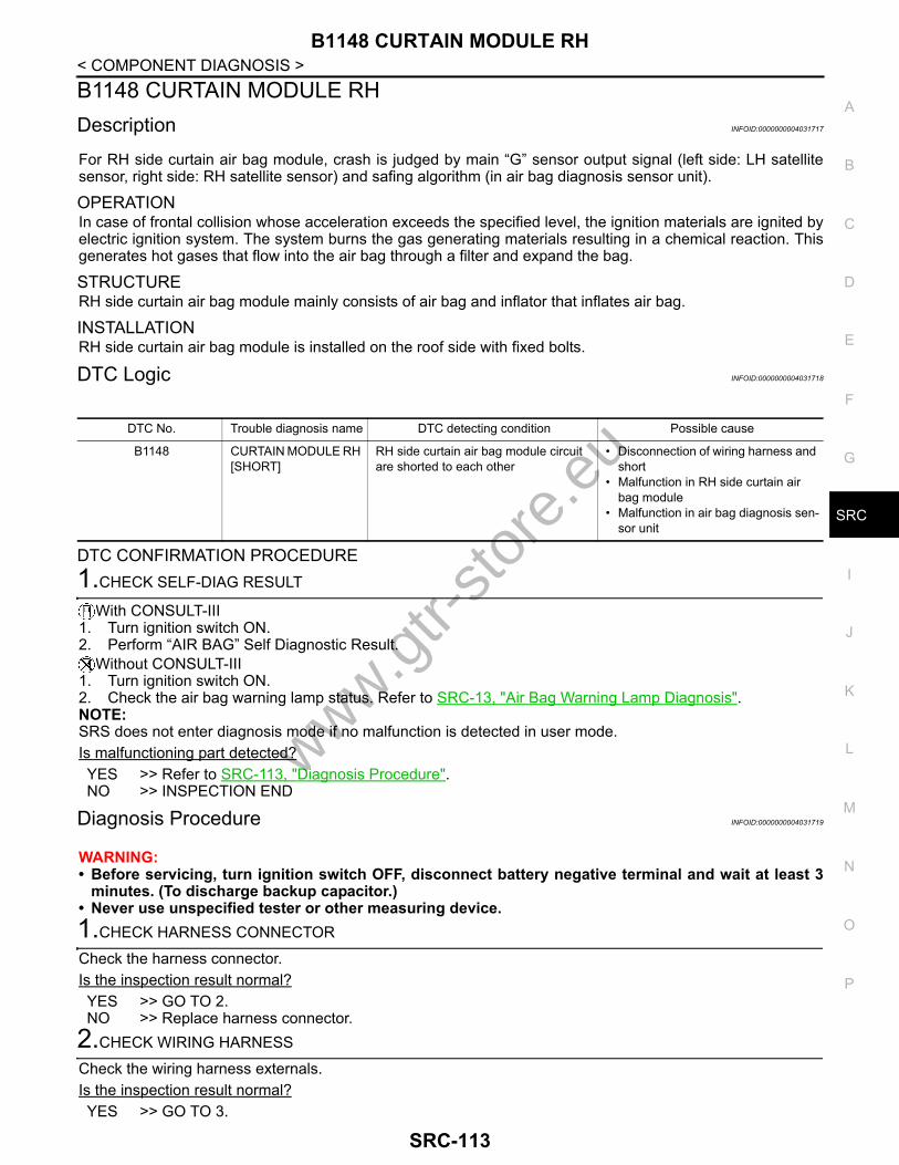
B1148 CURTAIN MODULE RH
C
D
E
F
G
I
J
K
L
M
A
B
RC
N
O
P
< COMPONENT DIAGNOSIS >
S
B1148 CURTAIN MODULE RHDescription INFOID:0000000004031717
For RH side curtain air bag module, crash is judged by main “G” sensor output signal (left side: LH satellitesensor, right side: RH satellite sensor) and safing algorithm (in air bag diagnosis sensor unit).
OPERATIONIn case of frontal collision whose acceleration exceeds the specified level, the ignition materials are ignited byelectric ignition system. The system burns the gas generating materials resulting in a chemical reaction. Thisgenerates hot gases that flow into the air bag through a filter and expand the bag.
STRUCTURERH side curtain air bag module mainly consists of air bag and inflator that inflates air bag.
INSTALLATIONRH side curtain air bag module is installed on the roof side with fixed bolts.
DTC Logic INFOID:0000000004031718
DTC CONFIRMATION PROCEDURE1.CHECK SELF-DIAG RESULT
With CONSULT-III1. Turn ignition switch ON.2. Perform “AIR BAG” Self Diagnostic Result.
Without CONSULT-III1. Turn ignition switch ON.2. Check the air bag warning lamp status. Refer to SRC-13, "Air Bag Warning Lamp Diagnosis".NOTE:SRS does not enter diagnosis mode if no malfunction is detected in user mode.Is malfunctioning part detected?YES >> Refer to SRC-113, "Diagnosis Procedure".NO >> INSPECTION END
Diagnosis Procedure INFOID:0000000004031719
WARNING:• Before servicing, turn ignition switch OFF, disconnect battery negative terminal and wait at least 3
minutes. (To discharge backup capacitor.)• Never use unspecified tester or other measuring device. 1.CHECK HARNESS CONNECTOR
Check the harness connector.Is the inspection result normal?YES >> GO TO 2.NO >> Replace harness connector.
2.CHECK WIRING HARNESS
Check the wiring harness externals.Is the inspection result normal?YES >> GO TO 3.
DTC No. Trouble diagnosis name DTC detecting condition Possible cause
B1148 CURTAIN MODULE RH [SHORT]
RH side curtain air bag module circuit are shorted to each other
• Disconnection of wiring harness and short
• Malfunction in RH side curtain air bag module
• Malfunction in air bag diagnosis sen-sor unit
www.gtr-
store
.eu
SRC-113

B1148 CURTAIN MODULE RH
< COMPONENT DIAGNOSIS >NO >> Replace wiring harness.3.REPLACE SIDE CURTAIN AIR BAG MODULE
1. Replace RH side curtain air bag module. Refer to SR-13, "Exploded View"2. Perform DTC confirmation procedure. Refer to SRC-113, "DTC Logic".Is DTC detected?YES >> GO TO 4. NO >> INSPECTION END
4.REPLACE AIR BAG DIAGNOSIS SENSOR UNIT
1. Replace air bag diagnosis sensor unit. Refer to SR-19, "Exploded View".2. Perform DTC confirmation procedure. Refer to SRC-113, "DTC Logic".Is DTC detected?YES >> GO TO 1. NO >> INSPECTION END
www.gtr-
store
.eu
SRC-114

B1150 CURTAIN MODULE LH
C
D
E
F
G
I
J
K
L
M
A
B
RC
N
O
P
< COMPONENT DIAGNOSIS >
S
B1150 CURTAIN MODULE LHDescription INFOID:0000000004031720
For RH side curtain air bag module, crash is judged by main “G” sensor output signal (left side: LH satellitesensor, right side: RH satellite sensor) and safing algorithm (in air bag diagnosis sensor unit).
OPERATIONIn case of frontal collision whose acceleration exceeds the specified level, the ignition materials are ignited byelectric ignition system. The system burns the gas generating materials resulting in a chemical reaction. Thisgenerates hot gases that flow into the air bag through a filter and expand the bag.
STRUCTURELH side curtain air bag module mainly consists of air bag and inflator that inflates air bag.
INSTALLATIONLH side curtain air bag module is installed on the roof side with fixed bolts.
DTC Logic INFOID:0000000004031721
DTC CONFIRMATION PROCEDURE1.CHECK SELF-DIAG RESULT
With CONSULT-III1. Turn ignition switch ON.2. Perform “AIR BAG” Self Diagnostic Result.
Without CONSULT-III1. Turn ignition switch ON.2. Check the air bag warning lamp status. Refer to SRC-13, "Air Bag Warning Lamp Diagnosis".NOTE:SRS does not enter diagnosis mode if no malfunction is detected in user mode.Is malfunctioning part detected?YES >> Refer to SRC-115, "Diagnosis Procedure".NO >> INSPECTION END
Diagnosis Procedure INFOID:0000000004031722
WARNING:• Before servicing, turn ignition switch OFF, disconnect battery negative terminal and wait at least 3
minutes. (To discharge backup capacitor.)• Never use unspecified tester or other measuring device. 1.CHECK HARNESS CONNECTOR
Check the harness connector.Is the inspection result normal?YES >> GO TO 2.NO >> Replace harness connector.
2.CHECK WIRING HARNESS
Check the wiring harness externals.Is the inspection result normal?YES >> GO TO 3.
DTC No. Trouble diagnosis name DTC detecting condition Possible cause
B1150 CURTAIN MODULE LH [OPEN]
LH side curtain air bag module circuit is open
• Disconnection of wiring harness and open
• Malfunction in LH side curtain air bag module
• Malfunction in air bag diagnosis sen-sor unit
www.gtr-
store
.eu
SRC-115
B1150 CURTAIN MODULE LH
< COMPONENT DIAGNOSIS >NO >> Replace wiring harness.3.REPLACE SIDE CURTAIN AIR BAG MODULE
1. Replace LH side curtain air bag module. Refer to SR-13, "Exploded View"2. Perform DTC confirmation procedure. Refer to SRC-115, "DTC Logic".Is DTC detected?YES >> GO TO 4. NO >> INSPECTION END
4.REPLACE AIR BAG DIAGNOSIS SENSOR UNIT
1. Replace air bag diagnosis sensor unit. Refer to SR-19, "Exploded View".2. Perform DTC confirmation procedure. Refer to SRC-115, "DTC Logic".Is DTC detected?YES >> GO TO 1. NO >> INSPECTION END
www.gtr-
store
.eu
SRC-116

B1151 CURTAIN MODULE LH
C
D
E
F
G
I
J
K
L
M
A
B
RC
N
O
P
< COMPONENT DIAGNOSIS >
S
B1151 CURTAIN MODULE LHDescription INFOID:0000000004031723
For RH side curtain air bag module, crash is judged by main “G” sensor output signal (left side: LH satellitesensor, right side: RH satellite sensor) and safing algorithm (in air bag diagnosis sensor unit).
OPERATIONIn case of frontal collision whose acceleration exceeds the specified level, the ignition materials are ignited byelectric ignition system. The system burns the gas generating materials resulting in a chemical reaction. Thisgenerates hot gases that flow into the air bag through a filter and expand the bag.
STRUCTURELH side curtain air bag module mainly consists of air bag and inflator that inflates air bag.
INSTALLATIONLH side curtain air bag module is installed on the roof side with fixed bolts.
DTC Logic INFOID:0000000004031724
DTC CONFIRMATION PROCEDURE1.CHECK SELF-DIAG RESULT
With CONSULT-III1. Turn ignition switch ON.2. Perform “AIR BAG” Self Diagnostic Result.
Without CONSULT-III1. Turn ignition switch ON.2. Check the air bag warning lamp status. Refer to SRC-13, "Air Bag Warning Lamp Diagnosis".NOTE:SRS does not enter diagnosis mode if no malfunction is detected in user mode.Is malfunctioning part detected?YES >> Refer to SRC-117, "Diagnosis Procedure".NO >> INSPECTION END
Diagnosis Procedure INFOID:0000000004031725
WARNING:• Before servicing, turn ignition switch OFF, disconnect battery negative terminal and wait at least 3
minutes. (To discharge backup capacitor.)• Never use unspecified tester or other measuring device.1.CHECK HARNESS CONNECTOR
Check the harness connector.Is the inspection result normal?YES >> GO TO 2.NO >> Replace harness connector.
2.CHECK WIRING HARNESS
Check the wiring harness externals.Is the inspection result normal?YES >> GO TO 3.
DTC No. Trouble diagnosis name DTC detecting condition Possible cause
B1151 CURTAIN MODULE LH [VB-SHORT]
LH side curtain air bag module circuit is shorted to some power supply circuit
• Disconnection of wiring harness and short
• Malfunction in LH side curtain air bag module
• Malfunction in air bag diagnosis sen-sor unit
www.gtr-
store
.eu
SRC-117

B1151 CURTAIN MODULE LH
< COMPONENT DIAGNOSIS >NO >> Replace wiring harness.3.REPLACE SIDE CURTAIN AIR BAG MODULE
1. Replace LH side curtain air bag module. Refer to SR-13, "Exploded View"2. Perform DTC confirmation procedure. Refer to SRC-117, "DTC Logic".Is DTC detected?YES >> GO TO 4.NO >> INSPECTION END
4.REPLACE AIR BAG DIAGNOSIS SENSOR UNIT
1. Replace air bag diagnosis sensor unit. Refer to SR-19, "Exploded View".2. Perform DTC confirmation procedure. Refer to SRC-117, "DTC Logic".Is DTC detected?YES >> GO TO 1. NO >> INSPECTION END
www.gtr-
store
.eu
SRC-118

B1152 CURTAIN MODULE LH
C
D
E
F
G
I
J
K
L
M
A
B
RC
N
O
P
< COMPONENT DIAGNOSIS >
S
B1152 CURTAIN MODULE LHDescription INFOID:0000000004031726
For RH side curtain air bag module, crash is judged by main “G” sensor output signal (left side: LH satellitesensor, right side: RH satellite sensor) and safing algorithm (in air bag diagnosis sensor unit).
OPERATIONIn case of frontal collision whose acceleration exceeds the specified level, the ignition materials are ignited byelectric ignition system. The system burns the gas generating materials resulting in a chemical reaction. Thisgenerates hot gases that flow into the air bag through a filter and expand the bag.
STRUCTURELH side curtain air bag module mainly consists of air bag and inflator that inflates air bag.
INSTALLATIONLH side curtain air bag module is installed on the roof side with fixed bolts.
DTC Logic INFOID:0000000004031727
DTC CONFIRMATION PROCEDURE1.CHECK SELF-DIAG RESULT
With CONSULT-III1. Turn ignition switch ON.2. Perform “AIR BAG” Self Diagnostic Result.
Without CONSULT-III1. Turn ignition switch ON.2. Check the air bag warning lamp status. Refer to SRC-13, "Air Bag Warning Lamp Diagnosis".NOTE:SRS does not enter diagnosis mode if no malfunction is detected in user mode.Is malfunctioning part detected?YES >> Refer to SRC-119, "Diagnosis Procedure".NO >> INSPECTION END
Diagnosis Procedure INFOID:0000000004031728
WARNING:• Before servicing, turn ignition switch OFF, disconnect battery negative terminal and wait at least 3
minutes. (To discharge backup capacitor.)• Never use unspecified tester or other measuring device.1.CHECK HARNESS CONNECTOR
Check the harness connector.Is the inspection result normal?YES >> GO TO 2.NO >> Replace harness connector.
2.CHECK WIRING HARNESS
Check the wiring harness externals.Is the inspection result normal?YES >> GO TO 3.
DTC No. Trouble diagnosis name DTC detecting condition Possible cause
B1152 CURTAIN MODULE LH [GND-SHORT]
LH side curtain air bag module circuit is shorted to ground
• Disconnection of wiring harness and short
• Malfunction in LH side curtain air bag module
• Malfunction in air bag diagnosis sen-sor unit
www.gtr-
store
.eu
SRC-119

B1152 CURTAIN MODULE LH
< COMPONENT DIAGNOSIS >NO >> Replace wiring harness.3.REPLACE SIDE CURTAIN AIR BAG MODULE
1. Replace LH side curtain air bag module. Refer to SR-13, "Exploded View"2. Perform DTC confirmation procedure. Refer to SRC-119, "DTC Logic".Is DTC detected?YES >> GO TO 4. NO >> INSPECTION END
4.REPLACE AIR BAG DIAGNOSIS SENSOR UNIT
1. Replace air bag diagnosis sensor unit. Refer to SR-19, "Exploded View".2. Perform DTC confirmation procedure. Refer to SRC-119, "DTC Logic".Is DTC detected?YES >> GO TO 1. NO >> INSPECTION END
www.gtr-
store
.eu
SRC-120

B1153 CURTAIN MODULE LH
C
D
E
F
G
I
J
K
L
M
A
B
RC
N
O
P
< COMPONENT DIAGNOSIS >
S
B1153 CURTAIN MODULE LHDescription INFOID:0000000004031729
For RH side curtain air bag module, crash is judged by main “G” sensor output signal (left side: LH satellitesensor, right side: RH satellite sensor) and safing algorithm (in air bag diagnosis sensor unit).
OPERATIONIn case of frontal collision whose acceleration exceeds the specified level, the ignition materials are ignited byelectric ignition system. The system burns the gas generating materials resulting in a chemical reaction. Thisgenerates hot gases that flow into the air bag through a filter and expand the bag.
STRUCTURELH side curtain air bag module mainly consists of air bag and inflator that inflates air bag.
INSTALLATIONLH side curtain air bag module is installed on the roof side with fixed bolts.
DTC Logic INFOID:0000000004031730
DTC CONFIRMATION PROCEDURE1.CHECK SELF-DIAG RESULT
With CONSULT-III1. Turn ignition switch ON.2. Perform “AIR BAG” Self Diagnostic Result.
Without CONSULT-III1. Turn ignition switch ON.2. Check the air bag warning lamp status. Refer to SRC-13, "Air Bag Warning Lamp Diagnosis".NOTE:SRS does not enter diagnosis mode if no malfunction is detected in user mode.Is malfunctioning part detected?YES >> Refer to SRC-121, "Diagnosis Procedure".NO >> INSPECTION END
Diagnosis Procedure INFOID:0000000004031731
WARNING:• Before servicing, turn ignition switch OFF, disconnect battery negative terminal and wait at least 3
minutes. (To discharge backup capacitor.)• Never use unspecified tester or other measuring device. 1.CHECK HARNESS CONNECTOR
Check the harness connector.Is the inspection result normal?YES >> GO TO 2.NO >> Replace harness connector.
2.CHECK WIRING HARNESS
Check the wiring harness externals.Is the inspection result normal?YES >> GO TO 3.
DTC No. Trouble diagnosis name DTC detecting condition Possible cause
B1153 CURTAIN MODULE LH [SHORT]
LH side curtain air bag module circuit are shorted to each other
• Disconnection of wiring harness and short
• Malfunction in LH side curtain air bag module
• Malfunction in air bag diagnosis sen-sor unit
www.gtr-
store
.eu
SRC-121

B1153 CURTAIN MODULE LH
< COMPONENT DIAGNOSIS >NO >> Replace wiring harness.3.REPLACE SIDE CURTAIN AIR BAG MODULE
1. Replace LH side curtain air bag module. Refer to SR-13, "Exploded View"2. Perform DTC confirmation procedure. Refer to SRC-121, "DTC Logic".Is DTC detected?YES >> GO TO 4. NO >> INSPECTION END
4.REPLACE AIR BAG DIAGNOSIS SENSOR UNIT
1. Replace air bag diagnosis sensor unit. Refer to SR-19, "Exploded View".2. Perform DTC confirmation procedure. Refer to SRC-121, "DTC Logic".Is DTC detected?YES >> GO TO 1. NO >> INSPECTION END
www.gtr-
store
.eu
SRC-122

B1202, B1203, B1204, B1205, B1206, B1207 DIAGNOSIS SENSOR UNIT
C
D
E
F
G
I
J
K
L
M
A
B
RC
N
O
P
< COMPONENT DIAGNOSIS >
S
B1202, B1203, B1204, B1205, B1206, B1207 DIAGNOSIS SENSOR UNITDescription INFOID:0000000004031741
Checks the entire SRS and displays the malfunction either by illuminating or blinking the air bag warning lampon the combination meter. Malfunctioning part can be detected by on board self-diagnosis system and CON-SULT-III.
OPERATIONIt detects a shock that exceeds a specified level and monitors whether the driver and passenger air bags, frontside air bag, side curtain air bag and pre-tensioner seat belts operate normally.
STRUCTUREIt contains the “G” sensors for both frontal and side collisions and spare battery function in case of main bat-tery damage in collision.
INSTALLATIONAir bag diagnosis sensor unit is installed under the center console with fixed bolts.
DTC Logic INFOID:0000000004031742
DTC CONFIRMATION PROCEDURE1.CHECK SELF-DIAG RESULT
With CONSULT-III1. Turn ignition switch ON.2. Perform “AIR BAG” Self Diagnostic Result.
Without CONSULT-III1. Turn ignition switch ON.2. Check the air bag warning lamp status. Refer to SRC-13, "Air Bag Warning Lamp Diagnosis".NOTE:SRS does not enter diagnosis mode if no malfunction is detected in user mode.Is malfunctioning part detected?YES >> Refer to SRC-123, "Diagnosis Procedure".NO >> INSPECTION END
Diagnosis Procedure INFOID:0000000004031743
WARNING:• Before servicing, turn ignition switch OFF, disconnect battery negative terminal and wait at least 3
minutes. (To discharge backup capacitor.)• Never use unspecified tester or other measuring device. 1.CHECK HARNESS CONNECTOR
Check the harness connector.Is the inspection result normal?YES >> GO TO 2.NO >> Replace harness connectors.
2.CHECK WIRING HARNESS
Check the wiring harness externals.Is the inspection result normal?
DTC No. Trouble diagnosis name DTC detecting condition Possible cause
B1202B1203B1204 B1205B1206B1207
CONTROL UNIT Air bag diagnosis sensor unit is mal-functioning or out of the specification
• Malfunction in air bag diagnosis sen-sor unit
• Configuration in air bag diagnosis sensor unit does not match the vehi-cles specification
www.gtr-
store
.eu
SRC-123

B1202, B1203, B1204, B1205, B1206, B1207 DIAGNOSIS SENSOR UNIT
< COMPONENT DIAGNOSIS >YES >> GO TO 3.NO >> Replace wiring harness.3.REPLACE AIR BAG DIAGNOSIS SENSOR UNIT
1. Replace air bag diagnosis sensor unit. Refer to SR-19, "Exploded View"y.2. Perform DTC confirmation procedure. Refer to SRC-123, "DTC Logic".Is DTC detected?YES >> GO TO 1. NO >> INSPECTION END
www.gtr-
store
.eu
SRC-124

B1209 FRONTAL COLLISION DETECTION
C
D
E
F
G
I
J
K
L
M
A
B
RC
N
O
P
< COMPONENT DIAGNOSIS >
S
B1209 FRONTAL COLLISION DETECTIONDescription INFOID:0000000004031744
DTC B1209 FRONTAL COLLISION DETECTIONWhen crash zone sensor detects component damage resulting from a front collision, the system blinks or illu-minates the air bag warning lamp to inform the driver. Malfunctioning can be detected by CONSULT-III.
OPERATIONThe air bags and seat belt pre-tensioners for driver and front passenger are activated by the air bag diagnosissensor unit signal transmitted at the time of the frontal collision.
STRUCTUREIt consists of crash zone sensor, air bag diagnosis sensor unit, air bags and seat belt pre-tensioners for driverand front passenger.
INSTALLATIONRefer to SR-5, "Exploded View" (Driver air bag module), SR-11, "Exploded View" (Front passenger air bagmodule), SR-15, "Exploded View"(Crash zone sensor), SR-19, "Exploded View" (Air bag diagnosis sensorunit), SB-6, "SEAT BELT RETRACTOR : Exploded View" (Front LH/RH seat belt pre-tensioner).
DTC Logic INFOID:0000000004031745
DTC CONFIRMATION PROCEDURE1.CHECK SELF-DIAG RESULT
With CONSULT-III1. Turn ignition switch ON.2. Perform “AIR BAG” Self Diagnostic Result.
Without CONSULT-III1. Turn ignition switch ON.2. Check the air bag warning lamp status. Refer to SRC-13, "Air Bag Warning Lamp Diagnosis".NOTE:SRS does not enter diagnosis mode if no malfunction is detected in user mode.Is malfunctioning part detected?YES >> Refer to SRC-125, "Diagnosis Procedure".NO >> INSPECTION END
Diagnosis Procedure INFOID:0000000004031746
WARNING:• Before servicing, turn ignition switch OFF, disconnect battery negative terminal and wait at least 3
minutes. (To discharge backup capacitor.)• Never use unspecified tester or other measuring device. 1.CHECK FRONT AIR BAG MODULE
Check front air bag modules. (Driver air bag module and/or front passenger air bag module.)Is the front air bag module deployed?YES >> Replace front air bag modules. Refer to SR-5, "Exploded View" or SR-11, "Exploded View".NO >> GO TO 2.
2.CHECK FRONT SEAT BELT PRE-TENSIONER
Check front seat belt pre-tensioner.Is the front seat belt pre-tensioner activated?
DTC No. Trouble diagnosis name DTC detecting condition Possible cause
B1209 FRONTAL COLLISION DETECTION
Front seat belt pre-tensioner, front air bag is deployed
—
www.gtr-
store
.eu
SRC-125

B1209 FRONTAL COLLISION DETECTION
< COMPONENT DIAGNOSIS >YES >> Replace front seat belt pre-tensioner. Refer to SB-6, "SEAT BELT RETRACTOR : ExplodedView".NO >> GO TO 3.
3.CHECK AIR BAG DIAGNOSIS SENSOR UNIT
Check air bag diagnosis sensor unit.Is the front air bag module and/or front seat belt pre-tensioner activated?YES >> Replace air bag diagnosis sensor unit. Refer to SR-19, "Exploded View".NO >> GO TO 4.
4.CHECK STEERING WHEEL
Check steering wheel.Is the steering wheel normal?YES >> GO TO 5.NO >> Replace steering wheel. Refer to ST-13, "Exploded View".
5.CHECK SPIRAL CABLE
1. Check the continuity of spiral cable.2. Operate the steering wheel to check excessive heavy operation force, abnormal noise or damage.Is the inspection result normal?YES >> GO TO 6.NO >> Replace spiral cable. Refer to SR-8, "Exploded View".
6.CHECK WIRING HARNESS/HARNESS CONNECTOR
Check wiring harness/harness connector.Is the wiring harness/harness connector normal?YES >> GO TO 7.NO >> Replace wiring harness/harness connector.
7.FINAL CHECK
Perform “AIR BAG” Self Diagnostic Result with CONSULT-III and/or Air bag warning lamp status.Is the inspection result normal?YES >> INSPECTION ENDNO >> Check the intermittent incident. Refer to GI-38, "Intermittent Incident".
www.gtr-
store
.eu
SRC-126
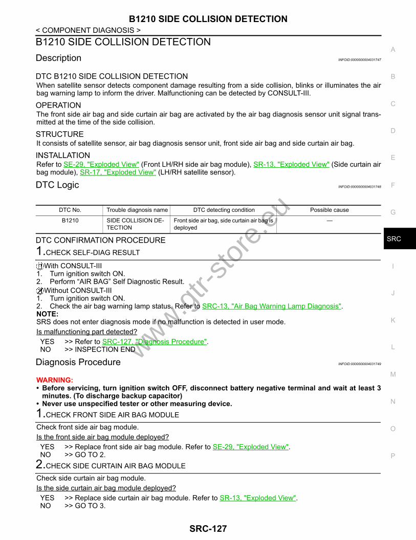
B1210 SIDE COLLISION DETECTION
C
D
E
F
G
I
J
K
L
M
A
B
RC
N
O
P
< COMPONENT DIAGNOSIS >
S
B1210 SIDE COLLISION DETECTIONDescription INFOID:0000000004031747
DTC B1210 SIDE COLLISION DETECTIONWhen satellite sensor detects component damage resulting from a side collision, blinks or illuminates the airbag warning lamp to inform the driver. Malfunctioning can be detected by CONSULT-III.
OPERATIONThe front side air bag and side curtain air bag are activated by the air bag diagnosis sensor unit signal trans-mitted at the time of the side collision.
STRUCTUREIt consists of satellite sensor, air bag diagnosis sensor unit, front side air bag and side curtain air bag.
INSTALLATIONRefer to SE-29, "Exploded View" (Front LH/RH side air bag module), SR-13, "Exploded View" (Side curtain airbag module), SR-17, "Exploded View" (LH/RH satellite sensor).
DTC Logic INFOID:0000000004031748
DTC CONFIRMATION PROCEDURE1.CHECK SELF-DIAG RESULT
With CONSULT-III1. Turn ignition switch ON.2. Perform “AIR BAG” Self Diagnostic Result.
Without CONSULT-III1. Turn ignition switch ON.2. Check the air bag warning lamp status. Refer to SRC-13, "Air Bag Warning Lamp Diagnosis".NOTE:SRS does not enter diagnosis mode if no malfunction is detected in user mode.Is malfunctioning part detected?YES >> Refer to SRC-127, "Diagnosis Procedure".NO >> INSPECTION END
Diagnosis Procedure INFOID:0000000004031749
WARNING:• Before servicing, turn ignition switch OFF, disconnect battery negative terminal and wait at least 3
minutes. (To discharge backup capacitor)• Never use unspecified tester or other measuring device. 1.CHECK FRONT SIDE AIR BAG MODULE
Check front side air bag module.Is the front side air bag module deployed?YES >> Replace front side air bag module. Refer to SE-29, "Exploded View".NO >> GO TO 2.
2.CHECK SIDE CURTAIN AIR BAG MODULE
Check side curtain air bag module.Is the side curtain air bag module deployed?YES >> Replace side curtain air bag module. Refer to SR-13, "Exploded View".NO >> GO TO 3.
DTC No. Trouble diagnosis name DTC detecting condition Possible cause
B1210 SIDE COLLISION DE-TECTION
Front side air bag, side curtain air bag is deployed
—
www.gtr-
store
.eu
SRC-127

B1210 SIDE COLLISION DETECTION
< COMPONENT DIAGNOSIS >3.CHECK SATELLITE SENSOR
Check satellite sensor.Is the front side air bag module and/or side curtain air bag module deployed?YES >> Replace satellite sensor. Refer to SR-17, "Exploded View".NO >> GO TO 4.
4.CHECK AIR BAG DIAGNOSIS SENSOR UNIT
Check air bag diagnosis sensor unit.Is the front side air bag module and/or side curtain air bag module deployed?YES >> Replace air bag diagnosis sensor unit. Refer to SR-19, "Exploded View".NO >> GO TO 5.
5.CHECK WIRING HARNESS/HARNESS CONNECTOR
Check wiring harness/harness connector.Is the wiring harness/harness connector normal?YES >> GO TO 6.NO >> Replace wiring harness/harness connector.
6.FINAL CHECK
Perform “AIR BAG” Self Diagnostic Result with CONSULT-III and/or Air bag warning lamp status.Is the inspection result normal?YES >> INSPECTION ENDNO >> Check the intermittent incident. Refer to GI-38, "Intermittent Incident".
www.gtr-
store
.eu
SRC-128

DIAGNOSIS SENSOR UNIT
C
D
E
F
G
I
J
K
L
M
A
B
RC
N
O
P
< ECU DIAGNOSIS >
S
ECU DIAGNOSISDIAGNOSIS SENSOR UNITDTC Index INFOID:0000000004031759
Diagnostic item Explanation Reference page
NO DTC IS DETECTED When malfunction is in-dicated by the “AIR BAG” warning lamp in User mode
Low battery voltage (Less than 9 V)
• Self-diagnosis result “SELF-DIAG [PAST]” (previously stored in the memory) might not be erased after re-pair
• Intermittent malfunction has been de-tected in the past
SRC-13, "Diagnosis Description"
No malfunction is detected —
CONTROL UNIT[B1001-B1015]
Air bag diagnosis sensor unit is malfunctioning or out of the speci-fied specification
• SRC-19, "DTC Logic"• SRC-21, "DTC Logic"• SRC-23, "DTC Logic"
OCCUPANT SENS C/U[UNIT FAIL][B1017][B1020][B1021]
Trouble occurs in Occupant Classification System control unit SRC-25, "DTC Logic"
OCCUPANT SENS [UNIT FAIL][B1018]
Trouble occurs in Occupant Classification System sensor SRC-27, "DTC Logic"
OCCUPANT SENS C/U[COMM FAIL][B1022]
Trouble occurs in Occupant Classification System control unit, cir-cuit of Occupant Classification System control unit air bag diagno-sis sensor unit, or air bag diagnosis sensor unit
SRC-29, "DTC Logic"
PASS A/B INDCTR CKT[B1023]
Front passenger air bag OFF indicator circuit is open or shorted to ground or the circuits are shorted each other
SRC-31, "DTC Logic"
CONTROL UNIT[B1026-B1031]
Air bag diagnosis sensor unit is malfunctioning or out of the speci-fied specification
SRC-33, "DTC Logic"
CRASH ZONE SEN[UNIT FAIL][B1033][B1034]
Crash zone sensor is malfunctioning SRC-35, "DTC Logic"
CRASH ZONE SEN[COMM FAIL][B1035][UNMATCH][B1036]
Crash zone sensor is malfunctioning or out of the specified speci-fication
SRC-37, "DTC Logic"
CONTROL UNIT[B1042-B1047]
Air bag diagnosis sensor unit is malfunctioning or out of the speci-fied specification
SRC-39, "DTC Logic"
DRIVER AIRBAG MOD-ULE[OPEN][B1049] [B1054]
Driver air bag module circuit is open (including the spiral cable) SRC-41, "DTC Logic"
DRIVER AIRBAG MOD-ULE[VB-SHORT][B1050] [B1055]
Driver air bag module circuit is shorted to some power supply cir-cuit (including the spiral cable)
SRC-43, "DTC Logic"
DRIVER AIRBAG MOD-ULE[GND-SHORT][B1051] [B1056]
Driver air bag module circuit is shorted to ground (including the spi-ral cable)
SRC-45, "DTC Logic"
www.gtr-
store
.eu
SRC-129

DIAGNOSIS SENSOR UNIT
< ECU DIAGNOSIS >DRIVER AIRBAG MOD-ULE[SHORT][B1052] [B1057]
Driver air bag module circuits are shorted to each other (including spiral cable)
SRC-47, "DTC Logic"
CONTROL UNIT[B1058-B1063]
Air bag diagnosis sensor unit is malfunctioning or out of the speci-fied specification
SRC-49, "DTC Logic"
ASSIST A/B MODULE[OPEN][B1065] [B1070]
Front passenger air bag module circuit is open SRC-51, "DTC Logic"
ASSIST A/B MODULE[VB-SHORT][B1066] [B1071]
Front passenger air bag module circuit is shorted to some power supply circuit
SRC-53, "DTC Logic"
ASSIST A/B MODULE[GND-SHORT][B1067] [B1072]
Front passenger air bag module circuit is shorted to ground SRC-55, "DTC Logic"
ASSIST A/B MODULE[SHORT][B1068] [B1073]
Front passenger air bag module circuits are shorted to each other SRC-57, "DTC Logic"
CONTROL UNIT[B1074-B1079]
Air bag diagnosis sensor unit is malfunctioning or out of the speci-fied specification
SRC-59, "DTC Logic"
PRE-TEN FRONT RH[OPEN][B1081]
Front RH seat belt pre-tensioner circuit is open SRC-61, "DTC Logic"
PRE-TEN FRONT RH[VB-SHORT][B1082]
Front RH seat belt pre-tensioner circuit is shorted to some power supply circuit
SRC-63, "DTC Logic"
PRE-TEN FRONT RH[GND-SHORT][B1083]
Front RH seat belt pre-tensioner circuit is shorted to ground SRC-65, "DTC Logic"
PRE-TEN FRONT RH[SHORT][B1084]
Front RH seat belt pre-tensioner circuits are shorted to each other SRC-67, "DTC Logic"
PRE-TEN FRONT LH[OPEN][B1086]
Front LH seat belt pre-tensioner circuit is open SRC-69, "DTC Logic"
PRE-TEN FRONT LH[VB-SHORT][B1087]
Front LH seat belt pre-tensioner circuit is shorted to some power supply circuit
SRC-71, "DTC Logic"
PRE-TEN FRONT LH[GND-SHORT][B1088]
Front LH seat belt pre-tensioner circuit is shorted to ground SRC-73, "DTC Logic"
PRE-TEN FRONT LH[SHORT][B1089]
Front LH seat belt pre-tensioner circuits are shorted to each other SRC-75, "DTC Logic"
CONTROL UNIT[B1091] [B1093]
Air bag diagnosis sensor unit is malfunctioning or out of the speci-fied specification
SRC-77, "DTC Logic"
CONTROL UNIT[B1106-B1111]
Air bag diagnosis sensor unit is malfunctioning or out of the speci-fied specification
SRC-77, "DTC Logic"
SATELLITE SENS RH[UNIT FAIL][B1113][B1114]
RH satellite sensor is out of order SRC-79, "DTC Logic"
Diagnostic item Explanation Reference page
www.gtr-
store
.eu
SRC-130

DIAGNOSIS SENSOR UNIT
C
D
E
F
G
I
J
K
L
M
A
B
RC
N
O
P
< ECU DIAGNOSIS >
S
SATELLITE SENS RH[COMM FAIL][B1115][UNMATCH][B1116]
RH satellite sensor is out of order or mis-installation SRC-81, "DTC Logic"
SATELLITE SENS LH[UNIT FAIL][B1118][B1119]
LH satellite sensor is out of order SRC-83, "DTC Logic"
SATELLITE SENS LH[COMM FAIL][B1120][UNMATCH][B1121]
LH satellite sensor is out of order or mis-installation SRC-85, "DTC Logic"
CONTROL UNIT[B1122-B1127]
Air bag diagnosis sensor unit is malfunctioning or out of the speci-fied specification
SRC-87, "DTC Logic"
SIDE MODULE RH[OPEN][B1129]
Front RH side air bag module circuit is open SRC-89, "DTC Logic"
SIDE MODULE RH[VB-SHORT][B1130]
Front RH side air bag module circuit is shorted to some power sup-ply circuit
SRC-91, "DTC Logic"
SIDE MODULE RH[GND-SHORT][B1131]
Front RH side air bag module circuit is shorted to ground SRC-93, "DTC Logic"
SIDE MODULE RH[SHORT][B1132]
Front LH seat belt pre-tensioner circuits are shorted to each other SRC-95, "DTC Logic"
SIDE MODULE LH[OPEN][B1134]
Front LH side air bag module circuit is open SRC-97, "DTC Logic"
SIDE MODULE LH[VB-SHORT][B1135]
Front LH side air bag module circuit is shorted to some power sup-ply circuit
SRC-99, "DTC Logic"
SIDE MODULE LH[GND-SHORT][B1136]
Front LH side air bag module circuit is shorted to ground SRC-101, "DTC Logic"
SIDE MODULE LH[SHORT][B1137]
Front LH side air bag module circuits are shorted to each other SRC-103, "DTC Logic"
CURTAIN MODULE RH[OPEN][B1145]
RH side curtain air bag module circuit is open SRC-107, "DTC Logic"
CURTAIN MODULE RH[VB-SHORT][B1146]
RH side curtain air bag module circuit is shorted to some power supply circuit
SRC-109, "DTC Logic"
CURTAIN MODULE RH[GND-SHORT][B1147]
RH side curtain air bag module circuit is shorted to ground SRC-111, "DTC Logic"
CURTAIN MODULE RH[SHORT][B1148]
RH side curtain air bag module circuits are shorted to each other SRC-113, "DTC Logic"
CURTAIN MODULE LH[OPEN][B1150]
LH side curtain air bag module circuit is open SRC-115, "DTC Logic"
Diagnostic item Explanation Reference page
www.gtr-
store
.eu
SRC-131

DIAGNOSIS SENSOR UNIT
< ECU DIAGNOSIS >CURTAIN MODULE LH[VB-SHORT][B1151]
LH side curtain air bag module circuit is shorted to some power supply circuits
SRC-117, "DTC Logic"
CURTAIN MODULE LH[GND-SHORT][B1152]
LH side curtain air bag module circuit is shorted to ground SRC-119, "DTC Logic"
CURTAIN MODULE LH[SHORT][B1153]
LH side curtain air bag module circuits are shorted to each other SRC-121, "DTC Logic"
CONTROL UNIT[B1155] [B1157]
Air bag diagnosis sensor unit is malfunctioning or out of the speci-fied specification
SRC-77, "DTC Logic"
CONTROL UNIT[B1202-B1207]
Air bag diagnosis sensor unit is malfunctioning or out of the speci-fied specification
SRC-123, "DTC Logic"
FRONTAL COLLISION DETECTION[B1209]
Front seat belt pre-tensioner and front air bag is deployed SRC-125, "DTC Logic"
SIDE COLLISION DE-TECTION[B1210]
Front side air bag and side curtain air bag are deployed SRC-127, "DTC Logic"
Diagnostic item Explanation Reference page
www.gtr-
store
.eu
SRC-132
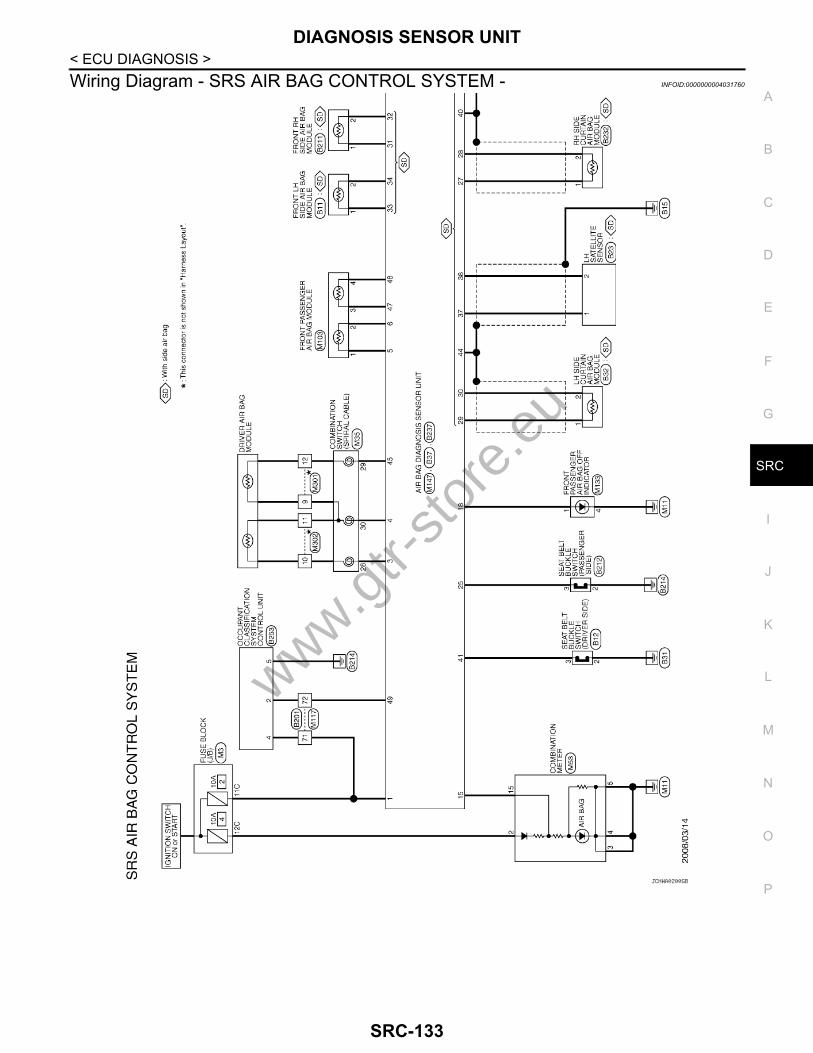
DIAGNOSIS SENSOR UNIT
C
D
E
F
G
I
J
K
L
M
A
B
RC
N
O
P
< ECU DIAGNOSIS >
S
Wiring Diagram - SRS AIR BAG CONTROL SYSTEM - INFOID:0000000004031760
JCHWA0200GB
www.gtr-
store
.eu
SRC-133
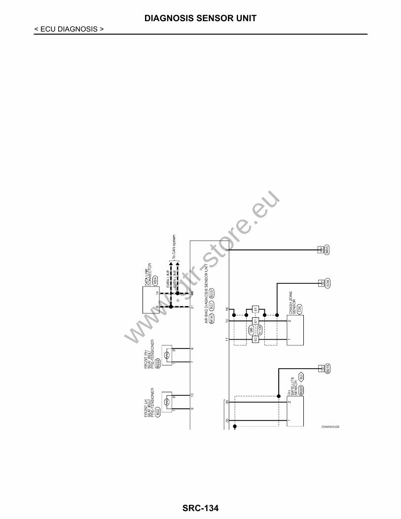
DIAGNOSIS SENSOR UNIT
< ECU DIAGNOSIS >JCHWA0201GB
www.gtr-
store
.eu
SRC-134
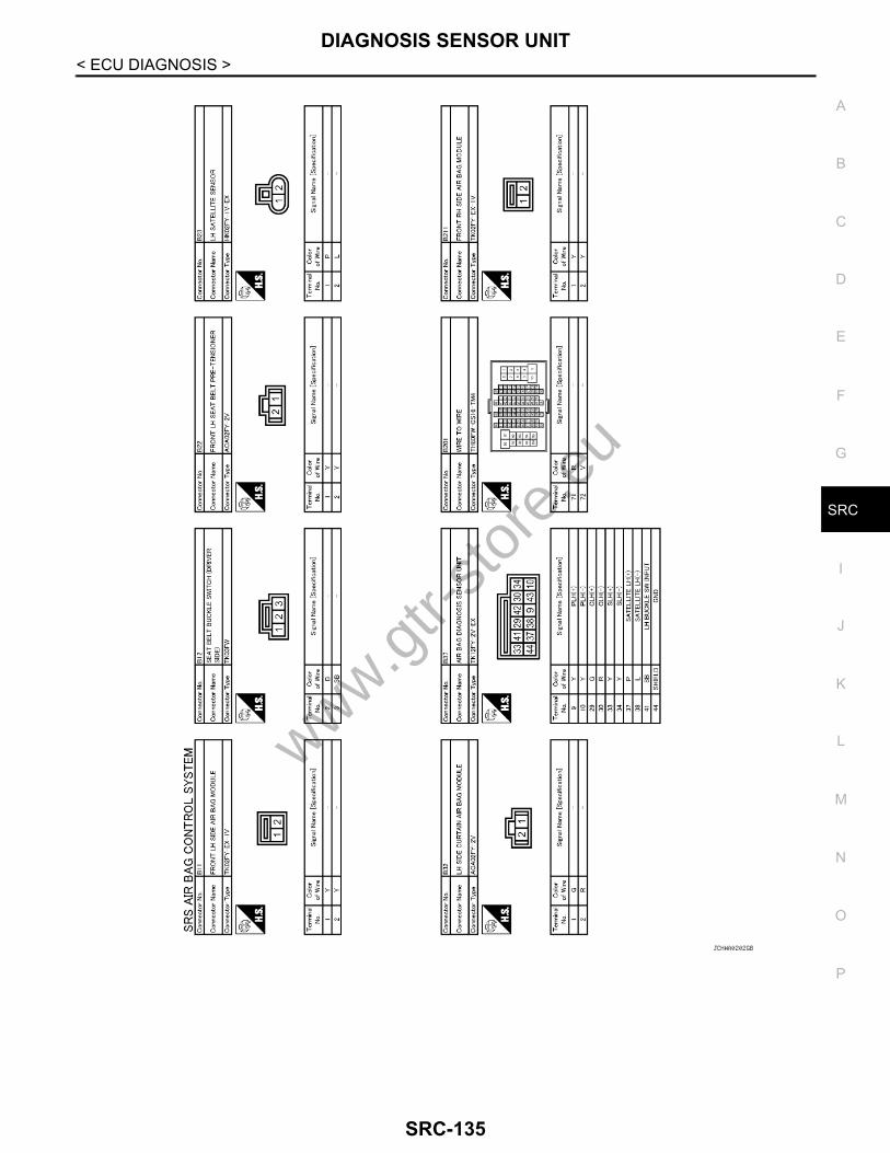
DIAGNOSIS SENSOR UNIT
C
D
E
F
G
I
J
K
L
M
A
B
RC
N
O
P
< ECU DIAGNOSIS >
S
JCHWA0202GB
www.gtr-
store
.eu
SRC-135

DIAGNOSIS SENSOR UNIT
< ECU DIAGNOSIS >JCHWA0203GB
www.gtr-
store
.eu
SRC-136

DIAGNOSIS SENSOR UNIT
C
D
E
F
G
I
J
K
L
M
A
B
RC
N
O
P
< ECU DIAGNOSIS >
S
JCHWA0204GB
www.gtr-
store
.eu
SRC-137

DIAGNOSIS SENSOR UNIT
< ECU DIAGNOSIS >JCHWA0205GB
www.gtr-
store
.eu
SRC-138

SRS AIR BAG WARNING LAMP DOES NOT TURN OFF
C
D
E
F
G
I
J
K
L
M
A
B
RC
N
O
P
< SYMPTOM DIAGNOSIS >
S
SYMPTOM DIAGNOSISSRS AIR BAG WARNING LAMP DOES NOT TURN OFFDiagnosis Procedure INFOID:0000000004031761
1.CHECK AIR BAG MODULE
Check the deployment of front air bag module.Is air bag module deployed?YES >> Refer to the following items. SR-5, "Exploded View" (Driver air bag module) SR-11, "Exploded
View" (Front passenger air bag module) SE-29, "Exploded View" (Front side air bag module) SR-13, "Exploded View" (Side curtain air bag module).
NO >> GO TO 2.2.CHECK AIR BAG FUSE
Check the air bag fuse. Refer to PG-66, "Fuse".Is 10A fuse [No.2, located in fuse block (J/B)] normal?YES >> GO TO 4.NO >> Replace the air bag fuse and GO TO 3.
3.CHECK AIR BAG FUSE AGAIN
Turn ignition switch ON.Check the air bag fuse. Refer to PG-66, "Fuse".Does the air bag fuse blow again?YES >> Repair or replace related harness.NO >> GO TO 4.
4.CHECK SELF DIAGNOSIS RESULT
Perform “AIR BAG” Self Diagnostic result.Is DTC detected?YES >> Repair or replace the malfunctioning parts.NO >> Check the intermittent incident. Refer to GI-38, "Intermittent Incident".
www.gtr-
store
.eu
SRC-139
SRS AIR BAG WARNING LAMP DOES NOT TURN ON
< SYMPTOM DIAGNOSIS >SRS AIR BAG WARNING LAMP DOES NOT TURN ONDiagnosis Procedure INFOID:00000000040317621.CHECK METER FUSE
Check the meter fuse. Refer to PG-85, "Fuse and Fusible Link Arrangement".Is 10A fuse [No.4, located in fuse block (J/B)] normal?YES >> GO TO 3.NO >> GO TO 2.
2.CHECK METER FUSE AGAIN
Replace 10A fuse [No.4, located in fuse block (J/B)] and turn ignition switch ON.Does the meter fuse blow again?YES >> Repair or replace the related harness.NO >> INSPECTION END
3.CHECK HARNESS CONNECTION
1. Check harness connection between air bag diagnosis sensor unit and combination meter.2. Disconnect air bag diagnosis sensor unit connector and turn ignition switch ON.Does air bag warning lamp turn ON?YES >> Replace air bag diagnosis sensor unit. Refer to SR-19, "Exploded View".NO >> Replace combination meter assembly. Refer to MWI-128, "Exploded View".
www.gtr-
store
.eu
SRC-140

PRECAUTIONS
C
D
E
F
G
I
J
K
L
M
A
B
RC
N
O
P
< PRECAUTION >
S
PRECAUTIONPRECAUTIONSPrecaution for Supplemental Restraint System (SRS) "AIR BAG" and "SEAT BELT PRE-TENSIONER" INFOID:0000000004025017
The Supplemental Restraint System such as “AIR BAG” and “SEAT BELT PRE-TENSIONER”, used alongwith a front seat belt, helps to reduce the risk or severity of injury to the driver and front passenger for certaintypes of collision. This system includes seat belt switch inputs and dual stage front air bag modules. The SRSsystem uses the seat belt switches to determine the front air bag deployment, and may only deploy one frontair bag, depending on the severity of a collision and whether the front occupants are belted or unbelted.Information necessary to service the system safely is included in the “SRS AIRBAG” and “SEAT BELT” of thisService Manual.WARNING:• To avoid rendering the SRS inoperative, which could increase the risk of personal injury or death in
the event of a collision which would result in air bag inflation, all maintenance must be performed byan authorized NISSAN/INFINITI dealer.
• Improper maintenance, including incorrect removal and installation of the SRS, can lead to personalinjury caused by unintentional activation of the system. For removal of Spiral Cable and Air BagModule, see the “SRS AIRBAG”.
• Never use electrical test equipment on any circuit related to the SRS unless instructed to in this Ser-vice Manual. SRS wiring harnesses can be identified by yellow and/or orange harnesses or harnessconnectors.
Service INFOID:0000000004025015
• Do not use electrical test equipment to check SRS circuits unless instructed to in this Service Manual.• Before servicing the SRS, turn ignition switch OFF, disconnect battery negative terminal and wait at least 3
minutes.For approximately 3 minutes after the battery negative terminal is removed, it is still possible for the air bagand seat belt pre-tensioner to deploy. Therefore, do not work on any SRS connectors or wires until at least 3minutes have elapsed.
• Diagnosis sensor unit must always be installed with their arrow marks “⇐” pointing towards the front of thevehicle for proper operation. Also check diagnosis sensor unit for cracks, deformities or rust before installa-tion and replace as required.
• The spiral cable must be aligned in the neutral position since its rotations are limited. Do not turn steeringwheel and column after removal of steering gear.
• Handle air bag module carefully. Always place driver and front passenger air bag modules with the pad sidefacing upward and seat mounted front side air bag module standing with the stud bolt side facing down.
• Conduct self-diagnosis to check entire SRS for proper function after replacing any components.• After air bag inflates, the front instrument panel assembly should be replaced if damaged.• Always replace instrument panel pad following front passenger air bag deployment.
Occupant Classification System Precaution INFOID:0000000004025016
• Replace Occupant Classification System control unit and passenger front seat cushion as an assembly.Refer to SE-32, "Removal and Installation".
www.gtr-
store
.eu
SRC-141