
resting ECG analysis system Operator's Manual 1200 Operators...resting ECG analysis system...
69
MAC ® 1200 resting ECG analysis system Operator's Manual Version 1.1 227 492 04 GA (USA) Revision D
Transcript of resting ECG analysis system Operator's Manual 1200 Operators...resting ECG analysis system...

MAC® 1200resting ECG analysis system
Operator's Manual
Version 1.1227 492 04 GA (USA) Revision D

2 MAC® 1200 227 492 04-D
The information contained in this manual describes version 1.1 of the MAC® 1200 resting ECG analysis system andreflects software version 5.1.
1999 GE Marquette Medical Systems, Inc. All rights reserved.
Trademarked names appear throughout this document. Rather than list the names and entities that own the trademarks orinsert a trademark symbol with each mention of the trademarked name, the publisher states that it is using the names onlyfor editorial purposes and to the benefit of the trademark owner with no intention of improperly using the trademark.
900 SC, ACCUSKETCH, AccuVision, APEX , AQUA-KNOT, ARCHIVIST, Autoseq, BABY MAC, C Qwik Connect,CardioServ, CardioSmart, CardioSys, CardioWindow, CASE, CD TELEMETRY, CENTRA, CHART GUARD, CINE35, COROLAN, CORO, COROMETRICS, Corometrics Sensor Tip, CRG PLUS, DASH, Digistore, Digital DATAQ, Efor M, EAGLE, Event-Link, FMS 101B, FMS 111, HELLIGE, IMAGE STORE, INTELLIMOTION, IQA, LASER SXP,MAC, MAC-LAB, MACTRODE, MARQUETTE, MARQUETTE MAC, MARQUETTE MEDICAL SYSTEMS,MARQUETTE UNITY NETWORK, MARS, MAX, MEDITEL, MEI, MEI in the circle logo, MEMOPORT,MEMOPORT C, MINISTORE, MINNOWS, Monarch 8000, MULTI-LINK, MULTISCRIPTOR, MUSE, MUSE CV,Neo-Trak, NEUROSCRIPT, OnlineABG, OXYMONITOR, Pres-R-Cuff, PRESSURE-SCRIBE, QMI, QS, QuantitativeMedicine, Quantitative Sentinel, RAC, RAMS, RSVP, SAM, SEER, SILVERTRACE, SOLAR, SOLARVIEW, Spectra400, Spectra-Overview, Spectra-Tel, ST GUARD, TRAM, TRAM-NET, TRAM-RAC, TRAMSCOPE, TRIM KNOB,Trimline, UNITY logo, UNITY NETWORK, Vari-X, Vari-X Cardiomatic, VariCath, VARIDEX, VAS, and Vision CareFilter are trademarks of GE Marquette Medical Systems, Inc., registered in the United States Patent and TrademarkOffice.
12SL, 15SL, Access, AccuSpeak, ADVANTAGE, BAM, BODYTRODE, Cardiomatic, CardioSpeak, CDTELEMETRY®-LAN, CENTRALSCOPE, Corolation, EK-Pro, EDIC, Event-Link Cumulus, Event-Link Cirrus, Event-Link Nimbus, HI-RES, ICMMS, IMAGE VAULT, IMPACT.wf, INTER-LEAD, LIFEWATCH, Managed Use,MARQUETTE PRISM, MARQUETTE® RESPONDER, MENTOR, MicroSmart, MMS, MRT, MUSE CardioWindow,NST PRO, NAUTILUS, OCTANET, O2 SENSOR, OMRS, PHi-Res, Premium, Prism, QUIK CONNECT V. QUICKCONNECT, QT Guard, SMARTLOOK, SMART-PAC, Spiral Lok, Sweetheart, UNITY, Universal, Waterfall, andWalkmom are trademarks of GE Marquette Medical Systems, Inc.
Revision History
This manual is subject to the GE Marquette change order service. The revision letter which follows the document partnumber, changes with every update of the manual.
Part No./ Revision Date Comment
227 492 04-A January 1999 Initial Release
227 492 04-B March 17, 1999 ECO 061 952
227 492 04-C May 7, 1999 ECO 062 136
227 492 04-D October 11, 1999 ECO 062 920

MAC 1200 Option Codes
227 492 04-D MAC® 1200 3
In addition to the software supplied with the unit, optional programs may be purchased to upgrade the MAC1200 performance features. In order to use a new option, you need to activate it by entering the option codenumber (refer to section 9.8 for details). The option codes are entered into the MAC 1200 prior to shipping.
Software package Functionality Option Code
MEAS measurement (measurement of the10-second resting ECG)
_ _ _ _ _ _ _ _ _ _ _ _
DIAG interpretation (interpretation of the10-second resting ECG) _ _ _ _ _ _ _ _ _ _ _ _
MEMO memory (storage of a maximum of 4010-second resting ECGs) _ _ _ _ _ _ _ _ _ _ _ _
C100 activates the three options MEAS, DIAG,MEMO for a maximum of 100 ECGs _ _ _ _ _ _ _ _ _ _ _ _
C500 activates the three options MEAS, DIAG,MEMO for a maximum of 500 ECGs _ _ _ _ _ _ _ _ _ _ _ _
EVAL activates the three options MEAS, DIAG,MEMO for a maximum of 4 weeks _ _ _ _ _ _ _ _ _ _ _ _
Serial No: _ _ _ _ _ _ _ _ _
MAC 1200 Option Codes

How To Reach Us
4 MAC® 1200 227 492 04-D
Service Calls andProduct Support
Ordering Suppliesand Service Parts
To open a service call or obtain product support call the numbers below:
Service calls All products 800-558-7044 (U.S.& Canada)
561-575-5000 (outside U.S.)
Product support Monitors 800-558-7044 (U.S.& Canada)
561-575-5000 (outside U.S.)
Cardiology 800-558-5120 (U.S.)
414-355-5000 (outside U.S.)
or contact your local sales and service representative:
Name: ____________________________________________
Telephone: ________________________________________
For other product information please contact one of the offices listed on the
next page.
Order supplies (leadwires, electrode paste, thermal paper, etc.) or service
parts (circuit boards, cables, software, etc.) and manuals from:
Supplies GE Marquette Supplies
2607 North Grandview Blvd.
Mail Code: SN-471
Waukesha, WI 53188
Telephone: 800-558-5102 (U.S. only)
414-521-6856 (outside U.S.)
Fax: 800-232-2599 (U.S. only)
414-521-6855 (outside U.S.)
Service parts GE Marquette Service Parts
P.O. Box 9100, 100 Marquette Drive
Jupiter, FL 33468-9100
Telephone: 800-321-3251 (U.S. only)
561-575-5000 (outside U.S.)
Fax: 800-421-6841 (U.S. only)
561-575-5050 (outside U.S.)
Have the following information handy before calling:
part number of the defective part, or
model and serial number of the equipment,
part number/name of the assembly where the item is used,
item name, and
where applicable, reference designation (eg. R13, S12)
Ordering Manuals When ordering additional operator manuals, be sure
to include the software version of the product.
How to Reach Us . . .

How To Reach Us
227 492 04-D MAC® 1200 5
Other Questions orProblems
For additional information contact one of the offices listed below.
Headquarters
GE Marquette Medical Systems, Inc.8200 West Tower AvenueMilwaukee, Wisconsin 53223USATelephone: 414-355-5000
800-558-5120 (U.S. only)
Fax 414-355-3790
Europe
GE Marquette Hellige GmbHPostfach 60 02 65D-79032 FreiburgGermanyTelephone: +49-761-4543-0Fax: +49-761-4543-233
Australia
Marquette Medical Systems (Australia) Pty Ltd.Forest Corporate Centre, Suite 719 Rodborough RoadFrenchs Forest NSW 2086AustraliaTelephone: (61) (2) 9975-5501
Fax: (61) (2) 9975 5503
Japan
Marquette Medical System, JapanWaseda Hirai Building, 7th Floor1-18-9, Nishi-WasedaShinjuku-KuTokyo, JapanTelephone: (81) (3) 3203-1631
Fax: (81) (3) 3202-1626
Hong Kong
Marquette Medical Systems (HK)26/F, Catic Plaza8 Causeway RoadCauseway Bay, Hong KongTelephone: (852) 2804-2320
Fax: (852) 2804 1776
Southeast Asia
Marquette Electronics (SEA) Pte.#2 Leng Kee Road04-04A Thye Hong CentreSingapore 0315Telephone: (65) 471-2133
Fax: (65) 471-1540

General Information
6 MAC® 1200 227 492 04-D
General Information
• Standards compliance:
European Council Directive 93/42/EEC
IEC60601-1-2/EN 60601-1-2 "Electromagnetic Com-
patibility - Medical Electrical Equipment"
CISPR11 / EN 55011 "Radio interference emission"
IEC 60601, protection class I
MDD class IIa
UL 2601-1
• The symbol means: Consult accompanying
documents. It indicates points which are of particular
importance in the operation of the device.
• The warranty does not cover damage resulting from the
use of accessories and consumables from other manu-
facturers.
• On request GE Marquette will provide a service
manual.
• The GE Marquette quality management system complies
with the standards EN ISO 9001 and EN 46001.

Contents
227 492 04-D MAC® 1200 7
1 INTENDED USE AND FUNCTIONAL DESCRIPTION 9
2 CONTROLS AND INDICATORS 10
3 PUTTING THE DEVICE INTO OPERATION AND PERFORMANCE TEST 12
3.1 SAFETY INFORMATION 123.2 POWER SUPPLY 163.3 INSTALLATION AND MAINS CONNECTION 173.4 PERFORMANCE CHECK 173.5 GENERAL DEVICE SETTINGS 183.6 CONNECTING EXTERNAL DEVICES 19
4 PREPARATIONS FOR ECG RECORDING 20
4.1 CONNECTING THE PATIENT CABLE 204.2 APPLYING THE ELECTRODES 214.3 ARTIFACT DUE TO POOR ELECTRODE APPLICATION 234.4 ENTERING PATIENT DATA 24
5 RECORDING IN 12 LEAD MODE 26
5.1 SOME BASIC FACTS 265.2 RECORDING 275.3 THE MEMORY FUNCTION 295.4 THE REPORT FORMATS 315.5 ECG TRANSMISSION 325.6 BRIEF OPERATING INSTRUCTIONS - 12 LEAD MODE 38
6 RECORDING IN 6 LEAD MODE 39
6.1 SOME BASIC FACTS 396.2 RECORDING 396.3 BRIEF OPERATING INSTRUCTIONS - 6 LEAD MODE 41
7 ARRHYTHMIA MODE 42
7.1 SOME BASIC FACTS 427.2 RECORDING 437.3 BRIEF OPERATING INSTRUCTIONS - ARRHYTHMIA MODE 45

Contents
8 MAC® 1200 227 492 04-D
8 ECGS OF PACEMAKER PATIENTS / ECG RECORDING DURING DEFIBRILLATION 46
8.1 RECORDING ECGS OF PACEMAKER PATIENTS 468.2 ECG RECORDING DURING DEFIBRILLATION 46
9 SYSTEM SETUP 47
9.1 SOME BASIC FACTS 479.2 12 LEAD MODE 479.3 6 LEAD MODE 499.4 ARRHYTHMIA MODE 509.5 GENERAL DEVICE SETTINGS 519.6 COMMUNICATION 529.7 PATIENT DATA 539.8 OPTION CODE 549.9 ECG TRANSMISSION VIA MODEM 549.10 DIRECT ECG TRANSMISSION 55
10 LOADING CHART PAPER 56
11 CLEANING, DISINFECTION AND MAINTENANCE 58
11.1 CLEANING AND DISINFECTING THE RECORDER HOUSING 5811.2 CLEANING AND DISINFECTING THE PATIENT CABLE 5811.3 CLEANING AND DISINFECTING THE ELECTRODES 5811.4 MAINTENANCE 59
12 TROUBLESHOOTING 60
13 TECHNICAL SPECIFICATIONS 62
APPENDIX
ENTERING SPECIAL CHARACTERS 67INDEX 68

Intended Use and Functional Description
227 492 04-D MAC® 1200 9
1 Intended Use and Functional Description
The MAC 1200 is an ECG acquisition and recordingsystem designed and manufactured by GE MarquetteMedical Systems.
− It is intended to be used for resting ECGrecording and realtime ECG recording with orwithout arrhythmia detection.
− It is not intended for use as a vital signs physio-logical monitor.
− The arrhythmia detection portion of the MAC1200 is provided to the customer for the conven-ience of automatic documentation. It is not de-signed to provide alarms for arrhythmia detec-tion.
− The MAC 1200 offers no diagnostic opinion tothe user. Instead it provides analytical statementswhen configured with the appropriate options.
− It is intended to be used by trained operatorsunder direct physician supervision when ECGrecords are required.
− It is not suitable for intracardiac application.
− It is designed for continuous operation.
− It is not intended for home use.
− The MAC 1200 is designed as a portable deviceand can easily be moved from one patient toanother or to different locations. It is not intendedto be used during patient transport.
Equipped with the standard software, the MAC 1200supports the following operating modes:
− 12 Lead Mode (acquisition of 12 leads of ECGfor a period of 10 seconds),
− 6 Lead Mode (real-time recording of 6 ECGleads), and
− Arrhythmia Mode (continuous ECG analysis forarrhythmias).
The graphics display shows 3 leads at a time.
Resting ECGs can be transferred to the MUSE CVInformation System via the RS232 interface.
The device operates from both AC and DC (re-chargeable batteries) power sources.
The unit's performance features can be upgradedwith the following optional programs:
− MEAS - measurement (measurement of the 10-second resting ECG)
− DIAG - interpretation (interpretation of the 10-second resting ECG)
− MEMO - memory (storage of a maximum of 4010-second resting ECGs)
- C100 - activates the three options MEAS, DIAG,MEMO for a maximum of 100 ECGs
- C500 - activates the three options MEAS, DIAG,MEMO for a maximum of 500 ECGs
- EVAL - activates the three options MEAS,DIAG, MEMO for a period of 4 weeks
The MAC 1200 resting ECG analysis system has asetup menu to customize the system parameters.
Patient and user data can be entered for reliable andsafe archiving of patient records. The patient name isannotated on each printed report page. All other datais printed on request.
Z;X:
C/
V,
B.
N<
M>
L)
X
K(
J%
H*
G+
F-
D=
S?
A!
alt
Q1 W
2 E3
R4
T5 Y
6 U7
I8O9
P0
start
stop
arrhy
patinfo
store/
retrieve
lead
copy
setup
gain
format/
speed
muscle
filter
12
6
standby
battery low
onoff
MAC 1200
Figure 1-1. MAC 1200

Controls and Indicators
10 MAC® 1200 227 492 04-D
2 Controls and Indicators
Z;X:
C/
V,
B.
N<
M>
L)
X
K(
J%
H*
G+
F-
D=
S?
A!
alt
Q1 W
2 E3
R4
T5 Y
6 U7
I8O9
P0
start
stop
arrhy
patinfo
store/
retrieve
lead
copy
setup
gain
format/
speed
muscle
filter
12
6
standby
battery low
onoff
MAC 1200
Z; X: C/ V,
B.
N<
M>
L)
XK(
J%
H* G+ F-
D= S?
A!
alt
Q1 W2
E3 R
4 T
5 Y
6 U
7 I8
O9
P0
start
stop
arrhy
patinfo
store/retrieve
lead
copysetup
gain
format/speed
musclefilter
12
6
standby battery low
onstdby
3
1 2
5 7 9 11
10 12 14
13 15
16
17
18
19
2021222324252627
86
4
Figure 2-1. Controls and indicators of the MAC 1200 resting ECG analysis system

Controls and Indicators
227 492 04-D MAC® 1200 11
1 Power input
2 Paper door, windows allows you to check thepaper supply
3 Patient cable connector
4 Serial interface (see chapter 13 "TechnicalSpecifications")
5 Power switch (ON/STANDBY)
6 Keys to select a higher or lower HR alarm limit
7 Backspace key (to correct entered data)
8 Confirms entered data (Enter)
9 Displays the setup menu
10 Enables/disables the muscle filter (eliminationof muscle artifact)
11 Selects the writer speed (25, 50, 5 mm/s) in 6Lead Mode and the report formats in 12 LeadMode
12 Selects the gain (5, 10, 20, 40 mm/mV)
13 Press to print the report or additional copies ofthe ECG, or to send/receive ECGs
14 Selects the ECG lead in 6 Lead Mode (in 12Lead Mode, on the display only)
15 Sends ECG to memory/retrieves ECG frommemory
16 Selects the 12 Lead Mode
17 Selects the 6 Lead Mode
18 Selects the Arrhythmia Mode
19 Starts/stops the selected operating mode, exitsthe setup menu and patient data entry
20 Indicators, green: selected mode started,amber: selected mode stopped
21 Enables entry of patient data
22 Indicator is illuminated when battery needs tobe charged
23 Indicator is illuminated when unit is connectedto the power line
24 Cursor control keys
25 Space bar
26 Shift key
27 Press to access special characters
Explanation of symbols used on the device
Consult accompanying documents
Signal input
Type CF signal input, highly insulated,defibrillation-proof
Start
Stop

Preparations for ECG Recording
12 MAC® 1200 227 492 04-D
3 Putting the Device into Operation and Performance Test
3.1 Safety Information
• This manual is an integral part of the device. Itshould always be kept near the device. Closeobservance of the information given in the man-ual is a prerequisite for proper device perform-ance and correct operation and ensures patientand operator safety. Please note that informa-tion pertinent to several chapters is given onlyonce. Therefore, carefully read the manualonce in its entirety.
• Patient safety, the specified measuring accuracy,and interference-free operation can be guaranteedonly if original GE Marquette components areused. The user is responsible for application ofaccessories from other manufacturers.
• This manual is in conformity with the devicespecifications and standards on safety of electro-medical equipment valid at the time of printing.All rights are reserved for devices, circuits, tech-niques, software programs, and names appearing inthis manual.
• The terms danger, warning, and caution are usedthroughout this manual to point out hazards andto designate a degree or level of seriousness.Hazard is defined as a source of potential injuryto a person.
Dangerindicates an imminently hazardous situation which,
if not avoided WILL result in death or serious in-
jury.
Warningindicates a potentially hazardous situation which, if
not avoided, COULD result in death or serious
injury.
Cautionindicates a potentially hazardous situation which, if
not avoided, may result in minor or moderate injury
or product/property damage.
• GE Marquette is responsible for the effects onsafety, reliability, and performance of the device,only if
− assembly operations, extensions, readjust-ments, modifications, or repairs are carriedout by persons authorized by GE Marquette,
− the electrical installation of the relevant roomcomplies with the requirements of the appro-priate regulations, and
− the device is used in accordance with theinstructions for use.
The safety statements presented in this chapter referto the equipment in general and, in most cases, applyto all aspects of the device. There are additionalsafety statements in the other chapters which arespecific to the topic described. The order in whichsafety statements are presented in no way impliesorder of importance.
DANGERS
EXPLOSION HAZARD — Do not use thisequipment in the presence of flammable anesthetics,vapors or liquids.

Preparations for ECG Recording
227 492 04-D MAC® 1200 13
WARNINGS
ACCESSORIES (SUPPLIES) — Use only theoriginal GE Marquette cables. Do not connect othersignal sources to the cables. The user is responsiblefor the use of accessories from other manufacturers.
ACCIDENTAL SPILLS — To avoid electric shockor device malfunction liquids must not be allowed toenter the device. If liquids have entered a device,take it out of service and have it checked by aservice technician before it is used again.
BEFORE USE — Before putting the system intooperation visually inspect all connecting cables forsigns of damage. Damaged cables and connectorsmust be replaced immediately.
BEFORE USE — Before using the device, theoperator must verify that it is in correct workingorder and operating condition. For instructions, referto section 3.2.2 “Performance Check” in thischapter.
CONDUCTIVE CONNECTIONS — Do not allowelectrodes to come into contact with conductiveparts. The neutral electrode, in particular, must notbe connected to earth.
DISCONNECTION FROM MAINS — Whendisconnecting the system from the power line,remove the plug from the wall outlet first. Then youmay disconnect the power cord from the device.
MOISTURE CONDENSATION — Devicesintended for emergency application must not bestored or transported at temperatures which causemoisture condensation at the application site. Waituntil all moisture condensation has evaporatedbefore using the device.
MPSO—The use of a multiple portable socket outlet(MPSO) for a system will result in an enclosureleakage current equal to the sum of all individualearth leakage currents of the system if there is aninterruption of the MPSO protective earth conduc-tor. Do not use an additional extension cable withthe MPSO as it will increase the chance of the singleprotective earth conductor interruption.
OPERATOR — The user must have receivedadequate training in the use of the MAC 1200 andmust be capable of applying it properly.
POWER SUPPLY — The device must be connectedto a properly installed power outlet with protectiveearth contacts only. If the installation does notprovide for a protective earth conductor, disconnectthe monitor from the power line and operate it onbattery power, if possible.
If the installation of this equipment in the USA willuse 240V rather than 120V, the source must be acenter-tapped, 240V, single phase circuit.

Preparations for ECG Recording
14 MAC® 1200 227 492 04-D
CAUTIONS
MAINTENANCE — Regular preventive mainte-nance should be carried out annually, inspections ofequipment with measuring functions should be doneevery two years (refer to chapter 11 “Cleaning,Disinfection and Maintenance”).
PERFORMANCE CHECKS — Check the deviceperformance once a month, strictly following theinstructions outlined in section 3.2.2 “PerformanceCheck”.
POWER REQUIREMENTS — Before connectingthe device to the power line, check that the voltageand frequency ratings of the power line are the sameas those indicated on the unit’s label. If this is notthe case, do not connect the system to the power lineuntil you adjust the unit to match the power source.
VENTILATION REQUIREMENTS — Set up thedevice in a location which affords sufficientventilation. The ventilation openings of the devicemust not be obstructed. The ambient conditionsspecified in the technical specifications must beensured at all times.
DEFIBRILLATOR PRECAUTIONS — Patientsignal inputs labeled with the CF and BF symbolswith paddles are protected against damage resultingfrom defibrillation voltages To ensure properdefibrillator protection, use only the recommendedcables and leadwires. Proper placement of defibril-lator paddles in relation to the electrodes is requiredto ensure successful defibrillation.
DISPOSAL — Dispose of the packaging material,observing the applicable waste control regulationsand keeping it out of children’s reach.
ELECTROCAUTERY PRECAUTIONS — Toprevent unwanted skin burns, apply electrocauteryelectrodes as far as possible from all other elec-trodes, a distance of at least 15 cm/ 6 in. is recom-mended.
EMC — Magnetic and electrical fields are capableof interfering with the proper performance of thedevice. For this reason make sure that all externaldevices operated in the vicinity of the monitorcomply with the relevant EMC requirements. X-rayequipment or MRI devices are a possible source ofinterference as they may emit higher levels ofelectromagnetic radiation.
INTERFACING OTHER EQUIPMENT — Devicesmay only be interconnected with each other or toparts of the system when it has been determined byqualified biomedical engineering personnel thatthere is no danger to the patient, the operator, or theenvironment as a result. In those instances wherethere is any element of doubt concerning the safetyof connected devices, the user must contact themanufacturers concerned (or other informed experts)for proper use. In all cases, safe and proper operationshould be verified with the applicable manufac-turer’s instructions for use, and system standardsIEC 60601-1-1/EN 60601-1-1 must be compliedwith.

Preparations for ECG Recording
227 492 04-D MAC® 1200 15
NOTES
- The MAC 1200 is designed to comply with IEC60601/ EN 60601 requirements. It is Class Iequipment/equipment with a built-in rechargeableelectrical power source. The device is not suit-able for intracardiac use. The device is suitablefor continuous operation.
- Choose a location which affords an unobstructedview of the monitor’s screen and easy access tothe operating controls.
- The MAC 1200 has no additional protectionagainst ingress of water.
- Medical technical equipment such as the MAC1200 must only be used by persons who havereceived adequate training in the use of suchequipment and who are capable of applying itproperly.
- At the end of its service life; the MAC 1200 andits accessories must be disposed of in compliancewith the special waste control regulations forelectronic parts. If you have any questions in thismatter, please contact GE Marquette MedicalSystems.
Literature
Medical Device Directive 93/42/EEC
EN 60601-1/1990 + A1: 1993 + A2: 1995: Medicalelectrical equipment. General requirements forsafety
EN 60601-1-1/9.1994 + A1 12.95: Generalrequirements for safety. Requirements for the safetyof medical electrical systems. Requirements for thesafety of medical electrical systems.
EN 60601-2-25/1993: Medical electrical equipment.Part 2: Special requirements for the safety ofelectrocardiographs.
IEC Publication 513/1994: Fundamental aspects ofsafety standards for medical equipment.

Preparations for ECG Recording
16 MAC® 1200 227 492 04-D
patinfo
format/speed
store/retrieve
standby battery low
2223
Figure 3-1. Indicators
3.2 Power Supply
The units are powered from the power line or fromthe rechargeable battery.
The battery charges automatically when the unit isconnected to the power line and the standbyindicator 23 is illuminated (Figure 3-1). It is notnecessary to switch on the device for charging. Toensure that the battery is always fully charged, leavethe MAC 1200 resting ECG analysis systemconnected to the power line whenever possible.After 4 hours the battery has regained its fullcapacity.
The battery low indicator 22 is illuminated whenbattery needs to be charged.
With a full battery, about 50 ECGs (1 page) can berecorded in 12 Lead Mode. When its capacity dropsto about 25 recordings, the battery is used up andmust be replaced by a service specialist.
NoteTo prolong the battery life, discharge the battery at
least once per month (by operating the resting ECG
analysis system on battery power).
NoteIn standby mode, a fully charged battery is drained
within approx. 4 hours. Therefore, when operating
the device on battery power, be sure to turn it off
when it is not in use.

Preparations for ECG Recording
227 492 04-D MAC® 1200 17
Figure 3-2. Arranging device and couch
Figure 3-3. AC power input
Z; X: C/ V,
B.
N
H* G+ F-
D= S?
A!
alt
Q1 W2
E3 R
4 T
5 Y
6
onstdby
Figure 3-4. Power switch
Note– When turning off the MAC 1200 (standby mode),
be sure to press the power switch long enough.
– The backlighting of the display switches offautomatically when no key is activated for 5minutes (adjustable).
– Run the full self-test at least once a day to ensurethat the device is functioning properly.
3.3 Installation and Mains Connection
Figure 3-2 shows a practical arrangement of patientand recorder. For interference-free operation, it isimportant that the patient cable and the power corddo not run parallel.
• Using the power cord, connect the device to thepower line (Figure –3-1). Use only the originalpower cord or an equivalent cable.
The standby indicator 23 will illuminate.
• Check the paper supply (the window in the paperdoor allows you to look inside the compartment).If it is necessary to insert a new paper pad, referto chapter 10 for instructions.
3.4 Performance Check
• Press the power switch to switch on the device(Figure 3-4).
The amber stop indicator 20 will illuminate.
After power-up, the resting ECG analysis systemruns an automatic self-test. When no problem isdetected, it defaults to the 12 Lead Mode. If amalfunction is identified, the display will show anerror message “Error...”. In this situation, notifyservice to check and repair the device.
The self-test can be aborted with the R4
$ button. In
this case, the device immediately activates the 12
Lead Mode.
Contrast Adjustment
• To adjust the contrast, simultaneously press alt
and the appropriate cursor key:
for more contrast, for less contrast.

Preparations for ECG Recording
18 MAC® 1200 227 492 04-D
Parameter SystemDefaults
Options
OrderingPhysician
empty text box selection from a listof 10 names
ReferringPhysician
empty text box selection from a listof 10 names
Technician empty text box selection from a listof 10 names
Institution Name empty text box text box (40 chrs)
Cart # 1 1 to 9999
Site # 1 1 to 255
Location 1 1 to 600
Date(dd.mm.yyyy)
current date
Time (hh:mm) current time
Lead Fail Beep No Yes
High HR Beep No Yes
Lead Labels AAMI IEC
Date mm/dd/yyyy dd.mm.yyyy
Time 12 24
Units in, lb cm, kg
Mains 60 Hz 50 Hz
LCD light offafter
5 min 1 to 99 minutes
Default mode 12 Lead 6 Lead,Arrhythmia
Language English English, French,Spanish
Enable password No Yes
Test DATA No Yes
Restore defaults No Yes
Print setup lists No Yes
3.5 General Device Settings
The table at left shows the general device settingsthat can be modified and the system defaults.For instructions on changing the device setup, referto section 9.5 "General Device Settings".

Preparations for ECG Recording
227 492 04-D MAC® 1200 19
Warning
Shock Hazard — Strictly observe the following
warnings. Failure to do so may endanger the lives of
the patient, the user and bystanders.
− Connecting peripheral devices to the RS232interface of the resting ECG analysis system cre-ates a medical system. This system must meet therequirements of IEC 60601-1-1.
− Use only the original Marquette Hellige connec-tion cables.
− All non-medical devices of a system must beconnected to the same electric circuit. Deviceswhich are not connected to the same circuit mustbe electrically isolated (use isolated RS232 inter-face as per IEC 60601-1).
− A PC connected to the resting ECG analysissystem should meet the requirements of EN60601. If it doesn't, it must be set up outside thepatient environment. If the PC fulfills the re-quirements of EN 60950, it must be set up withinthe medically used area, but outside the patientenvironment.
− Do not connect PCs to the resting ECG analysissystem that fulfill neither EN 60601 nor EN60950.
− Modems connected to the resting ECG analysissystem must meet the requirements of EN 60950or UL1950 (all modems recommended byMarquette Hellige meet these requirements). Thespecific regulations valid in your country mustalso be observed.The modem must be set up within the medicallyused area, but outside the patient environment.
3.6 Connecting External Devices
Via the serial interface, the resting ECG analysissystem can be connected to a MUSE CV Informa-tion System. These external devices can beconnected directly or via a modem. Please contactGE Marquette Application Support for details.Resting ECGs acquired in the 12 Lead Mode as wellas the corresponding data can be transferred to theseexternal devices (see section 5.5 "ECG Transmis-sion").The table below shows the system defaults and allpossible adjustments.For instructions on changing the default setup, referto section 9.6 "Communication".
Parameter System defaults Options
Choices for "Modem → Other"
noneuser-definedMultiTech 19.32MultiTech 56.6Elsa 28.8Elsa 33.6Elsa 56.6
Choices for "Modem → user-defined"
telephoneinit string
dial stringhangup
AT&FM0&D0&Q1V0ATDT+++ATH
Choices for "Modem → MultiTech 19.32, 56.6,ELSA 28.8, 33.6, 56.6"
dial modephoneoutside line
tone pulse0 to 9 (28 digits)0 to 9 (20 digits)

Preparations for ECG Recording
20 MAC® 1200 227 492 04-D
!
3
Figure 4-1. ECG signal input
Warning
Shock Hazard — Strictly observe the following
warnings. Failure to do so may endanger the lives of
the patient, the user and bystanders.
− For reasons of patient safety, use only the origi-nal GE Marquette patient cable. Before con-necting the cable to the device, check it for signsof mechanical damage. Do not use a damagedcable.
− Ensure that conductive parts (such as the patient,connectors, electrodes, transducers) that areconnected to the isolated patient signal input donot come into contact with other grounded, con-ductive parts. This would bridge the patient'sisolation and cancel the protection provided bythe isolated input. The neutral electrode, in par-ticular, must not come into contact with ground.
4 Preparations for ECG Recording
4.1 Connecting the Patient Cable
Use the 10-leadwire patient cable for acquisition ofthe 12 standard ECG leads.
• Connect the patient cable to connector 3 (Figure4-1).

Preparations for ECG Recording
227 492 04-D MAC® 1200 21
Caution
Use only silver-silver chloride electrodes, if the
patient may have to be defibrillated. (Refer to chap-
ter 8 “ECG Recording during Defibrillation”.)
RA
RL LL
LAV
Figure 4-2. Applying limb-lead electrodes
4.2 Applying the Electrodes
Careful application of the electrodes and skinpreparation is the key to an interference-free ECG.
4.2.1 Applying Electrodes (Limb Leads)
Refer to the illustration shown in Figure 4-2.
RA (white) electrode on right armLA (black) electrode on left armLL (red) electrode on left legRL (green) electrode on right leg

Preparations for ECG Recording
22 MAC® 1200 227 492 04-D
V1
V1 V2 V3 V4V5
V6
V2V3
V4
V5V6
Figure 4-3. Chest electrode placement
V1
V1 V2 V3 V4V5
V6
V2V3
V4
V5V6
RL green
RA white
V2 yellow
V1 red
V3 green
V4 blue
V5 orange
V6 purple
left arm
left leg
right arm
right leg
LA black
LL red
Figure 4-4. Connecting the patient cable(10-lead cable, standard ECG leads)
correct wrong
Figure 4-5. Arranging the patient cable
4.2.2 Applying Electrodes (Thorax)
• Shave application points, if necessary.
4.2.3 Electrode Placement for StandardLeads (l, II, III, aVR, aVL, aVF, VI...V6)
For acquisition of the standard ECG leads fourelectrodes must be applied on the limbs and six on thechest. The limb electrodes should be placed above thewrists and ankles. Figure 4-3 shows the chestelectrode application points.
V1 4th intercostal space at the right border of thesternum
V2 4th intercostal space at the left border of thesternum
V3 midway between locations V2 and V4
V4 at the mid-clavicular line in the 5th intercostalspace
V5 at the anterior axillary line on the samehorizontal level as V4 and V6
V6 at the mid-axillary line on the same horizontallevel as V4
• Connect the 10-lead patient cable as shown inFigure 4-4.
• Arrange the leadwires and patient cable as shownin Figure 4-5.

Preparations for ECG Recording
227 492 04-D MAC® 1200 23
4.3 Artifact Due to Poor Electrode Application
The resting ECG analysis system is equipped withstate-of-the-art electronic utilities that ensureartifact-free recordings. Among these are theautomatic baseline adjustment and the anti-driftsystem (cubic spline) (ADS).At the beginning of the recording the automaticbaseline adjustment algorithm verifies the incomingsignal and adjusts the baseline position accordingly.
During the recording, the anti-drift system (cubicspline) continuously checks the baseline positionand returns it to the normal level, if required (Figure4-6).
For the 6 Lead Mode, the anti-drift system (cubicspline) can be enabled and disabled from the setupmenu, in the 12 Lead and Arrhythmia Modes, it isalways enabled.
When electrodes are not properly applied, thesemeasures may not fully compensate for artifact.High polarization voltages induced by electrodesapplied without conductive gel may cause theamplifier to overrange, so that a straight line will berecorded instead of the ECG (see Figure 4-6). Thedevice will then automatically block and return thebaseline to its normal position. A baseline is thenrecorded for approx. 1 second. It is possible to blockthe amplifiers manually by disconnecting the RLelectrode.
On the display this condition is indicated by ****instead of the electrode label (e.g. at i, Figure 5-1).
Remedy
• Apply the electrodes according to instructions.
• Do not apply the electrodes on top of clothing.
• Use a contact agent with reusable electrodes (e.g.moistened electrode paper, electrode cream,spray, etc.).
• Wait approx. 10 seconds before initiating arecording. After the 10-second period, the auto-matic functions are enabled and the polarizationvoltages have stabilized, provided the electrodesare properly applied. In case of improper elec-trode application, an error message will appearon the display (RL, LL, LA, LL, V1 to V6).
• If required, the ADS (cubic spline) and the filters(20/40 Hz, 60 Hz) can be disabled to verify the“raw” ECG signal.
approx.1 s
Figure 4-6. Sample recording

Preparations for ECG Recording
24 MAC® 1200 227 492 04-D
Parameter Factory Default Options
adjusted Menuitem dis-played
New Patient No Yes Yes
Last Name Yes
First Name Yes
Date of Birth 00.00.0000(mm.dd.yyyy)
Yes
Patient ID Yes
Secondary ID No
Pacemaker No Yes Yes
Gender - Yes female, male
Height No
Weight No
Race unknown Yes other
Systolic BP 0 mmHg No
Diastolic BP 0 mmHg No
Orderingphysician
Yes selection from alist of 10 names
Referringphysician
No selection from alist of 10 names
Technician ID Yes selection from alist of 10 names
Telephone Yes
Medication No
1. unknown No other
2. unknown No other
Comments No
Location # No 1 to 600
Room No
Order Number No
Prompt 1 No
Prompt 2 No
Prompt 3 No
Prompt 4 No
Table 4-1. Patient data entry menu
4.4 Entering Patient Data
It is possible to enter patient data and have themannotated on the recording for easy archiving ofpatient records.
• Press patinfo to enter the patient data mode.
− The recorder displays the menu items in adefined order.In the patient data setup menu (section 9.7 "Pa-tient Data") you determine the items to be in-cluded in the menu (In the table at left, the itemsthat appear in the patient data menu in the defaultsetup are marked as "Yes" in the "Menu itemdisplayed" column, the other menu items aremarked as "No".
− To skip a menu item, press or the cursor key or .
− It is not possible to write capital and small letters(do not use the Shift key).
− For entry of numbers (e.g. date of birth), it is notnecessary to press the Shift key.
− All entries must be confirmed with .
− Press patinfo or to exit the patient data
mode.
The table at left shows the menu items in the correctorder. On the display, selected options are shown inbrackets. Refer to section 9.7 for details on settingup the patient data menu.
Note
Please refer to the Appendix for instructions on
entering special characters.

Preparations for ECG Recording
227 492 04-D MAC® 1200 25
New patientyes: existing patient data are deletedno: entered data can be edited
Last Name / First NameEnter the patient's last and first names (18 charactersmaximum each) and confirm entries with .
Date of birthThe slash key C/
must be entered betweenmonth/day/year.
Patient ID / Secondary ID16 characters maximum each
PacemakerInfluences the identification of pacer pulses inArrhythmia Mode. Enable the function ("Yes")when recording the ECG of a pacemaker patient.The recording will then be annotated with themessage "Pacemaker Patient".
Gender/RaceIf you do not intend to enter all demographic data,select the neutral entries "-" and "unknown".
Height/WeightEnter the patient's height (in inches) and weight (inpounds). The weight can be entered with onedecimal place.
Systolic BP/Diastolic BPEnter the blood pressure readings in mmHg.
Phone No.Enter the patient's telephone number.
Ordering Physician / Referring Physician /TechnicianWhen you choose "yes" for "New patient", thedefault names entered in the General Settings willappear here. When you choose "other", you can picka name from the list. It is also possible to choose"no".
You can exit the menu with .
The "Referring Physician" is only relevant if you
send ECGs to the MUSE CV Information System.
This name will not be annotated on the ECG
recording.
MedicationEnter the patient's medications and confirm entrieswith .
Comments4 lines of 30 characters each
Location #ID number of the sending system (3 digits). Thedefault value entered in System Setup will be used,but this value can be changed.
RoomEnter the hospital room number (5 charactersmaximum).
Order numberEnter order number of the ECG recording, ifavailable (5 characters maximum).
PromptsAnswer the prompts entered in the patient data setupmenu (section 9.7).

Recording in 12 Lead Mode
26 MAC® 1200 227 492 04-D
5 Recording in 12 Lead Mode
Note
Please bear in mind that no automated analysis of
ECG signals is completely reliable. Therefore a
physician should always overread and reassess the
system interpretation before performing patient
diagnosis.
5.1 Some Basic Facts
In 12 Lead Mode, 12 leads of ECG are acquired
simultaneously for a period of 10 seconds. When
initiated with , ECG acquisition and
recording proceed automatically. The system,
however, may be set up to start recording only when
specific patient data (ID, Secondary ID, name) have
been entered (see section 9.7 "Patient Data").
Depending on the implemented software options, theECG
− is only printed out (options MEAS - measure-ment -, DIAG - interpretation - not implemented)
− is measured and printed out with the measure-ment results (with option MEAS - measurement)
− is measured, interpreted (analyzed) and printedout with the interpretative statements (withoption DIAG - interpretation)
Units equipped with the optional "Memory" functioncan save up to 40 resting ECG. These ECGs can be
− printed or− sent to the MUSE CV Information System (CSI
protocol) (see section 5.3 "The Memory Func-tion").
The unit offers different report formats for printoutof the ECG. With the system defaults, all 12 leadsincluding the measurement and analysis results willbe documented on a single page (see section 5.4"The Report Formats").
Several system settings can be customized. In thismanual they are labeled "configurable".
The following information refers to a unit with thesystem defaults (see table below). For instructionson changing the system setup, refer to section 9.2"12 Lead Mode".
Parameter System defaults Options
Report sequence STANDARD CABRERA
Rhythm leads II, V1, V5 I, III,aVR, aVL, aVF,V2, V3, V4, V6
Gain 10 mm/mV "*auto", 5, 20, 40mm/mV
Report format 4x2.5R1 1x10R12, 2x5R1,2x5_50, 4x2.5R1,1x10R3, 4x2.5R3
Detailed results No Yes
Muscle filter No Yes
Frequency 40 Hz 20 Hz
AC line filter Yes No
Manual copy to EKG HOST
No. of copies 1 0 to 9
Delete ECG aftertransm.
No Yes
Auto save ECG No Yes
Use screen. crit. No Yes
Suppr. normal st. No Yes
Suppr. abnormalst.
No Yes
Interpretation Yes No
Print interpreta-tion
Yes No
Override function Yes No

Recording in 12 Lead Mode
227 492 04-D MAC® 1200 27
*RL*: right leg electrode disconnected
*RA*: right arm electrode disconnected
*LA*: left arm electrode disconnected
*LL*: left leg electrode disconnected
*V1*: chest electrode V1 disconnected
*V2*: chest electrode V2 disconnected
*V3*: chest electrode V3 disconnected
*V4*: chest electrode V4 disconnected
*V5*: chest electrode V5 disconnected
*V6*: chest electrode V6 disconnected
Messages indicating disconnected electrodes
5.2 Recording
On power up, the unit defaults to the 12 Lead Mode(system defaults) (configurable).
− Before recording the ECG, patient data can be
entered (patinfo ). We recommend to enter the
patient's name to annotate it on every report.
− After applying the electrodes, please wait about
10 seconds for the signal to stabilize (stabiliza-
tion of polarization voltages, see section 4.3
"Artifact Due to Poor Electrode Application"). If
you initiate a recording with immedi-
ately after selection of the 12 Lead Mode, a
waiting period of 10 to 12 seconds ensues (mes-
sage "Collecting data").
− Before initiating a recording, check the displayfor error messages (see table at left). Check allelectrodes; if the message persists, there must bea break in the patient cable. Replace the cablewith a new one.
− The MAC 1200 continuously saves 10 seconds ofthe incoming ECG signal.
− The device can be set up to allow a recordingonly when specific patient data have been entered(last name, first name, ID, 2nd ID, section 9.7"Patient Data").
When you initiate a recording with , the unit
prints the most recent 10 seconds of ECG data and
analyzes it. Therefore it is recommended to wait
until the patient has been lying relaxed and
motionless for about 10 seconds before starting the
recording.

Recording in 12 Lead Mode
28 MAC® 1200 227 492 04-D
Note
Please note that filters may suppress diagnostically
relevant portions of the signal, because they limit the
transmission range. Filters should therefore only be
enabled if necessary.
4 x 2 . 5 R 1 1 0 m m / m V S t a n d a r d
aVR
aVL
aVF
* R L * H R 1 2 0
1 2 L e a d 4 0 H z 6 0 H z A D S "
P a t i e n t N a m e "
a
f g h
b
i j
c d e
Figure 5-1. 12 Lead mode displaya Operating modeb Muscle filter enabledc AC line filter enabledd Anti-drift system enablede Patient namef Report format or "REC OFF" when no recordings are madeg Gain 10 mm/mV (automatic gain adjustment off)h Report sequencei Right leg electrode failure messagej Heart rate
With the system defaults unchanged, the unit willactivate the following functions and settings afterpower-up:
− the 12 Lead Mode (configurable)
− the Standard report sequence: I, II, III, aVR, aVL,aVF, VI, V2, V3, V4, V5, V6
− rhythm leads II, V1 and V5 (configurable)
− a gain of 10 mm/mV (configurable) (calibrationpulse at the beginning of the recording
− the AC line filter is on (configurable)
− the muscle filter is off (musclefilter ) (configurable)
− the anti-drift system (cubic spline) is enabled(wandering baselines are automatically restoredto their original position)
− the report format is "4x2.5R1", i.e. 12 leads andall data are printed on one page (configurable)
− the "Detailed results" page (including the mediancomplexes and the ST measurement results) isnot printed (configurable)
− pressing copy will print one copy of the ECG
(configurable)
− units with MEMO option: documented ECGs are
not automatically saved (configurable)
− units with MEMO option: after transmission to a
host system via the RS232 interface, the ECGs
remain stored in the MAC 1200 memory (config-
urable)
− the "Override Function" is enabled (configurable)
− QTC is calculated with the Bazett formula (onlywith option MEAS (measurement) or DIAG(interpretation))
All relevant device settings are shown on the display
(Figure 5-1).
The display shows 3 leads at a time. With lead you
can successively display all leads of the report
sequence in groups of 3.
− The recording can be stopped with .
− For a description of the different reports, refer tosection 5.4 "The Report Formats".

Recording in 12 Lead Mode
227 492 04-D MAC® 1200 29
Note
When the unit runs out of paper while printing all
stored ECGs (menu item "All stored ECGs - Print"),
press after inserting a new paper pad. Then
print the remaining ECGs successively, or restart a
printout of all recordings (All stored ECGs - Print).
Memory Program-------------------------------------------------------------------------------------
[Print] Send Delete
ECG Recording of Doe, JohnPrint Send Delete Change
ECG Recording of Walker, John
Print Send Delete Change
Delete transmitted ECGs
Print Send Delete ChangeECG Recording of Doe, Jane
Print Send Delete ChangeECG Recording of Walker, Jane
4
2 3
7
51
6
All stored ECGs
(S)
Figure 5-2. ECG identified by patient name1 All stored ECGs will be printed2 All stored ECGs will be transmitted3 All stored ECG will be deleted4 All transmitted ECGs will be deleted5 ECG has been sent (S)6 John Walker's ECG will be printed7 Select to edit the patient data
NoteWith a fully charged battery and the unit turned off,
ECGs will remain stored for approx. 4 weeks.
5.3 The Memory Function
Units equipped with the optional MEMO function
permit storage of the ECG including patient,
measurement and interpretation data with store/retrieve . A
message informs the user that ECGs are being saved
and indicates the number of stored ECGs (40 max.).
To retrieve an ECG from memory, hold down
and press store/retrieve .
You will see the memory program as shown in
Figure 5-2.
The first line refers to all stored ECGs. The Print,
Send, and Delete commands following this line will
therefore print, send or delete all stored ECGs.
With the command in the line below all ECGs that
have been transmitted to another system can be
deleted.
The individual ECGs (either identified by name or,
if the patient name was not entered, by date and
time) follow.
The cursor is positioned at "All stored ECGs [Print]"
1, which means that all stored ECGs will be printed
when you press the button.
To transmit or delete all stored ECGs, position the
cursor on "Send" 2 or "Delete" 3 and confirm the
command with .
To delete all sent ECGs (identified with the letter
"S" 5), position the cursor on field 4 and confirm the
command with .
To print, transmit or delete an individual ECG or
change the corresponding patient data, position the
cursor in the appropriate field (e.g. 6 [Print] or 7
[Change]).

Recording in 12 Lead Mode
30 MAC® 1200 227 492 04-D
Memory fullDelete Walker, JohnDelete Doe, JohnDelete Doe, Jane
[Yes]Yes
NoNo
Yes No
Figure 5-3. "Memory full" message
Note
− If you intend to print a large number of stored
ECGs, we recommend to connect the unit to the
power line or to check that the battery is fully
charged.
− When you terminate the memory function with
, it is not possible to save the current
ECG again.
If you try to save an ECG when the memory is full,you are informed of the memory status and canremove one of the stored ECGs from memory. Usethe cursor keys to select the ECG to be deleted.After discarding the ECG, the unit will automati-cally save the new data (Figure 5-3).
The unit may be set up to automatically save ECGs
(without pressing store/retrieve ) and to remove ECGs from
memory that were successfully transmitted to a host
system (MUSE) (see section 9.2 "12 Lead Mode").
The memory program can be terminated at any time
with .

Recording in 12 Lead Mode
227 492 04-D MAC® 1200 31
5.4 The Report Formats
The length and scope of the reports depends on theimplemented software (standard, MEAS (measure-ment), DIAG (interpretation)).
The table below shows all of the 12 different reportformats available with the MAC 1200 units.
Format ECG traces Rhythm lead Speed Measurement* Interpretation* Pageslength/leads length/leads
4x2.5R1 (defaultformat)
4x2.5s/4x3 10 s/1 25 mm/s yes yes 1
4x2.5R3 4x2.5 s/4x3 3x10 s/3 25 mm/s yes yes 12x5R1 2x5 s/2x6 10 s/1 25 mm/s yes yes 12x5_50 2x5 s/2x6 no 50 mm/s yes yes 21x10R12 10 s/1x12 no 25 mm/s no no 11x10R3 10 s/1x3 10 s/3 25 mm/s yes yes 1
* measurement results and interpretative statements are only available from MAC 1200 with the appropriatesoftware options
Note
- The printed reports are unconfirmed documents.They must be overread, verified, and signed by aphysician for confirmation.
- The heart rate HR annotated on the report pagesis calculated from all beats of the 10 secondECG.
- To obtain a printout of the full patient data,select the 6 Lead Mode and press copy .
HR 101BPMGE marquette MAC 1200 John Doemale, Caucasian, 32 years, 6.7 ft., 172 lb, 161/133 mmHg Pacemaker 414 355 378
Feb.09.1998 11:07:22 AM 25mm/s 10mm/mV ADS 50Hz 0.08 - 150Hz 1x10R12 12 Lead 12SL V5.1
University Hospital, Dr. Williams
Figure 5-4. 1x10R12 report format
Detailed results
In the setup menu of units equipped with the MEASor DIAG option, you can choose the "Detailedresults" page. When selected, this page will beappended to the reports. It contains patient data,measurement results (MEAS), interpretativestatements (DIAG), medians and the tabularmeasurement values.

Recording in 12 Lead Mode
32 MAC® 1200 227 492 04-D
Note
Observe the safety information given in section 3.6
"Connecting External Devices".
Memory Program-------------------------------------------------------------------------------------
Print [Send] Delete
ECG Recording of Doe, JohnPrint Send Delete Change
ECG Recording of Walker, John
Print Send Delete Change
Delete transmitted ECGs
Print Send Delete ChangeECG Recording of Doe, Jane
Print Send Delete ChangeECG Recording of Walker, Jane
2
14
3
All stored ECGs
(S)
Figure 5-5. Memory program1 All stored ECGs will be transmitted2 All transmitted ECGs will be deleted3 John Walker's ECG will be transmitted4 ECG has been sent (S)
Figure 5-6. Transmission menu
5.5 ECG Transmission
Resting ECGs acquired in 12 Lead Mode can betransferred to host systems (e.g. to the MUSE CVInformation System (version 004A or higher)). Theunits can either communicate via modem or directlyvia a connection cable (see section "Direct Trans-mission" below).
5.5.1 Transmission via Modem
Depending on the modem model used, the modemmust be connected either with the 9-pole cable223 378 01 or with the 25-pole cable 223 378 02.
For transmission of the ECG, the unit must be set upas described in section 9.9 "ECG Transmission viaModem".
After acquisition of the ECG, the transmission is
initiated with copy (if "Manual copy" is set to "Host"
in the setup menu - see section 9.2 "12 Lead Mode").
The recorder is also capable of transmitting stored
ECGs (if MEMO option is installed). To retrieve
ECGs from memory, hold down while pressingstore/retrieve . You will see the memory menu (Figure 5-5).
• To transmit all stored ECGs in one pass, positionthe cursor on "All stored ECGs - Send") (1,Figure 5-5), to transmit individual ECGs, positionthe cursor on the "Send" command of that ECG(e.g. 3, Figure 5-5).
• Confirm the command with .
You will see the transmission menu as shown inFigure 5-6.
• Check the displayed telephone number and press to initiate the transfer.
• If it is necessary to change the number, press setup
to display the setup menu.
• With , the transmission can be stopped.
• ECGs that were successfully transmitted areidentified with the letter "S" (for "Sent", 4, Fig-ure 5-5).

Recording in 12 Lead Mode
227 492 04-D MAC® 1200 33
Figure 5-7. Initializing the transmission
Figure 5-8. Display during ECG transfer
Figure 5-9. Error message
As soon as you initiate the transmission with ,the unit will automatically dial the number of themodem at the receiving end and establish aconnection (Figure 5-7). Then it will send the ECG(Figure 5-8).
After the transmission, a message on the displayindicates the number of successfully transmittedECGs. As soon as you acknowledge the messagewith , the 12 Lead Mode acquisition screenappears.
The system identifies ECGs that were successfullysent to the host system with the letter "S" (4, Figure5-5). All of these ECGs can be deleted with thecommand "Delete transmitted ECGs" (2, Figure 5-5).
If it is not possible to transmit the ECG (wrongmodem setup, modem off), the unit will display anerror message, such as "Transmission error! (CSI)"(Figure 5-9).
In this situation you have the following choices:
− you can repeat the transmission with
− you can change the settings with setup
− you can stop the transmission with .
Modem Error Messages Cause
Transmission Error! (CSI) The connection was interrupted due to a fault.
Check interface! Fault in RS232 interface or modem. Modem may beswitched off.
No dial tone! No dial tone detected.
Busy! Busy signal detected.
No answer! No answer at remote end.
No carrier! Carrier signal lost or not detected.
Check modem setup! Modem configuration error.

Recording in 12 Lead Mode
34 MAC® 1200 227 492 04-D
Note
Pacemaker information, telephone number and com-
ments entered in the patient data are not transmitted to
MUSE.
Memory Program-------------------------------------------------------------------------------------
Print [Send] Delete
ECG Recording of Doe, JohnPrint Send Delete Change
ECG Recording of Walker, John
Print Send Delete Change
Delete transmitted ECGs
Print Send Delete ChangeECG Recording of Doe, Jane
Print Send Delete ChangeECG Recording of Walker, Jane
2
14
3
All stored ECGs
(S)
Figure 5-10. Memory program1 All stored ECGs will be transmitted2 All transmitted ECGs will be deleted3 John Walker's ECG will be transmitted4 ECG has been sent (S)
Figure 5-11. Initializing the transmission
5.5.2 Sending Data to a MUSE CV Systemvia Modem
Before sending data to the MUSE CV system, theMAC 1200 automatically logs on to MUSE. Thenthe data will be transmitted. If the transmission isstopped, the MAC 1200 may take a few secondsbefore canceling the connection because it has to logoff the MUSE system first. Then the communicationlink with the receiving modem is interrupted and thestandard display reappears.
5.5.3 Direct Transmission
The unit must be connected to the PC or to theMUSE CV system by means of the connection cable223 362 03.
For transmission of the ECG, the unit must be set upas described in section 9.10 "Direct ECG Transmis-sion".
After acquisition of the ECG, the transmission is
started with copy .
The MAC 1200 is also capable of transmitting
stored ECGs (if Memory option MEMO is in-
stalled).
Activate the memory program by simultaneously
pressing and store/retrieve (press the button first and
hold it depressed) (Figure 5-10).
• To transmit all stored ECGs in one pass, positionthe cursor on "All stored ECGs - Send" (l, Figure5-10), to transmit only one ECG, position thecursor on the "Send" command of that ECG (e.g.3, Figure 5-10).
• Confirm the command with .
The transmission is first initialized (Figure 5-11),then it starts (Figure 5-12).

Recording in 12 Lead Mode
227 492 04-D MAC® 1200 35
Figure 5-12. Display during ECG transfer
Figure 5-13. Error message
After the transmission, a message on the displayindicates the number of successfully transmittedECGs. As soon as you acknowledge the messagewith , the 12 Lead Mode acquisition screenappears.
If it is not possible to transmit the ECG (wrongmodem setup, modem off), the unit will display anerror message, such as "Transmission error! (CSI)"(Figure 5-13).
In this situation you have the following choices:
− you can repeat the transmission with
− you can change the settings with setup
− you can stop the transmission with .
5.5.4 Direct Transmission of Data to aMUSE CV System
Before sending data to the MUSE CV system, theMAC 1200 automatically logs on to MUSE. Thenthe data will be transmitted. If the transmission isstopped, the MAC 1200 may take a few secondsbefore canceling the connection because it has to logoff the MUSE system first. Then the standarddisplay reappears.

Recording in 12 Lead Mode
36 MAC® 1200 227 492 04-D
Initialize modem . . . .
Cancel : [START / STOP]
Figure 5-14. Screen display after activation of and copy
Modem initialized
Cancel : [ START / STOP]Waiting for ECG data : [ ENTER ]
Figure 5-15. Screen display after modem initializa-tion
4 x 2 . 5 R 1 1 0 m m / m V S t a n d a r d 1 2 L e a d / R E C 6 0 H z A D S
Figure 5-16. Unit is ready to receive data
Receiving ECG . . . . 1
Cancel : [START / STOP]
Figure 5-17. Unit is receiving ECG 1
5.5.5 Receiving Data with the CSI Commu-nication Protocol
(see also chapter 13 "Technical Specifications")
Receiving ECGs is only possible in the 12LeadMode.
• Use the key combination and copy to display
the screen for receiving ECGs (Figure 5-14). The
connected modem is automatically initialized.
The procedure can be aborted with .
• Press to enable the "receive data" mode. Theprocedure can be aborted with .
When you have enabled the "receive data" mode, thestandard screen display of the 12 Lead Modedisplays. The message "12Lead/REC" indicates thatthe unit is ready to receive data (Figure 5-16).
ECGs can be recorded in the 12 Lead Mode evenwhile the unit is in the "receive data" mode.
A message displays on the screen when the unit isreceiving data (Figure 5-17). The reception can beaborted with .
The ECG which has just been received is processedfor the printout. The report is printed in the selectedformat. Multiple ECGs are received and printed oneafter the other.
After printout of the last ECG, the "receive data"mode is automatically disabled. The mode is alsodisabled when you select another operating mode.
The following information is annotated in thebottom line of each report:
– the sender
– the software version and analysis programversion used at the sending unit (e.g. "ACQ-DEV: M1200 V5.1M12i 12SL V1.13).

Recording in 12 Lead Mode
227 492 04-D MAC® 1200 37
5.5.6 Cart to Cart Communication
Via modem, ECG data can be transmitted betweentwo MAC 1200 units or between a MAC 1200 andany ECG recorder using the CSI protocol (seesections 5.5.1 and 5.5.2).
5.5.7 Modem Setup (for Modem --> other)
If you prefer to use another modem than the standardmodels listed in the setup menu (MultiTech, Elsa),you will have to enter a few parameters required forcommunication between the MAC 1200 and themodem.
For the AT commands which your modem under-stands, please refer to the modem user instructions.Three command sequences have to be entered in all,each of which defines a specific modem operatingstate:
1. the modem is initialized (init string)
2. a communication link is established (dial string)
3. the communication is terminated (hangup string)
These three strings are entered in the modem setupmenu (see section 3.6 "Connecting ExternalDevices").
The example below shows the command strings forthe MultiTech ZDX modem.
1. AT Command for Modem Initialization
AT prefix that precedes every command line
&F fetch factory configuration (loads the factoryconfiguration from ROM into the active con-figuration memory (RAM))
MO speaker is always off
&DO ignore DTR status transition
&QI standard AT result code
VO digit result codes selected (0 to 999)
- init string: AT&FMO&DO&:QIVO
2. AT Command for Establishing a Communica-tion Link
Example of a dial string for a modem connected to abranch (PBX system) and dialing a modem via thepublic telephone network, using the touch tonemode.
AT prefix that precedes every command line
DT touch tone dial mode
xxx after DT, enter the characters for access to thepublic telephone network (e.g. 0) 0)
W W, placed after a number, tells the modem ina PBX system to wait for the dial tone of anoutside telephone line
- dial string: ATDTOW
3. AT Command for Termination of the Commu-nication
The communication is terminated in two steps.
First of all, the MAC 1200 sends an escapecommand to return from the on-line state to thecommand state. Then the hangup command follows:
+++ escape command
AT prefix that precedes every command line
H hangup command
- hangup string: +++ATH

Recording in 12 Lead Mode
38 MAC® 1200 227 492 04-D
5.6 Brief Operating Instructions -12 Lead Mode
• Switch on the unit and wait for self-test to end
• Apply electrodes to patient
• Enter patient data - patinfo
• Check device settings
- report sequence
- report format
- AC line filter
- override function
- 12SL interpretation configuration
• Modify device settings, if required - setup
• Wait for patient to lie motionless and for the unitto collect 10 seconds of ECG data
• Check that no lead failure message is displayed
• Start recording with .

Recording in 6 Lead Mode
227 492 04-D MAC® 1200 39
6 Recording in 6 Lead Mode
6.1 Some Basic Facts
In 6 Lead Mode, the system acquires 6 leads of ECG
in realtime. Recordings are started and stopped with
. Some of the system settings can be
customized. They are labeled with "configurable".
The following information refers to a unit with thesystem defaults (see table below). For instructionson changing the device setup, refer to section 9.3"6 Lead Mode".
Parameter System defaults Options
Report sequence STANDARD CABRERA,SEQ.NO.4
Gain 10 mm/mV "*auto", 5, 20, 40mm/mV
Speed 25 mm/s 5, 50 mm/s
Muscle filter No Yes
Filter frequ. 40 Hz 20 Hz
AC line filter Yes No
Anti-drift system No Yes
Start at queuemark
No Yes
6.2 Recording
After switching on the unit, press 6
to select the
6 Lead Mode.
- Before recording the ECG, patient data can be
entered with patinfo . We recommend to enter the
patient's name to annotate it on each page.
Note
In 6 Lead Mode, messages indicating disconnected
electrodes are annotated on the recording, e.g. Lead
fail V1.
− Before initiating a recording, check the display
for error messages (see table below). Check all
electrodes; if the message persists, there must be
a break in the patient cable. Replace the cable
with a new one.
*RL*: right leg electrode disconnected
*RA*: right arm electrode disconnected
*LA*: left arm electrode disconnected
*LL*: left leg electrode disconnected
*V1*: chest electrode V1 disconnected
*V2*: chest electrode V2 disconnected
*V3*: chest electrode V3 disconnected
*V4*: chest electrode V4 disconnected
*V5*: chest electrode V5 disconnected
*V6*: chest electrode V6 disconnected
Messages indicating disconnected electrodes

Recording in 6 Lead Mode
40 MAC® 1200 227 492 04-D
Note
− Please note that filters may suppress diagnosti-
cally relevant portions of the signal, because they
limit the transmission range. Filters should
therefore only be enabled if necessary.
− Before and during the recording, the second set
of 6 leads can be selected with the lead key.
a
i j k
b c d e
Figure 6-1. 6 Lead mode displaya Operating modeb Muscle filter enabledc AC line filter enabledd Anti-drift system enablede Patient namef Writer speedg Gain 10 mm/mV (automatic gain adjustment off)h Report sequencei Right leg electrode failure messagej Heart ratek Heart rate limit (adjustable)
− The recording is started and stopped with
.
With the system defaults, the MAC 1200 willactivate the following functions and settings:
− the standard report sequence: I, II, III, aVR, aVL,aVF, V1, V2, V3, V4, V5, V6, also available:CABRERA, SEQ. NR. 4 (custom report se-quence)
− a gain of 10 mm/mV (configurable) (calibrationpulse at the beginning of the recording The unitcan be set up to automatically adapt the gain tothe ECG signal (see section 9.3 "6 Lead Mode").Also, the gain setting can be changed with gain
(5, 10, 20 and 40 mm/mV).
− the AC line filter is enabled
− the muscle filter is disabled
− the anti-drift system (cubic spline) is disabled
(configurable)
− the writer prints at a speed of 25 mm/s, the speed
can be changed with format/speed
− Pressing copy will output the patient data after the
ECG recording.
− The unit will not advance the paper to thebeginning of a new page each time a recording isinitiated (configurable)
All relevant device settings are shown on the display(Figure 6-1).
− If you change the writer speed, lead group or any
filter settings during a recording, the unit will
briefly stop.
− With lead you advance to the next group of 6
leads of the selected report sequence.

Recording in 6 Lead Mode
227 492 04-D MAC® 1200 41
− With / . you toggle between the two lead
sets (3 each) on the display that belong to the
recorded group.
− When the anti-drift system is enabled, there willbe a short delay before the recording starts. TheECG will then be recorded with a delay of 2.2 s.
The heart rate limit is automatically calculated from
the date of birth (WHO 100% = 220 - age). When
the date of birth is not entered, the unit will set the
limit at 180 bpm. This value can be changed with
and ( in steps of 5 bpm). The minimum
value for the heart rate limit is 30 bpm.
6.3 Brief Operating Instructions -6 Lead Mode
• Switch on the unit and wait for self-test to end
• Apply electrodes to patient
• Select the 6 Lead Mode - 6
• Enter patient data - patinfo
• Check device settings
- report sequence
- AC line filter
- ADS (cubic spline)
- heart rate alarm limits
• Modify device settings, if required - setup
• Watch ECG on display
• Check that no lead failure message is displayed
• Start recording with
• Proceed to the next group of 6 leads with lead
• Change the writer speed with format/speed
• Switch on muscle filter with musclefilter
• Stop the recording with
• Print patient data with copy

Arrhythmia Mode
42 MAC® 1200 227 492 04-D
GE marquette MAC 1200 John Doe
Figure 7-1. Event recording
Note
After starting the program, press format/speed to select a
continuous recording with a speed of 5 mm/s (con-
figurable). If the unit identifies an arrhythmic event,
it will automatically switch to the fast paper speed.
With the same key format/speed , the trend recording can be
stopped. The unit can be set up to automatically start
a trend recording when the Arrhythmia Mode is
initiated.
Parameter System defaults Options
Report sequence STD_C (chestleads V1through V6)
STD_RED (I, II,III, V2, V4, V6)
STD_LI, (I, II, III,aVR, aVL, aVF)
CABR_LI (aVL, I,-aVR, II, aVF, III)
HIGH_C (V1'through V6')
Gain 10 mm/mV "*auto", 5, 20, 40mm/mV
Muscle filter No Yes
Frequency 40 Hz 20 Hz
AC line filter Yes No
Trend rec. No Yes
Arrhythmia data unequal all, no
Episodes chron. prio, ventr., no
7 Arrhythmia Mode
7.1 Some Basic Facts
In Arrhythmia Mode, the MAC 1200 continuouslyscans the ECG for arrhythmias.
From six simultaneously acquired leads, the MAC1200 automatically selects the two that provide thebest signal for analysis.
When the analysis algorithm detects an arrhythmia,the event is recorded with "context" (Figure 7-1).The length of the recording varies with the durationof the event episode. In the setup menu (section 9.4"Arrhythmia Mode") you determine the conditionsfor a recording:
− the recorder starts each time it detects a single-beat event - all
− the recorder starts each time it detects an eventdifferent from the previous event - unequal
− the recorder does not start at all - no.
Some of the system settings can be customized.They are labeled with "configurable". The followinginformation refers to a unit with the system defaults(see table at left). For instructions on changing thesystem setup, refer to section 9.4 "ArrhythmiaMode".

Arrhythmia Mode
227 492 04-D MAC® 1200 43
*RL*: right leg electrode disconnected
*RA*: right arm electrode disconnected
*LA*: left arm electrode disconnected
*LL*: left leg electrode disconnected
*V1*: chest electrode V1 disconnected
*V2*: chest electrode V2 disconnected
*V3*: chest electrode V3 disconnected
*V4*: chest electrode V4 disconnected
*V5*: chest electrode V5 disconnected
*V6*: chest electrode V6 disconnected
Messages indicating disconnected electrodes
Note
- With copy , a single-page recording can be initi-ated after program start.
- Please note that filters may suppress diagnosti-cally relevant portions of the signal, because theylimit the transmission range.Filters should therefore only be enabled if neces-sary.
- For proper functioning of the ECG analysisalgorithm, pacemaker patients must be identifiedin the patient data: Pacemaker – yes (section 4.3"Entering Patient Data").
7.2 Recording
− After switching on the unit, press arrhy to select
the Arrhythmia Mode.
− Before recording the ECG, patient data can be
entered (patinfo ). We recommend to enter the
patient's name to annotate it on each page.
− Before initiating a recording, check the displayfor error messages (see table at left). Check allelectrodes; if the message persists, there must bea break in the patient cable. Replace the cablewith a new one.
− The recording is started and stopped with the
key.
Upon program start, the unit records 6 leads of ECG(1 page). During the following learn phase, theanalysis algorithm learns the patient's typical QRScomplex. After the learn phase, the recorder prints areport where the QRS complexes acquired in thelearn phase are labeled "L" and the complex foundto be the patient's typical complex is labeled"QRSL". Having completed the learn phase, theMAC 1200 is ready to identify arrhythmias.
With the system defaults, the MAC 1200 willactivate the following functions and settings:
− the STD_C report sequence V1 through V6(configurable)
− a gain of 10 mm/mV (configurable) (calibrationpulse at the beginning of the recording The unitcan be set up to automatically adapt the gain tothe ECG signal (*auto)
− the AC line filter is enabled (configurable)
− the muscle filter is disabled (configurable)

Arrhythmia Mode
44 MAC® 1200 227 492 04-D
a
j k l
b c d e
Figure 7-2. Arrhythmia mode displaya Operating modeb Muscle filter enabledc AC line filter enabledd Anti-drift system enablede Patient namef Writer speed (event episodes)g Trending enabledh Gaini Report sequencej Right leg electrode failure messagek Heart ratel Heart rate limit
Note
The letter A on a recording indicates the presence of
artifact which does not allow the algorithm to iden-
tify arrhythmias. Causes include wandering base-
lines. The anti-drift system largely prevents these
disturbances. Still you should check the electrodes
and leadwires.
− the anti-drift system is enabled
− the automatic baseline adjustment is enabled
− the slow trend recording is disabled (configur-able)
− event episodes are recorded at a speed of25 mm/s
− the unit documents all events that are differentfrom the previous event (configurable). You canset up the unit to document all events or no eventat all.
All relevant device settings are shown on the display(Figure 7-2).
The arrhythmia codes annotated on the recording areexplained in table 7-1 (next page).
The heart rate limit is automatically calculated from
the date of birth (WHO 100% = 220 - age). When
the date of birth is not entered, the unit will set the
limit at 180 bpm. This value can be changed with
and (in steps of 5 bpm). The minimum
value for the heart rate limit is 30 bpm.
Final Report
The arrhythmia recording can be stopped with.
The final report can then be printed with copy . Thefinal report consists of
− the patient ID sheet (with all patient data as wellas with all analyzed QRS complexes, type andnumber of detected events and the analysis dura-tion in tabular form) and
− the episodes (3 sheets max. with 2 episodeseach).

Arrhythmia Mode
227 492 04-D MAC® 1200 45
Arrhythmic Events
− asystole, limit value ASYSTO
− ventricular fibrillation/flutter VFIB
− ventricular tachycardia
(>3 PVCs) VTAC
− ventricular run (3 PVCs) RUN
− ventricular couplet (2 PVCs) CPLT
− pause of 2 missed beats PAU2
− pause of 1 missed beat PAU1
− early PVC EPVC
− ventricular bigeminy VBIG
− new form (e.g. intermittent
bundle branch block) NF
− multiform PVCs MULT
− supraventricular arrhythmia SVAR
− paroxysmal supraventricular
tachycardia PSVT
− tachycardia TACH
− bradycardia BRAD
− pacemaker malfunction PERR
− ventricular escape beat ESC
− premature ventricular contraction PVC
− premature supraventricular
contraction PSVC
− aberrant beat ABR
− pacemaker capture PCAP
− pause
(>l.5 times the normal RR interval) TL
− absolute pause, limit value PAUA
− artifact A
− learn phase L
− learned QRS complex QRSL
Table 7-1. Arrhythmia codes
7.3 Brief Operating Instructions -Arrhythmia Mode
• Switch on the unit and wait for self-test to end
• Apply electrodes to patient
• Select the Arrhythmia Mode - arrhy
• Enter patient data - patinfo
• Check device settings
- report sequence
- AC line filter
- trend recordings
- episodes
- heart rate alarm limits
• Modify device settings, if required - setup
• Check that no lead failure message is displayed
• Start recording with
• Switch on muscle filter with musclefilter
• Stop the recording with
• Print patient data with copy

ECGs of Pacemaker Patients / ECG Recording During Defibrillation
46 MAC® 1200 227 492 04-D
8 ECGs of Pacemaker Patients / ECG Recording during Defibrillation
8.1 Recording ECGs of PacemakerPatients
Due to the slow paper speed it is not possible todisplay pacer pulses directly on the ECG recording.At a paper speed of 50 mm/s and a pulse duration of0.5 ms, the width of the recorded pacer pulse wouldbe only 0.025 mm.
For this reason the recorder reduces the pulseamplitude and expands the pulse width, so that thepacer pulse is easier to identify. The MAC 1200records the pulse with the correct polarity, with awidth of 5 ms and with the same amplitude in allleads (depending on the polarity of the pacer pulse inleads I and II, the pacer pulse in lead
III may be
suppressed). The amplitude of the reverse currentmay differ from lead to lead. Figure 8-1 shows anECG recording with pacer pulses.
Figure 8-1. ECG recording with pacer pulses
Warning
Incorrect HR, No HR Alarm — If several adverse
conditions exist at once, the possibility that the pacer
pulses are interpreted (and counted) as QRS com-
plexes should be considered. At the same time,
however, QRS complexes might be suppressed in
certain situations. Therefore, pacemaker patients
should always be watched closely.
8.2 ECG Recording During Defibrilla-tion
The patient signal input is defibrillation-proof so itis not necessary to remove the ECG electrodesbefore defibrillating the patient. However, whenusing stainless steel or silver electrodes, thedefibrillator discharge current may cause completepolarization at the electrode/skin interface. Thiscondition may prevent ECG signal acquisition forseveral minutes. With silver/silver chlorideelectrodes, this will not happen.
Set the MAC 1200 to 6 Lead Mode when you mayhave to defibrillate the patient while recording theECG, and disable the anti-drift system as this wouldcause a 2 second signal delay (section 9.3 "6 LeadMode").
If electrodes made of other materials are used,disconnect the patient cable from the recorder whilethe shock is applied.
Warning
− Equipment Damage — For reasons of patientsafety, use only the original GE Marquette pa-tient cable. Before connecting the cable to thedevice, check it for signs of mechanical damage.Do not use a damaged cable.
− Patient Hazard, Delayed ECG Display — Usesilver/silver chloride electrodes for ECG signalacquisition, if the patient may have to be defi-brillated.
− Shock Hazard — The patient signal input of therecorder is protected against damage resultingfrom defibrillation shocks. Nevertheless, extremecare should be exercised when defibrillators areused on a patient connected to other deviceswhile a shock is released. During defibrillation,do not touch the patient, the electrodes or theleadwires.
Note
Observe the safety information of the defibrillator.
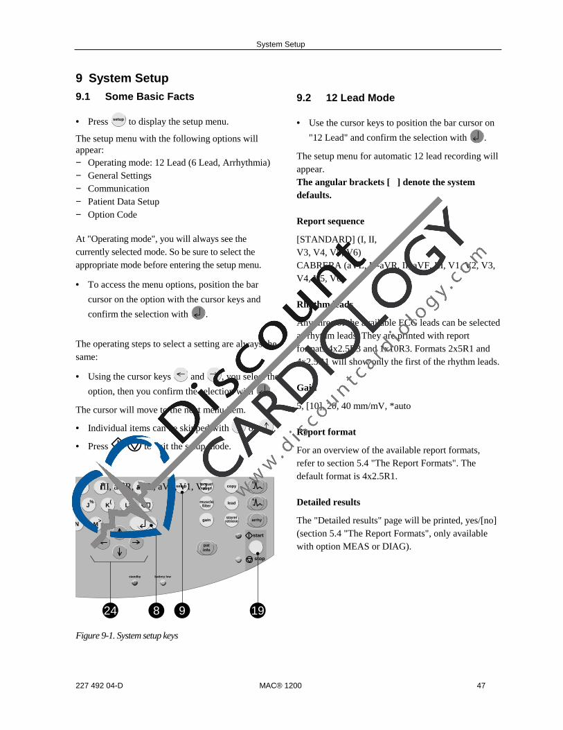
System Setup
227 492 04-D MAC® 1200 47
9 System Setup9.1 Some Basic Facts
• Press setup to display the setup menu.
The setup menu with the following options willappear:− Operating mode: 12 Lead (6 Lead, Arrhythmia)− General Settings− Communication− Patient Data Setup− Option Code
At "Operating mode", you will always see thecurrently selected mode. So be sure to select theappropriate mode before entering the setup menu.
• To access the menu options, position the bar
cursor on the option with the cursor keys and
confirm the selection with .
The operating steps to select a setting are always thesame:
• Using the cursor keys and , you select the
option, then you confirm the selection with .
The cursor will move to the next menu item.
• Individual items can be skipped with or .
• Press to exit the setup mode.
N<
M>
L)
XK(
J%
U7 I
8O
9P
0
start
stop
arrhy
patinfo
store/retrieve
lead
copysetup
gain
format/speed
musclefilter
12
6
standby battery low
199824
Figure 9-1. System setup keys
9.2 12 Lead Mode
• Use the cursor keys to position the bar cursor on
"12 Lead" and confirm the selection with .
The setup menu for automatic 12 lead recording willappear.The angular brackets [ ] denote the systemdefaults.
Report sequence
[STANDARD] (I, II,
III, aVR, aVL, aVF, V1, V2,
V3, V4, V5, V6)CABRERA (aVL, I, -aVR, II, aVF, III, V1, V2, V3,V4, V5, V6)
Rhythm leads
Any three of the available ECG leads can be selectedas rhythm leads. They are printed with reportformats 4x2.5R3 and 1x10R3. Formats 2x5R1 and4x2.5R1 will show only the first of the rhythm leads.
Gain
5, [10], 20, 40 mm/mV, *auto
Report format
For an overview of the available report formats,refer to section 5.4 "The Report Formats". Thedefault format is 4x2.5R1.
Detailed results
The "Detailed results" page will be printed, yes/[no](section 5.4 "The Report Formats", only availablewith option MEAS or DIAG).

System Setup
48 MAC® 1200 227 492 04-D
Muscle filter/AC line filter
Elimination of muscle artifact and AC line interfer-ence.Default: muscle filter [No], AC line filter [Yes]
Note
Please note that filters may suppress diagnostically
relevant portions of the signal, because they limit the
transmission range. Filters should therefore only be
enabled if necessary.
Filter frequency
Cut-off frequency of the muscle filter ([40 Hz],20 Hz).The frequency range is indicated in the lower marginof the recording strip."0.08 - 40 Hz" (40-Hz muscle filter enabled)"0.08 - 20 Hz" (20-Hz muscle filter enabled)"0.08 - 150 Hz" (muscle filter off).
Manual copy to
When the copy key is pressed, the unit will print acopy of the ECG [EKG] or send the ECG to a HOSTsystem (MUSE CV Information System).
No. of copies
If you do not want to print the ECG, but only collectdata, select "0" (message on display "REC OFF").When a number greater than 1 is selected, multiplecopies of the reports will be printed. Default: [1]
Autosave ECG (only with MEMO option)
After report generation, the ECG will or will not beautomatically saved to the internal memory (yes,[no]).
Delete ECG after Transmission(only with MEMO option)
ECGs that were successfully sent to a host systemvia the RS232 interface will be cleared from therecorder memory (yes, [no]).
If this menu item is set to "yes" and ECGs havealready been sent from the recorder memory, theseECGs will be deleted after the next transmission of astored ECG.
Configuration of the 12SL Interpretation
Use screening criteria
The screening criteria can be enabled or disabled.Default: [disabled]
Suppress "normal" statement
If you select 'Yes', the interpretation statement"normal ECG" will not be shown.
Suppress "abnormal" statement
If you select 'Yes', the interpretation statement"abnormal ECG" will not be shown.
Interpretation
Default: [Yes]. If you select 'No', 12 SL interpreta-tion results will not be generated nor shown.
Print Interpretation
Only available if "Interpretation" is set to "Yes".
Default: [Yes]. The interpretative statements areprinted on the reports. When you select "No", theinterpretation will not be printed, but it can be sentto the MUSE CV Information System.
Override function
When this function is enabled [yes], the recorderwill print in 12 Lead Mode, even when not allelectrodes are applied or do not supply a goodsignal.When electrodes are disconnected, a messageinforming the user of poor signal quality will beprinted on the recording.
Furthermore, systems with interpretation capabilitywill print a message indicating that the measurementresults and interpretation may be incorrect.

System Setup
227 492 04-D MAC® 1200 49
9.3 6 Lead Mode
• Use the cursor keys to position the bar cursor on
"6 Lead" and confirm the selection with .
The setup menu for continuous recording of 6 leadswill appear.
Report sequence
1. [STANDARD] (l, II,
III, aVR, aVL, aVF, VI, V2,
V3, V4, V5, V6)
2. CABRERA (aVL, l, -aVR, II, aVF, III, VI, V2,V3, V4, V5, V6)
3. SEQ. NO. 4 (here, users can define a customreport sequence):
• Position the cursor on "SEQ. NO. 4".
• Press setup .
The display shown in Figure 9-2 will appear.
Figure 9-2. Creating a custom report sequence
• Press .
The cursor will move to the position for entry of thelead in channel 1. Follow these steps, if you wish torecord aVR in channel 1, for instance:
• Enter AVR and confirm the entry with .
The cursor moves to the position for entry of thelead designation. AVR appears there as well.
• If you wish to enter another designation, you canoverwrite the default name (4 characters max.).
• Confirm your entry with and repeat theabove steps for channel 2, etc.
You can write over "SEQ. NO. 4" if you wish toenter another name for the report sequence.
Gain
*auto, 5, [10], 20, 40 mm/mV; with "*auto", the unitwill automatically determine the appropriate gainsetting for the 6 simultaneous leads.
Speed
Changes the writer speed. Default: [25 mm/s]
Muscle filter/AC line filter
Elimination of muscle artifact and AC line interfer-enceDefault: muscle filter [No], AC line filter [Yes]
Filter frequency
Cut-off frequency of the muscle filter ([40 Hz],20 Hz).The frequency range is indicated in the lower marginof the recording strip."0.08 - 40 Hz" (40-Hz muscle filter enabled)"0.08 - 20 Hz" (20-Hz muscle filter enabled)"0.08 - 150 Hz" (muscle filter off).
Anti-drift system (ADS) (cubic spline)
In case of wandering baselines, the anti-drift systemrestores the baseline to its original position (signaldelay with ADS approx. 2 s). Default: [No]
Start at queue mark
Before each recording, the recorder advances thepaper to the beginning of a new page (yes, [no]).

System Setup
50 MAC® 1200 227 492 04-D
9.4 Arrhythmia Mode
• Use the cursor keys to position the bar cursor on
"Arrhythmia" and confirm the selection with .
The arrhythmia mode menu will appear.
Report sequence
[STD_C]: V1, V2, V3, V4, V5, V6STD_RED: I, II, III, V2, V4, V6STD_LI: I, II, III, aVR, aVL, aVFCABR_LI: aVL, I, -aVR, II, aVF, IIIHIGH_C: V1’, V2’, V3’, V4’, V5’, V6’(C = chest leads, RED = reduced number of leads, LI= limb leads)
Gain
*auto, 5, [10], 20, 40 mm/mV; with "*auto", the unitwill automatically determine the gain setting.
Muscle filter/AC line filter
Elimination of muscle artifact and AC line interfer-enceDefault: muscle filter [No], AC line filter [Yes]
Filter frequency
Cut-off frequency of the muscle filter ([40 Hz],20 Hz).The frequency range is indicated in the lower marginof the recording strip."0.08 - 40 Hz" (40-Hz muscle filter enabled)"0.08 - 20 Hz" (20-Hz muscle filter enabled)"0.08 -100 Hz" (muscle filter off).
Trend rec.
The slow trend recording of 5 mm/s automaticallybegins at program start ( [no]/yes).
Arrhythmia data
The recorder will document arrhythmias in thefollowing situations:
- each time an arrhythmia occurs- each time an arrhythmia occurs that is different
from the preceding event- arrhythmias are not documentedall, [unequal], no.
Episodes
Final report includes episode report, with episodeslisted by one of the following criteria
- in chronological order- according to priorities (see table 7-1)- ventricular beats only- no episodes[chron.], prio., ventr., no

System Setup
227 492 04-D MAC® 1200 51
9.5 General Device Settings
Ordering / Referring Physician / Technician
In the field at left, you see the last name of thephysician or technician selected as the default name.When selecting "other", a menu displays where youcan enter up to 10 names (2-digit ID number, firstname, last name). The default name (and ID) isautomatically selected at power-up.The "Referring Physician" is only relevant if yousend ECGs to the MUSE CV system. This name willnot be annotated on the ECG recording. Press the
key to exit the menu.
Institution Name
The name entered here will be printed on each reportpage.
Cart #
Enter any number between 1 and 9999 to identifythe cart (local system). The cart # entered here is thedefault number that appears in "Patient Data".Default: [1]
Site #
Enter any number between 1 and 255 to identify theMUSE CV Information System to which the ECGswill be sent. The site # entered here is the defaultnumber that appears in "Patient Data".Default: [1]
Location #
Enter any number between 1 and 600 to identify thelocation of the sending system. The location #entered here is the default number that appears in"Patient Data".Default: [1]
Date/Time
Enter date and time (enter 4 digits for the year).
Lead fail beep
Indicates when electrodes are not properly applied ordisconnected (yes/[no]).
High HR beep
An audible signal sounds when the heart rateexceeds a limit value (yes/[no]) (only in 6 Lead andArrhythmia Modes). The limit value (220 - age) canbe changed manually.
Lead labels
[AAMI] codes: RA, LA, RL, LL, V1 to V6 orIEC codes: R, L, F, N, C1 to C6
Date
Format: [month/day/year] or day.month.year
Time
Time format [12] hours (am/pm) or 24 hours
Units
Units of measurement for the patient's height andweight: [in/lb] or cm/kg
Mains
AC line frequency (USA [60 Hz], Europe 50 Hz)
LCD light off after
If operating controls are not activated within theselected period of time the display backlightingautomatically switches off (system default [5 min],adjustment range l to 99 min).
Default mode
This is the operating mode the unit defaults to afterpower-up: [12 Lead], 6 Lead, Arrhythmia
Language
Select the language for user interface and printouts.

System Setup
52 MAC® 1200 227 492 04-D
Enable password protection
Select "yes" to protect the setup menu with apassword. You will be asked to enter a password andto repeat it. The password protection is then active.To change the password (only possible whenpassword protection is active)
− select menu item "Enable password"− enter the old password− enter the new password− repeat the new password
Test DATA
Used for demonstration purposes (yes). It must beset to [no] for proper clinical use.
Restore defaults
Selecting "Yes" will restore the default setup(including the defaults of the three operatingmodes).The resting ECG analysis system must be switchedoff (standby) and on again for the new settings tobecome effective.
Print Setup Lists
Selecting "yes" will display a menu with allavailable setup lists.− all lists− System Setup / Communication / External
Devices / Patient Data Setup− 12 Lead− 6 Lead− Arrhythmia
9.6 Communication
Protocol
The recorder offers two communication protocols:"CSI" (Client Server Interface) and A5.The CSI protocol supports the transfer of restingECGs from the resting ECG analysis system to aMUSE CV system.With the "A5" protocol, the 10-second resting ECGcan be transmitted to CardioSys and CardioSoft.
Baud rate (HOST)
Transmission rate for the selected protocol. Werecommend the default setting of [19200 baud].
Modem
Select the modem type. You can choose among thestandard modems MultiTech (MT 19.32, 56.6), Elsa28.8, Elsa 33.6, Elsa 56.6 and a user-definedmodem.
When using one of the standard modems, all youhave to enter is
− the dial mode (pulse or tone, depending on yourtelephone network)
− the telephone number (28 digits max.)− the number to access the public telephone
network (e.g. "0").
For a user-defined modem, enter
− the telephone number (28 digits max.)− the init string (20 characters max.) (see modem
operator's manual)− the dial string (20 characters max.) (see modem
operator's manual)− the hangup mode (20 characters max.) (see
modem operator's manual)
---------------------------------------------------------------------------------------------------------------------------------------
The master password overriding all other passwords is
SYSTEM
Use this password if you cannot remember your own password.

System Setup
227 492 04-D MAC® 1200 53
9.7 Patient Data
The patient data menu can be set up to meetindividual requirements. If you do not want to enterblood pressure readings, for instance, you canremove the corresponding prompts:
• Use the cursor keys to position the bar cursor on
"Setup Patient Data" and confirm the selection
with .
The patient data setup menu will appear.
• Select "no" for prompts that you want to remove
from the dialog.
Items - Last name- First name- Date of birth- Patient ID
cannot be removed.
Items - Height- Weight- Diastolic BP- Systolic BP- Referring Physician- Medication- Comments- ID required- Secondary ID- Secondary ID required- Last name required- First name required- Extra Questions (Prompt 1 through Prompt 4)
are disabled. They can be enabled from the patientdata setup menu.
"Required" Data Fields
If, for one of the data fields
− ID required− 2nd ID required− Last name required− First name required
you choose "yes", an ECG can be recorded in 12Lead Mode only if the corresponding patient data isentered.
Prompt 1 to 4
You can enter any text here (10 characters max.).When you have entered the text, you can select theformat of the response field. There is a choice of 3formats:
− alphanumeric field (17 characters max.)− only numbers (9 numbers max.)− yes or no
• To exit the menu, press .

System Setup
54 MAC® 1200 227 492 04-D
9.8 Option Code
In this menu you enter the option codes to enable anumber of optional software functions. Therespective option becomes active after you haveentered the code number. The code numbers arelisted on the option code sheet supplied with thedifferent software options.
• In the setup menu, position the bar cursor on
"Option Code" and confirm the selection with
.
The option code menu appears. There is a choice of6 options:
MEAS: measurement of the 10-second resting ECG
DIAG: measurement and interpretation of the 10-second resting ECG
MEMO: program for storage of up to 40 resting ECGs
C100: activates the three options MEAS, DIAG, MEMO for a maximum of 100 ECGs
C500: activates the three options MEAS, DIAG, MEMO for a maximum of 500 ECGs
EVAL: activates the three options MEAS, DIAG, MEMO for a maximum of 4 weeks
• Position the bar cursor on the option you wish toactivate.
• Enter the 12-digit code number from thekeyboard and confirm the entry with .
The unit will accept the entered number only if itcorresponds to the unit's serial number. The serialnumber is indicated at the top of the menu (Ser.No.= xxxxxxxxx). This number must be the same asprinted on the nameplate (back of the device).When you enter the code number for DIAG andMEMO, the fields for C100, C500 and EVAL willdisappear.
• Exit the menu with .
9.9 ECG Transmission via Modem
• Select the 12 Lead Mode and press setup .
• Press to display the setup menu for the 12Lead Mode.
• Use the cursor keys to position the bar cursor on"Manual copy to HOST" and confirm the selec-tion with ([HOST]).
• Press to clear the setup menu.
• Use the cursor keys to position the bar cursor on"Communication" and confirm the selection with
.
Selecting the Communication Protocol
• Using the cursor keys, position the bar cursor on"Protocol". Select the protocol CSI to send datato a MUSE CV system, or select A5 if you willsend data to CardioSys/CardioSoft.
• Use the cursor keys to position the bar cursor on"Modem, other" and confirm the selection with
.
• Choose the modem you use from the list andconfirm the selection with .If your modem is not included in the list, select"other" and enter the required modem commands(see also "Modem Setup" in section 5.5).
• When you have selected a standard modem,position the bar cursor on "Dial mode" and selectthe appropriate mode.
• Enter the telephone number of the receiving
modem and the number to access the public
telephone network and terminate the setup with
.

System Setup
227 492 04-D MAC® 1200 55
9.10 Direct ECG Transmission
• Select the 12 Lead Mode and press setup .
• Press to display the setup menu for the 12Lead Mode.
• Use the cursor keys to position the bar cursor on"Manual copy to HOST" and confirm the selec-tion with ([HOST]).
• Press to clear the setup menu.
• Use the cursor keys to position the bar cursor on"Communication" and confirm the selection with
.
• Select the same baud rate as at the receivingmodem (9600, 19200, 38400, 57600).
Selecting the Communication Protocol
• Using the cursor keys, position the bar cursor on"Protocol".Select the protocol CSI to send data to a MUSECV system, or select A5 if you will send data toCardioSys/CardioSoft.
• Use the cursor keys to position the bar cursor on"Modem, none" and confirm the selection with
.

Loading Chart Paper
56 MAC® 1200 227 492 04-D
Z;X:
C/
V,
B.
N<
M>
L)
X
K(
J%
H*
G+
F-
D=
S?
A!
alt
Q1 W
2 E3
R4
T5 Y
6 U7
I8O9
P0
setup
onoff
MAC 1200
Figure 10-1. Opening the paper compartment door
Z;X:
C/
V,
B.
N<
M>
L)
X
K(
J%
H*
G+
F-
D=
S?
A!
alt
Q1 W
2 E3
R4
T5 Y
6 U7
I8O9
P0
setup
fo
stand
onoff
MAC 1200
Figure 10-2. Inserting the new Z-fold pad
Z;X:
C/
V,
B.
N<
M>
L)
X
K(
J%
H*
G+
F-
D=
S?
A!
alt
Q1 W
2 E3
R4
T5 Y
6 U7
I8O9
P0
start
stop
arrhy
patinfo
store/
retrieve
lead
copy
setup
gain
format/
speed
muscle
filter
12
6
standby
battery low
onoff
MAC 1200
Figure 10-3. Guiding the leading paper edge overthe guide roller
Z;X:
C/
V,
B.
N<
M>
L)
X
K(
J%
H*
G+
F-
D=
S?
A!
alt
Q1 W
2 E3
R4
T5 Y
6 U7
I8O9
P0
start
stop
arrhy
patinfo
store/
retrieve
lead
copy
setup
gain
format/
speed
muscle
filter
12
6
standby
battery low
onoff
MAC 1200
Figure 10-4. Closing the paper compartment door
10 Loading Chart Paper
• Switch on the recorder.
• Pull up the handle of the paper door and fold itout (Figure 10-1).
• Remove the cardboard backing of the previouspaper pad.
• Remove the cardboard from the top of the newpad and place the pad, including the cardboardbacking at the bottom and with the arrow point-ing towards the unit, into the paper compartment(Figure 10-2).
• Pull the top sheet out of the compartment andguide it around the guide roller (Figure 10-3).
• Holding the leading edge of the paper in placebetween the two markers on the recorder, closethe paper door (Figure 10-4). Ensure that it locksinto place on both sides.
When inserting an already started Z-fold pad, thegrid side must face up and the first fold must pointtowards the paper compartment.

Loading Chart Paper
227 492 04-D MAC® 1200 57
Note
− Having inserted a new paper pad, be sure to
acknowledge the "end of paper" message with
, not with .
− When closing the paper door, take care that itlocks into place on both sides.
− There is a window in the paper door that allowsyou to look inside the compartment and checkthe paper supply.
− Use only the original HELLIGE CONTRAST®chart paper or the GE Marquette thermal paperwith queue marks or holes. This paper has a spe-cial coating that prevents- contamination and debris collecting on the
printhead and- electrostatic build up.
- Furthermore, the thermosensitive layer and theprinthead characteristics are exactly matched.Using other paper may result in recordings ofpoor quality.Moreover, the printhead may wear out prema-turely. Use of other paper voids the warranty.
End-of-Paper Indication
A stripe marks the last 10 pages of the Z-fold pad.
When the writer runs out of paper during a record-
ing, it will emit an audio signal and displays the
message "End of paper or paper jam, if OK, press
".
• Insert a new paper pad and acknowledge the
message with .
Aging Stability
The standard ECG writer paper CONTRAST isdesigned to guarantee full contrast for a periodbetween 3 and 5 years if it is handled as describedbelow before and after recording:
• Store the paper in suitable rooms at a temperaturebetween 18° and 24° and a relative humiditybetween 40 % and 60 %.
• Avoid direct contact of the paper with− carbon and carbonless forms− chart papers and adhesives containing tributyl
phosphate, dibutyl phthalate, or any other or-ganic solvents
− document protectors, envelopes, and sheetseparators containing plasticizers.Caution: The above components may also befound in recycled papers.
− solvents or solvent-based products containingalcohols, ketones, esters, or other substancesfrom this chemical group.
• We recommend archiving ECG recordings on ourECG filing cards only (P/N 217 043 03).
• If longer storage periods are required, we suggestusing our ARCHIVIST 30 chart paper (imagelegibility up to 30 years) or other image storagetechnologies.
A stripe marks the last 10 pages of the Z-fold pad.

Cleaning, Disinfection and Maintenance
58 MAC® 1200 227 492 04-D
11 Cleaning, Disinfection and Maintenance
11.1 Cleaning and Disinfecting theRecorder Housing
Warning
Before cleaning or disinfecting the device, discon-
nect it from the power line.
• Clean the recorder housing with a moist cloth. Donot let liquid enter the device. All cleaning agentsand disinfectants that contain alcohol and arecommonly used in hospitals are suitable, but donot use disinfectants on a phenol base or peroxidecompounds.
11.2 Cleaning and Disinfecting thePatient Cable
• Disconnect the cable from the recorder beforecleaning or disinfecting it. When disconnectingthe cable, be sure to pull on the connector, not onthe cable.
• Clean the cable by rubbing it down with a clothmoistened with soap water. Use a disinfectant fordisinfection. Do not immerse the cable in liquid.
11.3 Cleaning and Disinfecting theElectrodes
In addition to the information given in this manual,observe the instructions for use of the respectiveelectrode types.
• Discard disposable adhesive electrodes immedi-ately after use to prevent that they are reused.
• Clean reusable electrodes immediately afterremoving them from the patient.
• Peel off the adhesive foil before cleaning theelectrodes (rests of the adhesive can be removedwith benzine).
• Then use warm water and a small brush to cleanthe electrodes of cream or gel. Do not use pointedor sharp objects for cleaning.
• Disinfect the electrodes with alcohol-freedisinfectant. Ensure that connectors and socketsdo not become wet.
• The only approved sterilization method is gassterilization.Frequently sterilizing the electrodes with ethyl-ene oxide gas reduces the life of the plasticmaterial.

Cleaning, Disinfection and Maintenance
227 492 04-D MAC® 1200 59
11.4 Maintenance
Checks before each use
Before each use, visually inspect the device, theleads and electrodes for signs of mechanical damage.
If you detect damages or impaired functions thatmay adversely affect the safety of the patient or user,do not use the device before it has been repaired.
Technical Inspections
For safety, the devices require regular maintenance.To ensure functional and operational safety of theMAC 1200 units, Technical Inspections should becarried out on an annual basis.
These checks should be performed by persons withadequate training and experience.
The checks can be carried out by GE Marquettewithin the framework of a service contract. Theinspections include the following checks:
• Visually inspect the device and the accessoriesfor signs of mechanical damage that may impairthe device functions.
• Check that the device labeling relevant for safetyis legible.
• Run a performance test as described in theoperator's manual.
• Measure the resistance of the protective earthconductor and the equivalent leakage current peryour national regulations.
The device does not require any other maintenance.
Disposal at the End of Its Service Life
Note
At the end of their service life, the device described
in this manual and its accessories must be disposed
of in compliance with the applicable local waste
control regulations. If you have questions regarding
the disposal of the product or of accessories, please
contact GE Marquette or its representatives.

Troubleshooting
60 MAC® 1200 227 492 04-D
12 Troubleshooting
Symptom Cause Remedy
Periodic superimposition of ACline interference (60 Hz) (Figure12-1)
interference from the power line Ground bed, verify position of theleadwires, switch on AC line filter
Superimposition of irregular ACline interference (Figure 12-2)
Muscle artifact caused bypatient movements, hiccup,coughing
The patient should be warm enoughand resting comfortably (placecushions under arms and knees).Comfort patient or distract patient'sattention, enable muscle filter (20 Hz /40 Hz), if necessary.
The printed date and time areincorrect
Built-in lithium battery isdepleted. The battery has a lifeof approx. 5 years
Notify service to check and/or replacebattery
The green standby indicator 23does not light up, although therecorder is connected to thepower line
Defective AC power adapter orfuse
Notify service to check and/or replacefuse
The recorder does not write overthe entire paper width
Paper compartment not properlyclosed
Paper door must lock into place onboth sides
In 12 Lead Mode, the recorderdoes not stop and continues tofeed paper. This does nothappen in 6 Lead Mode.
The paper pad was inserted thewrong way round so therecorder cannot detect the cuemark
Insert the paper pad as instructed
Recorder does not start after
activation of the key, orthe recording is aborted.
Unit operated on battery power:battery discharged
Connect recorder to the power line.After a few minutes, the recorder isable to resume operation. Alwaysconnect recorder to the power linewhen the battery low indicator 22lights up. The battery capacity dependson age, temperature and charge level(chapter 3 "Putting the Recorder intoOperation").
No recording in 12 Lead Mode Failure of at least one electrode Check all electrodes or enable Overridefunction (section 9.2 "12 Lead Mode").
Paper jam Open paper compartment and removedjammed sheet,place beginning of paper between themarks, close paper compartment and
press .

Troubleshooting
227 492 04-D MAC® 1200 61
Figure 12-1. Regular AC line interference
Note
In the presence of very strong AC line interference
in all leads, the thermal printhead may interrupt
the recording. Activate the AC line filter (60 Hz) in
these situations.
Figure 12-2. Irregular AC interference

Technical Specifications
62 MAC® 1200 227 492 04-D
13 Technical Specifications
Recording
Direct recording of waveforms and alphanumericcharacters with rectangular coordinates by meansof thermal-array printhead printing on thermosen-sitive paper.
• 3 or 6 recording channels, or 12 in 12 LeadMode, overlapping
• baseline pitch 3 channels: 62 mm (arrhythmia) 6 channels: 31 mm (6 Lead)12 channels: 16 mm (12 Lead.)
• writing width 200 mm max.
• annotation of recorder settings, date, time andentered patient name in the margin of the re-cording strip
• with appropriate software, documentation ofanalysis results in the respective operatingmode
• resolution of the recording:vertical 8 dots/mmhorizontal 25 µm at 25 mm/s
Printer paper
HELLIGE CONTRAST® Z-fold pad , 150 pagesper pad, equivalent to a chart length of approx. 45m
paper width:8.5 inch
sheet length: 11 inch
To prevent damage to the printhead use only theoriginal HELLIGE CONTRAST® paper or the GEMarquette thermal paper with queue holes ormarks.
Paper transport
• paper speed5-25-50 mm/s, key selectableerror limits at 25 and 50 mm/s, typ. ±l%
at 5 mm/s, ±10% max.
• At paper end, the recorder emits an audio signaland stops recordingthe last pages of the pad bear a colored stripe inthe lower margin
Membrane keypad
Pushbuttons with tactile feedback
• function keys for all routine operations
• alphanumeric keyboard for entry of text
Display
graphics display with 24 x 40 characters, contrastadjustment
resolution of 320 x 240 pixels with displaybacklighting
Indicators (LEDs)
For mains power, battery status and start/stopfunction
Automatic functions
They assist and facilitate operation by
• automatic control of lead selection, paper feed,calibration (configurable)
• report formatting (configurable)
• automatic baseline adjustment
• anti-drift system (cubic spline) compensatingfor polarization voltage fluctuations (configur-able)

Technical Specifications
227 492 04-D MAC® 1200 63
Detection of pacer pulses
• pulse length between 0.1 and 2.5 ms
• pacer pulse marker independent of pulsepolarity
• pulse amplitude between ± 5 mV and ± 700 mV
Heart rate indication
derivation of the heart rate from all ECG signals
• display range between 30 and 300 bpm
• display update with every heart beat, maximumevery 2 seconds
Signal inputs
isolated patient signal input, IEC type CF, high-voltage protection for all lead connections andneutral electrode, interference compensation vianeutral electrode, monitoring for open leads
• electrode connections for RA, LA, LL, LA, Vlto V6
• input impedance for differential signalsbetween any two electrode connections> 10 MΩ at 10 Hz
• input impedance for common-mode signalsreferred to neutral electrode > 50 MΩ up to60 Hz
• dynamic range for differential signals betweenany two electrode connections for AC voltage±10 mV, for superimposed DC voltage (polari-zation voltage) ±600 mV
• dynamic range for common-mode signalsreferred to neutral electrode ±l V, referred tochassis 263 V AC (rms)
• quiescent input current via any electrodeconnection for l kΩ termination referred toneutral electrode < 50 nA
• patient leakage current (rms values) accordingto IEC, class CF: in normal condition < 10 µA,
in single-fault condition (e.g. patient in contactwith line voltage) < 20 µA
• non-destructive range for lead-electrodeconnections and the neutral electrode connec-tion referred to neutral electrode ±50 V, re-ferred to chassis ±1500 V
• pulse voltage resistance of all lead electrodeconnections and of the neutral electrode con-nection referred to chassis (either polarity, e.g.defibrillation) 5000 V
• monitoring of each electrode for open leads:RA, LA, LL, RL, V1, V2, V3, V4, V5, V6audio signal at printer start
Data interface
one serial RS232 interface for exchange of datawith suitable external devices and softwarehandshake
RS232 interface (standard V.24 interface):
• input voltage range. ± 15V max.
• output voltage range ±5 V min.
• interface protected from electrostatic dischargefor ±10 kV max.
Transfer of ECGs with the CSI protocolbetween the MAC 1200 and the following units
MUSE CVIS SW version 004A and laterMAC 5000 SW version 001B and laterMAC VU SW version 002A and laterMAC 1200 SW version V5.01 and later
Receiving data with the CSI communicationprotocol from the following units
CardioSmart SW version V4.21 and laterCardioSmart ST SW version V4.21 and later
Sending ECGs to the following units with theA5 protocol
CardioSys / CardioSoft SW version V1.0 and later

Technical Specifications
64 MAC® 1200 227 492 04-D
Pin assignment of data port
235
68
Remote start (hardware)
Paper feed via remote control connection(depending on selected operating mode). Externalmake contact referred to chassis via circuitreference:
• source impedance Ri < 300 Ω
• contact dwell > 100 ms
• non-destructive load ± 10 V
• ESD interface protection up to ± 10 kV
Signal Transmission
Patient input to recording
After lead formation and digitization simultaneoustransmission of all electrode signals to the digitalprocessing system; muscle filter, AC filter, pacingpulse identification, automatic or manual sensitiv-ity adjustment, automatic baseline adjustment anddrift compensation by means of the anti-driftsystem (A.D.S.) can be enabled or disabledsimultaneously for all channels; digital output ofprocessed signals via thermal-array printhead.
• low cut-off frequency (-3 db limits) 0.08 Hz,equivalent to a time constant of 2.04 s
• high cut-off frequency (3 dB limits) operatingmode: 12 Lead, 6 Lead 150 Hz (IEC/AHA)operating mode: Arrhy 100 Hz (IEC)
• signal sampling rate: 1000/s
• resolution, referred to the input 5 µV
• output rate to recorder 2000/s
• for all leads, gain adjustment in four steps:40-20-10-5 mm/mV
• with active muscle filter (low-pass characteris-tic) 3-dB drop of the amplitude frequencyresponse at approx. 40 or 20 Hz
• with active AC line filter detection andcompensation of periodic 50 or 60 Hz fre-quency components (depending on recordermodel) attenuation >40 dB
• non-linear distortion below values specified inIEC and AHA recommendations
• coincidence error limits between any twochannels ±0.5 mm
• detection of pacer pulses in V2 or other V leadsand marking in all channels for signals referredto patient input:duration ≥ 0.1 ms, amplitude > 5 mV
• noise in the signal transmission path belowvalues specified in IEC and AHA requirements:≤ 2.5 µV rms
• common-mode rejection for 50 or 60-Hz signals(depending on recorder model) with AC filterswitched on >140 dB
ECG calibration
automatic recording of a defined voltage step,valid for all channels
• calibration voltage, referred to ECG signalinput: l mVcalibration pulse width on recording dependson paper speed25 mm/s 5 mm50 mm/s 10 mm5 mm/s l mm
2 RXDE
3 TXDE
5 circuit reference
6 modem supply
8 remote start

Technical Specifications
227 492 04-D MAC® 1200 65
Automatic ECG gain adjustment
The gain automatically adapts to the incomingsignal. The maximum amplitude of the lead groupor of all leads determines the gain setting.
• automatic adjustment range 5 to 40 mm/mV
• amplitude range (6 channels) 18 to 31 mm
Baseline
automatic adjustment of the baseline to the optimalrecording range, in dependence of the signalamplitude
Anti-drift system (ADS) (cubic spline)
automatic compensation of baseline fluctuationscaused by polarization voltage fluctuations at thelead electrodes (delay in recording: 4.2 s)
ECG storage
in 12 Lead Mode, storage of up to 40 ECGs
• stored ECGs can be deleted (individually or allin one pass), printed, transferred, and patientdata can be edited
• when memory is full user is informed of thepossible actions
Blocking
rapid charge reversal of the coupling capacitors inthe preamplifiers after electrode application,ensures that the baseline is quickly restored to itsoriginal position after overranging
Electrode monitoring
audible and visual indication on the LCD ofdisconnected electrodes or line break; each singleelectrode is monitored
Text input
patient and user data as well as comments can beentered via the panel keyboard and are annotatedon the recording strip
Copy function
after ECG recording in 12 Lead Mode, copies ofthe ECG can be printed from memory and/ortransferred to a MUSE CV system (configurable)
Test
automatic performance test upon power up,including verification of the signal path starting atthe signal input
stored test ECG data for demonstration of thedevice functions
Power supply
from the power line or from a built-in rechargeablebattery, automatic switchover; automatic batterycharging during line-power operation fromintegrated AC adapter module
Mains operation
• instrument design in protection class Iaccording to IEC 60601-1
• Rated voltage range 95 to 240 V
• operating voltage range 85 to 264 V,49 to 65 Hz
• rated current: 0.2 to 0.6 A
• fuse 2 x T1.25A, 5x20
• typical power consumptionbattery charging 14 W
• max. power consumption 29 W
Battery operation
• type: nickel-cadmium
• rated battery voltage18 V

Technical Specifications
66 MAC® 1200 227 492 04-D
• rated battery capacity 1.3 Ah
• fully charged battery sufficient for up to 5012 Lead Mode, 1-page ECGs, if unit is onlyswitched on to record the ECGs
• battery charge time approx. 4 hours(min. charge time for one 12 Lead Mode ECG:10 minutes)
• battery life approx. 2 to 3 years, replacement byservice only
• lithium battery for built-in clock, battery lifeapprox. 5 years, replacement by service only
Operational readiness
After successful self-test, approx. 10 s after power-up
Operating position
horizontal
Environment
Operation
• temperature between 50 and 104 °F
• relative humidity between 25 and 95%
• atmospheric pressure between 700 and1060 hPa
Transport and storage
• temperature between -22 and +140 °F (includ-ing battery)
• relative humidity between 25 and 95%
• atmospheric pressure between 500 and1060 hPa
Recorder dimensions
• width 14.5 in.
• height 3.7 in.
• depth 12.6 in. (incl. handle)
Weight
• approx. 12.3 lb (with battery)

Entering Special Characters
227 492 04-D MAC® 1200 67
Appendix
Entering Special Characters
The following special characters can be entered bymeans of the appropriate keystroke combination.
charac-ter
keystroke combination
\ Alt + Q
@ Alt + W
# Alt + E
$ Alt + R
& Alt + Y
¿ Alt + D
— Alt + F
Ç Alt + G
Å Alt + K
Ü Alt + L
î Alt + X
Ñ Alt + C
" Alt + V
Ø Alt + B
Ö Alt + N
Ä Alt + M
Á Alt + I, then A
É Alt + I, then E
Í Alt + I, then I
Ó Alt + I, then O
Ú Alt + I, then U
À Alt + O, then A (enter È, Ì, Ò, Ù in thesame manner)
 Alt + P, then A (enter Ê, Î, Ô, Û in thesame manner)
ÿ Alt + U, then Y (enter Ï, Ä, Ö, Ü in thesame manner)
à Alt + H, then A (enter Ñ, Õ in the samemanner)
Ð Alt + A
Æ Alt + J
Z Alt + T, then Z
Š Alt + T, then S
¡ Alt + X
Index
68 MAC® 1200 227 492 04-D
Index
112 Lead mode, brief operating instructions 3812 Lead mode, system defaults 2612 Lead mode, system setup 4712SL interpretation, configuration 48
66 Lead mode, brief operating instructions 416 Lead mode, system defaults 396 Lead mode, system setup 49
AAC line frequency 51AC line interference 48, 60Activating options 54Aging stability (recordings) 57Anti-drift system 23, 49Arrhythmia codes 45Arrhythmia mode 42Arrhythmia mode, brief operating instructions 45Arrhythmia mode, system defaults 42Arrhythmia mode, system setup 50Arrhythmia recording 50Automatic baseline adjustment 23
BBattery, charging 16Baud rate 52Birthdate, enter 25Brief operating instructions, 12 Lead mode 38Brief operating instructions, 6 Lead mode 41Brief operating instructions, arrhythmia mode 45
CCart number, enter 51Cart to cart communication 37Caution, definition 12Cleaning 58Connecting external equipment 19Contrast, adjustment 17Controls, overview 10Cubic spline 23
DDanger, definition 12Date 51Detailed results 31, 47Disinfection 58Display backlighting 51Disposal of the device 59
EECG recording during defibrillation 46ECG transmission (modem) 32ECG transmission to MUSE CV system 34, 35ECG transmission via modem 32ECGs, receive 36Electrode placement 22End of paper while printing 29End of writer paper 57Entering patient data 24Environment, operation 66Environment, storage and transport 66Event episodes 50External equipment, connection 19
FFinal report 44, 50Functional description 9
GGeneral device settings 18General information 6General settings, system setup 51
HHeart rate limit 41, 44HOST system 48
IID number, MUSE 51Indicators, overview 10Installation 17Intended use 9Interpretation, enable - disable 48Interpretation, print 48
LLanguage 51Lead fail beep 51Lead labels 51Limb lead electrodes, application 21Lithium battery 60Location number, enter 25, 51
MMains connection 17Maintenance 58Master password 52Medication 25Memory (optional MEMO function) 29Memory option 26Modem 32

Index
227 492 04-D MAC® 1200 69
Modem setup 37Muscle artifact 48Muscle filter 48MUSE CV Information System 19
OOption codes 3, 54Options, how to activate 54Options, overview 9Order number, enter 25Ordering physician 25Override function 48
PPacemaker patient 46Paper feed, automatic 49Paper jam 60Paper, inserting new pad 56Password protection (setup menu) 52Patient data setup 53Patient data, entry 24Patient ID, enter 25Patient name, enter 25Performance check 17Physician, referring, ordering 25, 51Power supply 16Prompts 53Protocols 52
RReceiving ECGs 36Recharging the battery 16Recording in 12 Lead mode 27Recording in 6 Lead mode 39Recording in Arrhythmia mode 43Recording problems 23Referring physician 25Report formats, 12 Lead mode 31Revision code 2Revision history 2
Room number, enter 25
SSafety information 12Saving ECGs 29Secondary patient ID, enter 25Self-test, abort 17Service parts, how to order 4Service requests, where to call 5Setup 47Site number, enter 51Software version 2Specifications 62Standard leads 22Supplies, how to order 4Symbols, explanation 11System defaults, 12 Lead mode 26System defaults, 6 Lead mode 39System defaults, arrhythmia mode 42System setup, 12 Lead mode 47System setup, 6 Lead mode 49System setup, Arrhythmia mode 50System setup, general settings 51
TTechnical specifications 62Technical support 4Test DATA 52Thorax electrodes, application 22Time 51Trend recording 50Troubleshooting 60
UUnits 51
WWarning, definition 12


