resources/enfield-bullet-workshop... · no liability can be accepted by Royal Enfield or the...
28
Transcript of resources/enfield-bullet-workshop... · no liability can be accepted by Royal Enfield or the...


Page Nos.
PREFACE, PRECAUTIONS GENERAL INSTRUCTIONS - l ROLJTINE MAINTENANCE -
TECHNICAL SPECIFICATIONS 350cc & 500cc 6-9
DESCRIPTlON OF ENGINE PARTS - 10- 13
DECARBONISING
SERVICE OPERATION - ENGINE ON F W E
SERVICE OPERATION - ENGINE - REMOVED FROM FRAME
G M BOX
FRAME REAR SUSPENSION
FRONT FORK [HYDRAULIC)
WHEELS
ADJUSTMENT OF BRAKES
TYRES - REMOVAL AND REPLACEMENT
IGNITION AND LIGHTING SYSTEM
WIRING D L A G W S
ELECIIUCAL CONNECTION DETAILS
CARBURETTOR
SERVICE LIMITS
TROUBLE SHOOTING
TORQUE VALUE CHART
SPECIAL TOOLS 101-106
METRlC CONVERSION TABLE 107

PREFACE -
We take pleasure in releasing this Maintenance Manual as a guide t - senice. Most of the servicing can well done by the average owner. N diagrammatic Sketches and photo illustrattons have been introduced for better understanding. However for an owner who feels uncertain of his ability to, undertake - any stripping and re-building for a major overhaul, we strongly reco work be done by an authorised 'ENFIELD DEALER/DISTRIBUTOR that the use of proper service maintenance tools and genuine Enfield best results. - Whilst every care is taken to ensure that the information in this manu no liability can be accepted by Royal Enfield or the publisher for 10s or injury caused due to errors or omissions in the informations given.
PRECAUTIONS AND GENERAt INSTRUCTIONS
Observe the following points without fail, when dismantling and reassembhg Motor-cycle parts.
- Be sure to replace packings, gaskets, circlips. '0' rings and cotter pins with new ones, for 'safe riding'. .
- Tighten bolts & nuts starting from the larger diameter ones to the smaller diameter and from inside to outside diagonally, with specffied tightening torque.
- Use always genuine spares and recommended grade of oils only.
When using a torque wrench for checking, always loosen the bolt or nut by half turn and then tighten to the specified torque. Never use torque wrench for loosening a bolt or nut.
L
B ~ . G SPARE PARTS n
When ordering spare parts for your Motorcycle it is advisable to deal direct with the Enfield official dealer/distributor, who should be able to supply most of the parts ex-stock. \
Always quote the Engine Number and Frame Number and description of part required. It is advisable to indicate the colour scheme especially while ordering parts for frame. side panels,tank, mudguards, etc., /

ROUTINE MAINTENANCE
Introduction
Periodic routine maintenance is a continuous process that commences immediately after the machine is used. It must be carried out at specified mileage recordings, or an a calendar basis if the machine is not used frequently. - -
Maintenance should be regarded as an insurance policy, to keep the machine in peak condition and to ensure long, trouble free service.
The various maintenance tasks are described under their respective mileage and period. The intervals between the various maintenance tasks serves only as a guide. A s the machine gets older or used under particularly adverse conditions, it would be advisable to reduce the period between each check.
For ease of reference each service operation is described in detail under the relevant heading. In order to c u t the routine maintenance tasks, a good selection of general workshop tools is ab~olutel~essential.
Included in the kit must be a range of m phillips head screw drivers and pair i f circlip
No special tools are required for the normal roufine maintenance tasks. The tools contained in the tool Mt supplied with every new machine will prove adequate for each task, or if they are not available, the tools found in the average household will usually suffice.

A daily check of the Motorcycle is essential both from mechanical and safety aspects. I t is a good idea to develop this checking procedure in a specific sequence so that It wtll ultimately become as instinctive as actually riding the machine. Done properly, this simple checking sequence will give advanced warning of impending mechanical failures and conditions which may jeopardize the safety of the rider.
- Clean the motorcycle with a clean cloth.
- Check engine oil leve1,using the dipstick provided in the oil tank cap. Maintain oil level upto 'H' mark. If necessary top up ofl to the required level.
- Check proper operations of all controls viz. clutch, accelerator, brakes, aI1 lights and horns.
- Check tyre pressure, with a pressure gauge. Cneck tyre pressure when the tyres are cold. It is worth purchasing a small pocket pressure gauge which can be relied upon, to give consistent readings than garage forecourt gauges which tend to be less dependable. ;; <G?i'air-.r.-*,6z7-.---.. as> G. x*2~;<p:p:>.;:.;:2?<:2:*-.-+<q2=s3@~*.: -P---- ;~~+X*?:~T+;.E%*~~~*- ,,,; -pT3-. ?!.. -:<-n-.&$.&zg - -. . -;$$,~g~@;gss~~:~gon@:3@Psr*~Rear G~~+z.2~a.42.G..-c ~ ~ ~ ~ ~ ~ ~ e 2 ~ z 2 ~ 2 ~ ~ - ~ ~ ~ v : L + g . ~ ~ ~ ~ ~ E 5 ~ + z s 2 ~ : ~ ~ ~ ~ : ~ ~ ,136:: PSI :
o , -.- .-- - Check tyres for foreign materials and remove them to prevent possible punctures.
- Check for adequate fuel in the petrol tank, for the journey planned.
- Check for proper charging of the battery after startlng the machine.
- Check ofl levels - engine & clutch
- Check contact breaker gap and adjust if necessary
- Check and adjust tappet clearance if necessary
- Check clutch, throttle and kont brake cables and adjust if excessive play noticed
- Lubricate rear chain d. *. ,*
- Adjust kont &rearbrakes - Check wheel rims, for excessive runout, breakage of spokes and tyres tor cracks or cuts.
- Check condition of battery and electrolyte level, and top up with distilled water upto the level provided.

- - Clean,' and adjust plug gap or replace spark plug.
- Check and service contact breaker points. - - Check and adjust Ignition timhg.
- Check and adjust valve tappet clearance.
- - Clean airfilter.
- Clean, tune up carburettor.
- Clean fuel tap gauze.
- Clean fuel tank and fuel lines.
- Check and adjust clutch. , - - Adjust front & rear brakes.
- Check front fork oil level.
- Check all elecmcal connections and functions of head Light. trafficator, horn, speedameter. etc.
Carry out alI the operatiom mentioned for hf monthly suvfce and check the following:
- Change ofl-engine & clutch.
- Clean or replace ofl fflter
- Change front fork ofl
- Check front & rear brake linings and replace lf necessary
- Check for play in steering head bearings and adjust
- Check operation of steering lock and lubricate if necessary
- Check operation of side stand and condition of sprlx.
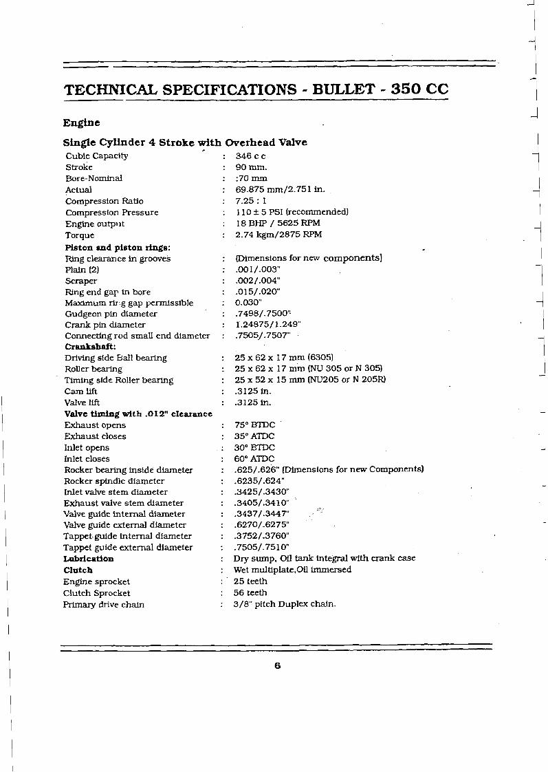
TECHNICAL SPECIFICATIONS - BULLET - 350 CC
Engine
Single Cylinder 4 Stroke with Overhead Valve Cubic Capacity : 346cc Stroke : 9Omrn. Bore-Nominal : :70rnm Actual : 69.875 mm/2.751 in. Compression Ratio : 7.25 : 1 compression Pressure : 110 + 5 PSI (recommended) Engine outpl l t : 18 BHP / 5625 RPM Torque : 2.74kgm/2875RPM Piston and piston rfngs: Ring dearan ce in grooves : Dimensions for new components] Plaln (2) : .001/.003" Scraper : .002/.004" Ring end gap in bore : .015/.020 Maximum rir-g gap permissible : 0.030" Gudgeon pin diameter : .7498/.7500'! Crank pln diameter : 1.24875/ 1.249" Connecthg rod small end diameter : .7505/.7507" crankshaft: Driving side Ball bearLng : 25 X 62 X 17 mm (63051 Roller bearing : 2 5 x 6 2 ~ 17 mm (NU 305 orN 305) Timing side Roller bearing : 2 5 x 5 2 ~ 15mm(NU205orN205R) CamW : .3125 in. Valve lift : .3125in. Valve tizuing with -012" clearance Exhaust opens : 75" BTL)C Exhaust closes : 35"ATDC Inlet opens : 30" BTDC Inlet closes : 60" ATDC Rocker bearing inside diameter : .625/.626" (J3irnensions for new Components] Rocker spindle diameter : .6235/.624" Inlet valve stem diameter : .3425/.3430 Exhaust valve stem diameter : .3405/.3410 Vdve guide internd diameter : .3437/.3447' Valve guide external diameter : .6270/.6275 Tappet.guide internal diameter : .3752/.3760n Tappet guide external diameter : .7505/.7510n ~ r i c a t i o n : Dry sump, OU: tank integral with crank case Clutch : Wet multiplate,OiI immersed Engine sprocket : 25 teeth Clutch Sprocket : 56 teeth Primary drive chain : 3/8" pitch Duplex chain.

Gear Box: Overall gear ratios Mainshaft ball bearings
Final drive sprocket Rear drive chain Brake dnun sprocket Carburettor Main jet Pilot jet Contact Breaker [Coil igdtion): Points gap Timhg before T.D.C. Spark plug
Spark plug gap Condenser (Capacitor) Suspension: Front Stroke Rear Wheel Rim Type w e Size Wheel Bearings : F o n t &Rear) . Brakes Front Rear Fuel tank Full Tank Capacity Reserve Capacity Oil Capacity h Grade: Oil Tank Fork Clutch Gear box
Dimensions: Weight Dry) Pay load (Max) Ground clearance Overall length Overall width Saddle Height Wheel base Electxicals: System
5.32, 7.26, 9.80, & 14.80 Small - 6303 Large - 6206 16 teeth 5/8" pitch chain 38 teeth M i k d - W - 2 4 90 25
: 0.14/0.16" (0.35 to 0.4 mm) : 1/32" (0.8 mm) : 14 mm. diameter B7HS (NGKI or equivalent : 0.46 to 0.50 mm : 0.18 to 0.25 M.F.D.
Telescopic, hydraulic damping 155 mm Pivoted fork with shock absorbers WM 2- 19 3.25 X 19 Front) 3.50 X 19 (Rear) 17 X 40 X 12 mm (6203) or 6203 ZZ Mechanical, internally expanding shoe type 178 mm X 38 mm Twln Leading shoes 153 mm X 25 mm Single Leading Shoe
: 14.5litres : 1.25 litres
: 2.25 litres, SAE 20 W 50 : 200 ml. on each leg. Hydraulic oil or SAE- 10 W 30 : 420 ml. approximately SAE2O W 40 : 700 grams of veedol'00' grease (for topping up use SAE-20 W 501
: 172Kg. : 14cm. (140mm) : 212cm(2120mm) : 75 cm (750 mm) : 85 cm. (850 mm) : 137 cm (1370 mm)

TECHNICAL SPECIFICATIONS - BULLET - 500 CC
8ingle Cylinder 4 8 t r ~ k e with werhead Valve Cubic Capaclty : 499 CC Stroke : 90mm Bare-Nornlnal : 84mm Actual : 83.96/83.97 mm CornpresstDn Ratlo : 6.5:l Compression Pressure : 1 10 f 5 PSI (Recommended] Engine output : 22 BHP/5400 RPM Torque : 3.5Kgm/3000RPM Piston and piston r lngs : IUng clearance in p x w e s : (Dimensions for new components) matn(2) : .001/.003- *raper : .002/.004" Rtng end gap Ln bore : .015/.020n Maximum rlng gap permissfble : 0.038 Gudgeon pin diameter - . . .7498/.7500" Crank pln dlarneter : 1.24875/1.249" Connecflng rod small end diameter : .7505/.7507 Crankshaft : DrMng side Ball bearLng : 25 X 82 X 17 mm (63051 Roller bearing : 25 X 62 X 17 mm (NU 305 or N 3051 Tlming side Wer bearJng : 2 5 ~ 5 2 ~ 1 5 m m ( N U 2 0 5 o r N 2 0 5 R I Camm : -3125in Valve lift : .3125in. Valve thing dth . O 1 T clearance Exhaust opens : 75" BTM)
Exhaust closes : 35"ATM) Inlet opens : 3O0BTDC Inlet clmes : 6O0ATDc Rocker bearing inside diameh : .625/.626" [Dimensions for new Components] Rocker spindle diameter : .6235/.6240n Inlet valve stem diameter : .3425/.3430m Exhaust valve stem diameter : .3405/.341OR Vahre gulde internal diameter : .3437/.3447' - Valve guide external diameter : .6270/.6275 Bppet guide internal diameter : .3752/.3760" Tappet guide external diameter : .7505/.7510" I~bricatim : Dry sump. Oil tank integral with crank case Clutch : Wet multlplate, Oil lmmeraed Englne sprocket : 25 teeth Clutch : 56 teeth himarydrtvechaln : 3/8" pitch Duplex chatn.

Gear b ~ x : Overall gear ratios : 5.01, 6.83.9.22 & 13.93 Overall gear ratios : Small - 6303
: Large - 6206 Ffnal drive chain : 17 teeth Rear drive chain : 5/BWpitchchaln Carburet tor : Mikcarb-W-28 Malnjet : 110 FUot jet : 25 Contact Breaker (Coil ignition) : Points gap : 0.14/0.16" (0.35 to 0.4 mm) Tfming before T.D.C : 1 /32" (0.8 mm) Spark plug : NGK BR 8 ES or equivalent
spark plug gap : 0.46 to 0.50 mm Condenser (Capacitor) : 0.18 to 0.25 M.F.D S n s p d o n : Front : Telescopic. Hydraulic damping Stroke : 155 mm Rear : Pivoted fork with shack absorbers Wheel Bfm Type : WM2- 19 m e size : 3.25 X 19 Front)
: 3 . 5 0 ~ 19(Rear) Wheel Bearings : Front & Rear) : 17x40x12mm~6203)or6203ZZ Brake : Mechanical. internally expanding shoe type Front : 178 mm X 38 mm Twin leading shoes Rear : 153 mm X 25 mm Single lea- shoe Fuel tank : Full Tank Capacity : 14.5 litres Reserve capacity : 1.25 litres Oil Capacity & grade : Oil tar& : 2.25 litres. SAE-20W50 Fork : 200 ml. on each leg. Hydraulfc Oil or SAE 10W30 Clutch : 420 m]. approximately SAE-20W40 Gear Box : 700 grams of veedollOO' grease (for topping up use SAE 20W50) Mmensione : Weight (Dry) : 168 ~ g . ' Pay load (Maxl : 172 ~ g . - Ground clearance : 14 cm (140 mm) Overall length : 212 cm (2120mml Overall width : 75cm (750mm) Saddle Height : 85 cm (850 mm) Wheel base : 137- (1370mm) Electrlcals : System : 12VDC
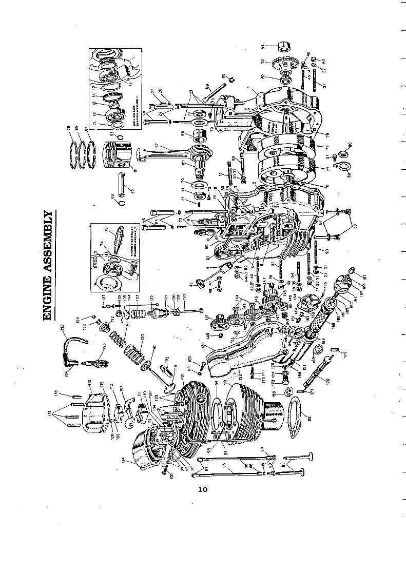

ENGINE PARTS
1. CrankcaseD/S
2. Crankcase T/S
3. Joint washer
28. Crank Case Stud below Distributor
56. Washer, OU Pipe Union
5 7. Washer Oil fllter Cause -- -
29. Washer. below Distributor 58. Oil feed & return filters P
30. Nut, below dLsMbutDr 4. 011 filler car, wllar
~
59. Breather pipe 31. Stud-Front engine plates
P
60. Breather pipe cllp 32. Washer, Front Englne plate
6. Idler p u n mlndle 61. Piston 33. Nut, Ront Engine Plate
62. Gudgeon Ipln 7. Timing shalt mUer bearing 34. Read engine plates
35. Washer. Rear Ensine Plate 8. Tappet guide
9. Cylinder base stud
10. ctrc1l.R (SeeuQrl 36. Nut RearEnginePIate
65. Piston ring (compression) lower taper 37. Stud, Crank Case Rear Joint
38. washer. Crank Case Rsar Joint
66. Piston ring (compmpression) 12. Ball healing top. chrome
39. Nut, Crank Case Rear Joint
40. Stud. Crank Case Rear Jolnt
41. Washer, Crank Case Rscu Jolnt
67. Connectfng rod 14. Distance tube (outer) 68. Connectfng rodmtirtg bush 15. Distance tube (Inner) 69. Crank pln 16. Roller bearing
1 7. Stud, Crank Case Neck
18. Washer. Crank Case Neck Stud
70. Thrust washer 42. Nut. Crank Case Rear Joint
71. Cmnk pln nut
72. Crank pin oU hole grub mew
73. Crankpin nut keeper screw
74. Thrust wzsher
44. Oil Seal Retainer P
19. Nut, Crank Case Neck Stud 45. Nut, OU Seal Retainer -
20. Stud Crank Case Bottom Jolnt
46. Distributor flanae pin
75. Thing shaJt
76. Driving shaft
77. F& wheel T/S
47. Distributorjlange pin wash& 21. Washer. Cmnk Case Bottom
Joint
22. Nut. Crank Case Bottom Joint
- c?
50. Washer. Tappet Cover Stud 79. Lock rim - --
51. Tappet Cover 24. Washer. Head and Cylinder Stud
80. TIS shaft nut 52. Washer (Fibre), Tappet
Couer Stud 25. Washer. Head and CylMer Stud 82. Engine sprocket distance
tube 53. Washer (Steel), Tappet
Cowr Stud 26. Nut. Head and CyUnder S W
27. Nut. Head and Cylinder Stud
83, Engfne sprocket 25T 54. Tappet cover nut
84. Alternator distance tube 55. Oil pipe unlon


85. Push rod inlet
86. P u s h rod exhaust
88. Push rod end bottom
89. Push nxi cup lock nut
90. P u s h d c u p
91. Tappet
92. Culinder barrel ioint washer
93. CqIMer barrel
94. Cyllnder headjoint washer
95. Stud. C y l M e r Base '
96. Rocker oil pipe wrnplete
l l 7. Nut (long) Rocker Box 148. Timing pinion 20T
118. Valve 149. Key
11 9. Valve spring ab, bottom 150. ou p-p m r m
120. Valve spring. outer 151. Ollpumpdlscspring
121. V a l w spring. Inner / 52. Sprtng end pad
122. Va lw sprtng ab, top 153. Casket 0 1 1 hrmp Cowr
123. V a l w split wllar 154. OU pump a v e r
124. Valve stern cap 155. OU pump cover screw
125. Spark plug 156. Nut, Oil Clsaner Stud
126. Spark plug cap 15 7. Washer, 011 Cleaner Stud
1 2 7. H.T. Lead 158. Stud; 0[1 Cleaner
128. Decompressor mlue 159. 011 cleaner eiement
97. Rocker Oil Union Bush 129. Washer, Decompressor 160. OU cleaner spring cap Washer WY
161. Felt washer 98. OU union bush 130. Washer. Decompressor
MY 162. T h t =her 99. Washer Oil Plpe banjo
Union 131. Washer (Plain), 163. 011 cleaner spring
101. Cylinder head
102. Valve auLde ~ ~
103. S tud Rocker Box
1 04. S tud Rocker Bearinq
l 05. Washer, Rocker Bearing
1 G6. Nut, Rocker Bearing
Decompressor M y
132. Decompressor M y
133. Spring. Decompressor
134. Spring Cap. Decompressor
135. Cable block
136. Cable block spllt pin
13 7. Decompressor &le assembly
164. Washer, OU Cleaner Cap
165.011 cleaner cap
166. Washer. 011 Ckaner Cap Nut
167. Nut. Oil Cleaner CQD
168. OU pumr, dlsc lfeedl
169. ,011 pump dlsc (return)
170. 011 pump spindle - - - 107. Rocker, M e t 138. Timing wwr 1 71. Plunger Ifeedj 108. Rocker, exhaust 139. Timing wwr jo tn t washer 72. (rekm
109. Rocker beating inlet 140. Distributor pinion nut 173. ou f&plug l 10. Rocker be&g aap, M e t 141. ~ls tr ibutor plni6& 40T 174. Washer 1 1 1. Rocker bearing, exhaust
142. Idler D W ~ 4OT 1 75. Cork oil retainer 112. Rocker bearing cap,
exhaust 143. Idler p W n bush 1 76. Timing m w r screw
113. Gasket 144. I d l e r p W n thrust washer
1 14. Rocker bow, M e t 145. cam wet
115. Rocker bor exfmst 146. Cam. exhaust
1 77. Spring washer. Tlmlng Coveiscrew.
1 16. Nut (short) Rocker Box 1 4 7. Cam bush

ENGINE
Decarbonising:
After a few thousands of Kms. of run the carbon. build up in the engine will cause general falling off in power, accompanied by increased fuel consumption and starting trouble. Decarbonising will normally be n e c e s s q approximately every 8,000 Kms. and this can be carried out without removing the engine fiom the frame. The mileage between decarbonising will vary from machine to machine depending upon the type of usage. A machine used for frequent short journeys will need more attention than one which is used for fast long distance touring.
1. Removal of the petrol tank
Close the petrol tap. Disconnect the fuel hose from petrol tap end.
Remove the two studs which holds the petrol tank to the frame and pull the tank upwards.
2. Removal of the Cylinder head Remove the engine steady eye bolt. Disconnect the high tension lead from the spark plug. Remove rocker oil pipe. Remove the exhaust pipe and silencer. Remove the air filter by undoing the bolts on the sides of the air filte; body. Push the carburettor back clear of the studs after removing the fudng nuts. Remove the rocker box covers. Remove the decompressor cable from the lever end of the handle bar (LH side)
Crank the engine until both valves are closed. (Keep in Compression stroke).
Remove the rocker
CYLINDER HEAD arms and bearings completely after removing the four 3 / 1 6". nuts on each.
Lift out the push rods both inlet & exhaust.
Remove the six cylinder head nuts & washers.
Lift the cylinder head off the barrel, tapping it genly beneath the exhaust and inlet ports with a wooden mallet. Do Not tap the fins.

3. Removal of Cylinder and Piston
Slacken the two clamp nuts on top of the crank-case neck
Remove the 1/4" nut above the tappet chest and lift the barrel
Remove the circlip retaining the gudgeon pin on the timing side of piston taking care not to drop the circlip into the crank m e .
Extract the gudgeon pin using special Tool PED 20 15 (with adaptor if necessary), so that the pin and the piston may be r e p l a d the same way round, i.e., split skirt toathe front.
REhfOVAL Of PISTON -
During this operation put a piece of clean m.g in the top of the crankcase to prevent foreign matter getting in. Finally cover the c r a n k m with a clean cloth to prevent ingress of dust and dir t
4. Removal of Valves VALVE SPRING COMPRESSOR To remove the valves from the cylinder head,
first lift off the end caps from the valve stems. If this has stuck, it can be removed by a screw driver. Using compressing tool PED 20 18 ST a m p r e s s the valve springs and remove the split collars from the valve tip. Slacken back the ampressing tools and release the springs.
Withdraw the valve and place its springs, top spring collar, bottom collar, the end cap and split conical collars together in order that they may be reassembled with the valve from which they were removed.
If the valve will not slide easily through the valve guide. remove any sIight burrs on the end of the valve stem with a carborundum stone or by using a f i e Jeweller's file to remove any sharp edge or burr. If the burrs are not removed and Ihe valve is forced out. the valve guide may be damaged.

5. Decarbonising the Cylinder head - Combustion Chamber
6. Hston and Rings
If the piston rings are in good condition they can be put back, taking care to fit them in their original grooves and the same way up. If the fitlgs show bmwn or black patches or if their gaps, are more than specified senice limits (Page 79), when in position in the barrel, new rings should be fitted. The correct gap for new rings is given in the technical specifications (pages
6 13 8 ) for 350 and 500cc. The gap should be measured in the least wdrn part of the cylinder which will be found a t the top or bottom of the bore.
Only For 350cc:
The original size of the cylinder bore is 2.751" (69,875rnm). If the wear at any point in the bore exceeds .008" the cylinder should be rebored to .020" and an oversize piston fitted. (It should be rebored to .040" &er a further .008"Wear). Piston sizes available are . 0 2 0 and .040" oversize.
The original side clearance between the piston rings CRANKSHAFT BIG END BEARING
and grooves is .003". If the grooves show a wear of .005" the piston should be replaced.
7. Big end bearing inspection
Examine the condition of ttle big end while the piston is removed. About .010" - .026" end float is permissible and it will be possible to rock the connecting rod slightly. The big end has a floating bush with an original clearance of approximately .003" However, if a DEFINITE up and down play can be felt, engine should be stripped further to have the big end renewed.

8. Valves, Valve Guides and springs a
6 - STEM CAP
s p u r COLLAR
sPNNC
INNER SPRING
OUTER SPRING F @B- s p R I N G ~ ~
VALVE GUIDE
Wear on the vahe stems can be seen on examination and ifa de£inite step has formed, the valves should be renewed. Before replacing the valves, they must be ground on to their seats, if good faces are not formed with a reasonable amount of grinding. the seats must be cut with a cutter (included angle 90') and the valve refaced in a universal grinder. Do not attempt to form good seats by an excessive amount of grinding. This will cause pocketing and restrict the flow of gases. If a pocket has already been formed this must be removed by cuttlng with a v&e seat cutter larger in diameter than the vahre head.
Test the valve guides for wear by trying the fit of a new valve in them. Both valves s h u l d be quite free. but the exhaust valve has more clearance (.002") than Met valve.
To remove the valve guides fYom the head. two special tools are required which can be easily made. The h t is a piece of tube with an internal bore of not less than 7/8" . The second is a mandrel about 4" long made fYom 9/ 16" diameter bar with the end turned down to 1/3" ~ S S O R ~ Y
diameter for a VALVE L! length Support of 1/2". the CABLE ADJ USTINC SCREW
cylinder head on the tube which fits over the collar of the valve guide. Using the mandrel. force the guide out of the head with a hand press or by using a hammer.
To fit a new guide, support the head at the correct angle and use a hand press and the same mandrel. If a hand press is not available, the guide can be replaced using a hammer and a mandrel, to prevent damage to the guide.
Check the length of the valve springs which are oiighml& 2.020 and 2.095 for the inner and outer springs respectively. If these have reached the specified sewice limits, they should be renewed.
9. Decompressor
If the decompressor holds compression and operates freely. there is no need to interfere with it except to remove the carbon fYom the head of the vdve. If the valve is leaking. it will be necessary to regrind it on its seat This can be done without completely dismantling it. Having disconnected the control cable from the handle bar. unscrew the decompressor from the cylinder head. Compress the spring and remove the spring cap. Unscrew the adjusting screw and locknut f?om the cable block and pull the cable sideways out of the block. Push the spring.

upwards and pull the cable nipple out of the body, It will now be possible to remove the cable and nipple through the spring, leaving the decompressor body and spring detached from the control cable.
The spring and the cap should now be replaced. The valve may be ground in by applying a thin coating of grinding paste on the seat of the valve and twisting it to and fro by means of the cable block a t its upper end and occasionally lifting the valve ffom its seat. Do not rotate the valve through a complete revolution before lifting, as this will g;oove the seat. M e r grinding, wash the whole assembly thoroughly in petrol, opening and shutting the valve while doing so. Make sure that all traces of grinding paste have been removed. If the paste should get into the cylinder serious damage would be caused.
If the valve shows a tendency to stick-up in the body but otherwise is satisfactory, this can be cured by washing in petrol, though in this case it will not be necessary to disconnect the control cable.
If the decompressor valve is badly burnt or bent it must be replaced.
10. Re-assembly after Decarbonising Before building up the engine, see that all parts are scrupulously clean and place them on
a clean tray, work bench or over a clean sheet of paper. While re-assembling it is advisable to fit a new gasket between the cylinder barrel and the crankcase.
Smear clean oil over the piston and space the ring gaps. The second ring is a taper ring and is marked TOP on the upper surface. WARNING: This mark should be on top when fitted. Reversing the ring will result in pumping
of oil into the cylinder and consequent smoking. Place the piston over the connecting rod small end ensuring the split skirt is facing the
front and-insert the gudgeon pin. Secure the gudgeon pin with the circlips. Oil the cylinder bore and gently push barrel over the piston while keeping the rings compressed in their grooves and seat it gently on the barrel gasket. Refit the 1/4" nut above the timing chest.
When fitting the head again, apply jointing compound sparingly on both sides of the gasket, - Replace the six nuts and tighten them progressively and diagonally from one side to the other to prevent distortion. WARNING: Excess compound may block oilways. Place the push rods with the adjustable parts downwards. The shorter pushrod is the Inlet. -
Ensure valve stem caps are fixed on the valve stems. Position the rockers and bearings. making sure that the oil feed holes are a t the bottom and that the caps and bases are in line when tightened down. Adjust the push rods after ensuring piston is in TDC' on compression stroke. - The silencer could be cleaned of carbon using a hot caustic soda solution, if necessary. NOTE: The cylinder head and base nuts should be checked agaln for tightness, after the
engine has been run long enough to get it thoroughly warm. Tighten the clamp nuts on crankcase finally. For torque tightening or cy. head nuts please refer torque chart on PageNo. 100
CYLINDER HEAD 350CC CYLINDER HEAD SW CC

SERVICE OPERATION - WITH ENGINE ON FRAME
1. Removal of the Tixning cover &ct,,'F
First place a tray under the engine to hold the oil which will escape when the cover is removed.
Remove the exhaust pipe and silencer. Remove ten screws from the timing cover, taking care not to lose the S washers, one for each screw.
<
NOTE: When the timing cover it is Important that the engine is gently - cranked. This will preven? damage 07 the pumpworm or the pump spindle.
ersd H / ~ . 4 4 w ~ r 4 en mallet Draw off the timing cover, h$$& it lightly if necessary with a woo8
dlafr f" , While refitting the timing cover ensure that theJoint wasH%r is correctly located over the ofl
holes. using a little grease (not compound) to hold it in position. xw c y +
Ensure that the cork p ug is in position in the hole in the pump worm. If the plug is damaged it should be renewed to ensure oil flow to the big end bearing.
NOTE: The Alter chamber should be !Wed with clean oil before the timing cover is refitted.
Ensure proper functioning of oil pump by checking oil flow at rocker ripe union whenit&e engine is running at slow speed. Slacken the oil pipe banjo union to see the oil-flow and clamp it again properly. Wipe the oil that has oozed o u t
- OIL FILTER ELEMENT IN nMlNG COVER
OIL FILTER ELEMENT

2. CIeaning/Replacement of Oil Filter Element - Oil Feed and Return Filters I
The oiI filter is located in the timing cover immediately below the oil pumps. The felt element should be taken out and washed in petrol after the first 800 Kms. and subsequently, every 4.000 Krns. Fit a new element every 8,000 Kms.
The filter element can be removed by unscrewing the nut holding the end cap in position. When re-assembling the filter take care that no grit or other foreign matter is stlcldng to it. After replacing the Alter element it is essential to nm the engine at idling for about five minutes to ensure that oil reaches the big end. If the tfming cover has been removed, fill the filter chamber with clean oil before replacing the cover.
The feed and return filters are fked on the drain plugs in oil sump and crank case. These can be cleaned by rinsing in a solvent and during reassembly ensure the filters are not twisted.
VALVE TIMING MARKS
FELT WASHER -4 I METAL WASHER
SPRING
3. Overhauling of Oil feed and return Pumps -Remove the timing cover.
-Remove the end covers from both pumps.
-Remove the pump discs and plungers.
-Remove the pump spindle which can be pulled out only from the front or return pump end.
--Check the fit of the plungers in the pump discs which should be &ding fit and should be able to be moved in and out by hand. 011 FEED d RETURN PUMPS ASSK
W"" PLUNGER FEED

When matching a plunger in the pump disc, if it is found to be too tight a fit, carefully lap the plunger in the pump dfsc. Using metal polish until it is just free.
If the pump disc is not seating properly in the timing cover or if a new pump disc is fitted, it should be ensured that the pump disc matches properly and has a perfect seating in the timing cover.
Lap the discs in the timing cover with fine metal lapping paste or liquid metal polish using special tools PED 2034 ST for feed pump disc and PED 2035 ST for return pump disc, until a fme, grey surface is obtained on the pump disc face.
NOTE: Replacement pump discs have a lip left at the opposite side of the lapped face. The purpose of this is to hold the disc. central in the housing during lapping-in. it should be filed off before the pump is finally assembled. Care should be taken not to damage the lapped face.
Wash all components and passages. thoroughly with petrol, after lapping, to remove all traces of grinding paste. Check the pump disc springs for fatigue by assembling in the timing cover and placing the pump covers in position. The latter should be held 1_/8"off the timing cover if the springs are correct. The pump spindle should be renewed if excessive wear has taken place on the teeth.
Reassemble the oil pumps, replacing the cover gaskets. Before fitting each cover £ill the pump chamber with clean oil. Having assembled the pumps, lay the timing cover flat and the oil ports using an oil can. Turn the pump spindle with a screwdriver in a clockwise direction and it can then be checked whether the pumps are operating correctly. Before replacing the timing cover on the engine. £ill the filter chamber with clean oil and fit the filter element.
NOTE: With the engine running, the oil feed to the big end can be checked by partially unscrewing the feed plug in the timing cover between the oil pumps and the oil return can be checked by slackening the rocker pipe banjo bolt on the cylinder head and obsen?ng the oil flow.
4. Removal of Pump Worm and Timing Pinion
Unscrew the pump worm using the hexagon head behind the worm, with special tool PED 2006. Withdraw the timing pinion using special tool PED 20 13.
CAUTION: The worm nut has a left hand thread. When turned clock wise the worm nut can be loosened and when turned anticlockwise the worn nut gets tightened.
NOTE: When refitting the timing cover ensure that the cork is in position in the worn nut and is undamaged. This forms a seal between the oil feed plug and the oil passage in the crank shaft, timing side. If necessary this should be replaced and care should be taken to have it fitted correctly.
CAUTION: If this cork is not fitted or damaged. thkoil feed to the big end bearing through the timing shaft will tend to escape past this point causing starvation of lubrication to the big end bearing leading to premature failure of the big end floating bush, engine bearings and other parts.

5. Removal of Contact breaker housing.
Loosen the distributor pinion nut and pull out the distributor pinion off the distributor shaft after removing the idler pinions.
Loosen and remove the three screws which secure the spigotted contact breaker housing and seperate from crankcase. Remove the contact breaker cover. Remove the base plate after removing the two hex bolts securing it.
Pull out the contact breaker shaft from the housing. The two sintered bushes provided in S-
the housing would have to be replaced only if excessive radial play is noticed on the distributor shaft.
Reassembly is just the reverse process of dismantling but take care to replace the washer between the contact breaker housing and the crank case. DE7AlL OF FELT OIL CLEANER
6. Valve Timing
The cams are integral with the cam pinions. They have internal sintered iron bushes running on fixed spindles in the timing chest.
The cams and the timing pinion are provided with timing marks to set proper valve timing. The procedure is detailed below.
\
Bring the piston to TDC Match the exhaust cam (provided with two sets of punch marks) with the timing pinion so that the two punch marks coincide on both. Match the inlet cam to the exhaust cam so that the single punch mark coincide on both. Push the cams home towards the crankcase.
MARK O N INLET CAM B: MARK ON EXHAUST CAM C: MARK O N TIMING PINION
7. Tappet Adjustment - Cold
It is very essential to ensure that the valves are closed fully during the closing period of the cam. The tappet clearance should be adjusted properly to achieve this and to cater to certain
r n r u u s n ~ e r ~ ~ ~ ~ s amount of thermal expansion of the working components. We recommend 'NIL' clearance for the tappets to be set a t cold. Provision for adjustment is given at the bottom end of the push rod which sits overfie tappet. Access to this is by removing -&, I the tappet cover.
Proceed as follows for adjustments. Bring the \ piston to TDC at the end of compression stroke,
so that both the valves are at the closed position. This may be ensured by seeing the valve timing
h marks, if the timing cover is open or through ammeter needle in its centre position, when ignltion is switched on.
Check the push rods. They must rotate thumb free without any up and down play.
In case the push rods do not rotate freely or if up and down play is noticed, the push rods need to be adjusted.
Loosen the lock nut in the adjuster, by holding the top nut. Thread in or out, the bottam adjuster, till the conect push rod freeness is achieved. Retighten the lock nut after adjustments are complete.
CAUTION: If the cylinder head has been disturbed for any attention, ensure proper fitment of valve stem caps and rocker bearings before proceeding to tappet adjustment.
NOTE: Owing to the initial bedding down of the wearing surfaces, the tappets on new engines may require adjustment after the first few hundred kilometres of run.
8. The Clutch - 350cc and 5 0 0 cc The 350cc clutch has five driven plates and four driving plates, including the fiiction disc
on the sprocket. The 500cc clutch is similar to that of 350cc. except that there are six driven plates and five
driving plates. Also the lugs on the clutch sprocket and the splines on clutch centre are longer.
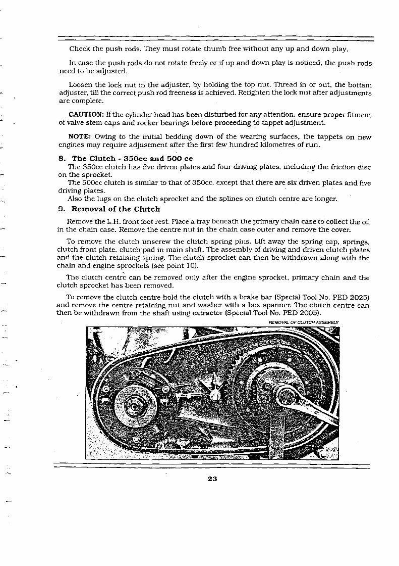
9. Removal of the Clutch
Remove the L.H. front foot rest Place a tray beneath the primary chain case to collect the oil in the chain case. Remove the centre nut in the chain case outer and remove the cover.
To remove the clutch unscrew the clutch spring pins. Lift away the spring cap, sprlngs, clutch front plate, clutch pad in main shaft. The assembly of driving and driven clutch plates and the clutch retaining spring. The clutch sprocket can then be withdrawn along with the chain and engine sprockets (see point 10).
The clutch centrg can be removed only after the engine sprocket, primary chain and the clutch sprocket has been removed.
To remove the clutch centre hold the clutch with a brake bar (Special Tool No. PED 2025) and remove the centre retaining nut and washer with a box spanner. The clutch centre can then be withdrawn from the shaft using extractor (Special Tool No. PED 2005).
REMOVAL OF CLUTCH ASSEMBLY

1. Clutch centre and back plate oqsernbly 2. Cllrtch& 3. Clutch sprocket drum (NISI 3. Clulch sprocket friction disc 3. C l ~ l f c h s ~ r o c k e t frfctton dlsc rfuet 6 6 7. Clutch svrocket ball coae rfoets IN/S1 8. Clutch sorocket balL5 13/16" dial (N/SL 9. Clutch retatnlna spring 10. Clcrtch tntermedlote wlo re ldtshedl U . Clutch plate /insert t&
12. CIutch intermediate plaWfZaU 13. Cltltch b d e d plate ossprnbly - - 17, Clrrtch s ~ r i n a screw 38. Clutch p& J 9. Clutch rod 20. Washer matn sha f t f s ~ m 21. Nut matn short INlrlocl
CLUTCH ASSEMBLY - SW CC
-
ket 56 T & d r w P - - rivet
8 2 SW r o c k e t baILs dd[al fN/SL v
rite- -

10. Removal of Engine and Clutch sprockets
Remove the alternator stator by undoing three nuts. The primary chafn is endless hence it is necessary to remove both the engine and clutch sprockets simultaneously. Remove the central hexagon nut securing the alternator rotor, which can then be drawn off, taking care not to lose the key. The engine sprocket is mounted on splines and can be removed along with the clutch sprocket using extractor PED 2004 ST
1 1. Removal of Final Drive Sprocket .-.
Remove the clut h as described above. Remove the primary chain tensioner. Remove the Y primary chaincase m e r by removing three nuts. Remove the folding of the tab washer which is provjded for locking the final drive sprocket nut. Hold the sprocket and remove the nut (right - hand thread). The sprocket can then be withdrawn.
12. Re-assembly of the Clutch Plates
When re-assembling the clutch plates the following order must be observed.-The clutch pad must be fitted into the main drive shaft, plain dished plate (dish projecting out wards].
Friction plate with inserts. plain flat plate. friction plate bonded. ;lain dished plate (dish projecting inwards). friction plate bonded, clutch front plate 3 springs on the clutch centre lugs. CLUTCH ASSEMBLY
In the case of 500cc one more plain flat plate and one friction plate will also have to be fixed aftkr the plate with inserts has been assembled.
The other three springs are located by means of bosses on the clutch cap. Tighten the spring pins as far as they will go. If the clutch lifts unevenly, it is probable that one of the springs has taken a set. in which case new spring should be fitted.
The friction plate with inserts should be renewed if badly worn or when the inserts have become loose in their plate. The bonded friction plates require renewal when worn or charred. (A light change to a blackish colour should not be mistaken as shamed). Excessive or premature wear
of the plates is due to either running the vehicle at h d clutch application or depriving the clutch plates of oil, with insufficient or no ofl in the clutch chain case.
13. Primary Chain Adjustment Access to the primary chain adjuster is gained by removing the primary chain cover which
is held in position by a single nut. Before removing the nut, place a bay under the engine to collect the oil from the chaincase.
Beneath the bottom run of the chain is a curved slipper chain tensioner pad on which the chain rests. This can be raised or lowered by turning the adjusting screw below the chain tensioner pad after having first slackened the locknut.

PRIMARY CHAIN ADJUSWENT The chain should be adjusted. so that there is 1 /4" up and down movement at the centre of the top run of the chain. Remember to check the chain tension at 3 or 4 places and then adjust accordingly. Ensure that the chain tensioner pad moves freely and the lock nut of the adjuster is retightened after carrying out the adjustment. The chain is to be renewed if its length has increased by 3/4" than the length of a new chain.
After replacing the chain cover. remember to replenish the chaincase with oil [SAE 20) up to the leve1,plug in outer chain case[approx - Qty.. - 430 to 450
14. Adjustment of the Clutch control
It is essential that there should be about 3 to 4mm free movement in the clutch cable. to ensure that all the spring pressure is exerted on the plates.
There are two ~ o i n t s of adiustment on the clutch cable. The first is the midway adjuster at A
CillTCH ADJUSWEhT ON GEAR BOX the middle of the cable just above the chain case. The adjustment is made by screwing the adjuster screw in or out of the adjuster body. Tighten the locknut on the screwed collar after adjustment has been made.
The other point is a t the handle bar end. Loosen the lock nut and thread in the adjuster to increase play and vice versa to reduce play. Tighten lock nut after carrying out adjustment. Homver if the adjusters have reached their maximum position then the adjustment can be carried out in the gear box outer cover. Before proceeding on the adjustment, turn in both cable adjusters to their fully closed position [fully in position).
To make the adjustment, remove the inspection cover, slacken the locknut and turn the central screw in, to get the desired free play on the clutch lever at the handle bar end. Tighten - the locknut after adjustment has been made.

Owing to initial bedding down of the clutch plate inserts. the clutch control may require adjustment after the first few hundred Krns with a new machine. This point should therefore be examined soon after delivery and adjustment made if necessary. Initially, excessive play fn the cable can be taken up through midway adjuster and the adjuster a t the handle bar end.
NOTE: The clutch adjuster ball and clutch rod may require cleaning and greasing around 6000 rniles/10000Krns of run. To do this, loosen and carefully remove the clutch adjuster from its position, taking care not to drop it into the gear box outer cover.
Start the engine and tilt the motorcycle towards the gear box side. so that the clutch rod can be removed. Wash thoroughly. the clutch rod and adjuster and look for chipped or worn clutch rod ends and free rotation of the clutch adjuster ball.
Smear multipurpose grease on the clutch rod and reassemble into the mainshaft. Smear grease on the clutch adjuster ball and carefully reassemble in its location. Adjust the adjuster to ensure free play is maintained on handle bar end and tighten lock nut.
15. Ntting the Alternator
The dternator consists of two parts. the stator and the rotor. The stator is mounted on to the primary chaincase inner by three studs and nuts.
The rotor, which contains the permanent magnet, is mounted on the end of the drive shaft and is located by a key and secured by a special nut and spring washer. The designed radiai air gap between the rotor and the poles of the stator is 0.25mm ( 0.010") and care must be taken when refitting to see that it is not less than O.15mm (O.OOG"] a t any point.
SINGLE PHASE ALTERNATOR
he stam - a f~xed ring wrth c4ib
carrying powec to the sry via the rectlfler