RESONANT FREQUENCY CHARACTERIZATION OF A NOVEL MEMS · 2004-06-17 · RESONANT FREQUENCY...
103
RESONANT FREQUENCY CHARACTERIZATION OF A NOVEL MEMS BASED MEMBRANE ENGINE By ROBERT MICHAEL GIFFORD, JR A thesis submitted in partial fulfillment of the requirements for the degree of MASTER OF SCIENCE IN MECHANICAL ENGINEERING WASHINGTON STATE UNIVERSITY School of Mechanical and Materials Engineering August 2004
Transcript of RESONANT FREQUENCY CHARACTERIZATION OF A NOVEL MEMS · 2004-06-17 · RESONANT FREQUENCY...

RESONANT FREQUENCY CHARACTERIZATION OF A NOVEL MEMS
BASED MEMBRANE ENGINE
By
ROBERT MICHAEL GIFFORD, JR
A thesis submitted in partial fulfillment of the requirements for the degree of
MASTER OF SCIENCE IN MECHANICAL ENGINEERING
WASHINGTON STATE UNIVERSITY School of Mechanical and Materials Engineering
August 2004

ii
To the Faculty of Washington State University:
The members of the Committee appointed to examine the thesis of ROBERT
MICHAEL GIFFORD, JR find it satisfactory and recommend that it be accepted.
________________________ Chair
________________________
________________________

iii
ACKNOWLEDGEMENT
I have been extremely privileged to work so closely with each of my committee
members. I am thankful for the support that each of them has provided. I am especially
grateful for the advice and guidance provided by Dr. Cill Richards as my advisor. She
has never ceased to make herself available to provide the direction and expertise
necessary for me to complete my research. Also, Dr. Bob Richards and Dr. Dave Bahr
have been a continuous source of guidance in relation to the engine operation,
experimentation, and fabrication.
I would also like to thank the entire P3 engine group, both past and present. Each
team member’s contributions have been vital to the success of this research. A few
people deserve special mention. I am thankful for the patience and knowledge of Scott
Whalen and Mike Thompson in teaching me to assemble and operate engines, as well as
countless conversations about engine concepts. Kirsten McNeil has been a huge help in
experiments, and I wish her the best in continuing studies of engine resonant frequency.
Jamie Raupp and Jeong-hyun Cho have been a big help in discussions involving the laser
vibrometer.

iv
Dedication
To Amanda Kristyne.

v
RESONANT FREQUENCY CHARACTERIZATION OF A NOVEL MEMS
BASED MEMBRANE ENGINE
Abstract
by Robert Michael Gifford, Jr., M.S. Washington State University
August 2004
Chair: Cecilia Richards
This thesis provides information regarding the characterization and control of the
resonant frequency of the Washington State University P3 Micro Engine. It is essential
to establish means to measure and control engine resonant frequency, since resonant
operation is vital to the P3 engine operation.
In order to measure the resonant frequency of the engine, a forced-vibration
method and a free-vibration method were developed. Using the forced-vibration method,
an engine assembled with a 3 mm generator, 75 µm cavity depth, and a 500 mm bubble
diameter resulted in a resonant frequency of 10,100 Hz. The same engine was also tested
using the free vibration method where a beating frequency was observed in the “after
ringing” response. A Fourier transform of the response yielded a resonant mode
matching the forced vibration experiment. In order to eliminate the beating frequency an
alternate membrane was used. Using the free-vibration method, an engine assembled
with a 4 mm silicon membrane, 75 µm cavity depth, and a 1170 um bubble diameter
resulted in a resonant frequency of 2037 Hz with an experimental repeatability of +/-
8.6%.

vi
A parametric study was conducted to determine the effects of membrane size,
bubble diameter, and cavity thickness on resonant frequency. Results showed that
membrane size had a very large effect on resonant frequency. Engines assembled with
the same cavity depth but differing silicon membrane side lengths of 3 mm, 4 mm, 6 mm,
and 8 mm had average resonant frequencies of 2550 Hz, 1615 Hz, 742 Hz, and 416 Hz,
respectively. Bubble diameter had very little effect on resonant frequency, providing
only a +/- 8.2% change for bubble diameters ranging from 400 µm to 1500 µm. Three
engine cavity depths were tested: 75 µm, 150 µm, and 225 µm for engines assembled
with 4 mm silicon membranes and varying bubble diameter. An increase in resonant
frequency was seen as the cavity depth was increased. The mean resonant frequencies
with 95% confidence for the 75 µm, 150 µm, and 225 µm cavity depths were 1206 ± 206
Hz, 1615 ± 154 Hz, and 2081 ± 291 Hz, respectively. Therefore, membrane size and
cavity depth have very good potential to control system resonant frequency.
Finally, a model was developed to serve as a design tool for controlling engine
resonant frequency based on system parameters. The model operates under the principles
of an added virtual mass factor, relating the resonant frequency of the engine to the
theoretical resonant frequency of the upper membrane of the engine in a vacuum. The
model was shown to fit the experimental data well. The model was further extrapolated
to provide the necessary engine dimensions required to achieve a resonant frequency of
500 Hz.

vii
TABLE OF CONTENTS
Page
ACKNOWLEDGEMENTS………………………………………………………………iii
ABSTRACT……………………………………………………………………………….v
LIST OF TABLES………………………………………………………………………...x
LIST OF FIGURES………………………………………………………………………xi
CHAPTER
1. INTRODUCTION...................................................................................................1
1.1 Motivation.........................................................................................................1
1.2 Literature Review..............................................................................................3
1.2.1 Membrane Resonators………..………………………….….….....3
1.2.2 Membrane Effects……………..…………………………………..5
1.2.3 Membrane – Fluid Effects……………………………………….13
1.2.4 Membrane – Fluid – Cavity Effects……….……………………..18
1.3 Research Objectives........................................................................................20
2. FABRICATION AND EQUIPEMENT................................................................22
2.1 Engine Fabrication..........................................................................................22
2.1.1 Membrane Fabrication………..…………………..…….………..23
2.1.2 Generator Fabrication……………………………………………24
2.1.3 Heater Fabrication……………………………………………….26
2.1.4 Engine Assembly………………………………………………...27
2.2 Equipment……...............................................................................................30
2.2.1 Pulse System………..…………………..…….………………….30

viii
2.2.2 Laser Interferometer……………..……………………………….32
2.2.3 Laser Vibrometer………….……………………………………..34
3. MEASURING RESONANT FREQUENCY........................................................37
3.1 Forced vs. Free Vibration...............................................................................37
3.1.1 Forced Vibration Method………..…………………..…….…….37
3.1.2 Free Vibration Method…………………………………………..39
3.1.3 Pursuing an Experimental Method………………………………40
3.2 Forced Vibration Experiment.........................................................................41
3.3 Free Vibration Experiment………………………………………………….43
4. ENGINE PARAMETRIC STUDY...........................................................….........53
4.1 Engine Parameters..........................................................................................53
4.2 Experimental Procedure…………………………………………………….54
4.3 Membrane Geometry…………………………………………………….….56
4.3.1 Membrane Size Experiment………..…………………..……..…56
4.3.2 Membrane Size Results……………………………………….…59
4.4 Bubble Diameter.............................................................................................60
4.4.1 Bubble Size Experiment…………………………………………61
4.4.2 Bubble Size Results……………………………………………...62
4.5 Cavity Depth………………………………………………………………...64
4.5.1 Experimental Methods……………………..…….………………64
4.5.2 Cavity Depth Results…………………………………………….65
5. AVMI FACTOR MODEL.....................................................................................67
5.1 AVMI Method................................................................................................67

ix
5.2 Application to Engine……………………………………………………….69
6. CONCLUSIONS AND RECOMENDATIONS....................................................79
6.1 Measuring Resonant frequency.......................................................................79
6.2 Resonant frequency Parametric Study……………….……………………...80
6.3 AVMI Model………………………………………………………………..81
6.4 Recommendations…………………………………………………………...82
REFFERENCES…………………………………………………………………………84

x
LIST OF TABLES
1.1 Densities of materials commonly used for membranes….……...……………...10 3.1 Theoretical resonant frequencies of membranes in a vacuum………………….45 5.1 AVMI Model equations and variables………………………………………….76

xi
LIST OF FIGURES
2.1 Engine configuration …………………………………………………………….22
2.2 Silicon membrane fabrication……………………………………………………23
2.3 Photolithography mask to define membrane geometry………………………….24
2.4 Generator fabrication process flow………………………………………………25
2.5 Completed 3 mm membrane generator sitting on a dime………………………..25
2.6 Ring heater fabrication process…………………………………………………..26
2.7 Completed ring heater with membrane outlined…………………………………27
2.8 Engine assembly procedure……………………………………………………...29
2.9 Pulse system schematic…………………………………………………………..30
2.10 TTL Circuit Diagram…………………………………………………………….31
2.11 Schematic of interferometer with assembled engine…………………………….33
2.12 Typical interferogram for 4 mm upper membrane assembled in engine………...33
2.13 Image of bubble and ring heater…………………………………………………34
2.14 Principle of operation of vibrometer……………………………………………..35
3.1 Mass-spring-damper system……………………………………………………..37
3.2 Forced vibration mass-spring-damper system…………………………………...38
3.3 Free vibration response to an impact force………………………………………40
3.4 Forced vibration experimental schematic………………………………………..41
3.5 Frequency response of the forced vibration of a 3 mm generator engine………..43
3.6 Schematic of free vibration experimental setup………………………………….46
3.7 Free vibration “after-ringing” of 3 mm generator engine…………..……………47
3.8 Free vibration “after-ringing” of Si membrane engine……..……………………47

xii
3.9 Comparison between forced vibration and free vibration………………………..48
3.10 Velocity response of an 4mm Si membrane engine to heat Pulse……………….50
3.11 Curve-Fit of Free Vibration of Engine…………………………………………...50
3.12 Repeatability of engine resonant frequency measured by free vibration..……….52
4.1 Schematic of engine……………………………………………………………...53
4.2 Generator and Si membrane cross-section……………………………………….54
4.3 Free vibration experiment schematic…………………………………………….55
4.4 Oxide mask for 4 mm silicon membranes……………………………………….57
4.5 Oxide masks for 6 mm and 7 and 8 mm silicon membranes…………………….58
4.6 Relative sizes of silicon membranes……………………………………………..59
4.7 Semiconductor tape gasket dimensions………………………………………….59
4.8 Engine resonant frequency dependency on membrane side length……….……..60
4.9 Bubble diameter parameter………………………………………………………61
4.10 Large, medium, and small bubble assembles in engines………………………...62
4.11 Resonant frequency of 4 mm engine at varying bubble diameters…..…………..63
4.12 Engine cavity depth parameter…………………………………………………...64
4.13 Effect of cavity depth on resonant frequency…………………….……………...66
5.1 Non-dimensional parameter α as a function of bubble diameter………………...70
5.2 Theoretical resonant frequency of silicon membranes versus side length..…...…71
5.3 Experimental resonant frequency as a function of bubble diameter……………..72
5.4 AVMI factor Γ as a function of cavity depth……...……………………………..73
5.5 AVMI Model fit for varying cavity depth ………………………………………74
5.6 AVMI Model fit for resonant frequency of various size engines………………..75

xiii
5.7 AVMI Model for 500 Hz Operation……………………………………………..78

1
CHAPTER 1
INTRODUCTION
1.1 MOTIVATION
Thermopneumatic membrane actuators have become increasingly important as a
means of accomplishing work in various Micro-Electro-Mechanical Systems (MEMS)
devices. Devices have been designed for flow control in valves [1,2] and micro pumps
[3-7]. Thermopneumatic operation has proven to be an effective means for actuation in
MEMS. Benefits of thermopneumatic operation include increased precision and control
by use of resistance heaters, large displacements of actuator components, as well as
relatively simple actuator components, often consisting of only a heat source, pressure
cavity, and membrane or diaphragm. However, the entirety of micro thermopneumatic
actuators are limited to operate at low frequencies due to the rate at which heat can be
added and, more critically, removed from the system. This limits most devices from
operating at resonant frequencies where added benefits can occur. Resonant frequency
can result in lower power consumption, increased displacements, and higher conversion
efficiencies. Even more promising, it may be possible that a thermopneumatic actuator
operating at resonant frequency can actually result in a four-stroke thermodynamic cycle
creating an engine [8] or refrigeration [9] device.
If actuators are to achieve the benefits of operating at resonant conditions, they
must overcome the constraints composed by insufficient heat transfer. In this regard,
resonant frequency can be achieved if the rate of heat transfer is increased to system
resonant frequency or if the systems parameters are changed to lower the system resonant
frequency for operation at adequate heat transfer rates. Ideally, by increasing both the

2
heat transfer rate and controlling the system resonant frequency an optimal operation
frequency can be attained. A vast amount of research has been performed to implement
means for increasing heat transfer including heat pipes [10,11] and thermal switches
[12,13]. However, there is relatively little being done in thermopneumatic actuators to
control resonant frequency by changing system parameters. More commonly, researchers
have settled for sub-resonant frequency operation or have ruled out thermopneumatic
operation as a means of achieving resonant frequency, relying on other means of
actuation, such as, piezoelectric or electrostatic.
A novel MEMS thermodynamic engine is in development by researchers at WSU.
The engine consists of a piezoelectric thin film deposited on a flexible silicon membrane
encapsulating a two-phase liquid vapor mixture. When the fluid is alternately heated and
cooled, changes in cavity pressure result in the strain of the piezoelectric membrane.
Strain induced within the piezoelectric is converted to an electric charge across electrodes
that can be harvested. In this manner, pulsed heat is converted to mechanical work
through the expansion of the membrane, and mechanical work is converted to electrical
work through the piezoelectric phenomena [14]. Heat rejection has been defined as a
limiting parameter to resonant frequency operation [15], however, an effective means of
control remains under development. Therefore, this work shall investigate system
parameters as a means to control resonant frequency operation regardless of the heat
transfer rate. Since the engine is essentially a thermopneumatic actuator, this work will
benefit the field of thermopneumatic actuators as a whole.

3
1.2 LITERATURE REVIEW
1.2.1 Membrane Resonators
The goal of this review is to explore the methods used to achieve specific
operating resonant frequencies for MEMS devices employing membranes. Specifically,
the parameters affecting the resonant frequency of a membrane coupled to a two-phase
fluid-filled cavity, operating as an engine, shall be investigated.
The use of resonating membranes in thermopneumatic actuators in the literature is
to date virtually nonexistent. This is most likely a product of relatively low heat transfer
rates. However, the advantage of thermopneumatic actuation over other methods
currently employed merits the investigation of ways to operate membrane resonating
actuators with pulsed heat. Thermopneumatic operation often requires less power, can
provide greater displacements, and devices often undergo fewer processing steps than the
more common actuation methods. The majority of resonating actuation devices employ
piezoelectric or electrostatic actuation. Although these actuators are well suited for very
high frequency operation, they often require very high voltages in the hundreds to
thousands of volts for minimal membrane displacements, making them unpractical for
many MEMS devices.
The lack of resonating thermopneumatic actuators in the literature requires one to
explore other avenues where resonating membranes are used, in order to design a means
of controlling the resonant frequency of a thermopneumatic engine. Fortunately, devices
incorporating resonating membranes are frequently used in MEMS, including micro
pumps [16-18], Micro Ultrasonic Transducers [19-21], pressure sensors [22,23], and even
a micro cryogenic cooler [9]. In each of these systems, controlling resonant frequency is

4
of utmost importance. Micro pumps operating at resonant frequency have higher flow
rates, increasing possible applications and reducing power requirements. MUTs are able
to detect and transmit signals at specific frequencies, effectively filtering noise from other
frequencies. Accelerometers and pressure sensors measure changes within environments
proportional to fluctuations in their respective natural frequencies. The micro cryogenic
cooler relies on resonant frequency to achieve compression and expansion vital to its
operation [9]. In each case, it is important to be able to control or tune the effective
resonant frequency of the system in order to achieve the desired operation. The
parameters used to tune the natural frequency of each device are the geometry, material
properties, surrounding fluids, and packaging. Altering these parameters changes the
mass, stiffness, and damping properties, all of which define the resonating system.
Designing a resonating system requires knowledge of all factors involved.
In order to fully characterize a resonating system it is beneficial to observe how
the additions of individual parameters influence resonant frequency. As an example, a
membrane micro-pump can be divided into a series of components, with each
components addition affecting the overall system. Bardell et al. showed the advantage of
this when they analyzed the resonant frequency of a resonating micro-pump [24]. First,
they analyzed the contribution of the membrane on resonant frequency frequency. Then
the fluid effects were added to the membrane. Finally, the contribution of the valves and
cavity were coupled to the membrane and fluid. This approach provided a systematic
method to understand the contribution of each component on the resonating system. In
the same way, the membrane engine under consideration in this present research can be
divided into three components, the membrane generator, the working fluid, and the

5
engine cavity, each influencing resonant frequency independently. The following review
will explore resonant systems with only the membrane, the coupled membrane and fluid
system, and finally the coupled membrane, fluid, and cavity.
1.2.2 Membrane Effects
A membrane is defined as a perfectly flexible two-dimensional plane of zero
thickness held in tension by a force so great that deflections cause no change in the
membrane tension [25]. The vibration characteristics, and thus, resonant frequency, are
almost entirely dependent upon geometry and material properties. Membrane geometry
is specified by shape, size, thickness, and cross-section. The material properties
influencing resonant frequency include the density, residual or internal stress, elastic
modulus, and Poisson’s ratio.
In theory the vibration of an ideal membrane is quite simple to model. Textbooks
readily give equations of motion for vibrating membranes of various shapes and sizes.
However, the inherent assumptions to linear vibration rarely hold for real-world
applications. Although it provides a decent guide of what factors will influence
vibration, the assumption of linear membrane vibration fails under a generally accepted
“rule-of-thumb” of deflection amplitudes on the order of the membrane thickness [26].
Recent research has shown that even this estimate is far too liberal and non-linear effects
can be observed at vibration amplitudes smaller than four percent of the membrane
thickness [27].
Many researchers are now developing models to explain non-linear effects in
membranes by viewing them as plates subject to bending and internal stresses. One such

6
study develops a model for the non-linear free vibrations of rectangular plates with a
combination of clamped and simply supported boundary conditions [28]. The clamped
conditions yield higher resonant frequencies than the simply supported boundary
conditions traditionally used for membrane analysis. Also, model results show that
vibration amplitudes on order of the thickness can result in a thirty-five percent increase
in fundamental resonant frequency frequency.
Taking these considerations into account, and the fact that most membrane
actuators running at resonant frequency do so in an effort to achieve maximum
displacements, non-linear effects must be considered. The task of modeling non-linear
membrane vibration has been pursued by many research groups [28,29]. However,
studies coupling non-linear membrane vibration to complete resonating systems are still
fairly scarce in the literature. More often non-linear effects in systems are ignored,
attributed as sources for error, or vibration is limited to the linear regime. Many other
resonant frequency applications, with large amplitude membrane vibration, opt to
experimentally determine vibrating characteristics, as the modeling of such systems is
forbiddingly difficult [30-32].
A review of the literature shows that membrane shape is dictated less by the
specific application and more so by the methods available for fabrication. The most
common membrane shape in devices is the square, or rectangular membrane.
Rectangular membranes are easily fabricated using the anisotropic selectivity of wet
enchants such as KOH, TMAH, or EDP [33]. The typical process flows for creating
rectangular membranes employing either a boron or SixNx etch stop are detailed in [33].
Circular membranes, or virtually any shaped membrane, are created in silicon by reactive

7
ion etching (RIE) or deep reactive ion etching (DRIE). A study by Arik et al. presented
the analysis of square, rectangular, circular, and elliptical membranes fabricated through
RIE [34]. The process flow for creating circular membranes is detailed in [33].
Although RIE and DRIE provide flexibility in membrane shape and the possibility of
etching vertical sidewalls, the initial equipment cost is extremely expensive. Therefore, it
is typically used only when available or for applications where the membrane shape is
critical.
Provided access to the appropriate fabrication equipment is available, specific
shapes may offer advantages for the specific resonant frequency requirements of various
applications. Resonant frequency is influenced by a shape factor or natural frequency
parameter, often given by the symbol λij [35], where i and j specify the mode of vibration.
From the fundamental equations for membrane resonant frequency, it can be shown that
the frequency of the fundamental mode of a rectangle is higher than that of a square with
the same surface area, and the first mode of a circle is roughly ninety-five percent that of
a square [35].
Membrane size is the primary method of controlling resonant frequency in
MEMS applications. This is so evident in literature that it is often the membrane size that
dictates its applications. The smallest membranes used in MEMS are as small as 40 µm
[19]. They, and membranes with side lengths or diameters up to about 1 mm, are
primarily used for the sending and receiving of ultrasonic signals [20]. Larger
membranes are better suited for resonant frequency applications requiring large
deflections such as micropumps [7], droplet ejectors [36], or speakers and microphones
operating in the audible range [32,37].

8
The theories dictating membrane size effects on resonant frequency have long
been known, going back to Lord Rayleigh and his studies of sound. In 1877 Rayleigh
published his works on the theory of sound, where he showed theoretically and
experimentally the relationship between size and shape on membrane natural frequency
[25]. He showed that the natural frequency, or pitch, of a membrane increased as side
length decreased. Likewise, changing the shorter length of a rectangular membrane has a
larger effect on pitch than altering the longer side length.
The resonant frequency of a membrane can also be tailored by changing the
membrane thickness. This effect was observed in a study by Paneva and Gotchev [27].
They tested square silicon membranes with 5.35 mm side lengths. Membrane thickness
was varied by etch stop doping levels and anisotropic etching in KOH, yielding
membranes with 5.9, 7.5, 10.4, and 15 µm thickness. The membranes were then driven
to resonant frequency by an AC-voltage applied to a thin film piezoelectric structure
processed on the membranes. Results showed that the resonant frequency of the first
mode decreased proportional to the negative 0.45 power of the thickness. The resonant
frequency of an ideal membrane decreases proportional to the negative ½ power of the
thickness. The difference is reported as being due to the stiffness of the structure.
Muralt et al. also observed the deviation of resonant frequency behavior from a
pure membrane due to thickness [38]. They used a 2 mm diameter membrane and varied
the silicon thickness from about 2 µm to 23 µm. The membranes were then excited to
resonant frequency using a piezoelectric composite layer processed on the center of the
membranes. Results showed that membranes with a silicon thickness below about 3 µm
displayed a resonant frequency decrease with proportionality near that of a pure

9
membrane, that is, f ∝ (thickness)-1/2. As the Si thickness was increased to about 7um,
the resonant frequency increased proportional to the thickness, exhibiting the behavior of
a clamped disk or plate. The point at which the membrane underwent the transition from
membrane behavior to plate behavior is stated as being dependent on the tension of the
membrane. In this way a membrane with small tension forces requires a thinner
thickness to produce a plate-like response. Although a particular value for tension of the
membrane was not given, this may explain what seems like inconsistencies between this
study and the one by Paneva et al. [27] discussed earlier.
Similar to increasing membrane thickness, many MEMS devices employ the use of
bosses, or proof masses, by selectively leaving a mass of silicon with a much thicker
cross section than that of the surrounding membrane. This method is most common in
devices requiring greater sensitivity to inertial changes, such as accelerometers and
vibration sensors. Thomas developed one such device as vibration sensor for tool
monitoring [39]. The vibration sensor employed a bossed membrane as a seismic mass in
order to increase the sensitivity of the sensor. He found that a membrane with a central
boss operating at the same resonant frequency as a membrane with a uniform cross-
section resulted in an order of magnitude increase in sensitivity measuring much smaller
accelerations.
Another device using a bossed membrane is McEntee and Bowman’s design for a
miniature Sterling cycle cryocooler, which required a membrane with sufficient inertia
while operating at resonant frequency to achieve a thermodynamic cycle necessary for
cooling [9]. Unable to achieve this with a membrane of uniform thickness operating at a
specific frequency, they employed a membrane with a thicker bossed center surrounded

10
by a thin, more flexible membrane. Although the authors have to date failed to present
the operation of a micro cryocooler, they developed a model validating experiments to
create an optimal membrane with the largest kinetic energy developed for a particular
swept volume. This optimum was achieved with a circular boss twenty times thicker
than the surrounding membrane, with a radius 30% that of the entire membrane structure.
One shortcoming of the study was that the authors intentionally restricted the membrane
deflection to the linear regime in order to make the model easier to solve. In doing so,
they eliminated possible compression and expansion benefits to their application that may
have resulted from larger membrane deflections.
In most cases defining the geometry of a membrane directly changes the mass of
the system. The material used to fabricate the membrane also has an effect on the system
mass and natural frequency. The densities of some of the most common materials used
for membranes in MEMS are shown in Table 1.1. Because the majority of membranes
are actually composites including layers to sense and actuate membrane vibration, the
densities of other common materials are included in the table. However, density is not
Material Young’s Modulus (GPa)
Density (g/cm3)
Silicon ~ 190 2.3 SiO2 ~ 70 2.66
Silicon Nitride, Si3N4 ~ 130 3.44 Gold 80 19.4
Platinum 147 21.4
Table 1.1 Young’s Modulus and densities for materials commonly used in membrane structures [33].

11
the only means in which material properties will influence the resonant frequency of a
membrane. The Young’s Modulus, Poisson’s ratio, and the residual stress (related to the
material and processing) will also have a large contribution.
The stiffness of oscillating systems is most often thought of as the spring constant
of the system. The system spring constant is equal to the force required to produce a unit
of linear deflection. Likewise, in an ideal membrane the stiffness is accounted for by the
tension of the membrane per unit length of the edge [35]. As previously mentioned, the
pure membrane includes no bending effects of the structure, as by definition it has no
thickness with which to resist bending. The stiffness of a plate, however, is highly
dependent upon bending moments and therefore depends on both the elastic modulus and
Poisson’s ratio. Muralt et al. showed that a realized MEMS fabricated membrane may
exist somewhere between a pure membrane and a plate, the degree of either dependent
upon the tension in the membrane and its thickness [38]. A membrane with a large
thickness and small in-plane tension will behave more like a plate, however, a membrane
with very large in plane-tension will behave more like a pure membrane.
Degen et al. showed that the dependence of resonant frequency on in-plane
tension could be used to determine the residual stress of membranes used for open stencil
masks and mini-reticles [40]. In their study silicon membranes with a side length of 6
mm and a thickness of 6 µm were evaluated. Membranes were excited by pressure
waves from a speaker placed in close proximity to the membrane. A piezo-resistive
cantilever was placed in contact with the center of each membrane in order to measure
the amplitude response to the sound waves. The maximum amplitude during a frequency
sweep defined the position of the first resonant mode. Once the resonant frequency was

12
known and accommodations were taken for air loading effects, the residual stress was
calculated from:
20
11
2
2
1
Lf
⋅⋅
=ρ
σ 1.1
with: f11: first resonant mode of vibration
σ0: residual stress
ρ : membrane material density
L: membrane side length
Calculated residual stresses from resonant frequency measurements agreed within 0.1
MPa of other methods employed. The results validate the resonant frequency method for
determining residual stress. Likewise, they show how changing the residual stress of
membranes is an effective means of tuning resonant frequency.
As discussed earlier, most membranes used as sensors and actuators are actually
laminates of various layers. These layers also individually contribute to the overall
residual stress of the membrane, as noted by Kennedy et al. [41]. Employing a fairly
common piezoelectric composite structure on a silicon membrane substrate, Kennedy
measured the residual stress contributions from each deposited layer. The layered
structure consisted of a silicon membrane, TiW, Pt, PZT, and Au. The residual stress of
each individual layer was measured using x-ray diffraction. Each layer contributed to the
composite residual stress measured by the bulge test method in which the membrane is
pressurized on one side and deflection measurements are taken. The goal was to reduce
the overall residual stress in the composite. To accomplish their goal they added an
additional tungsten compressive layer, effectively lowering the composite tensile residual

13
stress. In this manner, the resonant frequency of a 3 mm square membrane with a
composite thickness of about 2.8 µm was reduced from 23 kHz without a compressive
layer, to 18 kHz with the addition of a compressive layer.
Most composite membranes are designed for sensing or actuation and therefore
undergo mechanical and electrical couplings that can shift the resonant frequency.
Although this particular topic is beyond the scope of this review to investigate in detail, it
is interesting to note the methods that piezoelectric and electrostatic resonators can
employ to electrically effect resonant frequency. Specifically, a resistive or capacitive
load placed across the electrodes of a piezoelectric transducer can result in a small shift
of the first mode [42]. Similarly, the resonant frequency of electrostatic transducers can
be precisely tuned through the addition of a DC-bias [43].
1.2.3 Membrane – Fluid Effects
The media or fluid surrounding a resonating structure has a dramatic effect on the
system adding mass, damping, and in the case of a compressible fluid, spring forces.
Although these effects have been observed and theoretically explored for more than a
century, a broad range of research groups today continue to explore resonating structures
and fluid interactions. In the area of membranes, research has been limited to structures
either surrounded completely by a homogeneous fluid or having one side exposed to a
homogeneous fluid. However, the area of MEMS thermopneumatic membrane actuators
and engines provides a unique situation in which a two-phase fluid is in contact with the
vibrating structure. In fact, only one study was found that addressed the problem of a
vibrating structure in a two-phase fluid. Billingham attempted to model the effect of a
two-phase fluid in contact with an idealized resonating rod [44]. He found that a two-

14
phase mixture with fluids of similar density, such as oil and water, could be approximated
as a single-phase fluid with a weighted density. However, his single-phase model failed
when he considered a two-phase mixture of fluids with vastly different densities, such as
water and air. Fortunately, homogeneous fluid studies provide a firm foundation upon
which to build for the case of a two-phase fluid and can provide very good qualitative
trends in fluid properties influencing resonant frequency. The primary fluid properties of
interest are viscosity, density and pressure.
Damping, largely due to viscous forces in phase with the velocity of the structure,
has very little impact on resonant frequency for fluids with viscosities less than 0.006
N⋅s/m2 [45]. For reference, at room temperature water has a viscosity of about 0.001
N⋅s/m2 and air has a viscosity of 0.000018 N⋅s/m2 [46]. More practically, the viscosity
serves to dissipate system energy, causing a faster decay in free vibration and reducing
the resonant frequency amplitude at forced vibration. Inaba et al. showed that the
amplitude of the resonant frequency peak within the frequency response of a cantilever
decreased and the half power width broadened with higher viscosity fluids, but the shift
in resonant frequency due to viscosity was negligible [47].
Physically, a shift in resonant frequency in most fluid media is due to added mass
effects, where the inertia of the fluid moving in phase with the displacement of the
vibrating structure acts as an effective added mass to the structure itself. Lamb pioneered
the theories behind this phenomenon in 1921 as a method to answer questions arising
within submarine signaling [48]. Lamb clamped a circular elastic plate within an
aperture of a solid rigid wall. One side of the plate and wall were then placed in contact
with water. His results showed that the natural frequency of the plate with one side in

15
contact with fluid could be related to the natural frequency of the plate in a vacuum by a
multiplied factor proportional to the kinetic energy of the plate and the kinetic energy of
the fluid. The relationship between the kinetic energies of the plate and fluid are still
used extensively by researchers to theoretically determine added mass effects on
resonating structures in fluid.
Since Lamb’s research, the ratio between the kinetic energy of the fluid due to
plate or membrane motion and the kinetic energy of the plate itself has been known as the
added virtual mass incremental factor, or AVMI factor for short [49]. The AVMI method
provides a very powerful analytical approach to approximating the effect of fluid loading
on vibrating structures. Kwak and Kim showed how the AVMI factor could be used to
accurately predict the resonant frequency of a circular plate under various clamping
conditions [49]. They showed that the AVMI factor, β, could be solved simply as:
Γ⋅⋅=P
P
P
f
t
r
ρρ
β 1.2
with: ρf: fluid density
ρP: plate density
ρP: plate radius
t: plate thickness
Γ: non-dimensional AVMI factor accounting for vibration mode and clamping
This same method was later employed by Kwak to solve for the resonant frequencies of
circular membranes in contact with fluid under various clamping conditions [50]. The
AVMI method has been well accepted by many other researches as a method to

16
accurately predict the resonant frequencies of plates and membranes in contact and
submerged in both compressible and non-compressible fluids [35,40,45,51-54].
An exact solution to the fluid-membrane coupling has not been completely
determined. The solution becomes extremely difficult because although the membrane
solution is two-dimensional, the fluid movement is three-dimensional, adding to its
complexity. Structural-fluid interactions as a whole have received a lot of attention to
determine exact solutions, but as structure shapes become more complex, the amount of
available research becomes limited. For example, the vibration of a beam or cantilever in
a fluid has been well explored numerically [55,56,57], but an exact solution to a
membrane in contact with fluid is, to date, unavailable. For cantilevers it is common to
use the Navier-Stokes equations to determine fluid reaction forces [58]. In the area of
plates, the Analytical-Ritz method [59] has been employed, as well as the Finite Element
Method [60].
The largest application area of MEMS membrane-fluid systems operating at
resonant frequency is micro-pump systems. The effect of the fluid-structure interaction
on resonant frequency is commonly determined by observing the effect of operating
frequency on pump flow rate [30]. The operating frequency resulting in the greatest flow
rate defines resonant frequency. When modeling micro-pumps the most common
approach is to determine the added mass to the resonating system by solving equations
for the flow-rate per cycle [17,61,62]. In the same way, system damping is determined
by resistance flow through the inlet and outlet valves. Although the theory of
determining added mass in micro-pumps sounds quite simple, the actual calculations are

17
quite rigorous, as the majority of MEMS pumps developed today use nozzles and
diffusers to direct flow [16,17,24,62] resulting in coupled non-linear equations [62].
Another common use for resonating membranes is in the area of pressure sensors.
An increase in pressure results in an increase in the surrounding fluid density. As noted
earlier, an increase in density adds mass to the system resulting in a decrease in resonant
frequency. However, the influence of pressure alone is quite small. Most research
showing this effect has been performed on cantilevers surrounded by fluid. Inaba and
Han showed the effect of changes in pressure at low pressures between 10 and 100 kPa,
which resulted in a maximum frequency shift of only about 0.2% [63]. In another study
Mertens et al. tested cantilevers over a range of pressures from 0.01 Pa to 1000 kPa, and
observed a maximum frequency shift of just 2.5%, 2.3% of which occurred at pressures
greater than 100kPa [64]. Since the influence of pressure on resonant frequency is quite
small, virtually all resonating membrane pressure sensors rely on a pressure differential
across each side of the membrane, resulting in changes in deflection. In this scenario a
rise in pressure on one side of the membrane results in an increase in resonant frequency
due to membrane stiffening. Defay et al. showed that this effect could be used to
measure pressure with very high precision, with a resolution of 11.5Hz/kPa in the 2 to 10
kPa range [22]. Keeping this in mind, it is very important to control the mean pressure
differential across the membrane, as the impact on resonant frequency can be quite large.
Up to this point, the compressibility of the working fluid has been neglected,
which is common for most systems operating in a fluid infinite in all directions.
However, the packaging of Microsystems allows for sealed cavities in which fluid can act
as a spring. Also, it stands to reason that the cavity dimensions may cause further effects

18
on the resonant frequency due to the properties of the working fluid. Therefore, in the
following section, the effects of a membrane encapsulating a fluid in a cavity with rigid
sidewalls shall be explored.
1.2.4 Membrane – Fluid – Cavity Effects
The first and most obvious effect of a membrane sealing a compressible fluid
within a cavity is the opportunity for the membrane deflection to generate pressure within
the cavity. In this way the membrane-cavity system is analogous to a simple free-piston
and closed cylinder. The piston-cylinder problem is readily available in textbooks and in
its ideal form behaves as a mass-spring system. The mass of the system is equivalent to
the mass of the piston and the compressible fluid is modeled as a one-dimensional spring.
Assuming the system is isentropic, the effective spring constant of the compressible fluid
is then, k = κp0A2/V0, where A is the piston area, p0 is the mean pressure, V0 is the cavity
volume, and κ is the non-dimensional polytropic constant related to the ability of the
volume to transfer heat (for air 1 ≤ κ ≤ 1.4) [35]. The cavity dimensions, therefore, have
the potential to stiffen the membrane system resulting in an increase in resonant
frequency.
Another stiffening effect can be observed in unique situations when the vibrating
structure, in liquid, is very near to a solid wall, experimentally < 5µm [65]. The surface
tension of a fluid can then result in two force contributions. First is the capillary-type
force effect, where the surface tension force acts tangential to the meniscus of the fluid.
For an enclosed membrane, this force has very small effects, whereas a cantilever or plate
with free edges may allow the meniscus to extend to the sides of the structure, resulting

19
in a force normal to the width of the structure. Abe et al. noted this effect when studying
the effects of stiction in micro cantilevers [66]. The second force contribution is defined
as Laplace pressure, and reacts normal to the width of the structure and rigid base. This
force was shown to act as a spring by Lai and Fang as it is proportional to the inverse of
the distance between a vibrating micro cantilever and a rigid base [65]. Further, the
spring constant and the damping coefficient, due to surface tension, were shown to be
proportional to the inverse of the gap squared and the gap cubed, respectively. This
effect has not been observed in membrane or plate systems most likely because devices
operating in liquids have yet to reach the scale of having a large surface area relative to a
gap height less than 5µm.
Some research has been performed on cantilevers and plates oscillating in a fluid
normal to a solid surface that can give insight into the membrane-fluid-cavity interaction.
Naik et al. showed that the resonant frequency of a cantilever in liquid was dependent
upon the ratio of the gap between the lower side of a micro cantilever and a rigid base
and the cantilever width [58]. Their test apparatus consisted of a piezoelectric actuated
cantilever clamped on one end and enclosed within a cavity containing a liquid. All walls
of the cavity were rigid during testing with the top of the cavity 4 mm above the
cantilever and the floor of the cavity adjustable to vary its distance from the cantilever,
defining the gap height. The top plate of the cavity was vented in order to maintain
pressure and allow adjustment of the gap height. The gap height was varied from 2 mm
(gap height/cantilever width = 2) to 1 µm (gap height/cantilever width = 0.001). Gap
heights greater than 1 mm showed very small shifts in resonant frequency and could be
considered consistent with the condition of an infinite media. However, a gap height of 1

20
mm resulted in a decrease in first mode resonant frequency of 50%. The authors
attributed the decrease in resonant frequency to an increase in added mass on the
cantilever as gap height decreased. They also showed that the added mass effect resulted
from changes in the pressure field normal to the surface of the cantilever.
In another study, Kwak and Han showed the effect of fluid depth on a free-edge
circular plate in contact with fluid [67]. The fluid gap between a steel plate with a radius
of 15 cm and a thickness of 0.2 cm and a rigid bottom was varied from 15 cm to 1 cm.
The AVMI method discussed earlier was employed to model the effect of the fluid inertia
with an additional non-dimensional added virtual mass incremental (NAVMI) factor to
account for mode shape, clamping conditions, and depth contributions. As the name of
the method suggests, Kwak and Han came to the same conclusion as that of Naik et al.
[58] that a decrease in gap height results in added mass to the system, and a subsequent
decrease in resonant frequency.
1.3 RESEARCH OBJECTIVES
The primary objectives of this research are to design an experiment to measure
the resonant frequency of an assembled membrane engine, measure the effects of engine
parameters on resonant frequency, and finally, to develop a simplified model to
extrapolate resonant frequency based on specific engine configurations. The success in
meeting research objectives will be assessed by the ability to assemble and measure an
engine configuration with a resonant frequency below 500 Hz.
Designing a resonant frequency experiment requires determining the correct
means to actuate and measure the response of the upper membrane of the engine at

21
specific frequencies. The actuation methods available fit into two categories of forced
vibration or free vibration. The primary goal of the experimental design is to determine a
method that will allow for repeatable measurements in a simple set up with the flexibility
to measure different engine configurations.
The parameters defining the engine configuration are the membrane, working
fluid, and cavity. In order to determine the influence of each parameter on resonant
frequency, methods must be developed or expanded from present capabilities to assemble
engines under various controlled configurations. Measuring the resonant frequency of
various configurations will yield a relationship between individual engine parameters and
engine resonant frequency.
Once experimentation is complete, a model will be developed to quantitatively
predict the first resonant mode of an engine based on a set of given parameters. The
model will be a simple analytical approach with experimental measurements made to
calculate specific constants. The primary goal of the model in not to achieve an exact
solution to the membrane, fluid, and cavity coupling, as it is beyond the scope of this
project, rather the final product will provide trends to assist in an effective membrane
micro engine design.

22
CHAPTER 2
FABRICATION AND EQUIPMENT
2.1 ENGINE FABRICATION
P3 Engine components are fabricated in-house at the WSU Center for Materials
Research Clean Room Facility. A single engine consists of an upper piezoelectric
laminate membrane, a sealed cavity containing a two-phase fluid, and a lower, smaller
membrane with a resistance heater facilitating heat transfer into the cavity. A schematic
of the device is shown in Figure 2.1. Components are batch fabricated on three-inch
double-sided <100>-oriented silicon wafers. This section will cover the basic process
flow for a membrane generator and heater, as well as a detailed look at the engine
assembly. A detailed process outline including recipes can be found in reference [68].
Figure 2.1: Engine configuration including upper membrane generator, cavity defined by semiconductor tape gasket, and lower heater membrane [15].

23
2.1.1 Membrane Fabrication
The membrane generator and heater are both fabricated on bare silicon
membranes, for which the processing steps are the same. Also, it may sometimes be
advantageous to replace the generator membrane with a bare silicon membrane.
Therefore, the fabrication of bare silicon membranes will be covered first. The process
flow for silicon membranes is shown in Figure 2.2.
Figure 2.2: Silicon membrane fabrication (a) bare Si wafer (b) boron doping (c) oxide growth, (d) pattern oxide, and (e) anisotropic etch in EDP.
Membrane fabrication begins with a three-inch p-doped (100)-oriented double-
side polished wafer. The native oxide is stripped in Buffered Oxide Etch (BOE) and a
high temperature wet oxide is grown in a furnace. One side of the oxide is then stripped
and boron is diffused into the surface. The boron doped silicon layer will later act as an
etch stop. The remaining oxide is then stripped from the wafer and a more uniform low-
temperature oxide is grown to 100 nm. The oxide layer on the non-boron doped side is
then patterned using photolithography and a Buffered Oxide Etch. A typical oxide mask
for creating 3 mm side length membranes is shown in Figure 2.3. The oxide mask serves
to define the membrane geometry. Wafers are then placed in an Ethelynediamine

24
pyrocatechol (EDP) bath to create membranes. EDP is an anisotropic wet etchant that
shows a preferential etch rate in the (100) direction [33]. The boron doping completed
earlier serves as an etch-stop to EDP and defines the membrane thickness. Following
cleaning, wafers are now ready to proceed to generator or heater fabrication.
Figure 2.3: Photolithography mask to define membrane geometry for 3 mm membranes.
2.1.2 The Membrane Generator
The process flow for generator fabrication following membrane fabrication is
shown in Figure 2.4. Generator processing begins with deposition of a 12.5 nm TiW and
175 nm platinum bottom electrode using DC-Magnetron sputtering. The piezoelectric
ceramic lead-zirconate-titanate (PZT) is then spun on the wafer in a sol-gel process.
Next, 75 nm TiW and 300 nm gold films are sputtered on the PZT layer and the gold and

25
TiW are patterned to define the upper electrode. Finally, PZT is patterned and removed
in high stress areas on the membrane to provide greater compliance, and the wafer is
broken up into individual die. A completed membrane generator die is shown sitting on a
dime in Figure 2.5.
Figure 2.4: Generator fabrication process flow (a) platinum bottom electrode deposited, (b) PZT deposited using Sol-gel process, (c) gold top electrode deposited, (d) top electrode patterned, and (e) PZT patterned to relieve high stress regions and access to bottom electrode.
Figure 2.5: Completed 3 mm membrane generator sitting on a dime [15].

26
2.1.3 Heater Fabrication
Heater fabrication following membrane fabrication is shown in Figure 2.6. The
only difference between heater and generator processing is the mask used to define the
geometry of the heater membrane, as heater membranes are traditionally smaller than
generator membranes. This provides greater deflections to the membrane generator when
assembled in an engine. Following the anisotropic EDP etch, 75 nm of TiW and 300 nm
of gold are deposited onto the membrane side of the wafer. The gold and TiW are then
patterned and removed through photolithography to define electrodes and resistance ring
heaters in the center of the membranes. Finally, the wafer is diced into individual die. A
typical heater die is 10 mm by 18 mm and contains a 2 mm square membrane with a 1.8
mm diameter ring heater. A completed ring heater is shown in Figure 2.7.
Figure 2.6: Ring heater fabrication process (a) bare silicon membrane with oxide, (b) gold deposited, and (c) gold patterned to define resistance ring heater and electrodes.

27
Figure 2.7: Completed ring heater with membrane outlined.
2.1.4 Engine Assembly
Once heater and generator die are complete they can be assembled into a single
engine. Engines are currently assembled by hand, and held together through the
clamping pressure of an acrylic carrier. The acrylic carrier is clamped together with four
screws and provides access to generator and heater electrodes and visual access to the
membranes themselves. Figure 2.8 shows the process of assembling a single engine. (1)
First an individual heater die is centered on the lower carrier plate. (2) Next a gasket is
cut from semiconductor tape and attached to the heater, ensuring that no air bubbles are
trapped under the gasket. A single layer of semiconductor tape is 75 µm thick. Multiple
layers of tape can be used to tailor the cavity depth. The inner square of the gasket is 2
mm larger than that of the generator membrane and the outer dimension is at least 4 mm
larger than the inner, in order to provide a sufficient sealing surface. (3) The working
fluid, PF-5060, a specialty refrigerant from 3M®, is then flooded into the engine cavity
using a syringe. As the cavity is being flooded, the membrane generator, or upper
membrane, is placed membrane side down onto the cavity. (4) Next, the upper
membrane is centered over the heater and cavity by sliding it into place. A bubble is
usually generated at this point due to air entrapped within the cavity. Some attempt can

28
also be made at controlling the amount of air trapped in the engine by sliding the upper
membrane in such a way as to expose a corner of the cavity. Bubble size is then
determined by how long the fluid in the cavity is allowed to evaporate. After an
appropriate amount of time, the membrane generator can then be slid back into its central
position. (5) An o-ring is then placed on the backside of the membrane generator to
provide even pressure to the device stack. (6) Finally, the upper acrylic carrier plate is
centered above the engine on the engine and clamped down using four screws, one at
each corner of the carrier. This must be done with care, because the generator membrane
tends to bulge out as the carrier applies pressure through the o-ring. The ideal assembly
results in the generator membrane having a flat to very slightly positive initial deflection.
With experience and patience, engines can be assembled with repeatability at initial
deflections between zero and ten micrometers.

29
Figure 2.8: Engine assembly procedure.

30
2.2 EQUIPMENT
Once an engine has been assembled, it is now ready to operate in conjunction
with test equipment. The equipment chosen to measure the resonant frequency of the
engine provides a means to actuate the membrane generator, measure the initial
deflection of the membrane generator, measure the vibration response of the upper
membrane to actuation, and finally to collect dynamic measurements for further analysis.
2.2.1 Pulse System
Figure 2.9: Pulse system schematic.
The pulse circuit provides a means to apply and control voltage across the
resistance ring heater. A schematic of its components is shown in Figure 2.9. An
arbitrary function generator (AFG), Tektronix model AFG-310, allows for precise control
of the duration and frequency of heat applied to the engine. A DC power supply, Agilent
Model E3610A, provides a means to control the voltage across the resistance heater.
Finally a transistor-transistor-logic (TTL) circuit built in-house provides a means to open
and close the voltage across the resistance heater based on a trigger input from the AFG.

31
A circuit diagram for the TTL circuit is shown in Figure 2.10. This system provides large
flexibility in how the engine can be actuated. The AFG can output a square wave with
any duty cycle, at any frequency, to the TTL circuit, closing the circuit with the power
supply, providing voltage across the heater over the range of the power supply. Also, the
AFG can be set up to manually trigger, sending a single pulse with a controlled pulse
length to the TTL switch, allowing for a heat impulse from the ring heater.
Figure 2.10: TTL Circuit Diagram [69].

32
2.2.2 Laser Interferometer
The resonant frequency of a membrane is highly dependent on its mean
deflection, thus the reason membranes are commonly used to measure differential
pressure across their faces [22]. In the same way, the initial deflection of the upper
membrane in the engine, after loading, can result in resonant frequency shifts. For this
reason it was extremely important to measure the membrane initial deflection. In order to
do this, a Michelson interferometer was used. Light from a Nd:YAG laser is run through
a beam splitter, where it is directed into two paths. It is reflected off of a reference mirror
and the surface of the upper membrane. The reflected light from both paths travels back
to the beam splitter where it is recombined. If the surface of the mirror and upper
membrane are not the exact same distance from the beam splitter, or if the membrane is
deflected, interference patterns are created in the recombined light. The interference
patterns, or interferogram, can then be viewed through a long distance microscope. A
schematic of the interferometer setup is shown in Figure 2.11. A more detailed
discussion of the interferometer operation is included in reference [70]. A typical
interferogram for a quarter of a 4 mm upper membrane assembled in an engine is shown
in Figure 2.12. Each interference pattern, or fringe, represents 266 nm of out of plane
deflection. Interference patterns are easily counted within 2 fringes resulting in a +/- 0.5
µm error.

33
Figure 2.11: Schematic of interferometer with assembled engine.
500µµµµm
Figure 2.12: Typical interferogram for 4 mm upper membrane assembled in engine.

34
The interferometer setup also doubles as a microscope that can image the bubble
size within the engine. For this to work the laser system is turned off and a cloth is
placed over the reference mirror. The engine carrier is then placed upside down, with the
heater membrane on top. Front lighting through the beam splitter allows the bubble to be
viewed through the transparent heater membrane. If the upper membrane is bare silicon,
then the engine can be backlit with a fiber optic light, and the light can pass through the
engine. This resulting image of a backlit engine with the bubble and ring heater is shown
in Figure 2.13.
500µµµµm
Figure 2.13: Image of bubble and ring heater taken by back lighting interferometer setup.
2.2.3 Laser Vibrometer
The laser vibrometer is used to measure the vibration amplitude of the upper
membrane in an engine. The specific vibrometer used was a Polytec OFV-5000 with a
VD-06 velocity output decoder. The basic operating principle of the vibrometer is
similar to that of an interferometer. The primary difference with this system is that it

35
uses a frequency modulated helium-neon laser, which is reflected off of a vibrating
surface back to a sensor head which measures the change in frequency. The change in
frequency of the modulated laser light is due to the Doppler effect. As the membrane
deflects towards the source and sensor the modulated light of known frequency reflects
off of the membrane, essentially compressed, resulting in a positive frequency shift to the
reflected light. Likewise, when the membrane moves away from the sensor it results in
an extension or decrease in frequency of the source modulated frequency. This principle
is illustrated in Figure 2.14. The change in frequency is then converted to an analog
voltage signal that can be measured with various data acquisition equipment, such as an
oscilloscope or LabView data acquisition board.
Figure 2.14: Principle of operation of Doppler effect in vibrometer resulting in velocity output.

36
The vibrometer was configured to measure over the 10 mm/s/V range with the
VD-06 velocity decoder. This configuration allowed measurements in the 0 to 350 kHz
range with a linearity error < 0.1% and a frequency-dependent amplitude error +/- 0.05
dB for a reference frequency of 1 kHz, as specified by the manufacturer [71]. The time
response of the vibrometer output lagged the actual membrane vibration by 12 µs. The
VD-06 decoder was also configured for high and low pass filters set at 20 kHz and 0.1
kHz, respectively.

37
CHAPTER 3
MEASURING RESONANT FREQUENCY
3.1 FORCED VS. FREE VIBRATION
Figure 3.1: Mass-spring-damper system.
The engine is analogous to the one-degree-of-freedom mass-spring-damper
system elementary to system dynamics, shown in Figure 3.1 [72]. The first-mode
resonant frequency of a mass-spring-damper system can be determined in two ways. The
first method involves measuring the frequency response of the mass to an oscillating
force. The second method involves measuring the vibration of the mass once it is
released from a position away from rest. For convenience the methods will be referred to
as the forced vibration method and the free vibration method.
3.1.1 Forced Vibration Method
Forced vibration, by definition, requires a sinusoidal force to physically drive the
displacement of the mass. The sinusoidal force can be varied by incrementally sweeping
a range of frequencies suspected to encompass the resonant mode. By varying the
frequency of the driving force and measuring the amplitude of the vibration, a specific
frequency can be determined at which maximum displacement amplitude occurs. At this

38
point the phase angle between the driving force and the displacement will shift to 90º.
The driving frequency resulting in the maximum vibration amplitude and a 90º phase lag
defines the first resonant mode of the system. Figures 3.2 (a) and (b) show the forced
mass-spring-damper system and its hypothetical response to a range of frequencies above
and below the resonant frequency.
Figure 3.2: (a) Forced vibration mass-spring-damper system and (b) frequency response.
In regards to the engine, it may be possible to provide forced vibration in one of
three ways. First, the generator membrane is designed for actuation with thermal energy
provided by the ring heater. However, the engine is limited to operate at rates at which
adequate heat transfer into and out of the engine can occur. As discussed in Chapter 1,
driving the engine at a large range of frequencies is not possible, as the system cannot
reject pulsed heat fast enough without active cooling. Forced vibration by thermal
actuation is therefore ruled out as a method to determine the resonant frequency. An
alternative approach is to drive the engine to its resonant frequency by an external force.
An example might be a speaker in close proximity to the engine. The speaker could then
be driven to vibrate over a range of frequencies which would result in pressure waves

39
being transferred through the air and acting on the engine. However, the speaker would
need to have a wide band-gap operating at constant amplitude. Initial tests with a decibel
meter showed that it would be difficult to achieve constant amplitude from a speaker, as
the sound pressure varied significantly over the frequency ranges of interest. As a final
consideration to forced vibration, since the piezoelectric effect is reversible, the
membrane generator itself can serve as a means to actuate its own vibration, by applying
an AC voltage across its electrodes. Measuring the membrane vibration amplitude to the
driving voltage will then allow an effective means of determining the position of the
resonant frequency.
3.1.2 Free Vibration Method
Free vibration involves displacing the mass of a system some distance away from
rest and then releasing it to observe its response. This response can also be observed by
displacement produced from an impact force on the mass. In this case, the response is
often referred to as an “after-ringing” effect. If slight damping is present, the free
vibration amplitude of the mass decays exponentially. Figure 3.3 shows the response of a
mass-spring-damper system to an impact force. The oscillation frequency of the mass
about its rest position is the first resonant mode of the system.

40
Figure 3.3: Free vibration response to an impact force.
The free vibration of the engine can also be used to provide resonant frequency
information. This can be done by applying an impact to the upper membrane and
observing its deflection response. The easiest way to provide a controlled impact to the
engine is by applying a very short heat pulse through the ring heater. A single heat pulse
will cause a pressure pulse in the cavity as vapor is created and condensed rapidly. The
“after-ringing” response of the upper membrane can then be analyzed to provide the first
resonant mode of engine vibration.
3.1.3 Pursuing an Experimental Method
The forced vibration and free vibration methods of determining system resonant
frequency each have their advantages. The forced vibration method provides information
about the vibrating characteristics of the engine over a broad range of operating
frequencies both near the resonant frequency and far away from it. The method also
allows for good precision in determining the resonant frequency, because the precision is
largely limited by the size of the incremental frequency change. Near the resonant
frequency, very small increments will result in a very precise position of the resonant

41
mode. Alternatively, the free-vibration method applies a thermal pulse to the working
fluid resulting in a pressure spike within the engine cavity. Using heat to actuate the
upper membrane is akin to the final desired operation of the engine, where heat is
transferred into and out of the engine. The free-vibration experiment is also very quick,
as only one “after-ringing” response must be measured to determine the resonant
frequency. Due to the advantages of each method, both methods were developed for
application to the P3 micro engine.
3.2 FORCED VIBRATION EXPERIMENT
Figure 3.4: Forced vibration experimental schematic.
The forced vibration experiment involved exciting vibration of the generator
membrane through a function generator, and then measuring the vibration amplitude with
a laser vibrometer. A schematic of the experimental setup for forced-vibration is shown
in Figure 3.2.1. An engine was assembled with a standard 3 mm generator membrane,

42
150 µm cavity thickness, a 500 mm bubble, and 5 µm initial static deflection. The initial
static deflection defines the out of plane deflection of the upper membrane after
assembly. The assembled engine was then placed on the vibrometer measuring stand
where the laser was aligned with the center of the generator membrane. Probes were then
attached to the carrier to contact the generator electrodes. A function generator was
connected to the probes with the positive terminal contacting the gold upper electrode
and the negative connected through a probe to the platinum bottom electrode. A sine
function with 5V amplitude was applied to the generator, and the peak-to-peak velocity
of the membrane was measured with the vibrometer connected to an oscilloscope. The
velocity amplitude was monitored while the frequency of the driving force was varied
from 2 kHz to 16 kHz in 0.1 kHz increments. Maximum amplitude was measured at
around 10.1 kHz, specifying the resonant frequency. The experimental results are shown
in Figure 3.4. These results show that the first resonant mode of an assembled engine can
be found by forced vibration provided by the generator membrane.

43
Figure 3.5: Frequency response of the forced vibration of a 3 mm generator membrane loaded in an engine with a 150 µm cavity depth, 500 µm bubble diameter, and 5 µm initial static deflection. 3.3 FREE VIBRATION EXPERIMENT
The free vibration response of the same engine assembly measured in the forced
vibration experiment to a heat pulse was measured using the vibrometer. The vibrometer
laser was aligned and focused at the center of the 3 mm generator membrane loaded in an
engine. An oscilloscope was used to monitor the vibrometer velocity output. The
velocity decoder was set to measure velocity in the range of 10 mm/s/V. A single pulse
was then sent to the heater by a manual trigger of the pulse circuit. Through
experimentally successful measurements of an “after-ringing” effect, a standard voltage

44
amplitude of 3 V with a 200 µs pulse length was chosen for free vibration tests. A
schematic for the experimental setup for free vibration of a membrane generator is shown
in Figure 3.6. The free vibration of the 3 mm generator assembled in an engine with a
150 µm cavity depth, 500 µm bubble diameter, and 5 µm initial deflection is shown in
Figure 3.7. For comparison the free vibration response of a 3 mm silicon membrane
assembled in an engine with the same configuration is shown in Figure 3.8. A beating
frequency can be observed within the “after-ringing” response of the 3 mm generator
engine, possibly signifying that the resonant frequency of the generator membrane is near
that of the lower 2 mm heater membrane. However, the beating effect is not apparent in
the “after ringing” response of the 3 mm Si membrane engine, signifying that the
resonant frequency of the Si membrane is not near that of the lower 2 mm heater
membrane. This is best shown by considering resonant frequencies of the 3 mm
generator, 3 mm Si membrane, and 2 mm heater membrane independently. The resonant
frequency of the 3 mm generator has been found to be about 25.7 kHz in vacuum [73].
The theoretical resonant frequencies of the 3 mm Si membrane and 2 mm heater
membrane in a vacuum can be approximated theoretically from [74] as:
20
11
2
2
1
Lf
⋅⋅
=ρ
σ 3.1
with: f11: first resonant mode of vibration
σ0: residual stress, 30 MPa
ρ : membrane material density, 2300 kg/m3
L: membrane side length

45
The expected resonant frequencies of each membrane in a vacuum are shown in Table
3.1. Since the resonant frequencies of the 3 mm generator and 2 mm heater membrane in
vacuum are close, it is likely that when they are coupled in the engine system a beating
frequency will occur. A beating effect will be less apparent at with the 3 mm Si
membrane because its resonant frequency is far away from that of the 2 mm heater
membrane.
Membrane Resonant Frequency (kHz)
3 mm Generator [73] 25.7
3 mm Si Membrane 19.0
2 mm Heater Membrane 28.5
Table 3.1: Theoretical resonant frequencies of 3 mm generator, 3 mm Si membrane, and 2 mm heater membrane in a vacuum.
The beating frequency makes it difficult to determine the resonant frequency
directly therefore a Fourier transform must be used. Performing a Fast Fourier Transform
(FFT) of the “after-ringing” response converts from the time domain to the frequency
domain, providing frequency response information. The free-vibration experiment can
then be compared to the forced vibration experiment for both the engine assembled with a
generator and a membrane. The FFTs of the 3 mm generator and Si membrane engines
were performed using the built in Fourier analysis subroutine within Excel. The FFTs
were conducted following the method outlined in reference [75]. One problem associated
with taking an FFT of the “after-ringing” response is the resolution of the transform. The
resolution of the Fourier transform is given by the sampling frequency divided by the

46
total number of samples. The total number of samples must be equivalent to 2 n, where n
is a positive integer. For the 3 mm generator engine, the oscilloscope provided time
resolution at 1 x 10⁻⁶ seconds, or a sampling frequency of 1 MHz. Because the sampling
period was only 2.5 x 10⁻³ seconds, providing 2048 data points, the Fourier transform
resolution is only 488 Hz. In contrast, the response of the 3mm Si membrane engine was
measured over a longer duration resulting in a frequency resolution of 122 Hz.
Comparing the FFTs of the “after-ringing” responses to the forced vibration response in
Figure 3.9 shows that the same resonant peaks can be observed for the 3 mm generator
engine. However, the FFT does not provide adequate resolution for locating the peak
amplitude due to the small time duration considered. The resonant frequency of the 3
mm Si membrane engine is much less at around 2.5 kHz.
Figure 3.6: Schematic of free vibration experimental setup.

47
Time (s)
-0.0005 0.0000 0.0005 0.0010 0.0015 0.0020 0.0025 0.0030
Vel
ocity
Am
plitu
de (
V)
-0.08
-0.06
-0.04
-0.02
0.00
0.02
0.04
0.06
0.08
0.10
Figure 3.7: Free vibration “after-ringing” of engine with 3 mm generator, 150 µm cavity depth, 500 µm bubble diameter, and 5 µm initial static deflection.
Figure 3.8: Free vibration “after-ringing” of engine with 3 mm Si Membrane, 150 µm cavity depth, 500 mm bubble diameter, and 5 mm initial static deflection.

48
Figure 3.9: Comparison between forced vibration of engine with 3 mm generator and free vibration of engines assembled with 3 mm generator and 3 mm Si membrane.
In order to make an additional attempt of the free vibration experiment with out
large effects from beating frequencies, the generator membrane was replaced with a 4
mm bare silicon membrane. This was done to further reduce the upper membrane
resonant frequency to a point at which the beating frequency would not occur. Using a
bare membrane has the added advantages of easier optical access, less fabrication
processes, and a lower residual stress.

49
A free vibration experiment was performed on an engine assembled with a 4 mm,
2.2 µm thick bare silicon membrane, 150 mm cavity depth, and 1170 mm bubble
diameter. The free vibration response to the heat pulse is shown in Figure 3.10 with the
beating frequency successfully eliminated. Once the velocity “after-ringing” was
available, the time and amplitude data were imported to an Excel spreadsheet. The data
was cropped to remove the initial zero velocity condition. The cut off position is shown
as the dashed line in Figure 3.10. The cropped data was then exported into a SigmaPlot
spreadsheet, where it was plotted with a two-dimensional scatter plot, with time on the x-
axis and voltage amplitude from the vibrometer on the y-axis. A curve fit was then
performed through a SigmaPlot curve-fit utility for a 4-parameter damped sinusoid. The
equation for the generated curve, of the form:
+⋅=−
cb
xeay d
x π2sin 3.2
provided resonant frequency information for the free vibration engine, defined in Hz as
the inverse of the coefficient b. Figure 3.11 shows a curve-fit and equation for the “after-
ringing” response shown earlier in Figure 3.10.

50
-0.1
-0.08
-0.06
-0.04
-0.02
0
0.02
0.04
0.06
0.08
0.1
0.12
-0.002 0 0.002 0.004 0.006 0.008 0.01
Time (s)
Vib
rati
on
Am
plit
ud
e (V
)
Cropped data
Figure 3.10: Typical Velocity Response of an Engine to Heat Pulse Showing “After-Ringing” Effect
Figure 3.11: Curve-Fit of Free Vibration of Engine.

51
In order to test the repeatability of the free vibration test, a single assembled
engine was tested ten times. The engine configuration was a 2.2 µm thick silicon upper
membrane with a 4 mm side length. The cavity thickness was set at 150 µm by using two
layers of semiconductor tape. The bubble size was measured after the measurement set at
1170 µm. The lower membrane consisted of a 2 mm membrane with a 1.8 mm ring
heater. A single pulse with amplitude of 3 V and duration of 200 µs was applied across
the 1.4Ω resistance heater with the pulse circuit. The “after-ringing” response was
measured with the laser vibrometer for ten manual triggers over 210 seconds. The
resonant frequency was then extracted from a SigmaPlot curve fit for a damped-
sinusoidal. The mean of resonant frequencies measured was 2037 Hz. A Student t
distribution for a 95% confidence interval put the repeatability of the free vibration
measurement of the resonant frequency at ± 8.6%. Figure 3.12 shows the variance
observed in 10 free vibration tests of a single engine.

52
Time (s)
0 50 100 150 200 250
Res
onan
ce (
Hz)
0
500
1000
1500
2000
2500
Figure 3.12: Repeatability of engine resonant frequency measured by free vibration method.

53
CHAPTER 4
ENGINE PARAMETRIC STUDY
4.1 ENGINE PARAMETERS
Figure 4.1: Schematic of engine [76].
The goal of the parametric study of engine resonant frequency was to determine
experimentally how individual engine components affect the resonant operation of a
single engine. Engine parameters can then be used to tailor the operating frequency of an
engine to specific requirements, possibly determined by limited heat rejection rates,
power requirements, or geometry constraints.
Engine parameters chosen for this study were determined largely from the
components of the engine that were readily adjustable, and then from literature showing
which components would most likely influence the resonant frequency. In its basic form,
the engine consists of a membrane, a two-phase fluid filled cavity, and a heater
membrane, shown in Figure 4.1. It was readily apparent that the parameters providing
the greatest adjustability were the membrane size, the liquid/vapor ratio of the working
fluid, and finally, the cavity thickness. The literature also showed that each individual

54
parameter could have an influence on the resonant frequency of similar membrane [40],
membrane-fluid coupled [48], and membrane-fluid-cavity coupled [35,58,67] systems.
For each stage of this study a 2.2 µm thick bare silicon membrane was used in
place of the membrane generator. The bare silicon membrane provided optical access to
measure the diameter of the liquid-vapor interface. Also, since the cross-section of the
membrane generator is not uniform, as shown in Figure 4.2, the bare membrane provided
a means to change the membrane size without performing a rigorous analysis to
determine the appropriate coverage area. Another advantage to using the bare membrane
was that it required fewer processing steps and resulted in decreased fabrication turn-
around time, cost, processing inconsistencies, and lower residual stress.
Figure 4.2: (a) Generator cross-section and (b) Silicon membrane cross-section.
4.2 EXPERIMENTAL PROCEDURE
The experimental procedure for measuring the resonant frequency of any engine
configuration is basically the same, independent of test parameters. The free vibration
method developed in Chapter 2 was used for all configurations. The only differences
between varying engine configurations were the components used in assembly. For
clarity, a schematic of the free vibration experiment is shown in Figure 4.3. Once an
engine was assembled in its carrier, it was placed on a stand, centered under the laser
vibrometer sensor head. Probes were then placed in contact with the heater electrodes

55
and connected to the pulse circuit. The vibrometer laser shutter was then opened and a
check was performed to ensure the laser was centered on the membrane, and a maximum
signal read by the vibrometer controller was displayed. Next, the pulse circuit was
manually triggered by the AFG to provide a 3 V, 200 µs heat pulse across the resistance
ring heater. At the same time, an oscilloscope was triggered by the AFG signal to begin
recording the velocity output from the laser vibrometer. The oscilloscope trigger was set
on “normal” mode to record and save a single “after-ringing” response. Finally, the
upper membrane static deflection and engine bubble size were measured using the
interferometer equipment.
Following the experiment, the response data and deflection and bubble size were
imported into an Excel Spreadsheet. Data analysis was performed using a curve-fit in
SigmaPlot to arrive at the resonant frequency of the specific engine configuration.
Figure 4.3: Free vibration experiment schematic.

56
4.3 MEMBRANE GEOMETRY
It was hypothesized that membrane size would have a large effect on the resonant
frequency of the engine. The first resonant mode for a square membrane in a vacuum
vibrating in the linear regime is given by reference [74] as:
20
11
2
2
1
Lf
⋅⋅
=ρ
σ 4.1
with: f11: first resonant mode of vibration
σ0: residual stress
ρ : membrane material density
L: membrane side length
Since the side length contributes to the denominator, an increase in side length will result
in a decrease in resonant frequency. The same effect should be observed in engine
assemblies.
4.3.1 Membrane Size Experiment
The experiment consisted of testing engines assembled with upper membrane side
lengths of 3 mm, 4 mm, 6 mm, and 8 mm. Additional oxide masks to define membrane
size were designed and are shown in Figure 4.4 and Figure 4.5. Figure 4.6 shows the
relative sizes of the fabricated membranes. The actual membrane sizes were 3.09 mm,
4.10 mm, 6.10 mm, and 8.10 mm, as measured upon completion of fabrication. The
engine cavity thickness was held constant at 150 µm. The cavity planar dimensions were
scaled with the membrane sizes as shown in Figure 4.7. The difficulty in reproducing
exact bubble diameters, which defined the fluid/vapor ratio, required multiple engines to

57
be assembled and tested for each membrane side length. Ten engines were tested at the 3
mm membrane size, and twenty engines were tested at the 4 mm membrane size.
Membranes larger than 4 mm were difficult to seal using the acrylic carrier and
semiconductor tape gasket. Although a large amount of effort was put into alternative
methods of sealing, a solution could not be found in time to produce a large sample size
of larger engines for this study. If fact, only six resonant frequency measurements were
made for a 6 mm engine and only two for an 8 mm engine. However, these
measurements will be included in the final results, as there is reasonable confidence that
their measured resonant frequencies will, at the least, qualitatively show the influence of
larger upper membrane size on the resonant frequency of the engine.
Figure 4.4: Oxide masks for 4 mm silicon membranes.

58
Figure 4.5: Oxide masks for 6 mm and 7 and 8 mm silicon membranes.

59
Figure 4.6: Relative sizes of (a) 3 mm (b) 4 mm (c) 6 mm and (d) 8 mm silicon membranes.
Figure 4.7: Semiconductor tape gasket defining the engine cavity scaled with the membrane side length.
4.3.2 Membrane Size Results
The results of a change in membrane side length are shown in Figure 4.8. As
hypothesized, the plot shows an exponential decrease in resonant frequency with an
increase in membrane side length. The error bars correspond to a 95% confidence
interval of all engines tested, determined for a small sample size Student-t statistical

60
analysis [77]. The error within each data point is most likely a result of varying
membrane deflections and bubble diameters. No error bars are displayed for the 8 mm
membrane side length as only two engines were tested, each with a resonant frequency of
416 Hz.
Side Length (mm)
0 2 4 6 8 10
Res
onan
ce (
Hz)
0
500
1000
1500
2000
2500
3000
Figure 4.8: Engine resonant frequency as a function of membrane side length.
4.4 BUBBLE DIAMETER
The effect of the fluid/vapor ratio was determined by establishing the bubble
diameter of the engine as the parameter of interest. It has been shown in references [48]
and [49] that the resonant frequency of a structure in fluid decreases as the fluid density
increases, due to added inertia. Therefore, as the bubble size decreases, the fluid in

61
contact with the membrane would increase, causing an increase in the effective density of
the fluid in contact with the membrane. This would result in an expected decrease in
engine resonant frequency as the bubble diameter decreases.
4.4.1 Bubble Size Experiment
Figure 4.9: Bubble diameter parameter.
Twenty engines were tested with varying bubble diameter based on assembly.
Membrane size and cavity thickness were held constant at 4 mm and 75 µm, respectively.
A schematic of the test engine is shown in Figure 4.9. Figure 4.10 shows three different
bubble diameters assembled in engines. The engines were assembled, and then the
resonant frequency was determined using the standard free-vibration test. Bubble size
and membrane deflection were measured within one minute of testing.
The bubble diameter was measured using Scion Image for Windows release Beta
4.0.2. The outside diameter of the ring heater of 1820 µm was used as a reference scale
to determine the actual bubble size. The number of pixels across the diameter of the
outside tip of the bubble meniscus was measured within +/- 10 pixels. This corresponds

62
to an error of +/- 20 µm, based on an average scale value of 2 µm per pixel. Bubble sizes
based on assembly varied from 475 ± 20 µm to 1800 ± 20 µm. The average engine
deflection was 6 µm with a standard deviation of 2 µm.
Figure 4.10: Large, medium, and small bubbles assembled in engines with bubble diameters shown.
4.4.2 Bubble Size Results
Resonant frequency was shown to decrease as the bubble diameter decreased.
Figure 4.11 shows the resonant frequency of multiple assemblies of 4 mm engines with
75 µm cavity depth and varying bubble diameters. The error bars specify the
repeatability of the free-vibration test as specified in Chapter 2. A 95% confidence
interval was also determined for the experiment by performing a prediction interval
statistical analysis within SigmaPlot. The prediction interval specifies the 95%
confidence interval for the population. The maximum and minimum bubble diameters
resulted in resonant frequencies of 1110 Hz and 1330 Hz, respectively. This results in
only an 8.2 % change in resonant frequency with a 75% increase in bubble diameter. The

63
repeatability of the free vibration test used was shown to be +/- 8.6 %. This allows
question to the reliability of controlling resonant frequency with bubble diameter.
This result supports the hypothesis that added mass effects occur due to the liquid in
contact with the membrane.
Bubble Diameter (µm)
400 600 800 1000 1200 1400 1600 1800 2000
Res
onan
t Fre
quen
cy (
Hz)
0
200
400
600
800
1000
1200
1400
1600
1800
Regression95% Confidence
Figure 4.11: Resonant frequency of a 4 mm engines with 75 um cavity depth at varying bubble diameters.

64
4.5 CAVITY DEPTH
Figure 4.12: Engine cavity depth parameter.
The third and final parameter that was of interest was the effect of engine cavity
depth on resonant frequency, shown in Figure 4.12. The literature also showed that
structures vibrating in a non-compressible fluid near a solid wall exhibited an increase in
effective mass as the distance between the structure and the solid wall decreased [58,67].
This phenomena leads to the hypothesis that a change in cavity depth will result in a shift
in resonant frequency, due to a shift in the effective mass of the engine. Specifically, a
decrease in cavity depth should result in an increase in the effective mass and a decrease
in resonant frequency.
4.5.1 Experimental Methods
Measuring the free vibration response of engines with various cavity depths while
keeping the membrane size constant allowed the effect of cavity depth on resonant
frequency to be observed. The upper and lower membranes in this experiment consisted
of a 4 mm bare silicon upper membrane and a 2 mm heater membrane. The bubble size

65
was difficult to control so again multiple engines were tested at each cavity depth with
bubble sizes determined by assembly. Three cavity depths were tested: 75 µm, 150 µm,
and 225 µm. The depth was controlled by adding multiple layers of 75 µm thick
semiconductor tape to make up the cavity gasket. In this manner, a 225 µm cavity depth
was created using 3-layers of semiconductor tape. Upon assembly, the engines were
aligned with the vibrometer, and a 200 µs, 3 V heat-pulse was applied to the resistance
heater, resulting in an “after-ringing” response of the vibration amplitude of the upper
membrane. The bubble size and static deflection were measured within one minute of the
free-vibration test. Resonant frequency was determined by fitting a curve to the free-
vibration velocity response to the heat pulse.
4.5.2 Cavity Depth Results
Assembling engines at multiple cavity depths proved to be increasingly
challenging as the cavity depth increased. The compressibility of the semiconductor tape
gasket had a more dramatic effect as more layers were introduced. The compression of
the gasket under normal clamping conditions necessary for a proper seal resulted in
increased membrane deflection as the cavity volume slightly decreased. Four-millimeter
engines assembled with a single layer of 75 mm semiconductor tape had an average static
deflection of only 6 µm, with a 95% confidence of 4 µm. Engines assembled with two
and three layers of semiconductor tape had an average static deflection of 12 µm and 18
µm with confidence of 7 µm and 10 µm, respectively. The effect of the increased
membrane deflection would result in an artificially high resonant frequency measurement
as the tension in the membrane increased. Since the static deflections at each cavity
depth overlap, the magnitude of the resonant frequency increase due to the increased

66
membrane tension was not considered upon review of results. The effects of cavity depth
on resonant frequency appeared to dominate over any changes in membrane tension.
Resonant frequency was shown to decrease with a decrease in cavity thickness.
Figure 4.13 shows the resonant frequency of the three engine configurations tested.
These results show that a decrease in cavity thickness behaved like the similar system of
structures vibrating in liquids near a solid wall studied by [67] and [58]. In each of these
systems, the effective mass of the vibrating structures increased as the depth decreased.
In the present study, it is evident that decreasing the thickness results in an increase of the
total effective mass of the engine system, and a decrease in resonant frequency.
Cavity Depth (µm)
0 75 150 225 300
Res
onan
ce (
Hz)
0
500
1000
1500
2000
2500
Figure 4.13: Effect of cavity depth on resonant frequency with varying bubble diameters.

67
CHAPTER 5
ADDED VIRTUAL MASS INCREMENTAL FACTOR MODEL
5.1 AVMI METHOD
Lord Rayleigh showed that the resonant frequency of a vibrating plate in a
vacuum could be calculated based on the ratio of the potential energy of the plate to the
kinetic energy of the plate in such a way that:
p
Pv T
U=2ω 5.1
where ω is the first resonant mode in rad/sec, UP is the plate potential energy and TP is
the plates kinetic energy [25]. If the plate is placed in contact with a fluid a decrease in
resonant frequency is observed. If it is assumed that the fluid effects do not generate a
change in the shape of the plate or its stiffness, the potential energy of the plate in fluid
and vacuum remains constant. The ratio of resonant frequency of the plate in fluid to that
in a vacuum then becomes:
fp
p
v
f
TT
T
+=
2
2
ωω
5.2
where Tf is the added kinetic energy due to the contribution of the fluids inertia [LAMB].
Therefore, the effect of adding fluid to the system is to increase the system inertia by the
ratio (Tp + Tf)/Tp, or 1 + β, where β, the ratio of the fluid kinetic energy to the plate
kinetic energy, is commonly referred to as the added virtual mass incremental (AVMI)
factor [49]. The resonant frequency of the plate in fluid is then related to that in a
vacuum by:
βωω
+=
1
1vf 5.3

68
For fully clamped boundary conditions of a circular plate with one surface in contact with
fluid, β becomes:
h
a
p
f
ρρ
β 6689.0= 5.4
where ρf is the fluid density, ρp is the plate density, a is the plate radius, and h is the plate
thickness [48]. The coefficient 0.6689 is a constant that accommodates for the mode
shape and clamping conditions among other possible outside effects and is often called
the non-dimensional added virtual mass incremental (NAVMI) factor denoted by Γ [49].
Kwak also expanded the use of the AVMI method to a circular membrane in contact with
fluid under various clamping conditions resulting in a change only to the constant Γ [50].
Later, Kwak studied the effect of fluid depth on a the resonant frequency of a circular
plate in contact with fluid, again finding that the AVMI method could hold with only a
change in Γ to account for changes in fluid depth proportional to the plate radius [67]. It
should stand to reason then, that Γ is independent of the fluid density.

69
5.2 APPLICATION TO ENGINE
Extrapolating this method to the P3 Engine may provide a method in which the
effect of engine parameters on first mode resonant frequency can be explored. If for the
engine we take β to be a function of independent separable terms dependent on bubble
radius and cavity thickness, respectively, then it holds that:
)()( trB Γ⋅= αβ 5.5
and equation 5.3 becomes:
)()(1
1
trB
vf Γ⋅+=
αωω 5.6
where rB and t are the bubble radius and cavity thickness, respectively.
Then,
h
ar
p
fB ρ
ρα =)( 5.7
where a must be a function of the bubble radius. Since the engine is a fluid system in is
appropriate to define a as the hydraulic radius given by the ratio of fluid area in contact
with the membrane to the wetted perimeter of the membrane. The relation for alpha to
account for how the bubble diameter influences resonant frequency is then given in its
final form as:
h
L
rL
r
B
p
fB
⋅⋅−
=4
)(
22 π
ρρ
α 5.8
where L is the membrane side length. Figure 5.1 shows alpha plotted as a function of
bubble diameter for a 4 mm square membrane loaded in an engine.

70
Bubble Diameter (µm)
0 200 400 600 800 1000 1200 1400 1600 1800 2000 2200
α (N
ondi
men
sion
al)
0
200
400
600
800
Figure 5.1: Non-dimensional parameter α as a function of bubble diameter for 4 mm Engine.
Next Γ must be expressed as a function of cavity thickness. Γ is inherently a
function of clamping conditions, mode shape, cavity thickness, and other secondary
effects. Γ can be determined experimentally, by measuring the resonant frequency of a
membrane coupled in engines with varying cavity thickness and known bubble diameters.
The resonant frequency of the membrane in a vacuum can be calculated using equation
5.9 given by [74] as:
20
11
2
2
1
Lf
⋅⋅
=ρ
σ 5.9
with: f11: first resonant mode of vibration

71
σ0: residual stress
ρ : membrane material density
L: membrane side length
The calculated first mode resonant frequencies based on equation 5.9, with σ0 = 35 MPa,
ρ = 2.3 g/cm3 and varying membrane side length are shown in Figure 5.2. The only
unknown in equation 5.6 is now Γ, which can be determined using the known values.
Figure 5.2: Theoretical resonant frequency of silicon membranes with various side lengths in a vacuum.

72
Bubble Diameter (µm)
0 500 1000 1500 2000
Res
onan
ce (
Hz)
0
500
1000
1500
2000
2500
3000
75 µm Cavity150 µm Cavity225 µm Cavity
Figure 5.3: Experimental measurement of resonant frequency as a function of bubble diameter for 4 mm engines with cavity depths of 75 µm, 150 µm, and 225 µm.
An experiment was carried out within the parametric study outlined in Chapter 4
in order to determine the effect of cavity thickness on resonant frequency. 4 mm
membranes were loaded in engines with cavity thickness of 75, 150, and 225 µm. The
bubble diameter for each engine configuration was random, therefore, multiple resonant
frequency measurements were made for each configuration and bubble diameters were
measured. Figure 5.3 shows the resonant frequency of each configuration versus bubble
diameter. Measured resonant frequencies in the engine, bubble diameters, and a
calculated resonant frequency in vacuum of 28.9 kHz for the 4 mm membrane, were then
used in conjunction with Equation 5.6 to solve for Γ at each engine thickness. Γ was then

73
averaged at each thickness, and the results are plotted in Figure 5.4 with error bars
signifying a 95% confidence interval. An exponential curve fit was then used to
extrapolate the effects of other variations in cavity thickness.
Figure 5.4: AVMI factor Γ as a function of cavity depth with exponential curve fit.
The curves generated for α and Γ were then used to determine the first resonant
mode of a 4 mm engine for specific bubble diameters and varying cavity thickness.
Trend lines were produced for the three engine configurations tested over a larger range
of bubble diameters. As can be seen in Figure 5.5, the curves generated using the AVMI
approach fit the data well. Differences are most likely due to engine assembly errors, as
the initial deflection of membranes is difficult to control. Also, as shown in the

74
parametric study of bubble size, there was small increase in resonant frequency as bubble
diameter increased due to the area of membrane in contact with fluid. However, there is
a much more dramatic effect on resonant frequency due to cavity depth, as shown by the
model and experiment.
Bubble Diameter (µm)
0 500 1000 1500 2000
Res
onan
ce (
Hz)
0
500
1000
1500
2000
2500
3000
AVMI Model 75 mm CavityAVMI Model 150 µm CavityAVMI Model 225 µm Cavity75 µm Cavity150 µm Cavity225 µm Cavity
Figure 5.5: AVMI Model fit for resonant frequency approximation with experimental data of 4 mm engines with cavity depths of 75 µm, 150 µm, and 225 µm and varying bubble diameter.
In order to test the ability of the model to extrapolate the resonant frequencies of
other engine configurations, it was used to determine the resonant frequency of various
engines loaded with various size membranes. Equation 5.6 was used in conjunction with
calculated values of membrane resonant frequency in a vacuum, shown in Figure 5.2, α
values were calculated for each membrane size over a range of bubble diameters from

75
Equation 5.8, and Γ values were extrapolated from Figure 5.3, based on a cavity
thickness of 150 µm. Two bubble sizes were considered, of 100 µm and 2000 µm, in
order to bound the range of bubble diameters typically seen in engines. Figure 5.6, shows
the model result compared with experimental data for the mean resonant frequency for a
3 mm, 4 mm, 6 mm, and 8 mm upper membrane loaded in an engine. Inconsistencies in
the model are most likely the result of varying initial defections and a limited sample size
for larger membranes. The model fits the experimental measurements quite well and can
therefore be used as a design tool for creating engines with specific resonant frequency
requirements. For convenience, equations used to determine engine resonance are
compiled in Table 5.1.
Membrane Side Length (mm)
0 2 4 6 8 10
Res
onan
ce (
Hz)
0
500
1000
1500
2000
2500
3000
3500
4000
Experiment2000 µm Bubble Diameter100 µm Bubble Diameter
Figure 5.6: AVMI Model fit for resonant frequency approximation of 3 mm, 4 mm, 6 mm and 8 mm engines with 150 µm cavity depth for 500 mm and 2000 mm bubble diameters.

76
Resonant frequency of engine in Hz Γ⋅+
=α1
1vacuumengine ff
Resonant frequency of membrane in a vacuum in Hz 2
02
2
1
Lf
mvacuum ⋅
⋅=ρ
σ
σ 0 : Membrane residual stress
ρ m : Membrane
Density L : Membrane side
length
Membrane size and bubble diameter contribution to added mass h
L
rL
r
B
m
fluidB
⋅⋅−
=4
)(
22 π
ρρ
α
ρ fluid : Fluid Density
r B : Bubble
Diameter h : Membrane
Thickness
Cavity depth contribution to added mass
te ⋅−⋅+=Γ 0081.09019.00278.0 t : Cavity depth
Typical Values of Constants
σ 0 : 35 MPa (Bare Si Membrane) ρ m : 2328 kg/m3 (Si) ρ fluid : 1680 kg/ m3 (PF-5060) h : 2.2 µm
Table 5.1: AVMI Model equations and variables.

77
The AVMI model presented was further extrapolated to provide the necessary
engine configurations to yield a desired resonant frequency. Equation 5.6 was used with
the left hand side set to 500 Hz. Material properties and bubble size were held constant
resulting in only two unknowns – the membrane side length and the NAVMI parameter,
Γ. The membrane thickness, residual stress and density were held constant at 2.2mm, 35
MPa, and 2328 kg/m3, respectively. The bubble diameter was held constant at 1000 µm.
The membrane side length was used as the independent variable and incrementally varied
from 3 mm to 20 mm, allowing for an approximation of Γ. If it is assumed that Γ follows
the curve fit in Figure 5.4, the cavity depth for each membrane size can be determined.
Figure 5.7 shows the expected membrane side length and cavity depth configurations
required to achieve a 500 Hz resonant operating condition. The plot shows that
membranes assembled in engines must have side lengths greater than 5 mm for a resonant
frequency of 500 Hz. At 6 mm a 15 µm cavity depth would be required which is not
practical for engine fabrication. Therefore, a 7.2 mm bare silicon upper membrane is the
smallest side length that will operate at 500 Hz, using a single layer of 75 µm thick
semiconductor tape to define the engine cavity.
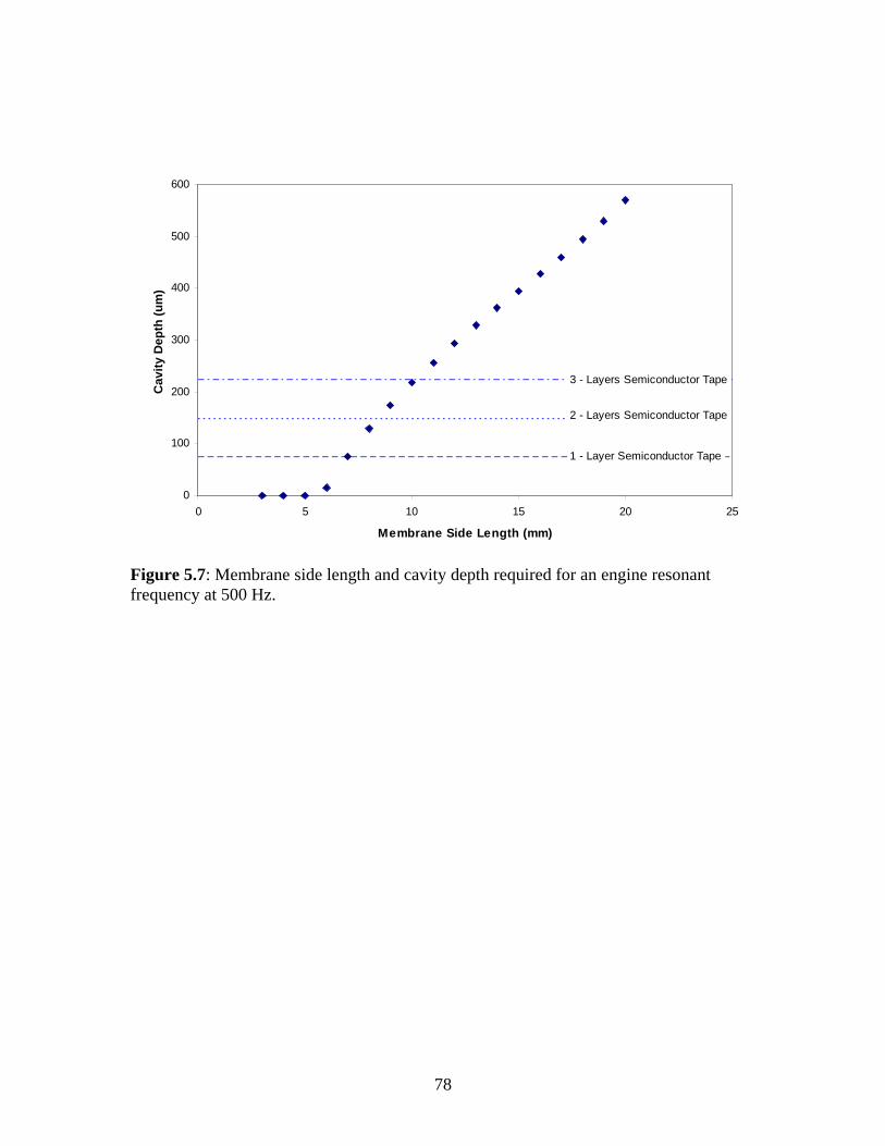
78
0
100
200
300
400
500
600
0 5 10 15 20 25
Membrane Side Length (mm)
Cav
ity
Dep
th (
um
)
3 - Layers Semiconductor Tape
2 - Layers Semiconductor Tape
1 - Layer Semiconductor Tape
Figure 5.7: Membrane side length and cavity depth required for an engine resonant frequency at 500 Hz.

79
CHAPTER 6
CONCLUSIONS AND RECOMENDATIONS
6.1 MEASURING RESONANT FREQUENCY
It has been demonstrated that the first resonant mode of vibration for the P3 micro
engine can be measured using either a forced-vibration method or a free-vibration
method. The forced vibration method involves measuring the vibration amplitude of a
generator membrane loaded in an engine as a forcing frequency is applied through the
piezoelectric effect of the generator. By measuring the frequency response to a range of
frequencies from 2 kHz to 16 kHz, an engine with a 3 mm generator membrane, 150 mm
cavity depth, and a 500 µm bubble diameter was shown to have a resonant frequency of
10.1 kHz.
A free-vibration method was also developed to determine the first resonant mode
of the engine. This method involved applying an “impact” force to the engine in order
measure the “after-ringing” response of the membrane generator. The resonant frequency
was then found by fitting a damped sinusoidal function to the “after-ringing” response.
The free vibration response of an engine assembled with a 3 mm generator, 150 mm
cavity depth, and a 500 µm bubble diameter showed a beating effect most likely due
interfering resonant frequency effects from the heater membrane. However, an FFT of
the “after-ringing” response showed that the free vibration test could duplicate the forced
vibration experiment. In order to eliminate the beating effect an alternate engine
configuration was used. This showed that an engine with a silicon membrane of 4 mm
side length and 2.2 µm thickness, assembled with a 150 mm cavity depth and an 1170

80
mm bubble diameter had a resonant frequency of 2037 Hz without noticeable beating.
The repeatability of the free vibration test in this configuration was found to be ± 8.6%.
6.2 RESONANT FREQUENCY PARAMETRIC STUDY
Three engine parameters were chosen for their likelihood to influence engine
resonant frequency. Namely, the membrane side-length, fluid/vapor ratio as defined by
the bubble size, and cavity depth were investigated.
Membrane sizes of 3 mm, 4 mm, 6 mm, and 8 mm were fabricated and assembled
in engines. As hypothesized, the resonant frequency dropped as membrane side length
increased. Engines assembled with 3 mm silicon membranes, 150 µm cavity depth, and
varying bubble size had an average resonant frequency of 2550 Hz. Engines assembled
with the same cavity depth and membrane side lengths of 4 mm, 6 mm, and 8 mm had
average resonant frequencies of 1615 Hz, 742 Hz, and 416 Hz, respectively. These,
results show that tailoring the membrane side length for the specific operating frequency
requirements of the engine can effectively control the resonant frequency of the engine to
frequencies below 500 Hz.
Bubble diameter was shown to have a small effect on the resonant frequency of
the engine. Engines assembled with a 4 mm silicon membrane, 75 µm cavity depth, and
varying bubble diameter had resonant frequencies varying from 1110 Hz to 1330 Hz.
This showed only ± 8.2% maximum control from a mean of 1208 Hz for bubble
diameters ranging from 475 µm to 1500 µm. Because the range of control in bubble
diameter is on order with the repeatability error of the free vibration test, at 8.6%, there is

81
question as to what degree the bubble diameter can be used to perform even small tuning
of resonant frequency in the engine.
Three engine cavity depths at 75 µm, 150 µm, and 225 µm for engines assembled
with 4 mm silicon membranes and varying bubble diameter. An increase in resonant
frequency was seen as the cavity depth was increased. The mean resonant frequencies
with 95% confidence for the 75 µm, 150 µm, and 225 µm cavity depths were 1206 ± 206
Hz, 1615 ± 154 Hz, and 2081 ± 291 Hz, respectively. These results show that cavity
depth is an effective means of controlling engine resonant frequency.
6.3 AVMI MODEL
The AVMI model was developed in an attempt to quantify the effects of
membrane size, bubble diameter, and cavity thickness as virtual mass additions to the
relative membrane vibrating in a vacuum. The model operates under the principle that
the resonant frequency in a fluid can be related to the resonant frequency in a vacuum by
a ratio of each systems kinetic energy. The actual kinetic energy of the fluid-membrane
coupling is extremely difficult to solve computationally, therefore the added virtual mass
ratio was determined experimentally in two stages. First, the effect of the bubble size
was calculated based on the quantity of liquid in contact with the membrane. Then, the
effect of the cavity depth was solved from experiments. The cavity depth and bubble
diameters effects on resonant frequency were shown to act independently. Results
showed that the AVMI parameters dependent on bubble diameter and cavity thickness
could be used to predict the resonant frequency of various engine configurations,
including changes in membrane size, cavity depth, and bubble diameter. Also, the model

82
was used to predict the geometry of engine configurations capable of achieving a 500 Hz
operating resonant frequency frequency.
6.4 RECOMENDATIONS
One of the most promising methods of controlling resonant frequency was shown
to be the membrane side length. However, the greatest challenge in testing membranes
over 4 mm was the inability to achieve an adequate seal. Other sealing methods have
been attempted including SU-8 resist, various tapes, and silicone rubber with limited
success. Also, it has been noted that clamping conditions seem to have a dramatic impact
on sealing, because the current carriers in use make it difficult to ensure parallel clamping
necessary for a good seal. Therefore there are two paths that may be taken to ensure
sealing for large membranes. First, an appropriate gasket material, gasket geometry, or
alternative engine fabrication process must be employed to develop a sealed cavity. The
second possibility is to improve the carrier clamping method to ensure parallel clamping.
Once a method has been developed to provide adequate sealing, a large
membrane (~7 mm) with a reasonably small cavity thickness (~75 µm) should allow for
operation of the engine at a resonant frequency near 500 Hz. The engine should then be
able to run continuously, albeit at a limited capacity due to insufficient heat rejection.
The next logical step is to integrate active cooling of the engine to allow continuous
operation and definition of a working thermodynamic cycle. Once a cycle is achieved,
the membrane geometry and engine parameters should be optimized in order to provide
sufficient inertia for the compression and expansion strokes, as well as overall efficiency.

83
While the method for active cooling is under development a study should be run
to quantify the mechanical losses within the engine. Losses within the engine are
suspected to be primarily a result of damping due to the fluid viscosity contributions. A
free-vibration test can be used to measure system damping, and an energy balance can be
used to determine the system loss during free-vibration. In order to do this effectively, an
assembly method must be developed to have better control over engine parameters. Most
notably, the initial static deflection of the upper membrane must be consistently
controlled to a minimum. Also, a method must be developed to accurately control the
fluid/vapor ratio. Once engine losses are quantified, a study should be done to optimize
the specific operating resonant frequency resulting in the lowest possible mechanical
losses.
The parameters investigated within this research were shown to primarily control
the overall mass of the engine system. An additional parameter should also be
investigated to determine the effect of system stiffness by controlling the membrane
residual stress. This can be accomplished by altering the membrane material, processing,
or additional layers to control the composite stiffness.

84
REFERENCES
1. C. Grosjean, X. Yang, Y. Tai, “A Practical Thermopneumatic Valve”, Proceedings of the 12th IEEE International Conference on Micro Electro Mechanical Systems, 147-152 (1999).
2. X. Yang, C. Grosjean, Y-C. Tai, C-M. Ho, “A MEMS Thermopneumatic Silicone
Membrane Valve”, Proceedings of the IEEE Micro Electro Mechanical Systems (MEMS), 114-118 (1997).
3. C. Grosjean, Y.C. Tai, “A Thermopneumatic Peristaltic Micropump”,
Proceedings of the International Conference on Solid-State Sensors and Actuators, 1776-1779 (1999).
4. O.C. Jeong, S.S. Yang, “Fabrication and Test of a Thermopneumatic Micropump
with a Corrugated p+ Diaphragm”, Sensors and Actuators 83, 249-255 (2000). 5. F.C.M. Van De Pol, H.T.G Van Lintel, M. Elwenspoek, J.H.J Fluitman, “A
Thermopneumatic Micropump Based on Micro-engineering Techniques”, Sensors and Actuators A 21-23, 198-202 (1990).
6. M. Carmona, S. Marco, J. Samitier, J.R. Morante, “Dynamic Simulations of
Micropumps”, Journal of Micromechanics and Microengineering 6, 128-130 (1996).
7. M. Carmona, S. Marco, J. Samitier, “Modeling the Thermal Actuation in a
Thermo-Pneumatic Micropump”, Journal of Electronic Packaging 125, 527-530 (2003).
8. C.D. Richards, D.F. Bahr, R.F. Richards, “A Micro Heat Engine for MEMS
Power”, American Society of Mechanical Engineers, Fluids Engineering Division (Publication) FED 258, 501-509 (2002).
9. J. McEntee, L. Bowman, “Oscillating Diaphragms”, Proceedings of the
International Conference on Modeling and Simulation of Microsystems 2, 597-600 (1999).
10. S. Kang, S. Tsai, H. Chen, “Fabrication and Test of Radial Grooved Micro Heat
Pipes”, Applied Thermal Engineering 22, 1559-1568 (2002). 11. P.D. Dunn, D.A. Reay, Heat Pipes, Pergamon, Oxford, 4-5 (1994). 12. B. Marland, D. Bugby, C. Stouffer, “Development and Testing of Advanced
Cryogenic Thermal Switch Concepts”, Proceedings of the Space Technology and Applications International Forum, 837-846 (2000).

85
13. A.O. Christensen, J.P. Jacob, C.D. Richards, D.F. Bahr, R.G. Richards, “Fabrication and Characterization of a Liquid-Metal Micro-Droplet Thermal Switch”, Proceedings of Transducers’03, Paper No. AM069, Boston, (2003).
14. C.D Richards, D.F. Bahr, C.-G. Xu, R.F. Richards, “MEMS Power: The P3
System”, Proceedings of the Intersociety Energy Conversion Engineering Conference 2, 803-814 (2001).
15. S. Whalen, M. Thompson, D.F. Bahr, C.D. Richards, R.F. Richards, “Design,
Fabrication, and Testing of the P3 Micro Heat Engine”, Sensors and Actuators A 104, 290-298 (2003).
16. L.S. Pan, T.Y. Ng, X.H. Wu, H.P. Lee, “Analysis of Valveless Micropumps with
Inertial Effects”, Journal of Micromechanics and Microengineering 13, 390-399 (2003).
17. A. Ullmann, I. Fono, “The Piezoelectric Valve-Less Pump – Improved Dynamic
Model”, Journal of Microelectromechanical Systems 11, 655-664 (2002). 18. J-H. Park, K. Yoshida, S. Yokota, “Resonantly Driven Piezoelectric Micropump
Fabrication of a Micropump Having High Power Density”, Mechatronics 9, 687-702 (1999).
19. A. Caronti, G. Caliano, A. Iula, M. Pappalardo, “An Accurate Model for
Capacitive Micromachined Ultrasonic Transducers”, IEEE Transactions on Ultrasonics, Ferroelectrics, and Frequency Control 49, 159-168 (2002).
20. J, Hietanen, Capacitive Ultrasonic Transducers: Their Parameters and Testing,
Acta Scandinavica, Applied Physics Series No. 209, Helsinki (1999). 21. S.T. Hansen, A. Turo, F.L. Degertekin, B.T. Khuri-Yakub, “Characterization of
Capacitive Micromachined Ultrasonic Transducers in Air Using Optical Measurements”, Proceedings of the IEEE Ultrasonics Symposium, 947-950 (2000).
22. E. Defay, C. Millon, C. Malhaire, D. Barbier, “PZT Thin Films Integration for
the Realisation of a High Sensitivity Pressure Microsensor Based on a Vibrating Membrane”, Sensors and Actuators A 99, 64-67 (2002).
23. G. Caliano, N. Lamberti, A. Iula, M. Pappalardo, “A Piezoelectric Bimorph Static
Pressure Sensor”, Sensors and Actuators A 46-47, 176-178 (1995). 24. R.L. Bardell, N.R. Sharma, F.K. Forster, M.A. Afromowitz, R.J. Penney,
“Designing High-Performance Micro-Pumps Based on No-Moving-Parts Valves”, ASME, Dynamic Systems and Control Division DSC, v 62, Microelectromechanical Systems (MEMS), 47-53 (1997).

86
25. J.W.S. Rayleigh, The Theory of Sound, Volume 1, Dover Publications, New York
(1945). 26. S. Timoshenko, S. Woinowsky-Krieger, Theory of Plates and Shells, McGraw-
Hill, New York (1959). 27. R. Paneva, D. Gotchev, “Non-Linear Vibration Behavior of Thin Multilayer
Diaphragms”, Sensors and Actuators A 72, 79-87 (1999). 28. K. El Bikri, R. Benamar, M. Bennouna, “Geometrically Non-Linear Free
Vibrations of Clamped Simply Supported Rectangular Plates. Part I: The Effects of Large Vibration Amplitudes on the Fundamental Mode Shape”, Computers and Structures 81, 2029-2043 (2003).
29. H. Koivurova, A. Pramila, “Nonlinear Vibration of Axially Moving Membrane by
Finite Element Method”, Computational Mechanics 20, 537-581 (1997). 30. W.A. Moussa, U.F. Gonzalez, “Simulation of MEMS Piezoelectric Micropump
for Biomedical Applications”, Proceedings of the International Mechanical Engineering Congress and Exposition, 187-192 (2002).
31. A. Olsson, G. Stemme, E. Stemme, “The First Valve-Less Diffuser Gas Pump”,
Proceedings of the IEEE Micro Electro Mechanical Systems (MEMS), 108-113 (1997).
32. P. Rangsten, L. Smith, L. Rosengren, B. Hok, “Electrostatically Excited
Diaphragm Driven as a Loudspeaker”, Sensors and Actuators A 52, 211-215 (1996).
33. G.T.A. Kovacs, Micromachined Transducer Sourcebook, McGraw Hill, Boston,
289-295 (1998). 34. M. Arik, S.M. Zurn, K.S. Yigit, A. Bar-Cohen, “Design, Fabrication and
Experimental-Numerical Study of PZT Sensors”, Proceedings of the International Conference on Modeling and Simulation of Microsystems, 574-578 (2000).
35. R.D. Blevins, Formulas for Natural Frequency and Mode Shape, Van Nostrand
Reinhold Co., New York, 224-232, 386-424 (1979). 36. B. de Heij, B. van der Schoot, N.F. de Rooij, H. Bo, J. Hess, “Modelling and
Optimisation of a Vaporiser for Inhalation Drug Therapy”, Proceedings of the International Conference on Modeling and Simulation of Microsystems, 542-545 (1999).

87
37. S.C. Ko, Y.C. Kim, S.S. Lee, S.H. Choi, S.R. Kim, “Micromachined Piezoelectric Membrane Acoustic Device”, Sensors and Actuators A 103, 130-134 (2003).
38. P. Muralt, A. Kholkin, M. Kohli, T. Maeder, “Piezoelectric Actuation of PZT
Thin-Film Diaphragms at Static and Resonant Conditions”, Sensors and Actuators A 53, 398-404 (1996).
39. J. Thomas, R. Kuhnhold, R. Schnupp, G. Temmel, H. Ryssel, “Simulation of the
Production of Functional Layers for Vibration Sensors for Tool State Monitoring and Finite Element Analysis of Mechanical Characteristics”, Proceedings of the International Conference on Modeling and Simulation of Microsystems 2, 593-596 (1999).
40. A. Degen, N. Abedinov, T. Gotszalk, E. Sossna, M. Kratzenberg, I.W. Rangelow,
“Stress Analysis in Si Membranes for Open Stencil Masks and Mini-Reticles Using Double Bulging and Resonant frequency Methods”, Microelectronic Engineering 57-58, 425-432 (2001).
41. M.S. Kennedy, D.F. Bahr, C.D. Richards, R.F. Richards, “Residual Stress Control
to Optimize PZT MEMS Performance”, Proceedings of the Materials Research Society Symposium 741, 163-168 (2002).
42. J.S. Kim, K. Choi, I. Yu, “A New Method of Determining the Equivalent Circuit
Parameters of Piezoelectric Resonators and Analysis of the Piezoelectric Loading Effect”, IEEE Transactions on Ultrasonics, Ferroelectrics, and Frequency Control 40, 424-426 (1993).
43. L. Pizarro, D. Certon, M. Lethiecq, O. Boumatar, B. Hosten, “Experimental
Investigation of Electrostatic Ultrasonic Transducers with Grooved Backplates”, Proceedings of the IEEE Ultrasonics Symposium 2, 1003-1006 (1997).
44. J. Billingham, “Modelling the Response of a Vibrating-Element Density Meter in
a Two-Phase Mixture”, Journal of Fluid Mechanics 340, 343-360 (1997). 45. D. Crescini, D. Marioli, A. Taroni, “Piezoelectric Thick-Film Fluid Density
Sensor Based on Resonant frequency Vibration”, Proceedings of the IEEE Instrumentation and Measurement Technology Conference, 1368-1371 (1998).
46. C.T. Crowe, D.F. Elger, J.A. Roberson, Engineering Fluid Mechanics, 7th Ed.
John Wiley and Sons. (2001). 47. S.Inaba, K. Akaishi, T. Mori, K. Hane, ”Analysis of the Resonant frequency
Characteristics of a Cantilever Vibrated Photothermally in a Liquid”, Journal of Applied Physics 73, 2654-2658 (1993).

88
48. H. Lamb, “On the Vibrations of an Elastic Plate in Contact with Water”, Proceedings of The Royal Society 98, 205-216 (1920).
49. M.K. Kwak, K.C. Kim, “Axisymmetric Vibration of Circular Plates in Contact
with Fluid”, Journal of Sound and Vibration 146, 381-389 (1991). 50. M.K. Kwak, “Vibration of Circular Membranes in Contact with Water”, Journal
of Sound and Vibration 178, 688-690 (1994). 51. M.S. Weinberg, C.E. Dube, A. Petrovich, A.M. Zapata, “Fluid Damping in
Resonant Flexural Plate Wave Device”, Journal of Microelectromechanical Systems 12, 567-596 (2003).
52. M. Amabili, “Effect of Finite Fluid Depth on the Hydroelastic Vibrations of
Circular and Annular Plates”, Journal of Sound and Vibration 193, 909-925 (1996).
53. A. Prak, F.R. Blom, M. Elwenspoek, T.S.J. Lammerink, “Q-Factor and Frequency
Shift of Resonating Silicon Diaphragms in Air”, Sensors and Actuators A 25-27, 691-698 (1991).
54. Y.K. Cheung, D. Zhou, “Coupled Vibratory Characteristics of a Rectangular
Container Bottom Plate”, Journal of Fluids and Structures 14, 339-357 (2000). 55. Y. Fu, W.G. Price, “Interactions Between a Partially or Totally Immersed
Vibrating Cantilever Plate and the Surrounding Fluid”, Journal of Sound and Vibration 118, 495-513 (1987).
56. G. Muthuveerappan, N. Ganesan, M.A. Veluswami, “Note on Vibration of a
Cantilever Plate Immersed in Water”, Journal of Sound and Vibration 63, 385-391 (1979).
57. M.S. Marcus, “Finite-Element Method Applied to the Vibration of Submerged
Plates”, Journal of Ship Research 22, 94-99 (1978). 58. T. Naik, E.K. Longmire, S.C. Mantell, “Dynamic Response of a Cantilever in
Liquid Near a Solid Wall”, Sensors and Actuators A 102, 240-254 (2003). 59. F. Montero de Espinosa, J.A. Gallego-Juarez, “On the Resonant frequency
Frequencies of Water-Loaded Circular Plates”, Journal of Sound and Vibration 94, 217-222 (1984).
60. L. Jezequel, “Hydrodynamic Added-Mass Identification from Resonance Tests”,
AIAA Journal 21, 608-613 (1983).

89
61. A. Olsson, G. Stemme, E. Stemme, “A Valve-Less Planar Fluid Pump with Two Pump Chambers”, Sensors and Actuators A 46-47, 549-556 (1995).
62. L.S. Pan, T.Y. Ng, G.R. Liu, K.Y. Lam, T.Y. Jiang, “Analytical Solutions for the
Dynamic Analysis of a Valveless Micropump – a Fluid-Membrane Coupling Study”, Sensors and Actuators A 93, 173-181 (2001).
63. S. Inaba, K. Hane, “Dependence of Resonant frequency Frequency of a
Membrane Vibrated Photothermally on Pressure and Geometry in a Low-Vacuum Region”, Japanese Journal of Applied Physics 32, 1001-1004 (1993).
64. J. Mertens, E. Finot, T. Thundat, A. Fabre, M-H. Nadal, V. Eyraud, E. Bourillot,
“Effects of Temperature and Pressure on Microcantilever Resonant frequency Response”, Ultramicroscopy 97, 119-126 (2003).
65. W.P. Lai, W. Fang, “A Novel Antistiction Method Using Harmonic Excitation on
the Microstructure”, Journal of Vacuum Science Technology A 19, 1224-1228 (2001).
66. T. Abe, W.C. Messner, M.L. Reed, “Effects of Elevated Temperature Treatments
on Microstructure Release Procedures”, Journal of Microelectromechanical Systems 4, 66-75 (1995).
67. M.K. Kwak, S.-B. Han, “Effect of Fluid Depth on the Hydroelastic Vibration of
Free-Edge Circular Plate”, Journal of Sound and Vibration 230, 171-185 (2000). 68. A. Olson, MS Thesis, Washington State University (2003). 69. J. Kanyer, MS Thesis, Washington State University (2003). 70. K. Bruce, R. Richards, D. Bahr, C. Richards, “Characterization of a Piezoelectric
Membrane for MEMS Power”, Proceedings of ASME International Mechanical Engineering Congress and Exposition 3, 21-28 (2001).
71. Polytec GmbH, User Manual: Vibrometer Controller OFV-5000, Waldronn,
Germany. (2003). 72. F.P. Beer, E.R. Johnston, Vector Mechanics for Engineers: Dynamics, 6th Ed.
McGraw Hill, (1997). 73. J.H. Cho, M.J. Anderson, D.F. Richards, D.F. Bahr, C.D. Richards, "Analysis of
Micromachined PZT Membranes for MEMS Power," Proceedings of Nanotech’04 1, 382-385 (2004).
74. R. Szilard, Theory and Analysis of Plates: Classical and Numerical Methods,
Prentice Hall, 421 (1974).

90
75. Internet Source: “Experiment 31: Using Excel to Compute FFT”,
http://www.mme.wsu.edu/~me305/exp31.htm 76. S.A. Whalen, M.R. Thompson, C.D. Richards, D.F. Bahr, R.F. Richards, “Low
Frequency Operation of the P3 Micro Heat Engine”, Proceedings of International Mechanical Engineering Congress and Exposition, 469-476 (2002).
77. A.J. Wheeler, A.R. Ganji, Introduction to Engineering Experimentation, Prentice
Hall, Upper Saddle River, New Jersey, 138-163 (1996).