
Building Relationships and Resolving Conflicts: Infusing ...

The University of Manchester Research
Resolving Performance Conflicts In New Wind TurbineBlade Designs
Link to publication record in Manchester Research Explorer
Citation for published version (APA):Peesapati, V., Cotton, I., Rashid, L. S., Brown, A., Jamshidi, P., & Hogg, P. J. (2009). Resolving PerformanceConflicts In New Wind Turbine Blade Designs. In European Wind Energy Conference and Exhibition 2009 (Vol. 1,pp. 260-287)
Published in:European Wind Energy Conference and Exhibition 2009
Citing this paperPlease note that where the full-text provided on Manchester Research Explorer is the Author Accepted Manuscriptor Proof version this may differ from the final Published version. If citing, it is advised that you check and use thepublisher's definitive version.
General rightsCopyright and moral rights for the publications made accessible in the Research Explorer are retained by theauthors and/or other copyright owners and it is a condition of accessing publications that users recognise andabide by the legal requirements associated with these rights.
Takedown policyIf you believe that this document breaches copyright please refer to the University of Manchester’s TakedownProcedures [http://man.ac.uk/04Y6Bo] or contact [email protected] providingrelevant details, so we can investigate your claim.
Download date:12. Feb. 2022
Resolving Performance Conflicts In New Wind Turbine Blade Designs.
V. Peesapati, I Cotton
School of Electrical & Electronics Engineering, University of Manchester,
UK vidyadhar.peesapati-
[email protected] [email protected]
L. S. Rashid, A Brown School of Electrical &
Electronic Engineering University of Manchester,
P. Jamshidi, P.J. Hogg School of Material
Sciences University Of Manchester,
UK [email protected] [email protected]
l
Abstract This paper considers the various conflicts that arise in designing a wind turbine blade which satisfies the needs for enhanced structural performance and effective lightning protection whilst simultaneously providing a low radar cross section. Some novel materials solutions to these three problems are presented and empirical data will be used to develop routes to optimising the various properties provided. A key factor will be the ability to incorporate any potential solution within a low cost manufacturing system without introducing any significant weight penalty to the final manufactured blade. This work was funded by EPSRC under its Supergen initiative. Keywords: Wind Turbine, Lightning Protection, Radar Absorbing Materials (RAM), composite, radar-reflective surface.
1 Introduction Wind farm planning applications submitted to regional agencies for consideration in the UK often raise objections on the basis of the potential for radar interference due to their large radar cross section (RCS). According to the Global Wind Energy Council, the total installed capacity of wind power around the world reached a massive 60000MW at the end of 2005, a 12 fold increase, in comparison to 1995 [1]. By the end of 2007 this number reached a massive 94 Gigawatts [2]. With the increase in U.K power needs and the governments’ target of reaching 10% of the countries electricity needs through renewable sources by 2010 [9] there is a large increase in plans for
installing larger offshore wind farms. Thus the challenge of tackling the problem of wind farm radar interference is now becoming essential. Air Traffic Control (ATC) and Air Defense (AD) radars employ moving target detection (MTD) based on Doppler shift as a mean of non-stationary target detection against a static background [17]. . The blades generate variable Dopler returns based on the angle of the plane of the blades relative to the radar [14], the length of blade and the speed of rotation of the turbine. Hence, wind turbines may generate false tracks or cause successfully established tracks to be lost as targets approach wind farms [16]. Investigating into the interference of wind farms on ships radar (which does not use Doppler)has confirmed that there is a significant impact as a wind farm will in general produce spurious returns on radar displays caused by multiple reflection from the static towers, as well as the rotating blades. Other effects such as beam spreading and side lobe detection due to the very high radar cross section of wind turbines [11,12] are also observed Introducing filters into the radar signal processing in the affected radars reduces Doppler interference, but does not completely resolve the problem. Hence, there is a need to reduce the RCS by alternative means such as applying radar absorbing materials (RAM) to the blades and nacelle and by careful consideration of the tower design Ideally RAM solutions would be light and thin to maintain the design profile of the turbine blade and avoid and significant weight
increase. One possible absorber design is based on a resonant structure formed between an absorbing surface and a thin metallic layer buried within the composite structure of the blade laminate. This resonant structure offers compactness and low weight but the integral metallic layer may cause a considerable effect on
• Structural integrity of the blade. • Complexity and cost of the
manufacturing process. • The lightning protection system.
The present paper is aimed at examining the issues that result in the need to develop optimal solutions that can maintain lighting protection, minimise RCS and retain structural integrity – all within a neutral cost environment. Tests have been performed on hybrid material forms, suitable to be added to the blade laminate using existing manufacturing systems and which can be used as radar reflective surfaces.
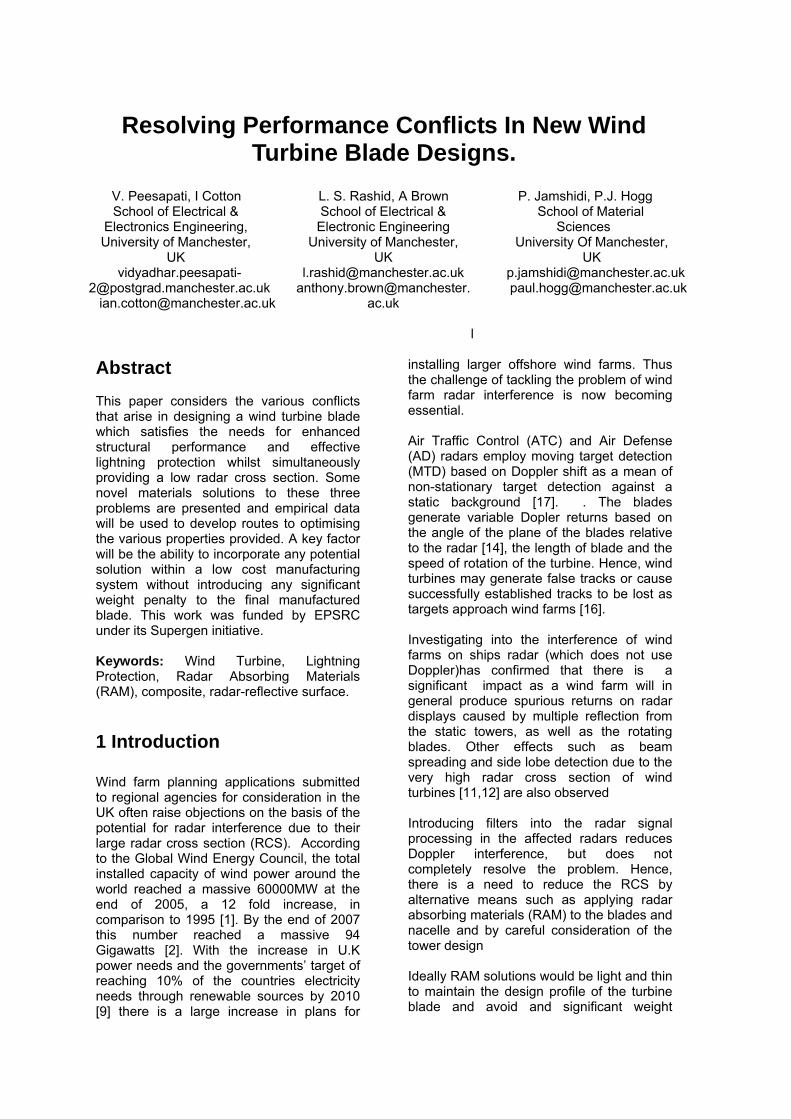
2 Wind Turbine RCS & Reduction Wind turbines are large structures that are typically made of GRP and/or carbon fibre composite components mounted on steel towers. Full physical optics modeling of a typical 40 meter bladed turbine [13,14,18] at various rotation and yaw angles using the coordinate system shown in figure 1 was undertaken. The results show that the RCS can be in the order of 60 dBms (106 m2) at 9.4 GHz, which is of the same order as a large oil tanker broadside on. It was found that the tower constitutes by far the largest source of scatter (approx. 80%) followed by the blades (5% each). The nacelle was only considered to be a significant source of scatter for 90
o yaw case
(i.e. broadside on). The nosecone was found to be largely insignificant at all angles [14].
Figure 1 RCS Modeling Coordinate System
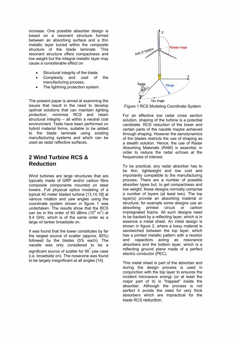
For an effective low radar cross section solution, shaping of the turbine is a potential candidate. RCS reduction of the tower and certain parts of the nacelle maybe achieved through shaping. However the aerodynamics of the blades restricts the use of shaping as a stealth solution. Hence, the use of Radar Absorbing Materials (RAM) is essential, in order to reduce the radar echoes at the frequencies of interest. To be practical, any radar absorber has to be thin, lightweight and low cost and importantly compatible to the manufacturing process. There are a number of possible absorber types but, to get compactness and low weight, these designs normally comprise a number of layers (at least two). The top layer(s) provide an absorbing material or structure; for example some designs use an absorbing printed circuit or carbon impregnated foams. All such designs need to be backed by a reflecting layer, which is in essence a metal sheet. An initial design is shown in figure 2, where a lossy material is sandwiched between the top layer, which has a printed metallic pattern with a resistor and capacitors acting as resonance absorbers and the bottom layer, which is a reflecting ground plane made of a perfect electric conductor (PEC). This metal sheet is part of the absorber and during the design process is used in conjunction with the top layer to ensures the incident microwave energy (or at least the major part of it) is "trapped" inside the absorber. Although the process is not perfect it avoids the need for very thick absorbers which are impractical for the blade RCS reduction.
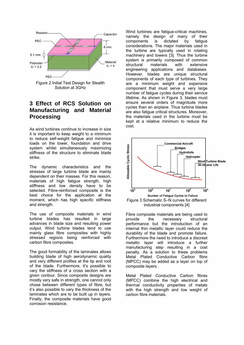
Figure 2 Initial Test Design for Stealth
Solution at 3GHz
3 Effect of RCS Solution on Manufacturing and Material Processing As wind turbines continue to increase in size it is important to keep weight to a minimum to reduce self-weight fatigue and minimize loads on the tower, foundation and drive system whilst simultaneously maximizing stiffness of the structure to eliminate blade strike. The dynamic characteristics and the stresses of large turbine blade are mainly dependent on their masses. For this reason, materials of high fatigue strength, high stiffness and low density have to be selected. Fibre-reinforced composite is the best choice for the application at the moment, which has high specific stiffness and strength. The use of composite materials in wind turbine blades has resulted in large advances in blade size and resulting power output. Wind turbine blades tend to use mainly glass fibre composites with highly stressed regions being reinforced with carbon fibre composites. The good formability of the laminates allows building blade of high aerodynamic quality and very different profiles at the tip and root of the blade. Furthermore, it’s possible to vary the stiffness of a cross section with a given contour. Since composite designs are mostly very safe in strength, one cannot only chose between different types of fibre, but it’s also possible to vary the thickness of the laminates which are to be built up in layers. Finally, the composite materials have good corrosion resistance.
Wind turbines are fatigue-critical machines, namely the design of many of their components is dictated by fatigue considerations. The major materials used in the turbine are typically used in rotating machinery and towers [3]. Thus the turbine system is primarily composed of common structural materials with extensive engineering applications and databases. However, blades are unique structural components of each type of turbines. They are a minimum weight and expensive component that must serve a very large number of fatigue cycles during their service lifetime. As shown in Figure 3, blades must ensure several orders of magnitude more cycles than an airplane. Thus turbine blades are also fatigue critical structures. Moreover, the materials used in the turbine must be kept at a relative minimum to reduce the cost.
Figure 3 Schematic S–N curves for different
industrial components [4]
Fibre composite materials are being used to provide the necessary structural performance but the introduction of an internal thin metallic layer could reduce the durability of the blade and promote failure. Furthermore the need to introduce a discreet metallic layer will introduce a further manufacturing step resulting in a cost penalty. As a solution to these problems Metal Plated Conductive Carbon fibre (MPCC) may be added as a layer on top of composite layers . Metal Plated Conductive Carbon fibres (MPCC) combine the high electrical and thermal conductivity properties of metals with the high strength and low weight of carbon fibre materials.
This material can range from 10%-65% metal by weight. Nickel and Copper/Nickel hybrids have been the primary metals of choice but the process can be adapted to plate other metals such as silver, gold, platinum and palladium. Comparative Scanning Electron Micrographs (SEM) & EDX has been used in to characterize these veils. Figure 4 shows the 100kg/m2
MPCC under SEM microscopy.
Figure 4 a micrograph of 100 Kg/m2 MPCC
under SEM Qualitative characterization by EDX method shows that fibres in MPCC veils have been coated by Nickel and copper as described before (Figure 5).
Figure 5 EDX characterization of MPCC
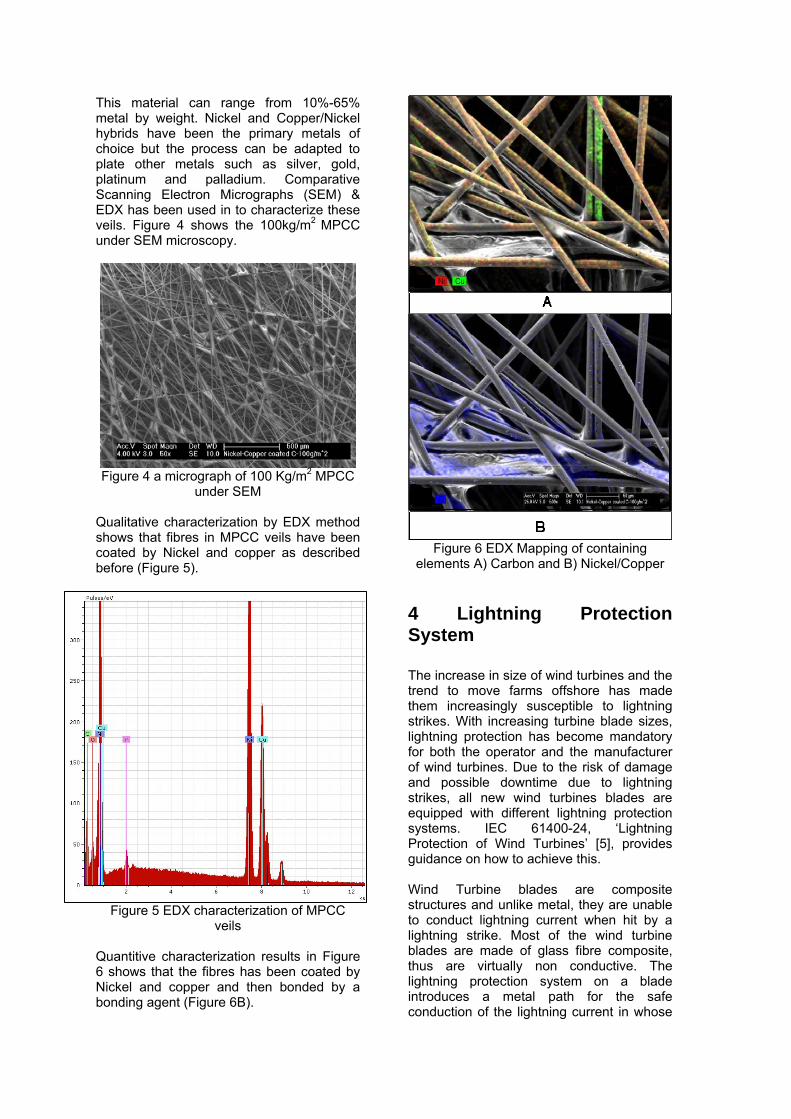
veils Quantitive characterization results in Figure 6 shows that the fibres has been coated by Nickel and copper and then bonded by a bonding agent (Figure 6B).
Figure 6 EDX Mapping of containing
elements A) Carbon and B) Nickel/Copper
4 Lightning Protection System The increase in size of wind turbines and the trend to move farms offshore has made them increasingly susceptible to lightning strikes. With increasing turbine blade sizes, lightning protection has become mandatory for both the operator and the manufacturer of wind turbines. Due to the risk of damage and possible downtime due to lightning strikes, all new wind turbines blades are equipped with different lightning protection systems. IEC 61400-24, ‘Lightning Protection of Wind Turbines’ [5], provides guidance on how to achieve this. Wind Turbine blades are composite structures and unlike metal, they are unable to conduct lightning current when hit by a lightning strike. Most of the wind turbine blades are made of glass fibre composite, thus are virtually non conductive. The lightning protection system on a blade introduces a metal path for the safe conduction of the lightning current in whose

absence the current could severely damage the blade. If a component of a wind turbine is damaged there are two things that need to be considered, the resulting repair costs and the associated loss in production caused due to downtime. Given the move of wind turbines to offshore locations and the need to mobilise special floating cranes, these costs and repair times will only have increased in recent years. The wind turbine blades are said to be the most expensive parts on a wind turbine if needed to be replaced [6], thus is vital to avoid any kind of damage to the wind turbine blades. The different types of lightning protection typically installed in wind turbines blades are [5] shown in figure 7. A system that is widely used is the internal lightning protection system consisting of an internal lightning down conductor capable of carrying the lightning current. Metal receptors (figure 7) which act as air terminations penetrate the blade surface and are then connected to the down conductor. This system of external receptors connected to an internal downconductor is being widely used for blades upto 60m [5] and this system does not look likely to be changed for longer future blades. Current lightning protection systems for rotor blades are designed to withstand 98% of lightning
strikes [6] but there is still a risk of damage, particularly at the attachment point. If lightning attaches to an area which is not designed for lightning attachment, considerable damage at the point of attachment can be observed. This damage can be seen in the form material degradation, burns, surface erosion and punctures. More information regarding the types of lightning damage that have been observed in wind turbines is available in [6-8].
4.1 Effect of RCS Solution on Lightning Protection System The introduction of a thin metallic layer within the blade, that consists an internal lightning down conductor and receptors as a lightning protection system, could result in a change to the efficiency of the lightning protection system through a modification of the electric field around the receptor. In addressing the effect of the RAM solution to Wind Turbine blades, two areas of the lightning protection system are considered; the impact of the RAM on lightning attachment points and the impact of the RAM on lightning current conduction.
Figure 7 Lightning Protection Methods of Wind Turbine Blades

A B C
Figure 8 Effect of Conductive Layer on LPS (receptor penetrates blade laminate, but this is concealed due to field enhancement patch)
4.1.1 Impact of RAM on Lightning Attachment Points The efficiency of the lightning Protection System is dependant on the effectiveness of the air termination points. In the case of the lightning protection system considered in this paper, these are the receptors. The number of receptors on blades varies according to different blade manufacturers. Using FEA methods the electric field enhancement at the receptor and the effect of integrating the conductive layer with the lightning protection system can be simulated. Three models have been simulated using FEA methods. The FEA Software used was Opera 3D. The 3D-models used in this paper were developed using the modeler package available in the software. The models were later subjected to electro-static analysis in the pre-processor side of the software. All results are then analysed in the post-processor section of the software. In two of these models the conductive layer needed for the RAM solution has been integrated along with the existing lightning protection system. All the models are subjected to the same uniform electric field. The initial model (Figure 8A) is the case of a standard wind turbine blade with a receptor that is connected to a down conductor. In this simulation it can be observed that the point of highest electric field enhancement is the receptor made out of copper. Thus, theoretically this should be the first place for streamer inception.
The next two simulations show the case where a conductive layer, intended for the RAM solution as a reflective service, is placed inside the blade laminate. In the initial case this conductive layer is extended to the tip of the blade, and in the next the conductive layer stops right below the tip receptor. In the first case with the conductive layer placed under the blade laminate (Figure 8B), it can be seen that the receptor is not the area of high field enhancement any more and instead there is a high electric field enhancement at the tip of the blade. This is undesirable, as this increases the risk of lightning attachment to areas of the blade away from the receptor and possible damage due to the same. In figure 8C, where the layer stops below the receptor, the electric field enhancement is still the highest at the receptor. However, the ratio of the field enhancement at the receptor to that of the tip of the blade in figure 8C is lower than the case where there is no internal reflective layer (Figure 8A), thus increasing the chances of a lighting attachment away from the receptor. Thus from Figure 8C, adding the conductive layer below the receptor will make it easier to integrate it with the lightning protection system, but there still would be a significant decrease in the efficiency of receptor.
4.1.2 Impact of RAM on Lightning Current Conduction Once lightning attachment is established the next purpose of the lightning protection system is to carry lightning current. Existing
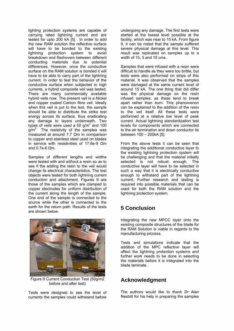
lighting protection systems are capable of carrying rated lightning current and are tested for upto 200 kA [5]. In order to add the new RAM solution the reflective surface will have to be bonded to the existing lightning protection system to avoid breakdown and flashovers between different conducting materials due to potential differences. However, once the conductive surface on the RAM solution is bonded it will have to be able to carry part of the lightning current. In order to test the behavior of the conductive surface when subjected to high currents, a hybrid composite veil was tested. There are many commercially available hybrid veils now. The present veil is a Nickel and copper coated Carbon fibre veil. Ideally when this veil is put to the test, the sample should be able to distribute the strike test energy across its surface, thus eradicating any damage to layers underneath. Two types of veils were used a 50 g/m2 and 100 g/m2. The resistivity of the samples was measured at around 7.7 Ωm in comparison to copper and stainless steel used on blades in service with resistivities of 17.8e-9 Ωm and 0.7e-6 Ωm. Samples of different lengths and widths were tested with and without a resin so as to see if the adding the resin to the veil would change its electrical characteristics. The test objects were tested for both lightning current conduction and attachment. Figures 9 are those of the samples which are clamped to copper electrodes for uniform distribution of the current along the length of the sample. One end of the sample is connected to the source while the other is connected to the earth for the return path. Results of the tests are shown below.
Figure 9 Current Conduction Test (50g/m2
before and after test) Tests were designed to see the level of currents the samples could withstand before
undergoing any damage. The first tests were started at the lowest level possible at the facility, which was near to 15 kA. From figure 9, it can be noted that the sample suffered severe physical damage at this level. This result was replicated on samples up to a width of 15, 5 and 10 cms. Samples that were infused with a resin were difficult to handle as they were too brittle, but tests were also performed on strips of this material. It was observed that the samples were damaged at the same current level of around 15 kA. The one thing that did differ was the physical damage on the resin infused samples, as these tend to break apart rather than burn. This phenomenon can be explained to the addition of the resin to the veil itself. All these tests were performed at a relative low level of peak current. Actual lightning standardization test levels for components which are connected to the air termination and down conductor lie between 100 – 200kA [5]. From the above tests it can be seen that integrating the additional conductive layer to the existing lightning protection system will be challenging and that the material initially selected is not robust enough. The conductive layer will have to be selected in such a way that it is electrically conductive enough to withstand part of the lightning current. Further research and testing is required into possible materials that can be used for both the RAM solution and the lightning protection system.
5 Conclusion Integrating the new MPCC layer onto the existing composite structures of the blade for the RAM Solution is viable in regards to the manufacturing process. Tests and simulations indicate that the addition of the MPC reflective layer will affect the lightning protection systems and further work needs to be done in selecting the materials before it is integrated into the blade laminate.
Acknowledgment The authors would like to thank Dr Alan Nesbitt for his help in preparing the samples

and Dr Nikolaos Kokkinos of Elemko SA, Greece, for his help in testing the samples. This work has been carried out under the Supergen V Wind Energy Theme, funded by the Engineering and Physical Sciences Research Council, UK. Further information about Supergen Wind is available at http://www.supergen-wind.org.uk/
References [1]. GWEC, Global Wind Energy Outlook. 2006. [2]. EurObserv'ER, Wind Energy Barometer. SYSTÈMES SOLAIRES n° 1 7 7, 2007. [3]. Shokrieh, M.M. and R. Rafiee, Simulation of fatigue failure in a full composite wind turbine blade. Composite Structures, 2006. 74(3): p. 332-342. [4]. Herbert, J.S., A summary of the fatigue properties of wind turbine materials. Wind Energy, 2000. 3(1): p. 1-34. [5]. IEC 61400-24, I., Wind turbine generator systems – Part 24: Lightning protection for wind turbines” June 2000. [6]. Rademakers, L., et al., Lightning Damage of OWECS. 2002(Part 1: “Parameters Relevant for Cost Modelling”. [7]. Naka, T., et al., Experimental Studies on Lightning Protection Design for Wind Turbine Blades. [8]. Cotton, I., et al., Lightning Protection Of Wind Turbines - A Designers Guide To Best Practice. 1999.
[9]. “Renewables Obligation: Annual report2006-2007”, Office of Gas and Electricity Markets (Ofgem), 4 March 2008
[10]. S Appleton, “Stealthy Wind Turbines - addressing the radar issue”, BWEA28, (2006). [11]. R Baker. “BWEA Marine Radar Investigation”, BWEA28, (2006). [12]. C Brown, M. Howard, “Results of the electromagnetic investigations and assessments of marine radar, communications and position fixing systems undertaken at the North Hoyle wind farm by QinetiQ and the Maritime and Coastguard Agency”, MCA Report MNA 53/10/366, Nov 2004. [13]. H S Dabis, “Wind Turbine Electromagnetic Scatter Modelling using Physical Optics Techniques”, Renewable Energy, 16 pp. 882-887, (1999). [14]. J Pinto. “Stealth Technology for Wind Turbines - Addressing the Aviation and Marine Radar Issues”, BWEA28, (2006). [15]. C Trundle, “Primary Radar v Wind Farms: Safety Case Mitigation”, BWEA28, (2006). [16]. D M Webster, “The Effects Of Wind Turbine Farms On ATC Radar”, AWC/WAD/72/665/TRIALS, MAY 05. [17]. M I Skolnik, Introduction to Radar Systems, 2nd edition. New York: McGraw-Hill Book Company, 1980 [18]. L Rashid, A K Brown, “RCS and Radar Propagation near Offshore Wind Farms”, June 2007, Antennas & Propagation Symposium.