RESIDUAL STRESSES CAUSED BY THERMAL AND THERMOCHEMICAL SURFACE TREATMENTS T. · PDF...
27
RESIDUAL STRESSES CAUSED BY THERMAL AND THERMOCHEMICAL SURFACE TREATMENTS T. Ericsson Depar~tnent of Mechanical Engineering, Lhkoping Universify, S-X31 83 Linkoping, Sweden ABSTRACT Thermal treatments discussed in this paper are induction and laser hardening of steel and thermochemical treatments are carburizing, nitriding, nitrocarburizing and boriding of steel. The principles for the methods are briefly described and experimental data on residual stresses are reviewed. The mechanisms for the residual stress generation is then discussed in some detail supported by computer models. The effect of varying the process parameters on the residual stress is analysed. KEYWORDS Residual stress, carburizing, case hardening, induction hardening, laser hardening, nitriding, boriding. INTRODUCTION Thermal and thermochemical heat treatment of metal is usually accompanied by the evolution of large residual stresses. There are a number of reasons for this: (i) thermal stresses due to thermal expansion or contraction of a homogeneous material in a temperature gradient field, (ii) different thermal expansion coefficients of the various phases in a multiphase material, (iii) density changes due to phase transformations in the metal, (iv) growth stresses of reaction products formed on the surface or as precipitates, (v) chemical compositions gradients below the surface. In the following it will be demonstrated how these factors contribute during thermal and thermochemical surface treatments of steel. The treatments described are carburizing, induction and laser hardening, nitriding, nitrocarburizing and boriding. Several of the processes have been described recently in volume 2 of Advances in Surface Treatments (Ericsson, 1985): It is appropriate to remind the reader of some definitions. One distinguishes between macro- and micro-residual stresses or with a more elaborated classification residual stresses of the first, second and third kind. The residual stresses treated here are of the macro type equivalent to the first kind. An exception
Transcript of RESIDUAL STRESSES CAUSED BY THERMAL AND THERMOCHEMICAL SURFACE TREATMENTS T. · PDF...
RESIDUAL STRESSES CAUSED BY THERMAL AND THERMOCHEMICAL
SURFACE TREATMENTS
T. Ericsson
Depar~tnent of Mechanical Engineering, Lhkoping Universify, S-X31 83 Linkoping, Sweden
ABSTRACT
Thermal treatments discussed in this paper are induction and laser hardening of steel and thermochemical treatments are carburizing, nitriding, nitrocarburizing and boriding of steel.
The principles for the methods are briefly described and experimental data on residual stresses are reviewed. The mechanisms for the residual stress generation is then discussed in some detail supported by computer models. The effect of varying the process parameters on the residual stress is analysed.
KEYWORDS
Residual stress, carburizing, case hardening, induction hardening, laser hardening, nitriding, boriding.
INTRODUCTION
Thermal and thermochemical heat treatment of metal is usually accompanied by the evolution of large residual stresses. There are a number of reasons for this: (i) thermal stresses due to thermal expansion or contraction of a homogeneous material in a temperature gradient field, (ii) different thermal expansion coefficients of the various phases in a multiphase material, (iii) density changes due to phase transformations in the metal, (iv) growth stresses of reaction products formed on the surface or as precipitates, (v) chemical compositions gradients below the surface.
In the following it will be demonstrated how these factors contribute during thermal and thermochemical surface treatments of steel. The treatments described are carburizing, induction and laser hardening, nitriding, nitrocarburizing and boriding. Several of the processes have been described recently in volume 2 of Advances in Surface Treatments (Ericsson, 1985):
It is appropriate to remind the reader of some definitions. One distinguishes between macro- and micro-residual stresses or with a more elaborated classification residual stresses of the first, second and third kind. The residual stresses treated here are of the macro type equivalent to the first kind. An exception
88 T. Er icsson
i s i n m a r t e n s i t i c s t r u c t u r e s wi th r e t a i n e d a u s t e n i t e when measurements ( b u t no t c a l c u l a t i o n s ) r e f e r t o a t r e s s e s i n t h e m a r t e n a i t e l f e r r i t e and r e t a i n e d a u s t e n i t e s e p a r a t e l y i . e . r e s i d u a l s t r e s s e s of t h e second k ind . I n t h e fo l lowing s t r e s s e s w i l l a l s o be d i scussed t h a t e x i s t dur ing t h e whole h e a t t r ea tment process . They a r e n o t r e s i d u a l a t r e s s e s i n a s t r i c t s e n s e b u t r a t h e r i n t e r n a l s t r e s s e s . Normally no confus ion a r i s e s however.
Mar tens i t e Trans format ion Hardening I
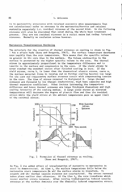
The p r i n c i p l e f o r t h e c r e a t i o n of thermal s t r e s s e s on c o o l i n g i s shown i n F i g . 1 f o r a s imple body (Rose and Hougardy, 1967). The s u r f a c e t e n p e r a t u r e decreases more r a p i d l y than t h e c o r e t empera tu re . Th is means t h a t t h e s p e c i f i c volume i s g r e a t e r i n t h e c o r e than i n t h e s u r f a c e . The volume c o n t r a c t i o n i n t h e
(
s u r f a c e i s prevented by t h e h igher s p e c i f i c volume i n t h e core . The thermal s t r e s s i s approximately p r o p o r t i o n a l t o t h e temperature d i f f e r e n c e and i s t e n s i l e i n t h e s u r f a c e and compressive i n t h e core . I f t h e y i e l d s t r e s s i s never reached t h e r e s i d u a l s t r e s s a f t e r f i n i s h e d c o o l i n g i s ze ro . I f t h e y i e l d s t r e s s , cu rve b , i s lower than t h e t h e o r e t i c a l e l a s t i c s t r e s s , cu rve a , the s u r f a c e m a t e r i a l f lows i n t e n s i o n and on f u r t h e r coo l ing becomes too l a r g e f o r t h e c o r e and compressive s u r f a c e s t r e s s e s r e s u l t wi th compensating t e n s i o n i n the core . The time of s t r e s s r e v e r s a l i s des igna ted U. Large thermal s t r e s s e s a r e favoured by low thermal c o n d u c t i v i t y , h igh h e a t c a p a c i t y and h igh thermal expansion c o e f f i c i e n t . Other f a c t o r s i n c r e a s i n g t h e t empera tu re d i f f e r e n c e and hence thermal s t r e s s e s a r e l a r g e t h i c k n e s s dimensions and h igh coo l ing i n t e n s i t y of t h e coo l ing medium. A l a r g e y i e l d s t r e s s a t e l e v a t e d t empera tu res w i l l d e c r e a s e t h e degree of p l a s t i c f low and t h u s t h e r e s i d u a l s t r e s s whi le t h e y i e l d s t r e s s a t t h e ambient t empera tu re p u t s an upper l i m i t t o t h e r e s i d u a l s t r e s s .
Water Quenched 100-mm
Specimen
- 4100 i 1001 1000 Time , seconds
Fig . 1 Formation of thermal s t r e s s e s on coo l ing . (Rose and Hougardy, 1967).
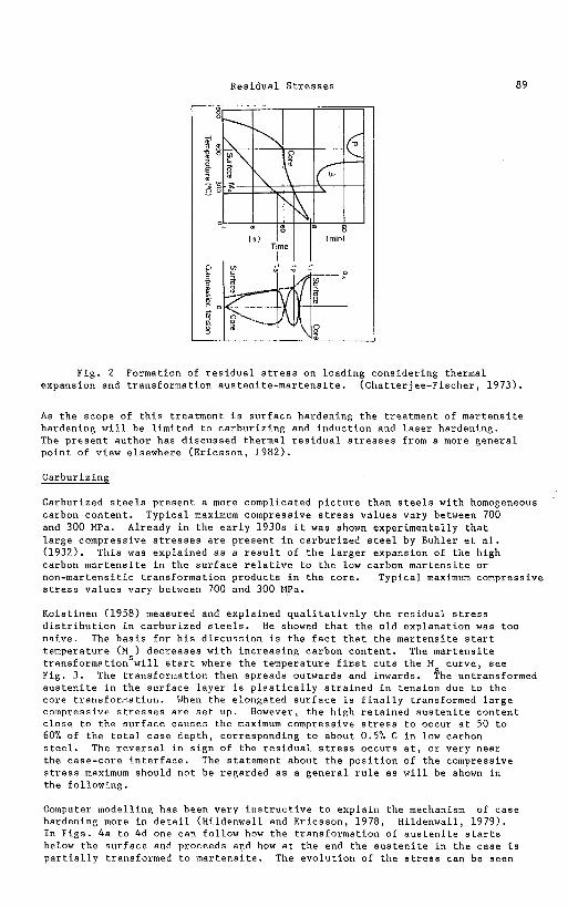
I n Fig. 2 t h e added e f f e c t of t r ans format ion of a u s t e n i t e t o m a r t e n s i t e i n s t e e l i s demonstrated. At time tl t h e s u r f a c e t empera tu re f a l l s below t h e m a r t e n s i t e s t a r t temperature Ms and t h e s u r f a c e s t a r t s t o t r ans form. I t expands and t h e thermal t e n s i l e a t r e s s e s a r e coun te rac ted . The s t r e s s r e v e r s a l t a k e s p l a c e e a r l i e r than o therwise . At t h e time t2 t h e c o r e t r ans forms which causes ano ther s t r e s s r e v e r s a l . Af te r c o o l i n g t rans format ion induced t e n s i l e s t r e s s e s a t t h e s u r f a c e dominate over t h e the rmal ly induced compressive s t r e s s .
Residual Stresses
Fig. 2 Form expansion and tran
ation of residual stress on loading considering thermal sformation austenite-martensite. (Chatterjee-Fischer, 1973).
As the scope of this treatment is surface hardening the treatment of martensite hardening will be limited to carburizing and induction and laser hardening. The present author has discussed thermal residual stresses from a more general point of view elsewhere (Ericsson, 1982).
Carburizine
Carburized steels present a more complicated picture than steels with homogeneous carbon content. Typical maximum compressive stress values vary between 700 and 300 MPa. Already in the early 1930s it was shown experimentally that large compressive stresses are present in carburized steel by Buhler et al. (1932). This was explained as a result of the larger expansion of the high carbon martensite in the surface relative to the low carbon martensite or non-martensitic transformation products in the core. Typical maximum compressive stress values vary between 700 and 300 MPa.
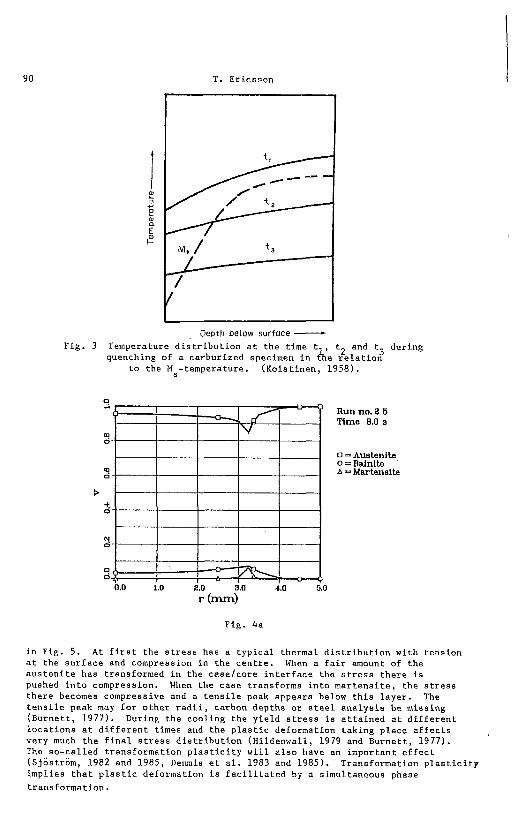
Koistinen (1958) measured and explained qualitatively the residual stress distribution in carburized steels. He showed that the old explanation was too naive. The basis for his discussion is the fact that the martensite start temperature (M ) decreases with increasing carbon content. The martensite transformationswill start where the temperature first cuts the M curve, see Fig. 3. The transformation then spreads outwards and inwards. ?he untransformed austenite in the surface layer is plastically strained in tension due to the core transformation. When the elongated surface is finally transformed large compressive stresses are set up. However, the high retained austenite content close to the surface causes the maximum compressive stress to occur at 50 to 60% of the total case depth, corresponding to about 0.5% C in low carbon steel. The reversal in sign of the residual stress occurs at, or very near the case-core interface. The statement about the position of the compressive stress maximum should not be regarded as a general rule as will be shown in the following.
Computer modelling has been very instructive to explain the mechanism of case hardening more in detail (Hildenwall and Ericsson, 1978, Hildenwall, 1979). In Figs. 4a to 4d one can follow how the transformation of austenite starts below the surface and proceeds and how at the end the austenite in the case is partially transformed to martensite. The evolution of the stress can be Been
T. Ericsson
Depth below surface - Fig. 3 Temperature distribution at the time t t and t3 during 2 quenching of a carburized specimen in &e relation
to the M -temperature. (Koistinen, 1958).
Run no. 2 5 Time 8.0 s
0 = Austenib 0 = Bainlte A = Martensite
Fig. 4a
in Fig. 5. At first the stress has a typical thermal distribution with tension at the surface and compression in the centre. When a fair amount of the austenite has transformed in the case/core interface the stress there is pushed into compression. When the case transforms into martensite, the stress there becomes compressive and a tensile peak appears below this layer. The tensile peak may for other radii, carbon depths or steel analysis be missing (Burnett, 1977). During the cooling the yield stress is attained at different locations at different times and the plastic deformation taking place affects very much the final stress distribution (Hildenwall, 1979 and Burnett, 1977). The so-called transformation plasticity will also have an important effect (Sjostrom, 1982 and 1985, Denmis et al. 1983 and 1985). Transformation plasticity implies that plastic deformation is facilitated by a simultaneous phase transformation.
Res idua l S t r e s s e s
0 i Run no. 2 5
Time 10.1 s
0 = Austenlte 0 = Balnite
2 A = Martenslte
k- t 0
2 0.0 1.0 2.0 3.0 4.0 5.0
r (mm)
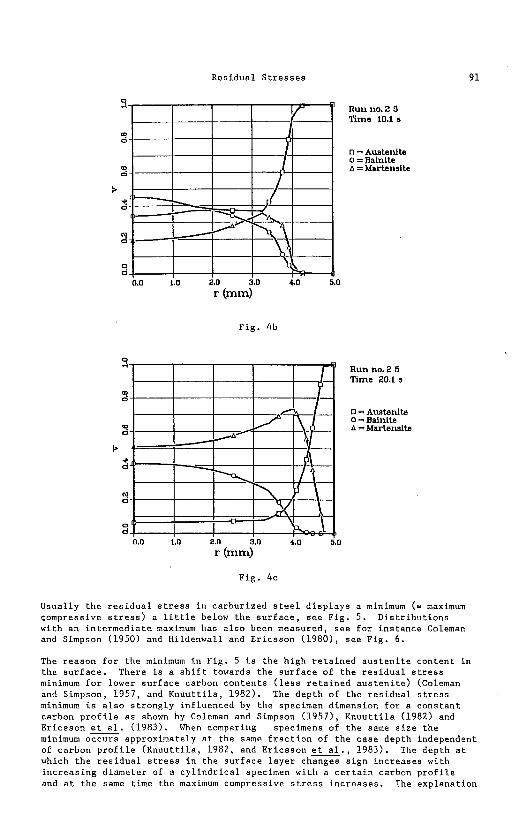
Fig . 4b
Run no. 2 5 Time 20.1 s
0 = Austenite 0 = Bainlte A = Martensite
k-
0.0 1.0 2.0 3.0 4.0 5.0
r (mm)
F i g . 4c
Usual ly t h e r e s i d u a l s t r e s s i n ca rbur ized s t e e l d i s p l a y s a minimum (= maximum compressive s t r e s s ) a l i t t l e below t h e s u r f a c e , s e e Fig. 5. D i s t r i b u t i o n s with an i n t e r m e d i a t e maximum has a l s o been measured, s e e f o r i n s t a n c e Coleman and Simpson (1950) and Hildenwall and Er icsson (1980) , s e e F ig . 6 .
The reason f o r t h e minimum i n F i g . 5 i s t h e h igh r e t a i n e d a u s t e n i t e con ten t i n the s u r f a c e . There i s a s h i f t towards t h e s u r f a c e of t h e r e s i d u a l s t r e s s minimum f o r lower s u r f a c e carbon c o n t e n t s ( l e s s r e t a i n e d a u s t e n i t e ) (Coleman and Simpson, 1957, and K n u u t t i l a , 1982). The dep th of t h e r e s i d u a l s t r e s s minimum is a l s o s t r o n g l y in f luenced by t h e specimen dimension f o r a c o n s t a n t carbon p r o f i l e a s shown by Coleman and Simpson (1957) , K n u u t t i l a (1982) and Er icsson e. (1983). When comparing specimens of t h e same s i z e t h e minimum occurs approximately a t t h e same f r a c t i o n of t h e c a s e depth independent of carbon p r o f i l e ( K n u u t t i l a , 1982, and E r i c s s o n e., 1983). The dep th a t which t h e r e s i d u a l s t r e s s i n t h e s u r f a c e l a y e r changes s i g n i n c r e a s e s with i n c r e a s i n g d iamete r of a c y l i n d r i c a l specimen w i t h a c e r t a i n carbon p r o f i l e and a t t h e same time t h e maximum compressive s t r e s s i n c r e a s e s . The exp lana t ion
T. Er icsson
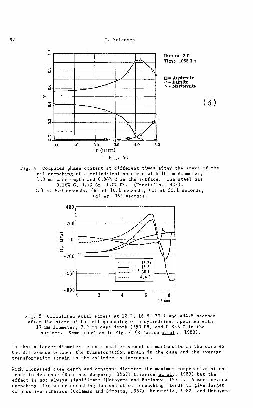
R u n no. 2 5 Time 1065.3 s
= Ausbnite 0 = Bainite A = Martensite
Fig. 4 Computed phase c o n t e n t a t d i f f e r e n t t imes a f t e r t h e s t a r t of t h e o i l quenching of a c y l i n d r i c a l specimen wi th 1 0 mm d i a m e t e r , 1 .0 mm c a s e dep th and 0.84% C i n t h e s u r f a c e . The s t e e l has
0.16% C, 0.7% Cr, 1.0% N i . ( K n u u t t i l a , 1982). ( a ) a t 8.0 seconds, ( b ) a t 10.1 seconds, ( c ) a t 20.1 seconds,
(d ) a t 1065 seconds.
Fig. 5 C a l c u l a t e d a x i a l s t r e s s a t 12 .2 , 16.8, 30.1 and 434.8 seconds a f t e r t h e s t a r t of t h e o i l quenching of a c y l i n d r i c a l specimen wi th
1 7 mm d i a m e t e r , 0 .9 mm c a s e depth (550 HV) and 0.85% C i n t h e s u r f a c e . Same s t e e l a s i n F ig . 4 ( E r i c s s o n e t . , 1983) .
i s t h a t a l a r g e r d iamete r means a smal le r amount of m a r t e n s i t e i n t h e c o r e so t h e d i f f e r e n c e between the t r ans format ion s t r a i n i n t h e c a s e and t h e average t rans format ion s t r a i n i n t h e c y l i n d e r i s inc reased .
With inc reased c a s e depth and c o n s t a n t diameter t h e maximum compressive s t r e s s tends t o d e c r e a s e ( ~ o s e and Hougardy, 1967) Er icsson u., 1983) b u t t h e e f f e c t i s n o t always s i g n i f i c a n t (Motoyama and Horisawa, 1971). A more severe quenching l i k e wa te r quenching i n s t e a d of o i l quenching, t ends t o g i v e l a r g e r compressive s t r e s s e s (Coleman and Simpson, 1957) , K n u u t t i l a , 1982, and Motoyama
Res idua l S t r e s s e s 93
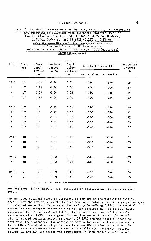
TABLE - 1 Res idua l S t r e s s e s Measured by X-ray D i f f r a c t i o n i n Mar tens i t e and A u s t e n i t e i n Cyl inders wi th d i f f e r e n t Diameters made of Swedish Standard S t e e l SS 2511 (0.16% C, 0.8% Mn, 0.7% Cr,
1.0% N i , 0.06% Mo) and SS 2523 (0.15% C, 0.9% Mn, 1.0% Cr, 1.1% N i , 0.1% Mo). R e l a t i v e Mean E r r o r
i n Res idua l S t r e s s < 10% ( m a r t e n s i t e ) R e l a t i v e Mean E r r o r i n Res idua l S t r e s s < 20% ( a u s t e n i t e )
( K n u u t t i l a , 1982)
S t e e l Diam. Case Surface Res idua l S t r e s s MPa
mm dep th carbon con ten t 550 HC con t . s u r f a c e %
mm % mm m a r t e n s i t e a u s t e n i t e
and Horisawa, 1971) which i s a l s o supported by c a l c u l a t i o n s ( E r i c s s o n e t a l . , 1983).
The measured r e s i d u a l s t r e s s e s d i scussed s o f a r a r e i n t h e m a r t e n s i t e l b a i n i t e phase. But t h e s t r u c t u r e i n t h e h igh carbon c a s e c o n t a i n s f a i r l y l a r g e percen tages of r e t a i n e d a u s t e n i t e . I n an e x t e n s i v e work by Beumelburg (1974) t h e r e s i d u a l s t r e s s and t h e r e t a i n e d a u s t e n i t e con ten t were measured i n 4 d i f f e r e n t s t e e l s ca rbur ized t o between 0.45 and 1.20% C i n t h e s u r f a c e . Most of t h e s t e e l s were annealed a t 170•‹C. As a g e n e r a l t r e n d t h e a u s t e n i t e s t r e s s decreased wi th inc reased r e t a i n e d a u s t e n i t e c o n t e n t (9-65%) and was t e n s i l e except f o r more than 40% a u s t e n i t e . The m a r t e n s i t e s t r e s s inc reased and was compressive below 10% and most o f t e n s l i g h t l y t e n s i l e above 10% r e t a i n e d a u s t e n i t e . I n another f a i r l y e x t e n s i v e s tudy by K n u u t t i l a (1982) wi th a u s t e n i t e c o n t e n t s between 1 5 and 32% t h e s t r e s s was compressive i n both phases excep t i n one
T. Ericsson
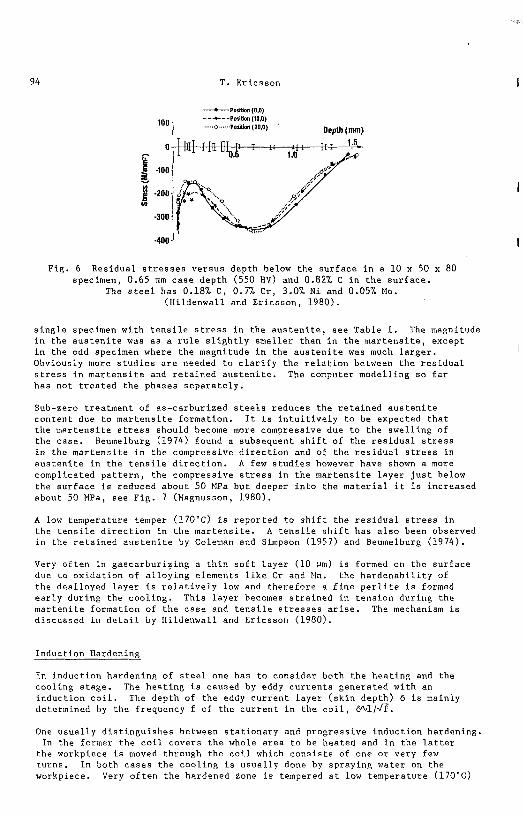
Fig. 6 Residual stresses versus depth below the surface in a 10 x 50 x 80 specimen, 0.65 mm case depth (550 HV) and 0.82% C in the surface.
The steel has 0.18% C, 0.7% Cr, 3.0% Ni and 0.05% No. (Hildenwall and Ericsson, 1980).
single specimen with tensile stress in the austenite, see Table 1. The magnitude in the austenite was as a rule slightly smaller than in the martensite, except in the odd specimen where the magnitude in the austenite was much larger. I Obviously more studies are needed to clarify the relation between the residual stress in martensite and retained austenite. The computer modelling so far has not treated the phases separately.
Sub-zero treatment of as-carburized steels reduces the retained austenite content due to martensite formation. It is intuitively to be expected that the martensite stress should become more compressive due to the swelling of the case. Beumelburg (1974) found a subsequent shift of the residual stress in the martensite in the compressive direction and of the residual stress in austenite in the tensile direction. A few studies however have shown a more complicated pattern, the compressive stress in the martensite layer just below the surface is reduced about 50 MPa but deeper into the material it is increased about 50 MPa, see Fig. 7 (Magnusson, 1980).
A low temperature temper (170•‹C) is reported to shift the residual stress in the tensile direction in the martensite. A tensile shift has also been observed in the retained austenite by Coleman and Simpson (1957) and Beumelburg (1974).
Very often in gascarburizing a thin soft layer (10 wm) is formed on the surface due to oxidation of alloying elements like Cr and Mn. the hardenability of the dealloyed layer is relatively low and therefore a fine perlite is formed early during the cooling. This layer becomes strained in tension during the martenite formation of the case and tensile stresses arise. The mechanism is discussed in detail by Hildenwall and Ericsson (1980).
Induction Hardening
In induction hardening of steel one has to consider both the heating and the cooling stage. The heating is caused by eddy currents generated with an induction coil. The depth of the eddy current layer (skin depth) 6 is mainly determined by the frequency f of the current in the coil, 6"Jl/G.
One usually distinguishes between stationary and progressive induction hardening. In the former the coil covers the whole area to be heated and in the latter the workpiece is moved through the coil which consists of one or very few turns. In both cases the cooling is usually done by spraying water on the workpiece. Very often the hardened zone is tempered at low temperature (170•‹C)
Res idua l S t r e s s e s
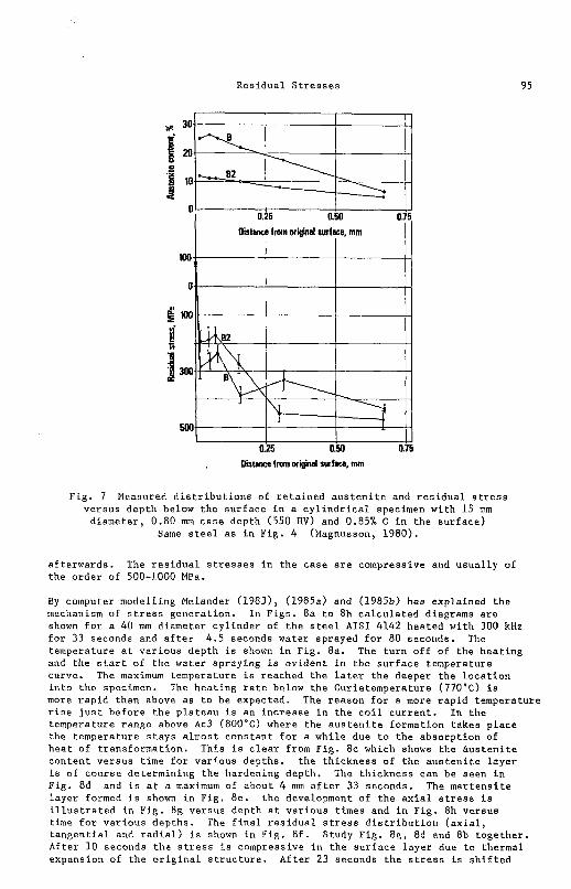
F ig . 7 Measured d i s t r i b u t i o n s of r e t a i n e d a u s t e n i t e and r e s i d u a l s t r e s s v e r s u s dep th below t h e s u r f a c e i n a c y l i n d r i c a l specimen wi th 1 5 mm
d iamete r , 0.80 mm c a s e depth (550 HV) and 0.85% C i n t h e s u r f a c e ) Same s t e e l a s i n F ig . 4 (Magnusson, 1980).
a f t e r w a r d s . The r e s i d u a l s t r e s s e s i n t h e c a s e a r e compressive and u s u a l l y of t h e o r d e r of 500-1000 MPa.
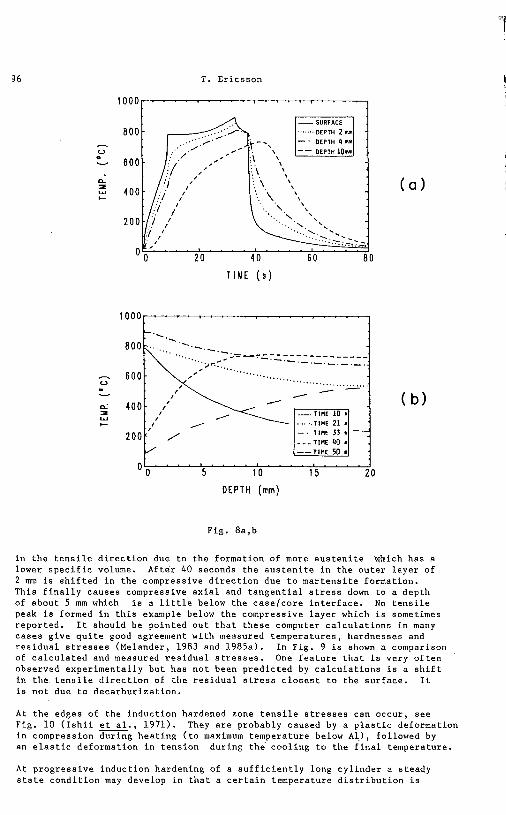
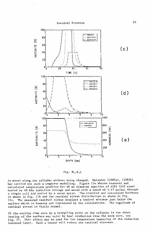
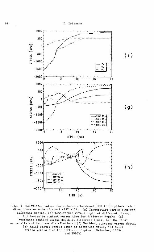
By computer model l ing Melander (1983), (1985a) and (1985b) has exp la ined t h e mechanism of s t r e s s genera t ion . I n F igs . 8a t o 8h c a l c u l a t e d diagrams a r e shown f o r a 40 mm diameter c y l i n d e r of t h e s t e e l AISI 4142 hea ted wi th 300 kHz f o r 33 seconds and a f t e r 4.5 seconds water sprayed f o r 80 seconds. The temperature a t v a r i o u s dep th i s shown i n Fig. 8a . The t u r n o f f of t h e h e a t i n g and t h e s t a r t of t h e wa te r sp ray ing i s e v i d e n t i n t h e s u r f a c e t empera tu re curve. The maximum temperature i s reached t h e l a t e r t h e deeper t h e l o c a t i o n i n t o t h e specimen. The h e a t i n g r a t e below t h e Cur ie tempera tu re (770•‹C) i s more r a p i d than above a s t o be expected. The reason f o r a more r a p i d temperature r i s e j u s t b e f o r e t h e p l a t e a u i s an i n c r e a s e i n t h e c o i l c u r r e n t . I n t h e temperature range above Ac3 (800'C) where t h e a u s t e n i t e fo rmat ion t a k e s p l a c e t h e t empera tu re s t a y s almost c o n s t a n t f o r a whi le due t o t h e a b s o r p t i o n of h e a t of t r ans format ion . Th is i s c l e a r from Fig . 8c which shows t h e a u s t e n i t e c o n t e n t v e r s u s t ime f o r va r ious dep ths . t h e t h i c k n e s s of t h e a u s t e n i t e l a y e r i s of c o u r s e de te rmin ing t h e hardening dep th . The t h i c k n e s s can be seen i n Fig. 8d and i s a t a maximum of about 4 mm a f t e r 33 seconds. The m a r t e n s i t e l a y e r formed i s shown i n F i g . 8e . t h e development of t h e a x i a l s t r e s s i s i l l u s t r a t e d i n F i g . 8g v e r s u s depth a t v a r i o u s t imes and i n F ig . 8h v e r s u s time f o r v a r i o u s dep ths . The f i n a l r e s i d u a l s t r e s s d i s t r i b u t i o n ( a x i a l , t a n g e n t i a l and r a d i a l ) i s shown i n F ig . 8 f . Study Fig. Bg, 8d and 8b t o g e t h e r . A f t e r 1 0 seconds t h e s t r e s s i s compressive i n t h e s u r f a c e l a y e r due t o thermal expansion of t h e o r i g i n a l s t r u c t u r e . A f t e r 23 seconds t h e s t r e s s i s s h i f t e d
T. Ericsson
T I M E ( s )
0 ~ 0 " ' " ' ~ ~ ~ " ' ~ " " ~ ~ 1 5 1 0 1 5 2 0
D E P T H (mm)
Fig. 8a,b
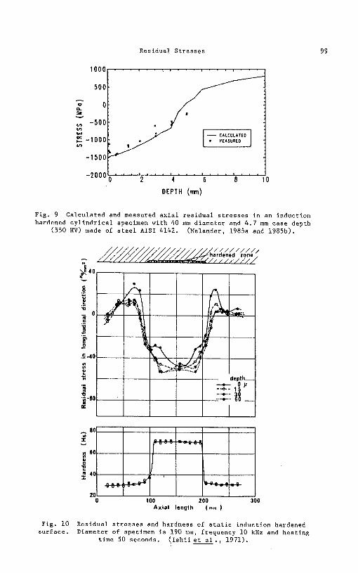
in the tensile direction due to the formation of more austenite which has a lower specific volume. After 40 seconds the austenite in the outer layer of 2 mm is shifted in the compressive direction due to martensite formation. This finally causes compressive axial and tangential stress down to a depth of about 5 mm which is a little below the caselcore interface. No tensile peak is formed in this example below the compressive layer which is sometimes reported. It should be pointed out that these computer calculations in many cases give quite good agreement with measured temperatures, hardnesses and residual stresses (Melander, 1983 and 1985a). In Fig. 9 is shown a comparison of calculated and measured residual stresses. One feature that is very often observed experimentally but has not been predicted by calculations is a shift in the tensile direction of the residual stress closest to the surface. It is not due to decarburization.
At the edges of the induction hardened zone tensile stresses can occur, see Fig. 10 (Ishii u., 1971). They are probably caused by a plastic deformation in compression during heating (to maximum temperature below All, followed by an elastic deformation in tension during the cooling to the final temperature.
At progressive induction hardening of a sufficiently long cylinder a steady state condition may develop in that a certain temperature distribution is
Residual S t r e s s e s
T I M E ( s )
DEPTH (mn)
Fig. 8 c , d , e
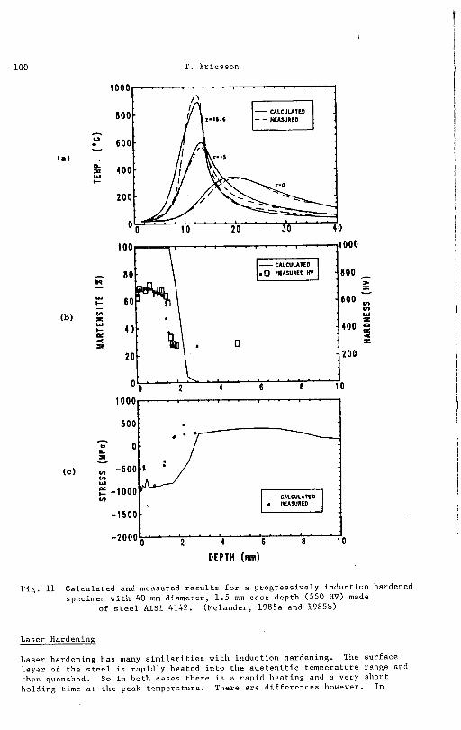
i s moved a long t h e c y l i n d e r wi thou t being changed. Melander (1985a) , (1985b) has c a r r i e d o u t such a computer model l ing. F i g u r e l l a shuows measured and c a l c u l a t e d t empera tu re p r o f i l e s f o r 40 mn, d iamete r specimen of AISI 4142 s t e e l heated by 40 kHz i n d u c t i o n v o l t a g e and moved wi th a speed of 3 .47 mmlsec through a s i n g l e c o i l and cooled by a water sp ray . The measured and c a l c u l a t e d hardness i s shown i n F i g . l l b and t h e r e s i d u a l s t r e s s d i s t r i b u t i o n i s shown i n Fig. l l c . The measured r e s i d u a l s t r e s s d i s p l a y s a t y p i c a l minimum j u s t below t h e s u r f a c e which i s however n o t reproduced by t h e c a l c u l a t i o n s . The magnitude of r e s i d u a l s t r e s s i s f a i r l y normal.
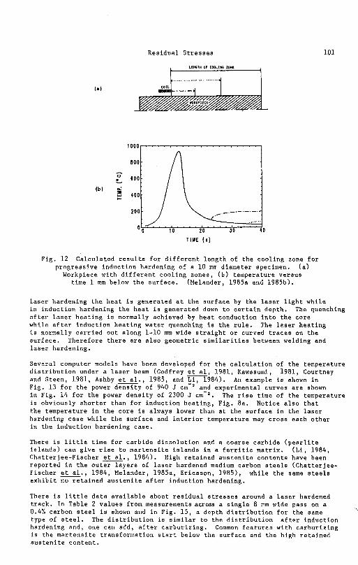
I f t h e c o o l i n g time seen by a t r a v e l l i n g p o i n t on t h e c y l i n d e r i s too s h o r t h e a t i n g of t h e s u r f a c e may occur by h e a t conduct ion from t h e warm c o r e , s e e F ig . 1 2 . T h i s e f f e c t may be used f o r low temperature tempering of t h e induc t ion hardened l a y e r . Such a temper w i l l reduce t h e r e s i d u a l s t r e s s e s .
T. Er icsson
F i g . 8 C a l c u l a t e d v a l u e s f o r induc t ion hardened (300 kHz) c y l i n d e r wi th 40 mm d iamete r made of s t e e l AISI 4142. ( a ) Temperature v e r s u s time f o r
d i f f e r e n t d e p t h s , ( b ) Temperature v e r s u s depth a t d i f f e r e n t t imes , (c) A u s t e n i t e con ten t v e r s u s time f o r d i f f e r e n t d e p t h s , ( d )
A u s t e n i t e c o n t e n t v e r s u s depth a t d i f f e r e n t t imes , ( e ) The f i n a l m a r t e n s i t e and hardness d i s t r i b u t i o n s , ( f ) Res idua l s t r e s s e s v e r s u s dep th ,
( g ) Axia l s t r e s s ve rsus depth a t d i f f e r e n t t i m e s , ( h ) Axia l s t r e s s v e r s u s time f o r d i f f e r e n t d e p t h s , (Melander, 1985a
and 1985b)
Residual Stresses
D E P T H (inn)
Fig . 9 Calculated and measured a x i a l residual s t r e s s e s i n an induction hardened c y l i n d r i c a l specimen with 40 mm diameter and 4 . 7 mm case depth
(550 HV) made of s t e e l AISI 4142. (Melander, 1985a and 1985b).
80 2 -
60 U
E 40
20 0 100 200 300
Ax ia l length ( m m )
F i g . 10 Residual s t r e s s e s and hardness of s t a t i c induction hardened surface. Diameter of specimen i s 190 mm, frequency 10 kHz and heating
time 50 seconds. ( I s h i i e . , 1971).
T. E r i c s s o n
0
T. E r i c s s o n
F i g . 11 C a l c u l a t e d and measured r e s u l t s f o r a p r o g r e s s i v e l y i n d u c t i o n hardened specimen w i t h 40 mm d i a m e t e r , 1 . 5 mm c a s e d e p t h (550 HV) made
o f s t e e l A I S I 4142. (Melander , 1985a and 1985b)
L a s e r Hardening
L a s e r h a r d e n i n g h a s many s i m i l a r i t i e s w i t h i n d u c t i o n ha rden ing . The s u r f a c e l a y e r of t h e s t e e l i s r a p i d l y h e a t e d i n t o t h e a u s t e n i t i c t e m p e r a t u r e r a n g e and then quenched. So i n bo th c a s e s t h e r e i s a r a p i d h e a t i n g and a ve ry s h o r t h o l d i n g t ime a t t h e peak t empera tu re . The re a r e d i f f e r e n c e s however. I n
Res idua l S t r e s s e s
Fig. 1 2 Ca lcu la ted r e s u l t s f o r d i f f e r e n t l e n g t h of t h e coo l ing zone f o r p r o g r e s s i v e i n d u c t i o n hardening of a 1 0 mn diameter specimen. ( a )
Workpiece wi th d i f f e r e n t c o o l i n g zones , ( b ) temperature v e r s u s time 1 mm below t h e s u r f a c e . (Melander, 1985a and 1985b).
l a s e r hardening t h e h e a t i s genera ted a t t h e s u r f a c e by t h e l a s e r l i g h t whi le i n i n d u c t i o n hardening t h e h e a t i s genera ted down t o c e r t a i n dep th . The quenching a f t e r l a s e r h e a t i n g i s normally achieved by h e a t conduct ion i n t o t h e c o r e whi le a f t e r i n d u c t i o n h e a t i n g wate r quenching i s t h e r u l e . The l a s e r h e a t i n g i s normally c a r r i e d o u t a long 1-10 mm wide s t r a i g h t o r curved t r a c e s on t h e s u r f a c e . There fore t h e r e a r e a l s o geometr ic s i m i l a r i t i e s between welding and l a s e r ha rden ing .
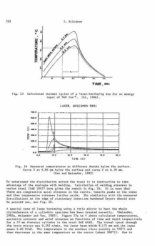
Severa l computer models have been developed f o r t h e c a l c u l a t i o n of t h e temperature d i s t r i b u t i o n under a l a s e r beam (Godfrey a, 1981, Kawasumi, 1981, Courtney and S teen , 1981, Ashby u., 1985, end L i , 1984). An example i s shown i n F i g . 1 3 f o r t h e power d e n s i t y of 940 J and exper imenta l curves a r e shown i n Fig. 1 4 f o r t h e power d e n s i t y of 2300 J cm-'. The r i s e time of t h e temperature i s obv ious ly s h o r t e r than f o r i n d u c t i o n h e a t i n g , Fig. 8a . Notice a l s o t h a t t h e temperature i n t h e c o r e i s always lower than a t t h e s u r f a c e i n t h e l a s e r hardening c a s e w h i l e t h e s u r f a c e and i n t e r i o r temperature may c r o s s each o t h e r i n t h e i n d u c t i o n harden ing case .
There i s l i t t l e time f o r c a r b i d e d i s s o l u t i o n and a c o a r s e c a r b i d e ( p e a r l i t e i s l a n d s ) can g i v e r i s e t o m a r t e n s i t e i s l a n d s i n a f e r r i t i c mat r ix . ( L i , 1984, Cha t te r j ee -F i scher G., 1984). High r e t a i n e d a u s t e n i t e c o n t e n t s have been r e p o r t e d i n t h e o u t e r l a y e r s of l a s e r hardened medium carbon s t e e l s ( C h a t t e r j e e - F i scher u., 1984, Melander, 1985a, E r i c s s o n , 1985) , whi le t h e same s t e e l s e x h i b i t no r e t a i n e d a u s t e n i t e a f t e r i n d u c t i o n hardening.
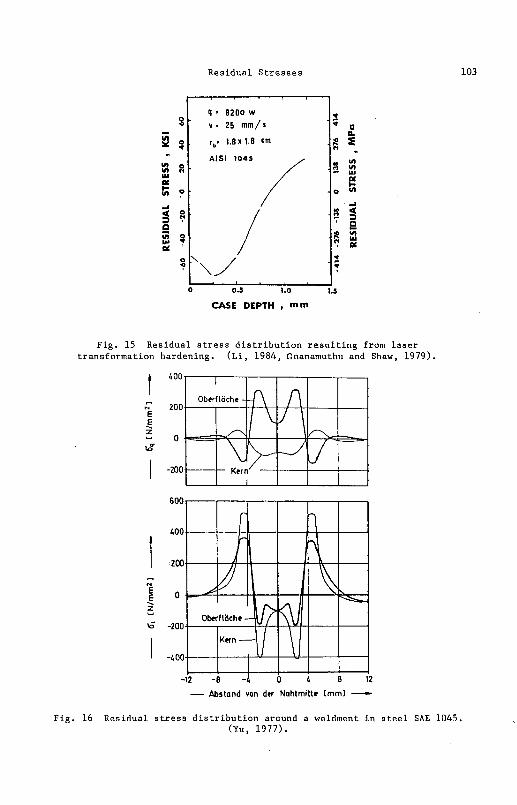
There i s l i t t l e d a t a a v a i l a b l e about r e s i d u a l s t r e s s e s around a l a s e r hardened t r a c k . I n Table 2 v a l u e s from measurements across a s i n g l e 8 mm wide pass on a 0.4% carbon s t e e l i s shown and i n Fig. 1 5 , a depth d i s t r i b u t i o n f o r t h e same type of s t e e l . The d i s t r i b u t i o n i s s i m i l a r t o t h e d i s t r i b u t i o n a f t e r i n d u c t i o n hardening and, one can add , a f t e r c a r b u r i z i n g . Common f e a t u r e s wi th c a r b u r i z i n g i s t h e m a r t e n s i t e t r ans format ion s t a r t below t h e s u r f a c e and t h e high r e t a i n e d a u s t e n i t e c o n t e n t .
T. E r i c s s o n
Fig. 1 3 Ca lcu la ted thermal c y c l e s of a l a se r -harden ing r u n f o r an energy i n p u t of 940 ( L i , 1984).
LASER, SPECIMEN 583 1
700.8
100.8
E49.8
CI
4a0.8
380.8 W I-
288.0
180.8
8.8
0.0 18.8 20.9 38.1 48.8 68.0
TIME C S )
Fig. 1 4 Measured temperatures a t d i f f e r e n t dep ths below t h e s u r f a c e . Curve 3 a t 0.86 mm below t h e s u r f a c e and curve 2 a t 4.70 mm.
(Yao and Melander, 1983)
To unders tand t h e d i s t r i b u t i o n a c r o s s t h e t r a c e it i s i n s t r u c t i v e t o t a k e advantage of t h e analogue w i t h welding. C a l c u l a t i o n of welding s t r e s s e s i n carbon s t e e l (SAE 1045) have given t h e r e s u l t i n Fig. 16. It i s seen t h a t t h e r e a r e compressive a x i a l s t r e s s e s i n t h e c e n t r e , t e n s i l e peaks a t t h e s i d e s and then compressive s t r e s s e s f u r t h e r a s i d e . The s i m i l a r i t y wi th t h e measured d i s t r i b u t i o n s a t t h e edge of s t a t i o n a r y i n d u c t i o n hardened l a y e r s should a l s o be po in ted o u t , s e e F ig . 10.
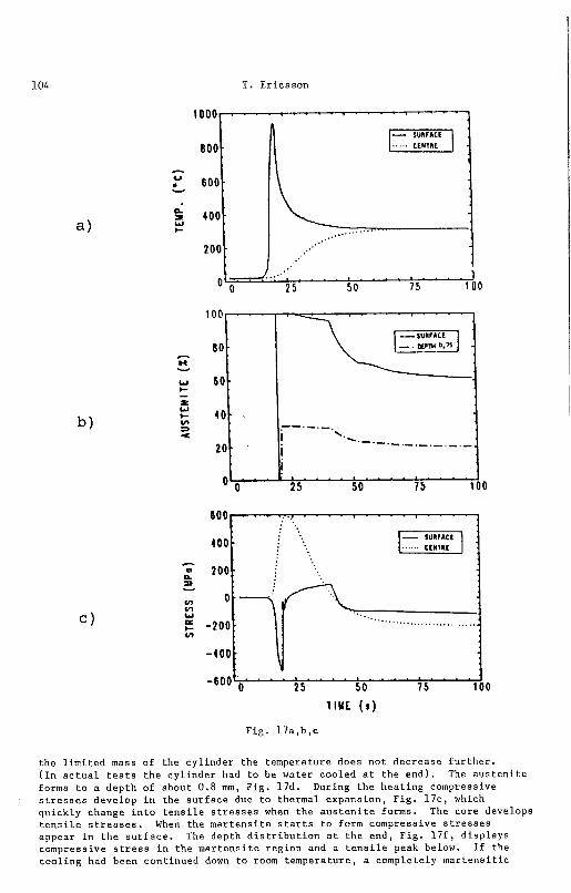
A s p e c i a l c a s e of l a s e r hardening using a t o r i c m i r r o r t o h e a t t h e whole c i rcumference of a c y l i n d r i c specimen has been t r e a t e d r e c e n t l y . (Melander, 1985a, Melander and Yao, 1985). F igure 17a t o f shows c a l c u l a t e d t empera tu res , a u s e e n i t e c o n t e n t s and a x i a l s t r e s s e s a s f u n c t i o n s of t ime and depth r e s p e c t i v e l y f o r a 57 mm d iamete r c y l i n d e r i n t h e s t e e l SAE 4142. The t r a v e l speed through t h e t o r i c m i r r o r was 0.152 mlmin, t h e l a s e r beam wid th 8.175 mm and t h e i n p u t power 6.60 Wlm2. The temperature i n t h e s u r f a c e r i s e s qu ick ly t o 950•‹C and then d e c r e a s e s t o t h e same temperature a s t h e c e n t r e (about 300•‹C). Due t o
Residual S t r e s s e s
F ig . 15 Residual s t r e s s d i s t r i b u t i o n r e s u l t i n g from l a s e r transformation hardening. ( L i , 1984, Gnanamuthu and Shaw, 1979) .
- &stand von der Nahlmille tmml - Fig . 16 Residual s t r e s s d i s t r i b u t i o n around a weldment i n s t e e l SAE 1045.
(Yu, 1977) .
T. Er icsson
T I M E (s)
Fig. 1 7 a , b , c
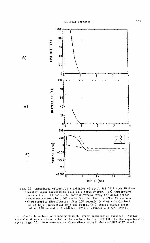
t h e l i m i t e d mass of the c y l i n d e r t h e temperature does n o t decrease f u r t h e r . ( I n a c t u a l t e s t s t h e c y l i n d e r had t o be water cooled a t t h e end) . The a u s t e n i t e forms t o a dep th of about 0.8 m m , Fig. 17d. During t h e h e a t i n g compressive s t r e s s e s develop i n the s u r f a c e due t o thermal expans ion , F i g . 1 7 c , which qu ick ly change i n t o t e n s i l e s t r e s s e s when t h e a u s t e n i t e forms. The core develops t e n s i l e s t r e s s e s . When t h e m a r t e n s i t e s t a r t s t o form compressive s t r e s s e s appear i n t h e s u r f a c e . The depth d i s t r i b u t i o n a t t h e end , F ig . 1 7 f , d i s p l a y s compressive s t r e s s i n t h e m a r t e n s i t e r e g i o n and a t e n s i l e peak below. I f t h e c o o l i n g had been cont inued down t o room tempera tu re , a completely m a r t e n s i t i c
Res idua l S t r e s s e s
D E P T H (mn)
Fig . 1 7 C a l c u l a t e d v a l u e s f o r a c y l i n d e r of s t e e l SAE 4142 wi th 28.6 mm d iamete r l a s e r hardened by h e l p of a t o r i c m i r r o r . ( a ) temperature
v e r s u s t ime , ( b ) a u s t e n i t e c o n t e n t v e r s u s t ime , ( c ) a x i a l s t r e s s component v e r s u s t ime , ( d ) a u s t e n i t e d i s t r i b u t i o n a f t e r 24 seconds ( e l m a r t e n s i t e d i s t r i b u t i o n a f t e r 100 seconds (end of c a l c u l a t i o n ) ,
a x i a l (o ) , t a n g e n t i a l (o ) and r a d i a l (o ) s t r e s s v e r s u s depth a f t e r 180 seconds. ( ~ e l g n d e r , 1985a, ~ e f a n d e r and Yao, 1985).
c a s e should have been ob ta ined wi th much l a r g e r compressive s t r e s s e s . Notice t h a t t h e s t r e s s minimum i s below t h e s u r f a c e i n F ig . 17f l i k e i n t h e experimental curve , Fig. 15 . Measurements on 15 mm diameter c y l i n d e r s of SAE 4142 s t e e l
106 T. Er icsson
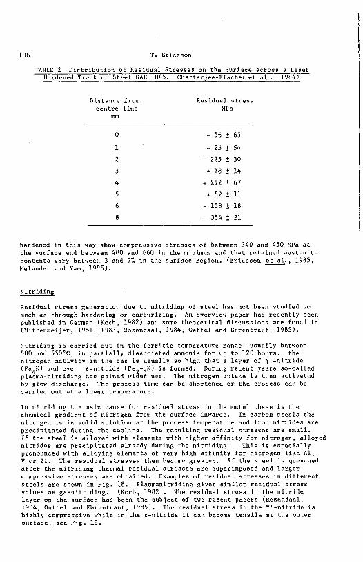
TABLE 2 D i s t r i b u t i o n of Res idua l S t r e s s e s on the Sur face a c r o s s a Laser Hardened Track on S t e e l SAE 1045. C h a t t e r j e e - F i s c h e r e t a l . , 1984')
Dis tance from c e n t r e l i n e
rnm
Residual s t r e s s MP a
hardened i n t h i s way show compressive s t r e s s e s of between 340 and 450 MPa a t t h e s u r f a c e and between 480 and 660 i n t h e minimum and t h a t r e t a i n e d a u s t e n i t e c o n t e n t s va ry between 3 and 7% i n t h e s u r f a c e reg ion . ( E r i c s s o n u., 1985, Melander and Yao, 1985) .
N i t r i d i n g
Res idua l s t r e s s g e n e r a t i o n due t o n i t r i d i n g of s t e e l has n o t been s t u d i e d so much a s through hardening o r c a r b u r i z i n g . An overview paper has r e c e n t l y been pub l i shed i n German (Koch, 1982) and some t h e o r e t i c a l d i s c u s s i o n s a r e found i n (Mi t t enmei je r , 1981, 1983, Rozendaal , 1984, O e t t e l and E h r e n t r a u t , 1985).
N i t r i d i n g i s c a r r i e d o u t i n t h e f e r r i t i c temperature range , u s u a l l y between 500 and 550•‹C, i n p a r t i a l l y d i s s o c i a t e d ammonia f o r up t o 120 hours . t h e n i t r o g e n a c t i v i t y i n t h e gas is u s u a l l y s o h igh t h a t a l a y e r of 7 ' - n i t r i d e ( F ~ ~ N ) and even € - n i t r i d e (Fe -3N) i s formed. During r e c e n t years s o - c a l l e d p lasma-n i t r id ing has gained wi3er use. The n i t r o g e n uptake i s then a c t i v a t e d by glow d i scharge . The p r o c e s s time can be shor tened o r t h e p rocess can be c a r r i e d o u t a t a lower t empera tu re .
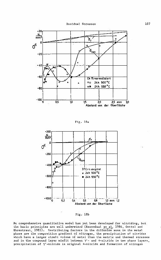
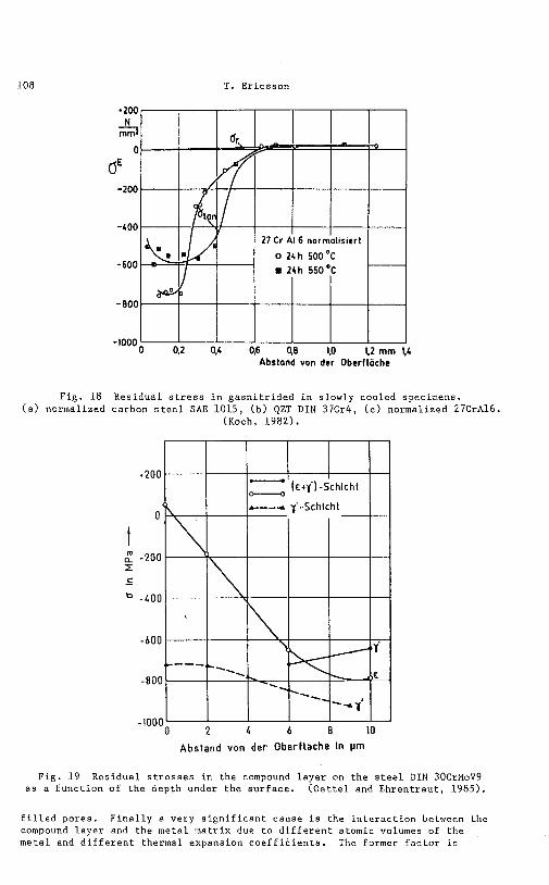
I n n i t r i d i n g t h e main cause f o r r e s i d u a l s t r e s s i n t h e meta l phase i s t h e chemical g r a d i e n t o f n i t r o g e n from t h e s u r f a c e inwards. I n carbon s t e e l s the n i t r o g e n i s i n s o l i d s o l u t i o n a t t h e p rocess temperature and i r o n n i t r i d e s a r e p r e c i p i t a t e d dur ing t h e c o o l i n g . The r e s u l t i n g r e s i d u a l s t r e s s e s a r e small . I f t h e s t e e l i s a l l o y e d wi th elements wi th h igher a f f i n i t y f o r n i t r o g e n , a l loyed n i t r i d e s a r e p r e c i p i t a t e d a l r e a d y dur ing t h e n i t r i d i n g . 'Chis i s e s p e c i a l l y pronounced w i t h a l l o y i n g elements of ve ry high a f f i n i t y f o r n i t r o g e n l i k e A l , V o r Ti . The r e s i d u a l s t r e s s e s then become g r e a t e r . I f t h e s t e e l i s quenched a f t e r t h e n i t r i d i n g thermal r e s i d u a l s t r e s s e s a r e superimposed and l a r g e r compressive s t r e s s e s a r e ob ta ined . Examples of r e s i d u a l s t r e s s e s i n d i f f e r e n t s t e e l s a r e shown i n F i g . 18. P lasmani t r id ing g ives s i m i l a r r e s i d u a l s t r e s s v a l u e s a s g a s n i t r i d i n g . (Koch, 1982). The r e s i d u a l s t r e s s i n t h e n i t r i d e l a y e r on t h e s u r f a c e has been t h e s u b j e c t of two r e c e n t papers (Rozendaal, 1984, O e t t e l and E h r e n t r a u t , 1985). The r e s i d u a l s t r e s s i n t h e 7 ' - n i t r i d e i s h igh ly compressive whi le i n t h e € - n i t r i d e it can become t e n s i l e a t t h e o u t e r s u r f a c e , s e e F ig . 19 .
Residual Stresses
.20 -CL rnrn 2
0
bE -20
-40
- 60
Fig. 18a
~ b s t o n d von der 0berf&he
Fig. 18b
No comprehensive quantitative model has yet been developed for nitriding, but the basic principles are well understood (Rozendaal Gal, 1984, Oettel and Ehrentraut, 1985). Contributing factors in the diffusion zone in the metal phase are the composition gradient of nitrogen, the precipitation of nitrides which have a larger atomic volume of metal than the matrix and thermal stresses and in the compound layer misfit between 7 ' - and €-nitride in two phase layers, precipitation of y'-nitride in original €-nitride and formation of nitrogen
T. Er icsson
F ig . 1 8 Res idua l s t r e s s i n g a s n i t r i d e d i n s lowly cooled specimens. ( a ) normalized carbon s t e e l SAE 1015, ( b ) QZT D I N 37Cr4, ( c ) normalized 27CrA16.
(Koch, 1982).
2 4 b 8 10
Abstand von der Ober f lache In urn
Fig . 19 Res idua l s t r e s s e s i n t h e compound l a y e r on t h e s t e e l D I N 30CrMoV9 a s a f u n c t i o n of t h e dep th under t h e s u r f a c e . ( O e t t e l and E h r e n t r a u t , 1985).
F i l l e d pores . F i n a l l y a very s i g n i f i c a n t cause i s t h e i n t e r a c t i o n between t h e compound l a y e r and t h e meta l m a t r i x due t o d i f f e r e n t atomic volumes of t h e meta l and d i f f e r e n t thermal expansion c o e f f i c i e n t s . The former f a c t o r i s
Res idua l S t r e s s e s 109
u s u a l l y expressed by h e l p of t h e Pi l l ing-Bedworth (PB) r a t i o which f o r pure i r o n n i t r i d e s a r e 1.16 ( y l / a ) and 1.15 ( € / a ) (Rozendaal s., 1984). The i n t e r a c t i o n should g i v e a t e n s i l e s t r e s s c o n t r i b u t i o n t o t h e meta l s u r f a c e zone and a s t r o n g compressive s t r e s s c o n t r i b u t i o n t o t h e compound l a y e r .
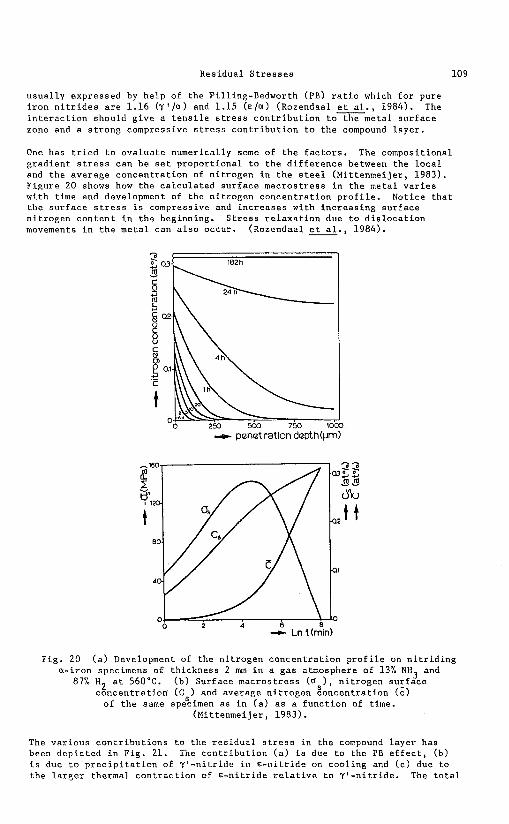
One has t r i e d t o e v a l u a t e numerical ly some of t h e f a c t o r s . The composi t ional g r a d i e n t s t r e s s can be s e t p r o p o r t i o n a l t o t h e d i f f e r e n c e between t h e l o c a l and t h e average c o n c e n t r a t i o n of n i t r o g e n i n t h e s t e e l (Mi t t enmei je r , 1983). F igure 20 shows how t h e c a l c u l a t e d s u r f a c e m a c r o s t r e s s i n t h e meta l v a r i e s wi th time and development of t h e n i t r o g e n c o n c e n t r a t i o n p r o f i l e . Notice t h a t t h e s u r f a c e s t r e s s i s compressive and i n c r e a s e s wi th i n c r e a s i n g s u r f a c e n i t r o g e n c o n t e n t i n t h e beginning. S t r e s s r e l a x a t i o n due t o d i s l o c a t i o n movements i n t h e m e t a l can a l s o occur . (Rozendaal Gal., 1984).
-t penetration depth(pn
Fig . 20 ( a ) Development of t h e n i t r o g e n c o n c e n t r a t i o n p r o f i l e on n i t r i d i n g a - i r o n specimens of t h i c k n e s s 2 mm i n a g a s atmosphere of 13% NH and 3
87% H2 a t 560•‹C. ( b ) Sur face macros t ress (0 ) , n i t r o g e n s u r f a c e c o n c e n t r a t i o e (C ) and average n i t r o g e n g o n c e n t r a t i o n ( c )
of t h e same spescimen a s i n ( a ) a s a f u n c t i o n of time. (Mi t t enmei je r , 1983).
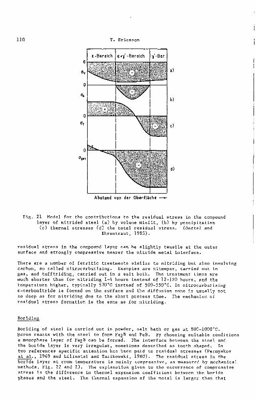
The v a r i o u s c o n t r i b u t i o n s t o t h e r e s i d u a l s t r e s s i n t h e compound l a y e r has been d e p i c t e d i n F ig . 21. The c o n t r i b u t i o n ( a ) i s due t o t h e PB e f f e c t , (b) i s due t o p r e c i p i t a t i o n of y r - n i t r i d e i n E - n i t r i d e on coo l ing and ( c ) due t o t h e l a r g e r the rmal c o n t r a c t i o n of E - n i t r i d e r e l a t i v e t o "( ' -ni t r ide. The t o t a l
T. Er icsson
, Abstand van der O b c r f k h e -
Fig . 21 Model f o r the c o n t r i b u t i o n s t o t h e r e s i d u a l s t r e s s i n t h e compound l a y e r of n i t r i d e d s t e e l ( a ) by volume m i s f i t , ( b ) by p r e c i p i t a t i o n
( c ) thermal s t r e s s e s ( d l t h e t o t a l r e s i d u a l s t r e s s . ( 0 e t t e l and E h r e n t r a u t , 1985).
r e s i d u a l s t r e s s i n t h e compound l a y e r can be s l i g h t l y t e n s i l e a t t h e o u t e r s u r f a c e and s t r o n g l y compressive n e a r e r t h e n i t r i d e meta l i n t e r f a c e .
There a r e a number of f e r r i t i c t r ea tments s i m i l a r t o n i t r i d i n g b u t a l s o invo lv ing carbon, s o c a l l e d n i t r o c a r b u r i z i n g . Examples a r e n i t emper , c a r r i e d o u t i n g a s , and t u f f t r i d i n g , c a r r i e d o u t i n a s a l t b a t h . The t rea tment times a r e much s h o r t e r than f o r n i t r i d i n g 1-4 hours i n s t e a d of 12-120 h o u r s , and t h e t empera tu re h i g h e r , t y p i c a l l y 570•‹C i n s t e a d of 500-550•‹C. In n i t r o c a r b u r i z i n g e - c a r b o n i t r i d e i s formed on t h e s u r f a c e and t h e d i f f u s i o n zone i s u s u a l l y n o t s o deep a s f o r n i t r i d i n g due t o t h e s h o r t p rocess t ime. The mechanism of r e s i d u a l s t r e s s fo rmat ion i s t h e same a s f o r n i t r i d i n g .
Boriding
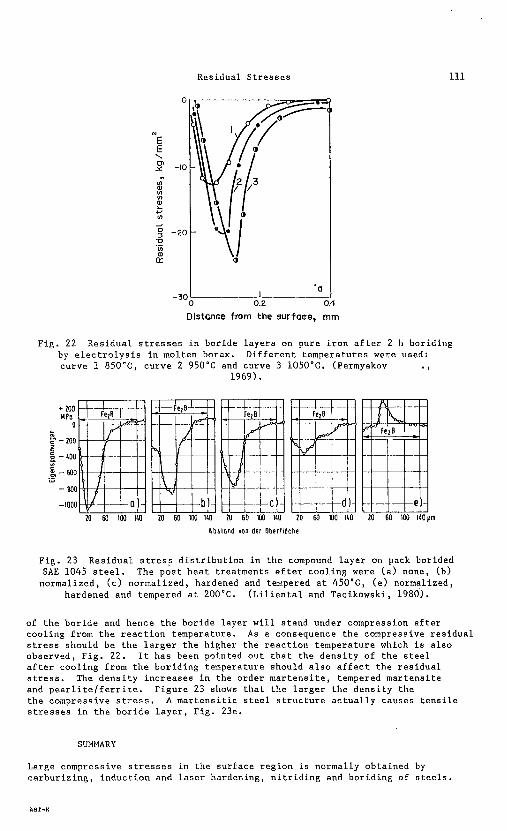
Boriding of s t e e l i s c a r r i e d o u t i n powder, s a l t ba th o r gas a t 800-1000•‹C. Boron r e a c t s wi th t h e s t e e l t o form Fe2B and FeB. By choosing s u i t a b l e c o n d i t i o n s a monophase l a y e r of Fe2B can be formed. The i n t e r f a c e between t h e s t e e l and the b o r i d e l a y e r i s very i r r e g u l a r , sometimes desc r ibed a s t o o t h shaped. I n two r e f e r e n c e s s p e c i f i c a t t e n t i o n has been pa id t o r e s i d u a l s t r e s s e s (Permyakov e t a l . , 1969 and L i l i e n t a l and Tai ikowski , 1980). The r e s i d u a l s t r e s s i n t h e - bor ide l a y e r a t room temperature i s mainly compressive, a s measured by mechanical methods, P ig . 22 and 23. The exp lana t ion g iven t o t h e occur rence of compressive s t r e s s i s t h e d i f f e r e n c e i n thermal expansion c o e f f i c i e n t between the b o r i d e phases and t h e s t e e l . The thermal expansion of the metal i s l a r g e r than t h a t
Residual S t r e s s e s
Distance from the surfaar, rnrn
F i g . 22 Res idua l s t r e s s e s i n b o r i d e l a y e r s on pure i r o n a f t e r 2 h bor id ing by e l e c t r o l y s i s i n molten borax. D i f f e r e n t t empera tu res were used: curve 1 850aC, curve 2 950•‹C and curve 3 1050•‹C. (Permyakov I
1969).
+ 100 MPo
0 c
F - 200 5 2 - roo "3
% - 600 .- ,., - en0
-1000
10 60 IW IUI 20 60 100 140 10 60 1W 140 20 60 100 140
Abslond von der Obeflloche
Fig. 23 R e s i d u a l s t r e s s d i s t r i b u t i o n i n t h e compound l a y e r on pack borided SAE 1045 s t e e l . The p o s t h e a t t r ea tments a f t e r c o o l i n g were ( a ) none, (b)
normalized, ( c ) normal ized , hardened and tempered a t 450•‹C, ( e ) normalized, hardened and tempered a t 200•‹C. ( L i l i e n t a l and Tacikowski , 1980).
of t h e b o r i d e and hence t h e bor ide l a y e r w i l l s t a n d under compression a f t e r c o o l i n g from t h e r e a c t i o n temperature. As a consequence t h e compressive r e s i d u a l s t r e s s shou ld be t h e l a r g e r t h e h igher t h e r e a c t i o n t empera tu re which i s a l s o observed, F i g . 22. It h a s been pointed o u t t h a t t h e d e n s i t y of t h e s t e e l a f t e r c o o l i n g from t h e b o r i d i n g temperature should a l s o a f f e c t t h e r e s i d u a l s t r e s s . The d e n s i t y i n c r e a s e s i n t h e o rder m a r t e n s i t e , tempered m a r t e n s i t e and p e a r l i t e l f e r r i t e . F i g u r e 23 shows t h a t t h e l a r g e r t h e d e n s i t y t h e t h e compressive s t r e s s . A m a r t e n s i t i c s t e e l s t r u c t u r e a c t u a l l y causes t e n s i l e s t r e s s e s i n t h e b o r i d e l a y e r , F i g . 23e.
SUMMARY
Large compressive s t r e s s e s i n t h e s u r f a c e r e g i o n i s normally ob ta ined by c a r b u r i z i n g , i n d u c t i o n and l a s e r ha rden ing , n i t r i d i n g and b o r i d i n g of s t e e l s .
112 T. Ericsson
Contributing factors for carburizing, induction and laser hardening are thermal stresses and density changes due to martensite formation. In carburizing the carbon gradient affects the residual stress formation indirectly by affecting the Ms temperature. For nitriding contributing factors are different thermal expansion coefficients for the phases present, growth and precipitation stresses for nitrides and stresses due to the nitrogen composition gradient. Thermal stresses can also be involved. For boriding the stresses due to the composition gradient is probably not so important as for nitriding. Martensite transformation stresses can arise in the steel substrate below the boride layer if the steel is quenched after the boriding treatment.
REFERENCES <
Ashby, M. F. and K. E. Easterling (1984) The transformation hardening of steel surfaces by laser beams - 1. Hypo-eutectoid steels. Act Met. 2, 1935-1948.
Beumelburg, W. (1974) Das Verhalten von einsat~~eharteten Proben mit verschiedenen ~berflachenzustanden und Randkohlenstoffgehalten im Umlauf biege-, statischen biegeund Schlagbiegeversuch. Dissertation, University of Karlsruhe.
Buhler, H., H. buchholz and E. H. Scheil (1932) Eigenspannungen bei der warmebehandlung von Stahl. Archiv fur das Eisenhuttewesen, 5, 413-418.
Burnett, J. A. (1977) Evaluation of elastic-plastic stresses in quenched carburized cylinders by finite element methuods. Ph.D. Thesis, University of Akron.
Courtney, C. and W. M. Steen (1981) The surface heat tretment of En 8 steel using a 2 kW C02 laser. In 2 metalworking, American Soc. Metals, Metals Park, 195-208.
Chatterjee-Fischer, R. (1973) Beispiele fur durch W&mebehandlung bedingte Eigenspannungen und ihre Auswirkungen. Harterei-~echnische Mitteilungen, 28, 276-288.
~hzterjee-Fischer, R., R. Rothe and R. Becker (19874) Uberblick uber das art en mit dem Laserstrahl. Harterei Technische Mitt., 39, 91-98.
Coleman. W. S. and M. Sim~son (1957) Residual stresses in carburized steels. In Fatigue durability of carburized steel. American Soc. Metals, Cleveland.
Denis, S., A. Simon and G. Beck (1983) Analysis of the thermochemical behaviour of steel during martensite quenching and calculation of internal stress. In E. Macherauch and V. Hauk (Eds) Eigenspannungen. Entstehung-Messung- Bewertung. Deutsche Gesellschaft fur Metallkunde, Oberursel.
Denis, S., E. Gautier, A. Simon and G. Beck (1985) Stress-phase transformation interactions: Basic principles modelization and their role in the calculation of internal stresses. Material Science and Technology, 1, 805,814.
Ericsson, T. (1982) Thermal and transformation stresses. In E. Kula and V. Weiss (Eds.). Residual stress and stress relaxation. Plenum, 19-38.
Ericsson, T., S. sjZstrZm, M. Knuuttila and B. Hildenwall (1984) Predicting residual stresses in cases. In D. E. Diesburg (~d.) Case-hardened steels: microstructural and residual stress effects. Met. Soc. AIME, Warrendale.
Ericsson, T., S.-C. Yao and M. Melander (1985) Residual stresses and microstructures in laser hardened medium and high carbon steel. In Proc. 4th Intern. Congress on Heat Treatment of Materials, Berlin, 702-733.
Ericsson, T. (1985) Thermal and austenitic thermochemical surface hardening of steel. In A. Niku-Lari (Ed.) Advances in surface treatments, 2, Pergamon Press, Oxford.
Godfrey, D. J., A. C. Hill and C. Hill (1981) A computer model for pulsed laser heating of device structures. Solid State Science and Techn., 1798-1803.
Gnanamuthu, D. S. and C. B. Shaw (1979) Laser-solid interactions and laser processiang. In AIP Conference Proc. No. 50.
Hildenwall. B. and T. Ericsson (1978) Prediction of residual stresses in case hardening steels. In Doane and J. Kirkaldy (~ds.) Hardenability concepts with application to steel. Met. Soc. AIME, Warrendale.
Hildenwall, B. (1979) Prediction of the residual stresses created during quenching. LinkGping Studies in Science and Technology, Dissertation No. 39,
I
Linkoping.
Residual Stresses
Hildenwall, B. and T. Ericsson (1980) Residual stresses in the soft pearlite layer of carburized steel. J. Heat Treating, 1, 3-13.
Ishii, K., M. Iwamoto, T. Shiraiwa and Y. Sakamoto (1971) Residual stress in the induction hardened surface of steel. SAE 710280. Soc. Automotive Eng.
Kawasumi, H. (1981) Metal surfce hardening C04 laser. In Source book on applications of the laser in metalworking', American Soc. Metals, Metals Park, 185-194.
Knuuttila, M. (1982) Computer controlled residual stress analysis and its appliction to carburized steel. Linkoping Studies in Science and Technology. Dissertation No. 81, Linkoping.
Koch, M. (1982) . Eigenspannungen nach Nitrieren und Einsatzharz. In V. Hauk and E. Macherauch (Eds.). Eigenspannungen und Lastspannungen. Hanser Verlag, Munchen, 112-121.
Koistinen, D. P. (1958) The distribution of residual stresses in carburized cases and their origin. Trans. ASM, 50, 227-241.
Li, W.-B. (1984) Laser transformation hardening of steel surfaces. Doctoral thesis 1984:35D, Lulea University of Technology.
Lilienthal, W. and J. Tacikowski (1980) Einfluss der warmebehandlung auf die Spr&digkeit von Boridschichten auf Stahlen. ~arterie Technische Mitt., 2, 251-256.
Magnusson, L. (1980) Cyclic behaviour of carburized steel. ~ i n k o ~ i n ~ Studies in Science and Technology, Dissertation No. 56, ~ i n k o ~ i n ~ .
Motoyama, M. and H. Horisawa (1971) Residual stress measurements in case- hardened steels. SAE 710281, Soc. Automotive Eng.
Melander, M. (1983) Computer calculations of residual stresses due to induction hardening. In E. Macherauch and V. Hauk (Eds.) Eigenspannungen. Entstehung- Messune-Bewertune. Deutsche Gesellschaft fur Metallkunde. Oberursel. " -
Melander, M. (1985a) A computational and experimental investigation of induction and laser hardening. ~ i n k o ~ i n ~ Studies in Science and Technology. Dissertation No. 124, Linkoping.
Melander, M. and 8.-C. Yao (1985) Theoretical and experimental study of laser transformation hardening with a toric mirror. Surface Engineering. (in press).
Melander, M. (1985b) Theoretical and experimental study of stationary and progressive induction hardening. J. of Heat Treating, 2 4, 145-166.
Mittenmeijer, E. J. (1983) the relaxation between residual macro- and microstresses and mechanical properties of case-hardened steels. In D. E. Diesburg (Ed.) Case-hardened steels: microstructural and residual stress effects, Met. Soc. AIME, Warrendale, 161-187.
Mittenmeijer, E. J . (1981) Gitterverzerrungen in nitriertem Eisen und Stahl. Harterei Technische Mitt., 2, 57-68.
Oettel, H. and B. Ehrentraut (1985) Makroskopische Eigenspannungen in der Verbindungsschicht gasnitrierter Stahle. Harterei Technische Mitt., 40, 183- 187.
Permyakov, V. G., L. Kh. Trush, A. N. Dorofeeva and A. V. Bilshenko (1969) Residual stresses in iron after nitriding, carburizing and boriding. Sovjet Materials Science, 2, 231-233.
Rozendaal, H. C. F., P. F. Collijn and E. J. Mittenmeijer (1984) Morphology, composition and residual stresses of compound layers of nitrocarburized iron and steel. In Heat Treatment '84, Metals Society, London, 31.1-31.16.
Rose. A. and H. P. Hou~ardv (1967) Transformation characteristics and - . hardenability of carburizing steels. In Transformation and hardenability in steels. Climax Molybdenum Comp. of Michigan.
Sjostrom, S. (1982) The calculation of quench stresses in steel. ~ i n k o ~ i n ~ Studies in Science and Technology. Dissertations No. 81, Linkoping.
SjGstrom, S. (1985) Interactions and constitutive models for the calculation of quench stresses in steel. Materials Science and Technology, 1, 823-829.
Yu, H. J. (1977) Berechnungen von Abkuhlungs-, Umvandlungs-, Schweiss-, Sorvie Verformungseigenspannungen mit Hilfe der Methode der Finiten Elemente. Dissertation ~niversitac Karlsruhe.
Yao, S.-C., and M. Melander (1983) Laser hardening-literature review and investigation of steels SS 2244 and SS 2258. LiTH-IKP-R-320, Linkoping University.