
Steels Micro Structure Steels Micro Structure and Properties
Ronald W. Landgraf1 and Russell A. Chernenkoffl
Residual Stress Effects on Fatigue ofSurface Processed Steels
REFERENCE: Landgraf, R. W. and Chernenkoff. R. A., "Residual Stress Effects on Fatigue ofSurface Processed Steels," Analytical and Experimental Methods for Residual Stress Effects inFatigue. ASTM STP 1004. R. L. Champoux, L H. Underwood, and L A. Kapp, Eds .. AmericanSociety for Testing and Materials, Philadelphia, 1988, pp. 1-12.
ABSTRACT: Procedures are presented for analyzing the cyclic stability and influence on fatigueresistance of residual stress patterns arising from mechanical and thermal surface processingtreatments such as shot peening and induction hardening. Cyclic properties and behavioral trendsdeveloped using smooth, axial specimens of steels simulating the various microstructures found insurface processed componentry are used to develop criteria to predict cyclic stability. the rate ofrelaxation for prescribed straining levels, the failure initiation point (surface or subsurface), andexpected fatigue lifetime. The validity of the approach is verified using experimental data from theliterature. Finally, the incorporation of these procedures in modern computer-based fatigue analysis routines, and opportunities for further enhancements, are discussed.
KEY WORDS: fatigue (steels), induction hardening, life prediction. residual stress, shot peening,stress relaxation
Ground vehicle components such as springs, shafts, and gears are routinely subjected to surface processing treatments to improve mechanical durability. The influence of processes such asshot peening, induction hardening, and carburizing on fatigue performance depends, in arather complex way, on local material properties, the service loading and, in particular, themagnitude, distribution, and stability of residual stresses. Furthermore, because of the continuing pressures to develop more efficient and lighter weight structures, there is considerableinterest in maximizing the benefits of surface processing. These factors are considered in thispaper in the context of the cyclic deformation behavior of steels and a procedure is presented foranalyzing and optimizing the fatigue resistance of surface processed componentry.
The treatment employed is based on a previously reported fatigue analysis for carburizedsteel [1]. Specifically, cyclic properties determined using axial specimens of steels simulatingthe various microstructures found in surface treated members are used to characterize fatigueresistance and residual stress effects, including cycle dependent stress relaxation. A techniquefor maximizing fatigue resistance by making failure equally likely in case and core is presentedand demonstrated with experimental results.
The current work emphasizes mechanically processed (shot peened, strain peened) and thermally processed (induction hardened) steels where residual stresses often exhibit larger effectsthan in carburized steels. In Fig. 1, typical residual stress profiles obtained with such treatments are shown. In the case of peening, strain peening-in which a part, such as a spring, isdeformed during processing-imparts higher compressive residual stresses and a deeper pattern of penetration than conventional peening does. For induction hardening, the residualstress pattern depends upon the depth of hardening and, in general, relates to the hardness
IResearch staff, Ford Motor Company, Dearborn, Ml48121.

2 RESIDUAL STRESS EFFECTS IN FATIGUE
Shot Peening
100
o'"'"CD
enc:::J'C'iii
~ -100
0.02/
II
III
II
I\ I\ I
.....~I
T500
~~ MPa--- 1
0.04 0.06Depth, inches
-- Peened----E-Peened
-200
Induction Harrlening
600l:lCDC
]400 ::r::
0.6 Tr/R 500
MPa1
----~ ...........
\\\
\ \
\
' ............
------- 200
FIG. i-Typical residual stress patterns obtained by shot peening and induction hardening.
profile as indicated in the figure. In either instance, reasonable latitude exists to alter residualstress profiles through the control of processing variables.
A major goal of this effort is to develop analysis procedures compatible with modern cumulative damage programs for predicting component fatigue life under complex service loading conditions [2]. These computer-based techniques provide material modeling routines that simulatecyclic material responses during fatigue and thus are ideally suited to handle residual stressanalysis. In the next section, approaches lOr incorporating residual stress effects in durabilityanalysis procedures are presented. This is followed by the development and demonstration ofanalysis techniques for cyclic stress relaxation and fatigue life prediction.
Durability Analysis
Fatigue analysis routines, such as those described in Ref. 2, provide a systematic frameworkfor coordinating and combining information concerning material properties, component geometry, and service loading to make estimates of service performance. These procedures are enjoying increased use in ground vehicle design with the trend towards greater reliance on analyticaldesign studies in product development programs.
The flow chart in Fig. 2 suggests an approach for incorporating surface processing effects insuch procedures. Identification of the steel and specific surface process dictate the appropriate

LANDGRAF AND CHERNENKOFF ON SURFACE PROCESSED STEELS 3
Surface Process
Peen/Ind. hrd./Carb.
Fatigue Hnalysis- fail. location- lifetime
FIG. 2-Durability analysis procedure incorporating surface processing.
material properties. Additional information regarding residual stress and hardness profiles arerequired to characterize processing effects. Based on envisioned service stresses, judgementscan then be made concerning the stability of residual stresses, that is, whether cyclic relaxationoccurs. Finally a fatigue analysis reveals the probable failure location and lifetime. When properly implemented, such tools can aid the designer in optimizing product performance throughjudicious material and processing selection.
As suggested in the above, when predicting fatigue performance, it is important to considerthe magnitude of residual stresses, both at the surface and below the surface of a component, asweU as their stability under service loading. Cycle dependent stress relaxation may negate theirpotential benefits [3,4]. A procedure for characterizing and predicting these effects is presentedin the next section.
Cycle-Dependent Stress Relaxation
Analysis
It is common to assess residual stress effects on fatigue by treating them as mean stresses[4,5]. A material's resistance to stress relaxation can then be assessed by subjecting axial specimens to biased strain cycling and observing the cyclic change in mean stress. This technique isdemonstrated by the stress-strain response in Fig. 3. Residual (mean) stresses would be expected to relax whenever the applied loading resulted in reversed plastic straining in the steel.Because of the tendency of many steels to exhibit cycle-dependent softening, this may occur atlower stresses than would be anticipated based upon monotonic yield strengths.
The cyclic stress relaxation behavior of a SAE 1045 steel at three hardness levels is shown in

4 RESIDUAL STRESS EFFECTS IN FATIGUE
SAE 1045~«/2'
1.0!~__=~::::::::===::::,::========:= g:gg~0.007'0 0.5 560 Heb _, I
.......
~ 1.0!~:::::5~ 0.5 ~Ha 0.004a:: _ -_0.005~ 1.°1~0'0015§ 0,5 0.002:102~:::::
I 10 102 103
Cycles, N
~N = ~1(N)r
[ [Mean slress, lsi cycleMean stress, Nth cycle
r = f (HB, ~E')
FIG. 3-Procedurefor determining cyclic stress relaxation rates.
Fig. 3. Using a representation suggested by Jhansale and Topper [6], the ratio of instantaneousmean stress to first cycle mean stress is plotted ag?-inst cycles on logarithmic coordinates. Therelaxation rate can thus be characterized by the slope of the line r yielding the relationshipshown in the figure.
The relaxation behavior is little affected by the magnitude of the mean stress, but dependsprimarily on material hardness and applied strain amplitude. A threshold strain amplitudebelow which relaxation would not be expected to occur can be obtained by extrapolating thedata for a particular hardness to a zero relaxation rate. This relaxation threshold can, in turn,be related to steel hardness as indicated by the relation at the bottom of Fig. 4. In this figure,the relaxation exponents for the SAE 1045 steel are plotted as a function of the ratio of appliedsli:ain amplitude to threshold strain amplitude resulting in the relationship shown. This sugpests that the relaxation exponent r for a particular steel can be estimated from hardness andstrain amplitude information.
Applications
The validity of the foregoing analysis was checked by comparing predicted results with experimental data from the literature. Mattson and Coleman [6] measured, by X-ray techniques, thechange in surface residual stresses in a shot peened SAE 5160 bending member as a result offatigue cycling. Their results, in terms of residual stress profiles before and after cycling, areshown in Fig. 5. Also shown in this figure are the strain threshold and relaxation exponentcalculated for this steel, as well as the expected change in residual stress. The agreement withexperimental results is excellent.
Bergstrom and Ericsson [8] have reported detailed X-ray measurements of the stress relax-

LANDGRAF AND CHERNENKOFF ON SURFACE PROCESSED STEELS 5
SAE 1045
... -0.2..-c::Q)c::0a.x
LLJc:: -0./ o 280 HB0
~ a 4/00 L:. 560Q)
a::
2.0 3.0 4.0
Strain Ratio, !:u/..6.~th
where:
-2 /r = 8.5x10 (1 - ~E ~Eth)
~E = applied strain range
~Eth = strain threshold-relaxation
and ~Eth/2 = exp [-8.41 + 5.36x10⁻³ (HB)J
where: HB = Brinell Hardness
FIG. 4-Procedurejor predicting relaxation ratesjrom hardness and applied strain range.
SAE 5160 (485 HB) - Shot peenedMax. stress: 240 ksi (R= 0)
0.02Depth, Inches
0.04 0.06
AO( =20ksi
.M.I =00032 th .
r =-0.028
//
//
//
//
\./!-- -N= 6xlC!: -165kSiJ22 ksi
-Initla/ value: -/87 ksi --
ot---"'----+-:f---'----...L---..J.-----I
-200
litlite
U) -100a~
"0...,a:
FIG. S-Comparison oj experimental and predicted stress relaxation in a shot peened spring steel [7].

6 RESIDUAL STRESS EFFECTS IN FATIGUE
ation during fatigue of shot peened, notched, axial specimens. Their data for three differentstress amplitudes (R = -1) are plotted in Fig. 6. The lines represent the expected relaxationbehavior based on analysis. Agreement for the highest stress level is again excellent; however, atthe lower two levels, the predicted rates are too high. This can be explained by noting that thehighest level exceeded the material yield strength, thus leading to the rapid cyclic softeningcharacteristic of such medium carbon steels. At the intermediate stress level, softening is delayed for the first 100 cycles, after which the relaxation rate is closer to the predicted one. At thelowest level, softening is not likely to occur. Since the data used in developing the analysis arebased on cyclically stabilized specimens, this apparent lack of agreement can be rationalized.
These results suggest that a complete relaxation analysis would require that cyclic softeningbe accounted for and relaxation data obtained at various degrees of stabilization. While this iscertainly an achievable task, it is worth noting that, under the spectrum loading conditionsoften found in service, a relatively few, high stress levels can trigger cyclic softening, thus resulting in behavioral patterns closer to those envisioned in the analysis. In this regard, the proposedanalysis tends to give "worst case" predictions of residual stress relaxation, hence providinguseful design information.
Before proceeding to fatigue life prediction, we consider the response of an induction hardened shaft subjected to a torsional loading spectrum as portrayed in Fig. 7. At the top of the
AISI ~l~O - Shot PeenedAxial (R=-D, Kt=1.75
(Bergs crom & Er i esson)
M·ax. Stress: 373 MPa! I
0.1 '------------"------------"
o
i()::l"0 Max. Stress: 303 MP aV\OJ0::: O. 1 '--_---<.__---"-__-'-__~_ ___' ...J
Max. Stress: 283 MPa
I I IO. " L..---:":10:----",-'-OO--1"":OO""'O--1""'OO-!-O-O-'-,0-'OO""'O-'O-·...,.'e-=.O...,.6--:-'e...J+07
Cycles
FIG. 6-Comparison of experimental and predicted (solid line) relaxation rates for shot peened notchedspecimens [8].

LANDGRAF AND CHERNENKOFF ON SURFACE PROCESSED STEELS 7
SAE 1045 - Ind. Hrd.
....Surface: no residual
1iIrf a-£. Response i
L 1 ,
__.. 1 " :
e.e
Surface: -100 I<si residual
Subsurfllce
T
FIG. 7-Surface and subsurface stress-strain simulation of an induction hardened shaft undergoing atorsional loading spectrum.
figure are computer simulations of the surface stress·str~in response: (1) with no residual stressand (2) with an initial -690 MPa (-100 ksi) residual stress. The observed compressive biasobserved in the latter case would be expected to increase fatigue life by perhaps a factor of threeto four if no relaxation were to occur. To complete the analysis, however, it is necessary toconsider the subsurface behavior in the unhardened core. This response is shown in the lowerpart of the figure and is typified by large plastic strain levels that result in surface residual stressrelaxation. In fact, in this instance, failure initiates below the surface, thus making surfaceconditions inconsequential. An analysis dealing with such situations is presented in the nextsection.

8 RESIDUAL STRESS EFFECTS IN FATIGUE
Fatigue Life Prediction
Analysis
The induction hardened shaft example serves to emphasize the importance of consideringboth surface and subsurface phenomena when analyzing surface processed componentry. Usingthe previously established analogy between mean and residual stresses, this is conveniently accomplished using the following stress-life relation (after Morrow [5])
where
(J___0__ = (2N
f)b
«(1; - (10 - (Jr) .(1)
(1;, b = material properties,(1a = stress amplitude,(10 = mean stress,(1r = residual stress, and
2Nf = life in reversals.
The application of this relation is illustrated for a bending member in Fig. 8. The individualstress gradients caused by processing and applied loading are plotted across the section fromsurface to center line. These are then combined and plotted as a damage parameter profile asindicated. Equation 1 indicates that the higher the magnitude of this parameter is, the shorterthe fatigue life. In the figure, the parameter goes through a maximum below the surface, thuspredicting subsurface crack initiation. This is often observed in surface processed membersand, in this instance, is the result of the shallow case and subsurface residual tension field.Improvements can be realized by deepening the hardening or the compressive residual stresspattern.
0.4
0.2
-1000
FIG. 8-Stress and damage parameter profiles for a surface processed bending member.

-- Peened---- f-Peened
LANDGRAF AND CHERNENKOFF ON SURFACE PROCESSED STEELS 9
.-tpplicatiolls
The utility of this analysis has been verified using fatigue results from a series of mechanically \rocessed SAE 5160 bending specimens [9]. In Fig. 9, residual stress profiles obtained by peen- \,
rng, strain peening, and strain peening followed by presetting are shown. Also shown are thefatigue lives obtained in four-point bending tests under the indicated stressing conditions. Predictions obtained using the above analysis agree closely with the experimental results. With theexception of the unpeened control specimens, all failures initiated subsurface, nominally wherethe residual stress profile became tensile. While displaying a lowered peak compressive stress,the preset specimen has a deeper pattern of penetration, hence resulting in the improved fatigueresistance observed under these testing conditions.
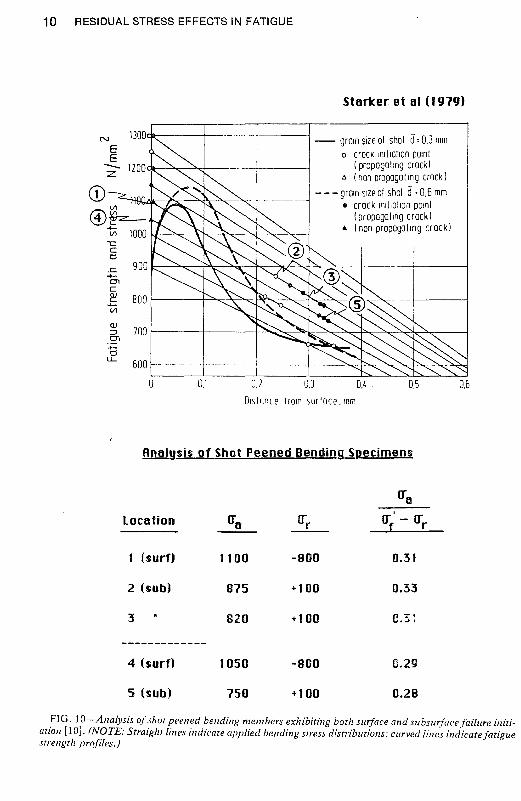
Further support for the validity of this technique is supplied using data from Starker et al.[/01 on a shot peened, hard steel. Results from bending tests of specimens treated with twodifferent shot sizes are reproduced in Fig. 10. Of interest are the two stress levels at which bothsurface and subsurface failure origins are observed. Analysis results, shown at the bottom of thefigure, confirm that such behavior is expected: compare the damage parameter for location 1with locations 2 and 3, and location 4 with location 5. Furthermore, calculated fatigue lifetimesllf 1 to 2 million reversals agree favorably with experimental results.
The foregoing examples illustrate that this rather straightforward analysis can provide a useful approach to help designers understand and optimize fatigue performance +l-,,,,,";!-'. surface
100
T500
12mml MPa
--- 1~,02 0.04. 0,06
/.;--- Depth, Inches
//"
J
,~!\ J
\ I',..,
-200 + Preset (0,00
Bending Fatigue - SHE 5160 (440 HBI
Stress ampl.lMeDn stress: 96/66 ksl
Fatigue life
IHIl1.. l!.!l..lL.
Un peened 41,400 relli. 38,000
Shot peened 149,000 146,000
Strain peened 307,000 366,000
Preset (0.00 760,000 798,000
FIG. 9-Comparison of experimental and predicted fatigue lives for a mechanically processed springsteel [9].
10 RESIDUAL STRESS EFFECTS IN FATIGUE
Starter et al (1979)
0.50.5OA .
-- grOin Size 01 shol d: 0.3 mmo crock InillOlion pOlnl
(propogollng crock)t:. (non propogolmg crack)
- - - groin size 01 shol d: 0.6 mm• crock 101l10110n pOlnl
(propogallog crock)... (non propogollOg crockl
lJ.30.20.1
ciIt-----j-----.--.. -- --
.c.-encQJ 800'--+-Vl
QJ
700::::leTa
~l.l..- 500
0
N
EE-z
OlslilOce frOIn surlocE'. mm
FIG. lO-Analysis of shot peened bending members exhibiting both swjace and subsU/facefailure initiation [10). (NOTE: Straight lines indicate applied bending stress distributions; curved lines indicatefatiguestrength profiles.)

LANDGRAF AND CHERNENKOFF ON SURFACE PROCESSED STEELS 11
rocessing. In the following section, some additional implications of the analysis are discussedP f" t .and suggestions for uture tmprovemen s presented.
Discussion
To gain additional insight into material characteristics conducive to surface processing response. it is informative to consider the variation of certain properties with hardness. In Fig. 11,lrends indicative of a range of medium to high carbon steels are shown. Fatigue strength, asindicated by a,/, increases linearly with hardness, attains a maximum at about 600 HB, anddecreases slightly thereafter. This final decrease is due. in part, to inclusion effects. With re~ard 10 residual stresses, it is noteworthy that the cyclic yield strength, S;, falls below the monownic value. s.v' at hardnesses up to SSO HB. Such cycle dependent softening promotes rapidresidual stress relaxation.
Not surprisingly. the stress amplitude threshold for relaxation shows a trend similar to that ofthe cyclic yield strength. Furthermore, at hardnesses less than SSO HB, stress relaxation can beexpected at lives of 106 reversals or longer. Finally, the influence of compressive residual stresseson fatigue resistance at 106 is largest at the highest hardnesses and diminishes rather rapidlywith decreasing hardness. Material requirements promoting strong residual stress effects are(1) a high monotonic yield strength to achieve a significant initial residual stress and (2) cj'diestability to preclude relaxation. These trends suggest that approximately a factor-of-three improvement in long-life fatigue strength is attainable through hardening, with another factor-oftwo improvement possible through residual stress effects.
500
./ 3000./
en/..:.:: 2000
en>,--T~7'-- 0en
Q.) a.."- :E- /' / /CI)
/ 5 1/ //
" Y /'1000
/ /./----- /.---- ....-""-
- .:::. - - .-'- - (00) felax.
0 0
300 2000
en200..:.::
en ~ (I06) 0en 1000 a..Q.) :E"- 100- no resid.
CI)
0 0100 300 500 700
Brinell Hardness, HB
FIG. ll-Cyclic properties of medium carbon steels as afunction of hardness.

12 RESIDUAL STRESS EFFECTS IN FATIGUE
A number of future developments can be envisioned to further extend the utility of thes€concepts. More detailed cyclic deformation models incorporating both cyclic softening andstress relaxation are needed to improve predictive accuracy. The inclusion of models to accoun1for stress-strain state effects would also prove helpful in this regard. Finally, improved crackgrowth models to account for residual stress effects, as well as conditions for nonpropagatingcracks [11,12], are needed to extend analysis capabilities. As such improvements become available, they can be readily incorporated into existing durability analysis routines, thus helping toassure their timely implementation in design practice.
This methodology can provide a quantitative basis for designers to more effectively use surface processing to achieve desired component performance objectives. Guidelines are also established for performance improvement through judicious material and process selection. Thiscapability provides a basis for developing the necessary links between design and manufacturing functions leading to process control strategies related to component service performance.
Summary
Cyclic properties and behavioral trends developed using axial specimens of steels simulatingthe various microstructures found in surface treated members have been used to develop a comprehensive procedure for analyzing residual stress effects on fatigue. Mean stress relaxationtests provide criteria for determining relaxation strain thresholds and rates of relaxation whenthe thresholds are exceeded. A stress-based life relation, incorporating mean and residual stresseffects, is used to identify the probable failure location, surface or subsurface, and expectedfatigue lifetime. Predictions based on this analysis compare favorably with a variety of experimental results taken from the literature. The incorporation of this methodology in modern,computer-based fatigue analysis procedures can provide a useful tool for designers to use moreeffectively surface processing techniques to achieve performance objectives.
References
[1] Landgraf, R. W. and Richman, R. H., in Fatigue ofComposite Materials. STP 519. American Societyfor Testing and Materials, Philadelphia, 1975, pp. 130-142.
[2] Conle, A. and Landgraf, R. W., "A Fatigue Analysis Program for Ground Vehicle Components," inProceedings. SEECO '83. International Conference on Digital Techniques in Fatigue. Society of Environmental Engineers, London, 1983, pp. 1-28.
[3] Morrow, 1., Ross, A. S., and Sinclair, G. M., Transactions. Society of Automotive Engineers, Vol. 68,1960, pp. 40-49.
[4] Hayama. T., Bulletin. JSME. Vol. 18, No. 125, 1975, pp. i194-1200.[5] Morrow. J. in Fatigue Design Handbook. AE-4. Society of Automotive Engineers. Warrendale, PA,
1968. p. 27.[6] Jhansale, H. R. and Topper, T. H., in CYCtlC Stress-Strain Behavior-Analysis. Experimentation. and
Failure Prediction. STP 519. American Society for Testing and Materials, Philadelphia, 1973, pp.246-270.
[7] Mattson, R. L. and Coleman, W. S., Transactions, Society of Automotive Engineers, Vol. 62, 1954,pp. 546-556.
[8] Bergstrom. J. and Ericsson. T., Proceedings. Second International Conference on Shot Peening. ICSP-2. American Shot Peening Society, Paramus, NJ, 1984, pp. 241-248.
[9] Landgraf, R. W. and Francis, R. c., Transactions. Society of Automotive Engineers, Vol. 88, Sect. 2,1979, p. 1485-1494.
[10] Starker, P., Wohlfahrt, H., and Macherauch, E., Fatigue Engineering Materials and Structures. Vol.I, 1979, p. 319-327.
[11] Gerber, T. L., in Achievement ofHigh Fatigue Resistance in Metals and Alloys. STP 476. AmericanSociety for Testing and Materials, Philadelphia, 1970, pp. 276-298.
[12] Fuchs, H" in Analytical and Experimental Methodsfor Residual Stress Eilects in Fatigue. STP 1004.American Society for Testing and Materials, Philadelphia, 1988, pp. 13-21.