Residual Strain ELECTE on SEP 11993 A D Class IV ... A D Class IV Flextensional Transducer Shell ......
25
AD-A268 828 Technical Report 1603 April 1993 Residual Strain ELECTE Measurement on the SEP 0 11993 Production-Grade A D Class IV Flextensional Transducer Shell J. D. Maltby Approved for public release; distribution is unlimited. N D, 93-20456 3: -- 1, 33UUUlllUU\
Transcript of Residual Strain ELECTE on SEP 11993 A D Class IV ... A D Class IV Flextensional Transducer Shell ......

AD-A268 828
Technical Report 1603April 1993
Residual StrainELECTE Measurement on theSEP 0 11993 Production-Grade
A D Class IV FlextensionalTransducer Shell
J. D. Maltby
Approved for public release; distribution is unlimited.
N D, 93-20456
3: --1, 33UUUlllUU\

Technical Report 1603April 1993
Residual Strain Measurementon the Production-Grade
Class IV FlextensionalTransducer Shell
J. D. Maltby Acc.,cesiO N &n For
NT IS C R.A&IDr•k: i/, ._
JL-AI t c Ju bh0¢a e I.-----...... .... ...... .......
By .....................................
Di-t-ibt:tioi I
Availability Co(les
Avail aidijorDist Special
All

NAVAL COMMAND, CONTROL ANDOCEAN SURVEILLANCE CENTER
RDT&E DIVISIONSan Diego, California 92152-5001
J. D. FONTANA, CAPT, USN R. T. SHEARERCommanding Officer Executive Director
ADMINISTRATIVE INFORMATION
The task reported in this document was carried out by the Structural Materials Sci-ence Branch (Code 932) of the Naval Command, Control and Ocean Surveillance Cen-ter Research, Development, Test and Evaluation (RDT&E) Division, San Diego, CA.Sponsorship was provided by in-house block funding.
Released by Under authority ofR. K. Fogg, Jr., Head C. L. Ward, Jr., HeadStructural Materials Science Branch Design and Development
Division
ACKNOWLEDGEMENTS
The author wishes to express gratitude to E. F Rynne, Jr., Head, the Acoustic Analy-sis Branch, (Code 711), for his funding support.
PK

SUMMARY
OBJECTIVE
Empirically determine the residual strain of the production-grade Class IV flextensionaltransducer shell produced by Brunswick Defense.
RESULTS
Residual stresses deduced from the strain measurements indicate that they are both additiveto and in opposition to the localized stress states experienced by the shell in-service.
CONCLUSIONS
The test data revealed that the inside fibers of the shell were under residual tension and theoutside fibers were under residual compression. The residual stresses tend to be a smallpercentage of critical in-service stresses.

CONTENTS
SU M M A RY ................................................................ i
BACKGROUND ........................................................... 1
SHELL CHARACTERISTICS ............................................... 1
PRO CED U RES ............................................................ 1
R ESU LTS ................................................................ 10
D ISCU SSIO N ............................................................ 10
CONCLU SIONS .......................................................... 16
REFERENCES ........................................................... 17
FIGURES
la. Locations of all gage placements ............................................ 2
lb. Closeup of gage placements at ring's end ..................................... 3
1c. Closeup of gage placements at ring's midbay flat .............................. 3
2. D im ensions of gages ...................................................... 4
3. Instrumented ring ready for sectioning ....................................... 7
4a. Closeup of gages placed at ring's end ........................................ 8
4b. Closeup of gages placed at ring's midbay flat .................................. 8
5. C utting the ring . ......................................................... 9
6. Picture of first saw cut .................................................... 11
7. Locations and successive order of saw cuts .................................. 11
8. Ring pieced together after completing all cuts ............................... 12
9a. Longitudinal strains recorded after cutting .................................. 12
9b. Normal strains recorded after cutting ....................................... 13
9c. Shear strains recorded after cutting . ....................................... 13
TABLES
1. Strain gage layout . ....................................................... 5
2. Final strain values after completing saw cuts ................................. 14
3. Engineering constants of Brunswick shells ................................... 14
4. R esidual stresses . ....................................................... 15
5. Critical str-eses experienced under hydrostatic pressure (reference 7) ............ 16
01. Residual stresses compared to ciitical stresses listed in taole 5 .................. 16
iii

BACKGROUND
The oval-shaped shells used in one particular Class IV flextensional transducer are filamentwound from fiberglass/epoxy by Brunswick Defense, Lincoln, NE. Lockheed Sanders Surveil-lance Systems Division, Manchester, NH, prime contractor for the transducer, purchases theseshells from Brunswick.
Early in the development of the transducer shell-when Du Pont was fabricating the shells-process-induced residual stresses were a concern in structural failures (reference 1). AlthoughBrunswick has not suffered similar problems, the residual stress information is still important toobtain a thorough undefstanding of the structural behavior of the shells. It is possible thatresidual stresses can still be a critical component to the long term stability of the shells, andresidual stress information is important to any failure prediction methodologies.
Analytical prediction of residual stresses in a composite structure is not trivial. Processingvariables determine these stresses. Brunswick uses proprietary techniques to manufacture theirshells.
In the past, structural tests on transducer shells were conducted with the aid of rosette straingages to assess the strain field through the shell thickness (reference 2). A similar approach wasundertaken in this work.
SHELL CHARACTERISTICS
Residual strains were measured on a standard transducer shell segment (8.67 inches wide)that was manufactured by Brunswick in March 1992. This was during the time that Brunswickwas under contract to build a production lot of transducer shells for Sanders. The purchased shellwas specified to be built in the same manner and configuration as the production shells.
The glass filaments used in the shells supplied by Brunswick are E-glass. The fiber orienta-tion is unidirectional, aligned perpendicular to the windowing axis (i.e., "hoop" wound). Theshells are wound on an aluminum mandrel.
Further information on the characteristics of these shells is found in reference 3.
PROCEDURES
SUMMARY
Residual strains were measured at discrete locations with electric resistance strain gages. Theshell was sawed completely through its thickness at each gage location on each side of the gagesto relieve the strains that were geometrically locked in. The measured difference in strainbetween the uncut state (i.e., the "zero strain" state) and the cut state provided the desired

residual strain information. Essentially, macrostrain states were measured; the resolution beingno finer than the size of the strain gage grid.
Residual stresses are one component contributing to the total stress state of shells. The resid-ual stress state varies as a function of temperature. In this report, we only consider the residualstrains of the shell at room temperature.
PROCEDURE DETAILS
A 2-inch-wide ring was removed from the purchased shell for testing. The ring was cut witha diamond impregnated circular saw blade mounted horizontally on a vertical knee-mill. Thisleft a rather rough end-surface.
Strain gages were mounted on the inside surface and on the much smoother end-surface thatBrunswick cut by using their standard production methods. The end-surface of the shell was fur-ther smoothed by hand with a sanding block at all of the gage locations prior to gage placement.
Gages were selectively placed at critical locations on the shell (figures la, b, and c). Table 1lists all of the locations and the type of gage used at those locations. Gage type CEA-13-125UW-350 is a general purpose single gage; gage type CEA-06-062UR-350 is a small 450 rectangularsingle-plane rosette. The dimensions of the two gage types are depicted in figure 2.
Figure Ia. Locations of all gage placements.
2

Figure lb. Closeup of gage placements at ring's end.
00 NXA
TDXAM
MIIMM ti
Figure ic. Closeup of gage placements at ring's midbay flat.
3

0.180 GRID iADTH
0.125 GAGE LENGTH
0.420 MATRIX LENGTH
0.270 MATRIXWIDTH
AXIAL GAGE
0.062 GAGE LENGTH
0.062 GRID WIDTH
0.480 MATRIX WIDTH
0\320 MATRIX LENGTH
RECTANGULAR ROSETTE
Figure 2. Dimensions of gages.
4

Table 1. Strain gage layout.
Location Orientation Gage Type Gage Factor
MXAI N CEA-062UR-350 2.10 + 1.0%
S+ ..L
MXAM N -Gage was lost-
S- CEA-06-062UR-350 2.10 + 1.0%
LMXAO N
S+
T2XAM NS_L
TDXAI NS+L ___
TlXA.33 NS_L
C2XA.33 N
LC1XAO N
S+
LMIlM L CEA-13-125UW-350 2.13 + 1.0%
TD1IM L ....
LOCATION SYNTAX
The gage syntax was similar to that used for the work reported in reference 3. Gages placedon the cross-sectional surface of the shell have an X in their location name. The first one or twocharacters before the X indicates the circumferential location of the gage around the shell's quar-ter section as follows:
M Midbay location-situated halfway down the shell's major axis;
T1 Transition location-where the end radius (3.583 inches) and the radius through theflat (approximately 43.2 inches) meet;
TD Transition location-defined as the intersection of the front normal surface of thetransducer's D-insert and the inside surface of the shell;
5

T2 Transition location-further down the shell quadrant, a chord distance of 2 inchesfrom location T1 measured along the inside surface;
C2 Curve location-160 off of the shell's major axis; and
C1 Curve location--directly on the shell's major axis.
The A in the location name indicates that all the gages are placed on the same cross-sectionalside of the ring. The last letter of the name indicates whether the gage was placed near the shell'sinside surface (1), in the middle of the shell thickness (M), or near its outside surface ,O). Gageswith the fractional number 0.33 at the end of their name (rather than a letter) were placed at adistance equal to 1/3 of the thickness from the shell's inside surface. These fractional locationswere particularly selected because of the high-shear stresses that occur at these locations underthe transducer's operational conditions (reference 4).
Each of the rectangular rosettes was oriented such that one of its gages was running parallel(denoted in table 1 with an L for longitudinal) to the fibers; one was perpendicular (denoted as Nfor normal) to the fibers; and one was oriented 450 with respect to the fiber direction (denoted asS for shear). The suffix after the S in table 1 clarifies further the orientation of the 450 sheargage. It is either positive 450 (denoted with a "+") or negative 450 (denoted with a "-") withrespect to the fiber direction, as seen in figure 1. ,Aigure 3 is a picture of the instrumented ring.
The two gages placed on the inside surface of the ring (locations M11M and TD1IM) wereoriented longitudinally in the middle of the ring's width.
Closeups of the gage placements are found in figures 4a and 4b.
6

Figure 3. Instrumented ring ready for sectioning.
7

Figure 4a. Closeup of gages placed at ring's end.
Figurc 4h. Closeup of gages placed at ring\s ridhay flat.

RING CUTrING
A bandsaw was used to cut the ring by using a carbide-impregnated blade (figure 5). Prior tocutting the ring, the gages were "zeroed" and the first data point was recorded. Data points wererecorded after each cut.
During the first cut, a tremendous clamping pressure was placed on the blade as residualstress was relieved in the shell. The clamping pressure was so great that it was not possible to cutcomp~etely through the ring until a makeshift jack, placed along the major axis of the ring, wasemployed to push the sectioned sides apart. A screwdriver was also used to pry apart the sectionsat the cut.
SI
Figure 5. Cutting the ring.
9

Figure 6 shows the first saw cut after the blade was removed. The face sections were tightlyclamped together and one face was displaced from the other due to relief of residual stress in thering.
Cuts were made as close as practical to the gages without damaging the strain gage wires.Nine cuts were made on the ring; the successive order in which they were made and their loca-tions are depicted in figure 7. Figure 8 shows the ring sections pieced together after all the cutswere completed.
RESULTS
The final strain values after all cuts were made are tabulated in table 2. These strains valuesare depicted on the shell at their respective locations in figures 9a-9c.
DISCUSSION
Residual strains that were geometrically locked into the shell are of the opposite sign to thosemeasured after cutting (table 2), which is why the table lists them as recorded strains rather thanresidual strains. For example, at the midbay flat inside surface (i.e., gage location M1IM), aresidual tensile strain of 950 microstrain existed prior to cutting. Conversely, those locationswhere strain of positive sign was recorded were under residual compression.
Stress values can be computed from the strains by using Hooke's law and the proper engi-neering constants. Table 3 lists engineering constants used in finite element modeling (reference5) of the Brunswick shells and indicates the coordinate orientations that will be assumed.
The generalized Hooke's law is greatly simplified because the material is transversely iso-tropic in the 1-3 plane. The concise constitutive relationships to determine stresses in the 1-2plane are listed as follows:
CI1 C12 C 12 0 elel
l2 = C 11 C 22 C 23 0 e
05 L0 0 0 C 5J5 e5
10

Figure 6. Picture of first saw cut.
Figure 7. Locations and successive order of saw cuts.
11
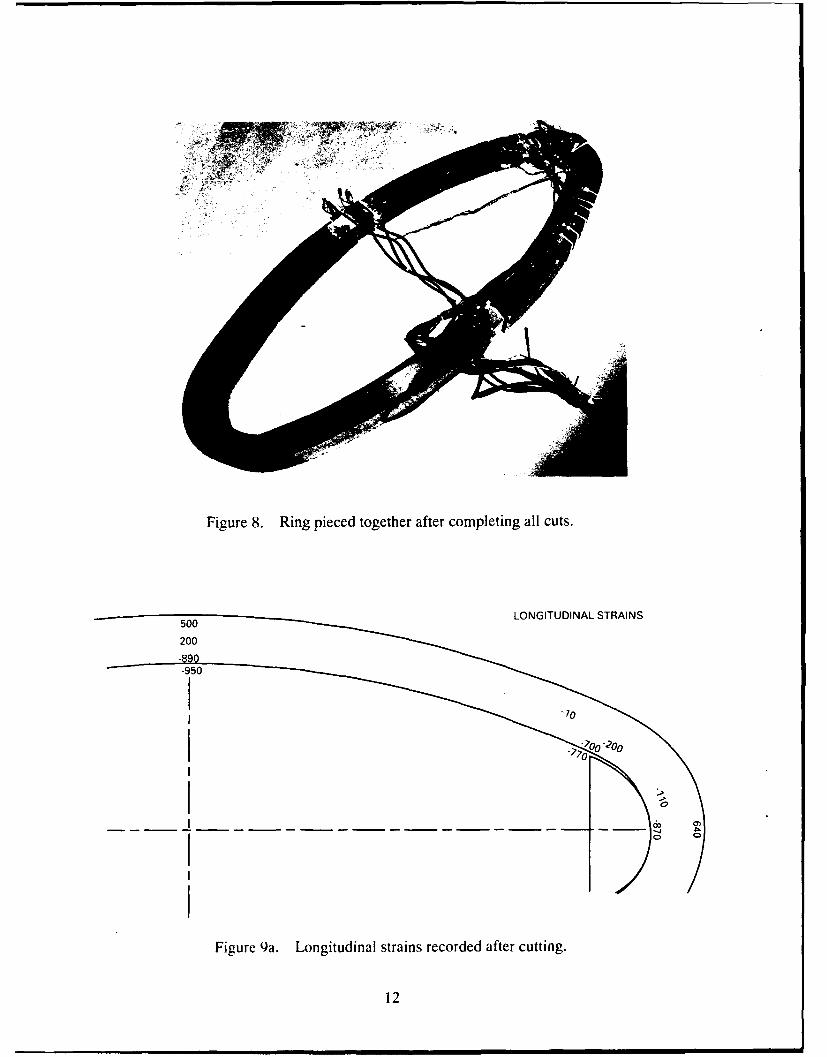
Figure 8. Ring pieced together after completing all cuts.
LONGITUDINAL STRAINS
201
-950f
I to0 -I0-
Figure 9a. Longitudinal strains recorded after cutting.
12

240 NORMAL STRAINS
Figure 9b. Normal strains recorded after cutting.
SHEAR STRAINS
-280
Figure 9c. Shear strains recorded after cutting.
13

Table 2. Final strain values after completing saw cuts.
Location Orientation Recorded Strain(microstrain)
MXAI N -20
S+ 90
L -890
MXAM N gage lost
S- -280
L 200
MXAO N 240
S+ -140
L 500
T2XAM N -20
S- 80
L -10
TDXA! N 140
S+ -240
L -700
T1XA.33 N -160
S- -210
L -200
C2XA.33 N -230
S- -120
L -110
C1XA1 N 40
S+ -370
L -870
C1XAO N -260
S+ 220
L 640
MilkM L -950
TM11M L -770
Table 3. Engineering constants of Brunswick shells.
Longitu- Radial Trans- Interlaminar Shear In-plane Poisson's Ratiodinal (x 106 verse (x 106 psi) Shear
(x 106 psi psi) (x 106 (x 106psi) psi)
E1 E2 E3 G21 G23 G 13 v21 V23 V13
5.802 1.518 1.518 0.765 0.593 0.765 0.07 0.281 0.268
14

The expressions for the Cij values in terms of the engineering constants are found elsewhere(for example, in reference 6).
Even in computing stresses only in the 1-2 plane, transverse strain (i.e., E3) information isstill required. Measuring transverse strains through the thickness is not trivial, and certainly notpractical with conventional strain gages if they are not inserted during part fabrication. Trans-verse strains could have been measured on the inside and outside ring surfaces, but that optionwas neglected. It was felt that residual strains in the transverse direction were to be governed pri-marily by Poisson effects and would be of relatively small magnitude.
One assumption to consider for stress computation is that of a plane strain condition (i.e., toassume the transverse strains are essentially of zero magnitude). Another approach is to assumethat strain magnitudes in the transverse direction are equal to those occurring in the normal (i.e.,radial) direction. Since the material is transversely isotropic, this assumption would be valid ifall the strains occurring in the plane of isotropy (i.e., the 1-3 plane) were governed by Poissoneffects.
Table 4 compares stresses computed from these two approaches, the plane strain assumptionversus the three-dimensional case where transverse strains are assumed to be equal to the radialstrains. The difference in stresses between the two approaches is slight.
Table 4. Residual stresses.
Gage Longitudinal Radial Int. Shear Longitudinal Radial Int. ShearLocation o (psi) ol (psi) a, (psi) 01 (psi) 0l (psi) a] (psi)
MXA1 5458 561 69 5470 571 69
MXAM
MXAO -3202 -704 107 -3344 -826 107
T2XAM 73 40 -61 85 50 -61
TDXAI 4200 177 184 4118 105 184
T1XA.33 1319 390 161 1413 472 161
C2XA.33 809 456 92 945 573 92
CIXAI 5300 447 283 5276 427 283
C1XAO -3762 63 -168 -3608 195 -168
The significance of these residual stresses is better understood when they are compared toin-service shell stresses. Table 5 lists the general location and magnitude of critical stressestypically experienced by the composite shell under hydrostatic pressure. These results, takenfrom reference 7, were gleaned from finite element results on one] particular Brunswick shelltransducer configuration subjected to 350-psi hydrostatic pressure. Table 6 lists select gageslocated in the vicinity of the critical stress locations, and states whether or not the residual
I Reference 7 compares six Brunswick shells, each possessing relatively minor differences in thickness. Stresses from shell #3 in that studywere sclected because it was the only one that did not form a gap at the D-insert when subjected to 350 psi. A prime effect of gapping is togreatly increase the radial stress at the D-insert contact region.
15

stresses at those locations are additive or in opposition to the critical stresses. Table 6 also liststhe magnitude of the residual stresses as a percentage of the critical stress values.
Table 5. Critical stresses experienced under hydrostatic pressure (reference 7).
Longitudinal Radial Int. Sheara, (psi) 02 (psi) 05 (psi)
Critical stress 42,886 psi at flat inner 1,691 psi at D-insertvalues and locations surface contact region
-57,796 psi at curve -9,436 psi at D-insert -5,256 psi at transitioninner surface contact region neutral axis
Table 6. Residual stresses compared to critical stresses listed in table 5.
Gage Location Longitudinal Radial Int. Shear
01 (psi) 02 (psi) 05 (psi)
MXAI Additive (13%)
T2XAM Additive (1%)
TDXAI In opposition (-7%) Additive (10%) orIn opposition (-2%)*2
T1XA.33 In opposition (-3%)
CIXAI In opposition (-9%) _ _1
CONCLUSIONS
The test data revealed that the inside fibers of the shell were under residual tension and theoutside fibers were under residual compression, analogous to a bent beam. This corroborates theinward bending behavior that was observed after the first cut was made (figure 6).
When compared to critical stresses experienced by the shell in-service, residual stresses areboth beneficial (being in opposition to those stresses) and adverse to these stresses, depending onthe shell location at which they are evaluated. In either case, they tend to be a small percentageof critical in-service.
2 Finite element results (references 4, 5, 6) indicate that large stress gradients can occur at the D-insert contact region. Residual peel stressrecorded at location TDXAI may be either additive or in opposition to radial stresses at the location depending on the specific service pres-sure at which they are evaluated.
16

REFERENCES
1. Sanders Surveillance Systems Division. Contractor's Monthly Progress and Status Report,"High Power Acoustic Projector, Report No. 13," Contract N66001-86-C-00227. June 1988.
2. Maltby, J. D. "Static Structural Tests on Composite Flextensional Transducer Shells," NOSCTechnical Report 1447, October 1991.
3. Maltby, J. D. "Evaluation of Production-Grade Class IV Flextensional Transducer Shell,"NRaD Technical Report 1604, April 1993.
4. Shaw, R. C. "Finite Element Analysis of Composite Flextensional Transducer Shell," NOSCTechnical Report 1467, December 1991.
5. Shaw, R. C. "Structural Analysis of Flextensional Transducer-Progress Report No. 4,"NRaD Memorandum Ser 933/04-92. 28 January 92.
6. Tsai, S. W. Composites Design, Think Composites, Dayton, Ohio. Third Edition, pp. 3-1 to3-8. 1987.
7. Shaw, R. C. "Thickness Tolerance Study of Brunswick and Fibertek Shells," NRaD Memo-randum Ser 933/74-92. 6 November 1992.
17

Form ApprovedREPORT DOCUMENTATION PAGE OMB No. 070188
Public reporting burden for this collection of information is estimated to average 1 hour per response. including the time for reviewing instructions, searching existing data sources, gathering andmaintaining the data needed, and completing and reviewing the collection of information. Send comments regarding this burden estimate or any other aspect of this collection of information, includingsuggestions for reducing this burden, to Washington Headquarters Seivices. Directorate for Information Operations and Reports, 1215 Jefferson Davis Highway. Suite 1204, Arlington. VA22202-4302, and to the Office of Management and Budget, Paperwork Reduction Project (0704-0188). Washington DC 20503
1. AGENCY USE ONLY (Leave blank) 2. REPORT DATE 3. REPORT TYPE AND DATES COVERED
April 1993 Final
4. TITLE AND SUBTITLE 5. FUNDING NUMBERS
RESIDUAL STRAIN MEASUREMENT ON THE PRODUCTION-GRADECLASS IV FLEXTENSIONAL TRANSDUCER SHELL PE: 0602314N
6 AUTHOR(S) WU: DN306257
J. D. Maltby
7 PERFORMING ORGANIZATION NAME(S) AND ADDRESS(ES) 8. PERFORMING ORGANIZATIONREPORT NUMBER
Naval Command, Control and Ocean Surveillance Center (NCCOSC)RDT&E Division TR 1603San Diego, CA 92152-5001
9 SPONSORING/MONITORING AGENCY NAME(S) AND ADDRESS(ES) 10. SPONSORING/MONITORINGAGENCY REPORT NUMBER
In-house
11. SUPPLEMENTARY NOTES
12a DISTRIBUTION/AVAILABIUTY STATEMENT 12b. DISTRIBUTION CODE
Approved for public release; distribution is unlimited.
13. ABSTRACT (Maximum 200 words)
This document reports on the task to empirically determine the residual strain state of a production-grade flextensionaltransducer shell.
14 SUBJECT TERMS 15 NUMBER OF PAGES
strain gages residual stress 26
critical stress 16 PRICE CODE
17 SECURITY CLASSIFICATION 18 SECURITY CLASSIFICATION 19 SECURITY CLASSIFICATION 20 LIMITATION OF ABSTRACTOF REPORT OF THIS PAGE OF ABSTRACT
UNCLASSIFIED UNCLASSIFIED UNCLASSIFIED SAME AS REPORT
NSN 7540-01-280-5500 Standard form 298 (FRONTI
UNCLASSIFIED
21a. NAME OF RESPONSIBLE WIAL. 21b. TELEPONE ft-hU C) AMc OP cE SYM•IO
J. D. Maltby (619) 553-1176 Code 932
NSN 7540-01-MM0-60 M g US
UNCLASSIFIED

INITIAL DISTRIBUTION
Code 0012 Patent Counsel (1)Code 70 R. E. Shutters (1)Code 71 T. F. Ball (1)Code 711 E. F. Rynne, Jr. (2)Code 711 J. DeJaco (1)Code 711 WV F. Rask (1)Code 712 C. S. Nichols (2)Code 712 C. Meland (1)Code 712 P A. Hanson (1)Code 90 1. Lemaire (1)Code 93 C. L. Ward, Jr. (1)Code 932 R. K. Fogg, Jr. (1)Code 932 J. D. Maltby (2)Code 961 Archive/Stock (6)Code 964B Library (2)
Defense Technical Information CenterAlexandria, VA 22304-6145 (4)
NCCOSC Washington Liaison OfficeWashington, DC 20363-5 100
Center for Naval AnalysesAlexandria, VA 22302-0268
Navy Acquisition, Research and DevelopmentInformation Center (NARDIC)
Washington, DC 20360-5000
GIDEP Operations CenterCorona, CA 91718-8000
NCCOSC Division DetachmentWarminster, PA 18974-5000
Naval Air Warfare CenterAircraft DivisionWarminster, PA 18974-5000
Office of Naval ResearchArlington, VA 22217-5000
Space and Naval Warfare Systems Command2451 Crystal DriveArlington, VA 22245-5200
Naval Research LaboratoryUnderwater Sound Reference DetachmentOrlando, FL 32856-8337