Residual Life Assessment and Microstructure - …ommi.co.uk/etd/eccc/advancedcreep/V6i1x.pdf ·...
36
ECCC RECOMMENDATIONS - VOLUME 6 [Issue 1] Residual Life Assessment and Microstructure ECCC
Transcript of Residual Life Assessment and Microstructure - …ommi.co.uk/etd/eccc/advancedcreep/V6i1x.pdf ·...
ECCC RECOMMENDATIONS - VOLUME 6 [Issue 1]
Residual Life Assessment and Microstructure
ECCC

AC/MC/93 [Issue 1] 27/07/05
blank page
AC/MC/93 [Issue 1] 27/07/05
ECCC RECOMMENDATIONS - VOLUME 6 [Issue 1]
Residual life assessment and microstructure
PREPARED BY ECCC - WG1.1 Dr. S. Brett RWE npower (United Kingdom) Dr. L.W. Buchanan Mitsui Babcock (United Kingdom) Dr. S. Concari CESI (Italy) Dr. G. L. Cosso Istituto Italiano Saldatura (Italy) Dr. S. Fenton E-ON UK (United Kingdom) Dr. A. Fleming ETD (United Kingdom) [Secretary 2004] Dr. R. Hales ETD (United Kingdom) [Secretary 2001-2003] Dr. V. Kanta Skoda (Czech Republic) Dr. I. Marcelles Tecnatom (Spain) Dr-Ing G Merckling Istituto Scientifico Breda (Italy) [Convenor] Dr D G Robertson ETD (United Kingdom) [Secretary 2005] Dr-Ing P Seliger Siempelkamp (Germany)
EDITED BY: S. CONCARI
APPROVED DATE 31/8/05
On behalf of ECCC

AC/MC/93 [Issue 1] 27/07/05
blank page
AC/MC/93 [Issue 1] 27/07/05
ABSTRACT ECCC Recommendations - Volume 6 Part x gives an overview of the correlation among residual life assessment and microstructural aspect, including also hardness, for post exposed material in creep conditions. Overview includes also description of techniques applied for microstructural investigation of in-service components. Recommendations on utilisation of the correlation and for further development of this subject are presented. This document is in the first issues and is not yet to be considered as an exhaustive reference source; the volume 6 part x would be expanded and enhanced based on feedback from users. ECCC Recommendations Volume 6 user feedback is encouraged and should be sent to: Dr. S. Concari [Document Controller] CESI FAS DIG Sede di Piacenza Via N. Bixio, 39 I-29100 Piacenza, Italy. Tel: +39 0523 684219 Fax: +39 0523 684387 E-mail: [email protected] ECCC may from time to time re-issue this document in response to new developments. The user is advised to consult the Document Controller for confirmation that reference is being made to the latest issue.
This document shall not be published without the written permission of the ECCC Management Committee

AC/MC/93 [Issue 1] 27/07/05
blank page
- 1 - AC/MC/93 [Issue 1]
27/07/05
Residual Life Assessment and Microstructure Contents 1 Microstructure ........................................................................................................................................... 2
1.1 Ferritic steels ..................................................................................................................................... 2 1.1.1 Microstructural phase evolution ................................................................................................ 2 1.1.2 Microvoids formation at grain boundaries ................................................................................ 6 1.1.3 Carbide evolution .................................................................................................................... 14 1.1.4 Interparticle distance................................................................................................................ 20
1.2 Other materials ................................................................................................................................ 22 2 Techniques applied for investigation on in-service components............................................................. 23
2.1.1 Replica investigation ............................................................................................................... 23 2.1.2 Extractive replica..................................................................................................................... 24
3 Hardness .................................................................................................................................................. 25 4 Comments................................................................................................................................................ 26 5 Final recommendations ........................................................................................................................... 27 6 Bibliography ............................................................................................................................................ 28
- 2 - AC/MC/93 [Issue 1]
27/07/05
Foreword
"Components subjected to creep stress have a limited lifetime. Under the influence of temperature and
stresses, the heat resistant materials react by creeping, whereby transformations, and segregations,
precipitations occur in the structure of these materials."
As stated above by W. Arnswald, R. Blum, B. Neubauer, K.E. Poulsen in a document published on VGB
Kraftwerkstechnik in July 1979, creep and material structure evolution are tightly related and according to
this rule a large number of studies have been performed in order to relate microstructural investigation and
service exposure or residual life.
This chapter is intended to give an overview of the existing applied (more or less frequently) techniques of
microstructural investigation in order to assess residual life, and to state recommendations about their
applicability.
1 Microstructure
1.1 Ferritic steels
As far as this type of material is concerned, the aspects mainly considered valid as an index of creep
exposure are:
- Microstructural phase evolution
- Microvoid formation at grain boundaries (Neubauer etc.)
- Evolution of carbides (eutectoidic and ferritic fine precipitation)
- Interparticle distance
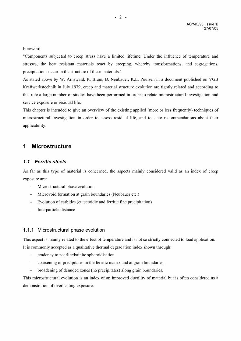
1.1.1 Microstructural phase evolution
This aspect is mainly related to the effect of temperature and is not so strictly connected to load application.
It is commonly accepted as a qualitative thermal degradation index shown through:
- tendency to pearlite/bainite spheroidisation
- coarsening of precipitates in the ferritic matrix and at grain boundaries,
- broadening of denuded zones (no precipitates) along grain boundaries.
This microstructural evolution is an index of an improved ductility of material but is often considered as a
demonstration of overheating exposure.
- 3 - AC/MC/93 [Issue 1]
27/07/05
Figure 1 – Microstructural phase evolution generic aspect
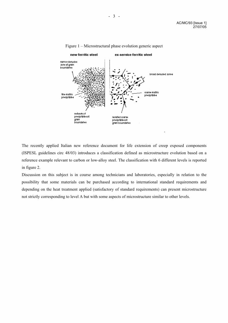
The recently applied Italian new reference document for life extension of creep exposed components
(ISPESL guidelines circ 48/03) introduces a classification defined as microstructure evolution based on a
reference example relevant to carbon or low-alloy steel. The classification with 6 different levels is reported
in figure 2.
Discussion on this subject is in course among technicians and laboratories, especially in relation to the
possibility that some materials can be purchased according to international standard requirements and
depending on the heat treatment applied (satisfactory of standard requirements) can present microstructure
not strictly corresponding to level A but with some aspects of microstructure similar to other levels.
- 4 - AC/MC/93 [Issue 1]
27/07/05
Figure 2 – ISPESL classification for microstructure evolution of ferritic steels
1.1.1.1 Coarsening coefficient of carbides
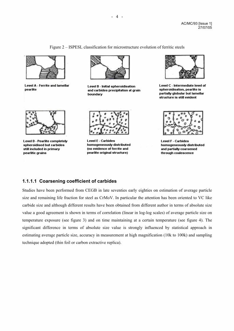
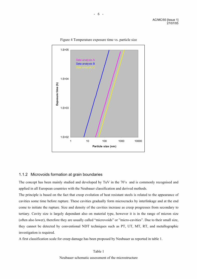
Studies have been performed from CEGB in late seventies early eighties on estimation of average particle
size and remaining life fraction for steel as CrMoV. In particular the attention has been oriented to VC like
carbide size and although different results have been obtained from different author in terms of absolute size
value a good agreement is shown in terms of correlation (linear in log-log scales) of average particle size on
temperature exposure (see figure 3) and on time maintaining at a certain temperature (see figure 4). The
significant difference in terms of absolute size value is strongly influenced by statistical approach in
estimating average particle size, accuracy in measurement at high magnification (10k to 100k) and sampling
technique adopted (thin foil or carbon extractive replica).
- 5 - AC/MC/93 [Issue 1]
27/07/05
Figure 3 Particle size vs. temperature (for defined time)
Average size after 1000 hours at T
10
100
1000
550 600 650 700T (°C)
Particle size (nm)
Data analysis AData analysis B
- 6 - AC/MC/93 [Issue 1]
27/07/05
Figure 4 Temperature exposure time vs. particle size
1.E+02
1.E+03
1.E+04
1.E+05
1 10 100 1000 10000
Particle size (nm)
Expo
sure
tim
e (h
)Data analysis AData analysis BData analysis C
1.1.2 Microvoids formation at grain boundaries
The concept has been mainly studied and developed by TuV in the 70’s and is commonly recognised and
applied in all European countries with the Neubauer classification and derived methods.
The principle is based on the fact that creep evolution of heat resistant steels is related to the appearance of
cavities some time before rupture. These cavities gradually form microcracks by interlinkage and at the end
come to initiate the rupture. Size and density of the cavities increase as creep progresses from secondary to
tertiary. Cavity size is largely dependant also on material type, however it is in the range of micron size
(often also lower), therefore they are usually called “microvoids” or ”micro-cavities”. Due to their small size,
they cannot be detected by conventional NDT techniques such as PT, UT, MT, RT, and metallographic
investigation is required.
A first classification scale for creep damage has been proposed by Neubauer as reported in table 1.
Table 1
Neubauer schematic assessment of the microstructure

- 7 - AC/MC/93 [Issue 1]
27/07/05
Grade of evolution Structural assessment observed by metallography
0 Normal microstructure for new component
1 Normal microstructure for service conditions, incipient or
advanced structural transformation or precipitation
2 Advanced creep load
a) chain shaped, oriented carbides on grain boundaries
b) isolated micropores (cavities on grain boundaries),
irregularly distributed
c) few micropores (cavities on grain boundaries) irregularly
distributed
3 Incipient creep damage
a) micropores (cavities on grain boundaries) orientation
vertically to the direction of main stress
b) grain boundary separation (length of one grain)
4 Advanced creep damage
Microcracks (length of several grains) identifiable
5 Structural loosening (grain disintegration)
Macrocracks (length of the millimetre range)
Evolution of Neubauer classification can be found in different European countries varying from a simplified
approach to a more detailed classification.
A simplified approach of Neubauer damage classification can be found in the Italian ISPESL Guidelines 002
(reference document for creep classification applied in Italy) where the Neubauer classification is limited to
the five different grades with an indicative representation of damage aspect as reported in table 2.
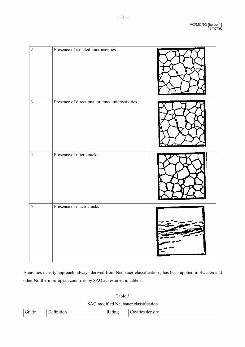
Table 2
ISPESL simplified Neubauer classification
Grade Microstructure Picture
0 New material
1 Normal (no cavities)
- 8 - AC/MC/93 [Issue 1]
27/07/05
2 Presence of isolated microcavities
3 Presence of directional oriented microcavities
4 Presence of microcracks
5 Presence of macrocracks
A cavities density approach, always derived from Neubauer classification , has been applied in Sweden and
other Northern European countries by SAQ as resumed in table 3.
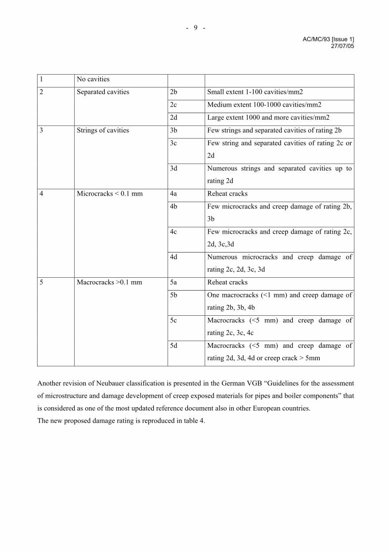
Table 3
SAQ modified Neubauer classification
Grade Definition Rating Cavities density
- 9 - AC/MC/93 [Issue 1]
27/07/05
1 No cavities
2b Small extent 1-100 cavities/mm2
2c Medium extent 100-1000 cavities/mm2
2 Separated cavities
2d Large extent 1000 and more cavities/mm2
3b Few strings and separated cavities of rating 2b
3c Few string and separated cavities of rating 2c or
2d
3 Strings of cavities
3d Numerous strings and separated cavities up to
rating 2d
4a Reheat cracks
4b Few microcracks and creep damage of rating 2b,
3b
4c Few microcracks and creep damage of rating 2c,
2d, 3c,3d
4 Microcracks < 0.1 mm
4d Numerous microcracks and creep damage of
rating 2c, 2d, 3c, 3d
5a Reheat cracks
5b One macrocracks (<1 mm) and creep damage of
rating 2b, 3b, 4b
5c Macrocracks (<5 mm) and creep damage of
rating 2c, 3c, 4c
5 Macrocracks >0.1 mm
5d Macrocracks (<5 mm) and creep damage of
rating 2d, 3d, 4d or creep crack > 5mm
Another revision of Neubauer classification is presented in the German VGB “Guidelines for the assessment
of microstructure and damage development of creep exposed materials for pipes and boiler components” that
is considered as one of the most updated reference document also in other European countries.
The new proposed damage rating is reproduced in table 4.
- 10 - AC/MC/93 [Issue 1]
27/07/05
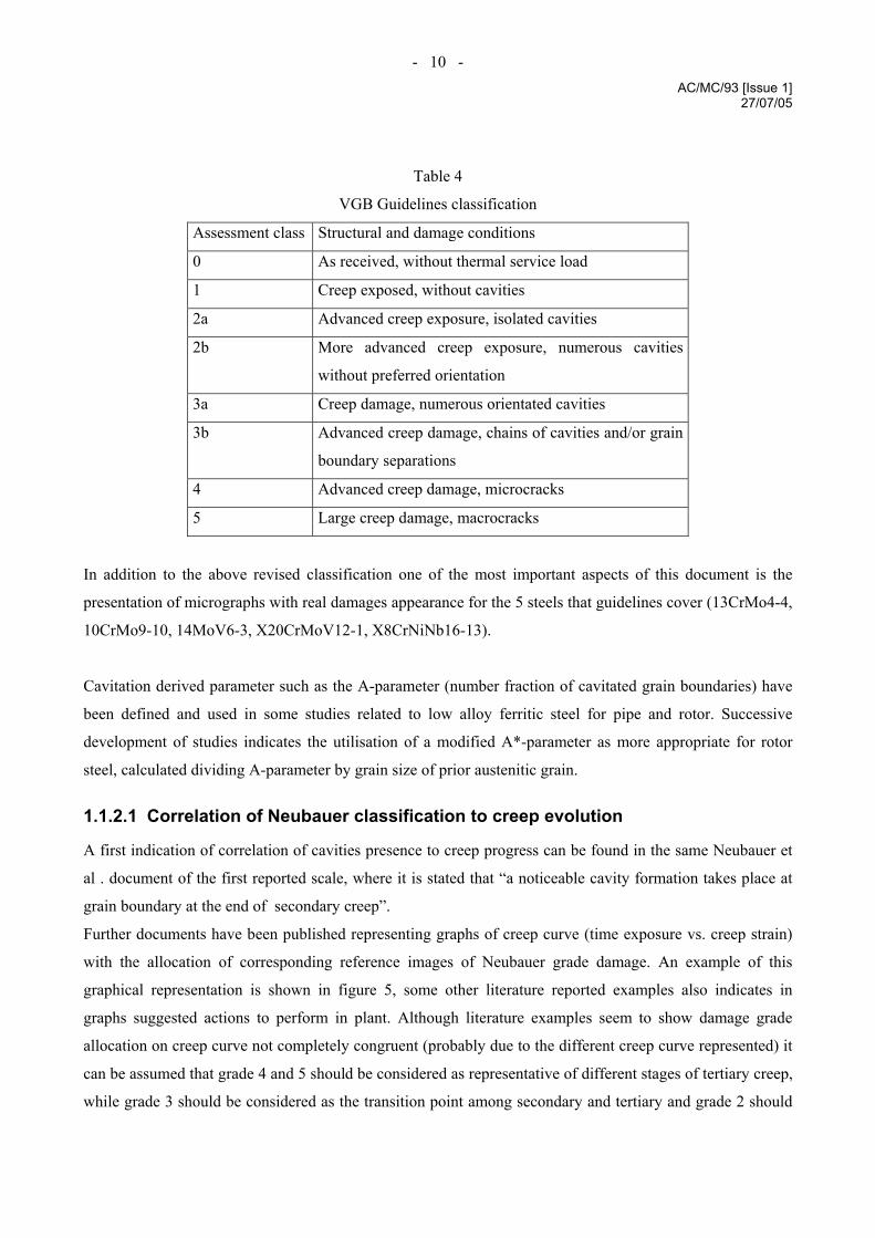
Table 4
VGB Guidelines classification
Assessment class Structural and damage conditions
0 As received, without thermal service load
1 Creep exposed, without cavities
2a Advanced creep exposure, isolated cavities
2b More advanced creep exposure, numerous cavities
without preferred orientation
3a Creep damage, numerous orientated cavities
3b Advanced creep damage, chains of cavities and/or grain
boundary separations
4 Advanced creep damage, microcracks
5 Large creep damage, macrocracks
In addition to the above revised classification one of the most important aspects of this document is the
presentation of micrographs with real damages appearance for the 5 steels that guidelines cover (13CrMo4-4,
10CrMo9-10, 14MoV6-3, X20CrMoV12-1, X8CrNiNb16-13).
Cavitation derived parameter such as the A-parameter (number fraction of cavitated grain boundaries) have
been defined and used in some studies related to low alloy ferritic steel for pipe and rotor. Successive
development of studies indicates the utilisation of a modified A*-parameter as more appropriate for rotor
steel, calculated dividing A-parameter by grain size of prior austenitic grain.
1.1.2.1 Correlation of Neubauer classification to creep evolution
A first indication of correlation of cavities presence to creep progress can be found in the same Neubauer et
al . document of the first reported scale, where it is stated that “a noticeable cavity formation takes place at
grain boundary at the end of secondary creep”.
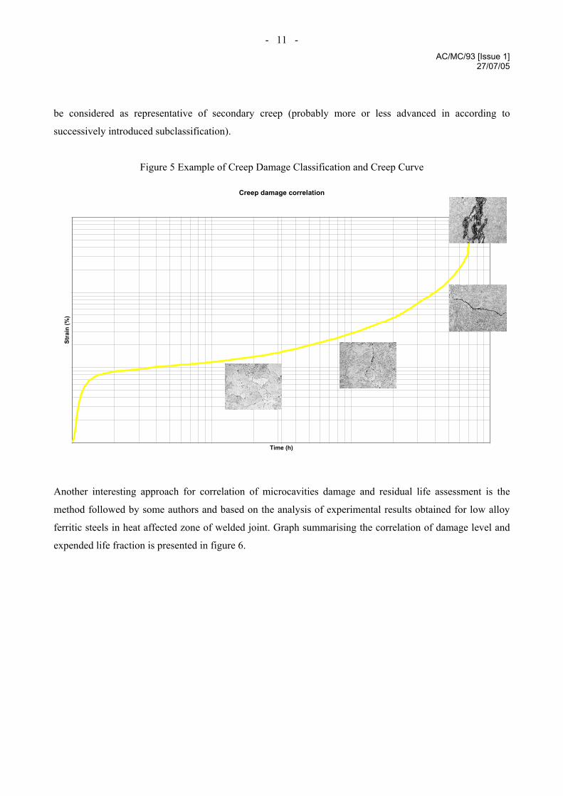
Further documents have been published representing graphs of creep curve (time exposure vs. creep strain)
with the allocation of corresponding reference images of Neubauer grade damage. An example of this
graphical representation is shown in figure 5, some other literature reported examples also indicates in
graphs suggested actions to perform in plant. Although literature examples seem to show damage grade
allocation on creep curve not completely congruent (probably due to the different creep curve represented) it
can be assumed that grade 4 and 5 should be considered as representative of different stages of tertiary creep,
while grade 3 should be considered as the transition point among secondary and tertiary and grade 2 should
- 11 - AC/MC/93 [Issue 1]
27/07/05
be considered as representative of secondary creep (probably more or less advanced in according to
successively introduced subclassification).
Figure 5 Example of Creep Damage Classification and Creep Curve
Creep damage correlation
Time (h)
Stra
in (%
)
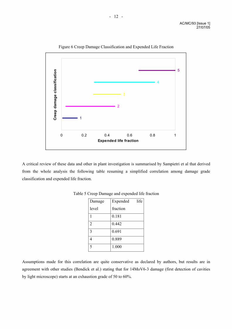
Another interesting approach for correlation of microcavities damage and residual life assessment is the
method followed by some authors and based on the analysis of experimental results obtained for low alloy
ferritic steels in heat affected zone of welded joint. Graph summarising the correlation of damage level and
expended life fraction is presented in figure 6.
- 12 - AC/MC/93 [Issue 1]
27/07/05
Figure 6 Creep Damage Classification and Expended Life Fraction
1
2
3
4
5
0 0.2 0.4 0.6 0.8 1Expended life fraction
Cre
ep d
amag
e cl
assi
ficat
ion
A critical review of these data and other in plant investigation is summarised by Sampietri et al that derived
from the whole analysis the following table resuming a simplified correlation among damage grade
classification and expended life fraction.
Table 5 Creep Damage and expended life fraction
Damage
level
Expended life
fraction
1 0.181
2 0.442
3 0.691
4 0.889
5 1.000
Assumptions made for this correlation are quite conservative as declared by authors, but results are in
agreement with other studies (Bendick et al.) stating that for 14MoV6-3 damage (first detection of cavities
by light microscope) starts at an exhaustion grade of 50 to 60%.
- 13 - AC/MC/93 [Issue 1]
27/07/05
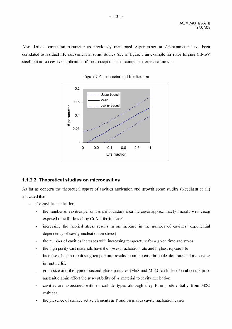
Also derived cavitation parameter as previously mentioned A-parameter or A*-parameter have been
correlated to residual life assessment in some studies (see in figure 7 an example for rotor forging CrMoV
steel) but no successive application of the concept to actual component case are known.
Figure 7 A-parameter and life fraction
0
0.05
0.1
0.15
0.2
0 0.2 0.4 0.6 0.8 1
Life fraction
A p
aram
eter
Upper bound
Mean
Low er bound
1.1.2.2 Theoretical studies on microcavities
As far as concern the theoretical aspect of cavities nucleation and growth some studies (Needham et al.)
indicated that:
- for cavities nucleation
- the number of cavities per unit grain boundary area increases approximately linearly with creep
exposed time for low alloy Cr-Mo ferritic steel,
- increasing the applied stress results in an increase in the number of cavities (exponential
dependency of cavity nucleation on stress)
- the number of cavities increases with increasing temperature for a given time and stress
- the high purity cast materials have the lowest nucleation rate and highest rupture life
- increase of the austenitising temperature results in an increase in nucleation rate and a decrease
in rupture life
- grain size and the type of second phase particles (MnS and Mo2C carbides) found on the prior
austenitic grain affect the susceptibility of a material to cavity nucleation
- cavities are associated with all carbide types although they form preferentially from M2C
carbides
- the presence of surface active elements as P and Sn makes cavity nucleation easier.
- 14 - AC/MC/93 [Issue 1]
27/07/05
- For cavities growth
- Same correlation as cavities nucleation with stress
- Increasing of the austenitising temperature results in an increase in cavities growth rate
- Two are the mechanisms that control cavities growth: diffusion growth and constraint growth,
the first is dominating at intermediate and high stress level, the second one is dominating at the
lower stresses.
Same authors proposed also an algorithm for remnant life prediction of low alloy ferritic steel based on the
estimation of area fraction of grain boundary that is cavitated at time t, but it is not known a frequent
application in industry of this kind of algorithm.
1.1.3 Carbide evolution
Many significant studies have been conducted on the evolution of carbides present in steels due to creep
exposure. Separation and coarsening of carbides is in general an index of material degradation due to creep
exposure. A detailed description of the most commonly present carbides in low alloy steels with their
composition and tendency to evolution with high temperature service is presented in an old paper of
Woodhead et al.
The most important class of carbides that are present in low alloy creep resistant steels are:
M3C
Essentially cementite Fe3C but often including other metallic elements (in particular Mn), the content of
these other elements is controlled by element tendency to partitioning among ferrite matrix and affinity to
carbon for carbide formation. This group of carbides has the same orthorombic structure of cementite.
M7C3
A family of chromium rich carbides with trigonal structure that can include also Mn , Mo and V.
M23C6
Typically Mo and W carbides for steels containing these elements, and Cr based carbides for other steels not
containing Mo and W. These carbides have a significant tendency to include also Fe and Mn.
M6C
Essentially a ternary carbide of Fe and Mo or Fe and W with an appreciable solubility for other elements
MC
Carbides with cubic structure mainly formed by V, Nb, and Ti. For vanadium carbides V4C3 concentration is
considered as pertinent to same group of VC. Mo and W carbides of the same concentration are generally
considered separately due to the different kind of structure (hexagonal).
M2C
Usually a Mo rich carbide with face centred cubic structure.
- 15 - AC/MC/93 [Issue 1]
27/07/05
Presence of different classes of carbides in steel is related to global composition and thermal process applied
in manufacturing. Phase diagram with different parametric element concentration (binary or ternary) are
available for studying equilibrium condition of carbide formation and evolution.
Very limited are the published information available (Benvenuti et al.) on the practical application of these
studies in the field of maintenance investigation in industry. Some experiences are however known of trial
monitoring of carbides evolution on plants through the utilisation of extractive replicas or low invasive
sampling methods like those applied for small punch or indentation tests.
In this experiences of monitoring carbide evolution through extractive replica for a defined low ferritic steel,
a simplified method of identification of main carbides classes (M3C, M7C3, M23C6 and M6C) and statistical
distribution of carbides among these classes has been utilised as index of creep exposure effect on material.
The analysis consists on the examination of precipitates collected through extractive replica with
morphological evaluation of eutectoidic precipitates and fine particles dispersed in ferritic matrix, chemical
composition determination of a defined number (statistically considered satisfactory) of carbides and
representation of the detected carbides on ternary diagram where area corresponding to main classes of
carbides are defined. Figure 8 shows an example of carbides ternary diagram for a low alloy ferritic steel
with comparison of virgin and service exposed materials.

- 16 - AC/MC/93 [Issue 1]
27/07/05
Figure 8 - Carbides ternary diagrams in virgin and service exposed low alloy ferritic steel
In the same study comparison of carbides composition in cold and hot locations of the same service exposed
component have been made also on the basis of Cr/Fe ratio for M23C6 and M7C3 carbides and Mo/Fe ratio in
M6C carbides.
A large characterisation (Benvenuti et al.) of seventeen P22 steam pipes in virgin state showed that big
variation in microstructure related parameters exist although the material was purchased according to the
same standard specification. Among these parameter related to microstructure, carbides composition showed
anyway less severe scatter.
The study of carbide composition evolution in P22 steam pipes service exposed, allowed to establish that
most regular trend is the Cr enrichment in M23C6 and a linear correlation has been estimated for Cr/Fe ratio
(in M23C6 carbides) with service time cubic root for the defined temperature of 540°C.
Cr/Fe = 0.32843 + 0.01653 t 1/3
The same authors in successive studies show a similar diagram of Cr/Fe ratio in M23C6 carbides versus
exposure time for P22 material at T=540°C. with a slightly modified equation.
Cr/Fe = 0.33362 + 0.01516 t 1/3
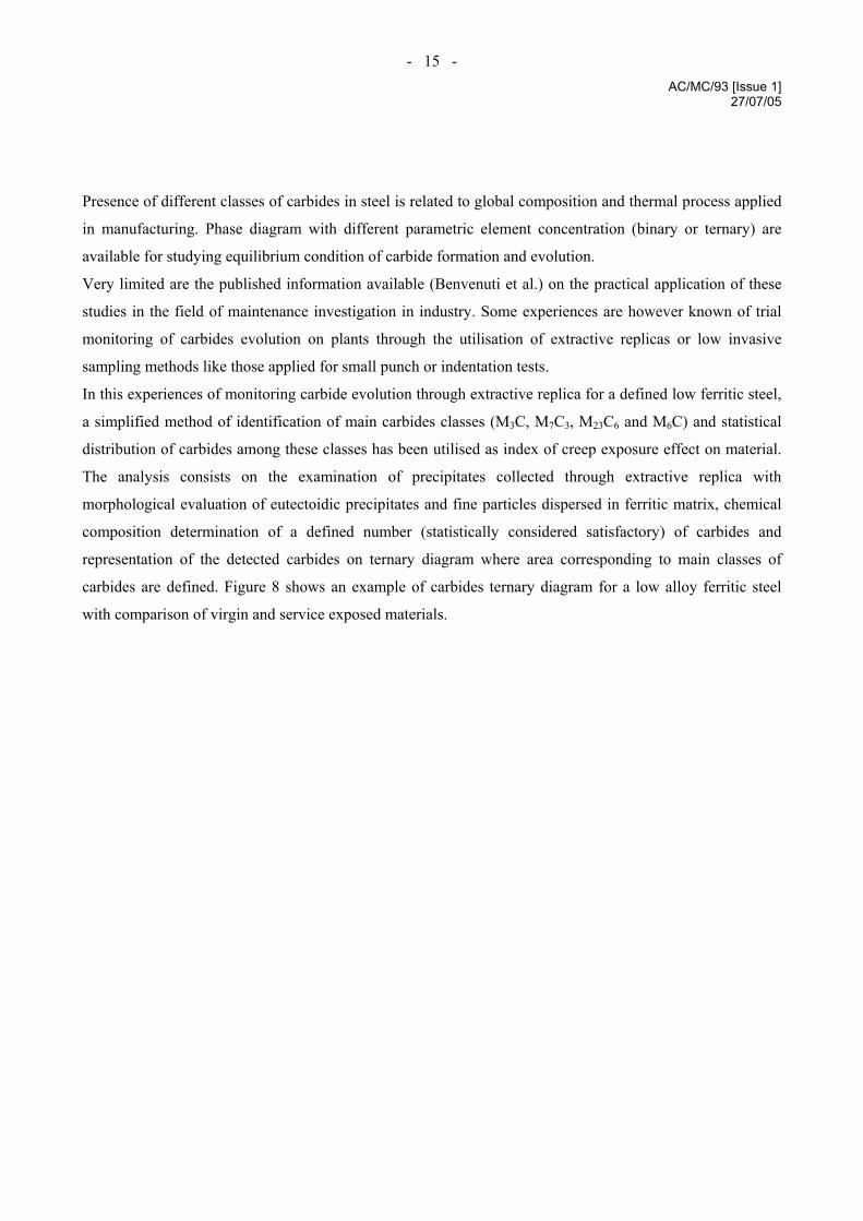
Figure 9 shows in graphical view the results of these studies summarising the two equations and the upper
and lower bound referred to most refined second analysis with a confidence limit 90%.
- 17 - AC/MC/93 [Issue 1]
27/07/05
Figure 9 Cr/Fe ratio in M23C6 carbides and temperature exposure time for P22 material
0.00
0.20
0.40
0.60
0.80
1.00
1.20
1.40
0 10000 20000 30000 40000 50000 60000
Exposure time (h)
Cr/F
e ra
tio in
M23
C6
Data analysis 1Data analysis 2 with upper and lower bound 90% confidence limit
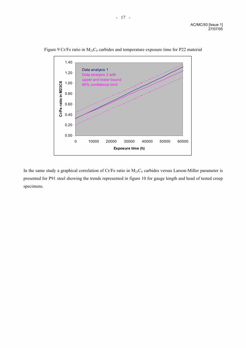
In the same study a graphical correlation of Cr/Fe ratio in M23C6 carbides versus Larson-Miller parameter is
presented for P91 steel showing the trends represented in figure 10 for gauge length and head of tested creep
specimens.
- 18 - AC/MC/93 [Issue 1]
27/07/05
Figure 10 Cr/Fe ratio in M23C6 carbides and Larson-Miller parameter for P91 material
2
3
4
19000 20000 21000 22000 23000
PLM
Cr/F
e ra
tio in
M23
C6
specimen gauge lengthspecimen head
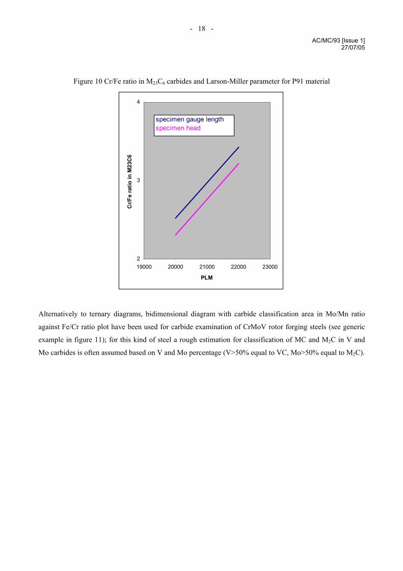
Alternatively to ternary diagrams, bidimensional diagram with carbide classification area in Mo/Mn ratio
against Fe/Cr ratio plot have been used for carbide examination of CrMoV rotor forging steels (see generic
example in figure 11); for this kind of steel a rough estimation for classification of MC and M2C in V and
Mo carbides is often assumed based on V and Mo percentage (V>50% equal to VC, Mo>50% equal to M2C).
- 19 - AC/MC/93 [Issue 1]
27/07/05
Figure 11 Carbide classification graph in bidimensional diagram for CrMoV rotor steel
0
2
4
6
8
10
0 2 4 6 8 10 12 14
Mo/Mn ratio
Fe/C
r rat
io
M7 C3
M3C
M23C6
M6C
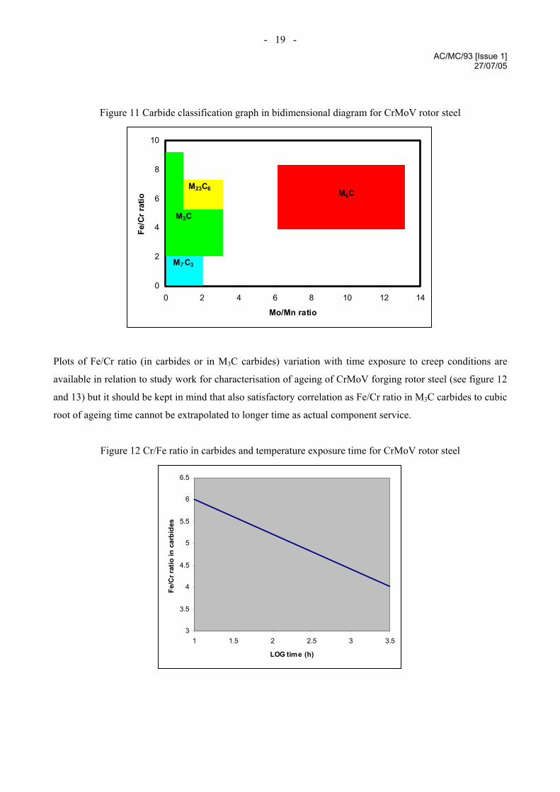
Plots of Fe/Cr ratio (in carbides or in M3C carbides) variation with time exposure to creep conditions are
available in relation to study work for characterisation of ageing of CrMoV forging rotor steel (see figure 12
and 13) but it should be kept in mind that also satisfactory correlation as Fe/Cr ratio in M3C carbides to cubic
root of ageing time cannot be extrapolated to longer time as actual component service.
Figure 12 Cr/Fe ratio in carbides and temperature exposure time for CrMoV rotor steel
3
3.5
4
4.5
5
5.5
6
6.5
1 1.5 2 2.5 3 3.5
LOG time (h)
Fe/C
r rat
io in
car
bide
s
- 20 - AC/MC/93 [Issue 1]
27/07/05
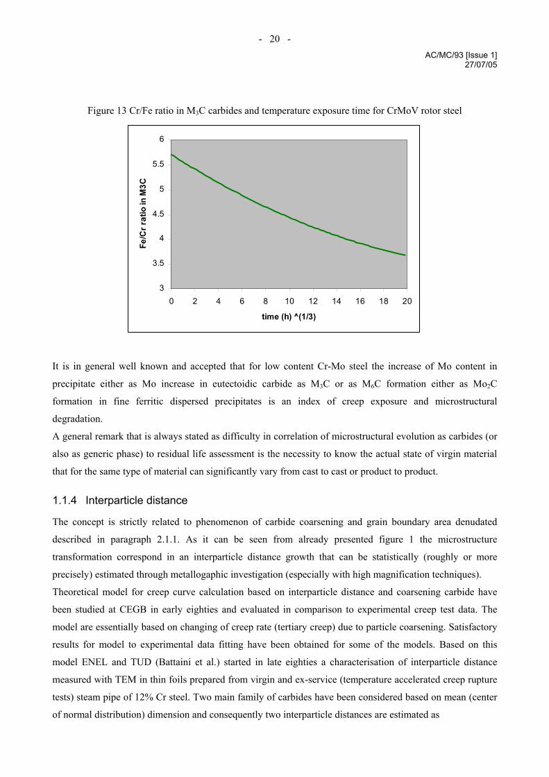
Figure 13 Cr/Fe ratio in M3C carbides and temperature exposure time for CrMoV rotor steel
3
3.5
4
4.5
5
5.5
6
0 2 4 6 8 10 12 14 16 18 20
time (h) ^(1/3)
Fe/C
r rat
io in
M3C
It is in general well known and accepted that for low content Cr-Mo steel the increase of Mo content in
precipitate either as Mo increase in eutectoidic carbide as M3C or as M6C formation either as Mo2C
formation in fine ferritic dispersed precipitates is an index of creep exposure and microstructural
degradation.
A general remark that is always stated as difficulty in correlation of microstructural evolution as carbides (or
also as generic phase) to residual life assessment is the necessity to know the actual state of virgin material
that for the same type of material can significantly vary from cast to cast or product to product.
1.1.4 Interparticle distance
The concept is strictly related to phenomenon of carbide coarsening and grain boundary area denudated
described in paragraph 2.1.1. As it can be seen from already presented figure 1 the microstructure
transformation correspond in an interparticle distance growth that can be statistically (roughly or more
precisely) estimated through metallogaphic investigation (especially with high magnification techniques).
Theoretical model for creep curve calculation based on interparticle distance and coarsening carbide have
been studied at CEGB in early eighties and evaluated in comparison to experimental creep test data. The
model are essentially based on changing of creep rate (tertiary creep) due to particle coarsening. Satisfactory
results for model to experimental data fitting have been obtained for some of the models. Based on this
model ENEL and TUD (Battaini et al.) started in late eighties a characterisation of interparticle distance
measured with TEM in thin foils prepared from virgin and ex-service (temperature accelerated creep rupture
tests) steam pipe of 12% Cr steel. Two main family of carbides have been considered based on mean (center
of normal distribution) dimension and consequently two interparticle distances are estimated as
- 21 - AC/MC/93 [Issue 1]
27/07/05
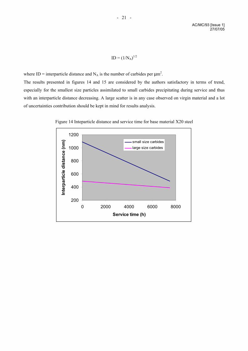
ID = (1/NA)1/2
where ID = interparticle distance and NA is the number of carbides per µm2.
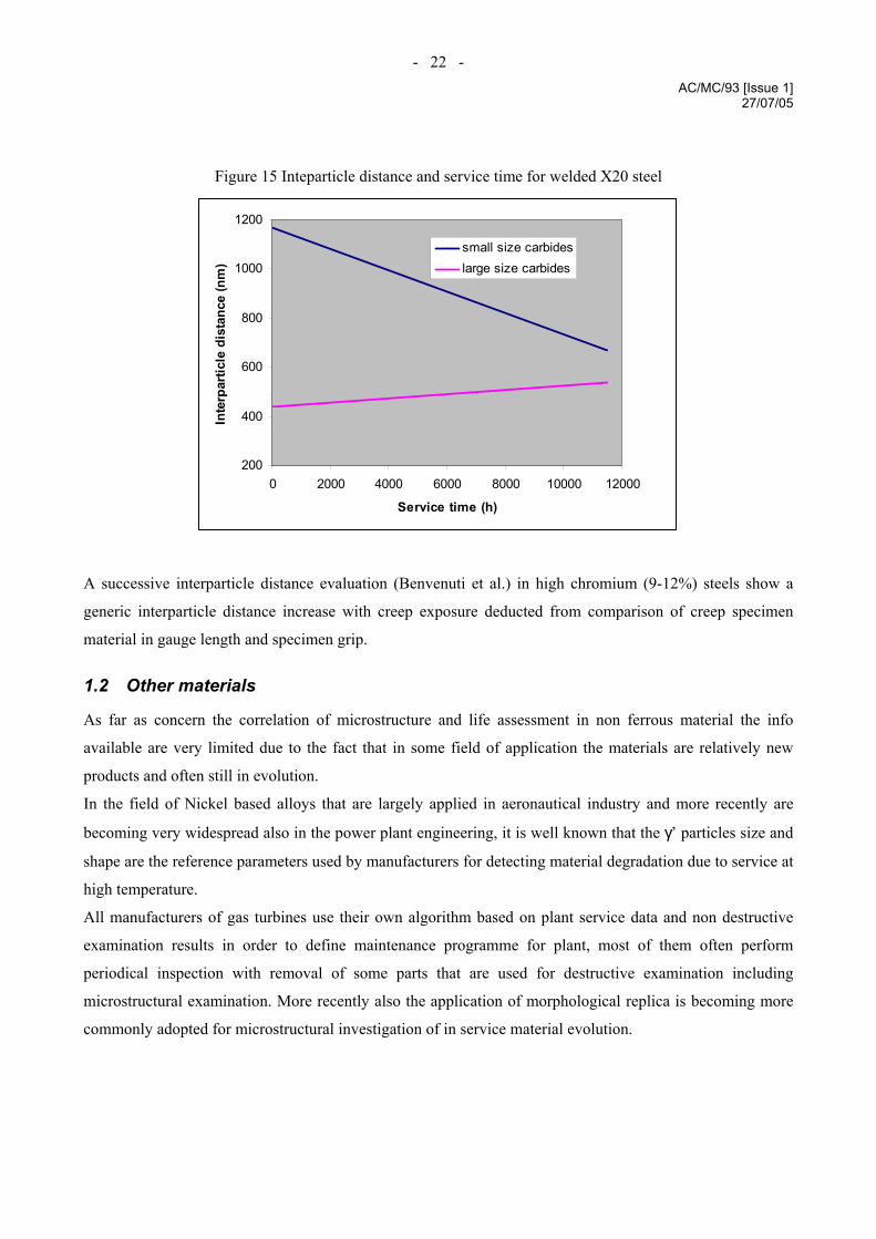
The results presented in figures 14 and 15 are considered by the authors satisfactory in terms of trend,
especially for the smallest size particles assimilated to small carbides precipitating during service and thus
with an interparticle distance decreasing. A large scatter is in any case observed on virgin material and a lot
of uncertainties contribution should be kept in mind for results analysis.
Figure 14 Inteparticle distance and service time for base material X20 steel
200
400
600
800
1000
1200
0 2000 4000 6000 8000
Service time (h)
Inte
rpar
ticle
dis
tanc
e (n
m) small size carbides
large size carbides
- 22 - AC/MC/93 [Issue 1]
27/07/05
Figure 15 Inteparticle distance and service time for welded X20 steel
200
400
600
800
1000
1200
0 2000 4000 6000 8000 10000 12000
Service time (h)
Inte
rpar
ticle
dis
tanc
e (n
m)
small size carbideslarge size carbides
A successive interparticle distance evaluation (Benvenuti et al.) in high chromium (9-12%) steels show a
generic interparticle distance increase with creep exposure deducted from comparison of creep specimen
material in gauge length and specimen grip.
1.2 Other materials
As far as concern the correlation of microstructure and life assessment in non ferrous material the info
available are very limited due to the fact that in some field of application the materials are relatively new
products and often still in evolution.
In the field of Nickel based alloys that are largely applied in aeronautical industry and more recently are
becoming very widespread also in the power plant engineering, it is well known that the γ’ particles size and
shape are the reference parameters used by manufacturers for detecting material degradation due to service at
high temperature.
All manufacturers of gas turbines use their own algorithm based on plant service data and non destructive
examination results in order to define maintenance programme for plant, most of them often perform
periodical inspection with removal of some parts that are used for destructive examination including
microstructural examination. More recently also the application of morphological replica is becoming more
commonly adopted for microstructural investigation of in service material evolution.
- 23 - AC/MC/93 [Issue 1]
27/07/05
2 Techniques applied for investigation on in-service components
The most of the studies done on correlation of material microstructure and creep exposure have been
performed by means of metallographic specimen obtained from creep specimen after tests. A large
improvement of the investigation on actual in service components has been obtained with the replica
technique.
The large success of this technique is correlated to the fact that replica can be assumed as a non destructive
technique or at least very low invasive technique, and this is the first requirement for an investigation applied
for residual life evaluation not affecting the same parameters.
Due to the criticity of weld repair the withdrawal of specimen from in service component is not
recommended as approach for microstructural investigation.
The recently developed technique of small punch sampling that can be assumes as low invasive technique
can be an alternative to replica especially for the wider spectrum of microstructural information that can be
obtained from a massive specimen.
2.1.1 Replica investigation
The technique is essentially the application of metallographic specimen preparation (grinding, polishing, and
etching) to a limited area of the component that is required to investigate and the reproduction of the so
prepared surface on a thin foil of polymeric material.
If microstructure evolution is the target of replica examination, the removal of a thin layer of surface material
(about 0.3-0.5 mm thickness reduction) is recommended so to avoid the external layer of decarburised
material.
The reproduction of prepared surface on plastic material is achieved by the softening of polymeric thin foil
with adequate solvent followed by hardening of the same plastic material due to solvent evaporation.
Replica can be observed with the utilisation of an optical microscope, where standard magnification ranges
from 50 to 500 x ( 1000 x magnification can be achieved but often difficulties can be matched on focus
optimisation of replica surface).
If properly prepared with application of a conductive support and gold thin foil application on reproduced
surface, replica can be observed also with scanning electron microscope achieving the possibility to observe
reproduced microstructure aspect with higher magnification. Replica examination on SEM should be
performed carefully in order to take care that electron beam doesn’t produce any excessive heating of the
surface with possible consequent deformation of plastic material underlaying.
Major limitation of the replica is the necessity to reduce the examined area to a very limited extension if
compared to actual component dimension. The preliminary correct identification of the position in

- 24 - AC/MC/93 [Issue 1]
27/07/05
component that should be replicated is thus a very critical phase, in order to be sure that the replica examined
is representative of the most probabilistic damaged area.
Location of area to be examined by means of replica is usually based on the analysis of plant operating
condition correlated to component design dimensions and material type. Pre-replica measurement of actual
thickness component parts by means of UT is also recommended in order to detect eventually existing
defined area where local corrosion or other actions can cause thickness reduction and consequently higher
stresses with more probabilistic creep damage.
Replica can be prepared mainly on the external surface of components, industrial experience of creep
damages or failure has however showed that in the most cases creep damage is generally most evident in this
area although some cases of internal surface creep damages have been detected.
As already stated although replica is a low invasive technique a limited reduction of thickness is necessary in
replica preparation and this represents thus also a limit for application.
2.1.2 Extractive replica
Following the same procedure of surface preparation used for morphological replica, it is possible to take
from material also extractive replica. Applying a specific etching of the prepared surface oriented to remove
the metal matrix and separate carbides and other precipitates, it is then possible by means of specific time
hardening polymeric resins to remove from material surface the precipitates that can be later analysed with
electron microscope (scanning and transmission). Alternative techniques for carbon extraction replica are
available (not using polymeric resins) but mainly applicable on laboratory specimens (from mechanical or
metallographic testing)
All limitations previously described for morphological replica are in principle extended also to extractive
replica, in addition to these it is very critical for the extractive replica to apply the proper etching that enables
to remove the metal matrix without any perturbation on carbides and other precipitates. The necessity to
examine this replica through electron microscope is an additional limitation due to the difficulty to evaluate
on plant the good quality of produced replica. Preliminary examination by light microscope can give just a
rough idea of replica quality. Examination of extractive replica with scanning electron microscope doesn’t
require any particular additional preparation except than taking care of polymeric resin conductivity. In the
case of transmission electron microscope, the replica sampled in plant should then be prepared for final
examination by transferring the carbides and precipitates from resins (dissolved) to a thin layer of graphitic
carbon. The examination of these replica in transmission electron microscope where the thin samples that
can by analysed are small square foils of a few millimetres size, enhances more than in the previous case the
problems related to representativity of sampling area for component.
- 25 - AC/MC/93 [Issue 1]
27/07/05
3 Hardness
Since the first study developed for the assessment of residual life in high temperature serviced components,
attention has been paid to hardness value in order to find numerical correlation of the parameter with service
and expected time of the component. In the research studies hardness has been measured through standard
instruments as Vickers or Brinell indenter based, but for in plant direct monitoring of serviced component
some instruments based on energy absorption during impact or indentation combined with ultrasonic
measurements are available as correlation for standard unit conversion. Due to this fact it is thus possible to
obtain also results directly from in-service components. Actually at the moment although hardness
measurement in plant is a commonly applied technique during maintenance inspection (especially in
combination with replica) the most of the published studies are based on laboratory measurement made on
test specimens with standard hardness measurement techniques.
Gooch et al. in the already mentioned study relevant to remanent life assessment of rotor forgings evaluated
in addition to microstructural aspect also correlation to hardness remarking that:
• hardness changes with ageing is time, temperature and stress dependent,
• although the confidence limits are very wide, a relationship of hardness with Larson-Miller can be
described,
• hardness decreases with exposure to creep conditions service,
• softening under applied stress is greater than in the case of thermal ageing without stress,
• softening under applied stress is proportional to stress,
• hardness evaluation can be used for estimating true operating temperature but statistical confidence
limits suggests to evaluate results generated from a database carefully case by case,
• hardness evaluation is not a practicable means of estimating the creep rupture strength and ductility of a
previously uncharacterised rotor.
The general proposed equation for hardness changes and life assessment correlation can be espressed as:
Hv/Hv0 = a • PLM + b • PLM2 + c
where Larson-Miller parameter is calculated by
PLM = T • (A + Log t)
“T” is temperature in °K
“t” is time in hours
while a, b, c and A are parameters depending on the assumed database in the following ranges
- 26 - AC/MC/93 [Issue 1]
27/07/05
“a” from 1.25•10-3 to 1.6•10-3
“b” from 3.91•10-8 to 4.97•10-8
“c” from –8.94 to –11.99
“A” from 7.8 to 15.82 as best fit values or 20 as conventional value.
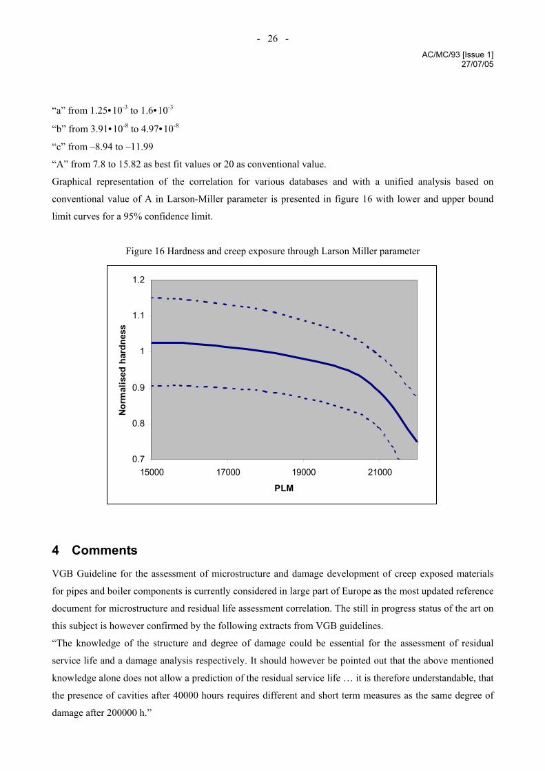
Graphical representation of the correlation for various databases and with a unified analysis based on
conventional value of A in Larson-Miller parameter is presented in figure 16 with lower and upper bound
limit curves for a 95% confidence limit.
Figure 16 Hardness and creep exposure through Larson Miller parameter
0.7
0.8
0.9
1
1.1
1.2
15000 17000 19000 21000
PLM
Norm
alis
ed h
ardn
ess
4 Comments
VGB Guideline for the assessment of microstructure and damage development of creep exposed materials
for pipes and boiler components is currently considered in large part of Europe as the most updated reference
document for microstructure and residual life assessment correlation. The still in progress status of the art on
this subject is however confirmed by the following extracts from VGB guidelines.
“The knowledge of the structure and degree of damage could be essential for the assessment of residual
service life and a damage analysis respectively. It should however be pointed out that the above mentioned
knowledge alone does not allow a prediction of the residual service life … it is therefore understandable, that
the presence of cavities after 40000 hours requires different and short term measures as the same degree of
damage after 200000 h.”
- 27 - AC/MC/93 [Issue 1]
27/07/05
It’s important to remark that all other (but cavities) microstructural observed parameters need to be evaluated
on the basis of the as received material correspondent status in order to avoid any misleading deduction from
generic or recommended microstructure variation not actually correlated to service exposure.
5 Final recommendations
Evaluation of microstructural evolution in exposed to service materials is a key tool for a correct evaluation
of material status and allowable service extension. A reliable life assessment should be made not only by
means of microstructural inspection but it’s preferable that together with other inspections the same is
included. Among the different aspects that can be observed the evaluation of microcavitation presence and
creep damage evolution seems to be, for the widely applied ferritic low alloyed steels, the most consolidated
approach and the evolution of Neubauer classification with subclassification in particular of grade 2 and 3
(that corresponds to the longest part of a component life) should be continued and encouraged. At present it
seems that singular countries are working independently in this field and an essay for a common effort of a
unified revision of Neubauer classification should be welcomed.
For every other microstructural aspect (except microcavities), whatever is the monitored one it is very
important that the evaluation is made by comparison with the original (virgin material) status.
From the view point of the techniques applied for monitoring microstructure on in-service components,
replica are surely a consolidated and reliable technique, attention should be paid in any case also to
alternative low invasive technique for sampling as the ones applied for small punch or impression creep
specimen preparation.
- 28 - AC/MC/93 [Issue 1]
27/07/05
6 Bibliography
1) Microstructural examination of several commercial ½Cr½Mo¼V casts in the as received and service
exposed conditions (K.R.Williams) CEGB research laboratory report 1979
2) Note on VC coarsening in ferritic steels (J.M.Silcock) CEGB confidential note 1981
3) VC coarsening in ½Cr½Mo¼V steel (T.P.Crispin-J.M.Silcock) CEGB confidential note 1981
4) Metallographic examination of ½Cr½Mo¼V creep specimens from ERA project 2021 (M.Askins-
M.S.Shammas-J.M.Silcock) CEGB confidential note 1982
5) Summary of calculations of creep curves from coarsening equations (J.M.Brear-S.Bruce-B.J.Cane-
J.M.Silcock) CEGB research internal document 1982
6) Metallographic techniques for residual life assessment of 1CrMoV rotor forging (J.Maguire-D.J.Gooch)
CEGB unrestriced but not published document 1988
7) Techniques for remanent life assessment of 1CrMoV rotor forging Cavitation assessment (G.Lyell-
A.Strang-D.J.Gooch-J.Maguire-S.M.Beech-W.R.Callender-C.E.Raynor) National Power Confidential
note 1990
8) Techniques for remanent life assessment of 1CrMoV rotor forging Hardness evaluation (G.Lyell-
A.Strang-D.J.Gooch-J.Maguire-S.M.Beech-W.R.Callender-C.E.Raynor) National Power Confidential
note 1990
9) The effect of oxidation specimen size on the creep rupture of low alloy ferritic steels (D.J.gooch-
M.S.Shammas) National Power confidential note 1990
10) Methods for remaining life prediction of steam pipes and boiler tubes (Castani-D’Angelo-Michelizzi /
ENEL) presented at seminar on “Remanent life of high-temperature plants” London UK October 1983
11) Application of image analysis techniques and scanning electron micrsocopy to the study of cavitation in
creep resistant materials (Anelli-Faccenda-Franzoni / Centro sperimentale Metallurgico) Elsevier 1981
12) Microstructure and creep crack growth behaviour in low alloy steels (Airoldi-Bianchi-D’Angelo /
ENEL) presented at International Symposium on “Microstructure and mechanical behaviour of
materials” Xi’an China October 1985
13) Reliability of quantitative metallography approach for material evolution assessment (D’Angelo-Regis /
ENEL; Franzoni /CSM; Rossi/Dalmine) proceedings of Second International Conference on “Creep and
fracture of engineering materials and structures” Swansea UK September 1984
14) How the microstructure affects the high-temperature properties of low-alloy steels strengthened with
vanadium carbide (Prnka /FMRI; Foldyna-Sobotka/RIVS) presented at International Conference
“Properties of creep resistant steels” Dusseldorf may 1972
- 29 - AC/MC/93 [Issue 1]
27/07/05
15) Carbide changes in Cr-Mo-V steels in the course of long service (Bologov-Lanskaya-Bulanov-Tolstov)
published by Thermal Engineering 1981
16) Prediction of service characteristics of steam pipes made of 12Cr1MoV steel after their design service
life (Bologov-Lanskaya-Novitskaya-Rushchits) published by Thermal Engineering 1979
17) Macroscopic measurements of creep damage in metals (Brathe/University of Technology Goteborg)
published by Scandinavian Journal of Metallurgy 1978
18) Role of carbides in low-alloy creep resisting steels (Woodhead-Quarrell / University of Sheffield)
published on Journal of the iron and steel institute 1965
19) Structural integrity assessments and lifetime predictions of operating thermal power pipelines (Billi-
D’Angelo-Maciga-Livraghi /ENEL)
20) Application of Structural Surface Examination for the testing of power plant components subjected to
creep stress (Arnswald/VKR;-Blum/FV-Neubauer/TUV-Poulsen/JTI ) reprinted from VGB
Kraftwerkstechnik July 1979
21) Determinazione del periodo di ulteriore esercibilità prima del successivo controllo per un componente
soggetto a scorrimento viscoso (Fossati-Sampietri/ CESI) seminar in Siracusa I 2001
22) Criteria for prolonging the safe operation of structures through the assessment of the onset of creep
damage using non-destructive metallographic measurements (Neubauer/TUV) reprint from “Creep and
fracture of engineering materials and structures” march 1981
23) R. Viswanathan Damage mechanisms and life assessment of high temperature components ASM
International 1989
24) Metallographic techniques for estimation of residual creep life (Roberts-Ellis-Henry/CE; Askins-
Shammas-Townsend/CEGB; Cane/ERA; Viswanathan/EPRI)
25) Remanent life assessment of process plant (Cane-Bell/ERA)
26) Residual life techniques for plant life extension (Viswanathan-Dooley-Manfred/EPRI)
27) Creep life assessment techniques for fossil power plant boiler pressure parts (Viswanathan-
Dooley/EPRI)
28) Experiences with remanent life evaluation testing (De Witte-Stubbe/Laborelec)
29) Cavitation and rupture life prediction in low alloy ferritic steels (Needham-Gladman/BSC)
30) Microstructural changes in long term aged steels (A.Benvenuti-N.Ricci/CISE D.D’Angelo-
G.Fedeli/ENEL) Microstructures and mechanical properties of ageing material –The mineral, metals, &
materials society 1993
31) Evaluation of microstructural parameters for the characterisation of 2½ Cr 1Mo steel operating at
elevated temperature (A.Benvenuti-N.Ricci/CISE G.Fedeli/ENEL) Proceeding of Swansea conference
1990
- 30 - AC/MC/93 [Issue 1]
27/07/05
32) Interparticle distance evolution on steam pipes 12%Cr steel during power plants’ service time
(P.Battaini-D.D’Angelo-G.Marino/ENEL J.Hald/TUD Lyngby) Proceeding of Swansea conference 1990
33) Evoluzione microstrutturale di acciai 9-12%Cr sottoposti a scorrimento viscoso (A.Benvenuti-
N.Ricci/CISE P.Bontempi/ENEL) La metallurgia italiana 1995
34) Assessment of material thermal history in elevated temperature components (A.Benvenuti-S.Corti-
N.Ricci/CISE P.Bontempi/ENEL) Material characterisation Elsevier science 1996
35) Reliability problems in methods of residual creep life assessment (L.Kloc-V.Sklenicka/IPM Brno)
Proceedings of 10th conference on creep & fracture of engineering materials and structure Prague 2001)
36) Creep properties affected by morphology of MX in high Cr ferritic steels (K.Yamad-S.Muneki-
F.Abe/NMIR M.Igarashi/Sumitomo) Proceeding of Swansea conference 2001)
37) Microstructure change during creep deformation of modified 9Cr1Mo steel (F.Yoshida-D.Terada-
H.Nakashima/Kyushu university H.Hayakawa/Kyushu electric power S.Zaefferer/TU Darmstad)
Proceedings of Swansea conference 2001
38) The use of light and electron microscope investigations to characterise the creep behaviour of welded
joints in modern power station materials (E.Letofsky-H.Cerjak-I.Papst-P.Warbichler/Graz University)
Proceedings of Swansea conference 2001
39) Linee guida per la valutazione di vita residua per componenti in regime di scorrimento viscoso ISPESL
(Istituto Superiore per la Prevenzione e la Sicurezza del Lavoro) Circ. 48/03
40) Critical stress for transition of creep deformation behaviour in virgin and long serviced material of
2.25Cr-1Mo steels (T.Ohba, E.Baba, K.Kimura, F.Abe, K.Yagi/NIMS; I Nonaka/IHI) Proceedings of
the 6th international Charles Parsons turbine conference
41) Reliability assessment of 2.25Cr-1Mo steel after prolonged exposure in plant (T.Ohba, E.Baba, F.
Abe/NIMS; I.Nonaka IHI) 27th MPA-Seminar 2001
42) A cost effective maintenance approach for a steam system subject to creep conditions (H.J. Bouwman,
A. Helkoop) International Conference “Life Assesment and Extension” 13-15 June 1988
43) Optimisation of lifetime of creep loaded structures – Results of projects of the Netherlands Institute of
Welding (C.F. Etienne, J. Prij) International Conference “Life Assesment and Extension” 13-15 June
1988
44) Utility survey and inspection for life assessment of elevated temperature headers (Roberts-Ellis/CE;
Viswanathan/EPRI) American Power conference