Residential Stormwater Management - swrcb.ca.gov · Library of Congress Catalog Number: LC75-34759...
63
& design considerations published jointly by ULI-the Urban Land Institute ASCE-the American Society of Civil Engineers NAHB- the National Association of Home Builders
Transcript of Residential Stormwater Management - swrcb.ca.gov · Library of Congress Catalog Number: LC75-34759...

& design considerations published jointly by ULI-the Urban Land Institute ASCE-the American Society of Civil Engineers NAHB- the National Association of Home Builders
About the Publishers
ASCE—the American Society of Civil Engineers NAHB-the National Association of 345 East 47th Street Home Builders 1200 18th Street, N.W. New York, New York 10017 15th and M St., N.W.
Washington, D.C. 20005 The American Society of Civil Engineers was the first na- tional engineering society to be established in the United The National Association of Home Builders of the United States. Founded in 1852, ASCE’s objective is the “ad- States is a professional trade organization representing vancement of the science and profession of engineering.” the bulk of the housing industry. It has more than 75,000
members in some 580 affiliated local and state associa- tions in the United States and Puerto Rico and 43 interna- The American Society of Civil Engineers has 70,000 tional affiliates. members. Membership is held by individual engineers
and other qualified individuals. Membership qualification standards are high and each year as many as 8% of the As the “Voice of America’s Housing Industry” NAHB pre- applications for membership are declined and several sents the industry’s views to the Administration, to Con- hundred members are dropped because they have not gress, and to government housing agencies. It offers its
grade of society membership. The maintenance of high ing operations, from land use to cost data, from marketing standards has resulted in a distinguished membership to construction techniques. and makes the activities of the Society particularly signif- Headquarters for the NAHB is the National Housing
Center in Washington, D.C. icant.
ASCE operates on a budget of more than $5 million with almost one-half of this amount spent for publications. En- trance fees and dues make for half of the Society’s in- come with the rest coming from publication sales, adver- tising, and investments.
ULI—the Urban Land Institute
Washington, D.C. 20036
ULI—the Urban Land Institute is an independent, non- profit organization incorporated December 14, 1936 to improve the quality and standards of land use and de- velopment.
The lnstitute is committed to conducting practical re- search in the various fields of real estate knowledge; identifying and interpreting land use trends in relation to the changing economic, social and civic needs of the people; and disseminating pertinent information leading to development of land.
and sale of publications and contributions for research
advanced their professional qualifications to a higher members advice and guidance on every phase of build- ULI receives its financial support from membership dues
and panel services.
©1975 by ULI—the Urban Land Institute. NAHB-the National Association of Home Builders, ASCE—the American Society of Civil Engineers. All rights re- served. Reproduction or use of the whole or any part of the contents without written permission of the copyright holder is prohibited. Printed in the United States of America. Library of Congress Catalog Number: LC75-34759

ABOUT THE PUBLISHERS 2 ACKNOWLEDGMENTS 4 FOREWORD 5 INTRODUCTlON 7 OBJECTIVES 15 PRINCIPLES 18 DESIGN CONSIDERATIONS 24 Storm Water Runoff Analysis Considerations 24
Storage Considerations and Criteria 32
Streets and Curbs 37 Natural Drainage 42 Underground Pipe Systems 47
Storm Water Inlets 54 Other Design
Considerations 53 Legal Implications 60
REFERENCES 63 INDEX 64
Acknowledgements An undertaking such as this required the cooperative participation by a significant number of representa- tives from each of the organizations. The need for a report on residential storm water management origi- nated in the NAHB Land Use and Engineering Committee in 1971. An initial survey and interim report completed in 1973 by the NAHB Research Foundation and its staff was the basis for initiation of the joint effort among NAHB, ASCE and ULI. This initial effort was reviewed by each organization. As a result of that review, a revision was prepared by Carl F. lzzard under a grant from the Urban Land Research Foun- dation. This revision was then reviewed by the committees of NAHB, ASCE & ULI; a further draft, including a discussion of legal implications by Ruth M. Wright of Boulder, Colorado, was prepared with the partici- pation of staff members from NAHB, ULI and the NAHB Research Foundation. The draft was further re- viewed and modified with additions from members of the ASCE review committee. Special acknowledge- ment needs to be given to the Urban Water Resources Research Council of ASCE, especially Messrs. Iz- zard, Jens and Jones, for providing leadership and counsel as well as a testing ground for the concepts set forth in this report. Without the willing and diligent participation of all those involved, this joint effort could not have been brought to fruition.
ASCE NAHB ULI S.W. Jens, Chairman, Clayton, Missouri William J. Bauer, Chicago, Illinois W.H. Espey Jr., Cambridge, Massachusetts Brendan M. Harley, Cambridge, Massachusetts Carl F. Izzard, Arlington, Virginia D. Earl Jones Jr., Arlington, Virginia Murray B. McPherson, Marblehead, Massachusetts Charles A. Parthum, Boston, Massachusetts Lincoln W. Ryder, Boston, Massachusetts J.P. Riley, Logan, Utah John B. Stall, Urbana, Illinois Donald C. Taylor, Littleton, Colorado Richard F. Thomas, White Plains, New York Harry G. Wenzel, Urbana, Illinois Kenneth R. Wright, Denver, Colorado Ruth M. Wright, Denver, Colorado G.K. Young, Springfield, Virginia
Land Development Committee Boris S. Lang, Chairman 1975 Vice Chairman 1974-1975 Chairman Development Standards Subcommittee 1973-1975 Robert C. Findlay, Chairman 1973-1975 Chairman Development Standards Subcommittee 1972-1973 Jay Janis, Chairman 1971-1972 Bruce Plunkett, Assistant Chairman 1974-1975 Vice Chairman Development Standards Subcommittee 1973 David P. Rhame, Chairman 1972-1973 Chairman Development Standards Subcommittee 1971-1972 Richard F. Sutherland, Vice Chairman 1973-1974 George S. Writer, Vice Chairman 1971-1973
NAHB Staff Milton W. Smithman, Staff Vice President, Builders Services Rochell Brown, Jr., Assistant Director Land Use Development
NAHB Research Foundation Robert Arquilla, Chairman Research Institute Board of Trustees 1971-1973 Robert F. Schmitt, Chairman Research Institute Board of Trustees 1973- William A. Watkins, Associate Civil Engineer Donald Luebs, Director of NAHB Sponsored Research
D. David Brandon, New York, New York R.T. Crow, Lake St. Louis, Missouri Buford M. Hayden, Bethesda, Maryland William B. Rick, San Diego, California David K. Sunderland, Colorado Springs, Colorado Leon N. Weiner, Wilmington, Delaware K. Tim Yee, Honolulu, Hawaii
ULI Staff Frank H. Spink, Jr. Director Technical Publications Division Deborah B. Silberman, Editor Robert L. Helms, Production Manager Carolyn E. Noe, Art Director Sarah V. Lantz, Production Assistant

Foreword Publication of this report under the joint auspices of the American Society of Civil Engineers, the National Association of Home Builders and ULI—the Urban Land Institute is a continuation of the unique coopera- tive effort which resulted in a previous jointly sponsored publication, Residential Streets: Objectives, Prin- ciples, and Design Considerations. This report is a second jointly sponsored and reviewed report which represents the attitudes and concerns of the three organizations on a subject of common interest and importance—the setting of objectives, principles and design considerations to be applied to the de- velopment of storm water management systems to serve residential communities.
The content of this report evolved, as did its predecessor, from an assessment of current practices to a guide toward a more creative and thoughtful approach to storm water runoff management. While not re- jecting past practice, it clearly identifies and articulates a new underlying philosophy and approach which diverges significantly from the past.
It is hoped that this report will stimulate communities of all sizes, in all locales, to rethink current storm water management practices and to adopt those which are responsive to local conditions and supportive of the basic objectives and principles presented herein.
Eugene Zwoyer Executive Director American Society of Civil Engineers
Nathaniel Rogg Executive Vice President NAHB-National Association of Home Builders
David E. Stahl Executive Vice President ULI—the Urban Land Institute.

INTRODUCTION
The Need for Change The basic philosophy of storm water management in residential, and for that matter, all kinds of develop- ment, is open to challenge and revision. Nationwide experience with the effects of narrow and inadequate philosophies on past practices indicates that storm water has rarely been well managed, and has in fact often been mismanaged. To some extent, at least in residential developments, past approaches, de- velopment patterns and public policies inadvertently encouraged the very approaches this report seeks to modify. Simply stated, past philosophy sought max- imum convenience at an individual site by the most rapid possible elimination of excess surface water after a rainfall and the containment and disposal of that water as quickly as possible through a closed system. The cumulative effects of such approaches have been a major cause of increased frequency of downstream flooding, often accompanied by di- minishing groundwater supplies, as direct results of urbanization; or have necessitated development of massive downstream engineering works to prevent flood damage. The downstream urban flooding prob- lem has become acute during the past thirty years as communities have grown and as curbed roadways (paved channels) have been installed in both new suburban areas and throughout older areas that formerly provided runoff-retarding storage in road- side swales or ditches. Amelioration of the unfortu- nate results of past urbanization requires very large investments to construct additional flood control works. Where flood control is infeasible, the flooding hazard reduces property values and may lead to abandonment, which is unacceptable to community leaders.
7
The entire process of storm water runoff management is currently undergoing a significant redirection, if not a revolution. This is evidenced by a new em- phasis on the desirability of detaining or storing rainfall where it falls, on-site, which sometimes re- quires tradeoffs with short-term localized incon- venience. These kinds of solutions applied to indi- vidual sites or developments often have beneficial cumulative effects by attenuating both peak runoff and total short-term runoff. If fully applied throughout a drainage basin, they would reduce major facilities investments required to protect against flood haz- ards in the lower portion of the drainage basin.

The Problem
In an undeveloped area, the storm water manage-
with rainfall-the storm. Some of the water stands where it falls on leaf or plant, and evaporates; some is absorbed into the ground near the surface and feeds trees and plants, ultimately to be returned to the atmosphere by transpiration; some percolates deeply into the ground and replenishes the ground- water supply. The remainder gradually or quickly collects into rivulets, accumulating both in quantity
drainageways and streams to its ultimate desti- nation—the river and then the sea, to begin the cycle again (Figure l ) .
All of us have been exposed to this simple explana- tion but its seeming simplicity belies its complexity. Nature’s inability to accommodate severe storms without significant damage, even where urbanization has not occurred, is quite apparent. The natural drainage systems in an undeveloped area are not static in design, but are constantly changing. Streams change course, banks erode, vegetation and soil permeability change with seasons, lakes fill in with sediment and disappear. The stripping of ground and tree cover by fire may change an entire system, forcing new natural accommodations throughout the system. Urbanization has required new drainage systems because man was both unwill- ing to suffer inconvenience where it could be avoid- ed and because he would not tolerate the loss of life or property. In an urbanizing area, those concerns often have been translated into storm water man- agement system requirements for convenience and safety, without recognition of other significant con- siderations. This has meant that no matter how large the rainfall or its duration, the drainage system was expected to remove runoff as quickly as possible, to
restore maximum convenience in the shortest possi- ble period of time. At the same time, fears of loss of life and of damage to possessions have encouraged
storm that nature might generate.
It is the premise of this report that these two objec- tives are not mutually achievable without extremely high “cost”. Where we have sought maximum con- venience as our first choice in the upper and middle reaches of a watershed, we have created imbal- anced systems, and increased hazard and risk of
ous -to strike a realistic balance between elimina- tion of inconvenience and protection against hazard, Past practice has not always achieved such a bal- ance. In fact, it more often than not has encouraged acceleration of imbalance as areas urbanized.
a ment system is provided by nature. The cycle begins a search for 100 percent protection against the worst
and speed as it hurries down the watershed through damage along the lower reaches. The need is obvi-

Figure 1 Hydrologic Cycle

New Development Patterns Provide New Opportunities
Every parcel of land is part of a larger watershed. Ideally, a storm water runoff management solution for each development project should be based on, and supportive of, a plan for its entire drainage basin. This is not a revolutionary idea, but only recently have data collection and data handling technology made this economically possible in a meaningful way. Even in the absence of such basin-wide plans, new approaches to residential land planning, which have been evolving since about 1955, have made it possible to apply more creative approaches to storm water management within a project. 43, 49 With their application, the net effects of incremental urbaniza- tion can avoid most negative impacts and may pro- duce benefits, enhancing opportunities for future im- plementation of an overall basin-wide drainage plan.
Before 1945, most residential development involved small parcels of land and often proceeded on a lot- by-lot basis. Development was easily accommo- dated using the then-prevalent philosophy of maxi- mum convenience and rapid downstream disposal of surface water. The pace of urbanization was slow and the cumulative impact of drainage decisions was difficult to assess, if it was even considered.
The major residential boom in the post 1945 era, re- lying on total subdivision of land into individual lots, often with complete stripping of natural site features and replacement by an “efficient” design, was the logical extension of that approach. Beginning in the late 1950’s, however, some proposed residential de- velopments clustered dwellings and created com- mon open space, seeking to preserve and enhance natural site attributes. These various innovative con- cepts of land planning, which have now become grouped under the common title Planned Unit De- velopment present opportunities for storm water management consistent with the emerging new phi- losophy advocated by this report. Traditional sub- division design practices will also benefit from the new storm water management approaches, but not always to the same degree.
10
Note: Reference numbers shown at various points in the text refer to references provided on page 63 of this report.

11 The Basic Concepts
It is almost impossible to summarize the develop- ment of this report into a concise series of statements of objectives, principles, and design considerations. The ideas are far reaching and deal with many levels of concern. Following, however, are at least some of the basic concepts upon which these principles and objectives are built.
The water falling on a given site should, in an
Among the new trends in basic philosophy that should be pursued, are concurrent recognition of the convenience drainage and overflow or flood conveyance elements of drainage systems, the use of on-site detention storage and “blue-green” 18
development, the increased use of storage to bal- ance out handling or treatment of peak flows, the use of land treatment systems for handling and disposal of storm water, and perhaps most impor- tant a recognition that temporary ponding at vari- ous points in the system, including on the indi- vidual lot, is a potential design solution rather than a problem in many situations.
A continuing recognition that there is a balance of responsibilities and obligations for collection, storage and treatment of storm water to be shared by individual property owners and the community as a whole. A new recognition that storm water is a component of the total water resources of an area which should not be casually discarded but rather should be used to replenish that resource. Storm water problems signal either misuse of a resource or unwise land occupancy.
A growing emphasis on the recognition that every site or situation presents a unique array of physi- cal resources, occupancy requirements, land use conditions, and environmental values. Variations of such factors within a community generally will require variations in design standards for optimal achievement of runoff management objectives.
The above key concerns, while not all-inclusive, em- body a basic philosophy that should receive wide dissemination and due consideration. Although this
ideal design solution, be absorbed or retained on-site to the extent that after development the quantity and rate of water leaving the site would not be significantly different than if the site had remained undeveloped. This objective may con- flict with present statutory and case law in some locales, which does not reduce its validity.
Optimum design of storm water collection, storage and treatment facilities should strike a balance among capital costs, operation and maintenance costs, public convenience, risk of significant water-related damage, environmental protection and enhancement, and other community objec- tives. The optimum balance among these factors is dynamic, changing over time with changing physical conditions and value perceptions.
Just as the importance of water quality is being in- creasingly recognized, a major new emphasis needs to be placed on the identification and ap- plication of “natural” engineering techniques to preserve and enhance the natural features of a site. and to maximize economic-environmental benefit. “Natural” engineering techniques are those which capitalize on and are consistent with natural resources and processes. Engineering de- sign can be used to improve the effectiveness of natural systems, rather than negate, replace or ig- nore them.

12 report focuses primarily on residential design prac- tices, these concepts should be considered and applied to entire drainage basins in which any de- velopment may proceed. Therefore, underlying the points made above is another basic idea that is al-
Reevaluation of the approach to basin-wide runoff management is a universal need. It is the respon- sibility of, and should be an objective of, the pub- lic sector.
Responsible solutions for individual developments in the absence of basin-wide plans will be more dif- ficult to achieve particularly where current practices are based on traditional drainage concepts. For example, if current practices allow upstream devel- opment to use traditional drainage approaches that increase runoff, a development relying on new con- cepts might be unable to accommodate the amount of excess runoff thereby generated without additional significant costs. The approaches suggested herein should allow development to proceed on individual projects in the absence of a basin-wide plan since the strategy for retention and attenuation of peak runoff and total runoff to values not significantly dif- ferent from predevelopment levels would normally be compatible with any future plan that might evolve for a watershed. Unfortunately, this can probably only be achieved at an initially higher cost for the project. Therefore, development of basin-wide plans should be pursued.
A Note for Readers
An area of concern as complex as that of storm water management defies translation into simple terms that would be easily and completely understandable by all the audiences to whom this is addressed. It would be misleading not to have included a significant amount of technical material, which will be of more specific value to engineers attempting to apply the concepts embodied herein, but which may confuse and cloud the understanding of the less initiated reader. To the greatest extent possible, Objectives and Principles and to a lesser extent Design Consid- erations are described in a manner that will achieve general comprehension without ignoring the com- plexities and technical concerns. At the same time, there are significant amounts of technical information and references which can be useful to the engineer seeking to apply this report in actual practice.
Like all documents seeking to serve a wide audience but dealing with technical terms that have of neces- sity acquired very precise meanings for use in de- sign formulae, the participants in the preparation of this report are very concerned about the choice of words and the definition of terms. The obvious temp- tation when trying to espouse new thinking is to es- tablish new and never before used nomenclature. Even the use of the word storm can be questioned because it does not clearly define the true nature and complexities of natural events, each of which is unique. The term “storm” is often applied to synthetic events that for convenience are used in derived equations that sometimes approximate real events.
This report prefers to avoid such precise definitions during general discussion and to accept them, of necessity, when they are part of a technical discus- sion. This dichotomy will be more apparent to the technically trained reader than to the non-technical audience.
ready well perceived and that is being implemented:

13 A Definition of “Storm Water Runoff System”
The term “storm water runoff system” is used fre-
First of all, a storm water runoff system is composed of both natural and man-made elements. In the past, designers have often failed to capitalize upon natural elements and have at times ignored them when a constructed element was installed.
Secondly, these components include not only those which contain and convey storm water, but also those which absorb, store and otherwise use storm water rather than dispose of it.
tem having two purposes: (1) the control of storm water runoff to prevent or minimize damage to prop- erty and physical injury and loss of life which may occur during or after a very infrequent or unusual
or minimize inconvenience or disruption of activity as a result of runoff from more frequently occurring, less significant storms. Some individual components of the drainage system may operate only in fulfill- ment of the first purpose. This dual purpose is characterized in much of the technical literature as “major” and “minor” functions. 18, 29 Many American and foreign cities have revised their drainage design approaches to embrace the dual function approach.
Fourthly, within a single system, there are compo- nents that are designed primarily to obtain conveni- ence at the smallest scale of the system at the indi- vidual site or intersection, during minor or frequent storms. During an infrequent or major storm, the capacities of many of the convenience-oriented components will be exceeded and flow capacity must be provided by other components designed to
provide safety and minimize damage throughout the system, from the individual site to the discharge point of the drainage basin or watershed. It must be
runoff system, subjected to an infrequent major storm, cannot be expected to prevent inconvenience and minor property damage. A design that would eliminate all such stress would be fundamentally un- reasonable and almost certainly infeasible. Expected damages from such a major runoff event would in- clude minor erosion and scour, damage to lawns and vegetation, and damage to unwisely located struc- tures, but flooding or undermining of buildings or es- sential facilities should not occur.
tion expenditures have been for small pipes and in- lets that cannot intercept and transport the total run- off volume from infrequent storms. The designer’s at- tention should focus upon controlling and safely rout-
not find its way into storm sewer pipes. Such a focus often will lead to wiser land occupancy practices, and minimize expensive drainage works construc- tion, while mitigating potential damages from runoff.
quently and will be used herein, as described below. recognized and emphasized that a total storm water
Thirdly, the storm water runoff system is a single sys- Most of our Nation’s past urban drainage construc-
storm; and (2) the control of storm water to eliminate ing all foreseeable runoff, especially that which can-
14 Using This Report
In the next 25 years, more money may be spent for. storm water management than has been spent for drainage during the entire history of the Nation. This will amount to billions of dollars, not including funds that will be expended to maintain water quality, which also is an increasing national concern. Much, if not most, of this investment will be private funds expended during the development of land for urban uses. Ultimately, however, all costs (capital, debt and maintenance) are borne by all citizens. Public in- vestments should be made wisely in furtherance of the quality of life so highly valued. It is the opinion of ASCE, NAHB, and ULI that the application of the Ob- jectives, Principles, and Design Considerations con- tained in this report, with due regard for unique and particular circumstances and conditions found in various areas of the country, will be a significant step in the right direction.
For the concepts in the report to achieve wide appli- cation there will be a need to induce institutional changes even beyond the design professions and the regulatory institutions of governments. Changes also are necessary in the financial institutions which fund development based on their approval of a proj- ect's design, in the insuring institutions and their perceptions of the insurability of this approach, and in the legal professions in relationship to the pre- existing body of land use law regarding rights, re- sponsibilities and liabilities. The implication of the above statement, that change may be precluded by institutional constraints, is real. The importance of encouraging application of worthwhile new ap- proaches should provide the impetus to achieve necessary changes.
It is hoped that this report will motivate creative re- thinking and updating of drainage design practices. Anyone disagreeing with any part of this report is encouraged to advise the publishers of that dis- agreement, including their detailed reasons and al- ternative recommendations. Such information will help guide future revisions and enhance the docu- ment's value to our Nation.

15 OBJECTIVES To provide a clear understanding of residential storm water runoff systems, including their intended functions and the impacts of alternative philosophies or policies on the design and effectiveness of storm water runoff systems.
Residential storm water runoff systems must fulfill two objectives: (1) they must prevent significant loss of life and property due to runoff from any foreseeable rainfall event; (2) they must provide an acceptable degree of convenient access to property during and following fre- quent rainfall events. Both of these objectives must be accommodated in the design process with the under- standing that some protection components of the storm water runoff system may have to operate only in- frequently. It must also be understood that providing protection against a given event, e.g. against the worst storm water runoff of record, does not guarantee that a greater runoff event will not occur during the useful life of the property. Similarly the enlargement of storm water runoff system components providing access conveni- ence is generally an infeasible approach to fulfillment of property protection objectives.
Residential storm water runoff systems are not restricted in their design or impact to the immediate tract of land which they serve Each is a part of a basin-wide drain- age system and must, at a minimum, accommodate storm water flowing into the tract from upstream sources and mitigate the impacts of the outflow on downstream properties.
To a large degree it is only in recent years that the cumulative impact of subdivision drainage in a basin has been assessed with a concern for basin-wide runoff management.
To promote a philosophy for the design of residential storm water runoff systems which an- ticipates the impact of alternative design solutions within both the land subdivision and the overall drainage basin.
To provide a methodology for determining the type and degree of analyses necessary to derive the optimum design solution.

16 To provide guidance toward identification and selection of alternative solutions to drain- age problems which utilize and preserve, to the extent possible, desirable existing natural systems.
This has led some local ordinances to require that storm water runoff rates after development not exceed pre- development runoff peaks, both to aid in erosion control and to decrease the probability of downstream flooding. This goal rarely is fully attainable.
To encourage the design of systems which will minimize potential erosion and sedimenta- tion problems.
To encourage the design of systems which respond to the need to maintain or enhance ground water resources, including ground water quality, except where land stability might be impaired.
Practices suggested herein should not increase lo- calized capital costs for development of quality storm water systems. They should reduce cumulative downstream drainage construction costs by comparison with the effects of past practices that forced rapid runoff from land developments. The suggested practices are not new but their optimum implementation often re- quires reevaluation of the basic philosophy of storm water runoff system design. Changes in philosophy may produce additional alternatives for design solutions which this document may not cover. It is hoped that ad- ditional alternatives will achieve the primary goals of safety, economy and the enhancement of residential environments
To encourage the design of systems which will reduce capital and environmental costs to the community.

17 To encourage the design of systems which will minimize potential pollution from residen- tial surface drainage.
To encourage system designs which conserve materials.
To encourage continuing development of additional methods and practices designed to enhance storm water management contributions to life and environmental quality.
To encourage continuous improvement of regulatory practices and policies, at all levels of government.
To summarize recent advances in practice for the benefit of professionals not routinely in- The design of residential storm water systems can utilize various methodologies to arrive at solutions or al- ternatives for the drainage plans. Differences in runoff management philosophies and in environmental condi- tions should be carefully evaluated in selecting methodologies to be used. The scale of development and the size and physical characteristics of the drain- age area affect selection of methods, as do climatic characteristics. While certain methods may be desir- able for assessing small sites with simple drainage pat- terns, they may be inappropriate for larger sites with more complex patterns. Conversely, the methods avail- able for assessing large scale or basin-wide storm water systems may be too complex, costly and/or ineffi- i- cient to be useful for smaller sites, and often fail to con- sider important micro-scale details and alternatives. No one method or solution is possible for all areas. This document will suggest some logical methods of analysis for selection of optimum localized approaches to storm water management. Inherent in the philosophy regarding those choices is the basic need for practical conservation of natural systems while providing for safety and convenience in land development.
volved in drainage design.

PRINCIPLES General
Local government should study and develop master plans for each drainage basin within its jurisdiction which may be impacted by development. Optimally, contiguous com- munities will collaborate to master-plan drainage basins that extend across jurisdictional boundaries.
18
Future problems can be minimized or avoided if all political jurisdictions within a drainage basin collabo- rate to define and implement optimum analytical meth- odologies, standards and regulations pertaining to drainage systems and land development. 5 1
All individual land development proposals should include storm water runoff system plans that will be compatible with any basin-wide master drainage plans, and that anticipate and provide for potential effects of upstream development on the proposal area and on downstream areas.
The design of a storm water system must consider con- venience and safety both at the subdivision level and at the drainage basin level. Cumulative basin-wide effects of proposed land development practices should pro- vide the basis for decision-making, rather than the gen- erally minimal incremental effects of individual land de- velopments.
Storm water runoff systems should be designed to assure provision of both major and minor components which will serve specific access convenience and property protection objectives.
19 Storage
The design of permanent and temporary ponding and/or storage should be an integral part of the overall development planning process, and should consider opportunities within the open space and landscaped areas for the creation of such facilities.
When provision of storage is being considered, the de- signer should verify that attenuation of the runoff peak will not aggravate any potential downstream peaking conditions.
Storm water runoff systems should be designed to facilitate aquifer recharge when it may be advantageous to compensate for ground water withdrawals. Conversely, designs should avoid recharge where groundwater effects might be harmful.
Design of permanent storage facilities should consider safety, appearance, recreational Storage should not be created by happenstance or strictly in response to aesthetics. Storage must be ra- tionally planned to accomplish its intended functions. Improperly located storage may create its own flooding problems or aggravate others.
use and effective, economical maintenance operations, in addition to the primary storage function.

Open Channels
Natural overland flows, and open channel and swale routings should be the preferred
20
Open channels and swales should harmonize with the natural features of the site. They should relate closely to individual lots so that occupants will not be tempted to use them for disposal of lawn clippings or other debris or wastes. Provisions must be made for maintenance on a routine basis to assure that open channels can func- tion at or near design capacity. The utilization of open
come depositories for debris if installed in neighbor- hoods not having a strong pride of ownership. The blue-green approach can help make a channel into an aesthetic focal point and discourage its abuse.
alignments for major components of a residential drainage system.
channels must be carefully evaluated. They may be-
Open channels and swales should be routed and designed to avoid or minimize safety hazards.
Generally, street and lot patterns and grades should be designed around natural drainage routings, if excessive land development expenses are to be avoided and en- vironmental values preserved and enhanced.
Alignment of open components of a drainage system must be coordinated with the design of lot and street patterns and grades.
Streets and Curbs
Storm water management systems, street layout, lotting patterns, and the horizontal and Residential streets may be broken down into five clas- sifications which may be utilized in the determination of safety and convenience associated with storm drainage considerations. 34 Each of the five classes — place, lane, subcollector, collector and arterial -has its own limitations on the depth of flow in gutters and spread of water across the pavement. Arterial streets should re- main as free of water as is practical. The incidence of high traffic volumes and speeds and probable pedes- trian traffic preclude any appreciable spread of water from the standpoint of both safety and convenience.
vertical locations of curbs, inlets and site drainage and overflow swales should be concur- rently designed.

21 The depth of flows in gutters and the allowable spread of water across the pavement Depth and velocity of runoff flows in the gutters (if any)
on places and lanes must be given careful considera- tion due to the likely presence of children shortly after the end of the rainfall. Prudence suggests that safe ve- locities for pedestrians, especially small children, will be substantially less than ten feet per second.
should be consistent with the classification of the street based upon its anticipated use and traffic load.
Appreciable amounts of runoff usually should not be permitted to flow across an intersec- tion under normal rainfall conditions.
The maximum velocity of flow, in the deepest part of the gutter under “convenience” de- sign conditions, should not exceed ten feet per second.
Storm Water Inlets
The number and spacing of inlets should be carefully regulated. Consideration should be given to: 1. Inlet hydraulic capacities as limited by gutter gra-
dients and cross sections. 2. Peak flow and time of concentration. 3. Erosion, debris and potential inlet blockage.
Inlet design should consider pedestrian and bicycle safety as well as hydraulic efficiency. Grated inlets will generally prove more hazardous and more subject to debris blockage than properly de- signed side-opening inlets.
Sediment traps should not be designed into the inlet box. Inlet boxes should be self- scouring, even under low-flow conditions.

Enclosed Systems
Enclosed components of a storm water runoff system should help manage storm water, not
22
The use of enclosed components should be minimized to the extent consistent with (1) the ability of the existing natural systems to accommodate storm runoff, and ( 2 ) the degree to which the local public will accept and act responsibly toward open channels.
just dispose of it.
Energy dissipators and other outfall protection should be designed and installed where enclosed drains discharge onto erodible soils.
Conduit sizes of enclosed components of a drainage system should be selected by use of computed hydrologic and hydraulic data.

23 Other
Erosion from storm water runoff should be minimized by appropriate design within the sys- Siltation (sedimentation) ponds should be installed at the start of construction, but only where the soil’s parti- cle sizes and specific gravity are sufficiently large to assure entrapment of a significant proportion of eroded materials. Where sedimentation ponds foreseeably will have only limited effectiveness, erosion control at the sediment source should be emphasized. Direct flows from parking lots, streets, and roofs to natural water courses should be minimized. Where practical the out- flow from small parking lots and roofs should be sheeted across turf. Detention storage should be incor- porated in their design, whenever feasible.
tem, but erosion control or prevention generally should be achieved at the source if downstream sedimentation problems are to be avoided.
Construction, amortization, maintenance and operating costs are integrally related over time and their initial present value should be minimized.

DESIGN CONSIDERATIONS STORM WATER RUNOFF ANALYSIS CONSIDERATIONS Storm water runoff is the water flowing over ground surfaces during and immediately following a rainfall. In specialized cases storm water runoff may be augmented by ground water flow and melting ice and snow. The runoff passing a particular point is the total rainfall at that point less the amounts of infil- tration, transpiration, surface storage and other losses. swales or depressions.
The primary goal of storm water runoff management is to assure the provision of facilities to control storm water runoff in ways which will minimize hazards to life. In addition, such systems should reduce incon- venience and minimize hazards to property. Achievement of such a system requires careful esti- mation of hydrologic factors at controlling design points in the system and includes the siting of prop- erty improvements in relation to all potential hazards. The primary factors are discharge rates, runoff vol- ume, flow velocities, stage-discharge characteris- tics, maintenance of downstream flow conditions and water quality.
Initial planning for a residential subdivision should begin with a study of the total drainage area. The major components of the system (which should be readily identifiable; e.g. streams, large depressions, existing lakes and ponds) should be located and their potentials for storm water management as- sessed. Utilization of storage facilities should be given particular attention, as they can often signifi- cantly reduce the in-place cost of the system. Stor- age facilities are not inherently beneficial unless they are properly located and designed. Improperly designed or located ponds or recreational lakes may be undesirable.
In this initial planning phase, existing plans for storm water management—or the lack of such plans- should be assessed both as to the effect of the sub- division drainage on basin-wide drainage and vice- versa. Preliminary decisions should identify accept- able levels of temporary inconvenience to residents, such as ponding at inlets or limited storage in
It may be desirable or necessary to estimate amounts of runoff at various design points within the system prior to planning street layouts and system details. Runoff estimates can range from a single point estimate—e.g. peak flow rate at the discharge point(s) from the proposed subdivision—to normal or integrated hydrographs, which account for varying flows, over time, at various points in the drainage system.
The selection of controlling design points depends upon the methodology employed to evaluate rainfall and runoff rates, on the component of the system under consideration, and on the specific local terrain and its existing or planned development characteris- tics. The major components of the system are out- falls, storage ponds, reservoirs, large channels (open or closed), emergency overflow routes, natural streams and others. The minor components include inlets, drainage swales, storm sewers and feeder pipes, and minor drainage-way crossings.
The degree of sophistication used in the runoff analyses depends on the size and complexity of the drainage area under consideration, the available flexibility in site improvements to avoid flooding losses, the nature of potential losses, and the types
24

25 of drainage facilities to be incorporated in the de- sign. It should be emphasized that sensitive plan- ning in the development of a storm water runoff sys- tem which maximizes the use of natural elements can dramatically reduce initial capital costs and fu- ture maintenance costs of the system. The storm water runoff system design should also be correlated with the earliest design and layout of the street sys- tem. The street system is an integral component of the storm water runoff system and its coordination with drainage design is essential to conserve costs, avoid problems, and enhance the neighborhood.
There are a wide range of analysis techniques avail-
a. initial able for guiding the design of storm water runoff sys- tems. The choice of technique must be suited to the b. amortization size and complexity of the area, the degree of safety c. operation
d. maintenance and convenience sought, and the cost factors in- volved. Regardless of the techniques selected to e. replacement
f. inconvenience guide the design the following factors must be con-
sidered:* g. flood damage 1. Rainfall
4. Design Options a. on site detention/storage b. overland flow c. channel capacity; volume/storage d. storage, detention, routing
5. Risk Analysis a. to life b. to property
(i) on the site (ii) downstream
(iii) upstream
6. Costs
* Local government should develop basin-wide a. historic b. predictable future c. bases for design
a. at the site b. downstream c. upstream d. basin-wide
drainage studies to which individual sites can re- late their specific designs.
2. Drainage Area Characteristics
3. Land Use Characteristics a. present b. future-short term c. full development

26 Review of Analysis Techniques
The quantification of expected rainfall generally i s a prerequisite to storm water runoff analyses. Rainfall estimation permits approximation of runoff discharge rate, volume and stage.
A rainfall event is a random occurrence—no two events are alike. All analysis techniques must there- fore begin with a description of historical rainfall events which will be used in the analysis. Ideally, an analysis would be able to accurately describe the management of a wide variety of natural rainfall events with all their differences and complexities. The degree of refinement of analysis techniques and data precludes this ideal.
Rainfall quantification is achieved through an analysis of historical records and translation into a synthesized description which approximates a natu- ral event. This description has three parameters: intensity—how much water; duration—in how much time; and frequency—how often this situation occurs. More sophisticated analysis techniques will use many sets of parameters. The National Weather Ser- vice publishes reports on rainfall frequency, intensity and duration for many cities. Their local offices can provide up-to-date information and references.
The following section is a brief summary of the prime analysis and design techniques currently used in the
signs of storm water runoff systems have most com-
runoff analysis, and steady rate flow equations for sewer flow analyses. 16, 52 The limitation of these ap- proaches in the design of relatively complex urban systems under dynamic flow conditions is well rec- ognized. 25 A number of mathematical models have
been developed recently to aid the design engineer in his task. The decision as to what level of sophisti- cation is desirable and, indeed, achievable must be made for each project. There are no hard and fast rules as to what the “optimum” technique might be in a general sense. The decision must be made in the light of the size of the drainage basin, type of de- velopment under consideration, terrain variables, na- tural stream systems, aesthetic goals, drainage codes, data availability and so on. The primary tech- niques of practical importance are reviewed below with their merits and problems briefly noted.
Quantitative estimates of runoff in a given drainage system or from a watershed or drainage area can be made by using one of four basic techniques, or combinations thereof.
Hydrologic Simulation Models For decision-makers, designers and operators, a comprehensive mathematical computer simulation program that models quantity (flows) and quality (concentrations) during the total urban rainfalI runoff process can be an invaluable tool. Such a model can give a good representation of the physical sys- tem. It can also serve to evaluate the physical and cost effects of alternate schemes of storm water management or pollution abatement procedures. An urban runoff model in its elementary form is sim-
late the processes of the conversion of rainfall to
weather flow, infiltration, treatment and storage, and water quality parameters. Models can range from the crude approximations of the Rational Method to the solution of many simultaneous differential equations. Nearly all applications of detailed models require a high speed digital computer.
design of urban storm water runoff systems. Past de-
monly been based on the Rational Method for rainfall
ply a group of mathematical expressions that simu-
runoff. Additionally, it may realistically reflect dry

27 The physical characteristics of the tributary area and the drainage system (size, slope, land use, impervi- ousness, sewer characteristics) must be embodied to some degree in the input to all models. The extent of data and processing required varies with the model employed. Much of the data reduction is rela- tively straightforward (e.g. tabulation of diameters, slopes, lengths of a sewer system).
Many models are designed such that if all input parameters are reasonably accurate, the physics of the processes are simulated well enough to secure satisfactory results without calibration. However, neither the input data nor the numerical methods are accurate enough for most specific areas. Addition-
models that have been developed from limited data. This is particularly true of the quality components of models. Consequently, it is normally essential that some local verification-calibration data be available
predictions of any urban runoff model. Calibration of most models against measured rainfall amounts and associated runoff flows can be accomplished through adjustment of the input parameters. Quality measurements, to be of calibration value, require time-related flow measurements.
There are three categories of models: planning, design/analysis, and operation. Such models have somewhat different characteristics and various mod- els overlap on objectives to some degree.
Planning models give an overall assessment of the urban runoff problem and may also provide esti- mates of the effectiveness and costs of alternative storm runoff management procedures. Relatively large time steps (hours) and long-term simulation periods (months and years) generally characterize these broad-objective models. Minimum data re- quirements and low mathematical complexity are typical. Long-term planning models may also gener- ate initial conditions for input to design models. The effects of urbanization are readily computed.
Design models generally involve the simulation of selected storm events with short-time steps such as minutes (the shortest interval for which Weather Ser-
short simulation periods (hours). Several of these can be used for a complete description of flow, storage and pollution routing from the point of rainfall through the total drainage system and into the receiv-
can be used to arrive at least-cost abatement proce- dures for both quantity and quality problems. Data requirements can be moderate to very extensive de- pending on the particular model involved.
Operational models help resolve actual control de- cisions during a storm event. From telemetered rain and flow gauge signals as inputs to the model, esti- mated system responses are projected a short time into the future. In-system storage, regulator settings, or diversions, or combinations of these, may then be employed as control options. Informational needs for operations models are much greater than for either planning or design models. A number of models have been developed and variations and improve- ments are almost continuously evolving, making it difficult to characterize them in any lasting way. However, several comparisons of model characteris- tics were reported in 1974 and 1975, and the reader is referred to them for details. 3, 4, 13, 26, 27, 50
ally, there are computational procedures within some vice data is generally available is 5 minutes) and
for a specific application site to lend reliability to the ing waters. As with planning models, design models

Quality aspects will become increasingly important with the growing emphasis on minimizing the ecological impact of all developments on their sur-' roundings. In those models accommodating water quality considerations, components considered range from erosion rates and sediment loads to biochemical oxygen demand, nitrogen and phos- phates.
Hydrologic modeling is as much an art as a science and thus can never be, and need not be, perfect or complete. Discussions of the current (1974-75) use of storm water models are in Huber APWA, 1975; and McPherson and Schneider WRR, 1975; and each of these has a good coverage of related recent Iitera- ture. 13, 27
Unit Hydrograph Techniques
A unit hydrograph is the runoff hydrograph resulting from one inch of excess rainfall applied to a given drainage basin over some specified time interval.
Hydrographs for a given storm can be computed from the unit hydrographs through a simple scaling and lagging operation. The unit hydrograph itself is derived either from analysis of historic records or through a regression equation(s) based on watershed characteristics such as area, length and slope. Although unit hydrograph techniques have been widely used for rural watersheds, their use in urban areas is limited by data availability. Several regions in the country have performed the necessary studies, however, to enable acceptable synthetic unit hydrographs to be derived for given development patterns. 12, 22, 32, 40 Reliability of these hydrographs reportedly is good in the regions for which they were developed.
Unit hydrograph techniques yield the total runoff hydrograph at various locations within the drainage system and can be combined with suitable reservoir simulation techniques to evaluate the operation of storage as a control measure in the system.
Regression Models
Regression models, of which many exist, seek to re- late a causal factor such as rainfall and/or watershed characteristics with an effect such as peak dis- charge, runoff volume or annual mean flows, through statistical correlation. 32 Their applicability to urban storm water systems is minimal, mainly because of the lack of adequate historic data for regression analysis and because of the constantly changing watershed characteristics where urbanization is in process. These models do not in general predict the total hydrograph and are of limited use whenever storage i n the system is being considered.
28

29 Empirical Formulas
rainfall have been developed over the years. The oldest of these is the Rational Method, which to- gether with its derivatives, forms the basis for much of urban hydrology as currently practiced. The Ra- tional Method is presented below in some detail, since it is the most popular method and may be use- ful in the detailed design of the minor components where a high degree of accuracy is not required.
In the Rational Method, the peak of runoff, Q, in cubic feet per second, is computed as:
in which C = runoff coefficient representing the
Common practice in determining the time of con- centration, t, to a given design point has been to
and then to add the time of flow in the pipe system to that point. The time of concentration in overland flow can be estimated from Figure 2, which was extrapo- lated by Wright-McLaughlin Engineers. 51 In determin- ing the time of concentration for downstream loca- tions, paved gutter, swale or channel velocities may be estimated by making a preliminary estimate of their discharges and using open-channel flow charts published by the Bureau of Public Roads. 5 Travel time is then computed using these velocities.
Appropriate values of rainfall intensity, i, may be available from local studies or obtained from the intensity/frequency/duration data. 46, 47 Coefficients usually used in the Rational Method must be revised if the method is used to forecast peak runoffs from very infrequent rainfall events.
For more definitive information regarding the Ra- tional Method and its appropriate application, sev- eral works are available. 7, 25, 32, 52
A wide range Of empirical formulas to relate runoff to specify a fixed time for the flow to reach the first inlet
Q = CIA
characteristics of the drainage area. i = average intensity of rainfall in inches
per hour for a duration equal to the time of concentration, t, for a selected rain- fall frequency.
t = time in minutes after the beginning of rainfall for runoff to peak at the point under consideration.
A = size of drainage area in acres.
Guidance for selection of coefficient C is provided by Table 1 which shows commonly used values in accordance with the type of development and local soil characteristics. A composite C value should be weighed in proportion to the acreage in each part of the subdrainage area.

Figure 2 Relation of overland time of travel to overland travel distance, average overland slope, and coefficient C
-for use in Rational Method.
Source: Wright-McLaughl in Engineers/ "Airport Drainage," Federal Aviation Administration Washington, DC 1965.

Table 1
RUNOFF COEFFICIENTS Description of Area Runoff Coefficients
Business Downtown 0.70 to 0.95 Neighborhood 0.50 to 0.70
Single Family 0.30 to 0.50 Multi-units, detached 0.40 to 0.60 Multi-units, attached 0.60 to 0.75 Residential (suburban) 0.25 to 0.40 Apartment 0.50 to 0.70
Light 0.50 to 0.80 Heavy 0.60 to 0.90
Parks, cemeteries 0.10 to 0.25 Railroad yard 0.20 to 0.35 Unimproved 0.10 to 0.30
Character of Surface Runoff Coefficients
Pavement
31
Residential
Industrial
Asphalt or Concrete 0.70 to 0.95 Brick 0.70 to 0.85
Roofs 0.70 to 0.95 Lawns, sandy soil
Flat, 2 percent 0.05 to 0.10 Average, 2 to 7 percent 0.10 to 0.15
0.15 to 0.20
0.13 to 0.17 0.18 to 0.22 0.25 to 0.35
Steep, 7 percent or more Lawns, heavy soil
Flat, 2 percent Average, 2 to 7 percent Steep, 7 percent or more
The coefficients in these two tabulations are only applic- able for storms of five to ten year return frequencies, and were originally developed when many streets were un- curbed and drainage was conveyed in roadside swales.
For recurrence intervals longer than ten years, the indi- cated runoff coefficients should be increased assuming that nearly all of the rainfall in excess of that expected from the ten year recurrence interval rainfall will become runoff and should be accommodated by an increased runoff coefficient.
The runoff coefficients indicated for different soil condi- tions reflect runoff behavior shortly after initial construc- tion. With the passage of time, the runoff behavior of sandy soil areas will tend to approach that of heavy soil areas. If the designer’s interest is long-term the reduced response indicated for sandy soil areas should be disregarded,
Source, Design and Construction of Sanitary and Storm Sewers, ASCE Manual of Practice No. 37, 1970. Notes revised by D. Earl Jones, Jr.
STORAGE CONSIDERATIONS AND CRITERIA
One of the primary factors to consider in storm water runoff management is storage. The availability or ab- sence of facilities for temporary or permanent runoff storage is an important element in selecting the analysis methodology and establishing the underly- ing philosophy for design. As important as storage is, it should not be seen as the cure-all for storm drainage design. It is likely that in many instances the storage capacity required to assure both maximum safety and convenience will not be economically feasible; but, this amount may still be desirable.
Provision of storage can reduce peak runoff rates; aid in the replenishment of the water supply; provide an attenuation mechanism if storm water is to be treated; lessen the possibility of downstream flood- ing, stream erosion, and sedimentation; and can be used in the development of upstream areas to avoid increasing the runoff peaks which impact existing downstream facilities. Degrees of Storage
Storage occurs naturally on a small scale in most drainage areas. Natural storage is provided during overland flow in surface depressions and on wetted vegetation. Greater storage is possible where larger depressions and swales exist in the drainage area and where highly pervious recharge areas exist. Much natural storage is temporary, of small volume, and can be lost through development. This volume can be replaced by using swales, by revegetation and by utilizing special inlets that meter the outflow from planned ponding areas. Where detention stor- age is used, overflow routing must be provided with sufficient hydraulic capacity to assure freedom from
significant downstream damages in the event of im- probable runoff peaks. Large scale temporary reten- tion storage can be used to replace storage loss due to the increase of impervious surfaces associated with development.
Rooftop and parking lot ponding are just two methods for temporarily storing and then slowly re- leasing this outflow of storm water. In addition, the design of percolation ground storage facilities and dry ponds may be utilized to accommodate large amounts of storm water.
Permanent storage (ponds, reservoirs and stream channels) provides maximum amounts of storage with the greatest amount of certainty. The “blue- green” approach to development, where practical, provides such storage in an economical manner consistent with environmental protection and en- hancement. 18, 31
32
Different degrees of storage should be considered in residential design. The lowest degree is the natural storage provided by surface depressions and by foliage and ground cover interception of rainfall. To take advantage of this storage, natural ground cover should be maintained. Temporary, usually small vol- ume storage can be provided for in the design of swales, pipes, and channels upstream from ern- bankments. Outlets from temporary storage can be choked or otherwise controlled to attenuate peak out- flow, but safety and protection of adjacent and downstream properties should be assured by con- scious design of overflow capacity and siting of

33 damage-susceptible improvements. Facilities may be designed specifically for storage. Roof-top and parking lot ponding, recharge basin storage and normally dry ponds, may be employed in a storm water runoff management system. Permanent stor- age, especially as provided by use of the “blue- green” approach may be particularly useful. The comparative amounts of storage that may be achieved using different combinations of facilities will vary. The designer of storage should determine that the cost of storage provisions will not exceed benefits accrued and that the designs will be eco- nomical to maintain. The residential storage system should be coordinated with watershed and regional storage plans for flood control, water supply and rec- reation.
Factors to Consider Permanent ponds and lakes have multiple benefits including short-term and long-term enhancement of property values and the landscape; possibilities for boating, ice skating, fishing and swimming; and habitat for resident and migratory wildlife. Proper maintenance and protection from health and safety hazards and positive control of visual appearance must be integral parts of storage design and plan- ning. Permanent storage sites must be evaluated to assure their capability to retain water and to deter- mine if an adequate natural or artificial supply of water is available year round to replace evaporation and infiltration losses. 31 Eutrophication, or declining water quality, can be a very serious problem in shal- low lakes. 35
Excessive lowering of the water surface during dry spells can decrease the aesthetic and recreational value of storage. Siltation of permanent ponds may result in loss of storage capacity or undesirable weed growth. Control of erosion is a major consid- eration in the design, construction and maintenance of storage facilities. General information on residen- tial lakes is available from the U.S. Geological Sur- vey (USGS). 35
Temporary storage in “dry ponds” can be used effec- tively in areas designed specifically for that purpose; water can accumulate in these areas during and for a short period after storms. Since these facilities are designed to completely drain after the storms they can serve a dual purpose. Golf courses, recreation fields and parks are examples of compatible uses. Temporary storage can also be obtained in parking lots, on rooftops or in underground seepage pits. Reference 31, sponsored by the Office of Water Re- sources Research and published (1974) by the American Public Works Association on “Practices in Detention of Urban Storm Water Runoff” can be con- sulted as a current investigation of some of the con- cepts, techniques, applications, costs, problems and legal aspects of urban storm water storage.
Parking lot storage has been combined with percola- tion trenches filled with coarse gravel which inter- cept some runoff from the lot. Some experimental parking areas on non-cohesive sub-grades are being constructed with a porous pavement that allows di- rect recharge of ground water. These types of stor- age may prove advantageous in some built-up areas where large amounts of open spaces are not economicaIIy avaiIabIe. 31, 48
34 Rooftop Ponding Percolation Storage
The structural capability of the roof system must be considered when designing a temporary rooftop storage system. A three-inch water depth is equiva- lent to a load of 15.6 Ibs./sq. ft. which is less than most current building code requirements for live loads. Overflow mechanisms should be provided so that there is no danger of overloading during major storms. Special considerations of roof watertightness may be necessary since storage may be effective only if the water is detained for a significant period Of time. Many flat roofs already pond significant amounts of water, although not by design, which should be considered when evaluating drainage conditions in established commercial areas.
Parking Lot Ponding
Parking lot ponding should be arranged so that pedestrians can reach their destinations without walking through ponded water. The ponding should be relegated to those portions farthest from the use served or to overflow parking areas, and should be a reasonable portion of the total area so that sufficient parking remains available for use. The maximum de- sign depth of ponding can vary depending upon the location. A seven-inch design depth is not unreason- able where access to parked vehicles will not be im- paired. An overflow outlet should be provided so that runoff from major storms will be limited to a seven- inch depth. Debris may accumulate at outlet drains, which may reduce the capacity of the drain and be- come unsightly, so provisions must be made for periodic cleaning. Thought should be given to the use of semi-paved/semi-grassed areas for overflow parking which will permit infiltration of rainfall and reduce the total runoff associated with parking lot pavements.
Under favorable conditions of a deep, permeable subsoil, runoff may be discharged into trenches back-filled with sands and gravels chosen and placed in accordance with sound graded filter prin- ciples. So long as the system does not become clogged by sediment, it will accomplish the dual purpose of disposing of at least part of the storm water and of recharging ground water storage. Per- colation tests must be run on the stratum at the bot- tom of the proposed trench. The rate of percolation will then control the outflow from the trench (exfiltra- tion) provided the ground water table is below the trench. An excess of inflow rate over percolation rate will result in temporary storage of water in the voids in the filter materials. Design of percolation storage must consider the potential effects of clogging of voids over a period of time and reduced load carry- ing capacity of pavement subbase in a saturated condition. An overflow channel should be provided to carry off excess storm water when the percolation trench capacity is exceeded. Under appropriate conditions, piped storm drains can be open-jointed or perforated to permit exfiltration.

35 Lakes and Ponds
The design criteria for storm water runoff storage in lakes and ponds are numerous. Hydrographs of runoff from both frequent and unusual storms must be evaluated. For major installations, stream flow
be desirable.
where storage is created by further excavation of a low point in the site, must be designed and con- structed according to the best accepted practices for such structures. The outlet works:
must be designed to release the allowable flow in the downstream channel at the storage level es- tablished for the minor storm;
must include an overflow spillway to handle poten- tial peak runoff from major storms so as not to cause serious damage to adjoining and down- stream properties; and must provide for draining of the lake or pond.
Adequate provision must be included for energy dis- sipation and erosion protection where outlet works discharge into the outfall channel. The outlet channel must be capable of handling the released flows without being damaged during a minor storm event and, where practical, within acceptable damage lim- its during a major storm. It is often completely im- practical to avoid damages from a rare major storm.
The probable quantities of sediment coming off the watershed during the life of the facility should be es- timated, taking into account the degree of erosion control likely to be achieved during and after con-
trap sediment before it enters the storage facilities
during the construction phase. Planning of the facil- ity must recognize loss of storage capacity from silt- ing or anticipate occasional sediment removal. In the case of permanent lakes the maintenance of a minimum level should be ensured by the inflow from the watershed (or by other augmentation) during pro-
bottom to retain water.
requires the services of engineers experienced in hydrology, hydraulics and earth structures. Aesthetic considerations suggest the services of a landscape architect. The engineering economy aspects of the design are especially important since considerations of alternative design possibilities as they affect the costs of construction and maintenance, reduced to average annual costs, can substantially lower the ul- timate cost to the public.
“Blue-Green” Storage
Where streets must cross drainageways, there is an opportunity to utilize the roadway embankment as an effective dam for only moderate additional cost. Such dams are the heart of the “blue-green” de- velopment approach. 18, 35 Embankment quality and stability must be assured as for any dam, but the en- tire roadway and embankment may serve as the over- flow spillway. This necessitates continuous erosion protection from the upstream point on the embank- ment face, where approach velocities become signif- icant, to below the downstream toe of the embank- ment. Such dams may be used to provide a chain of lakes as neighborhood focal points that enhance long term neighborhood values and stability. Poten- tial overflow areas usually should be developed as
cess and view, the blue-green spaces created can enhance entire neighborhoods rather than just im- mediately adjacent properties.
measurements in advance of the planning stage may longed dry periods and by the capability of the pool
The retaining structure, usually an earth dam except The design of storage facilities to meet these criteria
struction. Temporay structures may be necessary to green spaces. If left substanially open to public ac-

STREETS AND CURBS The primary purpose of residential streets is to pro- vide vehicular access to homes and community facilities. Vehicles using the streets will vary from routine automobile traffic to larger delivery and ser- vice trucks and emergency police and fire vehicles. Streets also have several secondary functions. One is to provide routes for pedestrian and bicycle traffic; another, more relevant, is to collect and convey storm water runoff.
Planning a drainage system should be done simulta- neously with street layout and gradient planning, and careful consideration should be given to the follow- ing:
The functions of streets as parts of the storm water management system. Street slopes in relation to storm water capacity and flow velocity in gutters and/or street swales.
The location and sizing of street culverts. Culverts may be sized to create temporary upstream stor- age if there is proper consideration of earth bank stability and potential overflow effects during major flood conditions. Location of streets in relation to natural streams, storage ponds and open channel components of the system. Location and capacity of inlet points to pipes in re- lation to gutter slopes, the spread of water across streets and the flow of water across intersections. Coordination of street grades with lot drainage. Positive slope away from all sides of the house must be accomplished. Lot drainage becomes dif- ficult when there is less than 1½ to 2 percent (usually from 14 to 24 inches) fall from the earth grade at the center rear of the house to the street curb at the lowest front corner of the lot.
36 Other Storage Considerations In creating urban ponds or lakes, certain special considerations are worthy of mention.
Access to and along shorelines may be effectively limited to desired locations by planting thorny decorative shrubs. Lake bottoms within ten feet of the shore should be so graded that water depth normally will not ex- ceed eighteen inches, to simplify immediate res- cue of small children.
Extensive areas of shallow water, especially in upper reaches of the lake, should be avoided to prevent undesirable weed growth. Dense plantings of shrubs that will act as barriers to automobiles are appropriate where vehicles might otherwise run into the lake, especially at night.
Paved walkways roughly paralleling the shoreline, low-level night lighting, fixed benches, floored rain shelters and sensitive landscaping can add considerably to the charm of a lake or pond set- ting, and to the desirability of the surrounding neighborhood. Massive plantings of seasonally colorful shrubs, such as azaleas, redbud, dog- wood or Japanese maple, can help publicize an area and create particular pride of ownership throughout the neighborhood.

DRAINAGE ADVANTAGES AND DISADVANTAGES OF STREET CROSS SECTIONS
Type of Cross Section Advantages Disadvantages
Normal crown with curb and gutter. Center lane clear during minor storms.
Traffic barrier on both sides.
Driveway ramps behind curb keep water
Curb and gutter increases cost.
Must have longitudinal grade to assure drainage.
Concentrates water and increases down- stream flooding.
confined.
Cross slope Reduces number of inlets and manholes.
Decreases earthwork. section rather than “run around corner.”
Fits better with natural topography.
Traffic barrier on both sides.
Water from streets intersecting on high side must be picked up as it will overflow inter-
Maximum width of sheet flow.
Hazardous if sheet flow from rain or snow melt freezes.
Flow capacity can be achieved in only one gutter.
Asymmetrical crown No cross flow until crown is overtopped.
Lessens hazard of icing.
Fits better with natural topography.
Traffic barrier on both sides.
Limited flow capacity on upper side.
Allows less cross fall than section above.
Rides “funny”
Drainage Swales Lowest cost where usable.
Allows for infiltration of runoff in channels.
No water confined on pavement so freer movement of traffic during storms.
Can be merged into the natural topog- raphy. swales. Fewer underground storm drains.
Slows down the runoff because of much lower velocities in the grass-lined channel and because considerable storage must be filled before overflow.
Not advisable where small lots require fre- quent driveway culverts.
More of a maintenance problem on shoul- ders and channel.
May require wider right-of-way to accom- modate flat s ide slopes on drainage
Less adaptable to sidewalks, but compati- ble with off-street walk systems.
37

38 Street and Curb Cross Sections
There are typical street cross sections in common usage. The advantages and disadvantages of each from the drainage standpoint are summarized in Table 2. The most commonly used cross section is a center crown sloping at a rate of one-quarter inch per foot toward a swale or curb and gutter, on each side of the street. Sidewalks, if present, can be placed against the curb or, as is more common, more desir- able and necessary in wet or snowy areas, can be separated from the curb by a planting area.
On a sidehill section, the street section can be de- signed with a straight crown or with a crown at the one-third point with a slope toward each curb. This section should not be used on collector streets where speeds are higher because the ridge tends to make car control more difficult. The cross slope on roadway sections should not exceed five percent in any case. n
A street cross section with drainage swales replac- ing curb and gutter, and often with no sidewalks, is currently being used for many residential streets. This approach is compatible with development con- cepts which utilize path and walkway systems and low traffic volume streets such as cul-de-sacs, loops and courts. 34 Such practice is a return to urban prac- tice, common to the early part of this century, which provided about 40 acre-feet of streetside storage per square mile. Elimination of that storage and installa- tion of curbs during the past 35 years has created significant urban flooding problems where none pre- viously existed, by accelerating downstream runoff peaking. 53
Since slip forming of curbs and of curbs and gutters often is generally used for construction economy, it is important that uniform curb and gutter sections be used as much as possible. The hydraulic capacities of the straight and battered curbs are about the same and they lend themselves to side-opening curb in- lets. The rolled or mountable curb has a lower hy- draulic capacity and requires a transition to a verti- cal face to accommodate a side-opening curb inlet; flexibility in accommodating field changes in drive- way locations is a characteristic of rolled curbs that should be considered where their limited hydraulic capacity is not a significant issue.
Hydraulic Capacity
The hydraulic capacity of a street section to convey water can readily be calculated by the Manning Equa- tion in the following form as developed by Izzard:
Q = Z
In this equation the symbols are defined as follows: Q = discharge in cfs Z = where S, i s the cross slope of the pave-
ment d = depth of water in feet at face of curb S = longitudinal grade of street
n = Manning’s roughness coefficient Experiments have proved that this form of the equation
ing the hydraulic radius based on thewetted perimeter is more accurate than would be obtainable by comput-
and the area of the cross section. The equation applies directly to a section having a straight cross slope.
The compound section, with the gutter having a Z-value of 12, is widely used for streets because the hydraulic capacity for a given spread of water on the pavement is substantially increased. (About 30 per-
^ ,
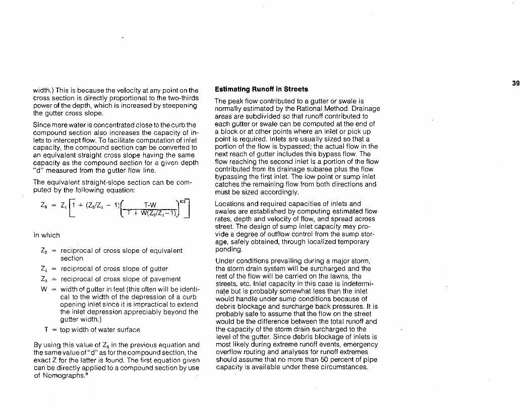
39 width.) This is because the velocity at any point on the cross section is directly proportional to the two-thirds
the gutter cross slope.
Since more water is concentrated close to the curb the compound section also increases the capacity of in- lets to intercept flow. To facilitate computation of inlet capacity, the compound section can be converted to an equivalent straight cross slope having the same capacity as the compound section for a given depth “d” measured from the gutter flow line.
The equivalent straight-slope section can be com- puted by the following equation:
Estimating Runoff in Streets
The peak flow contributed to a gutter or Swale is
areas are subdivided so that runoff contributed to each gutter or swale can be computed at the end of a block or at other points where an inlet or pick up point is required. Inlets are usually sized so that a portion of the flow is bypassed; the actual flow in the next reach of gutter includes this bypass flow. The flow reaching the second inlet is a portion Of the flow contributed from its drainage subarea plus the flow bypassing the first inlet. The low point or sump inlet catches the remaining flow from both directions and must be sized accordingly.
Locations and required capacities of inlets and swales are established by computing estimated flow rates, depth and velocity of flow, and spread across street. The design of sump inlet capacity may pro- vide a degree of outflow control from the sump stor- age, safely obtained, through localized temporary ponding.
Under conditions prevailing during a major storm, the storm drain system will be surcharged and the rest of the flow will be carried on the lawns, the streets, etc. Inlet capacity in this case is indetermi-
would handle under sump conditions because of debris blockage and surcharge back pressures. it is probably safe to assume that the flow on the street would be the difference between the total runoff and the capacity of the storm drain surcharged to the level of the gutter. Since debris blockage of inlets is most likely during extreme runoff events, emergency overflow routing and analyses for runoff extremes should assume that no more than 50 percent of pipe capacity is available under these circumstances.
power of the depth, which is increased by steepening normally estimated by the Rational Method. Drainage
+ = +
in which
= reciprocal of cross slope of equivalent
= reciprocal of cross slope of gutter = reciprocal of cross slope of pavement
section
width Of gutter in feet (this often will be identi- nate but is probably somewhat less than the inlet cal to the width of the depression of a curb opening inlet Since it is impractical to extend the inlet depression appreciably beyond the gutter width.)
T = top width of water surface
By using this value of in the previous equation and the samevalue of “d” as for the compound section, the exact Z for the latter is found. The first equation given can be directly applied to a compound section by use of Nomographs. 8

40 Criteria for Spread of Water Across Street
The allowable spread of water across the street from the curb is limited by the criterion of maintaining two clear ten-foot moving lanes of traffic for collector streets during minor storms. One clear lane should be maintained on subcollectors, and lanes and places may have a spread equal to one-half of their width. These criteria are fully justifiable in humid areas, but may be difficult to meet in arid areas where:
available slope is limited,
Flow Across Intersections
The most critical situation exists where a street on a grade intersects with another street, especially a col- lector or subcollector. Even when the flow on the grade is severely limited, great care must be taken to provide inlets which will intercept virtually all the flow from a minor storm. Full interception may be im- possible for a major storm.
A “T-intersection” requires special care because houses directly below a steep “T” stem are particu- larly subject to intersection overflow damage during major storms. Overflow .of “T” intersections can be somewhat impeded by:
runoff may contain considerable suspended solids, elevating the through-curb;
drainage essentially is by surface flow, and
the public accepts the resulting inconvenience.
When a steep cross slope is used (five percent is suggested as a limit), a ten-foot spread would pro- duce an excessive depth at the curb making it dif- ficult to intercept the flow except with a very long curb opening inlet.
Consequently with pavement cross-sloped from three to five percent, the depth of flow at the curb should not exceed six inches.
installing a higher-then-normal roadway crown on the through street; and
using a straight-faced through-curb of 7½ inch or greater height. In severe situations, a decorative wall (low) placed behind the through-curb and landscaped will provide practical control, often more economically and assuredly than inlet con- struction.
Flow across collector streets should not be allowed during frequent storms. Controlled flow across sub- collectors is acceptable and there are no design lim- itations placed on flow across lanes and places. Dur- ing major storms, permissible flow across intersec- tions will be a function of the street’s traffic-carrying importance and the availability of convenient alterna- tive access.

41 Ponding at Low Points in Grade
Some ponding of water at low points in the grade is inevitable, even during a minor storm, and in some cases may be desirable. However, because of the driving hazard and splashing of water on pedes- trians, ponding should be minimized. This is done best by intercepting most of the flow before it gets to the bottom of the grade. In picking up most of the flow prior to the sump location, a large percentage of sediment will also be removed from the flow. This prevents sediment deposition in the gutter as veloc- ity is checked on the decreasing grade. A curb- opening inlet at the low point in the grade is an effi- cient structure but must be of ample size because this is the point where debris is most likely to ac- cumulate. Effective performance during a major storm should be assured by considering:
damage from water overtopping curb and
methods of minimizing damage
relative sizing of inlet and pipe
overflow mechanisms
Maximum Velocity in Gutters
Water flowing down steep grades can be dangerous. For example, water flowing at ten feet per second can exert a force of 100 pounds against a flat, one- foot wide object placed across the flow. A 20-pound push at shoe level will sweep a grown man off his feet, so gutter flow can be very hazardous to a child. Aside from the safety hazard, such flows are difficult to intercept at inlets and can create difficulties, such as shooting across an intersecting street or overrid- ing curbs and causing severe localized erosion and sometimes damage to downhill properties.
A recommended criterion is that the velocity in the deepest part of the gutter be limited to ten feet per second. This velocity is readily computed by the Manning equation using the depth at a point six inches from the face of the curb as the hydraulic radius. 41 The mean velocity for the entire cross sec- tion is not a good measure. If the calculated velocity exceeds ten feet per second, the allowable dis- charge in the gutter must be reduced until velocity is within the limit. The designer is then faced with the problem of where and how to reduce the runoff enter- ing this gutter. Additional inlets could be installed upstream, but this is expensive. If possible, some way should be found to divert runoff to some path other than the steep street, preferably by a revised street layout. Future street resurfacing which will re- duce capacity should be considered in the calcula- tions.
sidewalk
NATURAL DRAINAGE 42
Natural drainage flow techniques serve very useful functions in the control and management of storm water runoff. The primary function is to provide an opportunity for natural infiltration of storm water to the ground water supply system. Secondly, it helps to control the velocity of runoff flows, which is a necessary factor in the control of erosion and sedimentation. Thirdly, and perhaps most important, natural drainage techniques can extend the time of concentration of storm water runoff, thereby con- tributing to the ultimate goal of maintaining the rate of runoff at or near the levels existing prior to de- velopment. As noted earlier, street swales can pro- vide up to about 40 acre-feet of runoff storage per square mile, thereby contributing significantly to runoff attenuation.
The achievement of the goals stated above is impor- tant. Urban and suburban areas have experienced a rise in the frequency of severe flooding and an in- crease in the amount of hazard and damage as-
tant factor in this phenomenon is the rate at which storm water runoff reaches the receiving streams from developments in the drainage basin. Natural storm water runoff systems can help to control that rate and release the accumulated runoff over a longer period, thus contributing to a reduction in the rate and volume at given points in the lower reaches of the receiving streams. This is especially important where older areas downstream of new developments either have inadequate storm drainage systems or a combined sanitary and storm sewer system. Specific
reduction in the amount of runoff contributed from each new development in the upper and middle reaches of a drainage basin will reduce the cumula- tive runoff impact of development thereby contribut- ing to reduction of hazard and/or reduction in the need for costly supplemental systems in the downstream areas. Natural drainage systems must be properly maintained to assure their continued per- formance at the designed capacity. It must be noted that open channel flows in residential storm water management systems are not completely “natural” systems, although they rely heavily on existing natural features and qualities of the development site. Virtually all development will increase the amount of storm water that becomes runoff during and after an event because of the impervious sur- faces used in development. Increases in runoff which change the dynamic equilibrium of natural areas used in the system mandate specific engineering solutions to conserve these natural systems and the predevelopment characteristics of the area. The cre-
or direction, changing of ground cover and the lining of existing channels with other materials, natural or man-produced are necessary in some parts of the system to achieve the desired objectives.
These alterations or improvements will have to be maintained if the total system is to function properly. The maintenance of swales and open channels in the interior areas of residential development is most crit- ical during construction. Debris from this source, in- eluding plastic wrapping materials and other non-
sociated with floods at or near past levels. An impor- ation of swales, alteration of small channel capacity

43 biodegradable substances, can diminish the capac- ity of the system or effect changes in the flow charac- teristics of the runoff which tend to cause erosion and sedimentation. After construction, internal maintenance problems within residential areas will not be significantly higher if property owners under- stand that their normal maintenance responsibilities are integrally related to regular public maintenance efforts. The primary problem areas for roadside swales or open channels are along major arterials bordering residential areas or areas where non- residential uses contribute large quantities of man- made debris.
An awareness of potential problems is the first step towards their prevention, but should not be an over- riding cause for rejection of a system which would produce benefits that exceed potential maintenance disadvantages.
The characteristics, function and maintenance of open channel elements should be evaluated prior to the final design of the total network which forms a residential storm water management system.
Overland Flow
In planning an open channel system, overland flow distances should be made as long as possible con- sistent with other constraints and requirements. Over- land flow should be over and through turf or other flow retardants such as ground cover or forest litter. This is one reason why natural woods should be pre- served whenever possible. Slopes of overland flow areas should be as flat as possible, but maintaining natural topography and ground cover should take precedence over regrading to achieve flat slopes.
Overland sheet flow is a significant factor affecting the peak rate of runoff reaching the first collecting channel. Gently sloping turf areas shorter than 100 feet will probably not detain runoff significantly dur- ing intense rainfalls. The runoff rate from meaningful overland flow areas will be substantially less than the rate at which rain is falling. Minor surface de- pressions due to irregularities in grading add further to the storage potential. In addition, the retarded passage of water provides additional time for infiltra- tion into the soil (if permeable), thus reducing the quantity of runoff. On paved surfaces, such as on parking areas, the storage in overland sheet flow is only about one-fifth as much as on turf, but is still a significant factor. On steeper slopes, whether pave- mentor turf, the velocity increases and storage de- creases, so that less time is required for runoff rates to become equal to the rate at which the rain is fall- ing. Most presently available mathematical models for computing runoff include the length and other characteristics of overland flow as essential inputs.
Hydraulics for Swales and Open Channels
When runoff reaches swales and open channels, principles similar to those for overland flow should be applied. If feasible, they should be wide and shal- low with a rough surface and on as flat a grade as topography will permit. In this way, storage will further retard runoff and reduce the peak flow. Flat slopes may present the problem of marshy low areas after a storm. A minimum slope should be estab- lished, based on soil permeability and the capacity of the swale or channel.

44 The Manning Equation is almost universally used in calculating open channel flow. Numerous aids to, facilitate computations are available including com- puter programs. A very useful publication for those not having access to a computer is Design Charts for Open Channel Flow. 5 This publication includes con- sideration of flow in open channels and swales on mild and steep slopes. Velocity of flow in open channels and swales is dependent on rate of flow, slope, surface roughness, and cross section and can be calculated using the Manning Equation. Suface roughness and consequent velocity will depend on the quality of maintenance. Well-mown grass will have a different surface roughness coefficient than tall grass.
Control of Erosion
In designing channels for erosion control, the veloc- ity must be estimated and compared to the allowable velocity for the material on which the water is flow- ing. Table 3 indicates the allowable velocities for grass channels. It should be noted that the quantity of water which can be carried in well-established, dense turf swales without erosion is surprisingly large, even for steep slopes. For urban residential drainageways, flow velocities for erosion potential evaluations should be based upon the ten-year fre- quency runoff event, which generally is a practical break-point between initial cost and excessive maintenance cost.
However, when the allowable velocity for a turf chan- nel is exceeded, there are a number of alternatives to consider as shown in Table 4. They include: lining channel with an impervious material; drop structures or other velocity and erosion control measures; gravel or rip-rap bottoms; and gabions (rock en- closed in wire baskets).
The probable performance of the open channels and swales should be evaluated for major storm runoff with respect to the depth and spread of water and the erosion potential. Antecedent flow conditions re- sulting from previous storms are an important con- sideration. Open channels and swales may suffer damage during major storms, even if properly de- signed. The potential for incurring these infrequent maintenance costs should be balanced against the initial cost of attempting to make them “flood proof” during the design process.
It is important that open channels be constructed in accordance with plans. When intermittent channels are sodded to the depth of the expected flow, they can immediately provide protection for minor storms. It is not practical to establish turf in a drainage channel by seeding and mulching unless jute mats, or similar protective materials, are placed over the seed bed.
Flow and Erosion in Natural Streams
Maintenance of streams in their natural condition is a desirable goal. A natural stream normally adjusts its cross section and slope so that they are in approxi- mate equilibrium and flowing bankful at the average annual peak flow rate. For greater flows, the banks are overtopped and flow also occurs on the flood plain. If the flood plain is then constricted due to de- velopment, more flow will be concentrated i n the channel, probably disturbing its equilibrium and re- sulting in more than normal erosion. Similarly, addi- tional erosion may result if the peak discharge is in- creased, even if the flood plain is not constricted. Limiting the minor storm discharge from a residential or other development to pre-developed flow rates is a means of controlling the peak discharge. The two concepts, of storage and the use of natural open channel flow, assist in this objective.

Permissible Velocity on:"
Slope Range Erosion-Resistant Easily Eroded Cover Percent Soils (fps) c Soils (fps) c
0-5 8 6 Bermudagrass 5-10 7 5
Over 10 6 4
Buffalograss 0-5 7 5 Kentucky bluegrass 5-1 6 4 Smooth brome Over 10 5 3
Grass mixture 0-5 5 4 5-10 4 3
Lespedeza Weeping loveglass Yellow bluestem Kudzu 0-5 3.5 2.5 Alfalfa Crabgrass
Common lespedezad Sundangrass d 0-5 3.5 2.5
Original table from Handbook of Channel Design for Soil and Water Conservation, Soil Conservation Service, U S Department of Agriculture Publication No SCS-TP-61 March 1947, revised June 1959
"Velocities in excess of 5 fps to be used only where good cover and proper maintenance can be assured "Defined as CL, CH, OH, GM, GP, GC and GW (Unified Soil Classification System Designation) 'Defined as ML, SM, SC, MH and OL (Unified Soil Clas- sification System Designation) "Annuals, used on mild slopes or as temporary protection until permanent cover is established
Source Slope Protection for Residential Developments, Na- tional Academy of Sciences, Washington, D C 1969

46 Table 4 ALTERNATE METHODS OF CONTROLLING EROSION IN OPEN CHANNELS
Type of Control Advantages Disadvantages
Permanent if carefully constructed and main- High cost. Speeds up runoff. 1. P. C. or asphaltic concrete or soil cement paving. tained.
2. Drop structures across channel at inter- vals so that slope of channel between built. Does not speed up runoff. have maintenance problems. drops restricts allowable ve loc i t y for t u r f . 41
3. Lining with crushed rock or gravel sized for requirements.' with landscape. Can allow both infiltration able locally.
Satisfactory if drops are well-designed and Unsightly, if natural material is not used. May
Satisfactory if well-designed. Can harmonize
into permeable soil and exfiltration of ground water.
Permanent i f carefully placed and main- tained.
Permanent if carefully placed. Can allow infil- tration on permeable soil.
Aesthetically pleasing-becomes invisible. No limit to range of flow.
Can be costly if rock or gravel are not avail-
4. Rip-rap. 42 Can be costly. Can be unattractive.
5. Rockenclosed in galvanized wire baskets (gabions). This generally requires wide shallow channels so that drops will not be over-ridden and channels destroyed dur- ing unusual extreme flow events.
Can be costly.

UNDERGROUND PIPE SYSTEMS
Layout of the Storm Drain System
The layout of the storm drain system for residential areas should make maximum use of existing open channels and natural streams, before resorting to enclosure of runoff in underground pipes. Former practice tended toward enclosing small streams in conduits which was not only costly, but also concen- trated the flow downstream and increased the peak rates of discharge. The preferred approach is to leave natural streams undisturbed and to limit peak runoff conditions. Erosion of the stream channel usu- ally is not accelerated when this is accomplished. As recommended in this report, runoff will be collected
tions and carried as far as practical before entering
system consists of a series of inlets, pipes, and
detailed design of the system. Decisions made in the planning stages of the residential development, some of which are listed below, will have a great in-
pipe system.
Planning of both minor and major components with curbs. 33 appropriate design rainfall recurrence intervals. Limitation of peak runoff rates after development.
Type and amount of storage.
Use and incorporation of natural drainage such as overland flow, street swales, open channels and natural streams. Assurance that all contributory upstream areas will be similarly regulated or initially assessed and developed, so projected conditions may be relied upon.
47 Pipe Location and Alignment
The pipe system is usually in the street right-of-way, but portions may be in easements along lot lines when that route provides the best outlet path to a natural stream. One common location within the right-of-way is behind the curb. This method con- nects inlet boxes with the least amount of pipe and junctions.
There is no reasonable objection to the pipe being laid on horizontal and vertical curves conforming to the curvature of the street. The horizontal and vertical alignment of storm drain pipes must be coordinated with the location of all other uilities. In cases where
and possibly water lines is allowed, it is much easier
struction. Since storm drains are generally con-
trench backfill density control, the opportunity for joint trenching with other utilities rarely exists. As most localities now require electrical power and
are possible conflicts with utility poles behind
in swales or open channels and curb and gutter sec- joint trenching of electrical, telephone, CATV, gas
an underground pipe system. The underground pipe to coordinate the locations of utility lines during con-
manholes. Output from computer sirnulation models of runoff or empirical techniques may be used in the structed early in a residential project, require gravity
profiles, are located at shallow depths, and require
fluence on the final form and cost of the underground telephone lines to be underground, there no longer

Culverts Materials
With the emphasis on keeping surface runoff in street swales and open channels, culverts may be required for street crossings. Driveways crossing properly de- signed street swales should not automatically re- quire culverts, as vehicles should be able to cross the swale. When required, culverts preferably should have flared end sections for good appearance and hydraulic characteristics. 9 Precast or pre-fabricated flared end sections for pipes are available.
Any culvert will cause an increase in water level in the upstream channel. This backwater can flood
with which this is allowed to happen should depend on the amount of damage, including delays to traffic, caused by the backwater.
a road fill can provide a dam for temporary impound- ing of storm water. l8, 35 Legal and physical require- ments for such temporary ponding are constraints to be considered.
Culverts may also require energy dissipators at the outlet if the stream bed is erodible. These can range from simple placement of rip-rap to elaborate con- crete stilling basins. Similar structures may also be required on storm drain outlets. 6, 45
48
Storm drain pipes are most commonly plain or rein- forced precast concrete; however, other materials may be used. 16 There has also been good experi- ence using carefully controlled installations of un- reinforced cast-in-place concrete pipe, which may also provide initial construction cost savings. Corru- gated metal pipe can be used for short runs, but its high resistance factor often requires a larger pipe size for equivalent flow capacity which weighs against its use for long lines, unless grades are very steep or unless the invert and sides are lined with asphalt to give a smooth interior. Where culvert hy-
corrugated metal pipes may be interchanged size for size.
Curb opening inlets are usually reinforced concrete,
Concrete block can also be used for walls if the inlet opening is short. On longer openings, the structural problem of carrying the top slab across the opening with no intermediate supports and very limited thick- ness of slab allowable, may require cantilevering the slab off the rear wall of the reinforced concrete inlet box.
Manholes can be brickmasonry or reinforced con- crete and are frequently built as precast concrete units. Fiberglass units are seeing limited use.
property and overflow into the streets. The frequency draulics are governed by inlet control, concrete and
Where storage is required to controI peak discharge, often with precast units for top slabs and other parts.

49 Hydraulics
The usual hydraulic practice is to select the pipe size for the accumulated runoff rate at each inlet or manhole assuming that the pipe is just barely flow- ing full. For the water to accelerate to the uniform flow velocity computed from the Manning Equation, water must back up into the inlet to a depth above the pipe equal to the outflow velocity head plus the inlet lateral entrance loss. Standard practice also re- quires that the hydraulic gradient, or pressure head line, be computed for the full length of the pipe sys- tem, usually starting at the downstream end. The pressure (head) losses at junctions must also be computed. 37 Guide vanes and other geometric im- provements within the junction or manhole can be used to minimize pressure losses. The pressure los- ses become particularly significant for velocities in excess of eight feet per second. The pressure line should be kept close to the crown of the pipe for the design discharge of the minor rainfall. Surcharging the pipe with the pressure line above the crown of the pipe but still remaining about 0.5 feet below ground level is acceptable.
During a major rainfall, the underground system will be under pressure with the pressure line probably at the surface of the water in the gutter. Since the pipe slope is usually about the same as the street slope, the pipe will be carrying only the discharge for that slope, the remainder of the storm water being on the surface of the street. When testing a tentative design for performance under major storm runoff conditions, it may be necessary to increase the size of one or more reaches of pipe to avoid incurring excessive damage costs resulting from overflowing the street. Other alternatives for disposing of the excess flow may be more economical.
The minimum pipe size required should be based on hydraulic considerations rather than arbitrary stan- dards; it should be noted that if a less than 15-inch pipe is satisfactory, then the storm sewer is probably unnecessary, since a curbed 26-foot wide roadway will handle more than three times the flow of a 15- inch pipe on the same grade. Consideration should be given to hydraulic capacity of a pipe given its size, slope and roughness characteristics, tendency to become clogged, self-scouring velocities and ability to clean the pipe and remove obstructions. The use of street swales to collect water, and criteria which allow more flow in gutters prior to initial pick- up, will mean that the initial minimum pipe size will generally be larger than under the old philosophy of “get it into pipes as quickly as possible.”
The minimum allowable velocity to keep small parti- cles of sediment moving in a pipe is about two feet per second. It is advisable to have a minimum pipe slope of about 0.1 percent in the approach to a junc- tion box. While the thrust of the storm water man- agement program includes keeping sediment out of the system as much as possible, some sediment load may be unavoidable. With a heavy sediment load, coarser particles may settle out where there is a reduction in transport capacity because of de- creasing grade. 21

The use of an inlet box as a sediment trap is ill-ad- vised. Experiments have shown that the turbulence created by the falling jet moves sediment beyond the box. In addition, catch basins are costly to clean out, and the pipe system usually has the capacity to carry away the sediment anyway. If trapping of sediment becomes necessary, it should be done by designing a sediment trap located at a point where the pipe capacity to transport sediment is reducing. The trap should be accessible for cleaning with mechanical equipment. Storm water loaded with abrasive sedi- ment particles can cause wear on a concrete pipe at high velocities, so the entrance of such sediments should be minimized. The duration of storm water flow is relatively short and infrequent so abrasion by particles that do get into the pipe may not be seri- ous. There is little that can be done to slow down
drop structure to dissipate excess energy.
Difficulty with high velocity flow is more likely to occur when the energy gradient (the position of pressure head plus the velocity head) is allowed to rise well above the ground surface at a manhole where the pipe slope decreases abruptly. A hydrau- lic jump can occur which would check the velocity and result in conversion of velocity head to pressure head sufficient to blow off the manhole cover or the whole top of the manhole. This is a particular prob- lem where pipe alignments cause flow through inlet boxes, which are often shallow, as the intended inlets may instead function as outlets.
Manholes
The principal purpose of manholes is to provide ac- cess for cleaning and inspection. They usually should not be more than 500 feet apart on small pipes; spacing may be greater for larger pipes and unlimited for 66-inches and larger. Maintenance and safety requirements will dictate spacing on the big pipes. Inlet boxes should also have manhole open- ings to provide access. If storm drain pipes run through inlet boxes, they can be used for inspection and maintenance and can be counted when deter- mining minimum spacing. This practice is only rec- ommended where there is no likelihood of soil movements or external live loads on the inlets. Where pipes are routed through inlet boxes both pipes and boxes usually must be at least one foot below conventional depths to offset hydraulically ad-
es, to assure functioning of the inlets.
50
water on a steep grade, other than building a vertical verse head recoveries, turbulence and entrance loss-

STORM WATER INLETS 51
Storm water inlets are located at the transition be- tween open surface flow and a closed conduit sys- tem. They are either constructed as part of the street’s curb and gutter system, located in street swales or used to drain open areas. The inlets should remove runoff from surfaces when the flows exceed the criteria for velocity, spread of water across streets, or flow across intersections. Inlets in street swales also remove flow when it exceeds swale capacity. Drainage of open areas is often picked up by an inlet in a depressed area.
In utilizing natural systems effectively, the employ- ment of inlets should be delayed as long as possible because as soon as the runoff enters the pipe sys- tem, it is carried rapidly downstream.
Grate Inlets
Grate inlets consist of metal bars or a grid encased in a frame. When grate inlets are placed in the street, the bars are usually aligned with gutter flow for maximum hydraulic efficiency. This allows the inter- cepted water to fall between the bars. The bars of the grate may be placed at right angles to the curb for the safety of cyclists. When this is done, water hitting the bars may be projected upward, causing some of the flow to be deflected away from the inlet. The effi- ciency of both applications is improved by depress- ing the grate below the plane of the gutter within the transition area. This creates a sump condition and the small amount of ponding helps reduce approach velocity abating the tendency of the water to be de- flected beyond the inlet.
Grate inlets are often placed in street swales and other overland flow areas, when it is necessary to intercept the flow due to velocity or the lack of a satisfactory route for continued flow. Grate inlets are also used to drain parking lots. The design of these inlets must account for any expected reduction in inlet interception capacity due to clogging by grass cuttings, and water borne debris.
Periodic maintenance to assure the capacity of the inlet is necessary. Grate inlets in unpaved areas should be placed according to the most efficient de- sign, as it is not likely that bicycle traffic will be a factor in this type of installation. Grate inlets on urban streets are not recommended.
Curb Opening Inlets
The capacity of an inlet to intercept water flowing down the street depends to a large degree on the distribution and velocity of water in the gutter cross- section. On a continuous grade, an inlet will inter- cept only that flow within its hydraulic reach. In the case of the curb opening inlet, the width, length and depth of the depressed section of the gutter in front of the opening is very important. Steepening of the cross slope of the gutter enables gravity to begin turning the flow into the opening, but because of the inertia of the flow considerable opening length is necessary.

52 The vertical height of the opening should be not greater than six inches in order to eliminate the pos- sibility of a child being washed into the inlet basin. This places a restriction on hydraulic capacity for major storm conditions when most of the street may be flooded. The outlet pipe would probably be flow- ing full by that time and would limit the inflow any-
entire length on continuous grades.
A sediment trap formed by lowering the floor of the inlet box below the elevation of the outlet pipe is un- necessary and undersirable since there is too much turbulence for effective trapping, and cleaning is costly.
Capacity of Curb Opening Inlets The most authoritative data on capacity of curb open- ing inlets is contained in a circular published by the Federal Highway Administration (FHWA). 8 That report includes charts for estimating the interception ratio
for inlets five, ten and fifteen feet long, and curb widths of one, two and three feet when used on street sections with cross slopes ranging from 0.015 to 0.06 ft./ft. and roadway grades up to four percent. The charts, as published, are based on full scale tests by Colorado State University. Extension of the charts to steeper grades has been developed and is awaiting pubIication.
Curb Opening Inlets at Sump Locations
Curb opening inlets at a low point in the grade (sump) operate efficiently, since the water is trapped at the opening. Charts are available for estimating the capacity of inlets five, ten and fifteen feet long in terms of the depth of ponding over the inlet lip. 8 It also has a procedure for determining when a given
will occur in the approach gutters, thus increasing the width of ponding. For major storms, the restric- tion caused by the outflow pipe may govern.
Curb Opening Inlets-Deflector Type
The state-of-the-art literature contains references to the use of deflector vanes on the surface of the de- pressed gutter in front of an inlet to force more water into the curb opening. The only experimental data available on deflector vanes were based on a steep crown slope S, = 0.055 with a narrow range of water depth and with water spread only twice the width of the depression. These results are not applicable to flatter cross slopes, and are applicable least of all to large ratios of water spread to curb width. The Col- orado experiments on which the charts in FHWA’s Drainage of Highway Pavements were based dem- onstrated conclusively that the interception ratio is a function of water spread to curb width. 8
The use of deflector vanes is not recommended, since they complicate construction and in the past have been rendered inoperative when buried by street resurfacing.
way‘ The opening preferably should be cIear for the inlet will restrict flow to the point where backwater

53 OTHER DESIGN CONSIDERATIONS Soil Erosion
Control of erosion during residential construction re- quires an examination of the entire site to pinpoint potential problem areas, such as steep slopes, highly erodible soils, soil areas that will be un- protected for long periods or during peak rainy sea- sons and natural drainageways. Steps should be taken to assure erosion control in these critical areas. After a heavy storm the effectiveness of ero- sion control measures should be evaluated. Periodic maintenance and cleaning of the facilities is also important.
Control of erosion after construction consists primar- ily of minimizing bottom and side scouring of natural drainageways. This can be accomplished by proper initial design which limits velocities and specifies correct drainageway linings and structures, and by proper routine maintenance and repair of the system.
Some of the basic concepts for controlling erosion during and after construction are: 2, 7, 30, 54
Earth slopes: Erosion of cut or fill slopes is usually caused by water concentrations at the top of the slope flowing down an unprotected bank. Runoff should be diverted to safe outlets. Slopes should be protected from erosion by quick establishment of vegetative cover, benches, terraces ,slope pro- tection structures, mulches, or a combination of these practices as appropriate.
Waterways or Channels: Waterways should be de- signed to avoid serious erosion problems. Wide channels with flat side slopes lined with grass or other vegetation will usually be free from erosion. Where channel gradients are steep, linings or grade control structures may be required. Space limitations may make it necessary to use concrete or stone linings. Every effort should be made to preserve natural channels.
Structures for Erosion Control: Erosion may be con- trolled by the use of grade control structures, energy dissipators, special culverts, and various types of pipe structures. Structures are expensive and should be used only after it has been deter- mined that recommended vegetation, rock revet- mentor other measures will not provide adequate erosion control.
Existing Vegetation: Good stands of existing vege- tation adequate to control erosion should be pre- served wherever possible.
Soil Treatment, Seeding and Mulching: The ability of the soil to sustain vegetation intended for ero- sion control must be ascertained. The admixture of a fine textured topsoil may be warranted to assure success of more attractive, lower maintenance vegetation. Liming and fertilization should be done according to recommendations based upon soil test information. After the soil has been pre- pared, the correct seed mixture, sod, ground cover and mulch should be applied.
Outfall Design: The outfall pipe should be de- signed and located so as to minimize erosion; especially if the outfall is to an overland flow area with a steep slope or is elevated above the base flow of the receiving streams. An energy dissipator may be necessary.

Siltation and Sediment Control
Proper control of soil erosion during and after con- struction is the most important element of siltation and sediment control. However, it is physically and economically impractical to entirely eliminate soil erosion. Secondly, erosion is a natural function and is required in certain portions of the drainage system in order to provide future stream capacity. Therefore, provisions should be made to trap eroded material at specified points. Some measures that can be im- plemented are: 11, 30, 54
Temporary ponds which store runoff and allow suspended solids to settle out can be used during construction and may be retained as part of the permanent storage system after construction.
Protection of inlets to the underground pipe sys- tem can be accomplished during construction by placing hay bales around the structure. Egress points from construction sites should be controlled, so that sediment is not carried off-site by construction traffic.
Storm Water Runoff Pollution
As storm water runoff flows over surfaces, it picks up pollutants and carries them downstream. The mag- nitude of the pollution load has been the subject of recent investigations by the Environmental Protection Agency (EPA) and others. 2, 38 It is generally con- ceded that the magnitude is sufficient to warrant serious examination of alternate methods of control- ling and treating storm water runoff pollution.
Documentation of pollution loads in streams before and after construction is a necessary first step prior to embarking on extensive runoff treatment pro- grams. Measurements might include suspended sol- ids, Biochemical Oxygen Demand (BOD), dissolved oxygen and the concentrations of toxic materials, bacteria and nutrients. Under ideal conditions the measurement of pollution should be coordinated with simultaneous collection of data on rainfall and runoff. Pollution loads are the result of:
soil erosion and dissolving of minerals in the natural ground cover;
overland flow which picks up fertilizer, animal droppings, and organic material, and
flow on parking lots, roofs and streets which car- ries petroleum products, trash, dust fall and debris from cars and trucks into the drainage system.
54
Three basic methods of treatment can be used:
The first controls pollution loads at their source. For example, proper erosion control and sediment control will reduce the suspended solids levels. Also, periodic street cleaning will reduce pollution loads.

55 Storm water runoff can be treated at the source. Temporary storage of runoff to allow suspended solids to settle out is one example. Diversion of runoff to land treatment areas for spraying or con- trolled overland flow is another. The fact that most runoff pollution results from the “first flush” of runoff should be considered when planning source treatment facilities. Treatment of storm water runoff at a centralized plant downstream is the third alternative. This is probably the most costly method because of the vast volume of water requiring treatment. Consid-
storm water to be released to treatment plants at a gradual rate after the runoff peak has passed.
Treatment of runoff to reduce pollution loads is probably unnecessary for most low-density resi- dential development, but the availability of perti- nent information is limited. It seems obvious that the cost of such treatment will be high, so it fol- lows that treatment should not be considered un- less there is documentation of the need and a demonstration that the benefits from treatment will be consistent with its costs.
Maintenance
Adequate provision for short- and long-term mainte- nance of the residential storm water system is an im- portant design consideration. Maintenance and re- placement needs and costs should be part of the economic analyses.
Maintenance requirements for the type of system suggested in this document may be different from those for a fully enclosed pipe system. Mowing, trash and sediment removal, replacement of sod and re- pair of eroded areas will become parts of the
tions, repair and cleaning will be required.
When planning an on-site storage system, determina- tion must be made about long-term ownership and/or maintenance and operation of the facility. The choices will generally be between public and private organizations and the final decision will be depen- dent on local conditions.
eration may be given to storage facilities enabling maintenance program. Conversely, less pipe inspec-
In a subsequent discussion of basic legal aspects of urban drainage and flood control, potential liabilities associated with land use and development are out- lined. The direction of liability may be shifting, by placing increasing culpability on parties involved in the approval of land uses in a hazardous area or in the creation of hazards. The availability from FIA and others of hazard information and delineated potential hazards makes it easier to assess liability for im- proper location or land use.
As a result of FIA actions and Federal regulations re- lating to flood hazards, local governments have been stimulated to provide new regulations for their juris- dictions. These regulations cover areas delineated by FIA and may cover tributary and headwater areas not currently mapped. The new regulations do not prohibit all development in potential flood hazard areas but rather require that development be consis- tent with wise floodplain management to qualify for insurance or loans from federally regulated or in- sured institutions.
Within flood hazard areas, there are often locations where occupancy is fully justifiable under certain conditions. The Minimum Property Standards (MPS) of the Department of Housing and Urban Develop- ment recognize this and permit floodplain occu- pancy provided the finished first floor of a dwelling is no lower than the 100-year frequency flood elevation and the building site grades adjacent to the dwelling area are no lower than the 50-year frequency flood level.
56 Encroachment into Potential Flood Plain Areas No consideration of residential storm drainage is' complete without recognition of potential flood hazard exposure. These potential hazards are obvious along major rivers and streams but can also occur along tributaries and drainageways and in headwater areas as will be discussed later.
Management of major drainage basins and rivers is usually control led by other than local governments; however, local government should be concerned with controls for development in all other areas sub- ject to flooding.
The Federal Insurance Administration (FIA) is cur- rently involved in a two-staged effort to delineate and map some floodplains and their potential flood ele- vations for many communities as part of an effort to provide insurance for structures located in areas of potential hazard. The first stage provides a gross de- lineation of the floodplain, to permit subsidized in- surance for properties already located within a hazard zone and a basis for planning future land uses in such areas. The second phase provides more accurate and detailed mapping of the flood- plain to guide future land use practices and deter- mine insurance rates for structures permitted to lo- cate in a designated hazard zone. It will take years to complete this mapping effort, and it is uncertain whether it will be possible to identify and map all po- tential flood hazard areas. Thus it is necessary for all involved in the process of land development to rec- ognize and consider any potential flood hazards as- sociated with the land being developed.
57 In practice, the use of the 50-year frequency flood elevation as a limit to acceptable encroachment upon a flood plain may justifiably be varied. Where the difference in elevation between the 50-year and 100-year frequency flood levels is less than eight inches, it often will be fully justifiable to occupy sites having elevations below the 50-year frequency flood elevation, sometimes as low as the 20-year fre- quency flood elevation, if dwellings will have their floors at or above the 100-year flood elevation and the dwellings will have no basements. This justifica- tion reflects the typical low-flow velocity of floodwat- ers in such locations and the minimal effect of build- ings upon flooding depths upstream from such loca- tions. Where the difference in elevation between the 50-year and 100-year frequency flood levels is more than eighteen inches, residential encroachment upon the flood plain to the 50-year frequency flood eleva- tion generally is unwise since potential flooding depths and fast-flow velocities could cause severe damage to properties. Where properties may poten- tially be flooded for more than a few hours, more stringent encroachment limits than the 50-year fre- quency flood elevation may be appropriate because the social displacements and flooding damages will usually be greater than from short-term flooding of similar depth. Of course, technical justification of a variation will not necessarily be acceptable to regu- latory authorities.
The economic benefits that may be derived from oc- cupancy of portions of a designated special flood hazard area, or other areas subject to flooding, may be appreciably greater than probable future flooding losses. There is a statutory provision for Federal ac- ceptance of alternative land use and control mea- sures applicable to such locations, but the burden of developing alternative measures and demonstrating their assured fulfillment of Federal loss mitigation ob- jectives is upon the local community. The community must demonstrate conclusively that the economic and social benefits derived from occupancy will be greater than, and of overriding importance relative to, the potential flooding losses. For locally-suggested alternative measures to be given credence, propo- nents of the alternative measures should clearly explore whether immediate costs and adverse ef- fects upon property values, tax revenues and public facilities (including utilities), attributable to adoption of generally promulgated land use and control mea- sures, are greater than the probable future flooding losses discounted to present value. Locally- suggested alternative measures should also de- monstrate how their implementation would mitigate future flooding losses, and to what degree. Regard- less of whether flooding is caused by inadequate drainage or by streamflow, the derivation and sup- port of locally-suggested alternatives optimally re- quires interaction and close cooperation among all local interests.

Selection of appropriate types of dwelling units for construction in areas exposed to flooding may signif- icantly reduce potential flooding losses, by compari- son with potential losses using other dwelling types. Where the occupancy will be in a community that is generally exposed to flooding, or in a substantially developed area in which it is not feasible or reason- able to forego building upon vacant sites, selection of the merchantable building type having the lowest flooding loss expectancy is appropriate. In such situations, the probable market response to a change
decision making. Based upon the Federal Insurance Administrations' Depth-Damage curves, 10 the relative flooding loss characteristics of common types of res- idential buildings are as follows:
Ratio of Damage* Building Type
Additional loss mitigation can be effected by reducing land occupancy densities, thereby reducing the total value of exposed property per acre, and by floodproof- ing, to reduce the losses expected from any given level of potential flooding. Floodproofing 17, 19, 44 involves a series of construction modifications either to exclude water from entering buildings or to reduce the potential for water damage if water does enter buildings. In some situations, floodproofing can reduce potential flood losses by as much as 60 percent by minor initial increases in construction costs.
croachment into flood plain areas discussed above tend to presume a continuation of past practices in runoff management in upstream tributary areas, A major objective of this publication is to encourage new approaches to storm water runoff management which would attenuate peak runoff thus reducing frequent flood hazard threats in the middle and lower reaches of a drainage basin. Thus, application of the objectives, principles, and design considerations set forth in this publication may in themselves provide further justifi- cation for cautious variations of limitations on land use in flood hazard areas.
58
in building type should be carefully assessed during The potential for flood hazards and the issues of en-
Two-story dwelling without basement Split level dwelling 1.15
One-story dwelling without basement 1.5 One-story dwelling with basement 1.65 Mobile home 2.3
1.0
Two-story dwelling with basement 1.2
*Base level is two-story dwelling without basement
As shown, substitution of a building type with a les- ser loss potential could reduce potential average annual flooding losses to levels comparable to loss expectancies outside of other designated special flood hazard areas. Where such an alternative rela- tionship can be demonstrated, there would seem to be a persuasive argument for acceptance.

59 Potential Flood Hazards in Tributary and Headwater Areas
The prior discussion has been concerned with flood- ing associated with overflow of channels, streams and rivers into adjacent, generally identifiable, flood haz- ard areas. There is considerable potential for water damage associated with unwise siting and drainage practices which are often overlooked and are often a source of residential flooding in tributary and headwa- ter areas. These hazards generally are foreseeable, are usually the result of poor application of good de- sign practices, and can be avoided without significant increase in development or construction costs.
Streets, highways and railroad crossing drainageways or streams are commonly elevated, on embankments, with culverts or small bridges passing beneath them to accommodate runoff flows. When the runoff flow is too great to pass through the culvert or bridge, or when the culvert or bridge is blocked by debris, the embank- ment will act as a dam causing runoff to accumulate upstream and possibly overflow the embankment. The depths of potential flows over roadway embankments are variable and should be computed, but most com- monly are from one to two feet. The potential for resi- dential flooding upstream from drainageway-crossing embankments can be eliminated if dwelling floors and openings into dwellings are higher than potential runoff overflow elevations at embankments. Failure to recognize such conditions is a widespread source of residential flooding. A proper application of the blue green concept discussed elsewhere should eliminate this hazard.
One common but easily overlooked source of residen- tial flooding occurs where runoff from small areas will naturally follow a lot line swale between dwellings. Even though a drainage area may be very small, the
quantity of foreseeable funoff will be frequency- related. The worst foreseeable flows should be antici- pated during design. Appropriate designs for such locations will consider both the size of the swales and the elevations at which buildings are sited. There is always a potential for water-related damage, from storm water runoff or ground water, to structures im- properly sited or improperly graded. Thus, detention ponding on individual sites, as suggested elsewhere in this publication, may be impractical or unwise be- cause of such local problems as impermeable soils, expansive soils or seasonally high ground water. Under such conditions, positive drainage of individual building sites may be essential.
Some relationships between basement construction and flood hazard exposure should be emphasized. Typical basement construction is incompatible with on-site detention ponding where site soils are more than slightly permeable and where detention ponding mightcontributetothe rise of ground water to building footing elevations. The most commonly observed cause of residential basement flooding is entry or pen- etration of storm water runoff due to the failure to drain runoff quickly and positively away from buildings. Where soils are essentially impermeable, protective slopes around a dwelling can be used to assure quick and positive drainage of runoff away from the dwel- lings either to off-site locations or to ponding storage areas on-site with controlled outfall.
Again, it should be emphasized that the flood or water damage hazards described here would be the result of improper site-specific application of recommended design approaches suggested earlier in this publica- tion. Proper application of on-site detention, and proper use of swales and other engineering tech- niques should avoid creation of residential flood hazards.

LEGAL IMPLICATIONS Homebuilders and developers are familiar with zon- ing, subdivision regulations and building codes. Storm water law is another control which the public sector has placed on the use and development of land or which has arisen through liability imposed by courts when the acts of one land owner have ad- versely affected the property of another. Storm water law, like storm water engineering, can be divided into two areas-floods and drainage—even though they obviously belong to the same system of surface water runoff.
Regulating the Flood Plain The flood plain is usually defined as that area bor- dering a watercourse which would be inundated by a flood of a certain magnitude. The magnitude used in establishing the federal flood hazard areas is the “one-hundred-year flood”, that is, a flood which has a statistical one percent chance of occurring or being exceeded in any one year. Often this flood plain is further subdivided into a “floodway” and a peripheral area.
Billions of dollars have been spent on flood protec- tion works. In spite of this, nationwide flood losses have continued to escalate. The response to this di- lemma has been a change in philosophy in dealing with flooding. Instead of attempting to keep rivers away from people by damming and channelizing them, the trend is towards keeping people away from rivers by preventing further unwise encroachment onto the flood plains. This is not to say that no de- velopment should occur at all, but rather that de- velopment must be consistent with good flood plain management. The greatest impetus has come from the federal government through its National Flood In- surance Program, the Flood Disaster Protection Act of 1973 (PL 93-234, amending 24 U.S.C. Ch. 50).
60 Briefly, it works in the following manner. First, spe- cial flood hazard areas are identified and designated on maps by the federal government. If the community has become a ”participating community” by adopt- ing adequate land use measures and other controls for its flood plains, those buildings which already exist in the flood hazard areas are eligible for heavily-subsidized flood insurance. Flood insurance for new construction, however, will not be sub- sidized; instead, premiums will reflect the actual flooding risks to the property. The crux of the pro- gram is that flood insurance is required before the vast majority of lending institutions in the United States can make, increase, extend or renew any loan secured by improved real estate located or to be lo- cated in one Of these special flood hazard areas. For the developer, this means he must investigate whether or not the property he proposes to develop is or is likely to be in a federally-designated special flood hazard area. If it is, and the community has failed to become a “participating community” by adopting acceptable land use controls, residential financing will probably be unavailable. If the land is within a “participating community,” the developer must investigate what controls the community has placed on the land and what the flood insurance costs would be. A federal rate map identifies appli- cable insurance rates. Occupancy and insurance costs can be mitigated by taking certain precautions (such as raising the elevation of the building), but may still make construction in that location less feas- ible. Therefore not only how the building is con- structed, but whether the building should b e built at that site at all, is an initial consideration affected by the National Flood Insurance Program. Another site, outside of the hazard area, may be financially more advantageous for development.
61 Additionally, even if the federal government has not designated an area, both state and local laws should be consulted. Some states and communities have adopted flood plain regulations and maps on their own initiative, or areas in addition to the federally- designated areas might be locally controlled, such as on smaller tributaries of the main stem. Local land use controls may be in the form of building codes, subdivision regulations, or specific flood plain regu- lations. Since the floodway is supposed to be adequate for the safe passage of the floodwaters through the community, building restrictions within it are severe. In the peripheral area, sometimes called the low-hazard zone or flood storage area, develop- ment is usually permitted within certain less restric- tive design parameters and precautions. Since the federal requirements are minimum, local flood plain controls can be more restrictive. It behooves a de- veloper to find out what they are. Some regulations declare that a building which is not in compliance with the flood plain regulations is a public nuisance which can be enjoined or even abated. In addition, where such development is the proximate cause of injury to the person or property of another, and the non-compliance could constitute negligence, the owner or developer might be liable for damages in a tort action.
Drainage Law
While flood plain reguIation is of fairly recent vin- tage, drainage law dates back to ancient times. Here we are looking at the respective rights and duties of the “upper” landowner versus the rights and duties of an adjoining “lower” landowner. The “upper” land lies at a higher elevation, and water drains down onto the “lower” land. This relationship is based on the lands in their natural, unaltered state.
There are basically two doctrines which have been adopted by various state courts: the “common enemy rule” and the “civil law rule”. Under the “common enemy rule” the lower landowner may take any mea- sures necessary to keep water off his land, even to the point of turning the water back onto the upper land. The upper owner can similarly protect his property from the “enemy” by diverting water around his property causing greater quantities at higher ve- locities to flow onto his neighbor’s land. In its pure form it would be a might-makes-right situation.

Therefore, courts have modified the rule to require that such acts be reasonable vis-a-vis each other. The “civil law rule” states that the upper land owner has an easement over the lower land for the natural drainage off of his land. The key word is “natural”, meaning the same quantity and velocity as drained from the upper land in its undeveloped state. It was felt that, in its pure form, the law would substantially restrict development of the upper land, so again courts have modified it to accommodate reasonable use of the upper property. Finally, both of these doc- trines, which are based on the property-law concepts of dominant versus servient lands, have been re- jected by some courts. These courts focus on “rea- sonable use” alone, based on tort-oriented law. While these modifications tend towards the same re- sults, the practical questions of predictability and proof requirements remain substantially different.
The developer will want to protect himself from pos- sible exposure to a potential liability suit for dam- ages, or from a time-consuming and costly injunction action. Under any of the doctrines mentioned above, his best protection is to develop in such a manner as to keep the runoff as close as possible to runoff con- ditions in the natural state—in quantity, velocity, and location. If he has obtained the hydrologic, soils, and other data recommended for good engineering de- sign, and has developed his project accordingly, the same facts will protect him from liability because he can prove that he has not materially changed the na- tural drainage conditions and has acted in a reason- able, non-negligent manner.
Some communities have established special as- sessment districts or storm drainage fees for the purpose of constructing drainage improvements. The developer should also investigate how these might affect the property. The basis for the fee may be the difference between the amount of runoff which was generated from that property in its developed condi- tion. Here again if the same amount of runoff has been maintained, by on-site ponding or other tech- niques, the fee may be negligible. If, on the other hand, the natural permeability has been reduced by extensive paving, he may be committing the property to be subjected to high drainage fees. Or the fee may reflect the cost of flood control works which are necessary to remove the property from a flood hazard zone. This may affect not only how he con- structs, but whether he constructs there at all.
Conclusion From a legal point of view, as from an engineering point of view, the developer must accept the fact that every piece of property involves storm water runoff in either a major or minor way and as both a contributor and recipient. It is imperative, before purchase or development, to get the physical facts and to inves- tigate the local, state and federal laws which could affect the property. The storm water aspects of the property may be one of the control ling factors on how to develop or even whether to develop that site at all. However, after having done his homework, and de- veloped the property in a responsible and reason- able manner, the developer can rest assured that he has good protection from liability.
62

References 14. Hydrocomp International. Inc.. Studies in the 27. McPherson. M. B. and W. J. Schneider. "Prob-
lems in Modeling Urban Watersheds." Water Resources Research. Vol. 10. No. 3. American Geophysical Union. June, 1974. 1965.
41. Searcy. J. K , Design of Roadside Drainage Channels. Hydraulic Design Series No 4 Wash- ington. D.C.: Bureau of Public Roads. May.
1. Anderson, A. G.. Amreek S. Paintal &John T. Davenport, Tentative Design Procedures lor Rip-Rap Lined Channels. Washington. D.C.: Highway Research Board, National Academy of Sciences, 1970. National Cooperative Highway Research Program Report No. 108.
Application of Digital Simulation to Urban Hy- drology. Palo Alto. California: Hydrocomp. 1971
15. Izzard. Carl F.. "Hydraulics of Runoff From De-
63 veloped Surfaces." Highway Research Board Proceedings. 26th Annual Meeting. Washington. D.C., 1946. The Academy. 1969. Engineering Circular No. 11.)
16. Joint Committee of the Water Pollution Control Federation and the American Society of Civil Engineers, Design and Construction of Sanitary and Storm Sewers. WPCF Manual of Practice No. 9. Also available as ASCE Manual of Practice No. 37. New York, NY.. 1969.
28. National Academy of Sciences. Slope Protection 42. Searcy. J. K.. Use of Rip-Rap lor Bank Protec- lor Residential Developments. Washington. D.C.: lion. Federal Highway Administration (Hydraulic
2. Becker, Burton C. and T. H. Mills, Guidelines lor Erosion and Sediment Control: Planning and Im- plementation. Annapolis. Maryland: Maryland Department of Water Resources, 1973.
29. National Association of Home Builders. Land Development Manual. Washington. D.C.. 1974.
30 New Jersey Slate Soil Conservation Committee. Standards lor Soil Erosion and Sediment Control in New Jersey Trenton. New Jersey, 1972.
31. Poertner, Herbert G . Practices in Detention of Urban Storm Water Runoff. Washington. D C : Department of Interior. 1973.
32 Ranlz, S E , Suggested Criteria lor Hydrologic Design of Storm Drainage Facilities in the San Francisco Bay Region. Menlo Park, California: U.S. Geological Survey, 1971.
33 Report. "A Summary of a Nalional Study and Survey of Existing Utility Design and Construc- tion Practices for Residential Development." NAHB Research Foundation. Inc.. Rockville. Maryland, June, 1974.
34 Residential Streets: Objectives. Principles and Design Considerations. ULI. ASCE and NAHB, Washington. D C . 1974.
43 Sevuk. A. S.. B. C. Yen and G. E. Peterson. "Illinois Storm Sewer System Simulator Model: User's Manual." Water Resources Center Re- search Report No. 73. University of Illinois at Urbana, Champaign, Illinois. October. 1973
3. Brandstetter, A., "An Assessment of Mathemati- cal Models for Storm and Combined Sewer Management." Draft of a U.S. EPA project final report by Battelle, Northwest. Richland. Wash- ington, May, 1975.
44. Shealfer. J. R . Introduction to Flood Proofing. Center for Urban Studies. The University of Chicago Chicago, Illinois. April, 1967.
17. Jones, D. E., "Basis for Flood Plain Occupancy Decisions." Urban Runoff Quantity and Quality. American Society of Civil Engineers, New York. New York. 1975. 45 Simons. D B.. M A Stevens and F J Watts.
Flood Protection at Culvert Outlets. Colorado State University. 1970.
46 U.S. Department of Commerce, National Weather Service. Rainfall Frequency Atlas lor the United Slates. for durations from 30 minutes to 24 hours and return periods from 1 lo 100 years. Techni- cal Paper No. 40, Washington. D.C., 1961.
4. Brown. J. W., M. R. Walsh, R. W. McCarley, A. J. Green and H. W. West. "Models and Methods Applicable to Corps of Engineers Urban Studies." U.S. Army Engineer Waterways Exper- iment Station, Misc. Paper H-74-8. Vicksburg. Mississippi. August. 1974.
18. Jones, D. E., "Urban Hydrology-A Redirection." Civil Engineering. ASCE, Vol. 37. No. 8. 1967.
19 Jones, D. E. and J. W. Davis. "Appendix F Site Preparation and Flood Proofing of Buildings. A Special Study by the Federal Housing Adminis- tration." Insurance and Other Programs for Financial Assistance lo Flood Victims. A Report from the Secretary of the Department of Housing and Urban Development. to the President. as re- quired by the Southwest Hurricane Disaster Re- lief Act of 1965. (Public Law 89-339) Washing- ton. D.C.. August 8. 1966.
5. Bureau of Public Roads, Design Charts for Open Channel Flow. Hydraulic Design Series No. 3. Washington. D.C., 1961.
47. U S Department of Commerce. National Weather Service. Two lo Ten Day Precipitation lor return periods of 2 lo 100 years in the Contiguous United States. Technical Paper No. 49. Washing- ton. D.C., 1964
48 Thalen. E.. lnvestigations of Porous Pavement lor Urban Runoff Control. Pennsylvania: Franklin Institute Research Laboratory, 1972.
6. Bureau of Reclamation. Hydraulic Design of Silt- ing Basins and Energy Dissipators. Engineering Monograph No. 25. Washington. D.C., 1964.
7. Erosion and Sediment Control Handbook. Fair- fax, Virginia. December, 1974.
20. Knapp. G. L. and J. P. Glasby. Urban Hydrology. A Selected Bibliography With Abstracts. Wash- ington. D.C.: U.S. Geological Survey. 1972.
21. Laursen. E. M.. The Hydraulics of a Storm-Drain System lor Sediment-Transporting Flow. Bulletin No. 5 . lowa State Research Board, June, 1956.
35. Rickert, D.A. and A.M. Spieker, Real Estate Lakes. Department of the Interior. U.S.G.S. Cir- cular 601-G. 1971
36 Sandoski. Dorothy A., Selected Urban Storm Water Runoff Abstracts Washington. D.C.: U.S Environmental Protection Agency. 1972. 1960.
37 Sangster, W. M., et al., "Pressure Change at Storm Drain Junctions." Engineering Series Bul- letin No. 41 University of Missouri, Columbia. Missouri, 1958.
8. Federal Highway Administration. Drainage of Highway Pavements. Hydraulic Engineering Cir- cular No. 12. Washington. D.C.: U.S. Department of Transportation. March, 1969. 49. Tholin, A. L. and C J Keifer. "The Hydrology of
Urban Runoff." Transactions. ASCE. Vol. 125.
9. Federal Highway Administration. Hydraulic De- sign of Improved Inlets lor Culverts. Hydraulic Engineering Circular No. 13. Washington. D.C.: US. Department of Transportation. 1972.
10 Flood Hazard Factors. Depth-Damage Curves. Elevation-Frequency Curves. Standard Rate Ta- bles. Federal Insurance Administration. Wash- ington. D.C.. September. 1970.
11. Guidelines for Erosion and Sediment Control Planning and Implementation. U.S. Environmen- tal Protection Administration. August. 1972.
12. Hamm D. W.. C. W. Morgan and H. A. Reeder, "Statistical Analysis of Hydrograph Characteris- tics for Small Urban Watersheds." Tracor. Inc.. Report No. T73-AU-9559-U. Austin. Texas, Oc- toger, 1973. (Available from NTIS as PB 228- 131).
50. Torno. Hairy C.. "Storm Water Management 22. Linsley. Ray K.. Jr.. Max A. Kohler and Joseph L. Models." Urban Runoff. Ouantity and Ouality,
ASCE. New York, New York, 1975. H. Paulhus, Hydrology lor Engineers. McGraw- Hill. New York, New York, 1958.
51. Wright-McLaughlin Engineers, Urban Storm 23. Mallory. C. W., The Beneficial Use of Storm, Wa- 38. Sartor. James D. and Gail B. Boyd, Water Pollu-
tion Aspects of Street Surface Contaminants, Washington, D.C.: Environmental Protection Agency, 1972.
39. Schaake. John C.. Jr.. Brendan M. Harley and Guy Leclerc. Evaluation and Control of Urban Runoff New York: American Society of Civil 53. Jones, D. E., "Where is Urban Hydrology Practice
Today?." Journal of the Hydraulics Division. ASCE Engineers, 1973. February, 1971. (Proceedings Paper 7917.)
Method of Storm Drainage Design." ASCE Urban 40 Schulz, E. F. and O. G. Lopez. "Determination of Urban Watershed Response Time." Colorado 54. Guy, H. P. and Jones, D. E , "Urban Sedimenta- Water Resources Research Program Technical
Memorandum No. 6. ASCE. New York. New York, University. Hydrology Paper No. 71. Fort Collins. tion-in Perspective." Journal of the Hydraulics January 22. 1969. Colorado, December, 1974. Division. ASCE. December, 1972. (Proceedings
Paper 9420.) 26. McPherson. M. B.. "Urban Mathematical Model-
ing and Catchment Research in the USA." ASCE Urban Water Resources Research Pro- gram Technical Memorandum No. IHP-1. ASCE, New York. New York, June, 1975
Drainage Criteria Manual. Denver. Colorado: Denver Regional Council of Governments. 1969.
52. Yen, B. C.. W. H. Tang and L. W. Mays, Design- ing Storm Sewers Using the Rational Method. Water and Sewage Works, October. 1974.
fer. Washington. D.C : U.S Environmental Pro- tection Agency, 1973.
24. McCallum. Diane J. and Elizabeth P. Gillam. Projects Related to Water Resources Division- Urban Water Program. Washington, D.C.: U.S. Geological Survey. 1972.
25, McPherson, M. B., “.Some Notes on the Rational
13. Huber, Wayne C.. "Modeling for Storm Water Strategies." The APWA Reporter. May, 1975 (Vol. 42. No. 5) . The American Public Works Association.

Index 64
American Public Works Association, 33 Storage, 13, 32-36: control of erosion in, 33; American Society of Civil Engineers, 14, 31 design of, 19: facilities, 19. 24: impact of Analysis Techniques, 24-31; emphasis on overland sheet flow on. 43; natural, 32; on site,
"natural" engineering. 11; factors for 7, 11, 59; parking lot, 32. 33-34; percolation. consideration, 25: unit hydrograph. 28. See 34; permanent, 32, 33: temporary. 32-33 also, Models Storm: definition of, 12: cycle, 8: major. 13, 35,
Blue-green storage, 35; as approach to develop- 39; minor, 13, 35 ment. 32; erosion protection in. 35; recognition Storm water, collection, treatment and storage, 11 of, 11: use of, to eliminate flood hazards, 59 Storm water management system, 8, 11, 24. 25. 36
Storm water runoff, 24-31; definition of, 24; analysis considerations, 24-31; control of, 13;
Implications of, 49 hydrographs of, 35; estimation of, 39; impact of, 42: natural state of, 61. 62
Storm water runoff management, 11: basin-wide plan, for. 10, 12; future expenditures for, 14: goals of, 24; past approaches to, 8 ; flow techniques, 42
Storm water runoff pollution, 17. 54-55: causes of, 54; measurement of, 55: treatment of, 54-55
Storm water runoff system, 13, 18; components of, 13, 22. 25; definition of, 13; limitations of, 15; maintenance of, 55: purposes of, 13: ob- jectives of, 15
Streets and curbs, 21, 36-41: cross sections, 38: hydraulic capacity of, 38. See also, Curbs, Residential streets
Frequency flood: 50-year, 56. 57; 100-year, 56. 57 Government regulations: of flood plain. 60-61;
Hazards: safety, 20, 41: flood, 7, 56-59; storm, 8 Housing and Urban Development, U.S. Depart-
ment of, 56 Huber. APWA. 28 Hydraulics, 38-39, 43, 49-50: capacities: of
impacts of, 17
curbs, 38, 39: of street sections, 38, 39: for swales and open channels, 43-44; minimum pipe size considerations, 49; standard practices
Inlets, 39, 50-51: storm water, 21. 51-52; curb opening, 51, 52: grate, 51: sump, 39
Institutional changes, future need for, 14
Izzard, Carl. 38 Lakes and Ponds, 36; construction of, 35; design
Legal implications. 60-62: Storm Water Law, 60:
Bureau of Public Roads, 29 Civil Law Rule, in Drainage Law. See Legal
Closed system, 7 Colorado State University, 52 Common Enemy Rule, in Drainage Law. See
Cross-section, 38; center crown, 38; sidehill
Cross slopes, commonly used: compound section
Culverts, 48; as cause of flooding, 48; location
Legal Implications Insurance, flood, 60-61
section, 38: "T" intersection, 40
38, 39; parabolic section, 38
and sizing of, 36; need for energy dissipators in, 48: requirements for, 48
Curbs: as cause of urban flooding. 38; installation of, 7; slip-forming of, 38. See also, Streets and Curbs, Residential Streets
Damage: as result of siting and drainage practice. 58; from major runoff event, 13, 58. See also, Hazards; Flooding
Debris: impact of, on drainage system, 42-43; in parking lot ponding, 34; during major storm. 39
Drainage basin, 8, 56 Drainage systems, 42-50; construction of. 13:
effects of urbanization on, 8; fees, for improve- ment of, 62; flood conveyance elements of , 11: impact of subdivision on, 15; layout of, 47: planning considerations for, 36: potential flood runoff system 36 hazards of, 56; recent design advances in, 17; traditional approaches to, 12
criteria for, 35: erosion control of, 35
Drainage Law, 61; Civil Law Rule, 61-62: Common Enemy Rule, 61-62
McPherson & Schneider. 28 Major storm. See Storm Manholes, 50 Manning Equation, 38-39, 41, 44. 49 Materials, 48: for pipes, 48; conservation of, 17 Minimum Property Standards, 56 Minor storm. See Storm Models, hydrologic simulation, 26-28; planning.
National Association of Homebuilders. 14 National Weather Service, 26 Natural drainage systems, 8. 42-46 Natural streams, 44, 47 Natural systems, 6. See also, Storm water
Office of Water Resources Research, 33 Open channels, 20, 43-44, 47 Overland sheet flow, 43 Parking lot: ponding, 32-34; storage, 32. 33-34 Peak runoff: attenuation of, 7, 12, 44, 57; impact
of overland sheet flow on, 43: treatment of, 11 Percolation storage, 34. See also, Storage Planned Unit Development (PUD). 10 Pipe systems: alignment & location of, 47:
Ponding, 19; at low points i n grade, 41: parking
Sump inlets, 39. See also, Inlets Surface water, 4, 7 Swales: drainage, 38, 42; and open channels,
43, 47: used for storage, 7; street, 42 System design. 16: for erosion control, 22:
minimum requirements of, 15; residential practices. 12: to facilitate aquifer recharge, 19
26; design, 27; regression, 28
ULI-the Urban Land Institute. 14 United States Geological Survey, 33 Vehicular access, provided by residential streets,
Velocity. See Runoff flow velocity Watershed: future plans for, 12; new development
patterns for, 10; rainfall accumulation in, 8 Wright-McLaughlin, engineers. 29
Empirical formulas, 29-31 Enclosed systems, 22 Environmental Protection Agency, 54 Erosion control, 44, 53; after construction, 53;
aided by system design, 16; alternative methods for, 44; as element of siltation and sedimentation control, 54; basic concepts for,
construction, 53; use of vegetation in, 53: waterway design in, 53
Illustrations 53: considerations for, 44; during residential pressure line in, 49-50: underground, 47-50 Figure 1 Hydrologic cycle 9
Figure 2 Relationship of overland time of lot, 32-34; roof toop, 32, 34; temporary, 11, 54 travel to overland travel distance 30
Federal Highway Administration, 52 Potential flood hazard areas, 56-59: encroachment Table 1 Runoff coefficients 31 Federal Insurance Administration, 56 into. 56-58: i n tributary and headwater areas, 59 Flooding: causes of, 7, 58; damage, control o f , 37
7. 42; hazards, 7, 56-59. See also, Hazards Flood Disaster Protection Act of 1973, 60, 61 Flood plain, 56-58; encroachment into, 56: Iimi-
tations on encroachment into, 56-57, 60; development of, 68; insurance and planning for, 56; regulating, 60
Table 2 Drainage advantages and dis- advantages of street cross sections
Table 3 Permissible velocities for swales, open channels and ditches with uniform stands of various well maintained grass covers 45
Table 4 Alternative methods of controlling erosion in open channels 46
Property values, reduced by flood hazards, 7 Rational Method, 26. 29. 39 Residential development, past practices, 10 Residential streets, 36; classifications of, 20;
limitations on depth of flow of, 20-21; purposes of, 36
gutters, 41: i n open channels and swales, 44; safe, for children, 21; street slopes in relation to, 37: In pipes, 49-50
Runoff flow velocity: in erosion control. 44: i n Floodproofing, 57 Flow, 39-40; criteria for, across streets, 40:
definition of, 39; design limitations on, 40; overland, 43; in natural streams. 44. See also, Runoff flow velocity
Siltation and sediment control, 50, 54