Residence Inn by Marriott, Stamford CT · Residence Inn by Marriott, Stamford CT DAVID A. WALENGA...
50
Residence Inn by Marriott, Stamford CT D AVID A. W ALENGA S TRUCTURAL O PTION AE S ENIOR T HESIS S PRING 2004 Images courtesy of BBGM.
Transcript of Residence Inn by Marriott, Stamford CT · Residence Inn by Marriott, Stamford CT DAVID A. WALENGA...

Residence Inn by Marriott, Stamford CT
DAVID A. WALENGA STRUCTURAL OPTION
AE SENIOR THESIS SPRING 2004
Images courtesy of BBGM.
Residence Inn by Marriott, Stamford CT
DAVID A. WALENGA STRUCTURAL OPTION http://www.arche.psu.edu/thesis/2004/daw215/
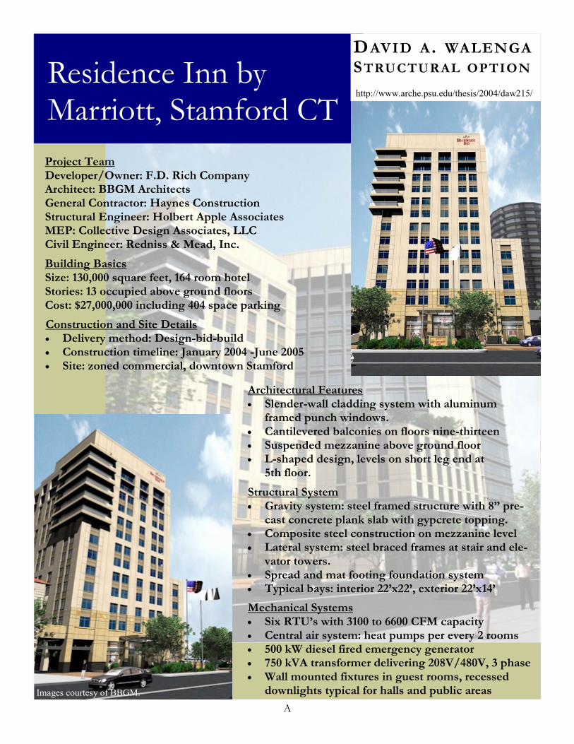
Project Team Developer/Owner: F.D. Rich Company Architect: BBGM Architects General Contractor: Haynes Construction Structural Engineer: Holbert Apple Associates MEP: Collective Design Associates, LLC Civil Engineer: Redniss & Mead, Inc.
Building Basics Size: 130,000 square feet, 164 room hotel Stories: 13 occupied above ground floors Cost: $27,000,000 including 404 space parking
Architectural Features • Slender-wall cladding system with aluminum
framed punch windows. • Cantilevered balconies on floors nine-thirteen • Suspended mezzanine above ground floor • L-shaped design, levels on short leg end at
5th floor.
Structural System • Gravity system: steel framed structure with 8” pre-
cast concrete plank slab with gypcrete topping. • Composite steel construction on mezzanine level • Lateral system: steel braced frames at stair and ele-
vator towers. • Spread and mat footing foundation system • Typical bays: interior 22’x22’, exterior 22’x14’
Mechanical Systems • Six RTU’s with 3100 to 6600 CFM capacity • Central air system: heat pumps per every 2 rooms • 500 kW diesel fired emergency generator • 750 kVA transformer delivering 208V/480V, 3 phase • Wall mounted fixtures in guest rooms, recessed
downlights typical for halls and public areas
Construction and Site Details • Delivery method: Design-bid-build • Construction timeline: January 2004 -June 2005 • Site: zoned commercial, downtown Stamford
Images courtesy of BBGM.
A

RESIDENCE INN BY MARRIOTT, STAMFORD CT
TABLE OF CONTENTS ABSTRACT A EXECUTIVE SUMMARY 2 BUILDING BACKGROUND 3 Basic Building Information 3 Architecture 3 Original Structure 4
Codes and Design Standards 8 Structural System Cost 8 System Advantages and Disadvantages 9
DEPTH STUDY: FLAT PLATE CONCRETE SYSTEM 9 Design Goals 9
System Background 9 Code Change and Loads 11 Gravity System 17 Lateral System 22 Mezzanine Hanger Anchor 26 System Cost 26 System Advantages and Disadvantages 27 Conclusions and Recommendation 28
BREADTH STUDY: MECHANICAL REDESIGN 29
Original System 29 Redesigned System 31 System Advantages and Disadvantages 33 Conclusion and Recommendation 33
BREADTH STUDY: PROJECT SEQUENCING AND SCHEDULING ANALYSIS 34
Introduction of Topic 34 Steel Scheduling and Sequencing 34 Flat Plate Scheduling and Sequencing 36 Conclusion and Recommendation 38
FINAL COMMENTS 39 ACKNOWLEDGEMENTS 40 REFERENCES 41 APPENDIX
AE SENIOR THESIS 1 DAVID WALENGA – SPRING 2004

RESIDENCE INN BY MARRIOTT, STAMFORD CT
EXECUTIVE SUMMARY
The Residence Inn by Marriott is a thirteen story hotel located in the heart of downtown
Stamford, Connecticut. The Residence Inn features 164 guest suites complete with kitchenettes and
comfortable sitting areas. Physically, the hotel is an “L” shaped structure with a step-in at the fifth
floor and cantilevered balconies on floors nine through thirteen. The Stamford Residence Inn
presents a unique situation: the construction of the building has been delay from January of this year
to June of this year in order to redesign certain systems of the building to lower the hotel’s first cost.
Therefore, one of the main focuses of this thesis is to research ways to lower the cost of the hotel
without lowering quality.
The focus of this report is devoted to analyzing and redesigning the hotel’s structural system
from a steel framed structure to a flat plate concrete system. Additionally, a redesign of the hotel’s
mechanical system is performed, and an analysis of the required scheduling and sequencing
associated with flat plate construction and steel with precast plank construction is also analyzed.
Based on the results and analysis of the structural redesign, it is concluded that a flat plate
concrete system is a more suitable alternative for the superstructure of the hotel. Taking into
account the recent volatile cost of steel, the need for supplemental fireproofing, and high cost of
precast plank the steel system is estimated to be almost six hundred thousands dollars more
expensive than the new flat plate design.
The results of the mechanical redesign show that changing the original system of heat pumps
to a system of packaged thermal air conditioners, PTAC’s, would lower the system first cost but also
lower the overall quality of the mechanical system. PTAC’s are louder, more expensive to operate
and require more maintenance than heat pumps, however, they would cost the owner about five
hundred thousand less at first cost than the original system. It is concluded that changing to
PTAC’s would lower the quality of the hotel too much and that other options for lowering the cost
of building should be entertained.
Analyzing the scheduling and sequencing involved with both the original and redesigned
structural systems concludes that for this project and under the assumptions made that flat plate
concrete requires considerably less preconstruction scheduling. It is also concluded that the
construction of the flat plate system will interfere less with the start and progress of other trades
than the original steel design.
AE SENIOR THESIS 2 DAVID WALENGA – SPRING 2004

Residence Inn by Marriott, Stamford CT
BUILDING BACKGROUND

RESIDENCE INN BY MARRIOTT, STAMFORD CT
BUILDING BACKGROUND Basic Building Information
Figure 1 – One Bedroom Suite
The site of the Residence Inn by Marriott is located in the heart of downtown Stamford Connecticut on the former site of a YMCA and a small one-story commercial building. The hotel has twelve floors of guest suites. Suites have either one or two bedrooms and come complete with kitchenettes. All total, there are 164 guest suites in the hotel creating approximately 130,000 square feet of space. Adjoining the hotel is a precast concrete parking garage with four hundred and four parking spaces. The garage is designed for future expansion of additional floors to accommodate the parking needs of an office building to be built next to the hotel. The estimated cost of the hotel and parking garage comes in at over $27 million dollars. However, the cost of the hotel and parking garage forced the owner, F.D. Rich Company, to delay the construction of the building by redesigning aspects of the building to lower the costs of construction. The original start of construction was to be January 2004 with completion to be in June 2005. Currently, construction is slated to begin in June of this year and anticipated completion is in November of 2005. Part of this thesis is focused on this delay in construction; with specific emphasis on the effectiveness of the delay and redesign on the overall cost of the hotel.
Architecture The Residence Inn is an ‘L’ shaped structure in plan with the short leg of the ‘L’ stepping in at the fifth floor. Architecturally, the building is both aand efficient in space utilization. A major design goal of the building, as with most buildings, is to maximize the amount of useable space the site offers. Hotels make money by renting space and an effectively designed hotel has as much rentable space as possible. The design of the Residence Inn creates an inviting and flowing plan for customers of the hotel. Some hotels can be confusing to navigate, however the Residence Inn avoids this pitfall and keeps the guests from wandering aimlessly in search of their room.
ppealing
AE SENIOR THESIS 3 DAVID WALENGA – SPRING 2004

RESIDENCE INN BY MARRIOTT, STAMFORD CT
Also featured in the hotel’s design is a suspended mezzanine level above the ground floor. By suspending this mezzanine, an access corridor, the ground floor has an open and grand feeling. Additionally, corner suites on floors nine through thirteen include a balcony that is cantilevered from the structure. The hotel is clad in Slenderwall, a prefabricated building skin system. The system includes a cold-formed steel frame with insulation and precast concrete facing. The precast concrete is cast to appear as actual stone. As a system, Slenderwall is efficient to erect, and to build. Slenderwall provides the look of stone without the cost of stone. Aluminum framed glazing completes the building skin. Original Structure -Gravity System The Residence Inn by Marriott was originally designed as a steel framed structure. Eight inch precast concrete plank creates the floor system with planks hollow in typical areas and solid in the mechanical and balcony areas. A ¾” gypcrete topping is used to finish the plank surface. This system is common for hotel structures because it easily applied to buildings with repetitive square bays and is quick to erect.
Project Team Owner/Developer: F.D. Rich Company Architect: BBGM Architects and Interiors Structural Engineer: Holbert Apple Associates, Inc. General Contractor: Haynes Construction M.E.P.:
Collective Design Associates, LLC
Civil Engineer: Redniss & Mead, Inc. Primary Tenet: Marriott
Typical spans in the hotel are 22’-0” and most non-typical spans are shorter than 22’-0”. Spans in the long leg of the structure span East-West and spans in the short leg of the building span North-South, as shown in Figure 2. The majority of beams are W14’s and W10’s while columns are W12’s and W10’s. A typical bay is shown in Figure 3. Shear connections are found throughout the structure except in the areas where beams are cantilevered and moment connections are required. The cantilevered balcony framing on floors nine through thirteen require moment connections. Composite construction is utilized for the suspended mezzanine level. This is done because composite steel is lighter than the concrete plank system used throughout the rest of the hotel. HSS sections are used as the tension members suspending the load of the mezzanine from the second floor. Composite steel construction also produces a shallower system depth than precast plank, thus providing a depth within the limits set architecturally for the mezzanine.
AE SENIOR THESIS 4 DAVID WALENGA – SPRING 2004

RESIDENCE INN BY MARRIOTT, STAMFORD CT
RESIDENCE INN BY MARRIOTT, STAMFORD CT
AE SENIOR THESIS 5 DAVID WALENGA – SPRING 2004
Figure 2 – 9th Floor PlanFigure 2 – 9th Floor Plan
AE SENIOR THESIS 5 DAVID WALENGA – SPRING 2004

RESIDENCE INN BY MARRIOTT, STAMFORD CT
Figure 3 – Typical Bay -Foundation System The foundation system for the Stamford Residence Inn is divided in two distinctive areas; each covering approximately half of the building’s overall footprint. The basement level slab elevation is twelve feet below grade and lies under the eastern half of the structure. The basement walls are designed to resist soil pressure and to carry the ground level slenderwall cladding system. Perimeter column foundations are spread footings and strip footings run between the spread footings to transfer the basement wall loads. The majority of the interior columns in the basement area transfer into mat foundations. Two main factors forced the use of mat footings. The first is the close proximity of the columns is not conducive to spread footings; therefore the use of mat footings would be more efficient. Secondly, the majority of the interior columns in the basement are part of the lateral system. A mat footing can resist overturning moments produced by lateral loads more effectively than spread footings as a result of the added mass. The ground floor foundation is very similar to the basement foundation. Gravity columns transfer loads to spread footings while the lateral system columns transfer to mat footings. The reasoning for the usage of mat and spread footings is the same as those in the basement. One primary difference between the ground level foundation system and the basement system is the allowable soil pressure. Foundations below the basement are on soils with an allowable pressure of 10 ksf whereas foundations below the ground floor sit on soils with an allowable pressure of 6 ksf. -Lateral System The primary lateral force resisting system of the hotel is concentrically located steel braced frames. In all, eight braced frames comprise the lateral system of the structure. Two frames are located at the western end of the structure while the balance of the frames are on the eastern side. Frames are located at the stairwells, elevator shafts and mechanical closet. See Figure 4 for the location of
AE SENIOR THESIS 6 DAVID WALENGA – SPRING 2004

RESIDENCE INN BY MARRIOTT, STAMFORD CT
frames and Figure 5 for a typical frame elevation. Locating the braced frames near the stairwells, elevator shafts and the mechanical closet is ideal because the braces are much less obtrusive to other elements of the building in these locations. Beam sizes for the lateral system range from W8’s to W18’s and columns are W12’s and W14’s. Bracing is achieved with hollow structural sections (HSS) and sizes vary from 12x8’s, 8x8’s, and 6x6’s. Using a system of braced frames for this building is a good choice over using moment frames because braced frames are generally cheaper than moment frames. The labor involved in moment frame connections tends to limit the scenarios where moment frames are more desirable than braced frames. 1 2 3 4
5 6
7 8
Figure 4 – Frame Locations Figure 5 –Typical Frame Elevation
AE SENIOR THESIS 7 DAVID WALENGA – SPRING 2004
RESIDENCE INN BY MARRIOTT, STAMFORD CT
Codes and Design Standards
1. “The BOCA National Building Code – 1996” 2. “State Building Code – 1999 Connecticut Supplement”
3. “State Building Code – 2000 Amendments to the Connecticut Supplement”
4. “Manual of Steel Construction – Load and Resistance Factor Design”, Volumes I and II,
Second Edition, 1994, American Institute of Steel Construction, Specifications for structural joints using ASTM A325 or A490 bolts, and AISC Code of Standard Practice.
5. “Minimum Design Loads for Buildings and Other Structures” (ASCE 7-95)
6. “Building Code Requirements for Structural Concrete, ACI 318-99,” American Concrete
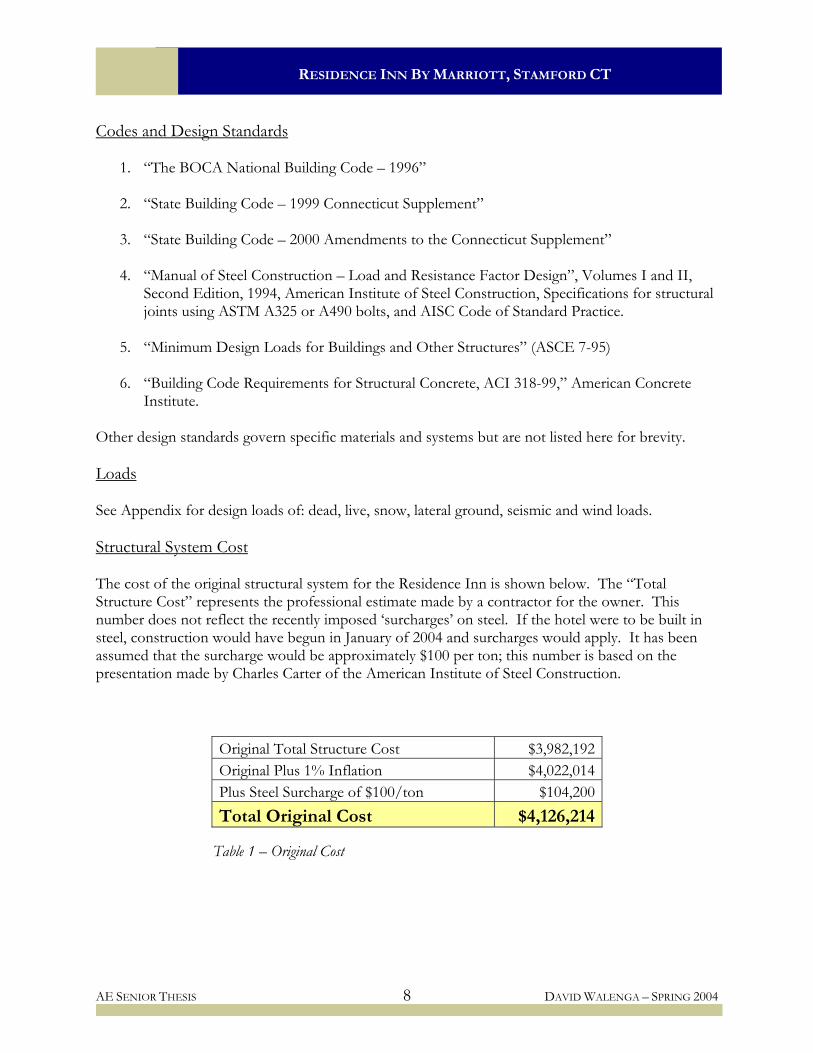
Institute. Other design standards govern specific materials and systems but are not listed here for brevity. Loads See Appendix for design loads of: dead, live, snow, lateral ground, seismic and wind loads. Structural System Cost The cost of the original structural system for the Residence Inn is shown below. The “Total Structure Cost” represents the professional estimate made by a contractor for the owner. This number does not reflect the recently imposed ‘surcharges’ on steel. If the hotel were to be built in steel, construction would have begun in January of 2004 and surcharges would apply. It has been assumed that the surcharge would be approximately $100 per ton; this number is based on the presentation made by Charles Carter of the American Institute of Steel Construction.
Original Total Structure Cost $3,982,192 Original Plus 1% Inflation $4,022,014 Plus Steel Surcharge of $100/ton $104,200 Total Original Cost $4,126,214
Table 1 – Original Cost
AE SENIOR THESIS 8 DAVID WALENGA – SPRING 2004

RESIDENCE INN BY MARRIOTT, STAMFORD CT
The cost above includes all footings, foundations, basement walls, slab on grade, and excavation in addition to the steel structure, roof and fireproofing. Steel construction costs have increased sharply over the last six months and are continuing to rise. The increases in cost have made steel less competitive, in terms of price, with concrete construction. A 1% percent inflation fee has been added to account for the approximate year since the estimate was made. System Advantages and Disadvantages Advantages
Lighter than concrete systems No shoring required Less steel to steel connections than alternate steel systems Erection in cold/inclement weather less problematic than systems with site cast concrete Overall system depth fits within allowable range
Disadvantages
Concrete plank and steel lead time could be an issue, requires additional coordination Recent trends increasing steel cost, particularly in the form of surcharges Vibration higher with concrete plank than site cast concrete slab systems High cost for precast concrete planks Fireproofing required on beams and columns Impact loading on plank causes acoustically poor condition
AE SENIOR THESIS 9 DAVID WALENGA – SPRING 2004
Residence Inn by Marriott, Stamford CT
DEPTH STUDY: FLAT PLATE CONCRETE SYSTEM
RESIDENCE INN BY MARRIOTT, STAMFORD CT
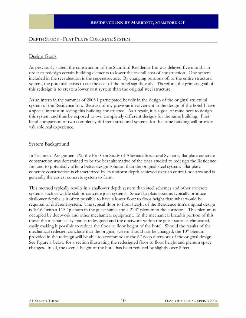
DEPTH STUDY - FLAT PLATE CONCRETE SYSTEM Design Goals As previously stated, the construction of the Stamford Residence Inn was delayed five months in order to redesign certain building elements to lower the overall cost of construction. One system included in the reevaluation is the superstructure. By changing portions of, or the entire structural system, the potential exists to cut the cost of the hotel significantly. Therefore, the primary goal of this redesign is to create a lower cost system than the original steel structure. As an intern in the summer of 2003 I participated heavily in the design of the original structural system of the Residence Inn. Because of my previous involvement in the design of the hotel I have a special interest in seeing this building constructed. As a result, it is a goal of mine here to design this system and thus be exposed to two completely different designs for the same building. First hand comparison of two completely different structural systems for the same building will provide valuable real experience. System Background In Technical Assignment #2, the Pro-Con Study of Alternate Structural Systems, flat plate concrete construction was determined to be the best alternative of the ones studied to redesign the Residence Inn and to potentially offer a better design solution than the original steel system. Flat plate concrete construction is characterized by its uniform depth achieved over an entire floor area and is generally the easiest concrete system to form. This method typically results in a shallower depth system than steel schemes and other concrete systems such as waffle slab or concrete joist systems. Since flat plate systems typically produce shallower depths is it often possible to have a lower floor to floor height than what would be required of different system. The typical floor to floor height of the Residence Inn’s original design is 10’-6” with a 1’-5” plenum in the guest suites and a 2’-3” plenum in the corridors. This plenum is occupied by ductwork and other mechanical equipment. In the mechanical breadth portion of this thesis the mechanical system is redesigned and the ductwork within the guest suites is eliminated, easily making it possible to reduce the floor to floor height of the hotel. Should the results of the mechanical redesign conclude that the original system should not be changed; the 10” plenum provided in the redesign will be able to accommodate the 6” deep ductwork of the original design. See Figure 1 below for a section illustrating the redesigned floor to floor height and plenum space changes. In all, the overall height of the hotel has been reduced by slightly over 8 feet.
AE SENIOR THESIS 10 DAVID WALENGA – SPRING 2004

RESIDENCE INN BY MARRIOTT, STAMFORD CT
Figure 1 – Plenum Section Code Change and Loads -Code Change Currently, the governing building code in the state of Connecticut is BOCA 1996. Connecticut plans on updating their governing code to IBC 2003 sometime in 2005. For the purposes of this project it is appropriate to use IBC 2000 as the design code. IBC 2000 has been selected as the design code for this study because it is currently the most used design standard in the United States. By changing from BOCA 1996 to IBC 2000 the most significant changes are in the lateral loading of the building. BOCA 1996 references the provisions in ASCE 7-95 and IBC 2000 references ASCE 7-98. The most noteworthy differences in ASCE 7-95 and ASCE 7-98 are the base wind speed and seismic acceleration factors for Stamford Connecticut. Changing codes increased the base wind speed from 80 mph to 110 mph. The acceleration factors and the method for determining the seismic response coefficient (Cs) are the primary differences in the seismic provisions of ASCE 7-95 and 98. There are other subtle differences in the seismic portion, but the basic methods are the same. See the wind and seismic load portions of this section for the results of the load calculations using IBC 2000. -Dead Loads Section 1606 of the 2000 edition of the International Building Code governs the application of dead loads in structural system design. The code specifies that the building’s material weights be used in design. Below is listed material weights used in design here as well as additional superimposed loads. Dead loads are based on industry standards and assumptions. Applied loads of known materials and finishes are as follows:
AE SENIOR THESIS 11 DAVID WALENGA – SPRING 2004

RESIDENCE INN BY MARRIOTT, STAMFORD CT
Reinforced concrete slab – 9” 110 psf
Reinforced concrete 150 pcf MEP, miscellaneous, ceiling: 10 psf Partitions: 20 psf Stone flooring system (ground floor): 150 psf Miscellaneous balcony weight: 5 psf Roof ballast: 13 psf Roof membrane and insulation: 7 psf Metal roof deck: 2 psf Mechanical roof top units: 25 psf (applicable bays only) Exterior slenderwall assembly: 36 psf of wall Elevator machine room 10” slab: 125 psf
Superimposed dead loads: Roof: 10 psf Floors: 10 psf -Live Loads Section 1607 of IBC 2000 includes the provisions governing live loads and live load reduction. Listed below are the applicable live loads for the Residence Inn. Balcony-100 psf Lobbies -100 psf Corridors-100 psf Guest rooms-40 psf Stairs-100 psf Live load reduction – 1607.9 (Equation. 16-1)
⎟⎟⎠
⎞⎜⎜⎝
⎛+=
TLLo AKLL 1525.0
AT is the tributary area of the column.
KLL is: 4 for interior columns 4 for exterior columns without cantilevered slabs 3 for exterior columns with cantilevered slabs 2 for corner columns with cantilevered slabs L is limited to 0.5Lo for columns supporting only one floor and to 0.4 Lo for columns supporting more than one floor.
AE SENIOR THESIS 12 DAVID WALENGA – SPRING 2004

RESIDENCE INN BY MARRIOTT, STAMFORD CT
-Snow Load Snow loads are governed by chapter 7 of ASCE 7-98 and Section 1608 of IBC 2000. The hotel’s roofs are flat and there are no sloped roofs on the project, therefore no sloped roof calculations need to be performed. Factors and values as per code: Ground snow load: 30 psf Flat roof snow load: 30 psf Snow exposure factor (Ce): 0.7 Thermal factor (CT): 1.0 Snow importance factor (I): 1.0 Flat roof snow load used for drifting calculations (Pf =CTCeIPg): 21 psf Average drifted snow loads: Penthouse roof to main roof (25’):
Pd= 40 psf hd= 1.68 feet wd= 4.5 feet
Main roof to 6th floor roof (86’): Pd= 54.2 psf hd= 3.2 feet wd= 8.9 feet
Main roof to loading dock roof (126’): Pd= 59.8 psf hd= 3.8 feet wd= 10.6 feet
-Wind Loads Wind loading is determined following the requirements of IBC 2000, Section 1609, as well as data from the 1999 Connecticut Supplement to BOCA. Site-location specific factors governing the design are as follows:
1. Basic wind speed, V: 110 mph 2. Importance factor, I: 1.0 3. Building Exposure Class: B
AE SENIOR THESIS 13 DAVID WALENGA – SPRING 2004

RESIDENCE INN BY MARRIOTT, STAMFORD CT
East - West Wind Loading
Figure 2 –E-W Pressure Profile
Figure 3 –E-W Shear Loading
AE SENIOR THESIS 14 DAVID WALENGA – SPRING 2004

RESIDENCE INN BY MARRIOTT, STAMFORD CT
North – South Wind Loading
Figure 4 –N-S Pressure Profile
Figure 5 – N-S Shear Loading
AE SENIOR THESIS 15 DAVID WALENGA – SPRING 2004

RESIDENCE INN BY MARRIOTT, STAMFORD CT
Total base shears: East-West Direction: 422 kips North-South Direction: 633 kips Compared to the wind loads of the original design determined using BOCA 1996, the wind loading using IBC 2000 is higher. This increase is mostly caused by changing the base wind speed from 80 miles per hour to 110 miles per hour. In terms of a percentage, the east-west total base shear increased by 8% while the base shear in the north-south direction increased by 30%. Wind loading significantly increased despite lowering the overall height of the building by fifteen feet. -Seismic Loads By changing design codes from BOCA 1996 to IBC 2000, the seismic loading on the Residence Inn increased. The increase is due in part to changing from a steel structure to a concrete structure because concrete structures weigh more than steel structures. The building weight of the steel structure was about 19,000 kips, while the weight of the concrete structure is roughly 24,200 kips, a 27% increase. Table 1 below summarizes the results of the seismic load calculations.
Level H (ft) hx wx wxhxk Cvx Fx (kip)
14 18.0 155.8 292 119194 0.03 26.76 13 12.5 137.8 1432 504993 0.13 113.37 12 9.75 125.3 1547 487286 0.13 109.40 11 9.75 115.5 1547 442456 0.12 99.33 10 9.75 105.8 1547 398343 0.11 89.43 9 9.75 96.0 1547 355001 0.09 79.70 8 9.75 86.3 1547 312492 0.08 70.16 7 9.75 76.5 1508 264042 0.07 59.28 6 9.75 66.8 1508 224472 0.06 50.39 5 9.75 57.0 1626 200506 0.05 45.01 4 9.75 47.3 1739 171483 0.05 38.50 3 9.75 37.5 1739 130224 0.03 29.24 2 9.75 27.8 1739 90983 0.02 20.43 1 18.0 18.0 2125 66425 0.02 14.91
∑wihi
k = 3767899 1.00 846
Table 1 – Seismic Story Shears
Total base shear (V): 846 kips Base shear of the original design: 665 kips Percent Increase: 27%
AE SENIOR THESIS 16 DAVID WALENGA – SPRING 2004

RESIDENCE INN BY MARRIOTT, STAMFORD CT
-Load Combinations
Load combinations are found in Section 1605 of IBC 2000. 1.4D 1.2D+1.6L+0.5(Lr or S or R) 1.2D+1.6(Lr or S or R) + (fL or 0.8W) 1.2D+ 1.6W +fL+0.5(Lr or S or R) 1.2D+1.0E+fL+f2S 0.9D+(1.0E or 1.6W)
Gravity System -Slab Design In Technical Assignment #2, it was determined that an eight in slab would be sufficient for a flat plate system, in the typical bays. However, after further investigation it has been determined that a nine inch slab would be required. For this thesis, the design of the typical bays is being performed and non-typical slabs are only checked for minimum slab depth. The typical bays that have been designed here account for roughly 60% of the structure’s floor area. Several slabs on the eastern end of the structure, in the area of the larger two bedroom suites and near the cantilevered balconies on the ninth through thirteenth floors, need a nine inch slab. Larger bays are also found on the north east side of the structure; the ‘short-leg’ of the structure. Applying a nine inch slab over the entire floor area simplifies forming and also eliminates the need for supplemental shear reinforcement, such as shear rails, from being required. It is more expensive to need additional shear reinforcement than to have a slab one inch thicker in depth. To design the slab for the Residence Inn, ADOSS was used to obtain design moments. ADOSS does not calculate all positive moments, so those were calculated separately, by hand. Design Assumptions:
f’c = 3000 psi Fy = 60 ksi Weight of concrete = 150 pcf Applied loads: Dead load: 50 psf Live load: 100 psf – required only in corridor but applied everywhere Wall load: 342 plf
AE SENIOR THESIS 17 DAVID WALENGA – SPRING 2004

RESIDENCE INN BY MARRIOTT, STAMFORD CT
-Typical 19’ Wide Bay
Mu b d As Min. As Reinforcement Span Location (ft-kips) (in) (in) (in2) (in2) End Spans
Ext. Neg 19 88 7.75 0.61 1.43 8 No. 5 @ 12" Column Strip Positive 86 88 7.75 2.77 1.43 9 No. 5 @ 10"
Int. Neg 143 88 7.75 4.61 1.43 8 No. 7 @ 10" Ext. Neg 0 140 7.75 0.00 2.27 12 No. 5
Middle Strip Positive 60 140 7.75 1.94 2.27 12 No. 5 Int. Neg 48 140 7.75 1.55 2.27 12 No. 5
Interior Span Column Strip Positive 72 88 7.75 2.32 1.43 8 No. 5 @ 12" Middle Strip Positive 163 140 7.75 5.26 2.27 12 No. 5 @ 12"
Table 1 - !9’ Wide Bay Design Summary
Moments were calculated using 40 psf live load in the suites and 100 psf live load in the corridor and the design was found to be mostly controlled by minimum steel. Therefore, moments were calculated using 100 psf live and found that only a minimal amount of steel had to be added over the previous trial design. Designing for 100 psf live load over the area of the floor adds value to the building in case someday the floor plan of the structure is changed. The design summary of the typical 19’-0” wide bays is summarized above in Table 1. As shown in Table 1, reinforcement in the end spans is governed by minimum reinforcement. For constructability reasons, No. 4 bars are not used because they are not capable of supporting the load of construction workers walking on the reinforcing mats. Additionally, bar sizes are skipped in order to make differing sizes obvious to the workers in the field. It is easier to visually tell the difference between a No. 5 and a No. 7 than the difference between a No. 5 and a No. 6. Spacing is not specified for the end spans’ middle strip because it is assumed the bars will be distributed evenly.
AE SENIOR THESIS 18 DAVID WALENGA – SPRING 2004

RESIDENCE INN BY MARRIOTT, STAMFORD CT
-Typical 22’ Wide Bay
Mu b d As Min. As Reinforcement Span Location (ft-kips) (in) (in) (in2) (in2) End Span
Ext. Neg 14 88 7.75 0.45 1.43 8 No. 5 @ 12" Column Strip Positive 60 88 7.75 1.94 1.43 9 No. 5 @ 10"
Int. Neg 99 88 7.75 3.19 1.43 8 No. 7 @ 10" Ext. Neg 0 177 7.75 0.00 2.87 12 No. 5
Middle Strip Positive 44 177 7.75 1.42 2.87 12 No. 5 Int. Neg 33 177 7.75 1.06 2.87 12 No. 5
Interior Span Column Strip Positive 58 88 7.75 1.87 1.43 8 No. 5 @ 12" Middle Strip Positive 112 177 7.75 3.61 2.87 15 No. 5 @ 12"
Table 2 – 22’ Wide Bay Design Summary
In table 2 above the design of the typical 22’-0” wide bays is summarized. The same design assumptions and processes were followed here as before with the 19’-0” wide bay. -Edge Beam Design The design of the edge beams is assumed to be controlled by lateral loading, as the edge beams are the beam portion of the hotel’s moment frames. Inspection of the output produced by ADOSS and a quick hand calculation check shows moments, torsion and shear loading from the gravity slab system will not control the design of the beams. The reinforcement required to sustain lateral loading is greater than what will be needed for gravity loads alone. The cross sectional area used in calculations is 14” x 14”.
AE SENIOR THESIS 19 DAVID WALENGA – SPRING 2004

RESIDENCE INN BY MARRIOTT, STAMFORD CT
-Column Design To design the columns of the gravity system a load takedown table was created using an Excel spreadsheet to obtain the axial loads at each floor height. Column moments are obtained from the ADOSS models of the slab design. For simplicity, and to obtain a relatively accurate representation of the columns needed for the hotel, columns are not designed for every floor but for the thirteenth, ninth, fifth and ground floors. Performing the design in this manner quickly shows how column sizes will vary with floor height. Exterior columns are designed here for gravity loading and will be checked for lateral loading when the lateral system is designed; the final design of the exterior columns will be determined once lateral effects are taken into account. To perform the design of the columns, axial loads are imputed into PCA Column along with moments obtained from ADOSS. Similar to ADOSS, the load factors in PCA Column have to be updated to current design code. The designs of PCA Column were cross-check with the 2002 CRSI design handbook. The design of typical interior and exterior columns is shown below in Tables 3 and 4.
Typical Exterior Column
Floor Design 13th 14" x 14" 8 #5 w/ #3 T @ 16" 9th 16" x 16" 8 #6 w/ #3 T @ 16" 5th 18" x 18" 8 # 8 w/ #4 T @ 16" Ground 22" x 22" 8 #10 w/ #4 T @ 16"
Table 3 – Typical Exterior Column Design
Typical Interior Column
Floor Design 13th 14" x 14" 8 #5 w/ #3 T @ 16" 9th 18" x 18" 8 #6 w/ #3 T @ 16" 5th 20" x 20" 8 #8 w/ #4 T @ 16" Ground 22" x 22" 12 #10 w/ #4 T @ 16"
Table 4 – Typical Interior Column Design
AE SENIOR THESIS 20 DAVID WALENGA – SPRING 2004

RESIDENCE INN BY MARRIOTT, STAMFORD CT
Typical 22’ Wide Bay Plan
9” Slab Edge Beam Figure 1 – 22’ Wide Bay Plan Foundation System In almost all cases, comparison of a steel framed structure to a concrete framed structure for the same building usually yields the result of either a larger or sometimes a different foundation system needed to support the concrete system versus the steel system. This is simply due to the fact that concrete systems weigh more than steel systems. The foundation for the Residence Inn is indeed affected by the increased weight of the concrete structure. By changing the structure to concrete, the overall weight of the hotel increased by 27%. As discussed in the Building Background portion of this report, the majority of the foundation system of the original design is a spread footing system. The remaining portions of the foundation are mat foundations. The three mat foundations are location in the regions of the steel braced frames. One mat foundation is located at the west stair/elevator tower and another is located at the west elevator bank. Columns are closely spaced here and by simple inspection it is fair to assume that even without the presence of the steel braced frames that mat foundations would still be required here. The third mat foundation supports frame No. 8, see Figure on Page 7, and will not be needed for the redesigned structure since the frame is removed. Inspection of the original design shows that there is adequate room to increase the area of the footings, if necessary, in order to transfer the additional concrete system load. To get an idea of the changes necessary to support the concrete structure, a typical interior and exterior spread footing were designed and compared to the original design.
AE SENIOR THESIS 21 DAVID WALENGA – SPRING 2004
RESIDENCE INN BY MARRIOTT, STAMFORD CT
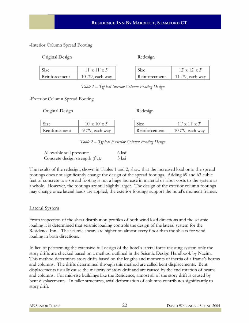
-Interior Column Spread Footing
Original Design Redesign Size 11' x 11' x 3' Size 12' x 12' x 3' Reinforcement 10 #9, each way Reinforcement 11 #9, each way
Table 1 – Typical Interior Column Footing Design
-Exterior Column Spread Footing
Original Design Redesign Size 10' x 10' x 3' Size 11' x 11' x 3' Reinforcement 9 #9, each way Reinforcement 10 #9, each way
Table 2 – Typical Exterior Column Footing Design
Allowable soil pressure: 6 ksf Concrete design strength (f’c): 3 ksi The results of the redesign, shown in Tables 1 and 2, show that the increased load onto the spread footings does not significantly change the design of the spread footings. Adding 69 and 63 cubic feet of concrete to a spread footing is not a huge increase in material or labor costs to the system as a whole. However, the footings are still slightly larger. The design of the exterior column footings may change once lateral loads are applied; the exterior footings support the hotel’s moment frames. Lateral System From inspection of the shear distribution profiles of both wind load directions and the seismic loading it is determined that seismic loading controls the design of the lateral system for the Residence Inn. The seismic shears are higher on almost every floor than the shears for wind loading in both directions. In lieu of performing the extensive full design of the hotel’s lateral force resisting system only the story drifts are checked based on a method outlined in the Seismic Design Handbook by Naeim. This method determines story drifts based on the lengths and moments of inertia of a frame’s beams and columns. The drifts determined through this method are called bent displacements. Bent displacements usually cause the majority of story drift and are caused by the end rotation of beams and columns. For mid-rise buildings like the Residence, almost all of the story drift is caused by bent displacements. In taller structures, axial deformation of columns contributes significantly to story drift.
AE SENIOR THESIS 22 DAVID WALENGA – SPRING 2004

RESIDENCE INN BY MARRIOTT, STAMFORD CT
The decision use this method of analysis was made because story drifts almost always control the design of a lateral resisting system. Obviously, a more extensive study will have to be performed to obtain the final design of the lateral system. The purpose of this study is to determine if the cross sectional areas of the previously designed columns and edge beams are sized appropriately to control story drifts. Table 9.5.2.8 in ASCE 7-98 outlines the limitations for allowable story drifts. According to Table 9.5.2.8 the allowable story drift for the Residence Inn is 0.02hsx, where hsx is the height of the floor below the floor in question. Table 1 below shows the allowable story drifts for the Residence Inn.
h (ft) ∆a (in) Col. Size Penthouse Roof 18.00 4.32 14 x 14 Penthouse Floor 12.50 3.00 14 x 14 13th Floor 9.75 2.34 16 x 16 12th Floor 9.75 2.34 16 x 16 11th Floor 9.75 2.34 16 x 16 10th Floor 9.75 2.34 16 x 16 9th Floor 9.75 2.34 16 x 16 8th Floor 9.75 2.34 18 x 18 7th Floor 9.75 2.34 18 x 18 6th Floor 9.75 2.34 18 x 18 5th Floor 9.75 2.34 22 x 22 4th Floor 9.75 2.34 22 x 22 3rd Floor 9.75 2.34 22 x 22 2nd Floor 18.00 4.32 22 x 22
Based on the previously pesize has been assumed and The equation used to dete
∆bi
Where: ( )igK∑ is the sum
is the sum( icK∑ ) I denotes the mom
AE SENIOR THESIS
Table 1 – Allowable Story Drifts and Column Sizes
rformed design of the columns a distribution of column cross-sectional is shown in Table 1 above.
rmine the bent drift per story is:
( )( ) ( ) ⎥
⎥⎦
⎤
⎢⎢⎣
⎡
∑+
∑∑
=icig
ii
KKEhV 11
12
2
Equation 1
mation of gigi LI for all beams.
mation of ici hI for all columns. ent of inertia of either the columns or beams.
23 DAVID WALENGA – SPRING 2004

RESIDENCE INN BY MARRIOTT, STAMFORD CT
Table 2 – Bent-Action Drift Calculation
he bent-action story drifts are calculated and summarized in Table 2 below.
V (kips) Lg t) I Bms. ∑ ) ∑ . ∑
T
h h ∑V (f (Ig/Lg I Cols (Ic/h) ∆bi Drift (ft.) (in.) Story (kips) (in4) (in3) (in4) (in3) (in.) (in.) 14 18.00 216 26.8 26.8 445 3201 437 86436 400 0.1222 6.77 13 12.50 150 113.4 140.1 445 3201 437 86436 576 0.2594 6.65 12 9.75 117 109.4 249.5 445 3201 437 147456 1260 0.2153 6.39 11 9.75 117 99.3 348.9 445 3201 437 147456 1260 0.3009 6.18 10 9.75 117 89.4 438.3 445 3201 437 147456 1260 0.3781 5.88 9 9.75 117 79.7 518.0 445 3201 437 147456 1260 0.4469 5.50 8 9.75 117 70.2 588.1 445 3201 437 147456 1260 0.5074 5.05 7 9.75 117 59.3 647.4 445 3201 437 236196 2019 0.5045 4.54 6 9.75 117 50.4 697.8 485 3201 401 236196 2019 0.5839 4.04 5 9.75 117 45.0 742.8 485 3201 401 236196 2019 0.6216 3.46 4 9.75 117 38.5 781.3 485 3201 401 527076 4505 0.5940 2.83 3 9.75 117 29.2 810.6 485 3201 401 527076 4505 0.6162 2.24 2 9.75 117 20.4 831.0 485 3201 401 527076 4505 0.6318 1.62 1 3201 401 527076 3660 0.9925 0.99 18.00 144 14.9 845.9 485 * 2/3 of the first floor height is used in
. Had
imensions of the members may have to be increased to meet flexural and ductility requirements.
calculation.
Based on the calculations above, the story drifts of every level of the Residence Inn are within the allowable range governed by ASCE 7-98. By keeping within the allowable limits of story drift the primary goal of this study has been achieved. The intention here was to ensure that the designed and assumed column sizes, as well as the edge beam size, are adequate to determine story drifta more extensive analysis been performed, the reinforcement and possibly the cross sectional d
AE SENIOR THESIS 24 DAVID WALENGA – SPRING 2004

RESIDENCE INN BY MARRIOTT, STAMFORD CT
Mezzanine Hanger Anchor Mezzanine Tension Member Anchors The mezzanine level of the Residence Inn is hung from the second floor. The original design for the structure designed the mezzanine level as composite steel construction to achieve a lightweight and shallow system. To achieve the same properties, the mezzanine level will remain composite steel in the redesign. One side of the mezzanine rests on a concrete wall and the other is suspended by HSS members to the second floor. See Figure 1 for a partial plan. In the original design, the HSS tension members were connected to the second floor beams via a tab welded into the column and to the beam. Here, anchor bolts will have to be cast into the second floor slab and plates will be welded to the top of the HSS mto receive the bolting.
embers
Appendix D of ACI 318-02 governs the design of tensile anchorage to concrete. Following the provisions in Appendix D, it is determined that geometry of the HSS section controls the design. Assuming four, 5” hooked anchor bolts and a 10” x 10” plate, the breakout strength of the concrete is on the order of 90 kips. A tensile load of about 10 kips is applied to the connection, which is about nine times less than the breakout strength. In order to achieve proper edge distances and meet design requirements of the steel plate, the plate has to be 10” x 10”.
Figure 1 – Partial Mezzanine Plan
Design summary: 10” x 10” x ½” A36 plate (4) 5” ½ φ anchor bolts 3/16” fillet weld See Figure 2 at right for connection detail. Figure 2 – Anchor Connection Detail
AE SENIOR THESIS 25 DAVID WALENGA – SPRING 2004

RESIDENCE INN BY MARRIOTT, STAMFORD CT
Structural System Cost Two of the biggest issues that must be considered in the determination of what type of structural system to use for a project are time of construction and cost. System cost will be analyzed here; and scheduling and construction time are discussed in the Project Sequencing and Scheduling Analysis portion of the report. Many factors go into determining the cost of a building and its structural system. Location of the project influences the costs of both labor and material. Stamford Connecticut is a city with a population of 120,000 people located within 40 miles of New York City. According to R.S. Means, a construction cost reference series, the cost of construction, including labor and material, is 11% higher than the national average in Stamford. Given the close proximity to New York, it is not at all surprising that the cost of construction in Stamford is higher than the national average. To keep continuity between the original estimate and the new estimate, the cost of: slabs on grade, basement and foundation excavation, and basement construction were kept the same as the original but with 1% added for the cost of inflation since the original estimate was made. As reported in the Foundations portion of the redesign, the size of the foundations increased somewhat from the original design. The cost of this increase was estimated using the original cost’s unit prices; once this was done the increase was added to the original cost. The estimation of the concrete superstructure was performed using the MC^2 software package. An estimate of column length, beam length and slab area was performed and all necessary material data was entered. Specifically, concrete design strengths, steel grades, common reinforcing sizes were entered into MC^2. Once a price was obtained a rough check was performed using RS Means. This was done to ensure that the estimation is relatively accurate. The total cost of the flat plate system is summarized in Table 1 below.
Basement Excavation $225,092 Foundations $391,215 Miscellaneous Steel $3,000 Slabs on grade and Basement construction $271,510 Flat plate system cost $2,650,000 Total $3,540,817
Table 1 – Flat Plate System Cost
AE SENIOR THESIS 26 DAVID WALENGA – SPRING 2004

RESIDENCE INN BY MARRIOTT, STAMFORD CT
The cost difference summary between the steel system and the redesigned flat plate system is summarized below in Table 2. Taking into account the current volatile state of the cost of steel the flat plate system is almost $600,000 less than steel system. Removal of the steel surcharge would decrease the difference in cost by 22% to roughly $480,000.
Original Total Structure Cost $3,982,192 Original Plus 1% Inflation $4,022,014 Plus Steel Surcharge of $100/ton $104,200 Total Original Cost $4,126,214 Flat Plate Cost $3,540,817
Cost Difference $585,397
Table 2 – Cost Difference of Flat Plate System Clearly, based on the estimations performed, the flat plate concrete system is more cost efficient than the steel system. A portion of the cost difference can be attributed to the elimination of supplementary fire-proofing needed in the flat plate concrete system. The cost associated with fireproofing the steel system is estimated at just over $360,000. The cost of fireproofing coupled with the steel surcharges accounts for 62% of the cost difference between systems. To determine if the actual cost difference between the two a more detailed and professional estimate should be performed. However, based on the assumptions made and the methods of estimation, this estimate is accurate enough to show that the flat plate system costs less than the original design. System Advantages and Disadvantages Advantages
Simple, reusable formwork Simple reinforcement layout Only 9 inches total depth Less vibration and walking impact noise than concrete plank system No fireproofing required Not affected by recent steel surcharges Significantly cheaper than the steel system
Disadvantages
Heavier than steel system – Increased foundation size and seismic loads Shoring required Concrete construction heavily effected by weather More field labor required than steel system
AE SENIOR THESIS 27 DAVID WALENGA – SPRING 2004

RESIDENCE INN BY MARRIOTT, STAMFORD CT
Conclusions and Recommendation Conclusions A point by point list of conclusions:
The flat plate concrete system is considerably cheaper, almost $600,000, than the original steel with precast plank design. Much of this cost difference is due in part to the recent trends in the cost of steel and need for supplemental fireproofing on steel.
Despite being heavier than the steel system, the flat plate concrete system does not have
considerably larger foundations than the original design.
Although the weather can affect the progress of concrete construction it has been concluded through preliminary schedules that the construction of the concrete structure will be completed prior to the arrival of project delaying cold weather in Connecticut.
Recommendation
Based on the conclusions above and the research performed here, it is concluded that the flat plate concrete structural system is a better design alternative than the steel system. Therefore, it is recommended that flat plate concrete be the structural system for the Residence Inn by Marriott in Stamford, Connecticut.
AE SENIOR THESIS 28 DAVID WALENGA – SPRING 2004

Residence Inn by Marriott, Stamford CT
BREADTH STUDY: MECHANICAL REDESIGN

RESIDENCE INN BY MARRIOTT, STAMFORD CT
BREADTH STUDY - MECHANICAL REDESIGN Design Goals As previously mentioned, the construction of the Residence Inn was delayed by the cost of construction. One way to lower the first cost of the structure has been determined is to change the type of mechanical system located within the building. The owner is willing to sacrifice some level of building quality in order achieve this goal. Therefore, it has been determined that packaged thermal air conditioners, through-wall units, are a good alternative to the original mechanical system utilized in the guest suites. The mechanical system in the non-guest suite portions of the hotel will remain unchanged. Original System System Background The original system designed for the Residence Inn allows guests to control the heating and cooling in their rooms via a system of heat pumps located in every room. Roof top units provide the necessary air distribution and circulation to the guest rooms. In addition to the roof top units located on the roof and penthouse roof, three boilers and two cooling towers are also located on the mechanical roof levels. This system provides a high level of comfort at low operating cGuests have the ability to accurately control their comfort level anto maintain an even comfort level throughout their suite. However, the system’s first cost is high; compared to other systems.
osts. d
Hot and cold water is pumped from the roof to the individual heat pump units located in the guest suites in order to heat or cool the rooms. Air is ducted from the roof top units to the heat pumps where it is conditioned and ducted throughout the room. System Equipment Cost To estimate the cost of the original system, a cost estimate prepared by a general contractor during the design phase of the original building is used. Below, in Figure 1, is the estimated quantity and cost of the equipment necessary to condition the guest suites. The costs include labor and other markups such as contractor overhead and profit. The costs of the equipment needed to condition the remaining spaces in the hotel are excluded from the estimate since that equipment will be unchanged by the redesign.
AE SENIOR THESIS 29 DAVID WALENGA – SPRING 2004

RESIDENCE INN BY MARRIOTT, STAMFORD CT
Item Qty. Unit Unit Cost Cost Gas Fired Boiler 1800 mbh - complete 3 ea 36,000.00 108,000.00 225 Ton Cooling Tower - complete 2 ea 25,000.00 50,000.00 Package Heat Pumps 188 ea 1,700.00 319,600.00 7320 cfm RTU 1 ea 26,000.00 26,000.00 2000 cfm RTU 1 ea 10,000.00 10,000.00 1200 cfm RTU 5 ea 6,500.00 32,500.00 Air distribution devices 300 ea 110.00 33,000.00 Fire dampers 188 ea 65.00 12,220.00 Access doors 188 ea 60.00 11,280.00 Galvanized sheet metal ductwork 8000 lbs 6.75 54,000.00 Ductwork Insulation 3000 sf 2.00 6,000.00 Boiler and water heater flue breeching 1 ls 7,500.00 7,500.00 Hot water piping 3500 lf 25.00 87,500.00 Condenser water piping 2800 lf 20.00 56,000.00 Drain piping 500 lf 15.00 7,500.00 RTU hook-up 13 ea 15,000.00 195,000.00 Cooling tower balancing 2 ea 100.00 200.00 Boiler balancing 3 ea 150.00 450.00 RTU balancing 13 ea 150.00 1,950.00 Heat pump balancing 188 ea 50.00 9,400.00 Rigging 1 ls 40,000.00 40,000.00 Total $1,068,100.00 Original System Complete Cost $2,015,210.00 System Cost of guest suite equipment $1,068,100.00 Cost of non-suite related system $947,110.00
Figure 1 –Original System Cost System Advantages and Disadvantages Advantages: Disadvantages: - High level comfort control - High first cost - Quiet operation - More equipment required - Low operating costs - More difficult to maintain - More durable
AE SENIOR THESIS 30 DAVID WALENGA – SPRING 2004

RESIDENCE INN BY MARRIOTT, STAMFORD CT
Redesigned System System Background A system of packaged thermal air conditioners, PTAC’s, was selected as an alternative mechanical system to the original design. More commonly known as through-wall units, PTAC’s involve much less equipment to operate and therefore less labor to install than the hotel’s original system.
The use of PTAC’s is common in hotel construction for several reasons. First, by having a unit or multiple units in a guest suite, the guest is capable of easily controlling their own comfort. Secondly, if a mechanical failure were to occur the hotel would not lose the ability to rent out several rooms but only one. In the event of a mechanical failure, the hotel could also have backup PTAC units on hand to quickly replace a down unit in order to keep the room rentable.
Carrier’s Premier Series 52P, shown above, was selected as the PTAC for the redesign. The Premier Series offers heating and cooling in a single package. The unit features a heat pump and an electric heater. The electric heater is used when outdoor coil temperatures drop below 20° F and the heat pump operates when outdoor coil temperatures are above 20° F. By including a heat pump and an electric heater the Premier Series is more efficient than PTAC’s that have only an electric heater. Electric heaters are less efficient than heat pumps and by limiting the need for the electric heater the Carrier Premier Series is more efficient. Operation from heat pump and electric heater is automatically controlled. The design of the PTAC system was aided by Carrier’s Hourly Analysis Program, version 4.2 (HAP). The hotel features three different guest suites: one bedroom with a partition between the sleeping and living area, one bedroom without a wall between the sleeping and living area, and a two bedroom suite with partitions dividing the spaces. Five spaces were modeled in HAP to calculate the heating and cooling loads needed to select a PTAC size. A single unit has been selected for all spaces. The demands fit within this units operating range, therefore the unit is not either over or undersized. The model selection chart is shown in Figure 2 below with the selected model highlighted.
AE SENIOR THESIS 31 DAVID WALENGA – SPRING 2004

RESIDENCE INN BY MARRIOTT, STAMFORD CT
AE SENIOR THESIS 32 DAVID WALENGA – SPRING 2004
Figure 2 –PTAC Unit Selection Chart
Figure 3 –PTAC System Cost
System Equipment Cost The estimate for the PTAC was performed by looking up unit prices online and applying installation costs and other construction related costs such as overhead and profit. The original system included 188 units; however the PTAC system requires a unit for each room within the guest suites.
Item Qty. Unit Unit Cost Cost Packaged thermal air conditioners 269 ea 1,300.00 349,700.00 Electrical hookup 269 ea 60.00 16,140.00 Air filters 269 ea 15.00 4,035.00 Optional thermostats 269 ea 100.00 26,900.00 Architectural Louvers 269 ea 350.00 94,150.00 Total $490,925.00
Non-suite related system cost from original design $947,110.00
Total system cost $1,438,035.00 First cost system savings $577,175.00

RESIDENCE INN BY MARRIOTT, STAMFORD CT
System Advantages and Disadvantages Advantages:
More flexible/lower design cost Lower mechanical failure impacts Much less equipment required Lower upfront cost
Disadvantages:
Lack of ducting lowers quality of distribution Affects architectural design of exterior: louvers Higher operating costs Higher noise operation level
Conclusions and Recommendation Conclusions A point by point list of conclusions:
The PTAC system has a considerably lower first cost than the original design. Although cheaper than the original design, the PTAC system is a lower quality system in that
the controllability and comfort level in the rooms is lower than the original design. The PTAC system also operates at a higher decibel level than the heat pump system.
The PTAC system would significantly change the appearance of the exterior architecture of
the hotel by adding louvers at the location of each unit. Recommendation
The owner of the Residence Inn has the desire to lower the first cost of the building. Presented here was one way to lower the first cost. However, by changing to PTAC’s the quality of the mechanical system is lowered and the architecture of the building is negatively impacted. Over the life cycle of the building, PTAC’s will cost more than the original design. Therefore, it is recommended that the owner not change the mechanical system of the Residence Inn and in turn find another way to lower the first cost of the building.
AE SENIOR THESIS 33 DAVID WALENGA – SPRING 2004

Residence Inn by Marriott, Stamford CT
BREADTH STUDY: PROJECT SEQUENCING AND
SCHEDULING ANALYSIS

RESIDENCE INN BY MARRIOTT, STAMFORD CT
BREADTH STUDY: PROJECT SEQUENCING AND SCHEDULING ANALYSIS Introduction of Topic Cost and system performance do not solely dictate which type of structural system is best suited for a project. From a structural engineering standpoint, many design solutions can be established as a solution for a particular building. Two very viable structural design solutions have been presented in this report already. In technical assignment number two, two other design solutions were also presented in the form of a concrete waffle slab system and a steel form deck system. However, the mere capability to design a system that satisfies the given set of design criteria of codes and system limitations does not equate to the best solution. There are two types of costs associated with a structural system, or any building system, direct and indirect. Direct costs are those associated with actual labor, material, design and other charges tied directly to the construction and creation of the structural system itself. Indirect costs are the costs incurred by the interaction of the structural system with other systems within a building and the construction of those systems. Indirect costs can also be the costs incurred over the life of a building. An example of an indirect cost related to the life cycle of a building would be the decision to use steel to support roof-top mechanical equipment instead of concrete. Both systems perform as well as the other structurally; however, the steel system will likely need more maintenance over the life of the structure than the concrete due to its exposure to weather. Specifically, the steel system will probably require painting every five to ten years and the concrete system will not. The cost to paint the steel is not huge, but over time it adds up. The indirect costs incurred by the interaction with the construction of the other building systems or trades will be examined for both structural systems. Time is money in the construction world as much if not more so than in any other industry. Knowing that it takes “X” many weeks to top off the steel structure and “Y” many weeks to top off the concrete structure is not enough. If structure “A” interferes with the construction start or progress of other trades more than structure “B” but “A” tops off before “B”, structure “A” has still incurred more indirect costs than “B” because “A” has either delayed or hindered the rate of construction progress of some or several trades. It was previously discussed that the flat plate concrete system costs less, directly, than the steel system. The following analysis will attempt to show which, if either, of the systems incurs any significant indirect costs detrimental to the critical path of construction. Steel Schedule and Sequencing The first scheduling issue with a steel system refers to a common term used in the discussion of steel construction: ‘lead time.’ Lead time is also usually associated with precast concrete, such as the precast plank used in the original design. Lead time is the time it takes to procure material prior to the scheduled time it will be needed in construction. Fabricated steel requires a sometimes significant amount of time to procure. The duration of this time is dependent on the complexity and amount of steel required as well as the steel supplies available. The exact same reasons apply to precast concrete. Lead time should not be a major factor for the Residence Inn because almost all
AE SENIOR THESIS 34 DAVID WALENGA – SPRING 2004

RESIDENCE INN BY MARRIOTT, STAMFORD CT
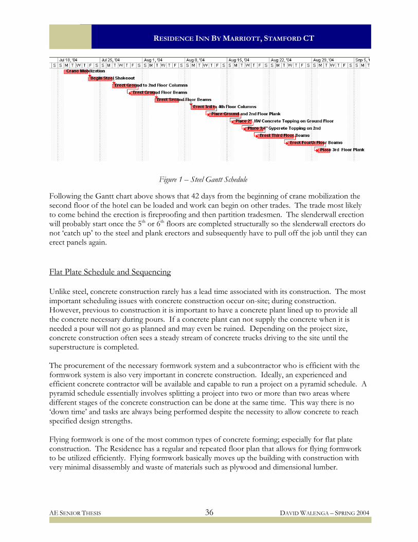
steel members are very common shapes and the precast plank is a commonly massed produced precast item. However, proper planning would still have to take place to avoid delays. Lead time issues can be prevented, but on-site coordination issues are quite different. The Residence Inn is located in the heart of the city of Stamford Connecticut. The hotel’s site is large enough to sustain construction activities but it is also small enough that the shakeout and organization of materials like steel and precast plank will have to be done with care. The ability to have enough material laid out in a organized manner on site for more than a day’s worth of work can greatly improve the overall efficiency of steel erection and precast placement. This is true for any project but more so with steel construction due to the puzzle-like construction of its system. The next scheduling issue of importance for steel construction involves the steady flow of material to the site. Once about two floors are erected the erector and project managers involved have a pretty good idea as to how long subsequent floors will take to erect and their efficiency will improve with successive floors. With an idea as to how long it takes to erect material a schedule of deliveries can be set to ensure material arrives on site when it is needed. On a project this size, daily deliveries will be required to keep up. Scheduling aside, construction sequencing is a key process in the construction of a building. Sequencing is a vital part of construction and often overlooked by those who are not on-site or not directly involved with the day-to-day assembly of a building. The basic purpose of sequencing is to have trades begin their work as soon as the trade before has completed the work necessary to allow them to begin. Relating sequencing to the construction of a building’s superstructure begs the question: when can the next trade get on the floor and start working? The answer to this question is: the next trade can begin work on a level when that level can be loaded with material and when the level above is at least closed in to prevent the fall of material onto workers. To examine this, a Gantt schedule was created in Microsoft Project to follow the construction of the steel structure to the point where the ground floor and second floor can be loaded and worked on. The results of this schedule are shown on the following page in Figure 1.
AE SENIOR THESIS 35 DAVID WALENGA – SPRING 2004
RESIDENCE INN BY MARRIOTT, STAMFORD CT
Figure 1 – Steel Gantt Schedule Following the Gantt chart above shows that 42 days from the beginning of crane mobilization the second floor of the hotel can be loaded and work can begin on other trades. The trade most likely to come behind the erection is fireproofing and then partition tradesmen. The slenderwall erection will probably start once the 5th or 6th floors are completed structurally so the slenderwall erectors do not ‘catch up’ to the steel and plank erectors and subsequently have to pull off the job until they can erect panels again. Flat Plate Schedule and Sequencing Unlike steel, concrete construction rarely has a lead time associated with its construction. The most important scheduling issues with concrete construction occur on-site; during construction. However, previous to construction it is important to have a concrete plant lined up to provide all the concrete necessary during pours. If a concrete plant can not supply the concrete when it is needed a pour will not go as planned and may even be ruined. Depending on the project size, concrete construction often sees a steady stream of concrete trucks driving to the site until the superstructure is completed. The procurement of the necessary formwork system and a subcontractor who is efficient with the formwork system is also very important in concrete construction. Ideally, an experienced and efficient concrete contractor will be available and capable to run a project on a pyramid schedule. A pyramid schedule essentially involves splitting a project into two or more than two areas where different stages of the concrete construction can be done at the same time. This way there is no ‘down time’ and tasks are always being performed despite the necessity to allow concrete to reach specified design strengths. Flying formwork is one of the most common types of concrete forming; especially for flat plate construction. The Residence has a regular and repeated floor plan that allows for flying formwork to be utilized efficiently. Flying formwork basically moves up the building with construction with very minimal disassembly and waste of materials such as plywood and dimensional lumber.
AE SENIOR THESIS 36 DAVID WALENGA – SPRING 2004

RESIDENCE INN BY MARRIOTT, STAMFORD CT
Just as was done with the steel system, a Gantt schedule was created in Microsoft Project scheduling the construction of the hotel to the point where the second floor is capable of being worked on by trades other than the structural trades. This chart is shown in Figure 2 below.
Figure 2 – Flat Plate Gantt Schedule As shown in the Gantt schedule above, the construction of the hotel’s superstructure has been divided into two zones. The average square footage per floor of the hotel is around 9,000 square feet. Dividing the slab into an East and West section allows for a constant rate of progress and eliminates any downtime caused by the need to wait for concrete to reach 75% design strength. The ground floor of western portion of the building is slab-on-grad and the eastern portion is the slab over the basement. It has been assumed that construction of the ground floor would take longer than that of successive floors to allow for the construction crews to become better organized and acclimated to the site. Once the project gets on a set schedule and rhythm, a floor can be built a week without weather related or other delays. Assuming concrete accelerators are used and that shoring does not have to remain up longer than a week, the western portion of the second floor is capable of loading 28 days after start of construction with the eastern portion ready 39 days after start.
AE SENIOR THESIS 37 DAVID WALENGA – SPRING 2004

RESIDENCE INN BY MARRIOTT, STAMFORD CT
Comparison Comparing the sequencing of the two systems based on the study performed here, the flat plate system has a clear advantage over the steel with precast plank system. With the concrete system, the western portion of the 2nd floor can be loaded a full 14 days before it can be in the steel system. The eastern portion of the floor can be loaded three days sooner with the concrete system than it can with the steel system. By completing floors faster, the concrete system does not hold up the work of other trades. Allowing other trades to begin their work, it is possible to remove the construction of the superstructure from the critical path. However, the concrete structure does not have all of the advantage. The progress of the concrete structure is more dependent on the weather than steel is. A week of cold weather is a week lost in concrete construction. Rain can also affect the progress of both systems. If it starts to rain while a steel beam is being set the crews can lower the beam and set it later. If it starts to rain while a slab is being poured, then the construction crews have a much bigger problem than lowering a piece of steel. In terms of scheduling, the concrete system also has an advantage over the steel system. Without the lead times typically associated with steel and precast concrete, the construction of concrete can begin at any time. The on-site coordination required of concrete is also less involved than steel. Concrete construction can get by on considerably smaller layout areas than steel construction and the primary flow of material to the site comes in the form of concrete trucks rather than 40’ trailers hauling steel and concrete plank. Conclusions and Recommendation Conclusions A point by point list of conclusions:
Steel construction requires more pre-construction planning and on-site coordination than concrete construction.
Concrete construction is affected by inclement weather conditions more adversely than steel
construction.
Based on the schedules created, the flat plate concrete system has a lower impact on the sequencing of non-structural building trades and therefore has lower indirect costs than the steel with precast plank system.
Recommendation
Based on the analysis performed in this section, it is concluded that in terms of scheduling and sequencing flat plate concrete has a clear advantage over steel for this project.
AE SENIOR THESIS 38 DAVID WALENGA – SPRING 2004

Residence Inn by Marriott, Stamford CT
FINAL COMMENTS

RESIDENCE INN BY MARRIOTT, STAMFORD CT
FINAL COMMENTS Structural System Recommendation
Based on the conclusions made in this report and the research performed here, it is concluded that the flat plate concrete structural system is a better design alternative than the steel system. Therefore, it is recommended that flat plate concrete be the structural system for the Residence Inn by Marriott in Stamford Connecticut.
Mechanical Redesign Recommendation
The owner of the Residence Inn has the desire to lower the first cost of the building. Presented in this report is one way to lower the first cost. However, by changing to PTAC’s the quality of the mechanical system is lowered and the architecture of the building is negatively impacting. Over the life cycle of the building PTAC’s will cost more than the original design. Therefore, it is recommended that the owner not change the mechanical system of the Residence Inn and in turn find another way to lower the first cost of the building. One place to investigate would be the redesign of the 404 space parking structure of complete removal of it.
Project Scheduling and Sequencing Recommendation
Based on the analysis performed in this report, it is concluded that in terms of scheduling and sequencing flat plate concrete has a clear advantage of steel for this project.
AE SENIOR THESIS 39 DAVID WALENGA – SPRING 2004

Residence Inn by Marriott, Stamford CT
ACKNOWLEDGEMENTS

RESIDENCE INN BY MARRIOTT, STAMFORD CT
ACKNOWLEDGEMENTS I would like to take the opportunity to thank all of those who have helped me throughout my time here at Penn State and in the Department of Architectural Engineering. First, thank you to my parents. You’ve worked just as hard as I have to get me where I am today and for that I am extremely grateful. To all my friends, you are awesome and without you the last five years would have not been fun or possible. Tim Jones, Jackson Burnham, Katie Trail, Ashley Byrne and company -- thanks. Thank you to the AE Faculty for your dedication and for pushing us to keep PSU AE the best. Special thanks to the members of the structural faculty: Dr. Boothby, Dr. Memari, Dr. Geschwindner, Dr. Hanagan, and Professor Parfitt. Thank you to Dr. Riley for construction management advice. I would also like to thank the people at Holbert Apple Associates for helping me throughout the process of this thesis, especially David Holbert, Rich Apple and Eric Ober. Also thank you for the invaluable experience of work with you in the summer of 2003. And thank you to the people at BBGM, particularly Reade Elliott, and John Lindell at F.D. Rich Company.
AE SENIOR THESIS 40 DAVID WALENGA – SPRING 2004

RESIDENCE INN BY MARRIOTT, STAMFORD CT
REFERENCES American Concrete Institute, Building Code Requirements for Structural Concrete (ACI 318- 02) and Commentary (ACI 318R-02). International Building Code, 2000 Edition (IBC-2000) Naeim, Farzad. The Seismic Design Handbook, Second Edition. Massachusetts: Kluwer Academic
Publishers, 2001. Nilson, Darwin, and Charles Dolan. Design of Concrete Structures, Thirteenth Edition. New York:
McGraw-Hill, 2004. <http://www.lodgingac.carrier.com>
AE SENIOR THESIS 41 DAVID WALENGA – SPRING 2004

Residence Inn by Marriott, Stamford CT
APPENDIX