RESEARCH STUDY ON INSTRUMENT UNIT THERMAL CONDITIONING ...
51
00- 1.491 DECEMBER 19, 1966 Y THIRD QtJARTERLY PROGRIS RIIPORT RESEARCH STUDY ON INSTRUMENT UNIT THERMAL CONDITIONING HEAT SINK CONCEPTS SEPTEMB E R I TO N O V E M B E R 30, 1966 GEORGE C. MAKSHALL SPA<:I: FLIGHT CENTER HUNTSVILLII, ALAHAMA CONTRA<:T NO. NAS8-I 1201 AIRESEARCH MANUFACTURING DIVISION Lor AlU8k4, ClMrmU \
Transcript of RESEARCH STUDY ON INSTRUMENT UNIT THERMAL CONDITIONING ...
00- 1.491 DECEMBER 19, 1966
Y
T H I R D QtJARTERLY P R O G R I S RIIPORT
RESEARCH STUDY ON INSTRUMENT UNIT THERMAL CONDITIONING HEAT SINK CONCEPTS
SEPTEMBER I TO NOVEMBER 30, 1966
GEORGE C. MAKSHALL SPA<:I: FLIGHT CENTER HUNTSVILLII, ALAHAMA
CONTRA<:T NO. NAS8-I 1201
AIRESEARCH MANUFACTURING DIVISION Lor AlU8k4, ClMrmU
\
- 1 66-1491 2
"/DECEMBER 19, 1966 /
QUARTERLY PROGRESS REPORT
-.? RESEARCH STUDY ON INSTRUMENT UNIT THERMAL CONDITIONING HEAT SINK CONCEPTS
--c
SEPTEMBER 1 TQ NOVEMBER 30, 1966 I., i i
PREPARED FOR
GEORGE C. MARSHALL SPACE FLIGHT CENTER HUNTSVILLE, ALA €3 AMA .
CONTRACT NO: NAS8-I 129 1
Prepared b y : k D. W. Graumann "
.-I
Approved b y : I . G . Austin
Asy. F. E. Carroll
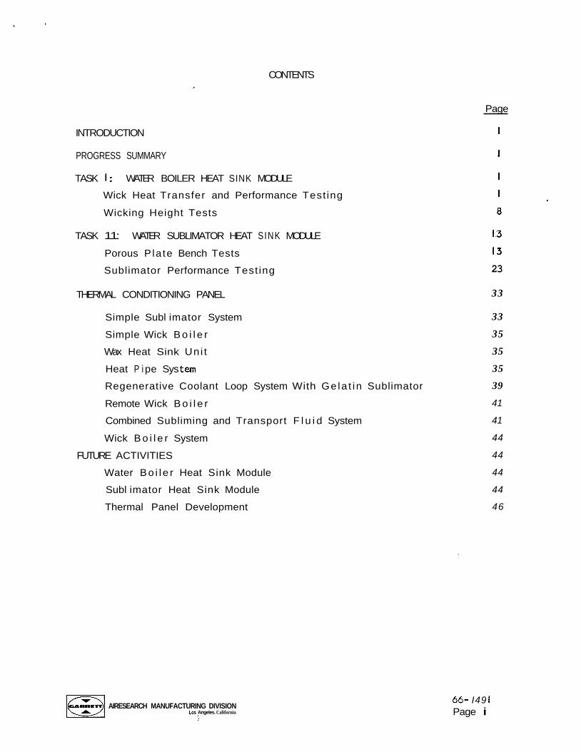
CONTENTS
INTRODUCTION
Page
i
PROGRESS SUMMARY i
TASK I : WATER BOILER HEAT SINK MODULE
Wick Heat Transfer and Performance Test ing
Wicking Height Tests
TASK 11: WATER SUBLIMATOR HEAT SINK MODULE
Porous Pla te Bench Tests
Sublimator Performance Test ing
THERMAL CONDITIONING PANEL
Simple Subl imator System
Simple Wick B o i l e r
Wax Heat Sink Uni t
Heat P i pe Sys tern
Regenerative Coolant Loop System With Ge la t in Sublimator
Remote Wick B o i l e r
Combined Subliming and Transport F l u i d System
Wick B o i l e r System
FUTURE ACTIVITIES
Water Bo i l e r Heat Sink Module
Subl imator Heat Sink Module
Thermal Panel Development
13
13
23
33
33
35
35
35
39
41
41
44
44
44
44
46
AIRESEARCH MANUFACTURING DIVISION Los Angeles. California
i
66- I49 1 Page i
F i gure
I
2
3
4
5
6
7
8
9
IO
II
12
13
14
15
16
17
18
19
20
21
22
23
24
K
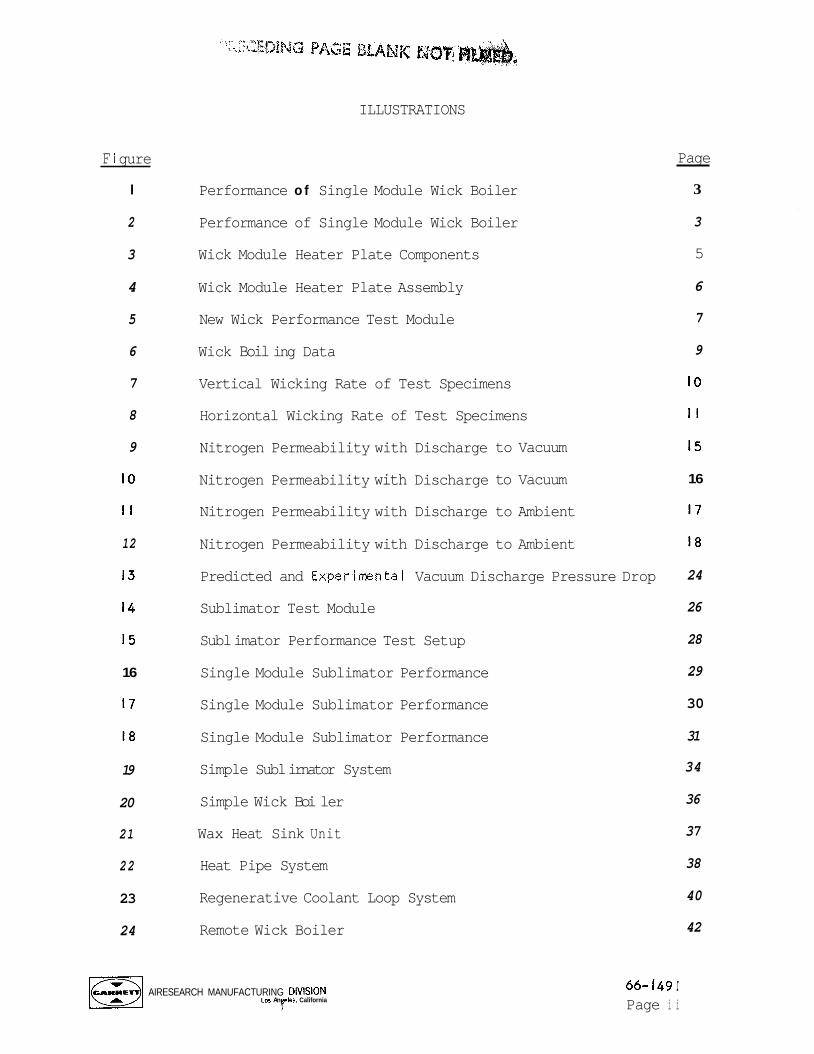
ILLUSTRATIONS
Performance o f Single Module Wick Boiler
Performance of Single Module Wick Boiler
Wick Module Heater Plate Components
Wick Module Heater Plate Assembly
New Wick Performance Test Module
Wick Boil ing Data
Vertical Wicking Rate of Test Specimens
Horizontal Wicking Rate of Test Specimens
Nitrogen Permeability with Discharge to Vacuum
Nitrogen Permeability with Discharge to Vacuum
Nitrogen Permeability with Discharge to Ambient
Nitrogen Permeability with Discharge to Ambient
Predicted and Experimntal Vacuum Discharge Pressure Drop
Sublimator Test Module
Subl imator Performance Test Setup
Single Module Sublimator Performance
Single Module Sublimator Performance
Single Module Sublimator Performance
Simple Subl irnator System
Simple Wick Boi ler
Wax Heat Sink Unit
Heat Pipe System
Regenerative Coolant Loop System
Remote Wick Boiler
Page
3
3
5
6
7
9
IO
I I
15
16
17
18
24
26
28
29
30
31
34
36
37
38
40
42
AIRESEARCH MANUFACTURING DlVlSlON Los An le. California r
66- I49 I Page i i
ILLUSTRATIONS (Continued)
Figure
25
26 Wick Boiler System
Combined Subliming and Transport Fluid System
AIRESEARCH MANUFACTURING DlVlSION Lo5 Angeles. California
1
Page
43
45
66- I49 I Page i i i
THIRD QUARTERLY PROGRESS REPORT RESEARCH STUDY ON INSTRUMENT UNIT
THERMAL CONDITIONING HEAT S I N K CONCEPTS SEPTEMBER I TO NOVEMBER 30, 1966
INTRODUCTION
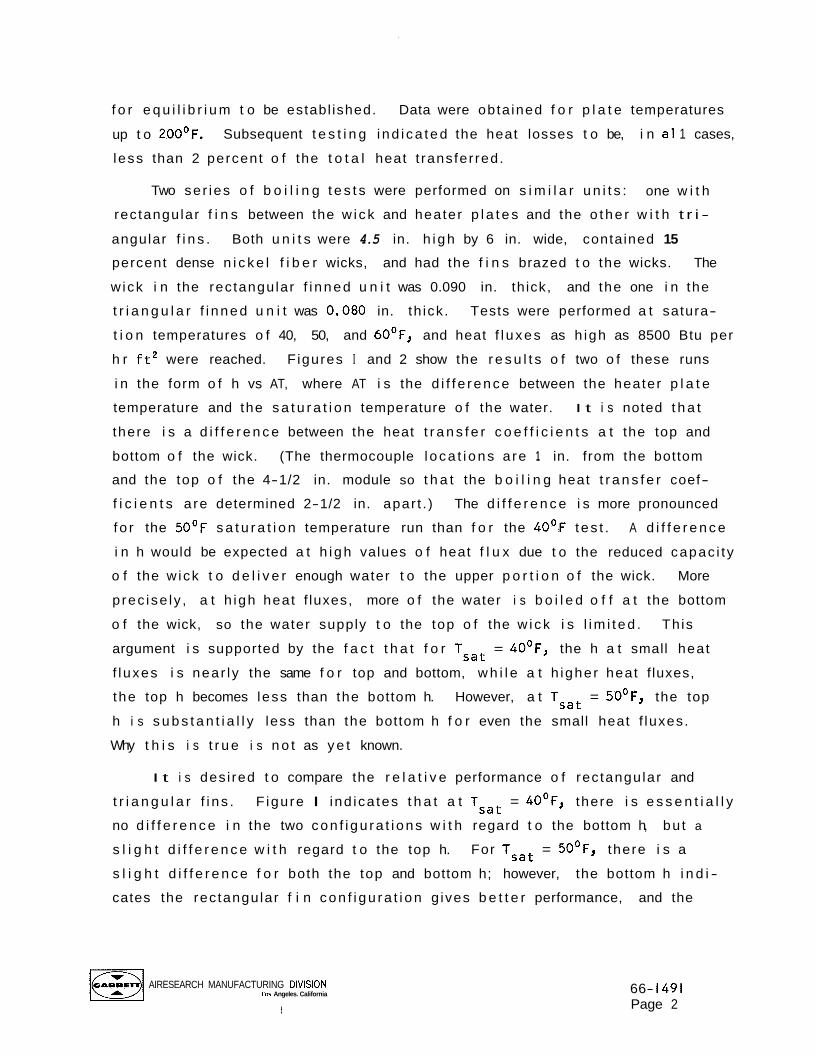
Th is repo r t reviews the work accompl ished by the AiResearch Manufactur ing
Company, a d i v i s i o n o f The G a r r e t t Corporation, Los Angeles, C a l i f o r n i a
between September I and November 30, 1966, under Nat ional Aeronaut ics and
Space Admin i s t ra t i on Contract NAS 8-11291. Th is c o n t r a c t is f o r a research
study on ins t rumenta t ion u n i t thermal c o n d i t i o n i n g heat s i n k concepts. Th is
repo r t i s the t h i r d q u a r t e r l y progress repo r t under t he referenced con t rac t
which was signed on March I I , 1966. The prev ious repo r t under t h i s con t rac t
was issued under AiResearch Report No. 66-1376.
PROGRESS SUMMARY
Dur ing the t h i r d q u a r t e r l y r e p o r t i n g period, work was accompl ished i n
the f o l lowing areas: Under Task I, Water B o i l e r Heat S ink Module, w i ck b o i l e r
modules were t es ted t o determine the r e l a t i v e performance o f rectangular and
t r i a n g u l a r f i n s . A new t e s t module was designed and fabr icated, and t e s t i n g
was continued. V e r t i c a l and h o r i z o n t a l w i ck ing r a t e t e s t s were performed.
Under Task 11, Water Subl imator Heat S ink Module, bench t e s t s were performed
on porous p l a t e s and a pressure drop c o r r e l a t i o n was developed. S ing le module
sub l imator t e s t s were conducted t o determine the performance o f var ious porous
p la tes. Under Task 111, Thermal Cond i t ion ing Panel, p r e l i m i n a r y panel designs
were conceived and i n i t i a l analyses begun.
TASK I: WATER BOILER HEAT S I N K MODULE
Wick Heat Trans fe r and Performance T e s t i n g
Upon assembly o f the s i n g l e module w i ck b o i l e r t e s t apparatus, i n i t i a l
runs were made t o c a l i b r a t e the system f o r heat leak. Th is was done by sup-
p l y i n g power t o the e l e c t r i c a l heaters w h i l e the u n i t conta ined no water.
Several runs were made fo r power l e v e l s between I and IO watts, and the system
was a1 lowed t o come t o temperature e q u i l ibrium. Temperature readings were
taken a t approximately 20-minute in te rva ls , and from 3 t o 5 hours were a l lowed
AIRESEARCH MANUFACTURING DIVISION Los An eles California 7
66- I49 I Page I
f o r e q u i l i b r i u m t o be establ ished.
up t o 20OoF.
less than 2 percent o f the t o t a l heat t ransfer red.
Data were obta ined f o r p l a t e temperatures
Subsequent t e s t i n g i nd i ca ted the heat losses t o be, i n a1 1 cases,
Two ser ies o f b o i l i n g t e s t s were performed on s i m i l a r u n i t s : one w i t h
rec tangular f i n s between the w i ck and heater p l a t e s and the o the r w i t h t r i -
angular f i n s . Both u n i t s were 4.5 in. h i gh by 6 in. wide, contained 15
percent dense n i c k e l f i b e r wicks, and had the f i n s brazed t o the wicks. The
w ick i n the rec tangular f i nned u n i t was 0.090 in. th ick, and the one i n the
t r i a n g u l a r f i nned u n i t was 0,080 in. th ick . Tests were performed a t satura-
t i o n temperatures o f 40, 50, and 6OoF, and heat f l u xes as h igh as 8500 Btu per
h r f t 2 were reached. F igures I and 2 show the r e s u l t s o f two o f these runs
i n the form o f h vs AT, where AT i s the d i f f e rence between the heater p l a t e
temperature and the s a t u r a t i o n temperature o f the water.
there i s a d i f f e r e n c e between the heat t r a n s f e r c o e f f i c i e n t s a t the top and
bottom o f the wick. (The thermocouple l oca t i ons a re 1 in. from the bottom
and the top o f the 4-1/2 in. module so t h a t the b o i l i n g heat t r a n s f e r coef-
f i c i e n t s a re determined 2-1/2 in. apar t . ) The d i f f e r e n c e i s more pronounced
f o r the 5OoF s a t u r a t i o n temperature run than f o r the 4 O o F t es t .
i n h would be expected a t h i gh values o f heat f l u x due t o the reduced capac i t y
o f the w ick t o d e l i v e r enough water t o the upper p o r t i o n o f the wick. More
p rec ise ly , a t h igh heat f luxes, more o f the water i s b o i l e d o f f a t the bottom
o f the wick, so the water supply t o the top o f the w i ck i s l im i t ed . Th is
argument i s supported by the f a c t t h a t f o r Tsat = 4OoF, the h a t small heat
f l uxes i s near l y the same f o r top and bottom, w h i l e a t h igher heat f luxes,
the top h becomes less than the bottom h. However, a t Tsat = 5OoF, the top
h i s s u b s t a n t i a l l y less than the bottom h f o r even the small heat f luxes.
Why t h i s i s t r u e i s n o t as y e t known.
I t i s noted t h a t
A d i f f e r e n c e
I t i s des i red t o compare the r e l a t i v e performance o f rec tangular and
t r i a n g u l a r f i n s .
no d i f f e r e n c e i n the two con f i gu ra t i ons w i t h regard t o the bottom h, bu t a
s l i g h t d i f f e r e n c e w i t h regard t o the top h.
s l i g h t d i f f e r e n c e f o r both the top and bottom h; however, the bottom h i n d i -
cates the rec tangular f i n con f i gu ra t i on g ives b e t t e r performance, and the
F igure I ind ica tes t h a t a t Tsat = 4OoF, there i s e s s e n t i a l l y
For Tsat = 5OoF, there i s a
AIRESEARCH MANUFACTURING DlVlSlON Las Angeles. California
1
66- I491 Page 2

300
200
h
BTWHR F T ~ OF
J 5 I O 30 50
AT, OF
Figure I . Performance o f Single Module Wick Bo i le r
300
2 00
h
BTUIHR F T ~ OF
I O 0
AT, O F A-23255
Figure 2 . Performance of Single Module Wick B o i l e r
AIRESEARCH MANUFACTURING DIVISION LasjAngeles Califorma 66- I49 I
Page 3
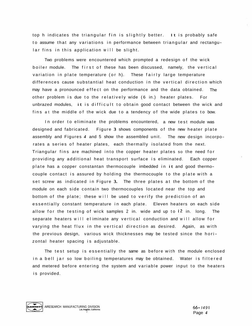
top h ind ica tes the t r i a n g u l a r f i n i s s l i g h t l y be t t e r . I t i s probably sa fe
t o assume t h a t any v a r i a t i o n s i n performance between t r i a n g u l a r and rectangu-
l a r f i n s i n t h i s a p p l i c a t i o n w i l l be s l i g h t .
Two problems were encountered which prompted a redesign o f the w ick
b o i l e r module. The f i r s t o f these has been discussed, namely, the v e r t i c a l
v a r i a t i o n i n p l a t e temperature ( o r h).
d i f f e rences cause subs tan t i a l heat conduct ion i n the v e r t i c a l d i r e c t i o n which
may have a pronounced e f f e c t on the performance and the data obtained.
o ther problem i s due t o the r e l a t i v e l y wide ( 6 in.) heater p la tes.
unbrazed modules, i t i s d i f f i c u l t t o o b t a i n good contact between the w ick and
f i n s a t the midd le o f the w ick due t o a tendency o f the wide p l a t e s t o bow.
These f a i r l y l a rge temperature
The
For
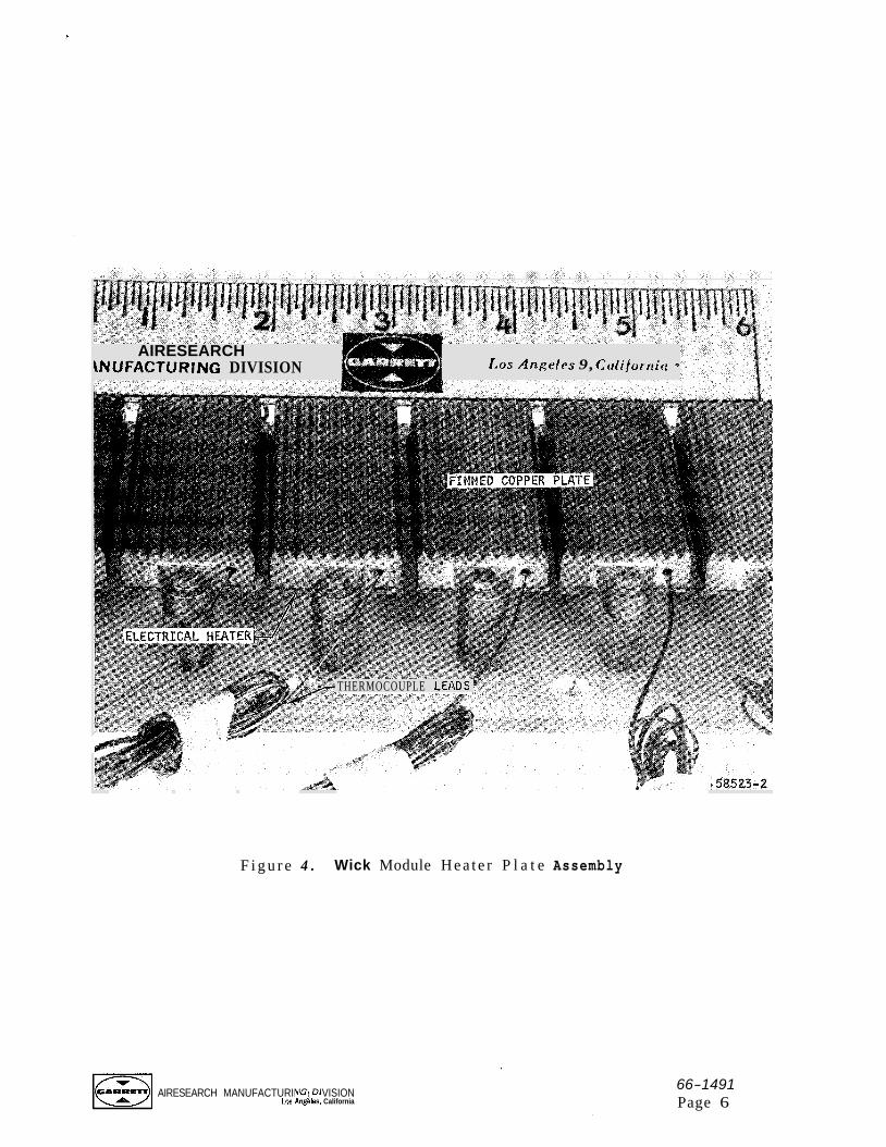
I n order t o e l im ina te the problems encountered, a new t e s t module was
designed and fabr icated.
assembly and F igures 4 and 5 show the assembled un i t .
ra tes a se r i es o f heater p lates, each the rma l l y i s o l a t e d from the next.
T r iangu la r f i n s are machined i n t o the copper heater p l a t e s so the need f o r
F igu re 3 shows components o f the new hea te r p l a t e
The new design incorpo-
p rov i d i ng any a d d i t i o n a l heat t ranspor t sur face i s e l iminated. Each copper
p l a t e has a copper constantan thermocouple imbedded i n i t and good thermo-
couple con tac t i s assured by ho ld i ng the thermocouple t o the p l a t e w i t h a
s e t screw as ind ica ted i n F igu re 3. The three p l a t e s a t the bottom o f the
module on each s i de con ta i n two thermocouples loca ted near the top and
bottom o f the p l a t e ; these w i l l be used t o v e r i f y the p r e d i c t i o n o f an
e s s e n t i a l l y constant temperature i n each p la te . Eleven heaters on each s i de
a l l ow f o r the t e s t i n g o f w ick samples 2 in. wide and up t o 12 in. long. The
separate heaters w i l l e l iminate any v e r t i c a l conduct ion and w i l l a l l ow f o r
va ry ing the heat f l u x i n the v e r t i c a l d i r e c t i o n as desired. Again, as w i t h
the prev ious design, var ious w i ck th icknesses may be tes ted s ince the h o r i -
zon ta l heater spacing i s ad jus tab le .
The t e s t setup i s e s s e n t i a l l y the same as be fo re w i t h the module enclosed
i n a b e l l j a r so low b o i l i n g temperatures may be obtained. Water i s f i l t e r e d
and metered before en te r i ng the system and v a r i a b l e power inpu t t o the heaters
i s provided.
AIRESEARCH MANUFACTURING DIVISION Los Ang les California j '
66- I49 I Page 4
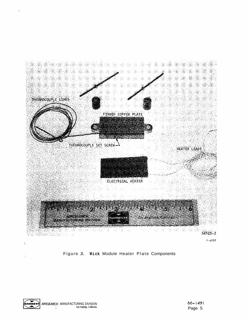
F-6292 !
F igu re 3. Wick Module Heater P l a t e Components
MANUFACTURING DIVISION Los Angelgs, California
66- ! 49 1 Page 5
Las Angcles 9, Ccriiforrtict 0
AIRESEARCH \NUFACTURING DIVISION
THERMOCOUPLE LEADS
F i g u r e 4 . Wick Module H e a t e r P l a t e Assembly
AIRESEARCH MANUFACTURING DIVISION Los An&, California
66-1491 Page 6
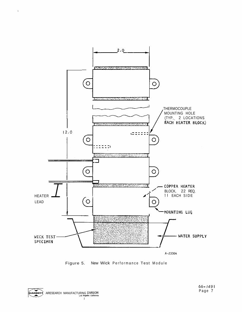
12.0
HEATER I LEAD
1 ,THERMOCOUPLE MOUNTING HOLE (TYP, 2 LOCATIONS
3
BLOCK, 22 REQ, I I EACH S I D E
\MOUNTING LUG
I
A-23304
Figure 5. New Wick P e r f o r m a n c e Tes t M o d u l e
AIRESEARCH MANUFACTURING DlVlSlON Los Angeles California
J
66- I49 I P a g e 7
The t e s t procedure invo lved s e t t i n g a given heat f l u x and sw i tch ing on
the heaters, s t a r t i n g w i t h those a t the bottom and proceeding upward.
t i o n temperature and heat f l u x were va r i ed and the hea te r temperatures were
recorded a f t e r each heater was turned on and the system had reached equi 1 ibrium.
Satura-
Tests have been completed f o r a 0.090 in. th ick , 15 percent dense n i c k e l
f i b e r metal w i ck f o r a s a t u r a t i o n temperature o f 4OoF and heat f l u x e s ranging
from 900 Btu per h r f t2 t o 9000 Btu per h r f t2. F igure 6 shows the e f f e c t i v e
h as a f u n c t i o n o f the d i f f e rence between the heater temperature and the
s a t u r a t i o n temperature f o r va r ious v e r t i c a l p o s i t i o n s on the wick. There
does not appear t o be a cons is ten t d i f fe rence between the c o e f f i c i e n t s
obta ined near the bottom and the top of the w ick f o r t h i s p a r t i c u l a r sample.
A curve which most near
20 percent above and be
these 20 percent l ines,
shape o f the curve i s s
y approximates the data i s shown as w e l l as curves
ow. As indicated, most o f the data p o i n t s l i e w i t h i n
represent ing good agreement f o r boi 1 ing data. The
m i l a r t o t h a t obta ined w i t h data from the prev ious
t e s t r i g . The e f f e c t i v e b o i l i n g c o e f f i c i e n t increases w i t h increas ing AT,
peaks a t about 15 t o 2OoF AT and then decreases.
The data ind ica tes t h a t there i s n o t a s i g n i f i c a n t change i n b o i l i n g
performance a t a c e r t a i n p o s i t i o n as a d d i t i o n a l heaters above i t a re swi tched
on.
w i l l be swi tched on simultaneously, thereby reducing the t e s t t ime
s i gn i f i cant 1 y.
Therefore, . i n f u t u r e tests, a l l the heaters which do n o t exceed 2OO0F
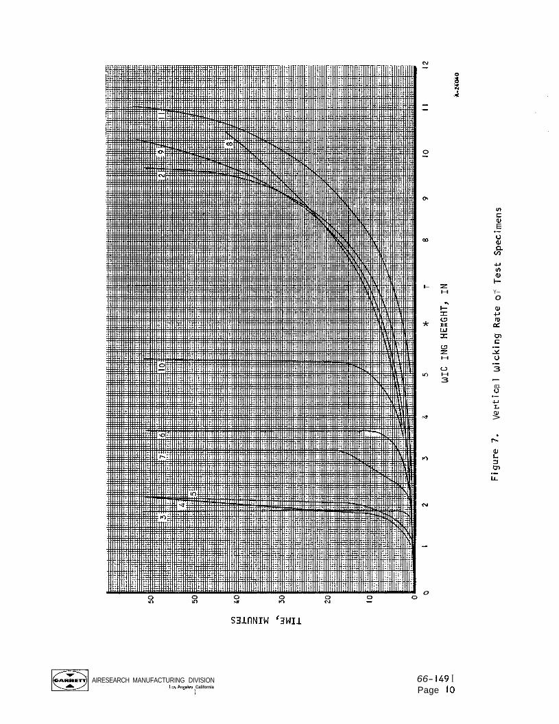
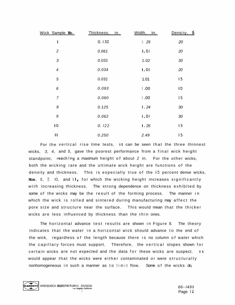
W i c k i ng Height Tests
To a i d i n s e l e c t i o n o f optimum wicks f o r the bo i l e r , v e r t i c a l r i s e t ime
and ho r i zon ta l advance t ime t e s t s were performed on the wicks 1 i s t e d on
Page 12.
The r e s u l t s of these t e s t s a re g iven i n F igures 7 and 8 where w i ck i ng
he igh t i s shown as a f unc t i on o f time, I t i s d i f f i c u l t t o o b t a i n a cons is ten t
c o r r e l a t i o n between the r e s u l t s o f these t e s t s and the w ick p rope r t i es 1 is ted.
AIRESEARCH MANUFACTURING DIVISION Los Angeles. Callforma
1
66- I49 I Page 8

Error An error occurred while processing this page. See the system log for more details.
I-
*
0
z H
c" I 0 H w r 0 2
0
H
H 3
S3lflNIW '3WIl
AIRESEARCH MANUFACTURING DIVISION Los Angeles California
1
66- I49 I Page 10
w ln QJ I- Y- O
a, w ((1 cr: (3, K .- 2i u .- 3
((1 u w L aJ >
c
.-
v) W I 0 z H
r" t; z W -I
[=I AIRESEARCH MANUFACTURING Los Angeles. DIVISION California
i
v) c a, E 1-
.v v) a, I- rc 0 a, +J
m d
m c .̂ 2f V
3 .- c m
66- I49 I Page I I
Wick Sample No.
I
2
3
4
5
6
7
8
9
I O
I
For t he
wicks, 3, 4 ,
standpoint,
Thickness, in.
0. I32
0.061
0.031
0.034
0.031
0.093
0.060
0.125
0.062
0. I 2 2
Width, in.
I . 25
I .01
1.02
I .01
1.01
I .oo
I .oo
I . 24
I .01
I . 25
Densi ty, $
20
20
30
20
15
I O
15
30
30
15
0.250 2.49 15
v e r t i c a l r i s e t ime tests, i t can be seen t h a t the three th innes t
and 5, gave the poorest performance from a f i n a l w ick he igh t
eaching a maximum he igh t o f about 2 in. For the o the r wicks,
both the w i ck i ng r a t e and the u l t i m a t e w ick he igh t are func t ions o f the
dens i t y and th ickness. This i s e s p e c i a l l y t r u e o f the 15 percent dense wicks,
Nos. 5 , 7, IO, and II, f o r which the w ick ing he igh t increases s i g n i f i c a n t l y
w i t h increas ing th ickness. The s t rong dependence on th ickness e x h i b i t e d by
some o f the wicks may be the r e s u l t o f the forming process. The manner i n
which the w i ck i s r o l l e d and s i n t e r e d dur ing manufactur ing may a f f e c t the
pore s i z e and s t r u c t u r e near the surface. Th is would mean t h a t the t h i c k e r
wicks a re less in f luenced by th ickness than the t h i n ones.
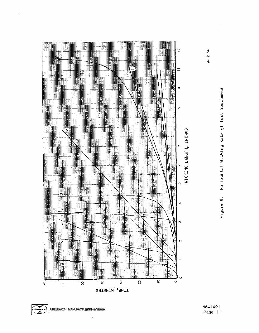
The h o r i z o n t a l advance t e s t r e s u l t s a re shown i n F igure 8. The theory
ind ica tes t h a t the water i n a h o r i z o n t a l w i ck should advance t o the end o f
the wick, regardless o f the leng th because there i s no column o f water which
the c a p i l l a r y fo rces must support. Therefore, the v e r t i c a l slopes shown f o r
c e r t a i n wicks a re no t expected and the data f o r these wicks are suspect. I t
would appear t h a t the wicks were e i t h e r contaminated o r were s t r u c t u r a l l y
nonhomogeneous i n such a manner as t o l i m i t flow. Some o f the wicks do,
AI RESEARCH MANU FACTURI NG DIVISION Los Angeles. California
I 66- I49 I Page 12

however, e x h i b i t the expected tendency and cont inued t o w i ck u n t i l e i t h e r
the top o f the w i c k was reached or the t e s t was terminated.
t h a t c e r t a i n o f these wicks d i d no t per form as expected, they a r e be ing
rec 1 eaned and r e tested.
Due t o the f ac t
TASK 11: WATER SUBLIMATOR HEAT SINK MODULE
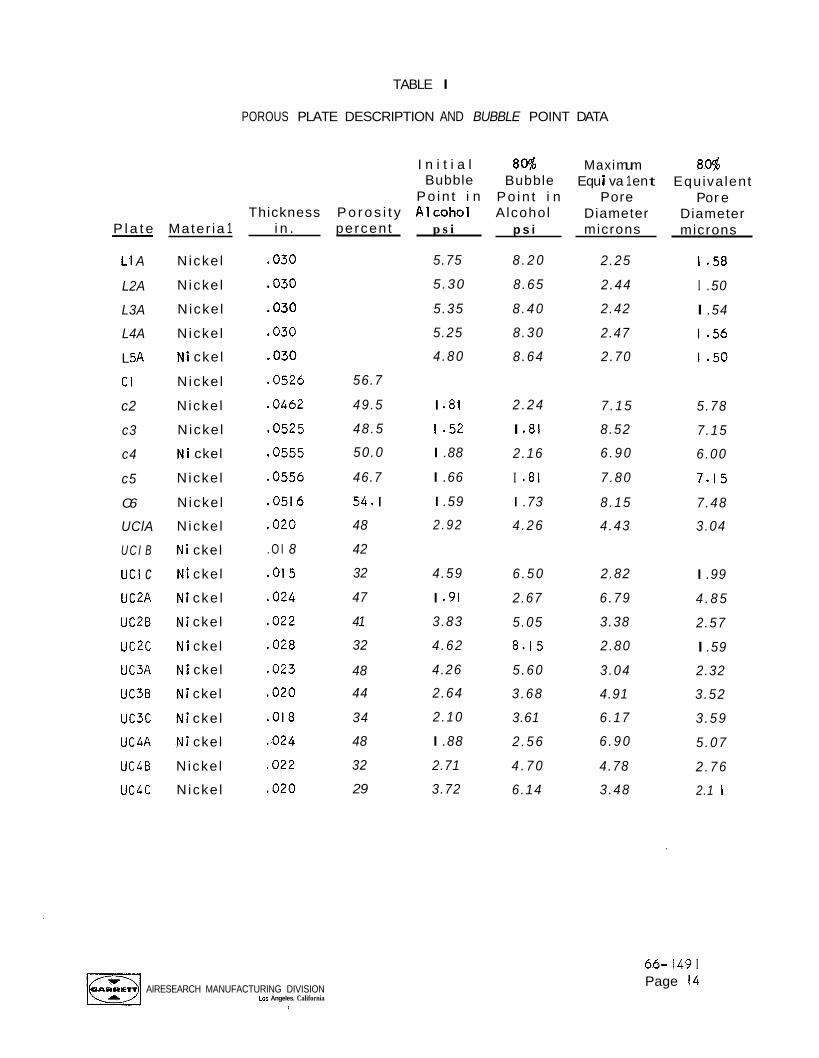
Porous P l a t e Bench Tests
A se r i es o f bench t e s t s has been performed on 23 porous p la tes . A l i s t
o f the p l a t e s t es ted i s g iven i n Table I , which inc ludes p l a t e i d e n t i f i c a t i o n ,
poros i ty , thickness, i n i t i a l and 80 percent bubble p o i n t s i n alcohol, and the
corresponding c h a r a c t e r i s t i c pore sizes. As indicated, a1 1 the p l a t e s t es ted
i n t h i s se r i es a re n icke l , ranging i n th ickness from 0.015 t o 0.056 in.
P o r o s i t i e s ranged from the smal les t o f 32 percent f o r one o f the Union Carbide
samples t o 56.7 percent f o r a C l e v i t e sample. A l l the specimens a re o f
s i n t e r e d p a r t i c l e const ruct ion, and Samples C I , C2, and C6 con ta in a 20 by 20
mesh, 0.007 in. diameter w i r e n i c k e l reinforcement screen. The lrL1l, "CI1,
and "UC" des ignat ions r e f e r to the Lockheed, Clev i te , and Union Carbide
Corporations, respect ive ly , f r o m whom t h i s se r i es o f p l a t e s was obtained.
I n i t i a l bubble p o i n t s i n a lcoho l were used t o determine the maximum equiva-
l e n t pore diameter o f each p la te . The Lockheed p l a t e s appear t o have the
smal l e s t maximum pore diameters, about 2.5 microns, w i t h approx imate ly 80
percent o f the pores l a r g e r than 1.5 microns. I t w i l l be shown below t h a t
these p l a t e s a re the l e a s t permeable o f a l l the p l a t e s tested. The C l e v i t e
p l a t e s have the l a r g e s t pores o f those t es ted i n t h i s series, f rom 6 t o 8
microns. The Union Carbide p l a t e s have more o f a spread i n maximum equiva-
l e n t pore diameter, from 2.82 t o 6.90 microns, w i t h the 80 percent pore
diameters equal t o f rom 57 t o 76 percent o f the maximum diameters.
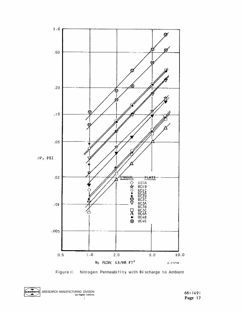
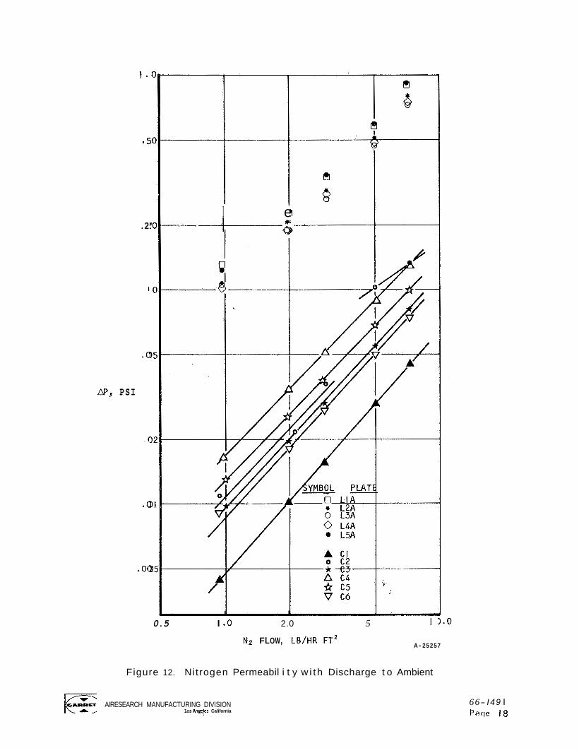
Pe rmeab i l i t y data were a l s o obta ined fo r the t h ree sets o f porous
p la tes, one s e r i e s w i t h n i t r o g e n d ischarge t o ambient, the o t h e r w i t h n i t r o -
gen discharge t o vacuum (0 .093 mm Hg abs t o 1 . 4 2 mm Hg abs). The r e s u l t s o f
these t e s t s a re shown i n F igures 9 and IO w i t h d ischarge t o vacuum, and
F igures I I and 12 w i t h d ischarge t o ambient. I t i s seen t h a t j u s t as i n
pore size, the "L" and "C" s e r i e s tend t o be bunched w h i l e the "UC" se r i es
i s spread over a range.
AIRESEARCH MANUFACTURING DIVISION Lo5 Angeles. California
I
66- I49 I Page 13
P l a t e
LI A
L2A
L3A
L4A
L 5A
C I
c2
c3
c4
c5
C6
UClA
U C I B
U C I c UC2A
U C 2 B
uc2c UC3A
UC3B
uc3c
UC4A
UC4B
uc4c
- Mater ia 1
N icke l
N icke l
N icke l
N icke l
N i cke l
N icke l
N icke l
N icke l
N i ckel
N icke l
N icke l
N icke l
N i ckel
cke l
cke l
cke l
ckel
ckel
ckel
cke l
ckel
N icke l
N icke l
TABLE I
POROUS PLATE DESCRIPTION AND BUBBLE POINT DATA
Thickness i n .
.030
.030
.030
,030
.030
.0526
.0462
.0525
.0555
.0556
.0516
.020
. O I 8
.015
.024
.022
.028
.023
,020
,018
.024
.022
.020
AIRESEARCH MANUFACTURING DIVISION Los Angeles. California
S
P o r o s i t y percent
56.7
49.5
48 .5
50.0
46.7
54. I
48
42
32
47
41
32
48
44
34
48
32
29
I n i t i a l Bubble
Po in t i n A 1 coho1
p s i
5.75
5 .30
5 .35
5.25
4 .80
I .81
1 - 5 2
I .88
I .66
I .59
2 .92
4 .59
I .91
3 .83
4 .62
4.26
2 .64
2 .10
I .88
2.71
3.72
8@!7 Bubble
Po in t i n Alcohol
p s i
8 . 2 0
8 .65
8 . 4 0
8 .30
8 .64
2 . 2 4
I .81
2 .16
I .81
I .73
4 .26
6 . 5 0
2.67
5 .05
8 .15
5 .60
3 .68
3.61
2 . 5 6
4 . 7 0
6 .14
Maxi mum Equ i va 1 en t
Pore Diameter microns
2.25
2 .44
2.42
2.47
2 .70
7 . 1 5
8 .52
6 . 9 0
7 .80
8 .15
4 .43
2.82
6 .79
3.38
2 .80
3 .04
4.91
6 .17
6 . 9 0
4.78
3 .48
80% Equivalent
Po r e Diameter microns
I .5a
I .50
I .54
1 - 5 6
1 - 5 0
5 .78
7 .15
6 .00
7.15
7 .48
3.04
I .99
4 . 8 5
2.57
I .59
2.32
3 .52
3 .59
5 .07
2 . 7 6
2.1 1
66- I49 I Page 14

2 .5
2.0
I .5
N, P S I
I .o
0.5
0
! SYMBOL PLATE
0 I A - 0 . IC * 2A 0 28 * 2c - @ 49
--
v 4c I I PLATES 38, '3C, AND L
I I I I I I I
0 I 2 3 4 5 6 7
N2 FLOW, LB/HR FT2 A-23260
Figure 9. Nitrogen Permeabi l i ty w i t h Discharge t o Vacuum
AIRESEARCH MANUFACTURING DIVISION Los Angeles. California
I 66-1491 Page 15

2.5
1.5
AP, P S I
I .o
0.5
0
I I SYMBOL PLATE
A LIA 0 L2A
Q D p - V L4A V L5A
-
0 c2 * c3 0 c4 0 c5 0 C6
/ /
---I-
I 2 3 4 5 6 7
N 2 FLOW, LB/HR FT2 A - 2 3 2 5 V
Figure I O . Nitrogen Permeabi l i ty w i t h Discharge t o Vacuum
66- I49 I Page 16
1.0
.50
.20
.IO
.05
m, PSI
.02
.01
.005
i
w- 0 U C l A * U C l B
- v UC3A UC3B uc3c
A UC4A e, UC4B 63 uc4c
0.5 I .o 2 .0 5 . 0 10.0
N2 FLOW, LB/HR FT2 A - 2 5 2 5 8
F igu re I I . Ni t rogen Permeabi 1 i t y w i t h D i scharge t o Ambient
AIRESEARCH MANUFACTURING DIVISION Los Angehs California
1 66- I49 I Page 17
1 .
. 2 '
.o
@P, PSI
.o
.oo.
I e -6 ---+---
I I
0.5 I .o 2.0 5
N~ FLOW, LBIHR F T ~
I
A- 25257
Figure 12. Nitrogen Permeabil i t y w i t h Discharge t o Ambient
AIRESEARCH MANUFACTURING DIVISION Los Angyes California
66- I 49 I P a w 18
I t i s obvious t h a t f o r a sub l imator p l a t e app l i ca t ion , a h i gh degree o f
pe rmeab i l i t y i s des i rab le . However, i t i s no t known a t t h i s t ime what i s
the s p e c i f i c pe rmeab i l i t y requirement and, therefore, i t i s no t poss ib le t o
spec i f y which ( i f any) o f the p l a t e s t es ted a re acceptable f o r t h i s app l i ca-
t ion .
such a requ i rement.
The sub l imator performance t e s t exp la ined below should a i d i n f i x i n g
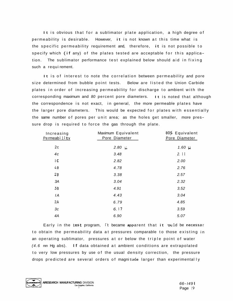
I t i s o f i n t e r e s t t o note the c o r r e l a t i o n between pe rmeab i l i t y and pore
s i z e determined from bubble p o i n t tests. Below a re l i s t e d the Union Carbide
p l a tes i n o rder o f i nc reas ing pe rmeab i l i t y f o r d ischarge t o ambient w i t h the
corresponding maximum and 80 percent pore diameters.
the correspondence i s not exact, i n general, the more permeable p l a t e s have
the l a r g e r pore diameters.
the same number o f pores per u n i t area; as the ho les get smaller, more pres-
sure drop i s requ i red t o f o r c e the gas through the p la te .
I t i s noted t h a t a l though
Th is would be expected f o r p l a t e s w i t h e s s e n t i a l l y
Inc reas ing Pe rmeab i 1 i t y
2c
4c
1c 48
28
3A
38
I A
2A
3c
4A
Maximum Equiva lent 80% Equiva lent Pore Diameter
2.80 1 ~ .
3.48
2.82
4.78
3.38
3.04
4.91
4.43
6.79
6. 17
6.90
E a r l y i n the -es t program, i t became a aren t t h a t i t
Pore Diameter
1.60 IJ.
2. I I 2.00
2.76
2.57
2.32
3.52
3.04
4.85
3.59
5.07
rou 1 d be necessa r
t o ob ta i n the pe rmeab i l i t y data a t pressures comparable t o those e x i s t i n g i n
an opera t ing subl imator, pressures a t o r below the t r i p l e p o i n t o f water
( 4 .6 mm Hg abs).
t o very low pressures by use o f the usual dens i t y cor rect ion, the pressure
drops p red i c t ed are several orders o f magni tude l a r g e r than experimental l y
I f data obta ined a t ambient cond i t i ons a re ex t rapo la ted
AIRESEARCH MANUFACTURING DIVISION Los Angeles. California i
66- I49 I Page 19
obtained values. I t i s apparent t h a t gas r a r e f a c t i o n must be considered
because o f the very low ambient pressures t o which the porous p l a t e s a re
exposed.
A t o rd i na r y pressures, gas in te rmo lecu la r d is tances are much smal ler
than the body dimensions w i t h which one i s usua l l y concerned i n f l o w ca lcu la-
t i ons and, therefore, the n o t i o n o f a continuous gas i s w e l l f u l f i l l e d . A t
low pressures, w i t h corresponding low dens i t ies , the molecular mean f r e e
path becomes comparable w i t h body dimensions, and the e f f e c t o f the molecular
s t r u c t u r e becomes a f a c t o r i n f l ow and heat t r a n s f e r mechanisms.
The r e l a t i v e importance o f e f f e c t s due t o the r a r e f a c t i o n o f a f l u i d may
be ind ica ted by a comparison o f the magnitude o f the mean f r e e molecular path
h i n the f l u i d w i t h some s i g n i f i c a n t body dimension. Hence, i f i s some
c h a r a c t e r i s t i c body dimension i n the f l o w f i e l d , the e f f e c t o f r a r e f a c t i o n
phenomena on f l o w and heat t r a n s f e r w i l l become important as soon as the
r a t i o o f h / R can no longer be neglected. Th is r a t i o i s dimensionless and i s
r e fe r red t o as the Knudsen number, Kn.
Three regimes o f f l o w o f gases may be d i s t i ngu ished: ( I ) cont i nuum flow,
i n which the gas behaves as a continuous medium; ( 2 ) s l i p flow, i n which the
mean f r e e path becomes s i g n i f i c a n t and the gas v e l o c i t y a t the w a l l i s no
longer zero; and ( 3 ) f r e e molecule flow, i n which the mean f r e e path i s so
g rea t t h a t in termolecu lar c o l l i s ions are comparat ively ra re and are, there-
fore, less important than c o l l i s i ons w i t h the wal 1. Various authors a t t ach
d i f f e r e n t values t o the Knudsen numbers which d i v i d e the f l o w regimes.
proposed f r e e molecule f l o w f o r Kn > IO, and S ta l de r2 se ts a l i m i t o f Kn > 2
w i t h s l i p f l o w e x i s t i n g a t Knudsen numbers somewhat smaller. The Knudsen
number f o r f l ow i n porous media can be expressed as
Tsien'
'Tsien, H. S., Journal o f the Aeronaut ica l Sciences, 13, 653-664, 1946
'Stalder, J. R., Goodwin, G., and Creager, M. O., "Heat Transfer t o Bodies i n a High Speed Rare f ied Gas Stream,'' NACA TN 2438, 1951
AIRESEARCH MANUFACTURING DIVISION Los Aogeles. California
1
66- I49 I Page 20
where p = v i s c o s i t y
R = gas constant
T = absolute temperature
P = pressure 1 bmf t
= conversion f a c t o r i n Newton's law o f mot ion = 32.2
= equ iva len t pore diameter
SO
De
A t the wa te r t r i p l e po in t pressure and temperature, the mean f r e e pa th f o r
water vapor i s about 7 microns and about I O microns f o r n i t r ogen gas. There-
fore, f o r the equ iva len t pore diameters c u r r e n t l y under cons idera t ion ( I t o
8 microns), the Knudsen numbers range f r o m about one t o e ight , and the re fo re
the f low i s i n the f r e e molecular and s l i p f l ow regimes.
I t i s des i rab le t o o b t a i n a c o r r e l a t i o n between pressure drop w i t h ambient
discharge and pressure drop w i t h vacuum discharge. As s ta ted above, i t i s n o t
poss ib le to c o r r e l a t e us ing dens i t y r a t i o s due t o the d i f f e r e n t f l o w regimes.
Also, i t i s n o t poss ib le t o p r e d i c t d i r e c t l y the pressure drops i n e i t h e r
regime due to u n c e r t a i n t i e s i n p l a t e cha rac te r i s t i c s , such as f r e e f l o w area
and f l o w length. However, a f a i r l y accurate c o r r e l a t i o n can be made by
w r i t i n g the pressure drop equat ions for the appropr ia te f l o w regimes and
assuming f low through constant cross- sect ion tubes.
The equat ion f o r pressure drop i n a tube i n f r e e molecular f l o w i s3 :
where C = tube per imeter
A = f r e e f l o w area
L = f l o w length
W = f l o w r a t e
3Roberts, J. K., Heat and Thermodynamics, p. 75, 1940.
AIRESEARCH MANUFACTURING DIVlSlON Los Angeles California 66-1491
Page 21

Using the d e f i n i t i o n o f the equ iva len t diameter, d = - 4A one obta ins : e C'
J" T f m L
90 e d A 'fm APfm = 1.88
The expression f o r pressure drop i n a tube i n the continuum regime i s :
w 2 4 f L C -- "c - d e 2 go Pc AZ' ( 4 )
where f = f r i c t i o n f a c t o r
Due t o the low f l ow ra tes invo lved and the l i n e a r i t y o f t e s t data, one can
reasonably assume laminar f l ow and use the expression f o r f r i c t i o n f ac to r :
C' C' u A Re W d
f = - = e
( 5 )
The value o f C' var ies w i t h the shape o f the tube cross section, and i s 16
f o r a c i r c u l a r cross sec t i on and 13.3 f o r a t r i a n g u l a r cross sect ion. Since
the porous p l a t e s a re presumably formed o f nea r l y spher i ca l p a r t i c l e s and
the f r e e f l o w area between th ree adjacent spheres i s more nea r l y a t r i a n g l e
than a c i r c l e , i t was decided t o use a value o f 13.3 i n the ana lys is . Sub-
s t i t u t i n g Equation ( 5 ) i n t o ( 4 ) and expressing p i n terms o f P, T, and R, one obta ins :
26.6 pc R Tc
AP = n wc pc go e C
D i v i d i n g Equation ( 3 ) by Equation ( 6 ) gives: - -- T f m I 'c 'fm
de w ApC C C
- 0.0707 ,/? 7 cIc ( 7 )
A s indicated, the f r e e f l ow area terms vanish, and the o n l y geometr ical term
rema i n
tes ts ,
regime
pore d
i dent i
ng i s d . Using the equ iva len t pore diameter obtained i n bubble p o i n t
f a i r l y good p r e d i c t i o n s f o r pressure drop i n the f r e e molecular f l o w
can be made us ing continuum f l o w pressure drop data. The equ iva len t
ameter obta ined i n bubble p o i n t t e s t s is, s t r i c t l y speaking, n o t
a1 t o the equ iva len t diameter term appearing i n Equation ( 7 ) ; however,
e
AIRESEARCH MANUFACTURING DIVISION 10s Angeles. California
I 66-1491 Page 22
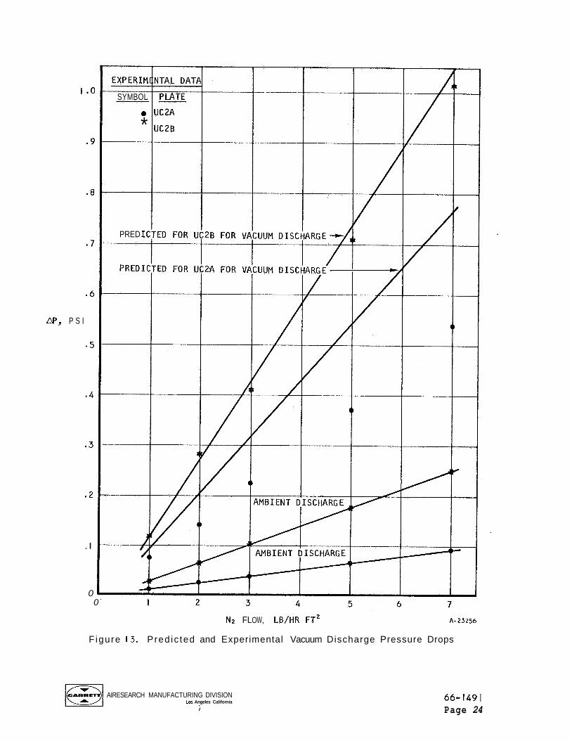
they a re thought t o be very n e a r l y equal and, s ince i t g ives good agreement
w i t h experimental data, the bubble p o i n t equ iva len t diameter was used. The
pore diameter which most c l o s e l y charac te r izes the porous p l a t e i s n e i t h e r
the maximum De no r the 80 percent De, the maximum D the 80 percent De too small. Therefore, f r e e molecular pressure drop pre-
d i c t i o n s were based upon an average o f the two D values. F igu re 13 shows
the vacuum discharge pressure drop p r e d i c t i o n s and experimental data fo r two
porous p la tes, as w e l l as the ambient discharge pressure drop experimental
values from which pressure drop p r e d i c t i o n s were made. The two p l a t e s shown
e x h i b i t the bes t and t he wors t agreement between p r e d i c t i o n s and experimental
be ing t oo l a rge and e
e
data obta ined i n these tests . Table 2 shows the r a t i o o f the experimental
vacuum discharge pressure drops t o the p red i c ted pressure drops for a l l data
p o i n t s taken i n t h i s ser ies. F i f t y - o n e percent o f t he pressure drop data
p o i n t s taken w i t h vacuum discharge were w i t h i n IO percent o f the p red i c ted
values, and 85 percent were w i t h i n 20 percent o f the p red i c t i on .
Sub1 imator Performance T e s t i n q
I n o rder t o determine the performance o f var ious porous p l a t e s i n a
subl imator, and t o c o r r e l a t e the performance w i t h bench tests, a subl imator
module t e s t apparatus was designed and assembled. The s i n g l e porous p l a t e
module i s s i m i l a r i n p r i n c i p l e t o the sub l imat ion v i s u a l i z a t i o n t e s t module
descr ibed i n prev ious repor ts i n t h a t i t cons i s t s o f a heat source, a f i nned
water passage and a porous p la te . The heat source i s an e l e c t r i c a l hea te r
so t h a t p rec i se c o n t r o l o f the i npu t heat f l u x may be maintained. The u n i t
i s instrumented w i t h 6 thermocouples i n the heater p l a t e and one a t the
water i n l e t , and cont inuous temperature readout i s provided. The porous
p l a t e module i n s t a l l e d i n the t e s t r i g i s shown i n F igu re 14. For some o f
the t h i nne r porous p l a t e specimens, i t was necessary to a t tach a d d i t i o n a l
cross bar supports to prevent the p l a t e s from bowing as shown i n the
photograph. Not shown, b u t important t o prevent hea t losses, are the l aye rs
o f a lumin ized mylar p laced on the bottom of the module next t o the heater
p la te . The th ree tubes on the l e f t s i de o f the module a re a d d i t i o n a l water
plenum i n l e t tubes which may be used i n f u tu re test ing, and the near tube
i s a water plenum pressure tap. A photograph o f the t e s t setup i s shown
AIRESEARCH MANUFACTURING DIVISION Lor Angeles California
I
66- I49 I Page 23
i .o
.9
.8
. 7
.6
N , P S I
-5
. 4
. 3
. 2
.I
0
EXPERIP
SYMBOL
0
*
PRED I(
PREDI i
0
N~ FLOW, LB/HR FT* A-25256
Figure 13. Pred ic ted and Experimental Vacuum Discharge Pressure Drops
AIRESEARCH MANUFACTURING DIVISION Los Angeles California
1 66- I49 I Page 24
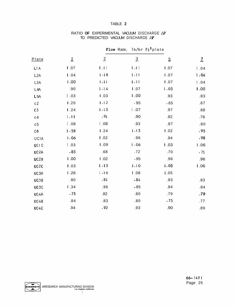
TABLE 2
P l a t e
L1 A
L 2A
L 3A
L 4A
L 5A
c 2
63
c4
c5
C6
U C l A
UCI c UC2A
UC2B
uc2c UC3A
UC3B
uc3c
UC4A
UC4B
uc4c
RATIO OF EXPERIMENTAL VACUUM DISCHARGE AP TO PREDICTED VACUUM DISCHARGE aP
Flow Rate, I b / h r f t2 p l a t e
5 - 3 - 2 - I - I .07
I .04
I .oo .90
I .03
I .20
I .24
I . I I
I .08
1 - 5 8
I .06
I .03
- 8 3
I .I I
I . I 8
I . l I
1 . I 4
I .03
I .I2
I . I 3
.91
I .08
I .24
I .02
I .09
.68
I . I I
I . I I
I . I I I .07
I .oo 95
I .07
.90
.93
I . I 3
.96
1 .06
.72
I .07
I .07
I .07
1 - 0 3
.93
65
.97
.82
.87
I .02
.94
I .03
.70
I .oo I .02 - 95 .96
I .03 1 - 1 3 I .IO I .03
I .26 I * I 6 I .08 1.05
.80 .81 .84 .83
I .34 .96 - 85 .84
.75 .82 .80 .79
.84 .83 .80 .75
.94 .92 .93 .90
AIRESEARCH MANUFACTURING DIVISION Los Angeles, California
i
7
I .04
1.04
I .04
I .oo .83
.67
.88
.78
.80
.95
.98
I .06
a 71
.96
I .06
-
.83
.84
.79
.77
.89
66- I49 I Page 25

F-629 I
Figure 14. Sublimator Test Module
AIRESEARCH MANUFACTURING D\VISION Los Angeles, California
66- I49 I Page 26
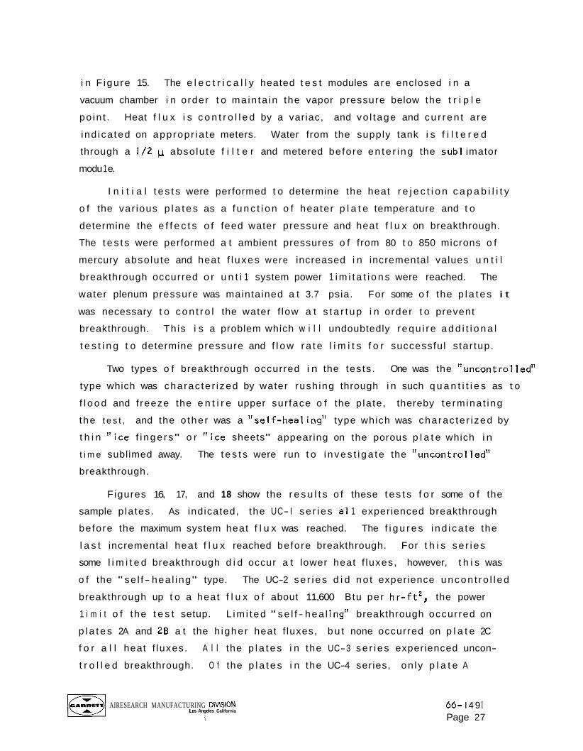
i n F igu re 15. The e l e c t r i c a l l y heated t e s t modules a re enclosed i n a
vacuum chamber i n order t o ma in ta in the vapor pressure below the t r i p l e
po in t . Heat f l u x i s c o n t r o l l e d by a variac, and vo l tage and cu r ren t a re
ind ica ted on appropr ia te meters. Water from the supply tank i s f i l t e r e d
through a 1/2 p absolu te f i l t e r and metered before en te r i ng the sub1 imator
modu 1 e.
I n i t i a l t e s t s were performed t o determine the heat r e j e c t i o n c a p a b i l i t y
o f the var ious p l a t e s as a f u n c t i o n o f heater p l a t e temperature and t o
determine the e f f e c t s o f feed water pressure and heat f l u x on breakthrough.
The t e s t s were performed a t ambient pressures o f from 80 t o 850 microns o f
mercury abso lu te and heat f l u xes were increased i n incremental values u n t i l
breakthrough occurred o r u n t i 1 system power 1 i m i t a t i o n s were reached. The
water plenum pressure was maintained a t 3.7 psia. For some o f the p l a t e s i t
was necessary t o c o n t r o l the water f low a t s t a r t u p i n order t o prevent
breakthrough. Th is i s a problem which w i l l undoubtedly r equ i r e a d d i t i o n a l
t e s t i n g t o determine pressure and f l o w r a t e l i m i t s f o r successful s tar tup.
Two types o f breakthrough occurred i n the tes ts . One was the l 'uncontrol ledt '
type which was charac te r i zed by water rush ing through i n such q u a n t i t i e s as t o
f l o o d and f reeze the e n t i r e upper sur face o f the p la te , thereby te rm ina t ing
the t e s t , and the o ther was a "se l f -hea l ing" type which was charac te r i zed by
t h i n ' ' i c e f i nge rs" o r " i c e sheets" appearing on the porous p l a t e which i n
t i m e sublimed away. The t e s t s were run t o i nves t i ga te the "uncont ro l led"
breakthrough.
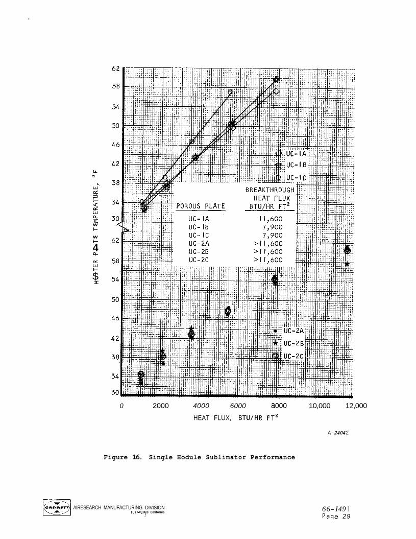
Figures 16, 17, and 18 show the r e s u l t s o f these t e s t s f o r some o f the
sample p la tes. As indicated, the UC- I se r i es a1 1 experienced breakthrough
before the maximum system heat f l u x was reached. The f i g u r e s i nd i ca te the
l a s t incremental heat f l u x reached before breakthrough. For t h i s se r i es
some l i m i t e d breakthrough d i d occur a t lower heat f luxes, however, t h i s was
o f the " se l f- hea l ing" type.
breakthrough up t o a heat f l u x o f about 11,600 Btu per h r - f t ' , the power
1 i m i t o f the t e s t setup. L im i t ed " se l f - hea l ing" breakthrough occurred on
p l a t e s 2A and 2B a t the h igher heat f luxes, b u t none occurred on p l a t e 2C
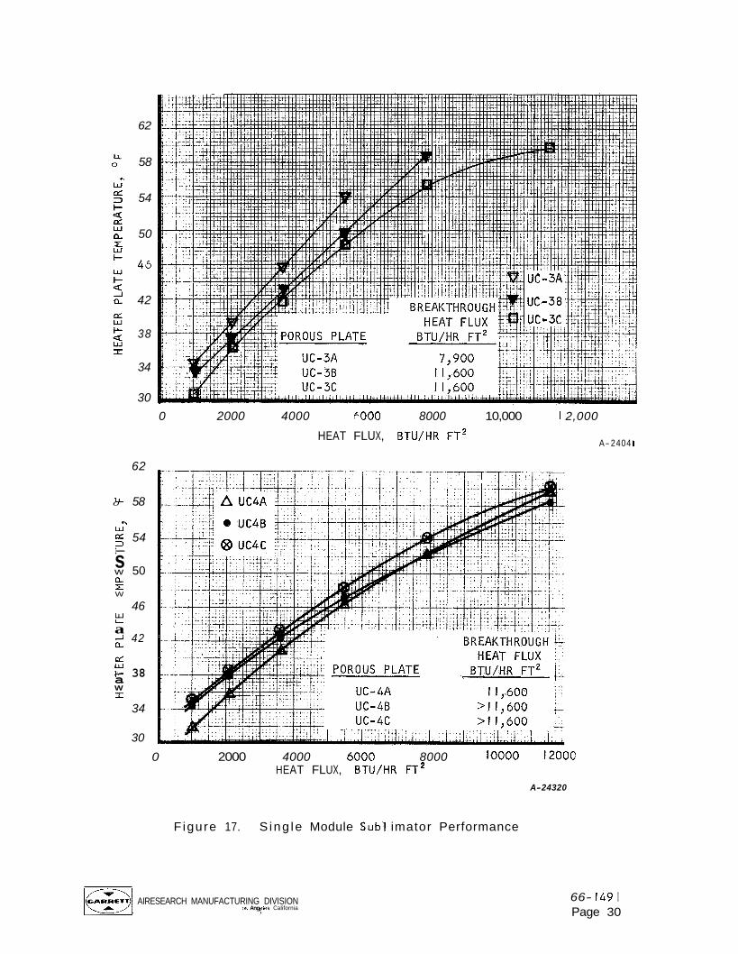
f o r a l l heat f luxes. A l l the p l a t e s i n the UC-3 se r i es experienced uncon-
t r o l l e d breakthrough. O f the p l a t e s i n the UC-4 series, on ly p l a t e A
The UC-2 se r i es d i d no t experience uncon t ro l l ed
AIRESEARCH MANUFACTURING DlVlSlON Los Angeles California
1 66- I 4 9 I Page 27

F-6137
F i gure 15. Sub1 imator Performance Test Setup
ml AIRESEARCH MANUFACTURING dlVlSION Los Angeles, California
66- I49 I Page 28
LL 0
n
I-
W I-
W + 4 n CT w I-
$ I
0 2000 4000 6000 aooo 10,000 12,000
HEAT FLUX, BTU/HR F T ~
A- 2404 2
Figure 16. Single Hodule Sublimator Performance
~1 AIRESEARCH MANUFACTURING DIVISION 10s Ange es California 5 66- I49 I
Page 29
62
58
54
50
45
42
38
34
30 0 2000 4000 6000 8000 10,000 I 2,000
HEAT FLUX, BTU/HR F T ~ A-2404 I
62
0 58 CI
W - CL 54 2 I- s w 50 a E W
46
a 2 42
tt' 38 a W I
34
30 l0000 1200c 0 2000 4000 6000 8000
HEAT FLUX, B T U / H R F T ~ A-24320
Figure 17. S ing le Module Sub1 imator Performance
16231 AIRESEARCH MANUFACTURING DIVISION Lor Ang les California f
66- 149 I Page 30
LL 0
.. W cz 3 I-
of W n x W I- w I-
a
5
Q,
Q
cz W I-
I
90
86
82
78
74
70
66
62
58
54
50
46
42
38
34
30
I 1 i 1- y;,&;.&i
1 -1 L I A
i L2A L3A 4 L4A
-- L5 A
POROUS PLATE
! I ! . I ; l . I . . I
I i i i , i d I BREAKTHROUGH
HEAT FLUX BTU/HR FT2
11,600 >I 1,600
11,600 11,600 11,600
I
HEAT FLUX, BTU/HR FT*
A-24322
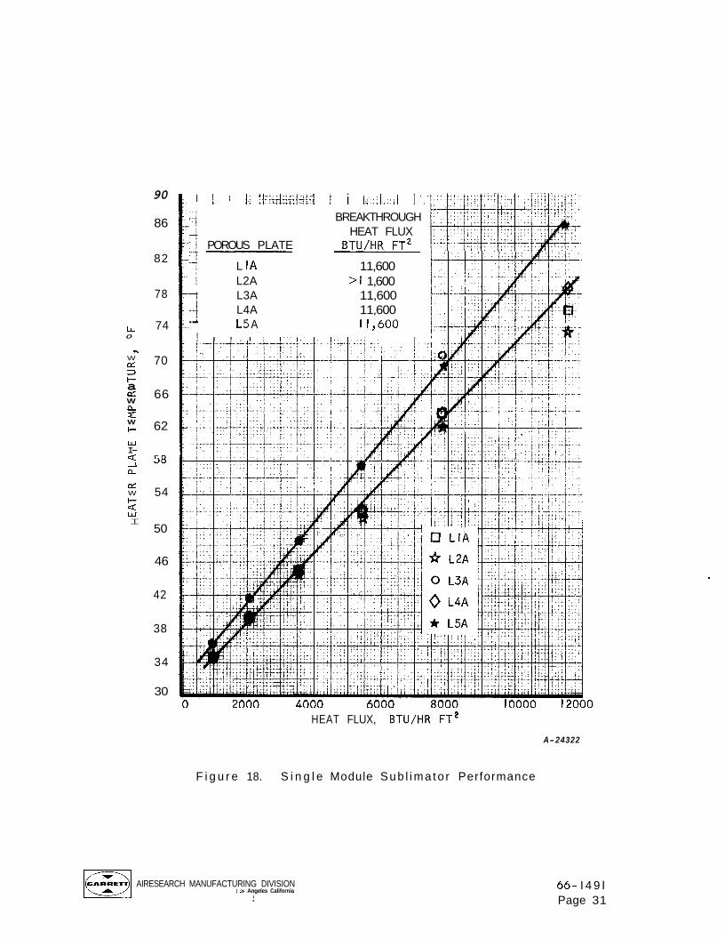
F i g u r e 18. S i n g l e Module Sub l ima to r Performance
~1 AIRESEARCH MANUFACTURING DIVISION Los Angeles California
.i 66- I 4 9 I Page 31
experienced uncon t ro l l ed breakthrough and t h i s was a t the h i g h heat f l u x . A l l
t he Lockheed p l a t e s except fo r p l a t e 2A experienced uncon t ro l l ed breakthrough.
An attempt was made t o c o r r e l a t e these breakthrough data on the bas is
o f representa t i ve pore s i z e and permeabi l i ty , and a l though t h i s has n o t as
y e t been successful on a gross basis, i t was successful w i t h i n each numbered
ser ies. The UC-2 se r i es o f p l a t e s which d i d n o t experience uncon t ro l l ed
breakthrough ranged f rom the m o s t t o the l e a s t permeable and from the l a r g e s t
t o the smal les t pore s i z e as i nd i ca ted i n Table I and F igure 9. The UC- I
s e r i e s covered a range i n pore s i z e and pe rmeab i l i t y n o t q u i t e so ex tens ive
as the UC-2 ser ies, and the p l a t e w i t h t he smal les t pores and lowest permeabi l-
i t y broke through a t t he lowest heat f l ux . I n t h e UC- 3 series, aga in the
l e a s t permeable p l a t e w i t h the smal les t pores broke through a t the lowest
heat f l u x . W i t h i n se r i es I and 3, two t rends were observed: ( I ) the l ess
permeable the plate, the h ighe r the heater temperature a t a g iven heat f l u x
and ( 2 ) the l ess permeable the p la te, the lower the hea t f l u x a t which
breakthrough occurs. These trends d i d n o t extend from one s e r i e s t o the
nex t however.
The o n l y known s i m i l a r i t y between p l a t e s i n the same se r i es i s the
s t a r t i n g powder from which the p l a t e i s s in tered. Th is appears t o be o f
some importance i n the p l a t e ' s performance; however, the complete s i g n i f i-
cance o f t h i s f a c t i s n o t understood as yet.
The exact hea te r p l a t e temperature obta ined a t the var ious heat f l u x e s
i s n o t a s i g n i f i c a n t fac to r , f o r t h i s may be v a r i e d by p l a c i n g a d i f f e r e n t
f i n i n the water passage, however the temperatures r e l a t i v e t o one another
f o r the var ious p l a t e s do g i ve some i n d i c a t i o n o f t h e i r r e l a t i v e performance.
The t e s t s shown were conducted w i t h a 0.100 in. h i g h n i c k e l f i n w i t h 2 0 f i n s
pe r inch i n the water passage. Th i s f i n and the water i n the passage composed
a s i g n i f i c a n t p o r t i o n of the hea t t r a n s f e r resistance, account ing fo r from
1 / 2 t o 3 / 4 o f the temperature drop. More s i g n i f i c a n t i n these t e s t s was the
de te rmina t ion o f the breakthrough heat f l u x e s f o r the var ious porous p la tes .
AIRESEARCH MANUFACTURING DIVISION Los A geles California P
66-1491 Page 3 2
THERMAL CONDITIONING PANEL
Conceptual design studies were initiated to develop possible thermal panel configurations. It was desired to obtain designs which meet the fol lowing system requi rements:
a. The panel should have minimal control and supporting equipment requ i remen ts.
b. The panel should be capable of handling varying heat loads as well as long quiescent periods.
c. The panel should be capable of operating independent o f the space- craft cool ing system.
Schematics of the various prel iminary concepts are shown below with brief descriptions of the operation of the units.
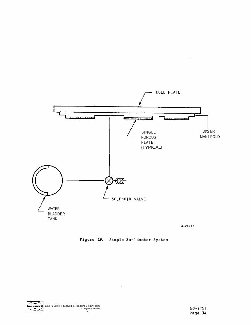
Simple Sublimator System
A simple sublimator thermal panel concept is shown in Figure 19. This design consists of a water passage between the cold plate and several porous plates with water supplied from a bladder tank. When a heat load is applied to the cold plate, a solenoid valve is opened, allowing water to flow into the water passage where it freezes and sublimes. a period o f zero heat load would be possible if after closing the solenoid valve there were an adequate amount of residual heat in the experimental equ i pmen t.
Restarting the system after
If the heat load on the cold plate were highly nonuniform, a more uniform wall temperature may be obtained by one of two ways. One method would be to include in the system a small battery operated pump which would circulate the water in the manifold, thereby evening out any wall temperature variations. The other method would be to isolate the various porous plates over the face of the cold plate, providing each with its own solenoid valve but supplied from the same water tank. water passages could provide uniform plate temperatures for nonuniform heat fluxes.
Appropriate design of the finned
~1 AIRESEARCH MANUFACTURING DIVISION Lo5 Angeles, California
I 66- I49 I Page 33
/- PLATE
L SINGLE POROUS PLATE (TYPICAL)
WAS ER MAN I FOLD
VALVE
L WATER BLADDER TANK
A-243 I 7
Figure 19. Simple Sub1 imator System
AIRESEARCH MANUFACTURING DIVISION Los Angeles California
! 66- I49 I Page 34
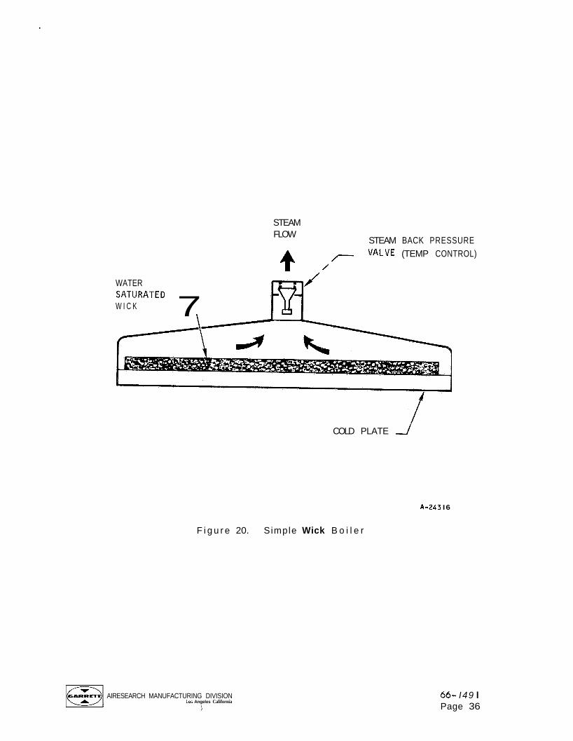
Simple Wick B o i l e r
F igu re 20 shows a conceptual design of a simple w ick bo i l e r , c o n s i s t i n g
of a wick a t tached t o t h e c o l d p late, and a steam back pressure valve. The
w ick i s i n i t i a l l y sa tura ted w i t h s u f f i c i e n t water to meet the requ i red heat
load. When t h e heat load i s appl ied, the steam back pressure va l ve i s
opened, reducing t h e plenum pressure and a l l o w i n g t h e water i n t h e w ick t o
b o i l . When the heat load i s reduced o r el iminated, t h e back pressure va l ve
i s closed, reducing o r t e rm ina t i ng b o i l i n g .
r e s t a r t e d s ince the re i s no f r e e z i n g involved. The w ick may cover the e n t i r e
c o l d p l a t e o r may be contoured t o cover o n l y the areas o f g rea tes t heat f l ux .
The steam back pressure may be c o n t r o l l e d by one o f several methods; therm-
i s t o r s may be used t o sense t h e p l a t e temperature a t var ious c r i t i c a l loca-
t ions, a Freon f i l l e d bu lb imbedded i n the c o l d p l a t e would f u n c t i o n l i k e a
t y p i c a l expansion va l ve t o c o n t r o l t h e back pressure, o r a steam temperature-
sensing Vernatherm-actuated v a l v e might be used.
The system may be e a s i l y
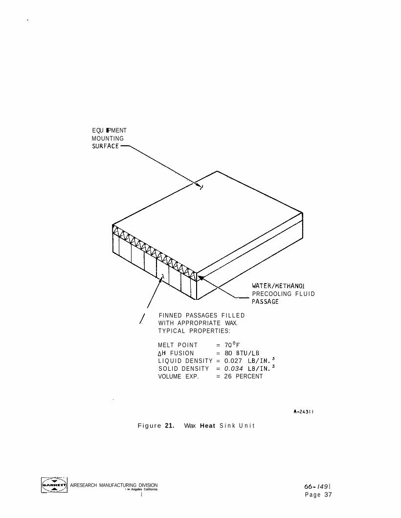
Wax Heat Sink U n i t
F i g u r e 21 i s a sketch o f a design which i s a somewhat d i f f e r e n t concept
than a sub l imator o r b o i l e r , a wax heat s i n k u n i t . Th is design, which
cons i s t s of a wax o r s i m i l a r substance w i t h a s u i t a b l e m e l t i n g p o i n t encap-
su la ted i n a f i n n e d o r honeycomb passage, i s q u i t e a t t r a c t i v e f o r small heat
loads due t o the s i m p l i c i t y o f operat ion. When t h e heat load i s app l i ed t o
the c o l d p late, t h e wax a c t s as a heat s i n k by mel t ing . No c o n t r o l s o f any
type a re needed f o r t h i s design; however, i t i s l i m i t e d t o small heat loads.
I t i s poss ib le t o o b t a i n o n l y about 80 Btu o f c o o l i n g p e r l b o f wax, whereas
w i t h a water b o i l e r o r subl imator, about 1000 Btu per l b o f water i s a v a i l -
able. The water/methanol p recoo l i ng f l u i d passage shown i n the sketch may be
connected t o the spacecraf t c o o l i n g system t o cool the equipment du r ing
launch and t o assure t h a t t h e wax i s i n a s o l i d s t a t e p r i o r t o i t s use as a
heat s i nk.
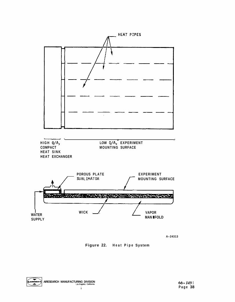
Heat Pipe System
F igure 22 i s a sketch o f a heat p i p e thermal panel system. Th is design
incorporates a w ick and vapor man i fo ld cover ing t h e c o l d p l a t e and extending
Ai RESEARCH MANUFACTURING DlVlSlON Las Angeles California
\
66- I49 I Page 35
STEAM FLOW
STEAM BACK PRESSURE
WATER
W I C K SATURATED 7
4 VALVE (TEMP CONTROL)
COLD PLATE -/
A-243 I6
F i g u r e 20. Simple Wick B o i l e r
AIRESEARCH MANUFACTURING DIVISION Los Angeles California
i
66- I49 I Page 36
E QU I PM E N T MOUNTING
PRECOOLING F L U I D
FINNED PASSAGES F I L L E D WITH APPROPRIATE WAX. T Y P I C A L PROPERTIES:
MELT P O I N T = 7OoF AH FUSION = 80 BTU/LB L I Q U I D DENSITY = 0.027 L B / I N . 3 S O L I D DENSITY = 0.034 L B / I N . 3 VOLUME EXP. = 26 PERCENT
F i g u r e 21. Wax Heat S i n k U n i t
~1 AIRESEARCH MANUFACTURING DIVISION Los Angeles California
S 66- I49 I P a g e 37
- \ t J
H I G H Q/A, LOW Q/A, EXPERIMENT COMPACT MOUNTING SURFACE HEAT S I N K HEAT EXCHANGER
POROUS P L A T E E X P E R I M E N T MOUNTING SURFACE
r I
WATER SUPPLY
WICK VAPOR MAN I FOLD
A-24313
Figure 22. H e a t P i p e System
AIRESEARCH MANUFACTURING DIVISION Lo5 Angeles California
\
66- I49 I P a g e 38
past the plate to a compact heat sink heat exchanger, in this case, a porous plate sublimator. The wick is initially saturated with water. When a heat load is applied, the water boils at the heat load and more water is transported from the cold end of the panel, that area adjacent to the sublimator. The vapor generated in boiling is condensed at the cold end so that there is a continuous circulation of liquid water through the wick and vapor through the manifold. Water from a remote supply is sublimed in the sublimator in condensing the vapor in the heat pipe. nonuniform heat fluxes may be handled sufficiently well in a heat pipe design because more water is transported to the high heat flux regions.
Just as in the simple wick design,
The controls for this system would be similar to those in a simple sublimator since no controls are needed in the wick chamber.
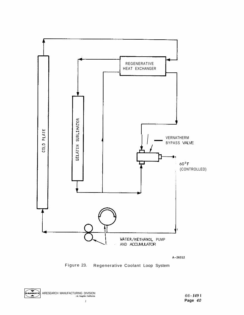
Reqenerative Coolant Loop System With Gelatin Sublimator
Figure 23 is a schematic of a regenerative coolant loop system. In this design a pump circulates the coolant (water/methanol, for instance) through the cold plate and through a sublimator where the coolant loses heat, cooling the cold plate. the heat transport fluid, all the coolant is passed through the sublimator, and temperature control is achieved by bypassing some of the fluid past the regenerator. The heat sink in this design is a sublimator, either the con- ventional water-fed type or a "gelatin subl imator." The gelatin subl imator consists o f a honeycomb passage filled with gelatin, a solid state sublimant, and a flow passage through with the water/methanol passes. The gelatin is directly exposed to space vacuum (no porous plate is used) and subl imes, just as ice does in a conventional water fed sublimator. Under these condi- tions very low equilibrium sublimation temperatures will be encountered; at low heat loads the sink temperature could be below -6OOF. The gelatin type of subliming material may be incorporated in any of the sublimator designs and is not peculiar to this particular circulating flow scheme. Since no porous plates are used with the gelatin design, the sublimator is free of any potential plugging problems. All gelatin required for a particular mission must be initially stored in the sublimator. The face of the
In order to reduce the problem of congealing or freezing of
AIRESEARCH MANUFACTURING DIVISION Los Angeles. California
I
66- I49 I Page 39
REGENERATIVE HEAT EXCHANGER
VERNATHERM I / - BYPASS VALVE
&
WATER/METHANOL PUMP AND ACCUMULATOR
60°F (CONTROLLED)
I
A-26312
F igu re 23. Regenerative Coolant Loop System
AIRESEARCH MANUFACTURING DIVISION Los Angeles California 66- I49 I
Page 40 3
sublimator is completely exposed to space; hence, the gelatin consistency must be adequate to withstand the rigors of launch. mission, a fine powder will remain in the unit which must be removed prior to reuse. For ease of operation, the sublimator can be designed to use a replaceable gelatin cartridge.
After completing a
Possible disadvantages of this system are the need for a pump to circu- late the coolant and the added weight of a regenerative heat exchanger.
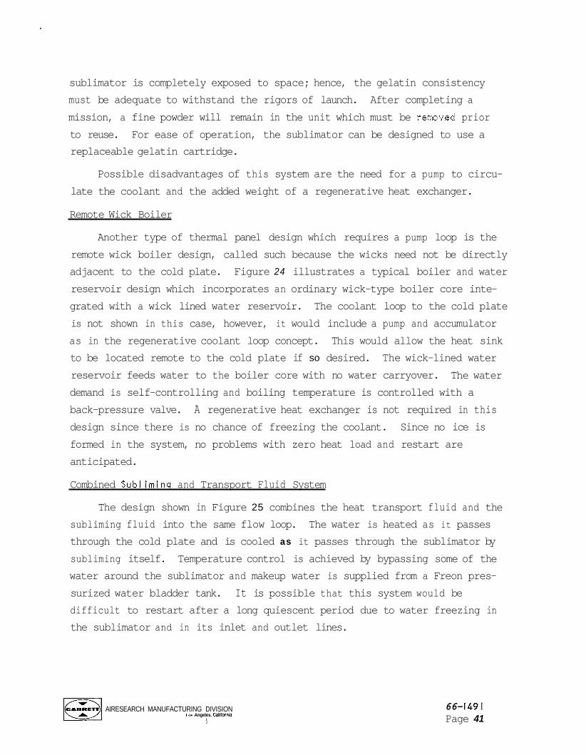
Remote Wick Boiler
Another type of thermal panel design which requires a pump loop is the remote wick boiler design, called such because the wicks need not be directly adjacent to the cold plate. Figure 24 illustrates a typical boiler and water reservoir design which incorporates an ordinary wick-type boiler core inte- grated with a wick lined water reservoir. The coolant loop to the cold plate is not shown in this case, however, it would include a pump and accumulator as in the regenerative coolant loop concept. This would allow the heat sink to be located remote to the cold plate if so desired. The wick-lined water reservoir feeds water to the boiler core with no water carryover. demand is self-controlling and boiling temperature is controlled with a back-pressure valve. A regenerative heat exchanger is not required in this design since there is no chance of freezing the coolant. Since no ice is formed in the system, no problems with zero heat load and restart are anticipated.
The water
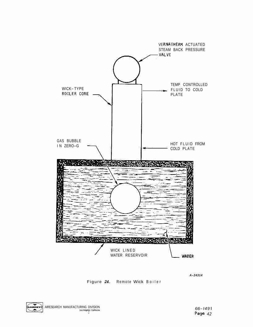
Combined Subliminq and Transport Fluid System
The design shown in Figure 25 combines the heat transport fluid and the subliming fluid into the same flow loop. The water is heated as it passes through the cold plate and is cooled as it passes through the sublimator by subliming itself. Temperature control is achieved by bypassing some of the water around the sublimator and makeup water is supplied from a Freon pres- surized water bladder tank. It is possible that this system would be difficult to restart after a long quiescent period due to water freezing in the sublimator and in its inlet and outlet lines.
AIRESEARCH MANUFACTURING DIVISION Los Angeles. Calltornla
I
66- I49 I Page 41
WICK- TYPE
GAS BUBBLE I N ZERO-G
VE RNATHERM ACTUATED STEAM BACK PRESSURE
TEMP CONTROLLED
PLATE -- F L U I D TO COLD
HOT F L U I D FROM COLD PLATE
WICK L I N E D WATER RESERVOIR i- WATER
A-24314
F igu re 24. R e m o t e Wick B o i l e r
AIRESEARCH MANUFACTURING DIVISION Los Angeles California
i 66- I49 I Page 42
COLD PLATE
BYPASS VALVE \ (TEMP CONTROL)
b
F i g u r e 25. Comb i ned
AIRESEARCH MANUFACTURING DlVlSlON LOS Angeles California
i
WATER CIRCULATING
PUMP I L
WATER BLADDER TANK
A-243 I5
Sub l im ing and T r a n s p o r t F l u i d System
SOLENOID VALVE
66- 149 I Page 43
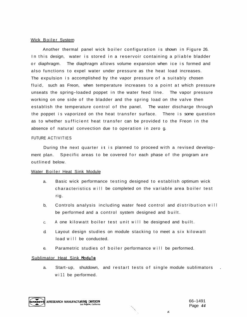
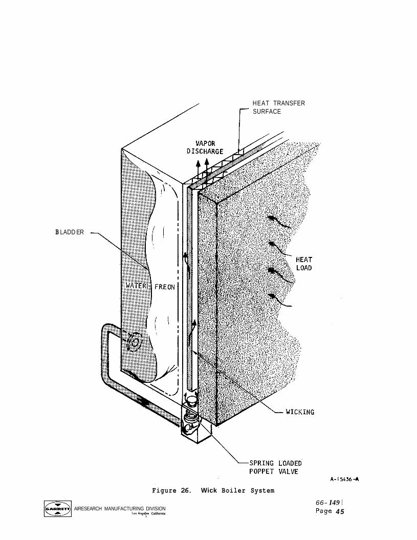
Wick B o i l e r System
Another thermal panel wick b o i l e r con f igura t ion i s shown i n F igure 26.
I n t h i s design, water i s stored i n a reservo i r conta in ing a p l i a b l e bladder
o r diaphragm. The diaphragm al lows volume expansion when i c e i s formed and
a lso funct ions t o expel water under pressure as the heat load increases.
The expulsion i s accomplished by the vapor pressure o f a su i t ab l y chosen
f l u i d , such as Freon, when temperature increases t o a po in t a t which pressure
unseats the spring- loaded poppet i n the water feed l ine . The vapor pressure
working on one s ide o f the bladder and the spr ing load on the va lve then
es tab l i sh the temperature cont ro l o f the panel.
the poppet i s vaporized on the heat t rans fe r surface. There i s some question
as t o whether s u f f i c i e n t heat t rans fe r can be provided t o the Freon i n the
absence o f natura l convection due t o operat ion i n zero g.
FUTURE ACTIVIT IES
The water discharge through
During the next quar ter i t i s planned t o proceed w i t h a revised develop-
ment plan.
ou t l i ned below.
Spec i f i c areas t o be covered f o r each phase o f the program are
Water B o i l e r Heat Sink Module
a. Basic wick performance t e s t i n g designed t o es tab l i sh optimum wick
cha rac te r i s t i cs w i l l be completed on the va r iab le area b o i l e r t e s t
r ig .
b, Controls analys is inc luding water feed cont ro l and d i s t r i b u t i o n w i l l
be performed and a cont ro l system designed and b u i l t .
C. A one k i l o w a t t b o i l e r t e s t u n i t w i l l be designed and b u i l t .
d. Layout design studies on module stacking t o meet a s i x k i l o w a t t
load w i l l be conducted.
e. Parametric studies o f b o i l e r performance w i l l be performed.
Sublimator Heat Sink Nodule
a. Start-up, shutdown, and r e s t a r t t es t s o f s i ng le module sublimators .
w i 1 1 be performed.
AI RESEARCH MANU FACTU RI Ng DIVISION Los Angehs. California
66-1491 Page 44
B LADD ER
HEAT TRANSFER SURFACE r /
Figure 26. Wick Boiler System
AIRESEARCH MANUFACTURING DIVISION Los Angeies California
3
66- I49 I Page 4 5
b. Performance tests of hydrophobic porous plates will be initiated.
c. A one kilowatt sublimator test unit will be designed and built.
d. Parametric analysis of the freezing problem and effect of steam passage dimensions wi 1 1 be performed.
Thermal Panel Development
a. Preliminary thermal panel concepts will be analyzed and revised, and one or two designs selected for development.
b. The selected concepts will be analyzed parametrically and small test units will be designed, fabricated, and tested.
AIRESEARCH MANUFACTURING DIVISION Los Angeles California
i
66- I49 I Page 46