
Informe Especial - La injusta expropiación de las acciones cochabambinas en ELFEC SA
AD-A277 072
•r.•.•,HNMT-VNTSC-FAA-94-3
of Envronn ,nt Heliport Noise Model, Nt,, D.C. 205l Version 2.2
User's Guide
Gregg G. FlemingEdward J, Rickley
U.S. Department of TransportationResearch and Special Programs AdministrationJohn A. Volpe NationalTransportation Systems CenterAcoustics FacilityCambridge, MA 02142-1093
-DTICFinal Report ELFEC-i- ,February 1994 AR ,19 4
94-08353
This document is available to the publicthrough the National Technical InformationService. Springfield, Virginia 22161
U.S. Deportment of Transportation TFederal Aviation Administration
94 3 14 0 52L. =, , i i u - i B i i

NOTICE
This document is disseminated under the sponsorship of theDepartment of Transportation in the interest of informationexchange. The United States Government assumes no liability forits contents or use thereof.
NOTICE
The United States Government does not endorse products ormanufacturers. Trade or manufacturers' names appear hereinsolely because they are considered essential to the objective of thisreport.

REPORT DOCUMENTATION PAGE FoOWB Ab. -070410188
Pbtic reporling burden for this cotlection of Information is estimated to average 1 hour per response, incLuding thetime for reviewing ingtruction.search xisnaltng data sources, gathering and maintaining the.data neeed, andIcoqmleting and reviwl n tecion of information. Send cimments regarding this burden estimte or any otheraspo~t of this coLlection 9 Informtion, including suggestions for reducing t is burden, to Washinaton He.aduarters
ervic_ Directorate for !nformation Operations and Reports, 1215 Jefferson Dyis ighway, Suite 12 0, ArLinrton VA•-•0•.and tothe 3fic f annnand -o-,,m. panrharwrk DA-1rtlon Drvi~ H(i 04•- lai. Wasnrtno r ifuh.
1. AGENCY USE ONLY (Leave blank) 2. REPORT DATE 3. REPORT TYPE AND DATES COVEREDFebruary 1994 Final Report
October 1989-February 1994
4. TITLE AND SUBTITLE 5. FUNDING NUMBERS1•M, Heliport Noise Model Version 2.2,
User's Guide FA4J7/A4035
6. AUTHOR(S)Gregg G. Fleming, Edward J. Rickley1
7. PERFORMING ORGANIZATION NAME(S) AND ADDRESS(ES) 8. PERFORMING ORGANIZATIONU.S. Department of Transportation REPORT NUMBERResearch and Special Programs AdministrationJohn A. Volpe National Transportation Systems Center DOT-VNTSC-FAA-94-3Cambridge, MA 02142
9. SPONSORING/MONITORING AGENCY NAME(S) AND ADDRESS(ES) 10. SPONSORING/MONITORINGU.S. Department of Transportation AGENCY REPORT NUMBERFederal Aviation AdministrationOffice of Environment and Energy DOT/FAA/EE/94-01800 Independence Avenue, S.W.Washington, DC 2059111. SUPPLEMENTARY NOTES Under contract to:
1 Technology & Management Systems, Inc. U.S. Department of Transportation
99 South Bedford Street, Suite 211 Research and Special Programs AdministrationBurlington, MA 01803-5128 John A. VoLpe National Transportation Systems Center
Cambridge, MA 02142-1093
12a. DISTRIBUTION/AVAILABILITY STATEMENT 12b. DISTRIBUTION CODE
This document is available to the public through the NationalTechnical Information Service, Springfield, VA 22161
13. ABSTRACT (Maximum 200 words)
The John A. Volpe National Transportation Systems Center (Volpe Center), in support ofthe Federal Aviation Administration, Office of Environment and Energy, has developedVersion 2.2 of the Heliport Noise Model (HNM). The HNM is a computer program used fordetermining the impact of helicopter noise in the vicinity of terminal operations.This document, prepared by the Volpe Center's Acoustics Facility, is a User's Guide forHNM Version 2.2. It presents: (1) computer system requirements and installationprocedures; (2) an overview of HNM capabilities and the user's implementation of thesecapabilities; (3) the elements of a heliport case study; (4) a step-by-step tutorialfor preparing and running a case study; and (5) the interpretation of HNM Version 2.2output. Also presented, in the Appendices of this document, are the following: (1) adiscussion of the technical revisions made to several internal algorithms - primarilyrevisions which are transparent to HNM users; (2) a discussion of the helicopter noiseData Base used by the HNM; and (3) a summary of error messages in the HNM.
14. SUBJECT TERKS 15. NUMBER OF PAGESHeliport Noise, Helicopters, Computer Model, Noise Contours, 94Heliport Noise Model, Noise Level Prediction, FAR Part 150,Airport Noise, Integrated Noise Model 16. PRICE CODE
17. SECURITY CLASSIFICATION 18. SECURITY CLASSIFICATION 19. SECURITY CLASSIFICATION 20. LIMITATION OF ABSTRACTOF REPORT OF THIS PAGE OF ABSTRACTUnclassified Unclassified Unclassified
ýSN 7540-01-Z80-5500 flanda~s e~r mb 9B (8 V F0 EMY 99 1 . 9)18
•1- I I I I4I8I102

PREFACE
This document was prepared by the John A. Volpe NationalTransportation Systems Center (Volpe Center), in support of theFederal Aviation Administration, Office of Environment and Energy.It is a User's Guide for the Heliport Noise Model (HNM) Version 2.2computer software used to predict noise impact around heliports.The Version 2.2 User's Guide, prepared by the Volpe Center'sAcoustics Facility, presents computer system requirements as wellas installation and operating procedures. HNM Version 2.2enhancements are also discussed.
eooession Yor O
eTIS e-iu&IDTIC TAB 13
ribistrit
Avajisbility Oodes
iDiit si

A S.U ~ ~ 1: u S:E -a2'. ~ c
"1L. Clef-
AT, 88E
0 U.U.- z o
Z C4 0 Zj
c3 C4(% O %n~ 4m tn sn
a> >J m mz LU CJ 0uJ0 V L V
jI.a a. .9
CS=0 9 5
IL I
.0 E0
E E:i E~f E. %. -% z? pzJ
k~ HorA I I 2= E a
0
z a no T. a
-0 ;. -j 'a a
SUU 4t a I , 3- P:C 0 irn. EA
0 m
CL V
LU LLiv

TABLE OF CONTENTS
ectioncie
1. INTRODUCTION .......................................... 1-1
1.1 Background ...................................... 1-11.2 HNM Capabilities ................................ 1-21.3 Computer System Requirements ................... 1-21.4 Installation .................................... 1-3
1.4.1 RAM Disk Installation ................... 1-3
1.5 Screen Displays for Use With the Keyboard ...... 1-4
1.5.1 Selection Menus ......................... 1-41.5.2 Alphanumeric Entry Menus ................ 1-5
2. ELEMENTS OF A HELIPORT CASE STUDY .................... 2-1
2.1 General Description ofHeliport Case Study Elements ................... 2-1
2.1.1 Heliport Altitude and Temperature ....... 2-12.1.2 Heliport Definition ..................... 2-12.1.3 Helicopter Definition and
the Noise Data Base ..................... 2-42.1.4 Helicopter Profiles ..................... 2-62.1.5 Takeoff Profiles ........................ 2-92.1.6 Landing Profiles ........................ 2-92.1.7 Taxi Profiles .......................... 2-132.1.8 Description of Takeoff Tracks
and Operations ......................... 2-152.1.9 Description of Landing Tracks
and Operations ......................... 2-182.1.10 Description of Taxi Tracks
and Operations ......................... 2-20
2.2 Description of "Example Heliport" ............. 2-22
3. PROGRAM START-UP AND PREPARING CASE INPUTS ........... 3-1
3.1 System Start-Up: The "HNM Main Menu" .......... 3-13.2 Case Selection .................................. 3-23.3 Edit/Load Case ................................. 3-3
3.3.1 Takeoff/Approach/Taxi Flight Menu ...... 3-11
3.4 Process Case .................................. 3-163.5 Plot Case ...................................... 3-163.6 Help .......................................... 3-16
v

TABLE OF CONTENTS (CONTINUED)
SectionPae
4. PROCESSING THE CASE .................................. 4-1
4.1 The Input File ................................... 4-14.2 Run-Time Files .................................. 4-44.3 Error Messages ................................... 4-44.4 Error Analysis and Correction ................... 4-54.5 Data Base Reports ............................... 4-54.6 Plots ............................................ 4-5
5. INTERPRETING THE OUTPUT .............................. 5-1
5.1 Echo Reports .................................... 5-15.2 Grid Analysis ................................... 5-15.3 Contour Analysis ............................... 5-13
5.3.1 Contour Analysis Report ................. 5-135.3.2 Contour Plot ............................ 5-15
6. REFERENCES ........................................... 6-1
APPENDIX A: REVISIONS TO HNM ALGORITHMS .................... A-i
A.1 Flight Significance Testing .............. A-1A.2 Dipole Directivity Pattern ............... A-iA.3 Track File (FOR13.DAT) ................... A-2A.4 References ............................... A-2
APPENDIX B: HELICOPTER NOISE DATA BASE .................... B-i
B.1 Data Base Number 2 ....................... B-2B.2 References ............................... B-2
APPENDIX C: ERROR MESSAGES AND PROBLEMS ................... C-I
C.1 Input Module Error Messages .............. C-1C.2 Flight Module Error Messages ............. C-4C.3 Computation Module Error Messages ........ C-4C.4 Report Generator Module Error Messages ... C-5C.5 Contour Module Error Messages ............ C-5C.6 Plot Module Error Messages ............... C-6
APPENDIX D: HNM REQUEST FORM .............................. D-1
vi

LIST OF FIGURES
FicrurePacre
2-1 HNM COORDINATE SYSTEM .................................. 2-3
2-2 ILLUSTRATION OF TAKEOFF AND APPROACH PROFILES .......... 2-7
2-3 ILLUSTRATION OF AN HNM AIRBORNE TAXI PROFILE ........... 2-8
2-4 HNM HELICOPTER DEPARTURE OPERATINGMODE INPUT OPTIONS .................................... 2-10
2-5 HNM HELICOPTER LANDING OPERATING
MODE INPUT OPTIONS .................................... 2-12
2-6 HNM HELICOPTER TAXI OPERATING MODE INPUT OPTIONS ...... 2-14
2-7 ILLUSTRATION OF A TAKEOFF TRACK AT"EXAMPLE HELIPORT" .................................... 2-17
2-8 ILLUSTRATION OF A LANDING TRACK AT"EXAMPLE HELIPORT" .................................... 2-19
2-9 ILLUSTRATION OF A TAXI TRACK AT"EXAMPLE HELIPORT" .................................... 2-21
2-10 "EXAMPLE HELIPORT" LAYOUT ............................. 2-23
2-11 TAKEOFF AND LANDING TRACKS AT "EXAMPLE HELIPORT" ...... 2-24
3-1 HNM MAIN MENU .......................................... 3-2
3-2 CASE FILE SELECTION MENU ............................... 3-3
3-3 DATA ENTRY MENU ........................................ 3-4
3-4 SETUP MENU ............................................. 3-4
3-5 HELIPAD DEFINITION MENU ................................ 3-6
3-6 HELICOPTER SELECTION MENU .............................. 3-6
3-7 TAKEOFF FLIGHT MENU .................................... 3-7
3-8 PROCESS MENU ........................................... 3-8
3-9 GRID DEFINITION MENU ................................... 3-8
3-10 CONTOUR DEFINITION MENU ................................ 3-9
vii

LIST OF FIGURES (CONTINUED)
Fi31ure TagN3
3-11 TAKEOFF TRACK SELECTION MENU .......I................... 3-12
3-12 TAKEOFF TRACK SEGMENT DEFINITION MENU ................. 3-12
3-13 TAKEOFF PROFILE HELEICONTE MENU.........U.............. 3-14
3-14 TAKEOFF PROFILE SELECTION MENU ........................ 3-14
3-15 TAKEOFF PROFILE DEFINITION MENU ....................... 3-15
3-16 TAKEOFF OPERATIONS DEFINITION MENU .................... 3-15
4-1 INPUT TEXT FILE FOR "EXAMPLE HELIPORT" CASE STUDY ...... 4-2
5-1 SAMPLE ECHO REPORT: SETUP ............................. 5-2
5-2 SAMPLE ECHO REPORT: HELIPADS .......................... 5-3
5-3 SAMPLE ECHO REPORT: HELICOPTERS ....................... 5-4
5-4 SAMPLE ECHO REPORT: APPROACH PROFILES .................. 5-5
5-5 SAMPLE ECHO REPORT: TAKEOFF PROFILES ................... 5-6
5-6 SAMPLE ECHO REPORT: TAKEOFF TRACKS AND OPERATIONS ..... 5-7
5-7 SAMPLE ECHO REPORT: LANDING TRACKS AND OPERATIONS ..... 5-8
5-8 SAMPLE ECHO REPORT: TAXI TRACKS AND OPERATIONS ........ 5-9
5-9 SAMPLE ECHO REPORT: PROCESS .......................... 5-10
5-10 SAMPLE STANDARD GRID ANALYSIS REPORT ................... 5-11
5-11 SAMPLE DETAILED GRID ANALYSIS REPORT ................... 5-12
5-12 SAMPLE CONTOUR ANALYSIS REPORT ........................ 5-14
5-13 SAMPLE CONTOUR PLOT ................................... 5-16
viii

LIST OF TABLES
2-1 HNM OPERATING MODE DATA FOR PROFILE AND
TRACK SEGMENTS (UNDERLINE MEANS OPERATOR INPUT) ........ 2-2
2-2 HELICOPTERS STORED IN THE HNM DATA BASE ................ 2-5
2-3 OPERATING MODES AND THRUST NAMESUSED FOR TAKEOFF PROFILES ............................. 2-11
2-4 TAKEOFF PROFILE FOR "EXAMPLE HELIPORT" ................ 2-11
2-5 OPERATING MODES AND THRUST NAMESUSED FOR LANDING PROFILES ............................. 2-13
2-6 LANDING PROFILE FOR "EXAMPLE HELIPORT" ................ 2-13
2-7 PROFILE OF TAXI FROM THE TAKEOFF/LANDINGPAD TO THE PARKING PAD FOR "EXAMPLE HELIPORT" ......... 2-15
2-8 ANNUAL AVERAGE DAILY TAKEOFF OPERATIONS AT"EXAMPLE HELIPORT" .................................... 2-18
2-9 ANNUAL AVERAGE DAILY LANDING OPERATIONS AT"EXAMPLE HELIPORT" .................................... 2-20
2-10 ANNUAL AVERAGE DAILY TAXI OPERATIONS AT"EXAMPLE HELIPORT" .................................... 2-22
B-i STATUS SUMMARY OF HELICOPTER NOISE DATA FOR DATABASE NUMBER 2 .......................................... B-3
B-2 HELICOPTER DIRECTIVITY PATTERN COEFFICIENTS ............ B-4
ix/x

1. INTRODUCTION
The Heliport Noise Model ANM) is a computer program that isintended to serve as an a•d in assessing the impact of helicopternoise in the vicinity of terminal operations. HNM Version 2.2 isbased upon Version 4 of the Federal Aviation Administration's (FAA)Integrated Noise Model (INM), a similar computer program foraEiessing the impact of fixed-wing aircraft noise"'2 . The HNMdiffers from the INM in its ability to accommodate the greatercomplexity of helicopter flight activities compared to theactivities of fixed-wing aircraft. In addition, the HNM, unlikethe INM, provides a menu-driven interactive mode for entry of allinput data. The menu-driven program facilitates the preparation ofan input data file (case study), analogous to the input file forthe INM. Although the menu-driven program displays options for usewith a digitizing graphic tablet, these capabilities have not beenthoroughly tested and are therefore disabled in HNM Version 2.2.
During October 1989, through February 1994, the John A. VolpeNational Transportation Systems Center (Volpe Center), in supportof the FAA, Office of Environment and Energy, developed Version 2.2of the HNM. Kendrick and Company of Washington, D.C., undercontract to the FAA, developed a prototype version of the HNM'smenu-driven front-end. This prototype is the foundation of thecurrent front-end in HNM Version 2.2.
A large majority of the User's Guide for the Version 2.2 computersoftware was reproduced from the HNM Version 1 User's Guide. 3
Section 1 of the HNM Version 2.2 User's Guide presents computersystem requirements and installation procedures. A brief overviewof capabilities and the user's implementation of these capabilitiesis also presented in Section 1. Section 2 describes the elementsof a heliport case study. Section 3 is a step-by-step tutorialfor preparing a case study. Section 4 describes the running of anexisting case study. Section 5 discusses the interpretation of HNMVersion 2.2 output. Appendix A describes the technical revisionsmade to several internal HNM algorithms - primarily revisions whichare transparent to users. Appendices B and C, respectively,discuss the helicopter noise Data Base, and present a summary oferror messages in the HNM.
1.1 Background
In the Aviation Noise Abatement Policy, November 18, 1976, theSecretary of Transportation and the Federal AviationAdministrator reiterated the responsibility of the FAA,established by a 1969 mandate from Congress, to reduceaircraft noise. This responsibility extends to promotingcompatible land use in areas adjacent to airports andheliports, and providing technical and financial assistance toairport proprietors undertaking comprehensive noise abatementplanning.
The HNM, like the INM, is part of the FAA's continuing effort
1-1

to provide the technical means to analyze and abate aircraftnoise. The HNM can determine both the cumulative noisemeasure for continuous contours and the cumulative noisemeasure for discrete receiver locations, required by Order1050.1C, "Policies and Procedures for ConsideringEnvironmental Impacts", December 20, 1979. It can also beused for participation in the Airport Noise CompatibilityPlanning Program under Federal Aviation Regulations (FAR) Part150. FAR Part 150 was expanded in March, 1988 to includeheliports4.
Heliport planners, helicopter operators, and local governmentsare encouraged to address the recurring problems of helicopternoise impact. The significance of these problems isunderscored by increased public awareness of aircraft/airportnoise in general, and, specifically, helicopter/heliportnoise. Technologically feasible and economically reasonablesolutions to these problems are being developed by all ofthose involved with helicopter and heliport noise issues, bothprivate and governmental. The HNM is the most sophisticatedtool available to analyze heliport noise impacts; and it ispart of FAA's ongoing commitment to help resolve aircraftnoise issues.
1.2 M4X Capabilities
The HNM is a computer program used for determining noiselevels near heliports. The computed noise levels areexpressed in terms of the Day-Night Average Sound Level,abbreviated DNL with a metric designation of L•. The Ld is"a measure of the total amount of acoustic energy received at"a given receiver location over a 24-hour period, with allnoise received between the hours of 2200 and 0700 local time"weighted" with a 10-dB penalty imposed because people aremore sensitive to noise at night.
The data outputs from the HNM may be presented in terms ofequal-level "contours" around the heliport (see Figure 5-13).Contours are presented in the form of a printout of thecontour coordinates and as a plot of the contours. The HNMalso allows for the computation of noise levels at specificreceiver locations in the heliport vicinity. The output fromthis type of computation is a printed "Grid Report" (seeFigures 5-10 and 5-11). The HNM also produces a number ofsupporting reports, e.g., "Echo Reports" (see Figures 5-1through 5-9), to aid the user in developing an accuraterepresentation of input data for the HNM. File FOR17.DAT isa user-accessible ASCII version of the Data Base. Noprovision is available for the user to add to, or modify, theexisting Data Base.
1.3 Computer System Requirements
HNM Version 2.2 operates on an IBM Personal Computer(PC)-compatible platform with the following minimum
1-2

configuration:
* IBM PC-AT or compatible, Series 286microprocessor;
* 3 MB of available hard disk space;* 540 KB of Random Access Memory (RAM) or 3 MB of
RAM, if operating the HNM from a RAM disk, asdiscussed in Section 1.4.1 below;
0 Math co-processor, Series 80287;* Microsoft-compatible Disk Operating System (MSDOS)
Version 3.3; and* EGA color monitor.
In addition, the CONFIG.SYS file on the PC slated for HNMVersion 2.2 installation must contain the following lines:BUFFERS=30; and FILES=30.
1.4 Installation
The files on the HNM Version 2.2 system diskette have beenstored in a compressed format using the PKZIP Version 1.1utility software [Copyright (c) 1990 PKWare, Inc.]. With thesource drive prompt displayed on the screen, execute theUNPACK batch file to install HNM Version 2.2 on your PC:
0 UNPACK <SOURCE DRZVI• <TARGET DRIVX>
For example, the command UNPACK A C will install, from the Adrive, HNM Version 2.2 on the C drive in a subdirectory calledHNM22. Note: The UNPACK batch file will, without prompting,overwrite the contents of subdirectory HNM22, if one exists onthe user-specified target drive.
1.4.1 RAM Disk Installation
Operation of HNM Version 2.2 on a RAM disk will improvecomputation time by an estimated 5 to 15 percent, ascompared to operating it from a hard-disk drive.RAMDRIVE.SYS, an installable device driver supplied withMicrosoft-compatible DOS, allows a user to configure partof the PC's RAM as if it were a hard disk (i.e., a RAMdisk, sometimes referred to as a virtual disk). Thefollowing is an example installation of HNM Version 2.2onto a RAM disk. The user is referred to the DOS manualand/or the manual supplied with any memory managementsoftware being used if difficulties should occur.
To install RAMDRIVE.SYS for use with HNM Version 2.2, thefollowing command line should be included in theCONFIG.SYS file:
* DZVZC=.C:\DOS\RA1DRzVI.SYS 3000/3
1-3

Upon including the above command line in the CONFIG.SYSfile, the PC must be rebooted. After rebooting, the PCwill have a 3 MB RAM drive located in extended memory.The RAM drive's logical, alphabetical drive designationwill be one letter higher than the highest currentphysical drive on the PC (e.g., if a PC has a 5 inch A-drive, a 3% inch B-drive, and a hard-disk C-drive, uponrebooting, the RAM drive will be designated the D-drive).The user may now install the HNM software on the RAMdrive by designating it as the target drive forinstallation. For example:
0 A:\UNPIACK A D
The above command will automatically install the HNM fromthe A-drive onto a subdirectory (HNM22) on the RAM drive(i.e., i- this example the D-drive). The RAM drive mustnow be logically connected to the hard drive using DOS'sJOIN command. To accomplish this, an empty subdirectory,e.g., C:\RAM, must be created on the hard drive. Fromwithin that subdirectory execute the following command:
* C:\RIX\JOXN D: C:
This will assign the RAM drive, i.e., the D-drive, tooperate within the subdirectory C:\RAM on the hard drive.
Note: It is extremely important to remember that eachtime the PC is reset or its power is turned off, theinformation stored on the RAM drive will be lost. As aresult, if the HNM is run from the RAM drive, all filesmust be copied to a physical drive, e.g., a floppy drive,prior to powering-off the PC.
1.5 Screen Displays for Use With the Keyboard
The HNM includes an interactive, menu-driven input program,with context-sensitive help, for data entry and for directprocessing operations. The menus are of two types: selectionamong choices displayed on the screen, and "fill-in-the-blank"forms for alphanumeric entry.
1.5.1 Selection Menus
Figure 3-1 shows the "HNM Main Menu" for Version 2.2. Itis an example of a selection menu. A list of choices, inthis case a list of program functions, is displayed. Theuser selects a choice by highlighting the desiredfunction and selecting ENTER.
1-4

1.5.2 Alphanumeric Entry Menus
Figure 3-4 is an example of a "fill-in-the-blank" menufor the entry of alphanumeric data. A full-screenediting capability is provided. The user can move withina field with the up/down and left/right arrow keys.Many of the alphanumeric data entry screens provided bythe HNM are similar to each other. In situations wherethis similarity could result in confusion, the functionof the current menu is defined by a title in the topcenter of the display. The menu titles are referred tothroughout the User's Guide.
1-5/1-6

2. ELEMENTS OF A HELIPORT CASE STUDY
HNM Version 2.2 requires that user input data be entered via themenu-driven, interactive, graphical user interface, or using acommercially available text editor, as with the INM. This sectiondescribes the data required to produce an example case study.These requirements are illustrated by data for a specific casecalled "Example Heliport". "Example Heliport" is the case studyprovided with the HNM Version 2.2 distribution diskette. It issynonymous with the TESTCASE.INP file (see Figure 4-1).
2.1 General Description of Heliport Case Study Elements
In order to run the HNM, the user is required to provide datadescribing the heliport and its associated activity. Thesedata are described in the following sub-sections:
2.1.1 Heliport Altitude and Temperature2.1.2 Heliport Definition2.1.3 Helicopter Definition and the Noise Data Base2.1.4 Helicopter Profiles2.1.5 Takeoff Profiles2.1.6 Landing Profiles2.1.7 Taxi Profiles2.1.8 Description of Takeoff Tracks and Operations2.1.9 Description of Landing Tracks and Operations2.1.10 Description of Taxi Tracks and Operations
The minimum data required for a specific case study includethe heliport altitude, temperature and definition; and thespecification of at least one helicopter, including adescription of its profile(s), track(s), and associated numberof operations. Table 2-1 presents the operating modes forprofile and track segments.
2.1.1 Heliport Altitude and Temperature
The altitude and temperature data consist of the heliportaltitude Above Mean Sea Level (MSL) in feet (ft), and theaverage daily heliport temperature for the period underconsideration. If the scenario reflects a typical hotday, then the average summer temperature should beentered. However, most scenarios will require theaverage annual temperature. The temperature units may beeither Fahrenheit (F), Celsius (C), or Rankine (R) asspecified by the user. As with INM, temperature andaltitude are used to compute an atmospheric acousticimpedance correction.
2.1.2 Heliport Definition
The definition of the helipads and the boundaries of theheliport establish the heliport geometry and its
2-1

TABLE 2-1: HNK OPERATING NODE DATA FOR PROFILE AND TRACKSEGMENTS (UNDERLINE MEANS OPERATOR INPUT)
O1ERATIMGE MOSJOSDAATAKUT ADDITIONAL DATA (6)
DIST.DH IO THRUST ENING LOCATIONS NEADING (EXEIZ. =Efl unit.PRON M ALT PM MANS a . Y ACCUL. (EGN T2AXSI-SART BE. Axi. AS-kt OR (AXS (A) KIss) TION_______________L. UIE DURATION SAI PRTOS()-(ft) I it) (SEC) (tt) (tt) (D§G) (g)
(notes) U.) (2) (2,)) (2,4) ((1. S) i S)
STATIC OplZRTI01WS (S)
GROUD IDL 0 or 0 m GIDL X 0 0 VAC•T(lr W P)
PLIGHT IDLE Crr 0 UR FIDLI.E DEW.P 05. R m. 0 0 NA
log - ROVER CTr ALT Ri RGs D01.1P DS.P. 0 0 OR
.C)or VASe DP DSP.P 0
OGE - ROVER err ALT MU NONE 3.I. DRY.P . 0 0 NA
NOVI= WITH CONSTANT VELOCITY (MC)
TAXI err PRIOR VE IE x CiT 0 0 r 0-ALT (XO~rDup) Vt & ta
CLIMNWU 0 vy err AL Vy 7O CrPT CViT e, o OW NA(7) (7)
CRUISE 0 Vc CIT ALT 3LC 1.1 AARIV- ARRIV- CIT 0 0 PRm VyCIT CIT to Vc
DISCIWT Va CIT ALT Va APPR X CIT 0 OVA T7 VA1- FROM Vc
MOVING WITH ACCELERATION (NA)
ACCZLERATION HORIZONTAL CIT PRIOR VEX ACLU X oa Y or CPT CJT or A 0ACCRELEATE to Vy ALT (Vyfir.) &r ePT (.19 DR)
ACCELERATION CLIMB CIrT ALT or VEI. ACLC X or CIT * GAC NAto Vy L vy'[.) ePT tIT or CIT
DECELERATION DESCUIT CIT ALT 0 DCLD I CIT * NAto 0 or CIFT
IQD HORIZONTAL CIT PRIOR 0 DCLR I CIT " 0 NADECELERATI to 0 ALT
notes;(1) CrI means Calculated Fms Track.(2) Initial values at beginning of segment are ending values of prior segment.(3) DEF mans Default. and LAS-kt means Indicated Air Speed in Knots.(4) DEP.P means Default is Prior Definition.(5) Cm?? means Calculated Prom Profile and Track.(6) NA eans Not Applicable.(7) NMm will e-tend last cruise segment 2 nautical miles beyond its starting point unless otherwise defined for departure*, and
similarly beyond ending point for arrivals.(B) AldditioaL data that mst be considered in defining an appropriate profile-track model for any epecifit case.
relationship to the surrounding area. First, the usermust define a cartesian coordinate system with which todescribe the heliport. The units for distance can bespecified in feet (ft), meters (m), or internationalnautical miles (nm), i.e., 6,076.12 ft. The positive Xand Y-axes must run true west-to-east and true south-to-north, respectively, as on a typical map. The placementof the origin point (0,0) is arbitrary.
After selection of the origin, the user may employ simpletrigonometric techniques or a graph paper overlay todetermine the X- and Y-values of the helipads and thepoints on the heliport boundary. Figure 2-1 presents thecoordinate system with the positive Y-axis pointing
2-2

TRUE NORTH+y
TOUCHDOWN
-, AD
-X ,.+X
(0-0)
-y
FIGURE 2-1: BNM COORDINATE SYSTEM
2-3

towards true north. Any X-coordinate of a point to thewest of the origin and any Y-coordinate to the south ofthe origin must be a negative number.
In addition, although the user has the selectability tocharacterize the terrain over which sound propagates aseither hard or soft, the HNM Data Base currently containsdata for propagation over soft terrain only.Consequently, hard is not a valid selection and the userwill be notified as such. Examples of soft surfacesinclude grass-covered terrain and wooded areas.
2.1.3 Helicopter Definition and the Noise Data Base
At least one helicopter type must be selected from theHNM Data Base for each case study. Along with eachhelicopter type, a nominal value for its main rotor RPMis presented in the Data Base. This value may be changedby the user, as appropriate. Table 2-2 is a summary ofthe helicopters in the HNM Version 2.2 Data Base. Thetable also gives the maximum weight of each helicopter.A helicopter is selected by its name as listed in thistable or from the "Helicopter Selection Menu" of theinteractive data-entry program (see Section 3.3).
The HNM Data Base contains noise data sets for sevenoperating modes: four for essentially stationaryoperations and three for moving operations. The noisedata for the four stationary modes are as follows:
GIDLE - Ground IdleFIDLE - Flight Idle (also used for ground wheeled
taxi)HIGE - Hover in Ground Effect (also used for
airborne taxi)HOGE - Hover Out of Ground Effect
The noise data for the stationary modes consist of tablesof A-weighted Sound Exposure Levels (SEL) at eightdistances ranging from 200 to 10,00i ft. Staticdirectivity is accounted for by a set of coefficientswhich were derived from measured data.
The noise data for the three moving operations are asfollows:
TO - TakeoffAPPR - Approach for LandingLFLO - Level Flyover
The noise data for the moving modes consist of tables ofA-weighted Sound Exposure Levels (SEL) at eight distancesranging from 200 to 10,000 ft. To account for in-flightdirectionality, three sets of SEL data at each of theabove eight distances are included (i.e., left, center,
2-4

TABLE 2-2: HELICOPTERS STORED IN THE HNM DATA BASE
MaximumStorage Name Description Weight(lbs.)
1 B212 Bell 212 (UH-1N) 10,500
2 $61 Sikorsky S-61 (CH-3A) 19,000
3* S64 Sikorsky S-64 (CH-54B) 42,000
4 CH47D Boeing Vertol 234 (CH-47D) 48,500
5 H500D Hughes 500D 2,550
6 B0105 Boelkow BO-105 5,070
7* B47G Bell 47G 2,950
8 SA330J Aerospatiale SA-330J 15,432
9 B206L Bell 206L 4,000
10 A109 Augusta A-109 5,730
11 SA341G Aerospatiale SA-341G 3,970
12* H300C Hughes 300C 1,900
13 S65 Sikorsky S-65 (CH-53) 37,000
14 S70 Sikorsky S-70 (UH-60A) 20,250
15 S76 Sikorsky S-76 10,000
16 SA365N Aerospatiale SA-365N 8,488
17 SA355F Aerospatiale SA-355F 5,070
18 SA350D Aerospatiale SA-350D 4,300
19 B222 Bell 222 7,800
20** R22HP Robinson R22HP 1,300
21** BK117 Boelkow BK-117 6,283
* Indicates no data in Data Base.
* Indicates directivity data only in Data Base.
2-5

and right). The left and right data are corrected toelevation angles of 45 degrees. The center data are foran elevation angle of 90 degrees.
For level flyovers, the data are given for a singletypical speed. Values of SEL at other speeds arecomputed in the HNM using constants stored in the firstthree positions of the LFLO data table.
Appendix B contains a complete description of the HNMVersion 2.2 Data Base. Note that the HNM, unlike theINM, does not provide for insertion of alternative noisedata.
2.1.4 Helicopter Profiles
The three types of profiles used in the HNM are asfollows:
"* Takeoff Profiles"* Landing Profiles"* Taxi Profiles
For examples of these profiles see Figures 2-2 and 2-3.
Since there are many ways to operate a helicopter, it isnot feasible to incorporate a number of standard profilesin the HNM . Rather, it is necessary that the HNM useprofiles appropriate to each specific helicopter type asit operates at a heliport. Since entry of profile datais a regular requirement in the use of the HNM, themenu-driven screens significantly assist the user.For each segment of a helicopter profile, the user will
be required to provide the following four items:
0 Operating mode (thrust name).
0 Ground distance of the point from start of theoperation in user specified units (ft, m or nm).
* Altitude in ft above the heliport.
0 The velocity in knots (kt) at the point or, forstatic operations, duration in seconds of theoperation at the point.
Each profile must contain at least three segments, but nomore than fourteen.
2-6

0 A.
z cc
*e a
all
U';
wti a i
0 J
F~I oW
21-7

A) INITIAL PHASE (TAKEOFF PORTION)
TAXI AT CONSTANT VELOCITY
VERTICALASCENTI
E N IGROUNDSTART GROUND IDLE
0 VERTICAL ASCENT
SINITIAL GROUND TAXI MOTION
8) TERMINATION PHASE (LANDING PORTION)
Q TAXI AT CONSTANT VELOCITY
VERTICALI DESCENT
GROUND --'1•,
O GROUND IDLE
@STOP
FIGURE 2-3: ILLUSTRATION OF AN I[NM AIRBORNE TAXI PROFILE
2-8

2.1.5 Takeoff Profiles
Figure 2-4 is a flow chart which can accommodate theelements of several possible takeoff procedures.Specific procedures may skip some of these elements oradd additional elements, as appropriate.
There are a total of 13 helicopter operating modesavailable in the HNM. Of these, nine modes may beappropriate for use in takeoff profiles (See Table 2-3).Table 2-4 contains a takeoff profile for "ExampleHeliport". It contains nine profile points which defineeight profile segments and five operating modes, i.e.,thrusts. At the last point, Point 9 in Table 2-4, novalue of thrust is necessary.
For static operations not involving horizontal movement,the duration entered at a point is the duration of theoperation initiated at the point. For example, for Point1 at a distance of zero ft, thirty seconds is theduration of the operation at HIGE thrust. For Point 6 ata distance of 562 ft from the helipad and an altitude of30 ft, the velocity is 60 kt, and it resulted from theacceleration of the previous segment.
2.1.6 Landing Profiles
Figure 2-5 is a flow chart which can accommodate theelements of several possible landing procedures.Specific procedures may skip some of these elements oradd additional elements, as appropriate.
Of the 13 helicopter operating modes identified in theHNM, eight modes may be appropriate for use in landingprofiles (see Table 2-5). Table 2-6 contains a landingprofile for "Example Heliport". It contains sevenprofile points which define six segments. At the lastpoint, Point 7 in Table 2-6, no value of thrust isnecessary.
For static operations not involving horizontal movement,the duration entered at a point is the duration of theoperation initiated at the point. For example, for Point5 at a distance of zero ft and an altitude of three ft,three seconds is the duration of the operation at HIGEthrust. For Point 3 at a distance of 4,819 ft from thelanding helipad and an altitude of 1,000 ft, 60 kt is thevelocity, resulting from the deceleration of the previoussegment.
2-9

START > RUDIL
FIG..v-IDLEION.- VERTICALASCENT AND
HOVER
DIEC 1)DRC CIB 2 VRIA ACN ) OIOTA C
2OE - HOVLSER
OONE - HORIZOTAL
ACCELERATION
TO CRUISEACEEI
FIGURE 2-4: HNM HELICOPTER DEPARTURE OPERATING MODE INPUT OPTIONS
2-10

TABLE 2-3: OPERATING MODES AND THRUST NAMES USEDFOR TAKEOFF PROFILES
Thrust Default Thrust Name
Operating Mode Name in the Data Base
Ground Idle GIDLE GIDLE
Flight Idle FIDLE FIDLE
Hover In Ground Effect HIGE HIGE
Hover Out of Ground Effect HOGE HOGE
Vertical Ascent VASC* HIGE/HOGE**
Takeoff at Constant TO TOVelocity (Vy)
Accelerating Horizontal ACLH* TOTakeoff
Accelerating Climbing ACLC* TOTakeoff
Level Flyover (Cruise) LFLO LFLO
Notes:
S The Data lam n designed to provide offset constants to add to the default noim curve.in the Data lame, these comnants are zero util erientally determined.
It the final altitude is greater thnl 1.5 tiesm the rotor diamter, HOO in used by the 100.Otherwise. f1 1t used.
TABLE 2-4: TAKEOFF PROFILE FOR "EXAMPLE HELIPORT"
VelocityDescription' Distance Altitude Duration or
(ft) (ft) IAS(kt) or SEC Thrust
1. Startup and Idle 0 0 30 (SEC) HIGE
2. Flight Idle Checks 0 0 30 (SEC) HIGE
3. Vertical Ascent to 0 0 3 (SEC) VASC15 ft. and Hover
4. Horizontal Accel. 0 15 16 (kt) ACLHto 30 kt (0.2g)
5. Climb and Accel. 100 15 30 (kt) ACLHto 60 kt at 30 ft.
6. Climb at 1,700 562 30 60 (kt) TOft./min.
7. Accel. to Cruise 4,032 1,000 60 (kt) TO
8. Begin Cruise 6,786 1,000 100 (kt) LFLO
9. End of Cruise 99,999 1,000 100 (kt)
2-11

TOAPPROACH I
1) DECELERATING NSTANT VELOCITY
- CONSTANT
VVELOCITY
DESCENT'
DECELERATION V
* MAY HAVE MORE THAN ONE SEGMENT
FIGUE� 2-5: ENM B COPTER LAING OPETING MODE INPTfl OPTIONS
2-12
I~~ Mimiiiinnm inii li ,

TABLE 2-5: OPERATING MODES AND THRUST NAMES USEDFOR LANDING PROFILES
Thrust Default Thrust Name
Operating Mode Name in the Data Base
Ground Idle GIDLE GIDLE
Flight Idle FIDLE FIDLE
Hover In Ground Effect HIGE HIGE
Hover Out of Ground Effect HOGE HOGE
Descent at Constant APPR APPRVelocity (Vy)
Decelerating Descent DCLD* APPR
Horizontal Deceleration DCLH* APPR
Level Flyover (Cruise) LFLO LFLO
Is fflw Data Dase iL ieaisnd to provide offeet con.tants to add to thu default nois crur.in the Data Das". thaea constants ame zero unitl experisaitally defined.
TABLE 2-6: LANDING PROFILE FOR "EXAMPLE HELIPORTO
VelocityDescription' Distance Altitude Duration or
(ft) (ft) IAS(kt) or SEC Thrust
1. Cruise 99,998 1,000 100 (kt) LFLO
2. Decel. to Approach 10,535 1,000 100 (kt) DCLH
3. 60 Descent to 4,819 1,000 60 (kt) APPR500 ft.
4. 9* Decel. Descent 3,062 500 60 (kt) DCLD
5. Hover and Vertical 0 3 3 (SEC) HIGEDescent
6. Ground Idle 0 0 60 (SEC) HIGE
7. Stop 0 0 0
2.1.7 Taxi Profiles
Figure 2-6 is a flow chart which can accommodate theelements of several possible taxi procedures. Anyspecific procedure may omit elements or add additionalelements, as appropriate.
All 13 helicopter operating modes identified in Tables 2-3 and 2-5 are appropriate for use in taxi profiles.Table 2-7 contains a taxi profile for "Example Heliport".It contains eight profile points which define sixsegments. The constant-velocity segment for the initialphase, i.e., the "takeoff" portion of the taxi operation,is combined with the constant-velocity segment for thetermination phase, i.e., the "landing" portion of thetaxi operation.
2-13

1) IGE -HOVER 2) FLIGHT IDLE 3) GROUND IDLE
GROUND IDfLE
FLIGHT IDLE
1) OE HOVER 2)FLGTCELN)TRON I
flGUE HOVER DECNT EIOTRTX PRTIGMD N PIN
2-1

TABLE 2-7: PROFILE OF TAXI FROM TEETAKEOFF/LANDING PAD TO THE PARKINGPAD FOR NEXAMPLE HELIPORTN*
VelocityDescription Distance Altitude Duration or
(ft) I (ft) IAS(kt) or SEC Thrust
Takeoff Portion
1. Ground Idle 0 0 60 (SEC) GIDLE
2. Vertical Ascent to 0 0 30 (SEC) HIGE3 ft. and Accel.
3. Initial Horizontal 0 3 10 (kt) HIGETaxi Motion
4. Constant Velocity" 5,280 3 10 (kt)
Landing Portion
1. Constant Velocity** 5,280 3 10 (kt) HIGE
2. Vertical Descent to 0 3 10 (SEC) HIGEGround and Decel.
3. Ground Idle 0 0 60 (SEC) GIDLE
4. Stop 0 0 0
*oThis exmle is for an operation in which the helicopter. (1) starts from thetakeoff/landing pad, moves to the parking pad. site down and stopa; (2) startsfrom the parking pad and woves to the takeoff/landing pad; or (3) moves from pad to pad.
The 36 tombias two constant velocity segments into a single taxi segment with a lengthspecified by the operator in the track definition. 7he 5280 ft is ignored.
For each of the defined points, the distance, altitude,velocity, and thrust are the values at that point. Notethat on both the "takeoff" and "landing" portions of thetaxi operation no thrust value is necessary for the lastpoint of the profile. For static operations notinvolving horizontal movement, the duration entered at apoint is the duration of the operation initiated at thepoint. For example, for Point 1 of the takeoff portion,at a distance and altitude of zero ft, 60 seconds is theduration of the operation at GIDLE thrust.
Note that the FIDLE noise thrust curve is used forconstant velocity taxi segments if a helicopter haswheels. If the vehicle has no wheels, the HIGE noisecurve is used. This distinction is made automatically bythe HNM.
2.1.8 Description of Takeoff Tracks and Operations
A takeoff track definition consists of all informationneeded to model a flight path's projection on the ground,starting at a reference point on a helipad. Each trackis associated with a particular helipad and can be usedfor only one type of operation: takeoff, landing, ortaxi. Ordinarily, each helipad will be associated withseveral tracks for each type of operation. The user is
2-15

encouraged to use a unique name for each track in thecase study.
A track consists of up to 16 segments which mustalternately be straight and curved. The initial andfinal segments must always be straight. The heading ofthe initial straight segment must be specified.Subsequent straight segments can be defined simply bytheir length in user-specified units. A curved segmentrequires three entries: (1) the turn, to the left orright; (2) the turn angle or a heading; and (3) theradius of the turn.
Takeoff tracks are defined as a departing helicopterflies, with the first segment beginning at the helipad.Figure 2-7 presents a sample takeoff track for TD1 of"Example Heliport".
The user must provide the heading of the helicopter forany static operation at the helipad. This information isused in the computation of the directionalcharacteristics of the static operating modes. Data Base2 provides for uniform directivity in all directions forthe helicopters without directional emission data.
Takeoff operations describe the type, magnitude, andarrangement of takeoff activity at a heliport. The inputconsists of the average number of daytime and nighttimetakeoffs per day on each track. Daytime is the periodbetween 0700 and 2200 hours local time; nighttime isbetween 2200 and 0700 hours local time. Thespecification of the time-of-day is an important factorin the computation of Day-Night Average Sound Level,which is the measure of cumulative noise in the HNM. Thecontribution of each nighttime operation to total noiseexposure is ten times the contribution of each daytimeoperation. The preparation of operations data is basedon knowledge of schedule, demand, track utilization, airtraffic control procedures, and helipad and track layout.
Takeoff operations are described for the HNM by frequencyof operation in, daytime and in nighttime. Each takeofftrack descript on must be accompanied by a description ofthe operations ±n that track. Each operation descriptiongives the helicopter type-name, and the number of daytimeand nighttime takeoffs for that helicopter on thatparticular track. Table 2-8 contains takeoff operationsby frequency for "Example Heliport".
2-16

MAGNETIC \ -TRUENORTH (M) NORTH
VARIATION')
'DI
///" ....•'FINAL COURSE 10V"*
/ ON Fr. TURN RADIUS
I
\•, EXAMPLE
"., HELIPORT
FIGURE 2-7: ILLUSTRATION OF A TAKEOFF TRACK AT "EXAMPLE HELIPORT"
2-17

TABLE 2-8: ANNUAL AVERAGE DAILY TAKEOFFOPERATIONS AT NEXANPLE HELIPORT"
operations HeadingHelicopter Track Profile -
Daytime Nighttime Saver Ground
Auagust& A-109 101 TAX09 2 1 300 300
Auagust& A-*O TD2 TA109 1 0 299 299
August& A-l09 103 TA109 1 0 33 33
Augu••t A-109 TD4 TA10 1 0 32 32
Sikorsky 8-76 101 T876 5 0 300 300
Sikorsky 8-76 TD3 T76 0 3i 33
2.1.9 Description of Landing Tracks and Operations
A landing track definition consists of all informationneeded to model a flight path's projection on the ground,up to a reference point on a helipad. Each track isassociated with a particular helipad and can be used onlyfor one type of operation: takeoff, landing, or taxi.Ordinarily, each helipad will be associated with severaltracks for each type of operation. The user isencouraged to use a unique name for each track in thecase study.
A track is made up of up to 16 segments which mustalternately be straight and curved. The initial andfinal segments must always be straight. The heading ofthe initial straight segment must be specified.Subsequent straight segments can be defined simply bytheir length in user-specified units. A curved segmentrequires three entries: (1) the turn, to the left orright; (2) the turn angle or a heading; and (3) theradius of the turn.
Landing tracks are defined as an arriving helicopterflies, with the last segment ending at the helipad.Figure 2-8 presents a sample landing track, TA4, for"Example Heliport".
The user must provide the heading of the helicopter forany static operations at the helipad. This informationis used in the computation of the directionalcharacteristics of the static operating modes. Data Base2 provides for uniform directivity in all directions forthe helicopters without directional emission data.
Landing operations describe the type, magnitude, andarrangement of landing activity at a heliport. The inputconsists of the average number of daytime and nighttimelandings per day on each track. The preparation ofoperations data is based on knowledge of schedule,demand, air traffic control procedures, and the helipadand track layout.
2-18

MAGNETIC •tTRUENORTH (M) NORTH
(15-VARLI'nON)
4. INITIAL COURSE 155l M
TA4 ",
I
--ýý600 ýFT.TURN RADIUS
EXAMPLEHELIPORT
FIGURE 24: ILLUSTRATION OF A LANDING TRACK AT 'EXAMPLE HELIPORT"
2 -19
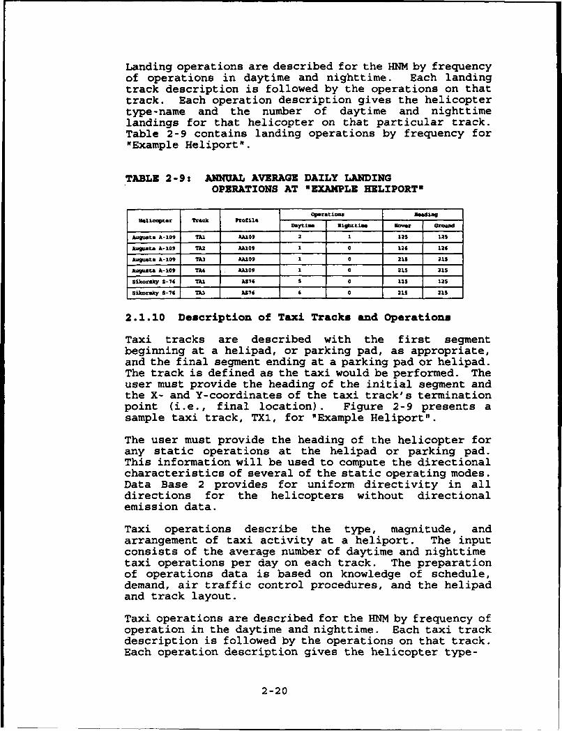
Landing operations are described for the HNM by frequencyof operations in daytime and nighttime. Each landingtrack description is followed by the operations on thattrack. Each operation description gives the helicoptertype-name and the number of daytime and nighttimelandings for that helicopter on that particular track.Table 2-9 contains landing operations by frequency for"Example Heliport".
TABLE 2-9: ANNUAL AVERAGE DAILY LANDINGOPERATIONS AT NEXAMPLE HELIPORTO
Operatioms"Uelicngter Track Mcuilo
Daytime Mightltin Nover Ground
Augusta A-09 TAI AA109 2 1 12S L25
Augusta ,A-09 TA2 AA409 1 0 126 126
An•glast A-109 7X AA09 1 0 21S 21S
Augusta A-109 TA4 AA109 I 0 215 21S
Sikorsky S-76 TAI A76 s 0 125 12S
Sikorsky 8-76 TU3 AS76 6 0 21S 215
2.1.10 Description of Taxi Tracks and Operations
Taxi tracks are described with the first segmentbeginning at a helipad, or parking pad, as appropriate,and the final segment ending at a parking pad or helipad.The track is defined as the taxi would be performed. Theuser must provide the heading of the initial segment andthe X- and Y-coordinates of the taxi track's terminationpoint (i.e., final location). Figure 2-9 presents asample taxi track, TX1, for "Example Heliport".
The user must provide the heading of the helicopter forany static operations at the helipad or parking pad.This information will be used to compute the directionalcharacteristics of several of the static operating modes.Data Base 2 provides for uniform directivity in alldirections for the helicopters without directionalemission data.
Taxi operations describe the type, magnitude, andarrangement of taxi activity at a heliport. The inputconsists of the average number of daytime and nighttimetaxi operations per day on each track. The preparationof operations data is based on knowledge of schedule,demand, air traffic control procedures, and the helipadand track layout.
Taxi operations are described for the HNM by frequency ofoperation in the daytime and nighttime. Each taxi trackdescription is followed by the operations on that track.Each operation description gives the helicopter type-
2-20

MAGNTIC ~TRUENOT M NOM
(is-VARIATIONO)
"EXAMPLE HELIPORT"
TOUCH DOWN. ...... , PAD P01
<110 FT. 0 195" W.
S100 FT. TURN RADIUS TOWN DOWN•/ -' ... ",, PAD PP1
TXl "'
FIGURE 2-9: ILLUSTRATION OF TAXI TRACK AT "EXAMPLE HELIPORT"
2-21
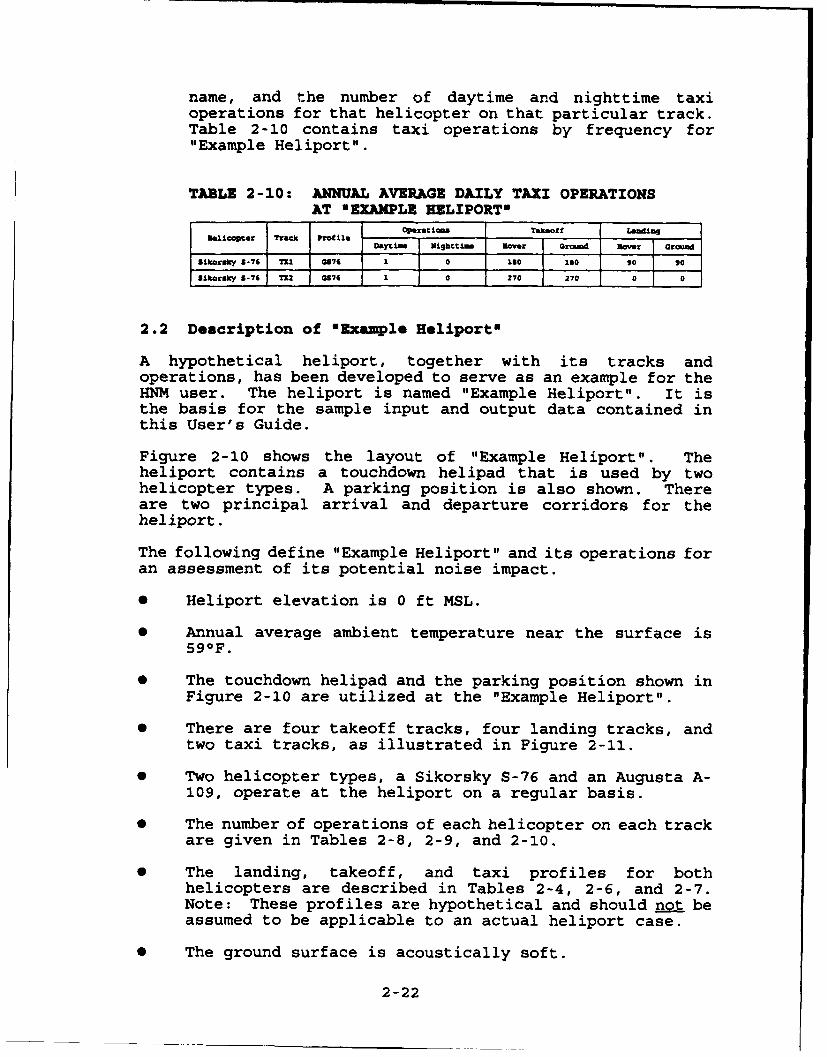
name, and the number of daytime and nighttime taxioperations for that helicopter on that particular track.Table 2-10 contains taxi operations by frequency for"Example Heliport".
TABLE 2-10: ANNUAL AVERAGE DAILY TAXI OPERATIONSAT NEXAMPLE EELIPORTN
Operationm saott LaTdengHelicopter TraCk rof ile
Daytime Nighttime flavor Ground Roaver around
Sikora"y 8-76 Tfl 6876 1 0 Igo 1 Igo 90 90
Sikora"y 5-76 712 Q875 1 0 270 270 0 0
2.2 Description of "Example Heliportm
A hypothetical heliport, together with its tracks andoperations, has been developed to serve as an example for theHNM user. The heliport is named "Example Heliport". It isthe basis for the sample input and output data contained inthis User's Guide.
Figure 2-10 shows the layout of "Example Heliport". Theheliport contains a touchdown helipad that is used by twohelicopter types. A parking position is also shown. Thereare two principal arrival and departure corridors for theheliport.
The following define "Example Heliport" and its operations foran assessment of its potential noise impact.
* Heliport elevation is 0 ft MSL.
* Annual average ambient temperature near the surface is590 F.
* The touchdown helipad and the parking position shown inFigure 2-10 are utilized at the "Example Heliport".
0 There are four takeoff tracks, four landing tracks, andtwo taxi tracks, as illustrated in Figure 2-11.
* Two helicopter types, a Sikorsky S-76 and an Augusta A-109, operate at the heliport on a regular basis.
* The number of operations of each helicopter on each trackare given in Tables 2-8, 2-9, and 2-10.
* The landing, takeoff, and taxi profiles for bothhelicopters are described in Tables 2-4, 2-6, and 2-7.Note: These profiles are hypothetical and should not beassumed to be applicable to an actual heliport case.
0 The ground surface is acoustically soft.
2-22

II;I.
cc* !b
II
W'4
II,
ccO9L
Uji
0.
2-2
/w
/I
~ Io
2-23

MAGNETIC TRUENORTH (U) NORTH(Is-VARIATIOhN)
TD4
TD2 TA4 TA3 TD3
TA2 .. ... * - -------------.... •----
TAI TD1
HELIo•r,
NOTE: TXI IS FROM PARKINGPAD (P01) TO PARKING PLACE
TX2 IS FROM PARKINGPLACE (PP1) TO PAD
FIGURE 2-11: TAKEOFF AND LANDING TRACKS AT 'EXAMPLE HELIPORT'
2-24

3. PROGRAM START-UP AND PREPARING CASE INPUTS
This section describes HNM Version 2.2 start-up and heliportcase study preparation. Case preparation is presented in aconcise step-by-step fashion and is accompanied by HNM screenexamples.
3.1 System Start-Up: The HNM Main Menum
The Heliport Noise Model Version 2.2 is executed by typingHNMRUN from within the HNM22 subdirectory.
0 c:\mG22\mI2m\M
Initially the "HNM Title Screen" is displayed. Selecting anykey will then bring up the "HNM Main Menu", Figure 3-1. Theuser may scroll through the available options within this menuand all subsequent menus described herein using the up/downand left/right arrow keys. From within the "HNM Main Menu"and all other menus context-sensitive help is available to theuser by selecting "F1".
With the "HNM Main Menu" displayed on the screen the user hasthe following four options:
Case Selection: A case must be selected before a usercan edit/load a case study. The "Case Selection" optionmust be chosen and either an existing or a new case studyshould be selected (see Section 3.2).
Edit/Load Case: Executing the "Edit/Load Case" optionallows the user to edit HNM input parameters, (e.g.,Setup, Pad/Parking Place, Helicopters, etc.) and to loadthe edited case for processing (see Section 3.3).
Process Case: The "Process Case" option executes theHNM's INPUT, FLIGHT and COMPUTE modules for a user-specified input case, (i.e., a user-specified case thathas been prepared and saved using the "Edit/Load" option)(see Section 3.4).
Plot Case: This menu option executes the HNMPLOT moduleto plot the noise contour for the processed case (seeSection 3.5).
The above options from the "HNM Main Menu" are discussed infurther detail in the following sections.
3-1

Selected Case
EDIT/LOAD CASE
PROCESS CASE
PLOT CASE
- -1M
FIGURE 3-1: HNM MAIN MENU
3.2 Case Selection
Upon selecting this option, the "Case File Selection Menu"will be displayed on the screen (Figure 3-2). The user hasthe option to: (1) select an existing case study; or (2)create a new study from scratch or use an existing case as amodel.
To select an existing case study, move the cursor to thedesired filename and select "ENTER" and "F10". A small windowwill appear on the display to verify the selection. Select"F10" to continue with the selected case which will be savedunder its displayed name. To create a new case using theselected case as a model, type a new "Save Case File" name andselect "F10". Upon selecting "F10", the data in the user-specified file is loaded into memory, and the "HNM Main Menu"will again be displayed. Note: The "Save Case File" namemust be changed if the user does not want to overwrite theoriginal file.
To create a new case study from scratch select "F10" with the"Case File Selection Menu" displayed. A small window appearsand the "Load Case File" name and "Save Case File" nameentries will be blank. Enter a filename for the "Save CaseFile" and select "F10". Any valid DOS filename (up to eightcharacters, optionally followed by a one-to-three characterextension) can be used. A new case study is created usingdefault values under the selected "Save Case File" name.
3-2

Load Case Sau CaseNow. Date Tim ham Date Tim
11/38/o93 18:42:84
FlHl F4-Dlt Fil F1-oniu Es Exi 4 - - I Mn Move-
FIGURE 3-2: CASE FILE SELECTION MENU
3.3 Edit/Load Case
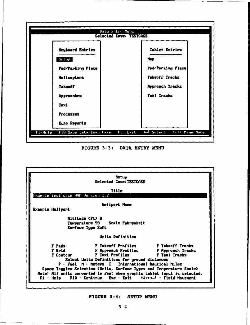
Upon selecting this option, the "Data Entry Menu" will bedisplayed on the screen (Figure 3-3). All data entry stepsbegin and end with this menu. These steps are shown in twocategories: (1) "Keyboard Entries" on the left; and (2)"Tablet Entries" on the right. As mentioned earlier inSection 1, the "Tablet Entry" option has been disabled. Tomake a selection from the "Data Entry Menu", highlight thedesired function and select "ENTER". In general, data entryshould proceed in the order in which the steps are shown inthe menu. Upon completion select "F10" to save the input filewith a .INP filename extension and the case file with a .ENTextension.
The user has the following data entry options:
Setu_ : The "Setup Menu" (Figure 3-4) allows the user tochange heliport parameters and units definition. Thismenu is used to enter information identifying the caseand the heliport under study, including: (1) Title - anydescriptive name up to 67 characters; (2) Heliport Name -any descriptive name up to 35 characters; (3) AltitudeAbove Mean Sea Level (MSL); (4) Temperature in Centigrade(C), Fahrenheit (F), or Rankine (R) degrees; (5) SurfaceType (i.e., hard or soft - currently soft is the only
3-3
Selected Case: TESTCASE
Keyboard Entries Tablet Entries
Mlap
Pad/Parking Place Pad/Parking Place
Helicopters Takeoff Tracks
Takeoff Approach Tracks
Approaches Taxi Tracks
Taxi
Processes
Echo Reports
FIGURE 3-3: DATA ENTRY M
SetupSelected Case:TESTCASE
Title
Heliport NawExanple Heliport
Altitude (Ft) 0Temperature 59 Scale FahrenheitSurface Tgpe Soft
Units Definition
F Pads F Takeoff Profiles F Takeoff TracksF Grid F Approach Profiles F Approach TracksF Contour F Taxi Profiles F Taxi Tracks
Select Units Definitionx for ground distancesF - Feet IM - heters I - International Nautical Miles
Space Toggles Selection (Units, Surface Types and Temperature Scale)Note: All units converted to feet uhen graphic tablet input is selected.Fl - Help FIB - Continue Esc - Exit t4.-4-J - Field Movement
FIGURE 3-4: SETUP MENU
3-4

valid selection); and (6) Units definition in ft, m ornm.
Upon completion, enter "FlO" to save or "ESC" to exitwithout saving.
Pad/Parking Place: The "Helipad Definition Menu" (Figure3-5) allows the user to define Pad/Parking identificationnames and X-,Y-coordinates of the pads in feet.
Helipad and parking locations are defined by firstentering an identifier, up to three letters/characters incombination, e.g., P01 and PP1, for each helipad andparking location. The X- and Y-coordinates should thenbe entered. Normally the helipad (or main helipad, ifthere is more than one at the heliport) is assigned thecoordinates (0,0); the other helipads are assignedcoordinates relative to that point.
Upon completion, enter "Fl0" to save or "ESC" to exitwithout saving.
Hglicojters: The "Helicopter Selection Menu" (Figure 3-6)allows the user to identify specific helicopters forprocessing. With this menu displayed, the "Space Bar" isused to select/deselect any number of helicopters fromthe list. A helicopter is selected when it ishighlighted in yellow. Nominal rotor RPM values arealso displayed for each helicopter. They may be modifiedas appropriate. If a helicopter is deselected, all otherentries relating to that helicopter will be erased.
Note: At least one helicopter must be selected for HNMcomputations to be performed. The following helicopters,although listed as available choices, do not haveacoustic data in the Data Base and cannot be selected forprocessing: S64, B47, BK117, H300C, and R22HP.
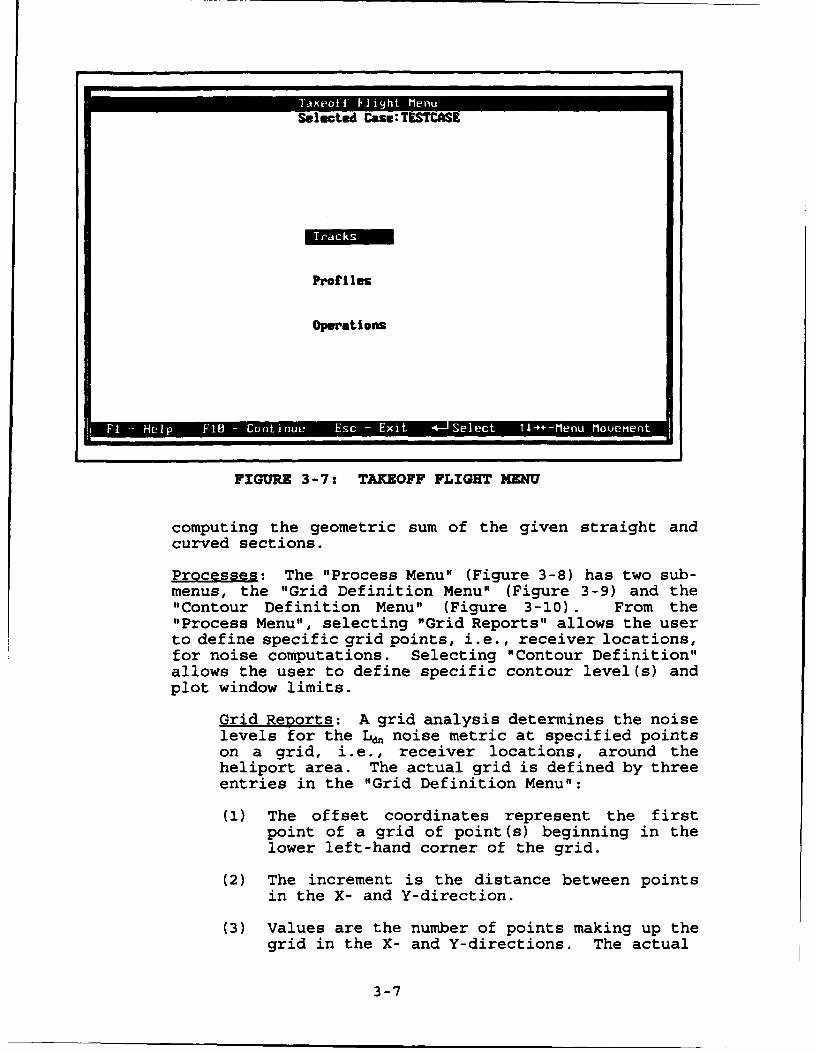
Takeoff: The "Takeoff Flight Menu" (Figure 3-7) hasthree sub-menus which allow for the editing of takeofftracks, profiles, and operations. Selection of theseitems from the menu is described further in Section 3.3.1below.
Apvroach: The "Approach Flight Menu" is identical totakeoffs (see Figure 3-7 and Section 3.3.1 below).
Taxi: With one exception, the "Taxi Flight Menu" isidentical to takeoffs (see Figure 3-7 and Section 3.3.1below). The exception is as follows: For properprocessing of taxi tracks, the geometric sum of thestraight and curved sections must equal the "FinalLocation". The "F3" option facilitates the adjustment ofsegment definition to match the "Final Location" by
3-5

Helipad DefinitionSelected Case: TES= E
Coordinates (Feet)Pad/Parkling Id. X V
Ppl 219.0 -218.08.8 8.00.8 8.8
9.8 8.88.8 8.0
8.8 6.89. 9 0.60.8 9.8
0.8 8.8
Fl-Help F16-Continue Esc-Exit ftl&4- i-Field Houenent
FIGURE 3-5: HELIPAD DEFINITION MENU
Helicopter SelectionSelected Case: TESTCASE
Helicopter Rotor Helicopter RotorName Description RPM Nae Description RPM
BZ1Z BELL 21Z (UH-1N) 324 S61 SIKORSKY S-61(CH-3A) Z83S64 SIKORSKY S-64(CH54B) 186 CH47D BOEING UERTOL CH-47D Z25H500D HUGHES 596D 49Z B0185 BOELKOU B0-185 424B47G BELL 47G 378 SA33W AEROSPATIALE SA-338J 265BZ86L BELL 286L 394 A1M9 AGUSTA A-109 385SA341G AEROSPATIALE SA-341G 378 H3SWC HUGHES 308C 471SGS SIKORSKY S-65(CH-53) 8 S?8 SIKORSKY S-78(UHG8A) 285S76 SIKORSKY S-76 293 SA365H AEROSPATIALE SA-3651H 365SA355F AEROSPATIALE SA-355F 394 SA358D AEROSPATIALE SA-358D 386BZ2Z BELL ZZZ 348 RZZHP ROBINSON RZZHP 538BK117 BOELKOU BK-117 391
Select Helicopters to be used for this Case.Selected Helicopters are displeaed in Yellou
Fl-Help FIB-Continue Esc-Exit tI4+4-J-Field Mlouement Space-Select
FIGURE 3-6: HELICOPTER SELECTION MENU
3-6
Selected Case:TESTCSE
Profiles
Operations
F1 Hl 1 -Cniu Es - Exi 4 -JSI c 1 - euM em
FIGURE 3-7: TAKEOFF FLIGHT MENU
computing the geometric sum of the given straight andcurved sections.
Processes: The "Process Menu" (Figure 3-8) has two sub-menus, the "Grid Definition Menu" (Figure 3-9) and the"Contour Definition Menu" (Figure 3-10). From the"Process Menu", selecting "Grid Reports" allows the userto define specific grid points, i.e., receiver locations,for noise computations. Selecting "Contour Definition"allows the user to define specific contour level(s) andplot window limits.
Grid Reports: A grid analysis determines the noiselevels for the Ldn noise metric at specified pointson a grid, i.e., receiver locations, around theheliport area. The actual grid is defined by threeentries in the "Grid Definition Menu":
(1) The offset coordinates represent the firstpoint of a grid of point(s) beginning in thelower left-hand corner of the grid.
(2) The increment is the distance between pointsin the X- and Y-direction.
(3) Values are the number of points making up thegrid in the X- and Y-directions. The actual
3-7

Selected Case: TESTCASE
Contour Definition
FIGURE 3-8: PROCESS MENU
Grid DefinitionSelected Case: TESTCASE
Grid X-Of fset V-Offset X-Incre,,ent V-Increm~nt X-Ualuez YV-alues Detail81 -1Z6.B 2686.8 208.8 11 11 N82 Z8. 2 96. 9 m .8. 8.9 1 1 N03 9.9 8.8 9.8 8.8 1 1 N84 m8596 N97 N88 N899i8s11 N12 N13 N14N15 N16 N1? N1is19N
F1 - Help 74 -Delete FI8 - Continue Esc -Exit MI.4I-tenu Mlovement
FIGURE 3-9: GRID DEFINITION MENU
3-8

Contour DefinitionSelected Case:TESTCASE
Contour Ham.:Contour Levels (dB):
68.0 65.8 76.9 9.9 O.O6.9 0.0 8.9 9.9 8.9
Tolerance: 1.0 Number of Refinements: 4
Uindou Coordinates (Feet):Louer Left - X -2668.0 6 V -2M.0.8Upper Right- X 2989.9 - Y 2669.8
Print Report V Contour Plot Y
Contour Plot Inforiation (Feet):
Paper Size( X -: 8.5 V - 11.8Plot Scale 186.9Plot Origin X - 6.6 Y - 8.8(6.8 , 6.9 places the origin at the center.)
Fl-Help FIB-Continue Esc-Exit t1464-J-Field Iovegent Space-Toggle
FIGURE 3-10: CONTOUR DEFINITION MENU
number of points in the grid is the product ofthe number of X-values and the number of Y-values. The user should enter 1 for both theX- and Y-values to define a grid with a singlepoint.
The normal output from the grid analysis is a"Standard Grid Analysis Report" (See Section 5).In addition to this report, the user may elect toreceive a "Detailed Grid Analysis Report," of up to20 points, i.e., receiver locations. Any number ofgrid analyses may be requested in one execution.
Contour Definition: A contour analysis determinesa recursively subdivided grid of points from whichcontours of selected values of Ld may be extractedin the area around the heliport. For example, ifthe user defines a contour value of 75 dB, the areaenclosed by the contour will have an Ld at or above75 dB. The user must specify at least one level.Contour files are saved with a filename extensionof .F33 added to the case name and may be retrievedduring subsequent use of the HNM.
The user may also specify a contour value"Tolerance", i.e., the measure of smoothness of thecontour line(s). Tolerance in dB indicates the
3-9

section of the heliport noise surface which willrequire more detailed computations. The defaulttolerance is ± I dB, and the user may change thisto any desired value. If, for example, the minimumrequested contour value is 65.0 and the pointsbeing checked have values of 63.1 and 66.2, thenthe area around this point will be subdividedfurther to produce more points at which to computenoise levels. Smaller tolerances result inadditional computations and may greatly increasethe HNM's run-time.
"Number of Refinements" determines the distancebetween receiver locations based on the measurementwindow selected. A higher refinement means closerspacing and yields smoother, more precise contours.Higher refinement levels also increase computationtime. Refinement can be set from three to seven.
The user can also specify the rectangular area,i.e., "Window Coordinates", within which thecontour computations are to be restricted. Thewindow is defined by the X- and Y-coordinates ofits lower left and upper right-hand corners. Allfour window coordinates must be specified if thisuser option is selected. A window with 4,000 ftsides centered around the origin is recommended.
The user may select one or two types of reportsfrom the "Contour Definition Menu". The "PrintReport" option generates a tabulation of the pointswhich define the contours. The "Contour Plot"option generates a graphic plot of the contours.
The "Contour Plot Information" option allowsadditional user input. The user may specify thepaper X-axis and Y-axis lengths, the plot scale,and plot origin point. The X-axis length is thesize of the paper along the X-axis. Similarly, theY-axis length is the size of the paper along theY-axis; the default size is 8.5 by 11 in. The plotscale is in ft per inch, and defaults to 1000 ftper inch. The plot origin position (X,Y) in inchesrelative to the lower left-hand corner of the paperis entered. If no origin is specified, the centerof the paper is selected as the origin.
Echo Reports: The "Echo Reports" option allows the userto reproduce specific input information so thatcorrectness can be verified. With the "Echo ReportsMenu" displayed, the "Space Bar" is used toselect/deselect specific reports.
3-10

3.3.1 Takeoff/Approach/Taxi Flight Menu
The HNM requires information about helicopter takeoff,approach, and/or taxi activities at the heliport. In eachcase, it is necessary to define ground tracks and flightprofiles, and to enter information on the number of operationsassociated with each track and profile for the helicoptersselected. This is a relatively involved process for a busyheliport, but the HNM allows the information to be entered ina straightforward and systematic way. The entry of data ontakeoff activities is described in this section. The entry ofdata on approach and taxi activities is essentially identical;the one exception for taxi is noted in Section 3.3 above.
Tracks: The "Takeoff Track Selection Menu" (Figure 3-11)allows the user to define helicopter takeoff tracks orselect existing tracks for editing. To define a newtrack the user must first select "F3" to add a track;similarly, the user may delete an existing track byselecting "F4". Njot: If a track to be deleted isalready specified in the "Operations Menu", theoperations must first be deleted from the track.
To edit a new or previously existing track the trackshould be highlighted and "ENTER" should be selected.Once the track is selected the "Takeoff Track SegmentDefinition Menu" is displayed (Figure 3-12). Whenentering segment information, certain rules are enforcedbefore the data can be saved:
(1) The track must start and end with a straightsegment having a length greater than zero.
(2) The heading of the initial straight segmentmust be specified.
(3) If a curve segment is specified, the change inheading/angle between segments must be greaterthan zero.
A takeoff ground track must start at a designated helipadwith a straight segment and an initial heading. User-specified curved and straight segments can then follow.Straight segments are defined simply by their length inuser-specified units. A curved segment requires threeentries: (1) the turn, to the left or right; (2) theturn angle or a heading; and (3) the radius of the turn.
Upon completion, enter "Fl0" to save or "ESC" to exitwithout saving.
3-11

Taef Trc eecinMn
ISelected Cass:TESTCASE
jltdZ td3 td4
VS.el dJfd .ADlt -l-aeCnineEcE -*elc SIMu
FIGURE 3-11: TAKEOFF TRACK SELECTION MENU
Takeoff Track Segm'ent Definition
Selected Case: TESTCASE
Track:= Pad: Pol Initial Heading 305 (Deg.)
Straight:Za (Ft.)Curved.Right 99 (Deg.) Heading Radius.688 (Ft.)Straight:9999 (Ft.)Curved: 9 (Deg.) Radius:8 (Ft.)Straight:@ (Ft.)Curved: 9 (Deg.) Radlus:B (Ft.)Straight:S (Ft.)Curved: 0 (Deg.) Radius:8 (Ft.)Straight:@ (Ft.)Curved: 93 (Deg.) Radius:O (Ft.)Straightme (Ft.)Curved: 13 (Deg.) Radius:S (Ft.)Straight:8 (Ft.)Curved: 8 (Dug.) Radius:83 (Ft.)Straightl8 (Ft.)
Fl-Help FIS-Saue/Continue Esc-Exit tI-- 1 -Field hlove Space-Toggle
FIGURE 3-12: TAKEOFF TRACK SEGMENT DEFINITION MENU
3-12

Profiles: After selecting "Profiles" from the "TakeoffFlight Menu", the "Takeoff Profile Helicopter SelectionMenu" is displayed (Figure 3-13). The user shouldhighlight the desired helicopter and select "ENTER". The"Takeoff Profile Selection Menu" is displayed (Figure 3-14) and a list of applicable profiles is given for thehelicopter. To add a new profile the user must firstselect "F3"; similarly, the user may delete an existingprofile by selecting "F4". Note: If a profile to bedeleted is already specified in the "Operations Menu",the operations must first be deleted.
To edit a new or previously existing profile it should behighlighted and "ENTER" should be selected. Once theprofile is selected, the "Takeoff Profile DefinitionMenu" is displayed (Figure 3-15). When entering profileinformation, certain rules are enforced before the datacan be saved:
(1) BLANKS and VOID are not valid for
"Mode".
(2) "Duration/Speed" must be greater than zero.
(3a) Takeoff: At least three segments must bespecified; and distances and altitudes must bein ascending order.
(3b) _Ay: At least three segments must bespecified; and distances and altitudes must bein descending order.
(3c) Taxi: At least three takeoff and threeapproach segments must be specified; and theymust be connected by a common 5280 ft segment.
For each segment of a helicopter profile, the user willbe required to provide the following four items: (1)operating mode (thrust name); (2) ground distance of thepoint from start of the operation in user specified units(ft, m or nm); (3) altitude in ft above the heliport; and(4) the velocity in knots (kt) at the point or, forstatic operations, duration in seconds of the operationat the point.
Upon completion, enter "F10" to save or "ESC" to exitwithout saving.
Operations: After selecting operations, the "TakeoffOperations Definition Menu" is displayed (Figure 3-16).An operation is defined by selecting a "Helicopter","Track", "Profile", and the number of "Operations" duringeither the day (0700 to 2200 hours local time) or night(2200 to 0700 hours local time). When the cursor is on
3-13

Selected Case: TESTCASE
S76 SIKORSKY S-76
F HF IB Es - -- M
FIGURE 3-13: TAKEOFF PROFILE HELICOPTER SELECTION MENU
Selected Case: TESTCASE
Helicopter : A189 - AGUSTA A-109
FIGURE 3-14: TAKEOFF PROFILE SELECTION MENU
3-14

Takeoff Profile DefinitionSelected Case: TESTCASE
Helicopter:A109 AGLJSTA A-l09 Proflle:
Mode Distance Altitude Duration/Speed
HIGE 8.96 6. 8 30.86 (Sec.)HIGE 8.66 6. 8 36.60 (Sec.)UASC . Ne 9. 8 3.66 (Sec.)ACLH 6.66 15.66 16.86 (Kts.)ACLC 16. 6e 15.86 36.68 (Kts.)
TO 56Z.e8 36.86 66. 6 (Kts.)TO 483Z.08 16688.6 68.66 (Nts.)
LFLO 6786.66 1866.66 168.88 (Kts.)99999. 8 1666.06 166.86 (Kts.)
0.66 9.66 8.66 (Kts.)8.66 6.66 8.66 (Kts.)6.66 6.66 0.86 (Kts.)6.66 6.66 8.66 (Kts.)8.66 6.66 0.66 (Kts.)
Fl-Help F4-Delete F18-Save/Continue Esc-Exit t14+4-I-Field "ove Space-Toggle
FIGURE 3-15: TAKEOFF PROFILE DEFINITION MENU
Takeoff Operations DefinitionSelected Case: TESTCASE
Helicopter Track Profile Operations HeadingDag Night Hover Ground
tdl TA189 Z. 8 1.8 380 368AGUSTA A-189 tdZ TA19 1.9 8.8 -99 299AGUSTA A-109 td3 TA19 1.8 9.9 33 33AGUSTA A-109 td4 TA19 1.8 6.8 3Z 32SIKORSKY S-76 tdl TS76 5.6 9.8 388 386SIKORSKY S-76 td3 TS76 5.6 6.9 33 33
8.9 9.8 8 86.8 8.8 6 98.8 9.8 8 98.8 8.0 6 69.6 9.8 8 96.8 8.8 8 6
8.6 9.9
6.9 6.8 6 8
Fl-Help F4-Delete F1O-Save/Continue Esc-Exit tUl-4- -Field Hove Space-Toggie
FIGURE 3-16: TAKEOFF OPERATIONS DEFINITION MENU
3-15

the "Helicopter", "Track", or "Profile" field, aselection is made by using the "Space Bar" to togglethrough the available choices. Certain rules areenforced before an operation can be saved:
(1) A track and profile must be specified or theentry must be deleted with the "F4" key.
(2) Total operations must be greater than zero.
Upon completion, enter "FI0" to save or "ESC" to exitwithout saving.
3.4 Process Came
After selecting "Process Case" from the "HNM Main Menu" a casestudy can be selected for processing by moving the cursor overthe desired filename and selecting "ENTER" and "Flo". Allcase studies that appear in this menu have been previouslyloaded/edited and saved (having a filename with a .INPextension) using the Flo key under "Edit/Load Case". As thecase study begins running, the processing status of INPUT.EXE,FLIGHT.EXE, and COMPUTE.EXE is displayed. When the currentrun is complete, a small window is displayed and variousoutput options are available to the user, including theviewing and printing of the "Echo Reports". When processingis completed a plot file is created with a filename containinga .F33 extension.
Note: All input file data are automatically verified by theHNM, and all warning messages are displayed and execution willproceed as requested from the "Process Case" option. The HNMdoes not have the "NO VERIFY", "NO EXECUTE", and "NO WARN"options of the INM.
3.5 Plot Case
After selecting "Plot Case" from the "HNM Main Menu" a casestudy is selected for plotting by moving the cursor over thedesired filename and selecting "ENTER" and "Fl0". All casestudies that appear in this menu have been previously createdwith the "F10" key under "Process Case" and have a filenamewith a .INP extension. After the plotting routine starts, the"HNM Plot Menu" is displayed. Selecting Fl displays a "HelpMenu" that describes the functions available with the plottingpackage. Note that the HNM plotting package is essentiallyidentical to the one used by the INM. Consequently, HNM usersseeking additional information on the contour plotting programare referred to the User's Manual for the INM contour plottingprogram.
3.6 Help
Context-sensitive help menus are provided for all screendisplays by selecting "Fl". The help menus are self-explanatory.
3-16

4. PROCESSING THE CASE
This section describes the HNM's processing of a user-selectedinput case, prepared as described in Section 3 above. The menu-driven, graphical user interface facilitates the preparation of aninput text file (HFOR02.DAT) similar to that required by the INM(FOR02.DAT). The input file for "Example Heliport", shown inFigure 4-1, is processed by the HNM in the following three steps:
0 Input Formatting* Flight Compilation0 Noise Level Computations
The above steps are performed automatically on a user-selectedinput file, i.e., case study, by selecting: (1) PROCESS CASE inthe "HNM Main Menu"; (2) a specific input file, one which carriesa filename with a .INP extension; and (3) the F10 key. To executethe above three program steps separately, perform the followingprocedures exclusive of the HNM menu-environment: (1) rename thesubject input text file to HFOR02.DAT; (2) execute INPUT.EXE,FLIGHT.EXE, and COMPUTE.EXE; and (3) execute HNMPLOT.EXE to viewthe computed contour.
4.1 The Input File
The majority of the errors which can occur in creating aninput file using a text editor, as with the INM, areeliminated using the HNM's menu-driven entry process.However, some errors of omission can still occur.
Each input file, i.e., case study, must contain the followingdata sections:
(1) SETUP: contains heliport descriptions and helipaddata.
(2) AIRCRAFT: selects or defines the helicopter types.(3) TAKEOFFS: describes takeoff tracks, and defines takeoff
operations by frequency.(4) LANDINGS: describes landing tracks, and defines landing
operations by frequency.(5) TAXI: describes taxi tracks, and defines taxi
operations by frequency.(6) PROCESS: describes the analysis processes to be
performed on the input case.
An exception to the above requirement is the situation whereonly one or two types of operations are included in thescenario. In this case, the user may omit any two offollowing three sections: TAKEOFFS, LANDINGS, or TAXIS.However, the input data must include at least one of thesesections; and for each section that is included, at least oneoperation.
4-1

MOECHO.
TITLE Exaumple test came UM Version 2.2ýAIRPORT axfample HeliportALTITUDE 0. T3MPERATURE 59.00 F SURFACE S Note: If a heliport altitude and
MOECHO. temperature are not specified, defaultFT. values of 0 ft NSL and 59sF, respectively,
RUNWAYS will be assumed. In addition, "S'oftRU Pol 0. 0. TO 0. 1. HEADING-360 surface type is the only valid selectlon.RW Ppl 210. -210. TO 210. -209. HEADING-360
NMOCHO.AIRCRAFT:
TYPESAC A109 ROTOR 385 CURVE Al09 CATEGORY HCOM
STAGE I-TA09STAGS 2-GA109
AC 876 ROTOR 293 CURVE 876 CATEGORY HCO4STAGE I-TS76STAGE 2-GS76
NOECHO.FT.
PROFILES APPROACHPP AA109 SEGMENTS- 7 Note: prom 3 to 14 approach profile
DISTANCES 99998. 10535. 4819. 3062. 0. 0. 0. segments are allowed.ALTITUDES 1000. 1000. 1000. S00. 3. 0. 0.
SPEEDS 100.00 100.00 60.00 60.00 3.00 60.00 0.00THRUSTS LFLO DCLS APPR DCLD HIGS RIGS
PP AS76 SEGMENTS. 7DISTANCES 99998. 10535. 4819. 3062. 0. 0. 0.ALTITUDES 1000. 1000. 1000. 500. 3. 0. 0.
SPEEDS 100.00 100.00 60.00 60.00 3.00 60.00 0.00THRUSTS LFLO DCLH APPR DCLD HIGH HIGS
PP GS76 SEGMENTS- 5 Note: This entry is an example of the finalDISTANCES 5280. 0. 0. 0. 0. profile phase for a taxi operation.ALTITUDES 3. 3. 0. 0. 0.
SPEEDS 10.00 10.00 10.00 60.00 0.00THRUSTS HIGH HIGH HRIG GIDLE
NOECHO.
FT.PROFILES TAKEOFF
PP TAI09 SEGIMENTS. 9 WRIGH-T- 5632 ENGINES- I Note: Prom 3 to 14 takeoff profile segment*DISTANCES 0. 0. 0. 0. 100. 562. 4032. are allowed.
6786. 99999.ALTITUDES 0. 0. 0. 15. 15. 30. 1000.
1000. 1000.SPEEDS 30.00 30.00 3.00 16.00 30.00 60.00 60.00
100.00 100.00THRUSTS HIGS HRIG VASC ACLH ACLC TO TO
LPLOPP TS76 SEGMENTS- 9 WRIGHT. 9984 ENGINES- 1
DISTANCES 0. 0. 0. 0. 100. 562. 4032.6786. 99999.
ALTITUDES 0. 0. 0. 15. 15. 30. 1000.1000. 1000.
SPEEDS 60.00 30.00 3.00 16.00 30.00 60.00 60.00100.00 100.00
THRUSTS GIDLE HIGE VASC ACLH ACLC TO TOLFLO
PP GS76 SEGMENTS- 4 WEIGHT. 9984 NGZINES- 1 Note: This entry is an example of theDISTANCES 0. 0. 0. 5280. initial profile phase for a taxi operation.ALTITUDES 0. 0. 3. 3.
SPEEDS 60.00 30.00 10.00 10.00THRUSTS GIDLE HIGS HIGE
NOECHO.FT.
TAKEOFFS BY FREQUENCY:TRACK tdl RUY Pol HEADING 305
STRAIGHT 280.00RIGHT 90 H 600.00STRAIGHT 9999.00
OPER A109 STAGE 1 D 2.00 N 1.00 GHDT 300 HHDT 300OPER 976 STAGE I D S.00 GHDT 300 HHDT 300
TRACK td2 RRY PO1 HEADING 305STRAIGHT 280.00RIGHT 320 H 600.00STRAIGHT 9999.00
OPER A109 STAGE 1 D 1.00 GHDT 299 HHDT 299TRACK td3 RWY Pol HEADING 35
STRAIGHT 200.00LEFT 350 H 600.00STRAIGHT 200.00RIGHT 90 H 600.00STRAIGHT 9999.00
OPER A109 STAGE 1 D 1.00 GHDT 33 HEDT 33OPER S76 STAGE 1 D 6.00 GEDT 33 HHDT 33
FIGURE 4-1: INPUT TEXT FILE FOR 'EXAMPLE HELIPORT3 CASE STUDY
4-2

TRACK t64 it1 Pol HEADING 3S c58m :8TRAIGHT 200.00LEFT 320 H 600.00STRAIGHT 9999.00
OVER A109 STAGE 1 D 1.00 GHDT 32 T 32MOS~CHiO.
FT.LANDINGS by FREQUENCY:TRACK tel RWY P0l HEADING 270
STRAIGHT 9999.00LEFT 122S 600.00STRAIGHT 260.00
OPUS A109 P.OI-A£109 D 2.00 N 1.00 GHDA 125 SKDA 12SOVER 876 PROPAS76 D S.00 GHDA 125 SMDA 12S
TRACK ta2 RMY P0l HEADING 140STRAIGHT 9999.00L•FT 12s H 600.00STRAIGHT 260.00
0P33 A109 PROF-AA109 D 1.00 GBDA 126 EWA 126TRACK ta3 RUY Pol HEADING 270
STRAIGHT 9999.00LEFT 170 H 600.00STRAIGHT 200.00RIGHT 215 H 600.00STRAIGHT 200.00
OPEn £109 PROF-AA409 D 1.00 G0DA 21S M3A 21SOPRl S76 PROP-AS76 D 6.00 GHDA 21S HHDA 215
TRACK t&4 R3Y P1a HEADING 140STRAIGHT 9999.00RIGRT 21S H 600.00STRAIGHT 200.00
OPER A109 PROP-AA109 D 1.00 GMDA 215 HHDA 215NOSCHO.FT.TAXIS BY FREQUENCY:
TRACK txl R3y Poi 210.0 -210.0 HEADING 160STRAZGHT 110.00LEFT 90 H 100.00STRAIGHT 110.00
OPER 876 STAGE 2 PROP-GS76 D 1.00GHDT 160 HhYr 180 GUDA 90 MMA 90
TRACK tx2 RWY Ppl 0.0 0.0 READING 270STRAIGHT 110.00RIGHT 0 H 100.00STRAIGHT 110.00
OPER S76 STAGE 2 PROP-GS76 0 1.00G1HVT 270 H]DT 270 G0DA 0 HiDA 0
PROCESS:FT.
GRID LWN START- -1200. -1200. STEP- 200. 200.SIZZB- 11 BY 11
GRID LDN START- 200. 200. STEP- 0. 0.SIZE- 1 BY 1
GRID LDN START- 0. 0. STEP- 0. 0.SIZ3- I BY 1
FT.CONTOUR LDN AT 60.0 65.0 70.0 Note: If an LDN contour is not specified,
WITH NANE-NEW001 TOLERANCE-1.00 default values of 6S and 75 dB vill beXSTART. -2000. YSTART- -2000. XSTOP- 2000. YSTOP- 2000. assumed. In addition, if a refinement level3P.1N1. 4 or vindow size is not specified, defaultREPORT values of 6 (no units) and 4000 ft per sidePLOT SIZE- 6.5 11.0 SCALE- 1000. are assumed.
ORIGIN- 0.0 0.0END.
FIGUPE 4-1 (CONTINUED): INPUT TEXT FILE FOR "FiAMPLZ HELIPORT, CASE STUDY
4-3

4.2 Run-time Files
The HNM creates several files during execution. Most of thefiles can be erased from the hard disk after running a case.However, if future processing or analysis of a subject case isanticipated, the following two files should be renamed:
HFOR02.DAT: the Input File, i.e., case study, created forprocessing by HNM Version 2.2; and
FOR33.DAT: the Contour Points File created by the computemodule for input into the HNMPLOT Program.
Note: During execution these files are automatically renamedby the HNM to HFOR02.INP and FOR33.F33, respectively.
4.3 Error Messages
The HNM Input Formatting Module can produce a number ofwarning and fatal error messages. The output reports shouldbe checked for these messages and the input case should becorrected to be error free. To aid the user, as the InputFormatting Module begins to process a major section of input,it prints out a processing location message. For example, themessage "***PROCESSING SETUP SECTION" is printed prior to theprocessing of the section of the input text file which followsthe keyword "SETUP:". If a fatal error is detected by theInput Formatting Module, execution of the HNM terminatesimmediately. If warning errors are detected by the InputFormatting Module, no analyses will be performed on the dataand execution of the HNM terminates after execution of themodule.
The Input Formatting Module can also print out the input datain the form of "Echo Reportr", if that option is selected fromthe "Data Entry Menu". It i.- recommended that the user verifythat the information processed by the program is correct.
If the input case is acceptable to the Input FormattingModule, execution of the process commands will begin.However, all modules can produce warning and fatal errormessages. The execution printout should be checked for thesemessages. Section 4.4 and Appendix C describe these messagesand instruct the user as to the action to be taken when themessages are encountered. A fatal error within any one ofthese modules, except the Flight Compilation Module,terminates execution of that module only and not terminationof the execution of the HNM. Any fatal error during FlightCompilation will terminate the HNM. All fatal errors must beeliminated for proper execution. In addition, measures shouldbe taken to eliminate all warning messages, if possible. TheHNM does not contain the "NOWARN" option which exists in theINM. F`nally, the user should study the output reports andplots produced by the various modules, verify that the desiredanalyses were performed, and verify that the input dataproduced reasonable results.
4-4

4.4 Error Analymsi and Correction
Each module of the HNM produces its own error messages. Allare listed in Appendix C. These messages take the followingform:
Axx*FATAL: ....or
Axx*WARNING: ....
where, A is a one/two-letter prefix to indicatewhich module produced the message; theprefixes are as follows:
C - COMPUTATIONCN - CONTOURF - FLIGHT OVERLAYI - INPUTP - PLOTRG - REPORT GENERATOR
and xx is a unique number identifier forthe error.
A fatal message within the Input Formatting or FlightCompilation Modules causes termination of HNM execution. Afatal message within any other module causes control to bereturned to the Executive Module, which will attempt tocontinue the processing of modules, as directed by theprocessing template.
4.5 Data Base Reports
File FOR17.DAT is a user-accessible ASCII version of the DataBase. With the DOS prompt displayed on the computer display,the user may obtain a hardcopy of the Data Base by printingthe FOR17.DAT file.
4.6 Plots
The plot option from the "HNM Main Menu" allows the plottingof previously computed noise exposure contours. When thisoptior is selected, the "HNM Plot Menu" is displayed. Byselect.ing from this menu, the user may plot contours on thescreen or a plotter. The user can change the plot window,plot scale, or the centering of the origin of the plot. Withthe "HNM Plot Menu" displayed, selecting F1 initiates theonline "Help" facility which describes the functions availablewith the plotting package. Note that the HNM plotting packageis essentially identical to the one used by the INM.
4-5/4-6

5. INTERPRETING THE OUTPUT
The output of the HNM consists of printed reports and contourplots. Specifically, the Input Formatting Module produces "EchoReports" of the input data file; a "Grid Analysis" produces aprinted report of noise exposure at specific receiver locations onthe ground; and a "Contour Analysis" produces a report of receiverlocations with equal noise exposure and a plot of these contours.Section 3 describes how to obtain a copy of these reports. Thefollowing sections describe their contents.
5.1 Echo Reports
The Input Formatting module can produce up to nine EchoReports to provide the user with a quick means of detectingerrors in the input data. Figures 5-1 through 5-9 areexamples of these nine reports for "Example Heliport". Thereports, which are formatted with headers, areself-explanatory.
5.2 Grid Analysis
A grid analysis produces a standard tabular report, and anoptional detailed tabular report. Figure 5-10 is a sample"Standard Grid Analysis Report" for "Example Heliport".Following the report title, the case title and heliport name,as input by the user, is displayed. A table of noise valuesfor the specified grid points, i.e., receiver locations,follows. The grid point locations are listed under theheadings "X" and "Y" for X-coordinate and Y-coordinate,respectively. Under the Ln heading are the computed noisevalues for the particular grid point(s).
A maximum of 20 grid points may be specified in the "DetailedGrid Analysis Report". A separate page is printed for eachpoint. Figure 5-11 presents two pages from the detailedreport for "Example Heliport". The boxed area identifies theX- and Y-coordinates of the grid point, and the total noisevalue at the point. The next section of the report gives theindividual contributions made by the 20 flights making themost significant contribution to the total noise. A flight isdefined as a unique combination of a helicopter's track, type,and profile. A line of information is printed for eachflight, giving the following:
(1) Helicopter Name(2) Takeoff Profile Name for Takeoffs, or Approach Profile
Name for Landings(3) Noise Curve Name(4) "Stage", an Identification Number Assigned to the Type of
Profile (e.g., for "Example Heliport" Stage 1 and 2 inthe input file (Figure 4-1) refer to Takeoff and Taxi,Respectively; Stage 0 in Figure 5-11 refers to Approach)
(5) Taxi Approach Profile Name
5-1

MUMC~ Nola NWlL - am NMOR I
S3 P 8 TV 9MVRT I
TMIL 8sop.etes cas. UM Vorian~ 2.2
AliRpO msml N.1iport
ALTZ1fS C. 31.TUoolAIuS 516.7 R St. 0 r 15.0 C
sox=a mumcs
iDAY-miouT Avnh= mmUD IvIL tLum) - muI on Leo, WITH wimRVW oPmmooU UUimI wY A 10 CECimL vUIATy.
FIGURE 5-1: SAMPLE ECHO REPORT: SETUP
5-2

WUPCWT sox= "ME -I m LV T PU 2
a9i A v s AJiImomT 2
Sam 3 =ITSDZ X y MUMay
Dpol 360 1P 0. 0. 1.N 0. 0. 0.
3i4 .000 .000 .000
opt 360 li 210. -210. 1.N 64. -64. 0.All .035 -. 035 .000
FIGURE 5-2: SAMPLE ECHO REPORT: HEMLIPADS
5-3

IPurm miss N323 L - SO EXPORT mm 3
A I ac a A r T EXOR 3
MlOISSCURVE R0TOR TAKEO PROFILE MIANES
amRI CR0I0Y KNEE 8l 33 8IAM 8T13 STA8ET0483 ST035 STr03 81Mg
A3109 NCWI A09 365 TM809 GAi0SS76 3o 876 293 T876 Q876
FIGURE 5-3: SAMPLE ECHO REPORT: HELICOPTERS
5-4

APPROACH P1 I021 8 SBroMr 4
DI8TANUS FROM 3&ma w
U1i09 1 0. O. .00 .00 .00 3263
a 0. 0. .00 .00 60.00 HIGH
3 0. 0. .00 3.00 3.00 DCLD4 3"02. 933. .50 500.00 60.00 AM19
5 4619. 1469. .79 1000.00 60.00 DC.
6 103S5. 3211. 1.73 1000.00 100.00 low7 99996. 30479. 16.46 1000.00 100.00 law
A876 1 0. 0. .00 .00 .00 R3GS
2 0. 0. .00 .00 60.00 3026
3 0. 0. .00 3.00 3.00 DCLD
4 3062. 933. .s0 500.00 60.00 APPn
5 4519. 1469. .79 1000.00 60.006 10535. 3211. 1.73 1000.00 100.00 1.1O7 99996. 30479. 16.46 1000.00 100.00 1.1W
6876 1 0. 0. .00 .00 .00 aOWLS
2 0. 0. .00 .00 60.00 3L26
3 0. 0. .00 .00 10.00 3163
4 0. 0. .00 3.00 10.00 B103
S S260. 2609. .87 3.00 10.00 3I26
FIGURE 5-4: SAMPLE ECHO REPORT: APPROACH PROFILES
5-5

7&zlr130111 130- 1.$
T&RBOFF 9 R0OrI LI 2 s ,01T s
DIST1UC3 r1a0m am I=m
WQi INlGm ==103r g I1'1" N 031 ALTrm 4rr) $pm rn) .us.
MotU I• S6$32. 1 0. 0. .00 .00 30.00 KlQt
1 0. 0. .00 .00 30.00 3108
1 0. 0. .00 3.00 VUC
4 0. 0. .00 1S.00 16.00 A=
5 100. 30. .02 15.00 30.00 A=C
6 562. 171. .09 30.00 60.00 TO
7 4032. 122t. .66 1000.00 60.00 TO
I 6756. 2066. 1.12 1000.00 100.00 1.W
9 99999. 304$0. 16.46 1000.00 100.00 1.W
T876 1 9964. 1 0. 0. .00 .00 60.00 aIms
2 0. 0. .00 .00 30.00 SIGN
3 0. 0. .00 .00 3.00 VUC
4 0. 0. .00 15.00 16.00 Aria
S 100. 30. .02 15.00 30.00 ACL,
6 $62. 171. .09 30.00 60.00 TO
7 4032. 1229. .66 1000.00 60.00 TO
a 6766. 2068. 1.12 1000.00 100.00 L.W
9 99999. 30450. 16.46 1000.00 100.00 1LW
0876 1 9954. 1 0. 0. .00 .00 60.00 GyDm,3
2 0. 0. .00 ,00 30.00 HGim
3 0. 0. .00 3.00 10.00 K102
4 S280. 1609. .87 3.00 10.00 H32I
FIGURE S-S: SAMPLE ECHO REPORT: TAKEOFF PROFILES
5-6

II rT BoxIE NCo= - woo 0 P 6
TAl18EOF - TRACKS E I;0r6 - panT A
INITIAL LNMT TUNA ANOLS 3SURLT•NT TURN RADIUStdl P 30S 0 STRAIGHT .05 305
2 I(WT 145 to .103 ITRAIGIT 1.6s to
1d2 9l0 305 1 STRAIU•IT .0s 3052 £110rr 15 320 .103 STRPAIGT 1.65 320
Wd4 P01 3S 1 ITRAIU T .03 352 LiT 45 350 .103 STRAZIrT .03 3S04 £ItGT 100 t0 .10$ ST"IIwT 1.6S 90
td4 Pol 3S 1 STRAIUGW .03 3S2 LETF" 7S 320 .103 STRAIGHT 1.65 320
IRIRPORT NOISS NO RL - WH EN*lAT PAGE 7
TAKEOFF - O EERATIOuS 0IMPRT 6 PART 5
OPUIATI OWSTRACK RUIAY £3TE31A11 CLUSS STAGE PROFILE DAY EvInIMNG NIrr
tdl Pal A209 Am 1 Talo0 2.00 .00 1.00
S76 CON 1 T876 S.00 .00 .00
td2 Pol £109 CN4 1 TA109 1.00 .00 .00
td3 Pal A109 CON 1 TA109 1.00 .00 .00Ss CON 1 TS76 6.00 .00 .00
t64 Pol £L09 CON 1 TA109 1.00 .00 .00
HILIPOIT NOIS IV= - 1030 REP0T PAGE 8
TAKEOFF - DISTRIBUTZON 1316r1 - PART C
OPERtATIONfSDAY EVEIIN0G 31GM
CWMi•SC1 L - 16.0 .0 1.0
ONI1MAL AVIATION - .0 .0 .0
NzLIURtY - .0 .0 .0
PROPORTIONSE
COUSSRCIAL 0EWKRAL AVIATION MILITARYTRACK RUNMAY DAY EV3W30 NIGHT DAY EVINIXG NIGHT DAY ESVIIING NIGHT
td, P013 .44 .00 1.00 .00 .00 .00 .00 .00 .00td2 PFl .06 .00 .00 .00 .00 .00 .00 .00 .00td1 Pol .44 .00 .00 .00 .00 .00 .00 .00 .00t64 Pol .06 .00 .00 .00 .00 .00 .00 .00 .00
-- - - - - - - - - -............. ..... . .----. .------.. .... . ..... . .....TOM 1.00 .00 1.00 .00 .00 .00 .00 .00 .00
FIGURE 5-6: SAMPLE ECHO REPORT: TAKEOFF TRACKS AND OPERATIONS
5-7

SXIPORT NoISE NmSL E- DEPORT AWm 0
LAND1NG - TRACES RCU POT -7 A1RT A
INITIAL LIoT TURN AIA i IULTNr TiURN RADIUStat pal 305 1 ETRAIGNT .05 30s
2 SIGLT 145 90 .103 STR•AI• 1.6S 90
t&2 Pal 30S 1 ETrAIGNT .05 30S2 RIOET is 320 .103 STRYlAT 1.6S 320
Wa3 Pat 3S 1 STrtlor .03 352 1.31 45 3S0 .103 STRAJOEr .03 3S04 RIOrY 100 90 .105 STrA/IOTr 1.45 90
tA4 Pal 3s 1 STRAIIT" .03 352 LaEn 7S 320 .103 STRAIGHT 1.65 320
MLIP•RT MOIS mooL - amO UPORT pJh550
LAt D - f; - OPERATIONS 1PORT I 7- PART a
O0IRATIONSTRACK RumAy AIRCRAFT CLASS PROFILE DAY 'VYHING KxIOT
tal Pal A109 CON AML09 2.00 .00 1.00
876 con AS76 S.00 .00 .00
ta2 POl AS09 CON AMO0 1.00 .00 .00
tat Pal A09 con AMO1 1.00 .00 .00876 CON A7?6 4.00 .00 .00
ta4 Pol A109 CON A109 1.00 .00 .00
HZLIPORT MOISE MODEL - WH iIPORT PAG311
LANDING - D1STRI1UTION R10EIPOT 7 -PART C
OPERATIONS
DAY XMI'NG MIGET
C'0IEMCIAL - 16.0 .0 1.0
GIERDAL AVIATION - .0 .0 .0
MILITARY - .0 .0 .0
PROPORTIONS
CoWEmCIAL OSEDAL AVIATION MILITARYTRACK RUNMAY DAY EVENING NIGHT DAY EVININO NIGHT DAY EVVIING NIGDE
tal Pal .44 .00 1.00 .00 .00 .00 .00 .00 .0otr2 Pol .06 .00 .00 .00 .00 .00 .00 .00 .00Wa" Pal .44 .00 .00 .00 .00 .00 .00 .00 .00t64 Pol .06 .00 .00 .00 .00 .00 .00 .00 .00
TOTAL 1.00 .00 1.00 .00 .00 .00 .00 .00 .00
FIGURE 5-7: SAMPLE ECHO REPORT: LANDING TRACKS AND OPERATIONS
5-8

1101,100T 01I03 NDU. - BM REPORT PA12
TAX I - T RACC1 8 REPORT - PART A
INITIAL LENTH TURN AmoE RESULTANT TURN RADIUSIa POa 1t0 1 STrAINIST .02 160
2 LEFT 90 90 .023 STRAIGHT .02 90
tX2 Dpi 270 1 STlAKIOr .02 2702 RionT 90 360 .023 8TA•ZART .02 360
EIL.IPORT NOIS8 MODEL - am REPORT DPM313
TA XI - 0OP RATION5 REPORT - PART B
"TAXI OPERATIONSTRACK RooAY AIRCRAFT CLASS STAGE PROFILE PROPILE DAY EVUIN; NIsow
ill Pal 676 CON 2 G876 GS76 1.00 .00 .00
tX2 PPI 876 CON 2 0876 0876 1.00 .00 .00
HELIPORT NOISE MODEL - ECHO REPORT PAGD14
TAXI - DITR6ETI T1 ON URPORTS- PART C
OPERATIONSDAY EVEING NIzuST
CCS, CIAL 2.0 .0 .0
OSIRAL AVIATION - .0 .0 .0
NILITARY .0 .0 .0
PROPORTIONSCaSISMCIAL GEIERAL AVIATION MILITARY
TRACK RumNAy DAY EVENING NIGHT DAY EVENING MIGHT DAY EVIING NIGHT
tc Pol .SO .00 .00 .00 .00 .00 .00 .00 .00tX2 PPi .50 .00 .00 .00 .00 .00 .00 .00 .00
TOTAL 1.00 .00 .00 .00 .00 .00 .00 .00 .00
FIGURE 5-8: SAMPLE ECHO REPORT: TAXI TRACKS AND OPERATIONS
5-9

NEIIWDT MIISI ODL - WOIO 33I0*? Il•5
VIO S30
M~IIC . ILOWSTARTING POINT . -1200. -1200.STP . 200. 200.SUN3 - 11 11
Nlmlc C LuSTATInG VINr o 200. 200.3123. 0. 0.Bias3. I 1
MOSTAI
LVUIJ . 60.00 65.00 70.00NmIZc LoTOLArWlJ - 1.00KXVfllUEIfT - 4WIlNOW . -2000. -2000. 2000. 2000.ShVIl AS 1000001
PlOT
SALXIS I.S* AXIS 11.0SCALL 1000.0USSR DB311SD Crflm3Iz1 ORIGIN ( .0, .0)
1 f±le(s) copied1 file(&) copied1 file(s) copied
CALCUIATIG GRID VOCAkTIONS
0 WARNXING P3881038 HUS P3ODUCI BY TH CONNOTATION VAULS
FIGURE 5-9: SAMPLE ECHO REPORT: PROCESS
5-10

MIIZ30ST 1s01o8 W - MOOD D mw U LYSXS Won PAGW
N aUMPle toot ea Nm Version 2.2
=ULIP= - xample veliport
3 - - - - - - - - - - - - - - - - - - - - - - - - - - - -- - - - - - - - - - - - - - - - - - - - - - - - - - - --- ---I I Y LIU I I V L 3I 1 2
1 -1200. -1200. 52.5 1 -1000. -1200. S3.1I1 -"00. -1200. 53.7 1 -600. -1200. 54.4 IS -*400. -1200. 54.9 3 -200. -1200. 5S.5 I
1 0. -1200. 56.1 1 200. -1200. 56.2 11 400. -1200. SS.5 1 600. -1200. S4.5 33 600. -1200. 53.3 1 -1200. -1000. 53.5 33 -1000. -1000. 54.3 1 -800. -1000. $5.1 AI -o00. -1000. 55.8 1 -400. -1000. 56.6 33 -200. -4000. 57.3 1 0. -1000. 58.0 33 200. -1000. 56.0 1 400. -1000. 57.01 600. -1000. SS.6 3 g00. -1000. 54.2 33 -1200. -800. S4.6 3 -1000. -600. SS.61 -800. -600. S6.6 3 -600. -500. 57.6 33 -400. -800. 55.3 3 -200. -600. 59.1 I3 0. -500. 60.0 3 200. -600. 59.0 33 400. -600. S6.S 1 600. -000. 56.71 600. -500. SS.0 1 -2200. -600. SS.71 -2000. -600. 56.9 3 -800. -600. 55.2 33 -600. -600. 59.3 1 -400. -600. 60.1 31 -200. -600. 61.4 1 0. -600. 62.6 33 200. -600. 62.1 1 400. -600. 59.6 31 600. -600. 57.6 1 600. -600. 56.0 31 -1200. -400. 56.7 3 -1000. -400. 56.21 -600. -400. 59.7 3 -600. -400. 41.2 33 -400. -400. 62.9 1 -200. -400. 64.9 13 0. -400. 67.0 1 200. -400. 65.3 I3 400. -400. 61.2 3 600. -400. S5.6 A1 000. -400. 57.0 1 -1200. -200. 57.5 31 -1000. -200. 59.2 3 -800. -200. 41.0 33 -600. -200. 63.2 1 -400. -200. 66.3 33 -200. -200. 49.6 1 0. -200. 73.3 33 200. -200. 74.6 I 400. -200. 63.4 33 600. -200. 60.5 1 500. -200. 56.7 33 -1200. 0. 57.7 1 -1000. 0. S59.S3 -800. 0. 61.5 1 -600. 0. 64.0 31 -400. 0. 66.1 3 -200. 0. 74.2 11 0. 0. 134.6 1 200. 0. 73.6 33 400. 0. 67.2 3 600. 0. 63.0 13 600. 0. 60.5 3 -1200. 200. 57.5 11 -2000. 200. 59.2 1 -800. 200. 61.1 1
1U3LIPOM M0ISS NOUL - BTAW.D GRID A5I1YSIS 31901T PAGS 2
1aKlWe teot case W04 Version 2.2
=LUIP= - aumple Hleliport
--------------------------------------------------------------------------------------------------------------------
----- ---------------------------------------------------------------------------------------------------------------1 -400. 200. 63.5 3 -400. 200. 67.1 33 -200. 200. 71.3 1 0. 200. 73.5 S3 200. 200. 70.3 3 400. 200. 66.5 11 600. 200. 63.2 3 600. 200. 61.0 31 -1200. 400. 57.2 1 -1000. 400. 59.0 33 -600. 400. 61.1 3 -600. 400. 63.9 13 -400. 400. 67.4 1 -200. 400. 68.0 11 0. 400. 67.9 3 200. 400. 67.5 13 400. 400. 64.1 3 600. 400. 62.0 13 600. 400. 60.4 1 -1200. 600, S7.3 I1 -1000. 600. 59.2 1 -600. 600. 61.4 31 -600. 600. 64.1 3 -400. 600. 66.7 13 -200. 600. 65.3 1 0. 600. 65.0 11 200. 600. 65.2 3 400. 600. 62.5 S1 600. 600. 60.9 1 600. 600. 59.8 33 -1200. 600. 57.3 1 -1000. 600. 59.2 31 -600. g00. 61.7 3 -600. 800. 64.5 33 -400. g00. 65.3 1 -200. 600. 64.1 £1 0. 600. 63.9 3 200. 800. 63.6 13 400. 600. 61.7 1 600. 800. 60.4 33 600. 600. 59.5
FIGURE 5-10: SAMPLE STANDARD GRID ANALYSIS REPORT
5-11

II.19'R" V0I38 NOL - DIr&ILD GaID ANLS3,IS S1T PRi PA
SI 3 - -1200. ' ,, -1200. 1I I
I METRIC Lou 7T07 . S2.5 1I I
0138 Tu FLIGHT 0 P B 2i A T 1 0 14 SAIRCRAFT 110FILS CURV STAGS APIPRACH TY 16 TRAM R3LI3AD 31. vAY 3v731gm 318 CoMTRrIoTIOn
1U09 T1109 A109 1 T 41 Poi1 57.3 2.0 .0 1.0 .456513.02£109 AA109 £109 0 A tal pa1 84.9 2.0 .0 1.0 .462593.02876 A376 876 0 A Cal PO 83.3 5.0 .0 .0 .409073.02376 7S74 876 1 T t43 Pal 81.1 6.0 .0 .0 .395242+02876 A676 875 0 A Cal3 pal 0.1 6.0 .0 .0 .354903*02J£09 71109 £109 1 T td2 P01 87.5 1.0 .0 .0 .351363.02
76 T1176 876 1 7 tl Vo1 79.5 5.0 .0 .0 .373543.02A109 AA109 A109 0 A t42 901 S.5 1.0 .0 .0 .313913.02£109 A6109 A109 0 A t&4 POX 55.S 1.0 .0 .0 .361433.02876 6876 876 2 0876 a txl Pol 55.0 1.0 .0 .0 .356253*02£109 AA209 A£09 0 A tW Pa1 84.5 1.0 .0 .0 .353643.02A109 T7609 A109 1 T td4 Val 52.6 1.0 .0 .0 .332108.026109 TA109 A£09 1 T td3 Po1 52.0 1.0 .0 .0 .324193+02876 G376 876 2 6376 a 1.4 DPi 50.2 1.0 .0 .0 .308373.02
13M1 LS E 87.S
DBCI33LS 3Eum 550-1 1-2 2-3 3-4 4-5 S-4 6-7 7-i 8-9 9-10
m OFW or FLIGHTS - 2 0 3 2 1 2 1 2 1 0
xUWU DAY 3 0 3 3 S 2 6 7 5 0OP 3VlI3G - 0 0 0 0 0 0 0 0 0 0
OPXRATIZ0S NIGHT - 1 0 0 1 0 0 0 0 0 0
I33113T 3O0Z3 NDZ3L - DBTAI7I. GRID ANALYSZS WONT PAGE 2
I II X - -1000. Y - -1200. 11 1I MET'RC LIO TOTAL - 53.1 II I
NOIS TAXI 11GnT 0 P 3 R A T 1 0 H SAIRCRAFT PRO1ILI C'RVE STAG3 APPROACH 1YP3 TRACK R33IAD 831, DAY 237K13 sl0w8 CONTRIBUTIOIN
£109 TA109 A109 1 T tdl POX $8.0 2.0 .0 1.0 .494143+02A109 JA109 A109 0 A tal POl 55.4 2.0 .0 1.0 .467903.02S76 AS76 876 0 A tal POl 53.5 S.0 .0 .0 .413453.02S76 T376 876 1 T t43 Pol 52.2 6.0 .0 .0 .40538•.02S76 A876 876 0 A t3 Piol 50.7 6.0 .0 .0 .391311902A109 TA109 A109 1 T t12 Pol 55.3 1.0 .0 .0 .388553.02S76 TS76 876 1 7 tdl Pal 80.3 5.0 .0 .0 .37851÷.02£109 AA109 A109 0 A t.a2 POX 56.1 1.0 .0 .0 .367463.02S76 GS76 876 2 0376 a txI Pol 61.9 1.0 .0 .0 .365238.02A109 AA109 £.109 0 A t1a4 901 55.5 1.0 .0 .0 .364043.02A109 AA109 A£09 0 A ta3 W 1 5O5.1 1.0 .0 .0 .3S7023.02£109 TA109 A109 1 T t44 Pol 83.5 1.0 .0 .0 .340773.02A109 TA109 A109 1 " Id3 P0l 53.0 1.0 .0 .0 .336223.02576 GS76 876 2 6376 a tx2 Dpi 51.6 1.0 .0 .0 .322083+02
PEAK LEVEL• = 5.3
0-1 1-2 2-3 3-4 4-5 5-6 6-7 7-8 1-9 9-10,- • o, , • -: -- - --- --- --- --- --- --- "--- --- ----HUE OFFLIGHTS - 2 0 1 4 0 3 1 1 2 0
MvfmE DAY - 3 0 1 5 0 7 6 1 11 0o0 3VIN3NG 0 0 0 0 0 0 0 0 0 0
OPERATIONS NIGHTr 1 0 0 1 0 0 0 0 0 0
FIGURE 5-1: SAMPLE DETAILED GRID ANALYSIS REPORT
5-12

(6) Flight Type, "T" for Takeoff, "A" for Approach, and "G"for Taxi
(7) Track Name(8) Helipad Designation(9) Individual SEL at the Grid Point(10) Number of Daytime and Nighttime Operations (Evening
operations are not accessible in the HNM)(11) Individual Contribution to the Total Noise Exposure
Printed below this table is the highest noise level (peaklevel) for all flights over the receiver location, i.e., gridpoint. A table showing the number of flights having noiselevels within approximately 10 dB of the peak level thenfollows. The table shows the distribution of these flights by1 dB increments from the first whole number level which equalsor exceeds the peak level. The number of daytime andnighttime operations for these flights is also given.
5.3 Contour Analysis
Two types of output can be produced from a contour analysis:a tabular "Contour Analysis Report" and a "Contour Plot".Their contents are discussed in the following sections.
5.3.1 Contour Analysis Report
The "Contour Analysis Report" provides a list of thepoints which define the contours of equal noise valueswithin the user-specified or default contour window.Separate reports are given for each level requested.Figure 5-12 presents two pages from the "Contour AnalysisReport" for "Example Heliport".
Following the report title, the contour name, case title,and heliport name are shown. Next is the noise level forwhich the contour was created, the total area in squaremiles encompassed by the contour, and the noise metric,L.. This information is followed by a table of pointsdefining the contour. A contour may be comprised ofseveral distinct and separate areas, called "islands".Within the table, these islands are identified bysequential indexes under the header "ISLAND". Then, foreach island, the table prints out a point identifier andthe X- and Y-coordinates of the point for each point onthe contour island. To conserve space, the points areprinted three to a line. The island indicator is printedonly once, just before the first point of the island.
If, for a given level, there is no contour within thecontour window, the table of points will not be printed.In addition, the area value will be 0.00.
5-13

ULXDCET 2z018 aMOM - Cox.m ANAiLYSIS REPORT PAGE
CONTOUR-IFN1001------------- ------o
Example test case I3N Version 2.3HELIPORT - Example HeliportLEM . 60.0 DO ARMA - .13 UITRIC * LOU
I I I II ISLAND PIT X y I PIT X y I FIT X y I
1. I I I-- - - - -- - - - - - -- - - - - - -- - - - - -- - - - - - -- - - - - - -- - - - - -
I I 1 0. 1632. I 2 -106. 1606. I 3 -250. 1565. 1I 4 -376. 1500. 1 5 -4S9. 1459. 1 6 -500. 1429. Iz 7 -4g9. 1250. 1 8 -724. 1224. 1 9 -750. 1196. 11 10 -699. 1000. 1 11 -926. 926. I 12 -940. 750. II 13 -925. S75. 1 14 -911. 500. I Is -900. 400. 11 16 -910. 2S0. 1 17 -941. 59. 1 1i -951. 0. 11 19 -926. -72. I 20 -687. -250. 1 21 -634. -334. I1 22 -750. -407. I 23 -636. -S00. I 24 -5$6. -556. II 25 -SO0. -S54. 1 26 -355. -645. 1 27 -264. -661. 11 28 -250. -701. 1 29 -232. -713. I 30 -220. -720. II 31 -199. -723. 1 32 -115. -750. I 33 0. -797. 1I 34 S3. -603. I 3S 12S. -610. I 36 23S. -765. I1 37 250. -760. I 36 256. -756. I 39 261. -7S0. I1 40 321. -679. I 41 369. -62S. I 42 372. -622. 1I 43 375. -615. 1 44 434. -500. I 4S 459. -459. I1 46 493. -375. 1 47 500. -362. 1 48 605. -250. 1I 49 669. -210. 1 s0 694. -194. I 51 7S0. -107. 11 52 661. 0. I 53 W60. 120. 1 54 916. 250. II SS 892. 392. 1 56 616. 500. 1 57 750. 649. 11 so 723. 723. I 59 713. 731. I 60 702. 750. I1 41 694. 776. 1 62 699. 501. 1 63 733. 1000. 1I 64 790. 1024. I 65 866. 1134. 1 66 993. 1250. II 67 965. 1465. I 6o 951. 1S00. I a9 750. 1603. 1I 70 658. 1556. I 71 500. 1674. 1 72 341. 1659. 11 73 250. 1666. 1 74 156. 1656. I 75 0. 1632. 1
3LIVPOT MNOISS NODEL - CONTOUR ANALYSIS REPORT 98h3 2
CONTOUR - MM002--0 a--------a ------ x
Example test case HU Version 2.2HELIPORT - Elaaple HeliportLEVEL . 65.0 D5 ARIA - .03 MIERIC - LOU
I I I II ISLANM rY I PUT X Y I P z ir I
1. 1 1 11 1 1 -S00. 647. I 2 -544. 750. 1 3 -S67. 6S6. 11 4 -553. 553. 1 5 -546. 500. I 6 -542. 4S6. I1 7 -S14. 36S. 1 6 -511. 250. 1 9 -519. 135. 1I 10 -SSO. 50. I 11 -556. 0. I 12 -546. -46. II 13 -527. -138. 1 14 -S00. -163. 1 1 -466. -218. I1 16 -430. -2S0. I 17 -375. -295. I 16 -330. -330. 11 19 -250. -367. 1 20 -234. -375. 1 21 -165. -415. 1I 22 -125. -431. 1 23 -36. -464. 1 24 0. -461. II 25 22. -476. 1 26 125. -474. I 27 169. -439. 11 28 234. -375. I 29 250. -360. I 30 306. -306. II 31 322. -250. I 32 375. -140. 1 33 363. -133. II 34 389. -125. I 35 453. -47. I 36 493. 0. 11 37 494. 6. 2 36 SOO. 51. 1 39 515. 133. 11 40 S00. 154. I 41 474. 224. 1 42 450. 250. I1 43 375. 3486. 44 364. 364. I 4S 3S7. 375. II 46 340. 410. I 47 296. S00, I 46 265. 535. 11 49 250. 51. I 50 191. 599. 1 51 125. 599. 11 92 105. 605. 1 53 0. 610. I 54 -121. 621. 1I 59 -125. 621. I 96 -126. 622. 1 57 -161. 625. I1 58 -250. 645. 1 59 -270. 711. 1 60 -314. 750. 11 61 -375. @16. r 62 -429. 621. 1 63 -S00. 847. 1
FIGURE 5-12: SAMPLE CONTOUR ANALYSIS REPORT
5-14

5.3.2 Contour Plot
The "Contour Plot" option produces a plot of user-selected Ld contours around a heliport. Figure 5-13 isa sample Contour Plot for "Example Heliport". The outerborder of the plot is drawn to a user-specified heightand width. As the default, the plot width is 8.5 inchesand the plot height is 11 inches. An inner border isdrawn to define the actual plotting area. This borderserves as a window against which the heliport noisecontours and coordinate system axes are drawn. Contoursor portions of contours that lie outside of this windowwill not be shown.
The heliport origin, used in the helipad definitions, isautomatically centered within the plotting area. Thisdefault may be overridden if the user inputs non-zeroplot origin values. Tic marks are drawn along the X- andY-axes of the airport coordinate system every 1,000 ftregardless of scale. Each contour is drawn and annotatedwith its noise level.
The case title and heliport name as input by the user areshown below the inner border. The scale of the contourplot is shown graphically in the lower right corner ofthe plot. A graphical representation of the scale isshown so that magnified or reduced reproductions willautomatically display correct scale factor information.The scale unit of distance is also shown.
5-15

'2956-1 4 1
0'
'00UA
0'0
0
NN
ID r ILpN
9S
5-16

6.0 RZFERENCES
1 Flythe, M.C., INM. Integrated Noise Model Version 3. User'sGuide - Revision 1, Report No. FAA-EE-92-02, Arlington, VA:CACI, Inc. - Federal, June, 1992.
2 Fleming, G.G., Rickley, E.J., Burstein, J., D'Aprile, J.R.,INM. Intearated Noise Model Version 4.11. User's Guide -Spplement, Report No. FAA-EE-93-03, Cambridge, MA: VolpeNational Transportation Systems Center, December, 1993.
3 Keast, D., Eldred, K., Purdum, J., HNM. Heliport Noise ModelVersion 1. User's Guide, Report No. FAA-EE-88-2, Concord, MA:HMM Associates, Inc., February, 1988.
4 Federal Register Vol. 53, No. 8722, Expansion of Applicabilityof Part 150 to Heliports, Washington, D.C.: U.S. Departmentof Transportation, Federal Aviation Administration, March i6,1988.
5 INM. Integrated Noise Model. Contour Plotting Program, User'sManual, Cambridge, MA: Unisys Corporation, November, 1989.
6-1/6-2

APPENDIX A
REVISIONS TO M81 ALGORITHMS
This Appendix discusses, in general terms, revisions to severalalgorithms and subroutines included in HNM Version 2.2. It alsodiscusses the rationale for these revisions. The associatedcomputer source code is not included. All revisions discussedbelow are transparent to the user in that they do not affect user-operation of the HNM. However, these revisions will result in moreaccurate HNM noise predictions and an increase in HNM computationalefficiency as compared to HNM Version 1. They include: (1)revisions to the flight significance testing within the HNM; (2)revisions to the dipole directivity pattern within the HNM; and (3)reformatting of the track file (FOR13.DAT).
A.1 Flight Significance Testing
The methodology employed for determining flight noise significanceduring grid computations has been streamlined in HNM Version 2.2.Rather than looping through each of the first four refinementlevels individually and constructing the noise grid on a level-by-level basis, HNM Version 2.2 begins by constructing the 17-by-17point regular grid previously associated with the fourth refinementlevel, and setting all parameters associated with the 289 totalpoints, including the noise significance flags for each point.
The restructuring of the flight significance methodology wasoriginally performed during the development of INM Version 4.11(see the INM Version 4.11 User's Guide Supplement'). Revising themethodology for grid development, including the proper setting offlight significance flags, improved computation time by anestimated 40 percent over INM Version 3.10, for comparable inputcases. Similar improvements in run-time can be expected for HNMVersion 2.2 as compared with Version 1.
A.2 Dipole Directivity Pattern
For helicopters without measured directivity data, a 900 dipoledirectivity pattern was originally instituted within the HNM as ameans of approximating the directivity characteristics of ahelicopter in flight. This assumption stems from INM Version 3where a dipole directivity pattern, a reasonable approximation foran airplane, is utilized (Note: In INM Version 4.11, the 900dipole directivity pattern has been modified). A dipoleapproximation is not appropriate for a helicopter. Consequently,for HNM Version 2.2, the original dipole directivity directly infront of and behind the airplane has been suppressed, resulting ina monopole pattern (i.e., no directivity). The monopole pattern isapplied for all helicopters without measured directivity data,regardless of the mode of operation.
A-i

A.3 Track File (FOR13.DAT)
To increase the precision of the distance computations within theHNM, the format of the track information stored in the FOR13.DATfile has been changed to include an increased number of significantfigures. This change will improve the accuracy of computationsregardless of the distance units specified by the user.
A.4 References
[1] Fleming, G.G., Rickley, E.J., Burstein, J., D'Aprile, J.R.,INM. Intearated Noise Model Version 4.11. User's Guide -guDplement, Report No. FAA-EE-93-03, Cambridge, MA: VolpeNational Transportation Systems Center, December, 1993.
A-2

APPENDIX B
HELICOPTER NOISE DATA BASE
The HNM Version 2.2 Data Base contains partial data on 18helicopters. All of these data have been developed in a consistentmanner and are intended to provide information regardingdirectional characteristics.
In-flight directionality in terms of elevation angle is accountedfor by three sets of sound exposure level (SEL) data, i.e., left,center, and right. The left and right data are corrected toelevation angles of 45 degrees. The center data are for anelevation angle of 90 degrees. All of these data were processedfrom the measured sound-level time-history recordings to soundexposure levels, adjusting for propagation through the Society ofAutomotive Engineer's (SAE) reference atmosphere'. Thecomputations were made with either the integrated or simplifiedprocedure, described in the Federal Aviation Regulations, Part 362,with a value of 10.0 used as a multiplier to account for distanceduration effects in the Delta-2 adjustment factor.
The approach noise-versus-distance data are for six-degree descentangles using International Civil Aviation Organization (ICAO)procedures, where data were reported for more than one velocity.The takeoff data also used the ICAO procedure, where data werereported for more than one velocity. The overflight data werebased on level flights at a nominal altitude of 500 ft. Thetabulated data represent the median speed measured. Data at othervelocities are computed by adding a delta dB correction to thetabulated noise data. The delta dB is computed using the constantsfrom a polynomial regression of the existing data, using theformula:
Delta dB - B0 + B, (Mt - Mtref) + B2 (Mt - Mtref) 2 ,
where B0, B, and B2 are constants computed from the dataand stored in the Data Base;
Mt is the tip speed for the advancing main rotorblade; and
Mtref is the tip speed for the main rotor when thehelicopter velocity is zero at the flight RPM.
Static directivity in terms of azimuth angle measured clockwisefrom the helicopter's nose is accounted for by the coefficients ofan eight-degree of freedom sine/cosine series which was derivedfrom measurements at 45-degree intervals over both hard and softsurfaces. All of these coefficients were derived by SouthwestResearch Institute using the original raw data3 .
B-1

Table B-1 summarizes the data available in the HNM Version 2.2 DataBase. Table B-2 reproduces the directivity data from Reference 3.File FOR17.DAT is a user-accessible ASCII version of the Data Base.With the DOS prompt displayed on the computer display, the user mayobtain a hardcopy of the Data Base by printing the FOR17.DAT file.
B.1 Data Base Number 2
Data Base Number 2 of the HNM has been created through the additionof existing helicopter noise data from the archives at the VolpeCenter's Acoustics Facility. Additions to the Data Base Include:(1) takeoff, approach, and level flyover data for the B206Lhelicopter; (2) ground idle (GIDLE) data for the CH47D, H500D,B206L, S76, SA365N, SA355F, SA350D, and B222 helicopters; and (3)hover in-ground (HIGE) data for the B212, S61, B0105, SA330J, A109,SA341G, S65, and S70 helicopters. With the exception of the HIGEdata, all data were processed consistent with the proceduresdescribed previously in this Appendix.
The HIGE data were conservatively estimated from the existingmeasured takeoff data for their respective helicopters.Specifically, the HIGE data were estimated at a slant range of 200ft using the takeoff/HIGE noise relationship for similar (i.e.,based upon weight) helicopters with existing measured data. TheHIGE data at subsequent slant ranges were then computed using thenoise level drop-off rates of similar helicopters.
B.2 References
[1] Transportation Systems Center (TSC), "Series of LetterReports, SEL/L.q vs. distance data for helicopters -Unpublished Data," June-December, 1986.
[2] Federal Aviation Reaulations, Part 36, Noise Standards:Aircraft Type and Airworthiness Certification, Washington,D.C.: Federal Aviation Administration, December, 1988.
[3] Unruh, J. F., Evaluation of Helicopter Directivity Hover inGround Effect Data, for TSC under Contract No.DTRS-57-80-C-00086, San Antonio, TX: Southwest ResearchInstitute, September, 1986.
B-2
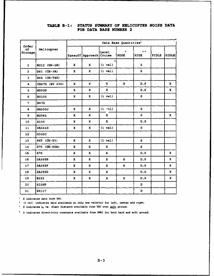
TABLE B-I: STATUS SUMMARY OF HELICOPTER NOISE DATAFOR DATA BASE NUMBER 2
Data Base Quantities,Order
of HelicopterStorage Level 3 3.4
Takeoff Approach Cruise HOGE HIGE FIDLE GIDLE
Ia
1 B212 (UH-IN) X X (1 vel) S
2 S61 (CH-3A) X X (1 vel) S
3 S64 (CH-54B)
4 CH47D (BV 234) X X X S DS X
5 H500D X X X D,S x
6 B0105 X X (1 vel) S
7 B47G
8 SA330J X X (i -,0) S
9 B206L X X X S x
10 A109 X X X D,S
11 SA341G X X (i vel) S
12 H300C
13 S65 (CH-53) X X (1 vel) S
14 S70 (UH-60A) X X X S
15 S76 X X X D,S X
16 SA365N X X X S D,S X
17 SA355F X X X S D,S X
18 SA350D X X X D,S X
19 B222 X X X S D,S X
20 R22HP D
21 BK117 D
X X indicates data from TSC.
* (1 vel) indicates data available at only one velocity for left, center and right.
S indicates L, vs. Slant Distance available from TSC over soft ground.
* D indicates directivity constants available from SWRI for both hard and soft ground.
B-3

C'- r-4 0 r4 %D in IV 4 N M N* .4 %p 0 0% 0o N4 0 qin r4 0 r- CD in 0 " w. D fn 0% Ch a %D W n Z- N m-0 -4 0 %0 in m H4 r- r, en 4 r-4 r, 0 OD in 4'0 0 O
fn In at 0%m in C" r- r- fn N 0% (F% O0 N 0 0 %D W .4rQ1- -0 0 0 r- N IV 0P% 14 M 4W V. CO 4 OD CO N Ln CO C'-
.4C C; N 4 4 0 .4 0 0* 0' 0 0 0 N
- A CID 0 10 N %D w co in 0 %D in 0 a, Go %V m m 0% N0h 0 m4 Ch 0 OD 0 0 (1% 0 0h 0 0% in r- N NM m 0 Vý4) -0 n 0 0% 0 (h in 0 Ch in ON 0 IV q (?% 0 in a 0 10
H4U N C'- N 0 a 0 Ch C'- 0 0% N 0% in N N -0 in r'- 0 0 Nu r- (' N %o 0 w0 o m% vi , 'o N4 v ' N- i4 n CD N .4 CD C-H
N ~~N in0 in N w% 4. mn v4 w 1 0 v" 0ý m C m in0 m~ N* 0- .4 w" ' N H4 in 0h 0% C'- en H N C'- %D Nu 4w It 0% m in M 0O N C" %D .4 r. C" 0 .4 In 0 Ch .4 .4
.4 0 v. 0 M n N r- .4 0 , 10 4 A OD N 0% in Ch H4 n %D
C; '; N ý .4 M M C'- in C; 0 ; N0 0; .4 iC;M 0 i
I I I I I I ? I - - I I I
0 N .4 %D OD 0D 0h w in 0% 0 M%D V0 4 n 0% M 4 N Ni 0 M% in 0 Ch ". v 0% in v m m 0 0 IV 0% v. .4 4 n
oD 0% N in V. r- r- v. I' N N N in in N v C'- in C" Nm 0 IM .4 C'- N n 0D N1 .4 %D %V .4 r- t- %D N M N en .
@1 0. r 0 0q 0 4 CD q 0% 0n % 0 0 M % N 0aen 0 % %D . v 0 o
%4 r OD %0 '0 C'- .4 IV .4 * N fn 0 D (h O . l N .4) e N (n C' 0% IV m 0 v. 03 %0 0% in C" 0% 0% in 0% in %a 0
0 04 r- to 4. v o in %00 NI ND r" iD C r . r n (n Ný %0% 0 %0 .4 M4 0 n 0 . f" 0 N .4 0% 0 0n 0, N N0
0 in r, in r- CD 0 %0 in %D r. Nl in 0 %a Mn (h 0 0 00CD 0 h 0% 0 r- N .4 0h% r C h~0 0 CD q 0 0 0 in q% co .4
4. VN r 0 0 in 0 0% q 0% in 4W in in in 0 m a, 4.0E- N r N r V -0 r 0'-m 0 N C'- N N C'- 0 0% 0% N 0
o 4 0 0 4 %0 0 0- 0 0t 0 0% . 0 .4 M v4 N .4 .4 I r"
0 4 ; C; 0' C; 4ý Iý a" CN
m.I0% 0% r" % 4 0 Ch C'- c N4 in 0 (h .4 H4 N N I. NN01 .4 Nq en 0 0 in r- r'- %D C- 0D r, 0% ý4 in r- 4'n M C'-
N %D NM 0 4r C" at in .4 m 0 .4 r Ch' 0 0 in 0 in %a 0Wf IV N 0D 0 .4 n Ch 0D r4 .4 %0 fn m 0% r'- N 0% 0D C- Itig .4 Mn 0 4 w0 C" 0 N .4 %0 %a N r- IV v. C N in @ -4
; .4 0 ý N ý N ý in* in 4N4 1; 0; 0; . f", 0 4 N ' 0 0mI I I I I I I I I # I I I I I I I1 1
94 C- ýCIA N l a,- 0% n 0D v Ch C" 0 0% m M C"' 0 0D N m %a'(1 N 0 (" 0o .4 0 w0 0 N4 (n '0 N4 M Ct 0% %D IV Ch InN (A 0D .4 Ln .4 V ". Ch 0D '0 4 f" 4 %0 0 v %D .4 In
0 h D 4 '0 % 0 IV .4 m N in 0 '0 N N m .4 v. inin 0% C!- a!n i n N . 4 ' i
1 4 .4 W 44 W 4 w5ww 4 4 4 w 44 w W4.w4 4to 0to0 0 0 0o 0 0d 0 0 to 0 0a 0 0 0 0 0
a. =Iw lE n V
0 z iC) in n in 0a. '
-.4 N4 '0 0 in in I'-.4 0.-4 N rn 0 fn m 0 %D N .4 0
4) N n in -Lo w"N
B-4

APPENDIX C
ERROR MESSAGES AND PROBLEMS
This Appendix presents the error messages produced by HNM Version2.2. Error messages have the same numbers as in the INM tomaintain compatibility. Some messages, however, have been alteredto reflect changes between the HNM and INM. In addition, errormessages concerning INM approach-parameter sets and INM takeoff-modification sets do not exist in the HNM.
C.1 Input Module Error Messages
The following errors can occur while executing the Input module.The errors will appear in reverse video on the last line of thedisplay screen, starting at the first column. Note: INM ErrorsIl-Ill, 114, 117-119, 121, 123, 124, 126-128, 130-138, 140,141-146, 148-159, 161-165, 167-169, 171, 172, 174-184, 186,188-1102 will not occur when using the HNM data entry module; andINM Errors 130, 132, 133, 134, 135, 137, 142, 143, 151, 155, 169,194, 198, and 199 do not exist in the HNM.
I12*FATAL: ABOVE KEYWORD ENDS SETUP SECTION AND NO PADS HAVE BEEN DEFINED.
Cause: No valid helipad definitions were processed.
Correction: Check that keyword "RUNWAYS" was present and recognized.Check that there is at least one helipad defined andthat all definitions area valid.
I13*WARNING: ABOVE KEYWORD HAS OCCURRED MORE THAN ONCE AND MAY ALTERINPUT.
Cause: Since data is entered by keyword, if a keyword isrepeated, the new data replaces the previous data.
Correction: If the keyword is a duplicate, delete the duplicatekeyword and associated data.
I15*WARNING: THESE CHARACTERS NOT PROCESSED. THEY ARE NOT OF TYPEEXPECTED.
Cause: If characters are numeric, alpha characters wereexpected. If characters are alpha, numeric characters
Correction: Remove any extraneous characters. If characters are notextraneous, check that preceding data has been processedproperly. This error may occur when data is expected tofollow a keyword or another keyword is expected tofollow some data.
I16*WARNING: INVALID HELIPAD NAME.
Cause: Helipad name not found.
Correction: Correct helipad name.
C-1

I20*FATAL: TOTAL ERRORS EXCEED 50 OR NUMBER OF ERRORS ON ABOVE CARD
Cause: Too many errors have been detected in the input data.
Correction: Correct all the preceding errors and re-submit the job.
122*FATAL: INPUT MODULE PRODUCED WARNING MESSAGES. PROGRAM TERMINATED.
Cause: At least one input error was detected by the INPUTmodule. Since this error invalidates the user input, nofurther processing is allowed.
Correction: Correct all of the preceding errors.
125*FATAL: ABOVE KEYWORD ENDS AIRCRAFT SECTION AND NO AIRCRAFT WEREDEFINED.
Cause: No valid helicopter definitions were processed.
Correction: Check for a TYPE subsection within the AIRCRAFT section.Make certain that this subsection contains at least onehelicopter definition and that all definitions arevalid.
129*WarninQg: ABOVE NAME IS TOO LONG. IT HAS BEEN TRUNCATED TO 4CHARACTERS.
Cause: A maximum of 4 characters are allowed for the names ofaircraft categories and tracks, and a maximum of 3 forhelipads. The input name or a reference to a helipadexceeds 4 characters.
Correction: Use a unique 3- or 4-character name as required.
139*WARNING: DISTANCE IN Ft CANNOT BE STORED ON DEFINITION FILE. SET TO0.
Cause: After conversion to ft, this distance was too large forthe format in which it must be stored on the definitionfile. Therefore, a value of 0.0 was used for thedistance.
Correction: Enter a distance within the proper range.
147*WARNING: PROFILE DESCRIP. NOT READ. VALUE OF SEGMENTS NOT BETWEEN 3AND 14.
Cause: Within the taxi profile definition, the number ofsegments must be from 3 through 14 for both the approachand takeoff portions of the profile. The takeoffsegments are determined from the beginning of the taxito moving HIGE mode. Approach segments are the movingHIGE mode to the end of the taxi. Since an invalidvalue was entered for the number of segments, the datafor the distances, altitudes, speeds, and thrusts couldnot be processed. If this error occurs for an approachprofile, any mode name will be read as a keyword and theprogram will go back to a level 1 search on keywords.
Correction: Make certain that the profile has between 3 and 14segments and that the value following the keyword"SEGMENTS" is that number of segments.
C-2

160*WARNING: ABOVE KEYWORDS ENDS TRACK DEFINITION BUT NO SEGMENTS WEREDEFINED,
Cause: Within a track definition, there must be at least onesegment. None were found fcr this track.
Correction: Enter at least one segment description for the track.
I66*WARNING: ABOVE HELIPAD NAME NOT FOUND IN XREF. ID SET TO 0.
Cause: within a track definition, a helipad was referenced butwas not found in the cross reference table.
Correction: Verify that the name is spelled correctly and wasdefined in the SETUP section. This message will alsoappear if the cross reference table was filled beforethis helipad was defined.
170*WARNING: NO VALID OPERATIONS DEFINED IN LAST OPERATIONS SECTION.
Cause: Within a TAKEOFFS, LANDINGS, or TAXIS section, at leastone valid operation must be defined. None was definedfor the section preceding this keyword.
Correction: Correct any invalid operations within the section andadd operations if none were present.
173*WARNING: ABOVE KEYWORD ENDS OPERATION DEFINITION BUT NO D. E, N VALUESGIVEN.
Cause: Within TAKEOFFS, LANDINGS, and TAXIS, operations mustinclude the number of flights by day ("D") and night("N") with at least one of these being explicitlydefined. In this operation, no flights were specified.
Correction: Check for missing or misspelled keywords (at least oneof the keywords "D" or "N") and for a valid number offlights for that period of time. At least one timeperiod must have a non-zero number of flights.
I85*WARNING: ABOVE NAME IS DUPLICATE CONTOUR NAME OR 20 CONTOURS ALREADYSAVED.
Cause: Within the PROCESS section, contours are saved andreferenced by their names. A duplicate name has beenencountered or more than 20 contours were specified tobe saved.
Correction: Make the saved contour names unique and limit the totalto 20 contours.
I87*WARNING: RETRIEVE COMMAND BEFORE ABOVE KEYWORD REQUESTED NO REPORTS.
Cause: A RETRIEVE command must call for some type of report.For this RETRIEVE, the user has suppressed the defaultREPORT option with a NOREPORT command but did not selecta PLOT report.
Correction: Add requests for the types of reports desired.
C-3

C.2 Flight Module Error Messages
The following errors can occur while executing the Flight module.The errors will appear in reverse video on the last line of thedisplay screen, starting at the first column. Note: INM ErrorsF2, F3, F5, F6, FS, and F9 will not occur when using the HNM dataentry modules; and INM Errors F3, F8, and F9 do not exist in theHNM.
Fl*FATAL: PAD XXXX TRACK: YYYY PROFILE: ZZZZZZ TOO MANY SEGMENTS. ARRAYBOUNDS EXCEEDED.
cause: The number of flight path segments generated for thisflight exceeds 200.
Correction: Verify the helipad, track, and profile definitions forthis flight. If all are correct, then simplify theflight path definition.
F4*FATAL: PAD XXX TRACK: YYYY PROFILE: ZZZZZZ TRACK SEGMENT OUT OF RANGE.
Cause: The actual number of track segments does not equal thetrack segment counter.
Correction: Correct the track in error.
F7*FATAL: PAD XXXX TRACK: YYYY PROFILE: ZZZZZZ CHANGE IN HEIGHT GREATERTHAN SEGMENT LENGTH.
Cause: A flight path segment has been generated where theaircraft's change in altitude is greater than the actuallength of the flight segment.
Correction: Verify the track and profile definitions for thisflight.
C.3 Computation Module Error Messages
The following errors can occur while executing the HNM Computationmodule. The errors will appear in reverse video on the last lineof the display screen, starting at the first column. INM Errors C1and C2 will not occur when using the HNM data entry modules.
C3*FATAL: NO CONTOUR LEVEL SELECTED
Cause: No contour level values were found on the processingtemplate.
Correction: Supply the missing noise contour level(s).
C4*FATAL: TOLERANCE CANNOT BE ZERO
Cause: The user has incorrectly defined the recursivelysubdivided grid window.
Correction: Correct the window coordinates.
C-4

C.4 Report Generator Module Error Messages
The following errors can occur while executing the HNM ReportGenerator Module. The errors will appear in reverse video on thelast line of the display screen, starting at the first column.
RGI*FATAL: NO DETAILED GRID REPORT PRODUCED. ERROR IN COMPUTATION MODULE.
Cause: The COMPUTATION module did not run successfully andconsequently did not produce the CONTRIBUTIONS file fromwhich the Detailed Grid Analysis Report is produced.
Correction: Correct the error previously reported by the COMPUTATIONmodule.
RG2*FATAL: NO STANDARD GRID REPORT PRODUCED. ERROR IN COMPUTATION MODULE.
Cause: The COMPUTATION module did not run successfully andconsequently did not produce the regular GRID file fromwhich the Standard Grid Analysis Report is produced.
Correction: Correct the error previously reported by the COMPUTATION
module.
RG3*FATAL: NO CONTOUR REPORT PRODUCED. ERROR IN COMPUTATION MODULE.
Cause: The COMPUTATION module did not run successfully andconsequently did not produce the recursively subdividedGRID file from which supplies data for the ContourAnalysis Report.
Correction: Correct the error previously reported by the COMPUTATIONmodule.
C.5 Contour Module Error Messages
The following errors can occur while executing the HNM ContourModule. The errors will appear in reverse video on the last lineof the display screen, starting at the first column.
CNl*FATAL: CONTOUR NAME XXXXXX DOES NOT EXIST
Cause: The Grid File does not contain the contour definitionname.
Correction: Case 1 -- If this message occurs when a RETRIEVE commandis being processed, then an invalid CONTOUR name wasused to retrieve from the given old Grid File. Correctthe name or select the appropriate old Grid File.
Case 2 -- If this message occurs when a CONTOUR commandis being processed, there was a previous error in theCOMPUTATION module and no Grid File was created for thiscontour name. Correct the error reported by theCOMPUTATION module.
CN2*WARNING: XXXX YY.YY CONTOUR AND AREA MAY BE INCOMPLETE
Cause: The contour with metric name = XXXX and level = YY.YYwas determined to not be within the range of levelsinput to the COMPUTATION module. Therefore, the contourmay not be accurate.
C-5

Correction: If an accurate contour for this level is desired, then
resubmit the job to invoke the COMPUTATION module.
CN3*WARNING: XXXX YYY.YY CONTOUR DOES NOT EXIST
Cause: All noise values computed by the COMPUTATION module formetric XXXX are less than contour level a YY.YY.
Correction: No action is required as long as the user has input areasonable contour level.
C6 Plot Module Error Meusages
The following errors can occur while executing the HNM Plot Module.The errors will appear in reverse video on the last line of thedisplay screen, starting at the first column.
P1*FATAL: NO PLOT TAPE CREATED DUE TO CONTOUR MODULE ERROR
Cause: It is not possible to plot the requested contours due toa previously encountered error in the CONTOUR module.
Correction: Correct the CONTOUR module processing error.
P2*WARINg: NO PLOT FOR CONTOUR LEVEL NUMBER - XX
Cause: No contour for this noise level exists.
Correction: As long as the contour value input to the COMPUTATIONmodule was correct, no action is required.
C-6

APPENDIX D
EiM REQUEST FORM
This Appendix contains a copy of the request form for HNM Version2.2.
D-1

REQUEST FORMHELIPORT NOISE MODEL (HNM)
VERSION 2.2
DATE
LAST NAME FIRST NAME
COMPANY
DIVISION
STREET ADDRESS
U.S ONLY:
CITY STATE ZIP CODE + 4
FOREIGN ONLY:
POSTAL CODES & CITY
COUNTRY
U.S. & FOREIGN:
PHONE FAX
M VZRISON 2.2, disk size Ichoose one): 10 5-1/4" 0 3-1/28
To receive HNM Version 2.2, mail this form and your check or money order for $50 payable to OU.5.Troasury to:
Donna G. WarrenFederal Aviation AdministrationAEE- 120800 Independence Ave., SWWashington, DC 20591
*****jNP0ORTA=*t * **
Due to the expected demand for this •IM release, all orders will be handled by regular mail. FAAwill not accept phone orders, PAZ orders, nor process special or express deliveries of any kind.
ABE BULLETIN BOARD (BBS)
The Office of Environment and Energy (ACE) has available an electronic bulletin board. This bulletinboard is available to all registered HNM users. To become a registered BBS user, check the box below. Bychecking the box you will receive the BBS phone number and User's Manual. To connect to this board users musthave a modem and a communications software package setup as follows: ANSI Terminal Emulation, 8 Data Bits,No Parity, 1 stop Bit, and 1200, 2400, or 9600 BAUD.
0 Yes, I would like to become a registered AEE BBS user.
D-2


![1093 gilchrist[2]](https://static.fdocuments.net/doc/165x107/559116061a28ab0b168b4730/1093-gilchrist2.jpg)