Research Report - DTIC:hough the BGM-109G integrated high technology and sound operating icepts, the...
87
~ IIII~ ~I ~III ~III III __________________________________________________________ i AD-A258 351 S~AIR WAR COLLEGE Research Report UNITED STATES AIR FORCE GROUND LAUNCHED CRUISE MISSILES: A STUDY IN TECHNOLOGY, CONCEPTS, AND DETERRENCE AIR FORCE HISTORICAL FOUNDATION AWARD RANDALL L. LANNING LIEUTENANT COLONEL, USAF 1992 ft A.. " 2 068 92-32711 Air University Approv For Pubc United States Air Force RctAesc Distribution Unlimited Maxwell Air Force Base, Alabama
Transcript of Research Report - DTIC:hough the BGM-109G integrated high technology and sound operating icepts, the...

~ III I~ ~I ~III ~III III __________________________________________________________ iAD-A258 351
S~AIR WAR COLLEGE
Research Report
UNITED STATES AIR FORCE GROUND LAUNCHED CRUISE MISSILES:
A STUDY IN TECHNOLOGY, CONCEPTS, AND DETERRENCE
AIR FORCE HISTORICAL FOUNDATION AWARD
RANDALL L. LANNING
LIEUTENANT COLONEL, USAF
1992
ft A..
" 2 068 92-32711
Air University Approv For PubcUnited States Air Force RctAesc Distribution UnlimitedMaxwell Air Force Base, Alabama

AIR WAR COLLEGE
AIR UNIVERSITY
"UNITED STATES AIR FORCE GROUND LAUNCHED CRUISE MISSILES:
A STUDY IN TECHNOLOGY, CONCEPTS, AND DETERRENCE-
by
Randall L. LanningLt Colonel, USAF
A RESEARCH PAPER SUBMITTED TO THE FACULTY
IN
FULFILLMENT OF THE CURRICULUM
REQUIREMENT
Advisor: Col James H. Slagle
MAXWELL AIR FORCE BASE, ALABAMA
15 April 1992
DISCLAIMER
This study represents the views of the author and does
not necessarily reflect the official opinion of the Air War
College or the Department of the Air Force. In accordance
with Air Force Regulation 110-8, it is not copyrighted but
is the property of the United States government.
Loan copies of this document may be obtained through
the interlibrary loan desk of the Air University Library,
Maxwell Air Force Base, Alabama 36112-5564 (telephone (205)
953-7223 or DSN 493-7223).
Accesion For
NTIS CRA&IDTIC TABUnannouncedJustification
B y .................. ........................
By------- -
Distribution I
Availability Codes
Avail and /orDist Special
ii
ABSTRACT
rITLE: "United States Air Force Ground Launched Cruise Missiles:
A Study in Technology, Concepts and Deterrence"
WTHOR: Randall L. Lanning, Lieutenant Colonel, USAF
Although generally neglected by historians, USAF Ground
Launched Cruise Missiles (GLCM) have made important contributions
to US national security. The paper begins with a brief description
of the German V-1, the first true operational GLCM. The balance
of the paper traces the lineage of the three tactical, theater-
based GLCMs that served with the US Air Force: The Martin TM-61
"Matador," the Martin TM-76 "Mace," and the General Dynamics BGM-109G
"Gryphon." Areas for a comparison and contrast assessment of
these systems include the strategic setting, technological
description (missile and support equipment), concepts of operation,
operational history, phase out, and contributions to deterrence.
Appendices, maps, figures, and photographs support the main body.
The paper concludes that the first two systems (TM-61 and TM-76)
possessed neither the technological sophistication nor sounu concept
of operations to make them truly effective weapons. Both
deficiencies were rectified in the BGM-109G system. However,
with conclusion of the Intermediate Range Nuclear Forces Treaty
in December, 1987, this class of missiles will probably never
be deployed again. Arms control initiatives removed them just
when technology and sound operating concepts enabled the GLCM
to be a potent deterrent.
iii

BIOGRAPHICAL SKETCH
Lieutenant Colonel Randall L. Lanning (M.A., European History,
:entral Missouri State University) retains a long term interest
Ln military history with an emphasis on weapons technology. This
Lnterest was focused on cruise missiles when he was assigned to
the Initial Operational Test and Evaluation Team for the BGM-109G
3round Launched Cruise Missile (GLCM) in August, 1980. In December,
L982, he was sent to RAF Greenham Common UK as part of the initial
:adre of the first operational unit, the 501st Tactical Missile
Ring (TMW). While working in the Operations Plans Division, he
was instrumental in the development of the first unit-level GLCM
war plan and Emergency Actions File, the plan for transitioning
the wing from peace to war.
In July, 1985, he was sent to the Directorate of GLCM Operations
at Headquarters, United States Air Forces, Europe (USAFE). During
ais tenure, he was the USAFE GLCM operations point of contact for
the beddown of the 303rd TMW at RAF Molesworth UK, the USAFE GLCM
war plan, and the Intermediate Range Nuclear Forces Treaty, signed
in December, 1987.
In 1988, he was transferred to the Air Staff where he servcd
as the political-military affairs officer for the UK and Scandinavia,
ind in 1989, became Political-Military Advisor to the Deputy Under
3ecretary of the Air Force for International Affairs.
Lt Col Lanning has earned the command missile badge, with time
Ln the GLCM and the Minuteman II weapon systems. He is a 1992 graduate
Af the Air War College.
iv
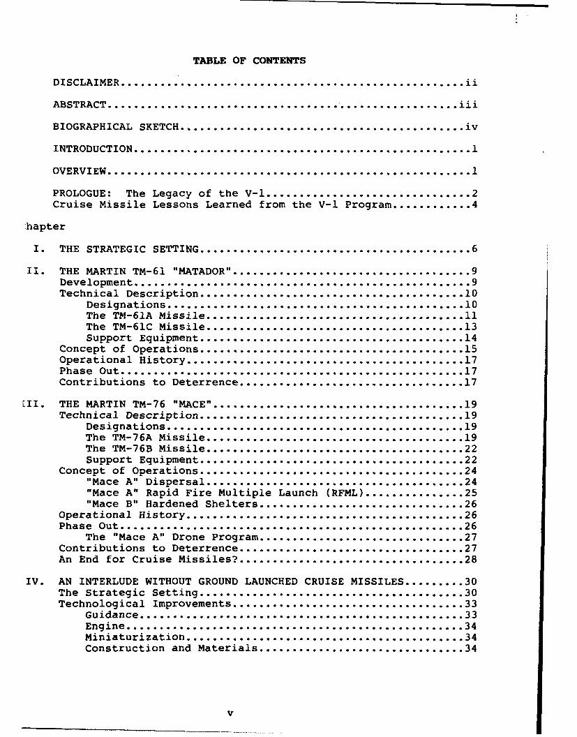
TABLE OF CONTENTS
DISCLAIMER............................................ .......ii
ABSTRACT..................... ...... ....o- ... .. ... o... ... .........111
BIOGRAPHICAL SKETCH ..... o.... oooooos ..... o.... ..... ,i............v
INTODCTIN..............................................................
OVERVIEW............................... oo.o.o.o.......... .. o.......
PROLOGUE: The Legacy of the V- ....... o...... o.................2
Cruise Missile Lessons Learned from the V-1 Program..... ........ 4
'hapter
Io THE STRATEGIC SETTING.......................... o - ...... .. ....o_ 6
II. THE MARTIN TM-61 "MATADOR'..........................o.....--owo 9Development.............................. ......... ... .... ..o-....-9Technical Description.....o...... oo ..................... .......10
Designations................... ............................. 10The TM-61A M~issile.... ..................................... 11The TM-61C Missile..........................oo -..... 13Support Eupet.........................14
Concept of operations.......... ...........................15Operational History....-!.-........................... o........... 17Phase Out........... ......................................... .... 17Contributions to Deterrence ..... oo.... oo....... o...... o............17
II.o THE M4ARTIN TM-76 "MACE"............ ............o- ...... ...o-o.....19'Technical. Description.............. ... -..... o ...-....... o-..............19
Designations... ......................................... o ..... o o.... 19The TM-76A Missile.,....... ...................... -..... 19The TM-76B Missile ... o................................. o.. .. o.........22
Support Equipment........... ........ ...o- ..... o ...... ........22Concept of Operations................... ......... ...... .........24
"Mhuace A" Dispersal ......- - o........... o... o...............24"Mace A" Rapid Fire Multiple Launch (RFML) ............... o.25"Mace B" Hardened Shelters.................... ........oo...-26
Operational History... ....................... .......... ....oo- -. 26Phase Out... ........................ o................... .....26
The "Mace A" Drone Porm......................27Contributions to Deterrence.......................................2An End forCruise Missiles?..........................................o~oo..28
IV. AN INTERLUDE WITHOUT GROUND LAUNCHED CRUISE MISSILES..........30The Strategic Setting...........................................3Technological Improvements....... ... -.... -o.................33
Guidance...........................oo......o........o~~oo o-oo33Engine... .o...........................................34Miniaturization............................................ o- oo o o ...... 34Construction and Materials........... ......................... 34
V
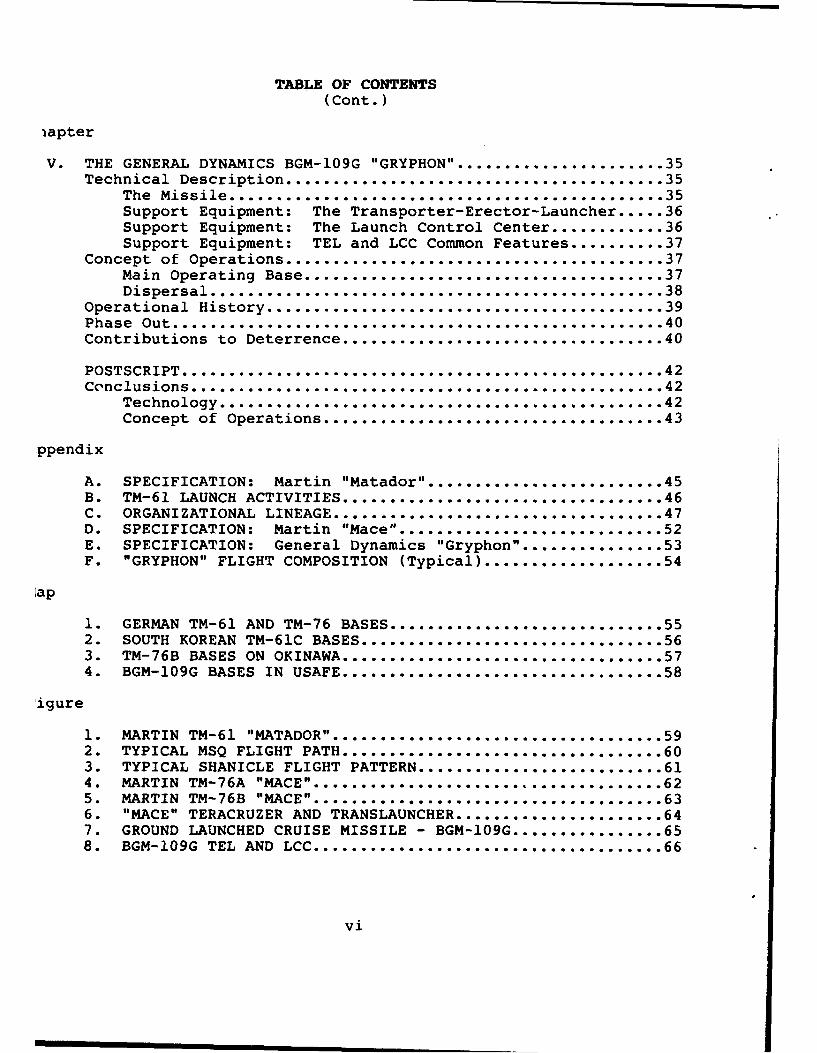
TABLE OF CONTENTS
(Cont.)
iapter
V. THE GENERAL DYNAMICS BGM-109G "GRYPHON" ........................ 35Technical Description ........................................ 35
The Missile .............................................. 35Support Equipment: The Transporter-Erector-Launcher ..... 36Support Equipment: The Launch Control Center ............ 36Support Equipment: TEL and LCC Common Features .......... 37
Concept of Operations ........................................ 37Main Operating Base ...................................... 37Dispersal ................................................ 38
Operational History .......................................... 39Phase Out .................................................... 40Contributions to Deterrence .................................. 40
POSTSCRIPT ................................................... 42Conclusions.................... ..... ........... ........ .... 42
Technology..................................................... 42Concept of Operations................................... 43
ppendix
A. SPECIFICATION: Martin "Matador".......... ............. 45B. TM-61 LAUNCH ACTIVITIES.................. .................. 46C. ORGANIZATIONAL LINEAGE... ........................ 47D. SPECIFICATION: Martin "Mace"......... ............... 52E. SPECIFICATION: General Dynamics "Gryphon ............... 53F. "GRYPHON" FLIGHT COMPOSITION (Typical)...... ............ 54
lap
1. GERMAN TM-61 AND TM-76 BASES..... ................ 552. SOUTH KOREAN TM-61C BASES ............................. 563. TM-76B BASES ON OKINAWA..... ............ ......... 574. BGM-109G BASES IN USAFE ... ................. 58
'igure
1 . MARTIN TM-61 "MATADOR" .................. ...... .... 592. TYPICAL MSQ FLIGHT PATH. ........... ... o ......... . .... 603. TYPICAL SHANICLE FLIGHT PATTERN............................. 614o MARTIN TM-76A "MACE" ..... . ..........................625. MARTooIN ToM-76B .... ............ooo .. o................oo636. "MACE"TERACRUZERANDTRANSLAUNCHER..................... 647. GROUND LAUNCHED CRUISE MISSILE - BGM-109G ................ 658. BGM-109G TEL AND LCC ............................. 66
vi

TABLE OF CONTENTS(Cont.)
tograph
1. TM-61 MISSILE LAUNCH ..................................... 672. TM-61 ZERO-LENGTH LAUNCHER ............................... 683. TM-61 ASSEMBLY PROCEDURES - WARHEAD MATING ............... 694. TM-61 ASSEMBLY PROCEDURES - RATO LOADING .................. 705. TM-76A MOUNTED ON TRANSLAUNCHER .......................... 716. MM-I PRIME MOVER FOR THE TM-76A .......................... 727. RAPID FIRE MULTIPLE LAUNCH FACILITY ...................... 738. TM-76B LAUNCH FROM HARDENED SHELTER ...................... 74
LIST OF REFERENCES ........................................... 75
GLOSSARY ..................................................... .78
vii
UNITED STATES AIR FORCE. GROUND LAUNCHED CRUISE MISSILES:
A STUDY IN TECHNOLOGY, CONCEPTS, AND DETERRENCE
Introduction
Science fiction writers in the early 20th Century must
re been infatuated with the idea of unmanned airborne "robot"
ibers that could fly to distant targets and rain a devastating
7load upon helpless populations. The Second World War saw this
icept become reality, albeit in rudimentary form. Today, when
! average citizen thinks about unmanned delivery systems, the
Llistic missile comes to mind first. But the winged, air breathing
Uise missile, which preceded ballistic missiles, has made both
ýhnological and deterrent contributions to US security. Even
cruise missiles have generally been neglected by historians.
Overview
The purpose of this paper is to trace the lineage of three
tactical, theater-based Ground Launched Cruise Missiles (GLCM):
SMartin TM-61 "Matador," the Martin TM-76 "Mace," and the General
iamics BGM-109G "Gryphon." Following a prologue introduction
the first operational GLCM, the German V-1, each system will
discussed in terms of the strategic setting, technology, concept
operations, operational history, phase out, and contributions
deterrence. This study will show that technology and operating
icepts were unable to blend effectively in the two earlier systems.
:hough the BGM-109G integrated high technology and sound operating
icepts, the Intermediate Range Nuclear Force (INF) Treaty (signed
)ecember, 1987) eliminated this class of missiles. Conclusions
this work will provide a detailed contrast and comparison.
- 1 -
PROLOGUE
The Legacy of the V-I
The German V-I was the first "guided" (by gyro autopilot)
ile to be used in large numbers, and will be remembered as
of the most destructive and unique weapon systems in history.
t flown in December, 1942, it was known by several designations
41). Technically, it was known as the Feisler Fi-103, but
most common terms were V-i (V for Vergeltungswaffe or vengeance
on), and simply "Buzz Bomb" and "Doodlebug." Regardless of
gnation, the V-I caused far more damage than its well known
.er, the V-2 ballistic missile.
The V-1 was essentially an unmanned aircraft (17 foot wing
* and 26 foot length), powered by an Argus 109-014 pulsejet
.ne. It carried a 1,876 pound (lb) warhead nearly 150 miles
, speed of 400 miles per hour (mph) (11:46). Since the pulsejet
.ne needed a minimum speed of 200 mph to engage, launch was
!cted using a 180 foot ramp and catapult to rapidly gain speed.
.ddition, 1600 were air launched by HE-I11H mother aircraft
urther extend the range. Regardless of launch mode, after
Liles of flight, a small propeller in the nose armed the warhead.
andard gyro autopilot was used as guidance, and terminal dive
initiated ky fuel starvation. Londoners therefore knew that
ong as they heard the distinctive pulsejet, they were safe.
Of the nearly 30,000 V-is produced, Flak Regiment 155 launched
92 against London. A total of 2,419 actually hit the city,
ing 6,184 people and injuring another 17,981 (33:60). Later
he war, continental targets were also hit, with 7,400 V-is
- 2 -
ted against Antwerp, Netherlands and Liege, Belgium (33:60).
The British used a four-tiered defense system against the
The first line of defense was bombing the launch sites (88
rmed sites by December, 1943) and the factories where the
were built. Roughly 67% of those V-is actually launched
downed by the remaining defenses. Allied fighters were used
tercept the V-is, but due to the missile's speed, few were
enough to catch it. The British Supermarine "Spitfire" XIV,
r "Tempest" V, and DeHavilland "Mosquito" together with the
can P-51 "Mustang" were the prime interceptors. The Gloster
or" I, Britain's first operational jet, was also used on
ntercept missions. Gunfire was often used, but the jet exhaust
the V-I could cause damage to the interceptor. An alternate
d was to ease up along side the V-i, slipping a wing under
issile's wing, and flipping it over to throw off the gyro
ilot. This method, though unconventional, was less dangerous,
equired more flying skill. The last two lines of defense
antiaircraft guns and barrage balloons. However, neither
as effective as bombing and aerial interception.
Following the war, both the US Army Air Corps/Air Force
avy experimented with the V-I under the designations JB-2
Loon" respectively. The Navy saw potential for launching
missiles from submarines, and 64 such tests were conducted
3). A total of 1,385 JB-2/"Loons" were delivered, but interests
re advanced cruise missiles ("Matador" and "Regulus"
ctively) by both Services precluded widescale procurement
eployment.
- 3-
ie Missile Lessons Learned from the V-I Program
The V-I proved that the cruise missile could be a useful,
effective weapon. An Allied study after World War II concluded
F-1 production/operating cost-to-inflicted damage ratio in
)llars was 1:3 (33:61). The system had some distinct, inherent
itages. It was a relatively inexpensive weapon that did not
Lre use of strategic materials and could be used in mass.
is a true "pilot saver" that could be launched in all typ.s
ýather, day or night. Once airborne, the missile was difficult
)ot and attack because of its relatively small size, high
1, and low altitude flight path. The V-I also had few parts
were critically vulnerable to attack.
Like all weapon systems, the V-I also had some distinct
tations. For the most part, it was launched from fixed (and
afore vulnerable) launch sites. Unlike the V-2, V-1 ground
:hers were never mobile, or even movable. Once aloft, the
ile flew a predictable flight path with a constant course
speed. Knowing this, the Allies could effectively plan
rdingly. Finally, the missile had extremely poor accuracy,
a severely limited its effectiveness as a precision bombardment
:n. Its primary impact therefore was one psychological warfare
terror). A parallel can be drawn between the V-1 in World
HI and the Iraqi "Scud-B" during Operation DESERT STORM in
regard.
After the war, further work on cruise missiles was curtailed
three primary reasons. First, because of Allied defenses
ast the V-i, postwar opinion regarding cruise missiles tended
- 4 -
to downplay their effectiveness. It was assessed that these early
cruise missiles were too vulnerable to countermeasures. Second,
with rapid demobilization after the Second World War, funding
was not readily available for in-depth development. The Martin
"Matador" discussed in Chapter 2, was one of the few cruise missile
systems to escape cancellation during the postwar period.
Finally, with the Air Force's proud tradition of manned
aircraft, there was probably an understandable resistance by senior
Air Force leaders to deploy a pilotless or remote control weapon.
From the earliest days of combat aviation, there has been a
justifiable reliance on "the man in the cockpit." While the cruise
missile offers the military planner flexibility and many other
advantages, its use and cost have been a concern of Air Force
leaders because it removes the human element from immediate combat.
In summary, the V-1 proved to be a remarkable technical
achievement. The balance sheet showed that it was a cost effective
weapon for the Germans; it had to be in the later war years.
It was advanced technically, economically, and tactically. This
assessment set the stage for development of the Air Force's first
surface-to-surface guided missile, the Martin TM-61 "Matador."
-5-
CHAPTER I
THE STRATEGIC SETTING
At the end of the Second World War, the common ties that
held the Grand Alliance together dissipated rapidly. The Soviet
Union under Josef Stalin remained fearful of foreign invasion
'' and came to depend on the Eastern European buffer to ensure their
national security. While working with Stalin was acceptable
to President Roosevelt during the war years, President Truman
viewed Soviet adventures in Eastern Europe as attempts to expand
Communism. In 1947, when Communist inroads appeared likely in
Greece and Turkey, the President established the Truman Doctrine.
This policy stated that the United States would support any
non-Communist government attempting to resist subjugation by
the Soviets. Relations between the US and USSR were further
distanced when the Soviets declined assistance under the Marshal
Plan of 1948. The Berlin blockade and formation of NATO in 1948
and 1949 respectively lead to further entrenchment on both sides.
When Mao Tse Tung seized power in China in 1949 and North Korea
attacked the South in 1950, President Truman's "Containment"
strategy was expanded to the global realm. Throughout this period
(1945-1953), the United States had a virtual monopoly on atomic
weapons, although we did not have many of them. The first Soviet
atomic bomb was exploded in 1949. President Truman's strategy
of "Containment" restored the balance of power in Europe and
set the tone for future relations between the US and Soviet Union.
When President Eisenhower assumed office in 1953, he realized
that containing Communism would be a very expensive venture over
- 6 -
the "long haul." Given that. the US had clear nuclear superiority,
then Secretary of State John Foster Dulles announced the nuclear
strategy called "Massive Retaliation" in January, 1954. This
policy stated that the United States would retaliate at times
and places, and with means of our own choosing. "Massive
Retaliation" exemplified "brinkmanship," in that the Soviets
would have to carefully calculate how aggressive they could be
without bringing a massive nuclear strike down upon themselves.
It also took the initiative away from the Soviets, an advantage
they had enjoyed under the previous "Containment" strategy.
US military response to Soviet aggression would no longer
necessarily be limited to the immediate conflict area.
Concurrently, President Eisenhower advocated five major
tenants of his "New Look" umbrella defense strategy, which embraced
"Massive Retaliation:"
- The United States would never start a war.
- US military forces would be used to deter conflict.
- Modern (nuclear) weapons would be employed.
- Alliances would be an integral part of US defense strategy.
- US national security depended on both military and economic
capability.
It is interesting to note that these five concepts have essentially
endured to this day. President Eisenhower's last point on economic
capability was key. He planned to use overwhelming US nuclear
superiority as a less expensive alternative deterrent to
conventional forces. These non-nuclear forces would continue
to play a "tripwire" role overseas to signal Soviet aggression.
- 7 -
Clearly, nuclear superiority from 1953 to 1961 allowed "Massive
Retaliation" to succeed. Even so, "Flexible Retaliation" may
have been a more appropriate term, because there were few scenarios
(attack on the US or Western Europe) where the US would have
massively retaliated. Although the US was comfortably secure
in its nuclear superiority during this period, the launch of
the world's first artificial satellite, Sputnik, by the Soviets
in October, 1957, contributed to fears of a possible missile
and bomber gap. We know now this was only a perceived threat.
By 1954, the Korean War was over and the Soviets had tested
their first thermonuclear bomb. Although the surface-to-surface
missile (SSM) was not used in Korea, great interest remained
in targeting Soviet and Chinese military forces, rather than
cities (counterforce rather than countervalue targeting). Defense
planners recommended development of an entire family of missiles
to support these objectives in the immediate postwar period.
Examples include the Army's "Redstone", the Navy's "Regulus I
and II," and the Air Force's "Snark" and "Matador" (4:27). These
missiles together with a modern bomber force offered diverse
capabilities for US planners against enemy theater forces, as
well as their industrial bases. Even so, the missile had not
been fully accepted into strategic force planning due to the
new technology involved and the varied opinions of V-1 effectiveness
during the Second World War.
-8-

CHAPTER II
THE MARTIN TM-61 =MATADORu
Development
Although funds were limited after World War Two, the success
achieved by the Germans with their V-I spurred similar cruise
missile development in the United States. As noted above, the
American versions of the V-I (JB-2 and "Loon") lead directly to
development of the first US-designed cruise missiles, the Navy's
"Regulus I" and the Air Force's "Matador." The Army was essentially
uninvolved with these types of programs due to a ruling issued
by Secretary of Defense Charles F. Wilson on 26 Nov 56. His guidance
stated that Army weapons used for tactical support would be limited
to a range of 200 miles (23:112).
In 1946, the Glenn L. Martin Company was awarded $1.8 million
to begin development on what was then known as the SSM (presumably
for surface-to-surface missile) (7:1850). With this contract,
the Air Force expressed a need for unmanned "pilotless bombers"
to supplement conventional aircraft. Planners saw cruise missiles
as an effective means to deliver a heavy offensive load at reasonable
cost, since the vehicle could be built for a one way trip, and
avoid designs that needed to accommodate landing stress (17:205).
The Air Force requirement called for a "pilotless bomber" with
a range between 175 and 200 miles at speeds in the 600 miles per
hour (mph) range (33:108). The missile was to be ground launched,
although air delivery was studied. The first XSSM flight occurred
on 19 Jan 49. Concurrently with 10 dynamically similar models,
Martin built 15 XSSM experimental missiles from readily available
-9-
components, modified as necessary to get a missile into the air
as quickly as possible. The aerodynamic shape of the missile
was, in fact, similar to that of the Martin XB-51, a three-engined,
two-place bomber that never entered production (8:300). Testing
of these XSSM's continued at Holloman AFB, New Mexico, throughout
1949 and 1950. During design and test flights, the XSSM program
survived several defense cuts, until the outbreak of the Korean
conflict in June, 1950. Experiences during the Korean conflict
emphasized the need for a tactical cruise missile for bombardment
at medium and long ranges, and SSM development proceeded with
top priority. During this time, another key element that made
the SSM attractive to the Air Force was Martin's zero-length launcher
(ZEL). The ZEL allowed launch from a towed trailer using a rocket
assisted take off (RATO) booster, eliminating the need for the
long catapult rails associated with ground launch of the V-1.
This ZEL, sustainer engine, and RATO combination accelerated the
SSM from 0 to 200 mph in less than two seconds, allowing for takeoff
in a very short distance (14:5).
The SSM evolved into the B-61 (the "B" designation retained
due to its role as a pilotless bomber) to become the first
operational US surface-to-surface missile, with deployments beginning
in March, 1954 in Germany. It was the first cruise missile since
the V-1 to enter service.
Technical Description
Designations
The "Matador" went through several designations throughout
its operational life. As noted above, it was known as the XSSM,
- 10 -

and then the SSM during testing. Upon initial deployment, it
was known as the B-61 until June, 1955 when it was redesignated
TM-61 (Tactical Missile). The TM-61 was developed in three versions,
models A, B, and C. The TM-61A and C remained "Matador" and are
discussed below in this chapter. The TM-61B was such a dramatic
departure from the TM-61A, that it was given an entirely new
designation, the TM-76 "Mace," discussed in the next chapter.
In 1963, the "Matador" was again redesignated as MGM-l, though
by that time it was completely phased out of operational service.
The TM-61A Missile
Appendix A contains the specification for the TM-61 missile.
Figure and Photograph 1 provide illustrations. The SSM closely
resembled the TM-61; the major difference was in wing location.
The SSM had a mid-body wing, while the TM-61 featured a shoulder-
mounted wing.
The TM-61 was in the truest sense of the word a pilotless
airplane. Composed of all-metal sandwich construction, its airframe
was designed for one flight, and therefore more lightly stressed
than a manned aircraft. The inner layer was light alloy with
a honeycomb metal foil filler under a thick metal outer skin,
bonded together with a thermo-setting resin (8:302). The wings,
fin, and tailplane were solid except for control runs and a flux-
gate compass in the port wingtip.
The TM-61 series had the capability to carry either a
conventional or nuclear warhead. The nuclear warhead used was
the Mark 5, America's first lightweight nuclear weapon. Its
fissionable material was kept separate from the weapon in a capsule,
- 11 -
and inserted before launch. Providing a yield of 40 to 50 kilotons,
Lts nuclear punch was not a significant improvement over the bombs
Iropped on Japan at the close of World War II (10:82). An airburst
deapon only, it was designed for high altitude internal carriage,
and most effective against soft targets. Other carriers of this
weapon included the B-29, B-36, B-45, B-47, B-50, B-52, and "Regulus
I" cruise missile.
The sustainer powerplant was the Allison J-33 A-37 centrifugal
turbojet engine, the same used for both the P-80 and T-33. Although
rather unspectacular in performance, it was very reliable. This
was a "short life" version of the engine, designed for only 10
hours of operation (33:109).
The RATO booster weighed 2000 lbs, 700 of which was picric
nitrate solid rocket fuel. Upon ignition, the RATO unit produced
up to 57,000 lbs of thrust for 2.3 seconds, rapidly accelerating
the missile to a speed of 200 mph (8:303). The booster was attached
only by a screw jack on the launcher and forward facing open hooks
on the missile. It was held in place by thrust, and when the
booster burnt out, it simply fell off.
Upon launch, the ground controller had to take control
of the missile immediately after booster separation. At this
time, the missile automatically transitioned to level flight
at booster separation. Its flight path included four phases:
launch, climb, cruise, and terminal dive to burst altitude (28:1),
under continual ground radio control.
The guidance used in the TM-61A employed technology derived
from World War II and Korea all weather bombing systems used to
- 12 -
direct fighter-bomber strikes on enemy targets at night or in
overcast conditions. It was a manually controlled ground radio
command guidance system known as MARC (Manual Airborne Radio
Control). It used an AN/MSQ-I mobile ground radar set and an
AN/APW-IIA airborne radar assembly (12:129). This system was
line-of-sight only, and required ground based radio operators
to be posted on remote mountain tops between the missile launch
point and the target. For German-based units, the 601st Tactical
Control Wing performed this function. These operators were really
remote pilots, who acquired the TM-61A immediately after launch
and guided it to the assigned target. Remote commands included
course changes, warhead arming, and terminal dive. These commands
were manually "beeped" to the autopilot and warhead using the
APW-l1 transponder in the missile. Because this guidance was
line-of-sight, it had inherent drawbacks. It limited the range
to approximately 200 miles, even though the fuel capacity permitted
a longer flight (up to 650 miles). It also had an increased
vulnerability to air interception and was subject to jamming.
The ground radio direction sites were themselves vulnerable to
attack and destruction (14:6). Figure 2 illustrates the MARC
concept.
The TM-61C Missile
For all practical purposes, the TM-61A and TM-61C were
externally identical. Internally, the only major difference was
the guidance system used. As noted above, the MARC system had
limitations. These were partially rectified by the SHANICLE (Short
Range Navigation Vehicle) system introduced in the TM-61C. This
- 13 -

stem, similar to LORAN, employed four ground based transmitters
beacons to create a hyperbolic grid - two (master and slave)
ntrolling the range, and two for azimuth- along which the missile
uld fly (10:145). A hyperbolic grid system involves the creation
a grid pattern of radio waves by the four radio transmitters,
ch located in a different location. Unlike radar which is limited
line-of-site, a radio grid may be broadcast for several hundred
les. The missile could be programmed in advance to follow a
ýrtain sequence of augmented and diminished radio impulses directly
the target without the necessity for manual control by a human
)erator, as required by MSQ (30:1-1-18). Figure 3 illustrates
uis concept. SHANICLE in the TM-61C aflorded both greater range
id less vulnerability to jamming. The line-of-sight requirement
is gone, and controllers could guide more than one missile at
time. The TM-61C could be guided by either the SHANICLE or
kRC systems, and with the latter, achieved a true all weather
ipability (20:108).
As the most advanced version of the "Matador," the TM-61C
is assessed to have the following reliability figures (15:1):
iunch: 95%, In Flight: 75%, Overall: 71%, Circular Error Probable
:EP): 2700 feet. CEP is the radius of a circle, with the target
5 center, in which at least 50% of warheads launched will impact.
ipport Equipment
A total of 28 vehicles of various types were required to
ipport the TM-61 system (33:112). Equipment included the launcher,
:ansporter, special purpose check out and targeting equipment,
!mote guidance and tracking equipment, and ground handling and
- 14 -
-vicing equipment (28:1).
The ZEL (Photograph 2) was the most important piece of
)port equipment. This launcher allowed the TM-61 to become
,borne without any takeoff run. It held the missile at three
.nts and elevated it to 17 degrees in preparation for launch.
carried its own motor generator, blower, hydraulic pump, and
ig racks, and was pulled by a standard Army 5 ton prime mover.
preparation for launch, it was steadied by three hydraulic
:ks. Although the concept of operations called for the use
a separate transporter (which also served as assembly rig),
SZEL could be used as a transporter in an emergency (34:15).
Ls need for a separate transporter and launcher highlighted
ý potential benefit of combining the two. A Coles 20 ton, 39
)t mobile crane was used to move missile components from the
insporter to the launcher (34:15).
Of note, the TM-61 was the first Air Force weapons system
have its own supply depot deployed overseas. This eventually
:ame a detachment of the Warner Robins Air Materiel Area at
:burg AB, using contracted civilian workers (26:20).
Concept of Operations
Although described as a mobile missile system, the TM-61
{ be better described as "movable" due to the extensive amount
support equipment required. Even so, all equipment needed
launching the TM-61 was on wheels and operations could be
iducted from an area with pierced steel planking in "a corner
a farmer's field" (5:21). Therefore perhaps the the best term
describe "Matador's" concept of operations is "extremely limited
- 15 -

persal.
Prior to dispersal, TM-61 components were tested and the
ine was run up. Missile components were stored on their
nsporters fully fueled and combat ready except for the nose
e, wings, and RATO unit (8:303).
In advanced states of readiness, the missile and its support
ts would deploy to the field. Each flight would deploy five
es equidistant from the main base and each other (12:152).
oute, the missile was carried in four parts: fuselage, wings,
head, and booster (10:145). Upon arrival at the launch site,
took ten men 90 minutes to prepare the missile for takeoff.
ireakdown of these tasks may be found at Appendix B. Photographs
nd 4 illustrate this work in progress.
Each TM-61 squadron had three flights. There were 100
icles per squadron, fifty of which were powered. Therefore
t of the 169 men assigned were drivers of some sort. Three
s vans accompanied the convoy, providing rations for up to
days of dispersed operations. Each squadron had six ZEL
nchers, and was capable of launching 20 missiles in a 9 hour
(12:31). By 1958, this number had increased to eight launchers
squadron, with six on nuclear alert in each squadron (20:107).
For testing and training, the missiles were never fired
m their operational sites, but countdowns were practiced regularly
include assembly, testing, and engine start. The RATO unit
never fired. However, European theater operational test launches
e conducted from an Air Force site 17 miles east of Wheelus
Libya, which extended far into the Libyan Desert.
- 16 -

To give ground controllers practice at operational units,
cially instrumented T-33s would overfly the site at time of
Lulated launch and respond to visual and audio commands generated
the MARC or SHANICLE controllers on the ground (8:301). These
craft flew daily training schedules, sometimes performing two
three missile runs per flight.
Operational History
The TM-61 entered service in 1951 as the first operational
.ded missile in the Air Force inventory (27:9). Subsequent
!rational deployments to both Europe and the Pacific are summarized
Appendix C, Organizational Lineage.
Phase Out
Despite improvements with the SHANICLE guidance system,
ligation and accuracy problems with the TM-61 persisted, never
Lng completely solved. Phase out of the TM-61A was complete
1957, and the TM-61C was gone by 1962. The improved TM-61B,
ig in development, was to replace both systems as the TM-76A.
Contributions to Deterrence
The TM-61 gave the United States Air Forces in Europe (USAFE)
:remendously enhanced nuclear capability. With this missile,
kFE could strike enemy targets that were too heavily defended
: manned aircraft in all types of weather, day or night.
rertised as a mobile missile (though it was really only movable),
was not restricted to airfields. Except for the SM-62 "Snark,"
remained the longest range missile in the Air Force inventory,
:il replaced by "Mace." According to the 701st Tactical Missile
- 17 -
(TMW) TM-61C Operations-Handbook, the mission of these missiles
:0:
Ld in the establishment of air superiority.
Derate when weather conditions restrict manned aircraft.
Derate when maximum effort with reduced reaction time is
ired.
estroy heavily defended targets which could rejult in prohibitive
es by manned aircraft (30:1-1-4).
The system's technology could also be applied to new missiles
r development. As a result of its introduction, the Air Force
its lead in missile handling and guidance expertise.
Major General Robert M. Lee, Commander of 12th Air Force,
arized "Matador's" contribution to deterrence well: "The
tion of these units will enable us to launch attacks on any
of target in all types of weather" (5:21).
- 18 -
CHAPTER III
THE MARTIN TM-76 "MACE"
Technical Description
Designations
As noted in the previous chapter, the "Mace" originally
began as an advanced version of the "Matador," the TM-61B. Due
to extended development, the TM-61B was not deployed as such,
but was redesignated TM-76A or "Mace A." A second variant of
"Mace" was the TM-76B. Both are discussed below. By the end
of 1963, designations for the TM-76A and B were changed to MGM-13B
and CGM-13C respectively. In March, 1964 designations were again
changed to MGM-13A ("Mace A") and CGM-13B ("Mace B"). Drone
versions of "Mace A" were known as MQM-13A (20:107). To summarize,
the following designations applied:
- "Mace A" = TM-61B = TM-76A = MGM-13B = MGM-13A = MQM-13A
- "Mace B" = TM-76B = CGM-13C = CGM-13B
On a humorous note, the original nickname for the missile
was to be "Mighty Mace," but it was so often misq',oted as "Mickey
Mouse" that the name was shorted simply to "Mace" (14:5).
The TM-76A Missile
The TM-76A was the third USAF GLCM to enter service, following
the TM-61 "Matador" and SM-62 "Snark" (an intercontintal cruise
missile beyond the scope of this paper). Development of the TM-61B
ended in 1957, when it was determined there were enough diffecences
(from the TM-61A) to warrant a completely new designation (10:148).
With its "Matador" lineage, the TM-76 could trace its ancestry
back to the V-1. The TM-76 was virtually identical to the TM-61
- 19 -
from the mid-fuselage back. Although six feet shorter than those
on "Matador," the wings were also very similar, incorporating
the same "finger fan" spoilers on the upper surface (14:6). However,
rather than remaining completely detached, the TM-76 wings could
be folded along the fuselage sides, much like that of a World
War Two carrier aircraft.
The main difference between the two missiles was the forward
fuselage area, 5 feet longer in "Mace." In this section, additional
fuel could be carried to accommodate longer flights and lower
altitudes. A more powerful warhead was carried: the Mark 28
fusion bomb. With a yield in the high kiloton and low megaton
range, this warhead packed 40 times the nuclear punch of the Mark
5 in "Matador" (10:148). This same warhead could also be carried
by "Hound Dog," the B-47, B-52, B-66, and F-105.
The biggest difference between the TM-76 and the earlier
TM-61 was the guidance system. "Mace A" used a system called
ATRAN (Automatic Terrain Recognition and Navigation). It
incorporated a large DPS-I radar dish in the nose that would search
for key topographical and geographical landmarks along its
preprogrammed flight path. ATRAN's memory stored this information
on 35 millimeter film strips in the missile. At two nautical
mile intervals, ATRAN would search the terrain below for key
landmarks and compare readings with the filmstrips stored in the
guidance set. These intervals were known as "lock boxes," and
overlapped to an extent, similar to the "trip-tic" concept used
by The American Automobile Association for long journeys. This
system could be used to program the missile to avoid known defensive
- 20 -
areas, take evasive maneuvers, and change flight altitudes (10:149).
After launch, it was completely independent, and could not be
recalled. Although a tremendous advance over the TM-61C SHANICLE
system, ATRAN had significant drawbacks. It limited the missile's
range, as it could fly farther than the map matching system could
be programmed. ATRAN proved to be highly susceptible to jamming
and could not be used over water. Even so, since ATRAN did not
require a preplanned, firm launch point, it could be fired from
various locations, and therefore a mobile concept of operations
for "Mace A" was adopted. This however traded prelaunch
survivability for target accuracy.
The new TM-76A nose section was completed with the addition
of an autopilot, avionics cooling equipment, and a radar altimeter.
The changes collectively produced a missile with greater range,
firepower, and accuracy than the earlier TM-61. However, the
cost per missile was much higher: $250,000 for "Mace" compared
to $60,000 for "Matador" (27:111).
The booster and sustainer engine were also more powerful
to accommodate "Mace A's" increased weight. See Appendix D for
complete specifications and Figure 4 and Photograph 5 for
illustrations. The Allison J-33A-4-1 produced 5,200 pounds of
thrust and the booster produced 97,000 pounds of thrust. This
$15,000 short life engine, also used in the P-80, T-33, and F-84,
allowed standard jet aircraft mechanics to work on "Mace." A
Headquarters, Tactical Air Command spokesman was quoted as saying,
"The Martin Mace is the least complex missile in our inventory
today" (7:1814).
- 21 -

The TM-76B Missile
As noted above, although the ATRAN guidance system was
an improvement over that of the TM-61, it retained inherent
limitations. Development of the "Mace B" was focused on an improved,
inertial only guidance system. Inertial guidance is a form of
"memory navigation." The geographic position of both the launch
point and the target must be known and set into the system prior
to launch. The missile then "knows" the exact distance to be
traveled. Once launched, the missile is aware of exactly how
far it has traveled. It then subtracts this distance from the
"remembered" total distance and knows precisely how far it is
to the target. This process is constantly repeated until the
distance to the target is zero at which point the TM-76B is put
into a dive or simply explodes in an airburst. Although externally
identical to "Mace A," the TM-76B replaced ATRAN with the self
contained AChiever inertial guidance system produced by the AC
Sparkplug Company. This improvement afforded greater range for
the missile (twice that of "Mace A") and allowed for overwater
flights. This change also affected both its deployment location
and concept of operations. Since "Mace B" was inertial guidance
only, it required a fixed launch point, eliminating mobility.
It also was the logical candidate for Pacific deployment due to
the large amounts of water and distances involved in theater.
Figure 5 depicts "Mace B."
Support Equipment
Only "Mace A" had unique support equipment, since it was
the only version to be used in a mobile configuration. Goodyear
- 22 -
Aircraft designed its complete ground support equipment set.
This standardization drastically reduced the number of vehicles
required for launch down to three (33:112).
All three vehicles (launcher and two support vehicles)
used the Military Model One (MM-I) "Teracruzer" built by the Four
Wheel Drive Corporation of Clintonville, Wisconsin. Figure and
Photograph 6 illustrate this vehicle. It was designed soley for
the "Mace A" system, and the Air Force bought 189 of them at a
cost of $39,366 each. All were delivered by mid-1959. This prime
mover was 30 feet long and 9h feet tall, over and above the 18
foot ground clearance needed to accomodate the tires. The engine
was an eight cylinder Continental engine, offering a speed of
up to 25 mph. It used unique "Tera" or "Pillow" tires that were
each 3h feet high and wide. With low tire pressure, they offered
excellent mobility. Since these tires could be inflated or deflated
using the engine's compressor, leaks were tolerated and flats
were infrequent (14:13).
The MM-I was essentially a mini-flatbed truck designed
to carry various equipment packs used for ordinance, assembly
and checkout, and launch (16:415). These packages included the
Transporter-Launcher (Translauncher), crane, storage pack, fuel
pack, nose and booster pack, fifth wheel, test pack, van pack,
and power pack (25:34). Figure 6 shows the configuration of the
main vehicle: MM-I with fuel and power packs, fifth wheel, and
Translauncher.
The Translauncher used four "Tera Tires" that were detached
prior to launch. This trailer is also used as a platform for
- 23 -
assembly, servicing and checkout.
Concept of Operations
"Mace A" Dispersal
Using the support equipment above, the TM-76A was officially
classed as mobile, but the expense of truly mobile operations
was prohibitive, so the term "movable" was considered more
appropriate, just as it was for the TM-61 series (20:108). In
advanced states of readiness, the TM-76A was transported to dispersed
locations carried on the Translauncher with its wings folded.
Missiles were deployed individually to remote locations where
they were assembled, checked out and launched by a nine man crew.
Upon arrival, only the booster and nose/warhead section needed
to be attached and the wings unfolded, quite a change from the
procedures for the TM-61 described in Appendix B. The missile
also had wide weather parameters for firing: up to a 50 mph headwind,
25 mph tail or side wind, temperatures from -50 to 103 degrees
Fahrenheit, and less than 5000 feet above sea level (23:164).
Even though streamlined prelaunch setup procedures and wide launch
parameters afforded a much faster attack response, a "hitch free"
countdown took 43 minutes, much too long for satisfactory prelaunch
survivability (10:148). In addition, dispersal movements were
severely hampered by the fragile nature of the missile's vacuum
tubes, the narrow German road system, and Weapons System Safety
Rule restrictions. Consequently, the TM-76A retained this dispersal
concept of operations for only about 18 months after fielding
(14:7).
- 24 -

Headquarters, Pacific Air Forces observers noted the following
dditional limitations of "Mace A" dispersal (23:120):
A strong possibility that the dispersed launch sites were already
nown to the enemy, and could be taken out before missile launch.
Camouflage would not be very useful due to the smoke, dust,
nd noise caused by engine run up and booster ignition.
Sites could be detected by enemy photo reconnaissance.
Electronic radiation generated from the equipment could lead
-o discovery.
Mace A" Rapid Fire Multiple Launch (RFML)
After dispersal was abandoned as a viable concept for "Mace
0" units, the RFML concept was adopted in October, 1961. Each
Lffected tactical missile group (TMG) established three launch
:omplexes on the main operating base in fixed, unhardened locations.
ks illustrated in Photograph 7, each of these complexes had two
Launch sites with four missiles per flight. Launch control was
effected from a 10 X 18 foot hardened block house at each site.
Phe alert crew consisted of one officer and three enlisted men
:24:20). Four of these missiles were continually elevated, on
ilert and were to be launched within 12 minutes. Those remaining
vould be fired every 90 seconds thereafter (31:2). In summary,
!ach TMG had 36 TM-76As, with 12 in maintenance and the remaining
!4 on alert.
This concept was also flawed in that the unprotected missiles
iere extremely vulnerable to attack. Even though they remained
)n the base, and could launched rapidly, their positions were
mnown and had no protection from direct attack.
- 25 -

"Mace B" Hardened Shelters
The TM-76B with inertial guidance used the most effective
concept of operations, hardened shelters, at both Bitburg in Germany
and on Okinawa in the Pacific. These shelters were built to
withstand conventional attacks only, and deemed the best protection
for these missiles. At Bitburg for example there were two "Mace
B" sites. Each site had two hardened complexes with four launchers
each, for a total of 16 missiles on Quick Reaction Alert (QRA).
The complexes were completely self sustaining, providing their
own power, water, and sewage. A seven man launch crew worked
behind two five ton blast doors (26:20). Photograph 8 depicts
a "Mace B" launch from a hardened site.
Operational History
Appendix C contains the operational history of the "Mace
A and B" in Europe, and the "Mace B" in Japan (Okinawa). As a
footnote to Appendix C, the decision to base nuclear weapons in
Japan (Okinawa) was a calculated risk that could have caused
international political repercussions. However, no serious problems
developed (18:18).
Phase Out
In 1965, Secretary of Defense Robert McNamara put the Army's
"Pershing I" on QRA, believing it could replace "Mace" due to
a dramatically reduced launch time. It appears range was not
considered, given "Pershing's" range was only half that of "Mace
A" and only a quarter of "Mace B" (10:149).
The last "Mace Bs" left Bitburg AB by Fall of 1969, leaving
only the 498 TMG on Okinawa. They were retired in 1971 in
- 26 -

preparation for Japan retaking custody of the island on 15 May,
1972.
rhe "Mace A" Drone Program
The "Mace A" did soldier on in a drone program administered
by the Tactical Air Warfare Center (TAWC) at Eglin AFB, Florida.
rhe TM-76A proved to be a realistic target for testing Air Force
weapons. Aircraft from the 4756 Air Defense Wing at Tyndall AFB
and the 33rd Tactical Fighter Wing at Eglin AFB used the old missiles
Eor gun and missile target practice. In one incident, F-4s failed
to down a "Mace A" using both 20 millimeter cannon gunfire and
"Sidewinder" missiles, despite several direct hits. The missile
=ontinued south and actually overflew Cuba, crashing only when
Dut of fuel.
Major General Andrew J. Evans Jr., Commander of TAWC at
the time, said, "The realistic conditions which we can create
through the use of of these "Mace" drones have enabled us to test
and deploy many new air-to-air weapons systems to Southeast Asia.
rhe knowledge we gain through these tests enables us to accurately
Dredict how the weapons and tactics will perform under combat
=onditions (26:22).
Contributions To Deterrence
"Mace" was built to compliment tactical fighter bombers
Ln counter air and air interdiction roles. With it, the Air Force
was given a much improved all weather, day or night interdiction
:apability. It remained the only medium range tactical missile
in the Air Force inventory. After launch, the system had a high
Drobability of penetration, capable of flying under radar defenses
- 27 -

in any conditions. As the least complicated missile in the Air
Force inventory, it was relatively inexpensive, and was most
reliable. (16:414-415). In a 1960 Budget Hearing Statement prepared
by Martin, "Mace" was described as a weapon system that "is
inexpensive, it is available, it is versatile, and it is capable
of fulfilling a requirement for a quick reacting, all-weather
strike weapons system in both the Pacific and NATO areas."
In the Pacific, "Mace B" was deployed to act as a deterrent
force to be used prior to the arrival of TAC's Composite Air Striking
Force. It was an effective replacement for the "Matador," whose
range was too short (13:214). With "Mace B," key Chinese industrial
complexes such as Chunking, Hankow, Shanghi, and Beijing could
be targeted. There was no other significant force in theater
that offered this capability (18:18).
An End For Cruise Missiles?
In March, 1969, The Airman called "Mace" the "last surface
-to-surface nonballistic missile in the Air Force inventory" (26:19).
Throughout the lifetime of the TM-61/TM-76 systems, missile guidance
proved to be the major technological stumbling block. Both the
guidance and the manpower intensive nature of these systems impacted
the concepts of operation. Some of the more notable deficiencies
in these missiles included (33:112):
- Generally poor design features.
- Inadequate testing.
- Poor inflight reliability (survivability) and CEP.
- Questionable control over long distances.
- Nonstandardized development procedures (adhoc adaptations).
- 28 -
Unacceptable operational performance, needing many modifications.
Limited mobility.
In general, "Mace" and "Matador" could not offer the desired
-apabilities of mobility, high speed, and extreme accuracy. These
:haracteristics ran counter to missiles of this type, and the
-echnology was not available to make them a reality. With the
Ldvent of ballistic missiles, many believed GLCMs were obsolete.
:n fact, retirement of these systems signaled only the end of
)ur first major historical period of cruise missiles.
- 29 -
CHAPTER IV
AN INTERLUDE WITHOUT GROUND LAUNCHED CRUISE MISSILES
"Mace" was finally retired from operational service by
71. The next generation of GLCM would reach initial operational
pability in December of 1983, leaving just over a decade without
fielded missile in this class. The international environment
d technological advances during this interim period merit brief
amination to serve as a transition from early cruise missiles
the current generation.
The Strategic Setting
Both "Mace" and "Matador" served in their heyday during
esident Eisenhower's era of "Massive Retaliation," discussed
Chapter I. "Mace" soldiered on throughout the 1960's during
change in our defense strategy known as "Flexible Response,"
vocated by Secretary of Defense Robert McNamara and supported
both Presidents Kennedy and Johnson. Military spending was
focused on conventional forces and an ability to combat Communist
gression at all levels of conflict, with new attention towards
e Third World. The Vietnam War was a direct outgrowth of this
rategy. Nuclear forces remained important during this period,
t from 1965 onward, the Soviets reached rough nuclear parity
th the US.
When President Nixon assumed office in 1969, his top priority
s to withdraw with honor from Vietnam. He did this through
e Nixon Doctrine's three pillars, which stated the following:
The US will honor our existing treaty commitments.
- 30 -

The US will retain a "nuclear shield" for self protection and
at of selected allies.
The US will assist other nations in lower forms of aggression,
t the primary burden for defense will rest with the nation directly
fected.
Nuclear strategy reflected a US-Soviet parity in "Realistic
terrence," where superiority was no longer the goal. The Nixon
ministration was also responsible for opening the door to China,
tente with the Soviets, and arms control agreements such as
LT I, concluded in 1973. After President Nixon's resignation,
esident Ford generally retained these policies.
In the aftermath of Watergate, President Carter assumed
fice in 1977 on a moral and human rights platform. His nuclear
rategy, known as the "Counterveiling Strategy" reflected nuclear
fficiency. The premise was a response "in kind," to a Soviet
clear attack, but not necessarily at the same levels. It also
ployed a counterforce, or military, targeting policy.
The signals sent by President Carter and his nuclear policies
re mixed in Europe. Some felt his perceived indecisiveness
s causing a nuclear imbalance in Europe, particularly with
ployment of the Soviet SS-20 Intermediate Range Ballistic Missile.
response, President Carter agreed to field 572 new nuclear
ssiles (464 GLCMs and 108 "Pershing II") in Europe as part of
"dual track" decision. This decision was based on the condition
at the deployment was to be made concurrently with arms control
itiatives to withdraw or eliminate these missiles. Massive
tinuclear protests were also a factor in seeking an arms control
- 31 -

eement. NATO unanimously approved this dual track decision
December, 1979 (33:201). These missiles were not an increase
the number of weapons, just modernization of the existing force;
er systems would be retired (10:151). In a January, 1979 meeting,
e nations agreed to host the missiles: The United Kingdom (first
e), Italy (first to agree to host), Germany, Belgium, and the
herlands. However, it must be remembered that Germany was
eady host to US Army "Pershing I" missiles, and for political
sons, preferred that another continental NATO ally agree first
host cruise missiles. Although Italy did volunteer first,
ir basing selection was Comiso, on the island of Sicily (off
continent). In any event, GLCM was attractive to the NATO
ies as it offered a highly survivable, cost effective nuclear
tem that could free up dual capable aircraft for conventional
sions. For the US, the deployment offered significant political
antages for the US in that it was highly visible and demonstrated
ar resolve and commitment (33:201-202).
Although the US Army was to operate the "Pershing II,"
y had little or no interest in GLCM due to manpower required
:204). So, in the tradition of "Mace/Matador" and Secretary
son's 1956 ruling on the 200 mile range limit for Army support
pons, the Air Force became operators for the GLCM.
President Carter's confidence in emerging cruise missile
hnology was reflected in his decision to arm the existing
2 force with Air Launched Cruise Missiles (ALCM) rather than
loy the B-lA (which he canceled). The administration based
s decision on both cost savings and military effectiveness
- 32 -
(33:177). Cruise missile technology had made great strides since
"Mace," and it is important to understand the most important
improvements before discussing the BGM-109G in detail.
Technological Improvements
From a technological standpoint, "Matador" and "Mace" will
, be remembered as large, unreliable, and generally inaccurate.
After their development, there were several new cruise missile
designs studied, but only three noteworthy examples were actually
deployed. Two were air launched: the AGM-28 "Hound Dog" nuclear
standoff missile and the GAM-72 "Quail" decoy missile. The third
was a surface-to-air "pilotless interceptor," the CIM-10 "Bomarc".
Improvements that made the BGM-109G, the entire "Tomahawk"
family, and Boeing AGM-86 ALCM possible fall into four categories:
Guidance
The McDonnell Douglas Aircraft Company developed a system
known as Terrain Contour Matching (TERCOM), a highly advanced
version of the ATRAN system associated with "Mace A." TERCOM
employs a series of map cells (or squares) that range from 3200
feet per side on the larger maps, down to 100 feet per side on
the smallest maps. Like ATRAN, TERCOM compares overflown terrain
with the maps stored in memory and makes course adjustments
accordingly (33:136). Since TERCOM missions are planned in advance,
this system can also be used to avoid known defenses. The missile's
flight path is governed primarily by inertial guidance with periodic
TERCOM updates. This system also improved post launch survivability
by affording the capability to fly at extremely low altitudes.
As the missile approaches its target, the maps become progressively
- 33 -
smaller. Landfall maps are the largest, midcourse are the medium
sized maps, and terminal area maps are the smallest. Accuracy
was dramatically improved due to the very narrow error parameters
associated with the small terminal area TERCOM maps.
Engine
Both the AGM-86 and BGM-109 series use the Williams
International F-107 turbofan engine. This fuel efficient, high
performance sustainer powerplant can achieve high subsonic speeds
and has proven highly reliable. The fuel used was also an
improvement to give the missile required range.
Minaturization
The technical ability to substantially reduce the size
of the guidance set, warhead, and engine increases post launch
survivability. The small overall size of modern cruise missiles
presents an extremely small radar cross section to the enemy.
Construction and Materials
New manufacturing processes and materials reduced both
weight and production costs, but neither was as prominent an
improvement as the others discussed above.
- 34 -
CHAPTER V
THE GENERAL DYNAMICS BGM-109G OGRYPHONO
Technical Description
The Missile
The BGM-109G (Boosted Guided Missile) externally resembles
the General Dynamics family of "Tomahawk" cruise missiles. Figure
7 illustrates the missile with the wings and four tail fins fully
extended. In storage, the main wings are retracted inside the
fuselage and the tail fins are folded over. The missile in this
configuration with solid rocket booster attached is placed in
a canister for transport and protection. The missile in its canister
is known as an All-Up-Round (AUR). The AUR is loaded or the
Transporter-Erector-Launcher (TEL) to serve as a launch tube for
the missile.
Internally, the missile is powered by the Williams
International F-107-WR-102 turbofan engine, producing 600 pounds
of thrust (10:150). The guidance system is provided by McDonnell
Douglas, and consists of inertial guidance and updates using the
TERCOM system described in the previous chapter. The warhead
used is the W-84, unique to this weapon system. Unclassified
sources indicate a yield of 80 kilotons (10:150). See Appendix
E for full missile specifications.
Launch of the BGM-109G could be effected in any direction.
Upon booster ignition, the missile burst through the forward end
of the AUR, which was made of material resembling thick aluminum
foil. Shortly after takeoff, the tail fins deploy first to provide
roll stability, followed several seconds later by the main wings.
- 35 -
During the transition from boost phase to cruise flight, the booster
burns out and drops off as the sustainer engine engages. The
missile flies first to the Initial Timing Control Point (ITCP).
This is the point in airspace where the mission actually begins.
To get to its target, the missile uses its inertial guidance and
TERCOM. As noted in Chapter IV, TERCOM uses three types of "maps,"
landfall, enroute, and terminal area. Each is progressively smaller,
so navigation margins are reduced as the missile nears its target.
Support Equipment: The Transporter-Erector-Launcher (TEL)
The TEL is the first of two units required to launch the
BGM-109G. It is 56 feet long and 8 feet wide, with a weight of
80,000 pounds (10:151). Each TEL carries four AURs in a strongback
assembly that elevates to 45 degrees in preparation for launch.
As the strongback assembly elevates, protective covers for the
launch tubes at the rear begin to open. When the strongback is
fully elevated, these covers are fully open.
Support Equipment: The Launch Control Center (LCC)
The LCC is the second unit required for launch of the
BGM-109G. The main shelter houses the two launch control officers
and provides protection from small arms fire. It also contains
the weapons control system and High, Very High, and Ultra High
Frequency radios. Entry into the LCC is through an armored door
on the right side of the shelter, but an escape hatch in the floor
is also provided. The environmental control system is located
in an aft equipment box that also provides for chemical, biological
and radioactive protection.
- 36 -
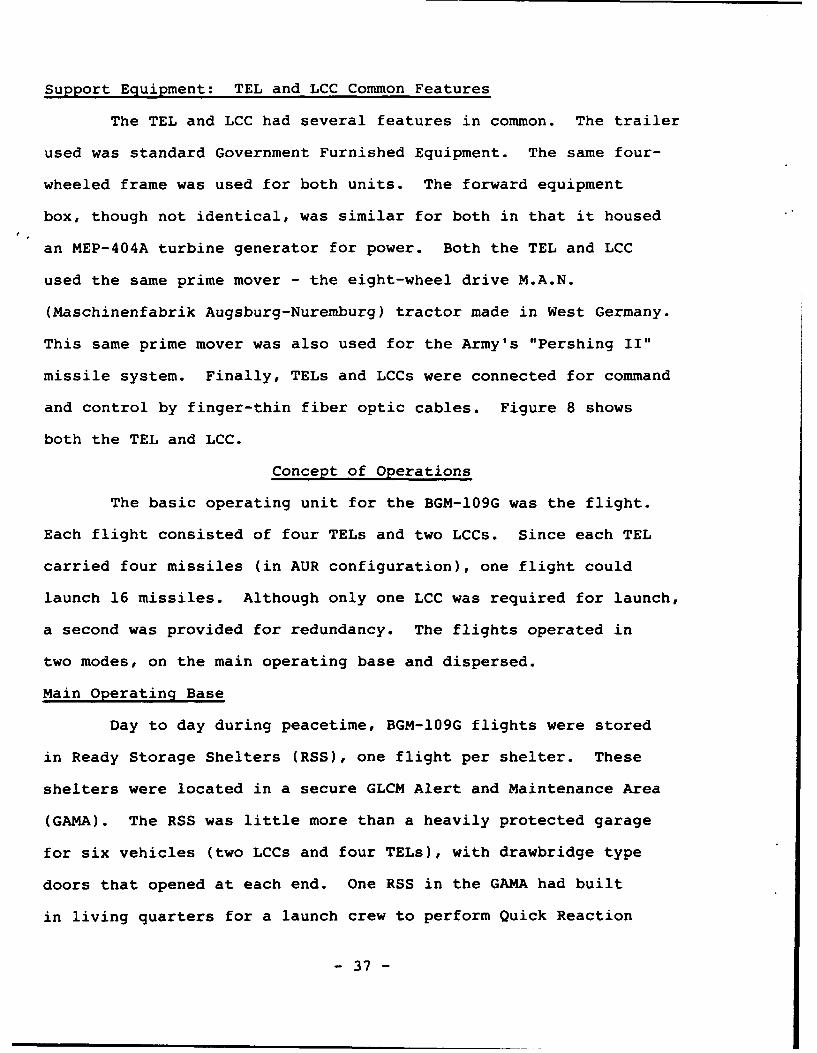
Support Equipment: TEL and LCC Common Features
The TEL and LCC had several features in common. The trailer
used was standard Government Furnished Equipment. The same four-
wheeled frame was used for both units. The forward equipment
box, though not identical, was similar for both in that it housed
an MEP-404A turbine generator for power. Both the TEL and LCC
used the same prime mover - the eight-wheel drive M.A.N.
(Maschinenfabrik Augsburg-Nuremburg) tractor made in West Germany.
This same prime mover was also used for the Army's "Pershing II"
missile system. Finally, TELs and LCCs were connected for command
and control by finger-thin fiber optic cables. Figure 8 shows
both the TEL and LCC.
Concept of Operations
The basic operating unit for the BGM-109G was the flight.
Each flight consisted of four TELs and two LCCs. Since each TEL
carried four missiles (in AUR configuration), one flight could
launch 16 missiles. Although only one LCC was required for launch,
a second was provided for redundancy. The flights operated in
two modes, on the main operating base and dispersed.
Main Operating Base
Day to day during peacetime, BGM-109G flights were stored
in Ready Storage Shelters (RSS), one flight per shelter. These
shelters were located in a secure GLCM Alert and Maintenance Area
(GAMA). The RSS was little more than a heavily protected garage
for six vehicles (two LCCs and four TELs), with drawbridge type
doors that opened at each end. One RSS in the GAMA had built
in living quarters for a launch crew to perform Quick Reaction
- 37 -
Alert (QRA). The wing alternate command post was located adjacent
to the QRA crew area to take advantage of the hardened protection
against conventional attack afforded by this facility. If needed,
the QRA crew had the capability to launch their missiles from
the GAMA by pulling the TELs out of the shelters for execution.
Commercial power was used in lieu of the MEP-404 generators on
the vehicles.
Dispersal
A key attribute of the BGM-109G was its high survivability
through mobility. In advanced states of readiness, during the
transition from peace to war, flights would leave the GAMA, marshal
with their dispersal support vehicles, and depart the main operating
base. The complete dispersal flight composition is found at Appendix
F. Normally, the flight traveled in two cells, with two TELs
and one LCC in each. This gave each cell an independent launch
capability. In the event launch crews in the LCCs received an
emergency action message directing employment of one or more missiles
during this "road march," each cell would proceed to the nearest
preselected enroute launch point, hastily emplace, and execute
launch.
Upon arrival at a preselected and surveyed dispersal site
(that was never used in peacetime), a more orderly defensive position
and emplacement was possible, to include camouflage netting over
the lowered TELs and LCCs. Continual security and alert duty
was performed. Each flight remained dependent on the main operating
base for resupply and other logistical support, but could act
as an independent unit in the event the base was destroyed. The
- 38 -

flight was programmed to relocate to new dispersal sites periodically
until all missiles were expended or directed to return to the
main operating base. Training for this dispersal mission was
the most rigorous and challenging aspect of peacetime operations.
This training was conducted at selected field training ranges
in the host country, which were obtained through bilateral
negotiations.
Operational History
Initial plans for Intermediate Nuclear Forces modernization
called for the deployment of 464 BGM-109Gs (29 flights) and 108
"Pershing IIs." All 108 Army "Pershing IIs" were deployed in
Germany at Neu Ulm and Schwabish Gemund. Five nations agreed
to host the BGM-109G: The United Kingdom, Italy, Germany, Belgium,
and The Netherlands. Although the first unit to reach initial
operational capability was in the UK (501st TMW), Italy was the
first of the five to agree to host cruise missiles. Deployment
was frozen on 9 Dec 87 at 304 missiles (19 flights), when President
Reagan and President Gorbachev concluded the INF Treaty in
Washington. Appendix C shows the individual Air Force units,
their locations, and planned/actual deployments of the BGM-109G.
When GLCM was in development, initial plans were made for
a possible deployment to the Pacific in Korea. Although one advance
planner was assigned to Headquarters, Pacific Air Forces, all
plans of this nature were canceled early in the process.
The 868th Tactical Missile Training Group at Davis-Monthan
AFB AZ served as Tactical Air Command's "schoolhouse" for personnel
assigned to GLCM prior to transfer overseas. Here personnel were
- 39 -
trained in GLCM unique gro- id combat skills prior to reporting
to their operational units in theater.
Phase Out
The INF Treaty was ratified in June, 1988 by the US Senate.
Under the provisions of the treaty, all GLCMs and their launchers
were to be destroyed.within three years (June, 1991), except for
several as static display museum pieces. This has been completed.
Warheads and LCCs were not restricted by the treaty provisions.
In addition, former GLCM bases are subject to inspection for up
to 13 years from the time the INF Treaty entered into force.
All bases remain within this inspection window to this date.
Contributions to Deterrence
The deep commitment of the US and NATO Allies to the GLCM
(and "Pershing II") deployments were instrumental in bringing
the Soviets to the negotiating table. With the INF Treaty, this
class of missiles/nuclear weapons has been eliminated. This treaty
was the first in arms control efforts to have built in verification
and inspection provisions. It also became the framework for even
broader arms control initiatives such as the Strategic Arms
Limitation Treaty (START) and Conventional Forces in Europe (CFE)
Treaty.
While the BGM-109G was deployed, it provided a highly mobile,
and therefore survivable nuclear deterrent capability, attained
through a sound concept of operations. These missiles allowed
theater commanders more flexibility and were able to free up more
dual capable aircraft for conventional missions. While US Air
Force crews manned GLCM LCCs, these (and "Pershing II") missiles
- 40 -
were placed under NATO command and control. It was also an extremely
cost effective deterrent, since the missiles were never fired,
or even "run up" as in the case of the old "Matador." Concurrently,
it capitalized on the significant breakthroughs associated with
modern cruise missile technology. Finally, it sent an extremely
strong and visible political signal to our allies and adversaries
alike. Its deployment in five NATO nations bolstered Alliance
solidarity, despite growing antinuclear movement in the mid and
late 1980s.
- 41 -
POSTSCRIPT
Conclusions
The overview to this work indicated that neither the
TM-61 nor TM-76 weapon systems incorporated the proper technology
and concepts of operation to make them truly effective weapon
systems. Although the BGM-109G incorporated both, it has now
been retired as a result of arms control agreements. This final
section will compare and contrast the key areas. For purposes
of this comparison, the "Matador" and "Mace" (M/M) will be considered
as one.
Technology
- Size: M/M were in the truest sense of the word pilotless
airplanes. Their size was that of a small jet, and their engines
were short life versions of those used in contemporary fighters
and trainers. Nuclear warheads of the period were also bulky.
Although launched from a zero-length launcher, their size tied
with a predictable flight plan threatened post launch survivability.
Technological improvements in the BGM-109G in warhead, engine,
and guidance set size allowed the missile to be built much smaller
and consequently present a greatly reduced radar cross section.
- Components: Partially due to size, "some assembly required"
definitely hindered the M/M concept of operations. Assembly of
major components prior to launch extended launch preparation time
to what would be unacceptable levels today. The components
themselves were relatively fragile, which hindered reliability.
Their size hindered mobility. The BGM-109G was completely self
contained in its All-Up-Round configuration. No component assembly
- 42 -
was required, and even during routine base level maintenance,
the missile would never have to be completely removed from its
canister.
- Guidance: The M/M navigation systems were the single greatest
limitation to success. Though innovative, they were generally
categorized as unreliable, inaccurate, range-limiting, and subject
to jamming. The superb TERCOM system in the BGM-109G eliminated
all these problems.
- Support Equipment: Technology also hindered the effectiveness
of M/M support equipment. The number of support vehicles required
to effect launch ranged from 28 in the TM-61 to only two in the
BGM-109G. Of note, the unique "Teracruzer" prime mover with its
paletized mission cargo was an innovative improvement used in
the TM-76A system.
Concept of Operations
- Unmanned Aspects: As noted earlier in this work, senior Air
Force leaders have been traditionally concerned primarily with
manned aircraft. As an understandable side effect, GLCMs have
historically received only secondary importance. Despite the
many advantages offered by cruise missiles, they drew both manpower
and money away from Air Force "bread and butter" - the manned
aircraft. Consequently the ingrained resistance to these systems
must be frankly realized when studying their role in US Air Force
service.
- Doctrine: The Air Force never developed any consistent GLCM
doctrine. A comparison of V-1, M/M, and BGM-109G operations shows
only the most rudimentary similarity. Technology again was largely
- 43 -
esponsible. There were significant technological "leaps" between
ach system. Serious prelaunch survivability concerns inherent
n the V-1 concept of operations effectively ruled out application
o M/M. Changes and improvements in M/M give the distinct impression
f adaptation and innovation rather than concerted research and
evelopment. While assigned as an operations planner for the
GM-109G, this author knows of no attempt to review M/M concepts
or possible application to "Gryphon."
Mobility: Mobility was not a consideration for the V-1 and
only goal for M/M. Technological limitations gave only a "movable"
apability to these systems, and with it only marginal improvements
n prelaunch survivability. The BGM-109G was the only true mobile
;LCM and its high prelaunch survivability was a key aspect of
.ts deterrent value.
This comparison has shown that GLCM technology and concepts
rere inseparably intertwined and mutually influential towards
:ontributing to nuclear deterrence. It appears we will never
,ee missiles of this type deployed again; they accomplished their
iission. But it is important to record and assess their historical
;ignificance and their roles in US national security. This point
ras unintentionally driven home during research on this work,
rhen the author contacted General Dynamics concerning information
tbout the BGM-109G. The return mail included only a photograph
rith a short note that read in part, "Sorry, but this (the photo)
.s all we have left in our files. I couldn't even locate a
irochure."
- 44 -
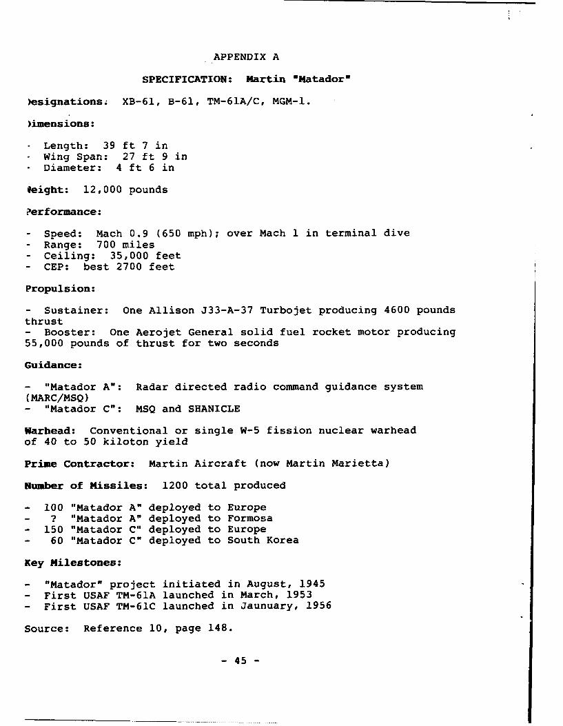
APPENDIX A
SPECIFICATION: Martin "Matador"
)esignationsz XB-61, B-61, TM-61A/C, MGM-l.
)imensions:
Length: 39 ft 7 inWing Span: 27 ft 9 inDiameter: 4 ft 6 in
leight: 12,000 pounds
?erformance:
- Speed: Mach 0.9 (650 mph); over Mach 1 in terminal dive- Range: 700 miles- Ceiling: 35,000 feet- CEP: best 2700 feet
Propulsion:
- Sustainer: One Allison J33-A-37 Turbojet producing 4600 poundsthrust- Booster: One Aerojet General solid fuel rocket motor producing55,000 pounds of thrust for two seconds
Guidance:
- "Matador A": Radar directed radio command guidance system(MARC/MSQ)- "Matador C": MSQ and SHANICLE
Warhead: Conventional or single W-5 fission nuclear warhead
of 40 to 50 kiloton yield
Prime Contractor: Martin Aircraft (now Martin Marietta)
Number of Missiles: 1200 total produced
- 100 "Matador A" deployed to Europe- ? "Matador A" deployed to Formosa- 150 "Matador C" deployed to Europe- 60 "Matador C" deployed to South Korea
Key Milestones:
- "Matador" project initiated in August, 1945- First USAF TM-61A launched in March, 1953- First USAF TM-61C launched in Jaunuary, 1956
Source: Reference 10, page 148.
- 45 -
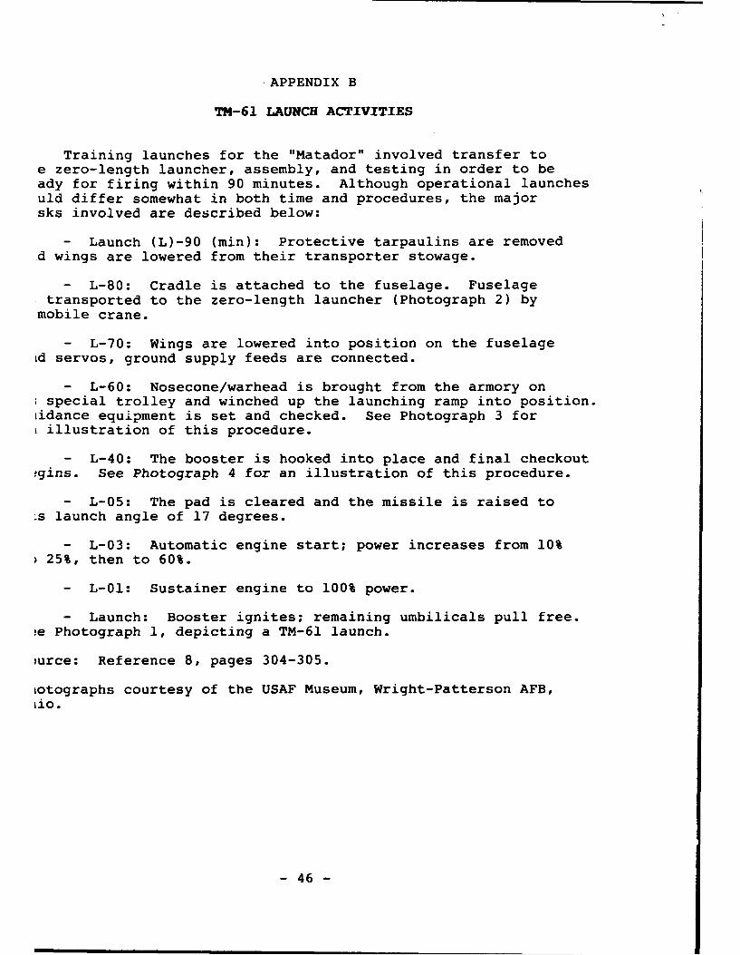
APPENDIX B
TM-61 LAUNCH ACTIVITIES
Training launches for the "Matador" involved transfer toe zero-length launcher, assembly, and testing in order to beady for firing within 90 minutes. Although operational launchesuld differ somewhat in both time and procedures, the majorsks involved are described below:
- Launch (L)-90 (min): Protective tarpaulins are removedd wings are lowered from their transporter stowage.
- L-80: Cradle is attached to the fuselage. Fuselagetransported to the zero-length launcher (Photograph 2) by
mobile crane.
- L-70: Wings are lowered into position on the fuselageid servos, ground supply feeds are connected.
- L-60: Nosecone/warhead is brought from the armory onspecial trolley and winched up the launching ramp into position.
iidance equipment is set and checked. See Photograph 3 fori illustration of this procedure.
- L-40: The booster is hooked into place and final checkout!gins. See Photograph 4 for an illustration of this procedure.
- L-05: The pad is cleared and the missile is raised to-s launch angle of 17 degrees.
- L-03: Automatic engine start; power increases from 10%25%, then to 60%.
- L-01: Sustainer engine to 100% power.
- Launch: Booster ignites; remaining umbilicals pull free.!e Photograph 1, depicting a TM-61 launch.
)urce: Reference 8, pages 304-305.
iotographs courtesy of the USAF Museum, Wright-Patterson AFB,Lio.
- 46 -

.APPENDIX C
ORGANIZATIONAL LINEAGE
Sources: References 10, pages 144-50, and 20, pages 107-109.
MARTIN SSM/B-61/TM-61/MGM-1 -MATADOR-
TESTING
4802nd Guided Missile Squadron formed at Patrick AFB, Floridafor research and development purposes; became the:
6555th Guided Missile Wing (later moved to Cape Canaveral, Floridawith operational testing at Holloman AFB, New Mexico).
- lst Pilotless Bomber Squadron (PBS) (light) formed 1 Oct 51at Patrick AFB.
- 2nd PBS (light) formed 10 Jan 52.
"MATADOR A" EUROPEAN DEPLOYMENT
Headquarters, United States Air Forces, Europe.
Headquarters, 12th Air Force.
-- 36th Tactical Fighter Wing (logistic support andoperational control) beginning 14 Mar 55.
--- lst PBS (TAC) deployed to Bitburg AB GE with 50missiles, arriving 20 Mar 54. This unit was redesignatedthe lst Tactical Missile Squadron (TMS) in Jun 55concurrent with the missile's redesignation as TM-61A.
-- 50th Tactical Fighter Wing (logistic support andoperational control) beginning 14 Mar 55.
--- 2nd PBS (TAC) deployed to Hahn AB GE with 50missiles, arriving I Oct 54. This unit was redesignatedthe 69th TMS in Jun 55 concurrent with the missile'sredesignation as TM-61A.
-- Both squadrons were brought under the 7382 Guided MissileGroup, formed at Hahn AB on 1 Feb 56, for logistic supportand operational control, relieving the 36th and 50th TFWs.
(Note: "Matador A" completely phased out of Europe by May, 1957.)
"MATADOR A" PACIFIC DEPLOYMENT
- The 17th TMS on Taiwan (Formosa) was the first TM-61A missileunit deploy in Asia. Numbers deployed, operating locations,
and operational history for this unit are unknown.
- 47 -
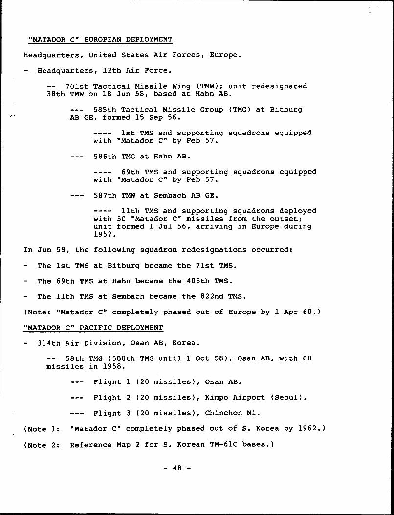
"MATADOR C" EUROPEAN DEPLOYMENT
Headquarters, United States Air Forces, Europe.
- Headquarters, 12th Air Force.
-- 701st Tactical Missile Wing (TMW); unit redesignated38th TMW on 18 Jun 58, based at Hahn AB.
--- 585th Tactical Missile Group (TMG) at BitburgAB GE, formed 15 Sep 56.
ist TMS and supporting squadrons equippedwith "Matador C" by Feb 57.
--- 586th TMG at Hahn AB.
69th TMS and supporting squadrons equippedwith "Matador C" by Feb 57.
--- 587th TMW at Sembach AB GE.
llth TMS and supporting squadrons deployedwith 50 "Matador C" missiles from the outset;unit formed 1 Jul 56, arriving in Europe during1957.
In Jun 58, the following squadron redesignations occurred:
- The 1st TMS at Bitburg became the 71st TMS.
- The 69th TMS at Hahn became the 405th TMS.
- The llth TMS at Sembach became the 822nd TMS.
(Note: "Matador C" completely phased out of Europe by 1 Apr 60.)
"MATADOR C" PACIFIC DEPLOYMENT
- 314th Air Division, Osan AB, Korea.
-- 58th TMG (588th TMG until 1 Oct 58), Osan AB, with 60missiles in 1958.
--- Flight 1 (20 missiles), Osan AB.
--- Flight 2 (20 missiles), Kimpo Airport (Seoul).
--- Flight 3 (20 missiles), Chinchon Ni.
(Note 1: "Matador C" completely phased out of S. Korea by 1962.)
(Note 2: Reference Map 2 for S. Korean TM-61C bases.)
- 48 -

ORGANIZATIONAL LINEAGE (Cont.)
MARTIN TM-61B/TM-76/MGM-13/CGM-13 -MACE-
"MACE A" EUROPEAN DEPLOYMENT
Headquarters, 12th Air Force.
- 38 TMW.
-- 585th TMG.
--- The 71st TMS at Bitburg AB GE would never receive"Mace A." They were ordered to retain the "MatadorC" due to delays in replacing all-weather aircraftcapability with the F-105. This unit would transitiondirectly to "Mace B."
-- 586th TMG.
--- The 405th TMS at Hahn AB GE with 50 missiles.
-- 587 TMG.
--- The 822nd TMS at Sembach AB GE with 50 missiles.
- By September, 1962, three additional 38th TMW squadrons wereadded to the existing force, with 50 missiles each, bringingthe total to 250 "Mace A" missiles.
-- The 89th TMS at Hahn AB GE.
-- The 823rd and 887th TMS' at Sembach AB GE.
(Note: "Mace A" completely phased out of Europe by Sept, 1966.)
"MACE A" PACIFIC DEPLOYMENT - None.
"MACE B" EUROPEAN DEPLOYMENT
Headquarters, 12th Air Force.
- 38th TMW.
-- By September 1965, 50 "Mace B" missiles and their hardenedlaunchers were deployed to the 71 TMS, Bitburg AB GE.
(Note 1: "Mace B" completely phased out of Europe by 1 May,1969.)
(Note 2: Reference Map 1 for German TM-61 and TM-76 bases.)
- 49 -
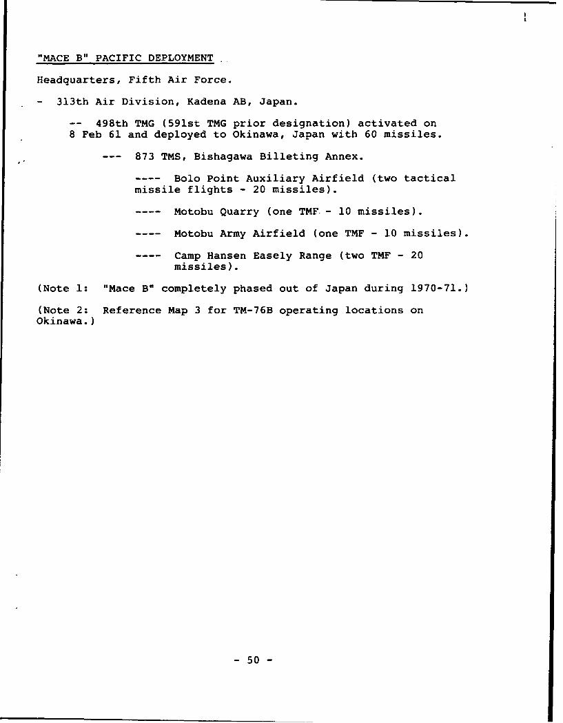
"MACE B" PACIFIC DEPLOYMENT
Headquarters, Fifth Air Force.
- 313th Air Division, Kadena AB, Japan.
-- 498th TMG (591st TMG prior designation) activated on8 Feb 61 and deployed to Okinawa, Japan with 60 missiles.
--- 873 TMS, Bishagawa Billeting Annex.
Bolo Point Auxiliary Airfield (two tacticalmissile flights - 20 missiles).
Motobu Quarry (one TMF. - 10 missiles).
Motobu Army Airfield (one TMF - 10 missiles).
Camp Hansen Easely Range (two TMF - 20missiles).
(Note 1: "Mace B" completely phased out of Japan during 1970-71.)
(Note 2: Reference Map 3 for TM-76B operating locations onOkinawa.)
- 50 -
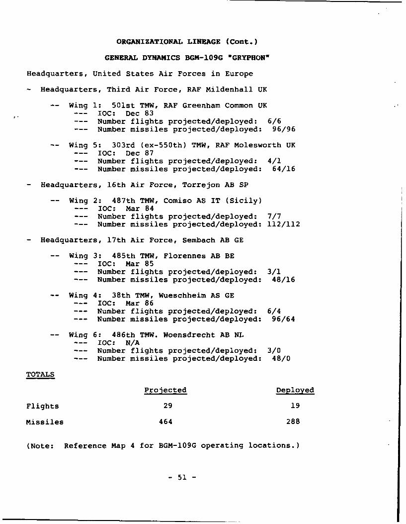
ORGANIZATIONAL LINEAGE (Cont.)
GENERAL DYNAMICS BGM-109G "GRYPHONa
Headquarters, United States Air Forces in Europe
- Headquarters, Third Air Force, RAF Mildenhall UK
Wing 1: 501st TMW, RAF Greenham Common UK--- IOC: Dec 83--- Number flights projected/deployed: 6/6--- Number missiles projected/deployed: 96/96
Wing 5: 303rd (ex-550th) TMW, RAF Molesworth UK--- IOC: Dec 87--- Number flights projected/deployed: 4/1--- Number missiles projected/deployed: 64/16
- Headquarters, 16th Air Force, Torrejon AB SP
-- Wing 2: 487th TMW, Comiso AS IT (Sicily)--- IOC: Mar 84--- Number flights projected/deployed: 7/7--- Number missiles projected/deployed: 112/112
- Headquarters, 17th Air Force, Sembach AB GE
Wing 3: 485th TMW, Florennes AB BE--- IOC: Mar 85--- Number flights projected/deployed: 3/1--- Number missiles projected/deployed: 48/16
Wing 4: 38th TMW, Wueschheim AS GE--- IOC: Mar 86--- Number flights projected/deployed: 6/4--- Number missiles projected/deployed: 96/64
Wing 6: 486th TMW. Woensdrecht AB NL--- IOC: N/A--- Number flights projected/deployed: 3/0--- Number missiles projected/deployed: 48/0
TOTALS
Projected Deployed
Flights 29 19
Missiles 464 288
(Note: Reference Map 4 for BGM-109G operating locations.)
- 51 -
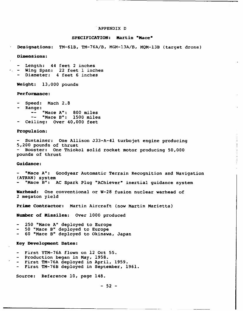
APPENDIX D
SPECIFICATION: Martin "Macew
Designations: TM-61B, TM-76A/B, MGM-13A/B, MQM-13B (target drone)
Dimensions:
- Length: 44 feet 2 inches- Wing Span: 22 feet 1 inches- Diameter: 4 feet 6 inches
Weight: 13,000 pounds
Performance:
- Speed: Mach 2.8- Range:
-- "Mace A": 800 miles-- "Mace B": 1500 miles
- Ceiling: Over 40,000 feet
Propulsion:
- Sustainer: One Allison J33-A-41 turbojet engine producing5,200 pounds of thrust- Booster: One Thiokol solid rocket motor producing 50,000pounds of thrust
Guidance:
- "Mace A": Goodyear Automatic Terrain Recognition and Navigation(ATRAN) system- "Mace B": AC Spark Plug "AChiever" inertial guidance system
Warhead: One conventional or W-28 fusion nuclear warhead of
2 megaton yield
Prime Contractor: Martin Aircraft (now Martin Marietta)
Number of Missiles: Over 1000 produced
- 250 "Mace A" deployed to Europe- 50 "Mace B" deployed to Europe- 60 "Mace B" deployed to Okinawa, Japan
Key Development Dates:
- First YTM-76A flown on 12 Oct 55.- Production began in May, 1958.- First TM-76A deployed in April, 1959.- First TM-76B deployed in September, 1961.
Source: Reference 10, page 148.
- 52 -
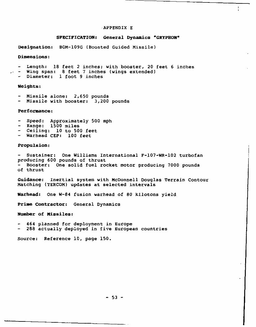
APPENDIX E
SPECIFICATION: General Dynamics *GRYPHON'
Designation: BGM-109G (Boosted Guided Missile)
Dimensions:
- Length: 18 feet 2 inches; with booster, 20 feet 6 inches- Wing span: 8 feet 7 inches (wings extended)- Diameter: 1 foot 9 inches
Weights:
- Missile alone: 2,650 pounds- Missile with booster: 3,200 pounds
Performance:
- Speed: Approximately 500 mph- Range: 1500 miles- Ceiling: 10 to 500 feet- Warhead CEP: 100 feet
Propulsion:
- Sustainer: One Williams International F-107-WR-102 turbofanproducing 600 pounds of thrust- Booster: One solid fuel rocket motor producing 7000 poundsof thrust
Guidance: Inertial system with McDonnell Douglas Terrain Contour
Matching (TERCOM) updates at selected intervals
Warhead: One W-84 fusion warhead of 80 kilotons yield
Prime Contractor: General Dynamics
Number of Missiles:
- 464 planned for deployment in Europe- 288 actually deployed in five European countries
Source: Reference 10, page 150.
- 53 -
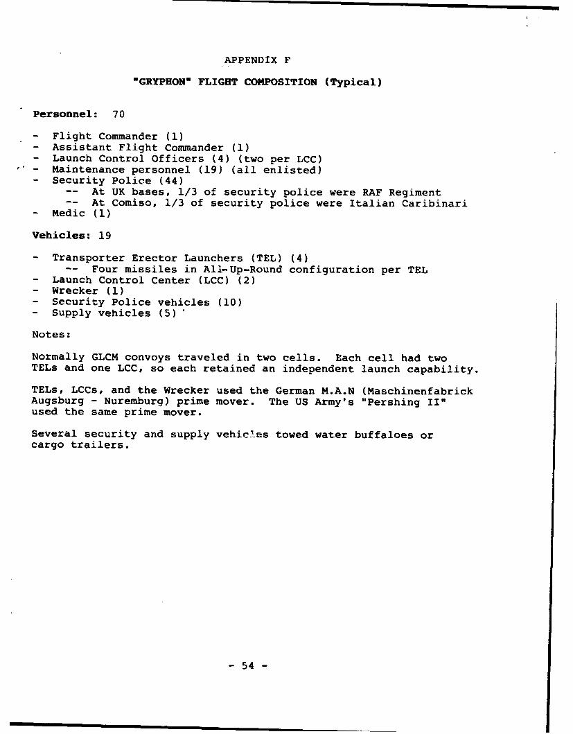
APPENDIX F
"GRYPHON" FLIGHT COMPOSITION (Typical)
Personnel: 70
- Flight Commander (1)- Assistant Flight Commander (1)- Launch Control Officers (4) (two per LCC)- Maintenance personnel (19) (all enlisted)- Security Police (44)
-- At UK bases, 1/3 of security police were RAF Regiment-- At Comiso, 1/3 of security police were Italian Caribinari
- Medic (1)
Vehicles: 19
- Transporter Erector Launchers (TEL) (4)-- Four missiles in All-Up-Round configuration per TEL
- Launch Control Center (LCC) (2)- Wrecker (1)- Security Police vehicles (10)- Supply vehicles (5)'
Notes:
Normally GLCM convoys traveled in two cells. Each cell had twoTELs and one LCC, so each retained an independent launch capability.
TELs, LCCs, and the Wrecker used the German M.A.N (MaschinenfabrickAugsburg - Nuremburg) prime mover. The US Army's "Pershing II"used the same prime mover.
Several security and supply vehicles towed water buffaloes orcargo trailers.
- 54 -
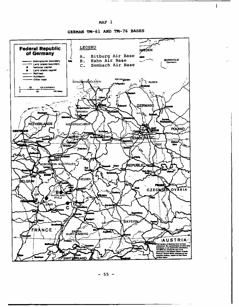
MAP1
GERMAN TM-61 AND TM-76 BASES
14 ...
Federal Republic LEGEND1 ENN
of Gerany ~ A. Bitburg Air Base_
Internationial boundary Eag B. Hahn Air Base BORNIHOLOW
Land (state) boundary ' ' A r B s ~ ,emk
* National capital C. Semblach i Bs* Land (state) capital
R ailroad- Autobahn
- Other road - ~ asr ~ UE
O 50 100 Kilometers
o 50 l;o Mon C
7~ ERMANS N
-N ER D-IESC$
5E
ORD IN-W STFALEN) EPB
GIESE
CZEC OVAKIA
PFALZ
S R -C
WURT MBERG
AS TA I-A-
40,16" no upft. s."W. .w4
-55 -
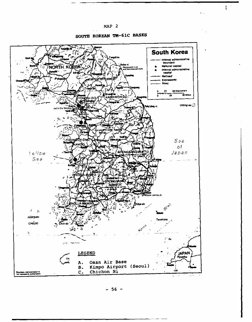
MAP 2
SOUTH KOREAN T14-61C BASES
7.Sut Korea__
- IZ Inera administrativ
im-fUIIboundary
N KNtinlcaiaCHED
Waahm £.Itn~
A. Osan AiraBas
B. Ki5p Airor (Seoul)C. ChiCh;nN
INCH'bN-~ 56A4 -logd
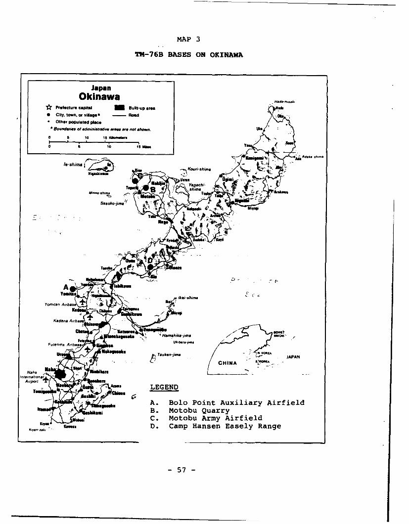
MAP 3
TH-76B BASES ON OKINAWA
JapanOkinawa
Prefecture Capital Built-up ores
* City, town, or villages Road ;b* Other Populated place
Boundaries of adminiatraftwe waree are not shown. like
o 1 0 I sM b
Yoi a I~bs , . I N
0 aen A0 i baa y
Futenma ,,bassUa-.,hjmm
,,a---im Mai E JPA
A.isbas Bo71 n uilayArilB. nMtobs uar
C. Motobu ArmyAirielSD. Camp 4sHiansnEsl ag
-57 -e
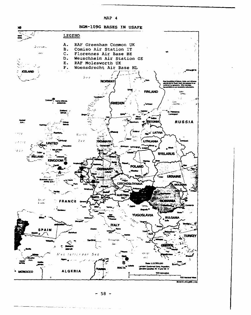
MAP 4
le BGM-109G BASES IN USAFE
-~ -- LEGEND
A. RAF Greenham Common UKB. Comiso Air Station IT MC. Florennes Air Base BED. Weuschheim Air Station GEE. RAF Molesworth UKF. Woensdrecht Air Base NL
NORWAY Ow w 'uw
-FINLAND
SWEDEN*u~w
* SL Pdwsba- .- ' (LUusod)
0100
hfdwkPoTAI RUSSIA
*100
e-eUTUM
As
Jinsyo L(
Heme
uix) -Z
C Pisoma
`7 AUGOSLAVA60170(0166120
MALY
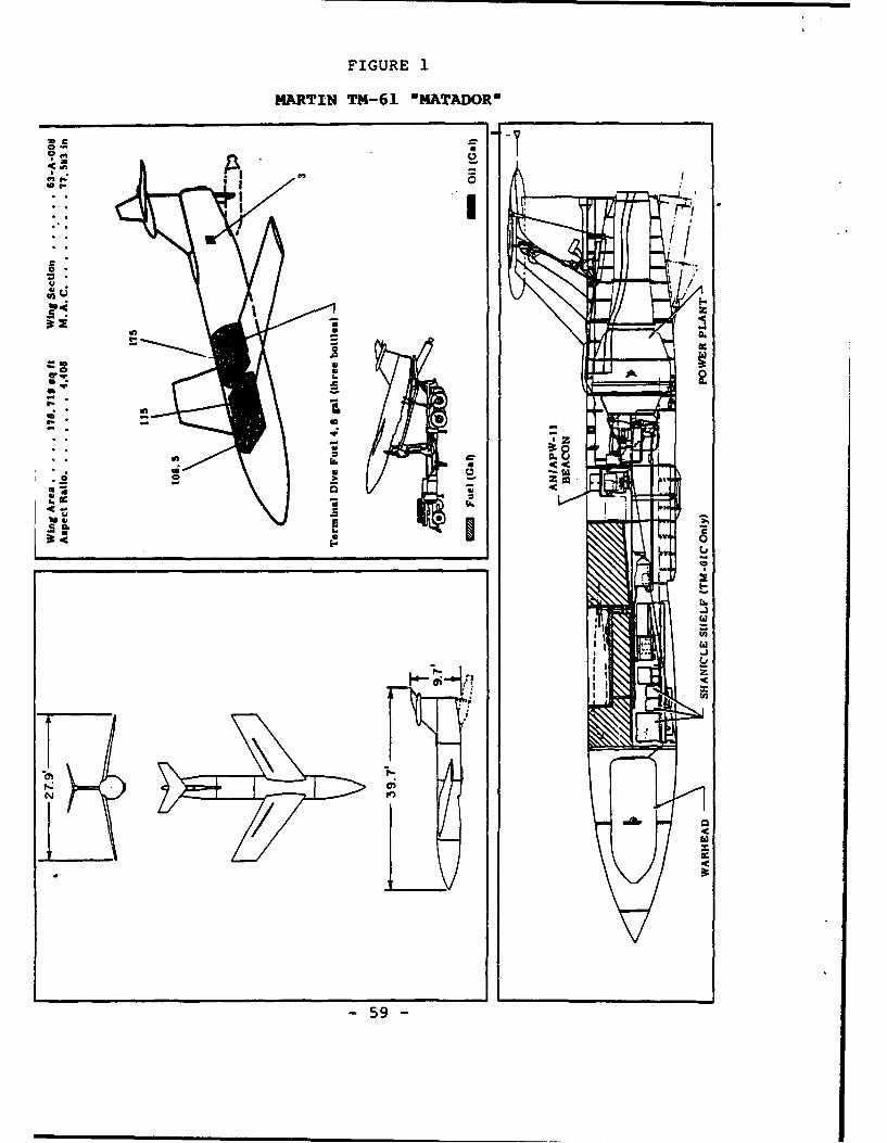
FIGURE 1
MARTIN TM-61 "MATADORN
"" 0
o-mar
- Im
pito-
-59
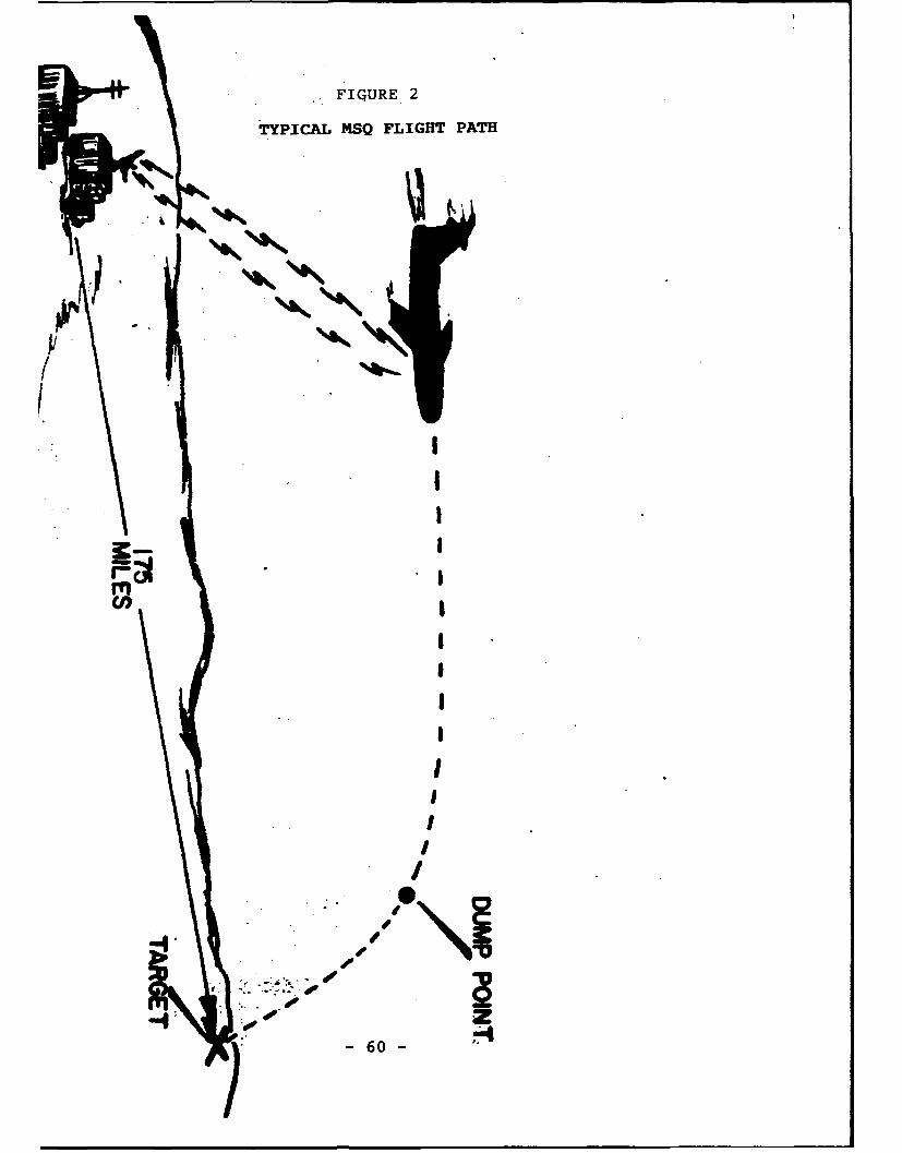
.• .. FIG~URE 2
TYPICAL MSQ FLIGHT PATH
I I!
m!
IIII
1I
•,• " . .I
.-4 ,-js
)• -60 -
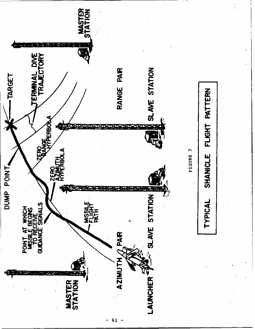
40
0 0.
w W.
0Cl) C
4 I-L
W I-
OW 5 -zz
CL ii
CL z
a-
4 .4QOON a
zcnI- n
61-
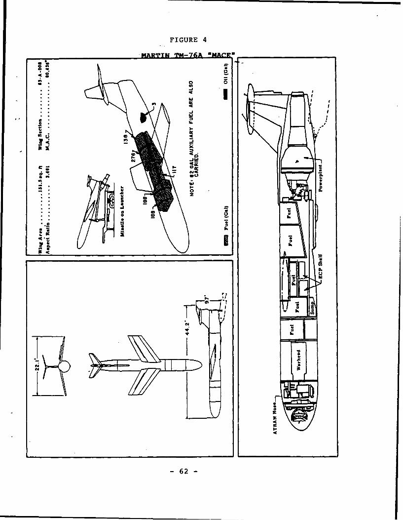
FIGURE 4
MARTIN TM-76A nAR __________
o on
404
ai
WOC
*.2
* a6
bi -
TTV
620
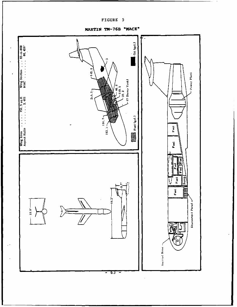
FIGURE 5
MARTIN TM-76B "MACE"
CZ,
~I!
CC
C--1
b.3
C. N
U,1
, C,CU~ cZ
---
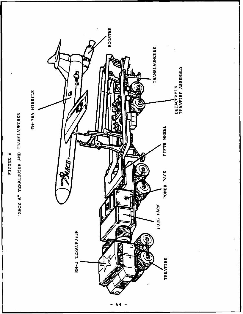
1E-4
'00
'00
~uI-I z
UD
E- E4n
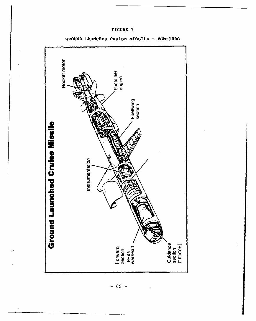
FIGURE 7
GROUND LAUNCHED CRUISE MISSILE - BGM-109G
--0
E
0oo4
mi
00
16
77
nLt c0I65
• tS 2
'U°,a,
0 /
0
I•-~
- 65 -
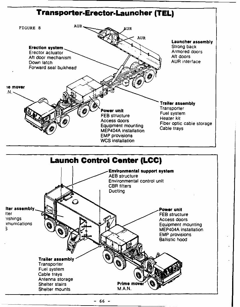
Transporter.Erector.Launcher (TEL)
FIGURE 8 AUR UR
AURLauncher assembly
Erection system Strong backErector actuator Armored doorsAft door mechanism / Aft doorsDown latch AUR interfaceForward seal bulkhead
.N.
"Trailer assemblyw Transporter
-Power unit Fuel systemFEB structure Heater kitAccess doors Fiber optic cable storageEquipment mounting Cable traysMEP404A installationEMP provisionsWCS installation
Launch Control Center (LCC)Environmental support systemAEB structure
Environmental control unit~CBR filtersDucting
Iter assemblyPower unitIter . FEB structureiishings Access doorsimunications Equipment mounting
* MEP404A installationEMP provisionsBallistic hood
Trailer assemblyTransporterFuel systemCable traysAntenna storageShelter stairs Prime moveIr
Shelter mounts MAN.
- 66 -

-L9-
HONOV¶I HqISSIN T9-W~l
T HdV'dDOJ.OHd
:41
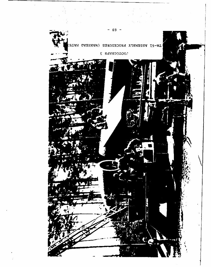
-69-
Q~W~VM)sa'ancaDou1a XrSwassv T9-WiL
- - HdVHDOIOHC'

- 99
Ua~HONflVrI HDLN2arI-OHIZ T9-W.L
z H4dvuDOmloHd

-OL-
V~ HdVUDOJOHd
Jl
X713MV7SMV1 NO GalMfOW V9L-WI
s: Hduo'l
9%Az
~~r4
V9L-WL 3111 90a I12AOW 3WI~d T-WW
9 HdVHDEOJ.O11d
dI.
rA

XLI1IIDVd HDNnV'1 RqdIlqnfW Iala QIdVHd
L HdVHDOIOHd
4L
74 -
LIST OF REFERENCES
1. MSgt Gary R. Akin, "Evolution and Development of CruiseMissiles," Air Power History, Vol. 38, No. 2, Summer,1991, pp. 43:48, Air Force Historical Foundation:1991.
2. Dr. David Baker, PhD., The Rocket, The History and Developmentof Rocket and Missile Technology, London: New CavendishBooks, 1978.
3. Dr. James A. Bell, PhD., "The Mighty Mace," The Airman, August,1961, pp. 18-19.
4. Robert Berman and Bill Gunston, Rockets and Missiles ofWorld War III, London, New York, Sydney, and Toronto:Hamlyn (Bison Books Corp.), 1983.
5. Ronald Farquhar, "Matadors in Germany," Royal Air Force FlyingReview, August, 1954, pp. 20-21.
6. Fifth Air Force History, 1 Jan through 30 Jun 58, DocumentNo. 5FCAGI2070.
7. Bernard Fitzsimons, Editor, Weapons and Warfare, TheIllustrated Encyclopedia of 20th Century, Vol. 17,New York: Columbia House, 1969.
8. John Fricker, "The U.S.A.F.'s Operational Guided-missile,"The Aeroplane, August 26, 1955, pp. 300-306.
9. Kennth Gatland, "Martin Mace - Missile with the KnockoutPunch," Royal Air Force Flying Review, Vol XIV, No.1, October, 1958, pp. 43-45.
10. James Norris Gibson, The History of the US Nuclear Arsenal,Greenwich CT: Brompton Books, 1989.
11. Bill Gunston, Rockets and Missiles, London: SalamanderBooks, 1979.
12. History of USAFE, 1 Jan through 30 Jun 1957, Vol I, Narrative,15 Nov 57.
13. Oliver, L. Hobson, Historical Division, Office of InformationServices, History of the Pacific Air Forces, 1 Jul58 - 31 Dec 58.
14. Fred Horky and Dr. Griffin T. Murphy, "Mace/Teracruzer,Part 1," International Plastic Modelers Society Quarterly,Vol. 21, No. 3, Spring, 1986, pp. 5-17, IPMS/USA: 1986.
- 75 -
LIST OF REFERENCES(Continued)
15. HQ TAC/TOOT-TL, TM-61C Operations Summary, 10 Oct 60.
16. Daniel W. Jenkins, Maj Gen, USAF, "The Mace Missile," Ordnance,November-December, 1959. pp. 414-415.
17. Lloyd S. Jones, U.S. Bombers: 1928 to 1980s, Fourth Edition,Fallbrook, CA: Aero Publishers, 1984.
18. Frank G. McGuire, "Mace B Bases Readied on Okinawa," Rocketsand Missiles, March 13, 1961, p. 18.
19. Missilier, the 701st TMW's Magazine, Vol I, No. 2, March,1958.
20. Dr. Walter S. Moody, PhD, Historian, HQUSAFE Office of History,"Air Force Posture in NATO's Central Region, 1947-1976,"USAF Historical Monograph, 17 May 78.
21. Stan Morse, Managing Editor, War Machine, Vol. 1, Issue2, "Surface to Surface Missiles," London: OrbisPublications, 1983.
22. Stan Morse, Managing Editor, War Machine, Vol. 8, Issue85, "Early Strategic Missiles," London: OrbisPublications, 1985.
23. Wayne G. Peterson, Command Historian, The Mace - MatadorGuided Missile Program in the 313 AD, 26 May 59.
24. Carroll S. Shershun, Capt, USAF, "Who Needs Glamour?," TheAirman, August, 1963, pp. 20-23.
25. L.W. Schopp and C.E. Fordham, Goodyear Aircraft Corp., Akron,Ohio, "GSE Design Criteria," Astronautics, December,1958, pp. 34-35, 78.
26. TAWC Information Office, Eglin AFB, FL, and Robert P. Everett,
Capt, USAF, "Old Maces Die Hard," and "Old MissileOn the Firing Line," (respectively) The Airman, March,1969, pp. 18-23.
27. Michael J. H. Taylor, Missiles, Warbirds Illustrated No.12, London, Melbourne, and Harrisburg PA: Arms andArmor Press, 1983.
28. Bernard J. Termena M.A., Historian, Air Materiel Command,History of the Mace and Matador Guided Missiles,1951 - 1957, Historical Study No. 317, Vol I.
- 76 -
LIST OF REFERENCES(Continued)
29. Jack L. Thatcher, 2nd Lt, USAF, Historical Officer, "Historyof the 701st TMW, 1 Jan 58 - 15 Jun 58."
30. TM-61C Missile Operations Handbook, undated, published bythe 701st TMW.
31. TM-76A Training Plan, Document No. TODO-30021, 9 Mar 61.
32. Stanley Ulanoff, The Illustrated Guide to US Missiles andRockets, Garden City, NY: Doubleday and Co., 1959.
33. Kenneth P. Werrell, The Evolution of the Cruise Missile,Maxwell AFB AL: Air University Press, 1985.
34. "Zero Length Launcher," Ordnance, January - February 1955,p. 15.
- 77 -
GLOSSARY
AB Air Base
ALCM Air Launched Cruise Missile
ATRAN Automatic Terrain Recognition & Navigation
AUR All-Up-Round (BGM-109G)
BGM Boosted Guided Missile (as in BGM-109G)
CEP Circular Error Probable (warhead accuracy)
CFE Conventional Forces in Europe (Treaty)
GAMA GLCM Alert & Maintenance Area (BGM-109G)
GLCM Ground Launched Cruise Missile
INF Intermediate Range Nuclear Forces (Treaty)
IOC Initial Operational Capability
ITCP Initial Timing Control Point (BGM-109G)
LBS Abbreviation for Pounds
LCC Launch Control Center (BGM-109G)
MARC/MSQ Manual Airborne Radio Control (TM-61A)
MM-1 Military Model One ("Mace" Teracruzer)
MPH Miles Per Hour
PBS Pilotless Bomber Squadron
QRA Quick Reaction Alert
RATO Rocket Assisted Take Off (booster)
RFML Rapid Fire Multiple Launch (TM-76A)
RSS Ready Storage Structure (BGM-109G)
SHANICLE Short Range Navigation Vehicle (TM-61C)
SSM Surface-to-Surface Missile
START Strategic Arms Reduction Talks
- 78-
GLOSSARY
(Cont.)
TAC Tactical Air Command
TAWC Tactical Air Warfare Center (Eglin AFB)
TEL Transporter-Erector-Launcher (BGM-109G)
TERCOM Terrain Contour Matching (BGM-109G)
TM Tactical Missile (as in TM-61 & TM-76)
TMG Tactical Missile Group
TMS Tactical Missile Squadron
TMW Tactical Missile Wing
USAF United States Air Force
USAFE United States Air Forces in Europe
Vergeltungswaffe German for "Vengeance Weapon" (V-l)
ZEL Zero Length Launcher (TM-61)
- 79 -