Research Report 628 Standardisation of laboratory ... · representative of those found in the...
39
Standardisation of laboratory compaction energies October 2017 R McLachlan and SA Bagshaw Opus Research Opus International Consultants NZ Transport Agency research report 628 Contracted research organisation – Opus Research
Transcript of Research Report 628 Standardisation of laboratory ... · representative of those found in the...

Standardisation of laboratory compaction energies October 2017
R McLachlan and SA Bagshaw Opus Research Opus International Consultants
NZ Transport Agency research report 628 Contracted research organisation – Opus Research

ISBN 978-1-98-851263 (electronic) ISSN 1173-3764 (electronic)
NZ Transport Agency Private Bag 6995, Wellington 6141, New Zealand Telephone 64 4 894 5400; facsimile 64 4 894 6100 [email protected] www.nzta.govt.nz
McLachlan, R and SA Bagshaw (2017) Standardisation of laboratory compaction energies. NZ Transport
Agency research report 628. 39pp.
Opus Research was contracted by the NZ Transport Agency in 2016 to carry out this research.
This publication is copyright © NZ Transport Agency. This copyright work is licensed under the Creative Commons Attribution 4.0 International licence. You are free to copy, distribute
and adapt this work, as long as you attribute the work to the NZ Transport Agency and abide by the other licence terms. To view a copy of this licence, visit http://creativecommons.org/licenses/by/4.0/. While you are free to copy, distribute and adapt this work, we would appreciate you notifying us that you have done so. Notifications and enquiries about this work should be made to the Manager National Programmes, Investment Team, NZ Transport Agency, at [email protected].
Keywords: compaction, compaction effort, compaction energy, granular materials, laboratory compaction, maximum dry density (MDD), optimal moisture content, vibrating hammer, vibrating table.

An important note for the reader
The NZ Transport Agency is a Crown entity established under the Land Transport Management Act 2003. The objective of the Agency is to undertake its functions in a way that contributes to an efficient, effective and safe land transport system in the public interest. Each year, the NZ Transport Agency funds innovative and relevant research that contributes to this objective.
The views expressed in research reports are the outcomes of the independent research, and should not be regarded as being the opinion or responsibility of the NZ Transport Agency. The material contained in the reports should not be construed in any way as policy adopted by the NZ Transport Agency or indeed any agency of the NZ Government. The reports may, however, be used by NZ Government agencies as a reference in the development of policy.
While research reports are believed to be correct at the time of their preparation, the NZ Transport Agency and agents involved in their preparation and publication do not accept any liability for use of the research. People using the research, whether directly or indirectly, should apply and rely on their own skill and judgement. They should not rely on the contents of the research reports in isolation from other sources of advice and information. If necessary, they should seek appropriate legal or other expert advice.

Acknowledgements
The authors acknowledge the time and expertise of the Steering Group: Jayden Ellis and Martin Gribble; and the Peer Reviewers: John Patrick and Allen Browne; for their assistance in developing, discussing and reviewing this work, and for providing valuable insights into the problem.
Abbreviations and acronyms
AC asphalt concrete
ASTM American Society for Testing and Materials
BS/BSI British standards/British Standards Institution
CAPTIF Canterbury Accelerated Pavement Testing Facility
CBR California bearing ratio
ITS indirect tensile strength
MDD maximum dry density
MH Marshall hammer (compaction test)
NZS New Zealand Standard
NDM nuclear density meter
OMC optimal moisture content
RLT repeated load tri-axial test
SGC Superpave gyratory compactor
TRRL Transport and Road Research Laboratory (US)
UCS unconfined compressive strength
UGA unbound granular aggregate
UGP unbound granular pavement

5
Contents
Executive summary ................................................................................................................................................ 6 Abstract ...................................................................................................................................................................... 6 1 Introduction .................................................................................................................................................. 7
1.1 Introduction ........................................................................................................... 7 2 Literature review ........................................................................................................................................ 9
2.1 Cohesion-less material ........................................................................................ 10 2.2 Compaction suitability ......................................................................................... 11 2.3 Repeatability and reproducibility .......................................................................... 11
3 Laboratory compaction methods ...................................................................................................... 13 3.1 Impact compaction .............................................................................................. 13 3.2 Static compaction ................................................................................................ 14 3.3 Kneading compaction .......................................................................................... 15 3.4 Vibratory compaction ........................................................................................... 15
3.4.1 Vibrating hammer.................................................................................... 15 3.4.2 Vibrating table......................................................................................... 18
3.5 Gyratory compaction ............................................................................................ 19 3.6 Particle orientation ............................................................................................... 19
4 Variability of the laboratory vibrating hammer test ................................................................. 21 4.1 General sources of variability in laboratory-based tests ........................................ 21
4.1.1 Operator/technician ................................................................................ 21 4.1.2 Calibration of apparatus .......................................................................... 22 4.1.3 Environment ............................................................................................ 22 4.1.4 Test sample ............................................................................................. 22 4.1.5 Time ....................................................................................................... 23 4.1.6 Measurement of density – laboratory to field ............................................ 23
4.2 Sources of variability specific to vibrating hammer test ......................................... 23 4.2.1 Hammer .................................................................................................. 24 4.2.2 Power ...................................................................................................... 24 4.2.3 Compaction energy/hammer energy ........................................................ 24 4.2.4 Frequency and amplitude......................................................................... 25 4.2.5 Frame ...................................................................................................... 25
4.3 Mould shape and size .......................................................................................... 26 4.3.1 Degradation ............................................................................................ 27 4.3.2 Segregation ............................................................................................. 27 4.3.3 Oversized particles .................................................................................. 28
5 Equipment instrumentation to measure compaction energy ................................................ 29 5.1 Proposed procedure for instrumenting the vibrating hammer equipment .............. 29
6 Summary ..................................................................................................................................................... 31 7 Recommendations for establishing standardised compaction energy ............................. 34 8 References .................................................................................................................................................. 36
8.1 Standards referenced ........................................................................................... 38

6
Executive summary
This research project reviewed the current state of New Zealand laboratory compaction tests and the literature from around the field, with a view to understanding how to standardise the energy of the compaction test methods. Significant work has been undertaken in New Zealand in the area of laboratory aggregate compaction to describe the small number of different test methods that are available, along with the New Zealand vibrating hammer test. All authors have found problems with variability of results from laboratory test methods that affect their correlations with field compaction results.
This review identified a number of components of the New Zealand vibrating hammer test as it is actually performed in laboratories throughout New Zealand, which may contribute to variability. Each of the components may introduce a larger or smaller variability and therefore may or may not need to be addressed. The purpose of this review was to identify those components that may be rectified, within some degree of ranking, to provide for standardisation of compaction energy in the laboratory test method. Correlations with field compaction results will be addressed at a later date.
A number of recommendations have been made into how a standardised test method might be developed, tested and compared with the existing method. A proposal to assess the existing vibratory compaction method is also presented.
Abstract
This research reviewed the New Zealand vibrating hammer laboratory compaction test and energy standardisation thereof. The area of laboratory aggregate compaction was found to have significant problems with variability of results and reduced correlations with field compaction results, which suggests there are problems with standardisation of the compaction energies used.
A list of components of the New Zealand vibrating hammer test as it is actually performed in laboratories throughout New Zealand is provided, with each component introducing a larger or smaller amount of variability into the results. Methods of rectifying each component are identified to improve the standardisation of compaction energy and recommendations are made into how an alternative test method might be developed, tested and compared to the existing methods.

1 Introduction
7
1 Introduction
1.1 Introduction Throughout New Zealand, in the United States and in the United Kingdom, the use of the vibrating hammer compaction test method is widespread for laboratory compaction of aggregates to determine maximum dry density (MDD) and optimum moisture content (OMC). The laboratory values obtained for a given aggregate or aggregate mixture are provided to pavement construction engineers for guidance when constructing unbound granular pavements (UGP) from that aggregate mixture. Furthermore, the same vibrating hammer compaction technique is also used to produce samples for several other pavement and geotechnical-related test methods including: California bearing ratio (CBR), indirect tensile strength (ITS), unconfined compressive strength (UCS) and repeated load tri-axial test (RLT).
However, evidence has been produced which indicates problems throughout New Zealand with the consistency of results from the vibrating hammer test method for laboratory compaction of granular pavement aggregate samples (NZS 4402:1986: Test 4.1.3; Ball 2008; Ellis 2009). In 2008, a working group established that anecdotal evidence of inconsistencies between laboratories and between samples was sufficient to warrant a more in-depth investigation. That investigation, along with subsequent work, described the issues (Ball 2008). A summary of that work then attempted to unpick the issues and describe a series of protocols that might be put in place to rectify apparent inconsistencies in the results (Ellis 2009). At present, the level of compaction of granular materials in the laboratory is believed to be determined by the duration of the compactive effort, or the total amount of compaction energy imparted into the sample. While there are possibly fundamental issues with that understanding, the implication from the Ball 2008 study was that the total energy imparted into the sample can vary between laboratories and between samples due to a range of circumstances, and that will affect the final result in a given UGP.
Patrick and Alabaster (1998) used the Canterbury Accelerated Pavement Testing Facility (CAPTIF) to relate laboratory MDD test values to those developed in CAPTIF, with the view that the CAPTIF samples were representative of those found in the field. This work showed it is possible for laboratory-derived values to match or represent those found in the CAPTIF samples when compacted to NZTA B/2 specification (Transit NZ 2005). Furthermore, investigations via RLT and other methods have been used to make decisions around the M/4 specification 2006). This work also shows it may be possible to better correlate the laboratory vibrating hammer compaction results with those developed by CAPTIF and, par infra, with those values developed in the field (Patrick and Alabaster 1998).
However, the issue being tackled in this review is that of the significant variability and thus inaccuracy across laboratories with the vibrating hammer test, and how that variability might be improved by standardisation of the test method. Improved accuracy and consistency of sample compaction is very important from a quality control perspective in terms of pavement testing, construction and performance. Hence, the current report seeks to understand the protocols that currently exist within the New Zealand compaction testing sector and to investigate concepts that will ensure more accurate compaction testing and standardisation of the energy of compaction of those granular aggregate materials. The question of compaction energies, in regard to testing outcomes, is examined in terms of producing or providing standardised test equipment and methodologies that will deliver the accuracy and consistency that is sought for the laboratory compaction testing. There will be the same issues with the CBR, UCS, RLT etc test samples as there are with the MDD/OMC samples. Therefore this also needs consideration should any changes to existing methods be considered.

Standardisation of laboratory compaction energies
8
It appears that even though there is a New Zealand standard for this test (NZS 4402:1986), the standard is not as rigorous as might be needed and also that laboratories are often not following the standard accurately.

2 Literature review
9
2 Literature review
The literature, and the apparent state of the art, regarding laboratory aggregate compaction in the New Zealand context, has been quite rigorously studied over the past 10 years (Ball 2008; Ellis 2009; Shahin 2010; Karan et al 2014; Karan et al 2017). These investigations have all, without exception, identified that there are issues not only with regard to the consistency and accuracy of laboratory compaction results but also with the actual methods used. Reviews of the subject area from other parts of the world have also attempted to describe laboratory aggregate compaction (Chilukwa 2013; Kelfkens 2008). Those reports have, however, stopped short of developing new solutions to the problems. The majority of the work reviewed herein is based on these reports and the literature reviewed therein.
Compaction of aggregate layers is required during pavement construction to ensure appropriate load support performance by the pavement (Christopher et al 2006). Indeed, compaction is the most popular technique for the general improvement of the properties of an aggregate assembly. Noting that compaction does not change the inherent chemical or mineral properties of the aggregate itself, but rather improves the properties that an assembly of that aggregate will exhibit. Compaction can, however, induce particle breakdown and changes to the particle size distribution. Improvements to the properties of the aggregate assembly created by compaction include (Budhu 2006):
• an increase in shear strength of the aggregate assembly
• a decrease in compressibility, reducing the potential of excessive long-term settlement of fills and soils
• a reduction in permeability, restraining flow of water through the compacted basecourse layer
• a general decrease in void ratio, preventing water from being held within the basecourse layer, maintaining strength and stiffness properties
• achieving a state of increased unit weight.
New Zealand pavements in particular are constructed from unbound granular aggregates (UGA) to prepare the so-called flexible, or UGPs. These types of pavements rely heavily upon reaching specific compaction levels to be able to achieve adequate densities and moduli that lead to adequate design lives (fatigue resistance), under repeated traffic loads. Achieving the desired level of compaction is therefore immensely important (Black 2009). These unbound aggregate structures are in general cohesion-less, therefore a significant degree of particle confinement must occur in order to achieve appropriate stiffness of the UGA matrix. Confinement of the aggregate particles arises due to the internal stresses that develop during construction and post-construction compaction (New Zealand Institute of Highway Technology 2000).
The mechanical behaviour of unbound granular materials is complex. A granular layer is a particulate, not a continuous medium. The response of an element of granular material in a pavement depends on its stress history and the current stress state, in addition to the degree of saturation and density (Araya 2011). Therefore, in order to achieve an optimum degree of compaction, a value for the MDD must be derived. The MDD largely depends on the water content of the aggregate. Therefore, in order to understand what those values should be, preliminary laboratory compaction tests are conducted on the sample to obtain the MDD and corresponding OMC values. Subsequent to obtaining these values from laboratory testing, optimum field compaction can then be targeted according to these values. Contractors are currently required to determine the laboratory MDD and OMC by using the vibrating hammer compaction method specified in NZS 4402: Test 4.1.3. This test will set the target dry density that the contractor must achieve when compaction occurs on the field (Frobel and Moulding 2006; TNZ B/02:

Standardisation of laboratory compaction energies
10
2005). It is generally recognised that either MDD or percent compaction is a good indicator of the state of ‘compactness’ of a given aggregate mass. However, the engineering properties of a given aggregate can vary considerably, therefore, considerable engineering judgement must be used in relating the properties of the aggregate to the state of compaction. This judgement issue means that even if the method were standardised, variability between results will be inevitable. It also means absolute values for MDD are not necessarily obtained by these test methods. Furthermore, the relationship between the peak density and the optimum amplitude of vibration can vary with various soil types and gradations, meaning that different materials may respond differently to even standard tests.
Review of the literature appears to suggest that ‘impact-type’ compaction tests as described below, in general appear to be inadequate for compaction quality control of granular aggregate assemblies. This appears also to have been identified in the New Zealand context where the vibrating hammer test has been adopted over more traditional impact tests. However, as will be discussed below, variation between laboratories and between samples for vibrating hammer testing has been identified (Ball 2008). The MDD value determined by the laboratory compaction testing is used for control of compaction in new road and pavement construction, therefore the laboratory values are very important. The variability that has been identified in the laboratory testing therefore constitutes a high level of risk for contractors and asset owners alike.
Yaghoubi at al (2017) have analysed the nature of field compaction and compared that with laboratory compaction using similar types of methods. Their contention was that field compaction occurs via either kneading (more likely for sub-grade and sub-base) or static-vibratory (eg basecourse) mechanisms. For the latter, effectively, a roller passes over a given point on the pavement for a given time period, and applies a static force that possesses multiple vectors due to the addition of vibration, induced by the rotating/reciprocating masses inside the roller. An implication is that field roller compaction is indeed vibratory, not an impact method like the so-called vibrating hammer method. A further implication is that the two compaction contexts, laboratory and field, are therefore not directly comparable. This may cause downstream issues when results from the two different process are compared and applied (Yaghoubi et al 2017). This view that vibrating rollers do not have an impact on the surface appears not to be universally held, with some operators anecdotally reporting that vibrating rollers do indeed leave the surface of the pavement, thereby creating an impact compaction environment and therefore better correlation with the laboratory method.
Industry information from suppliers such as Dynapac describes the advances being made to compaction equipment, specifically rollers. Advances include different methods and directions of oscillation for the vibration, accelerometers for detecting density changes and a global positioning system (GPS) for ensuring accuracy of location (www.dynapac.com/products/compaction). It very much appears that laboratory testing technologies have lagged behind these developments and in the medium to long term similar types of developments for laboratory testing may be necessary.
2.1 Cohesion-less material Review suggests that most compaction test methods applied in the pavements area were originally developed for use with cohesive soils. However, pavements are generally constructed with cohesion-less granular materials and it is understood these behave differently from cohesive soils (Shahin 2010).

2 Literature review
11
Figure 2.1 Examples of compaction curves for cohesion- less granular material using different compaction
methods (Ramadan 2012)
Forssblad (1981) explained that compaction under oven-dry conditions (0% moisture content) is effective for graded materials with as much as 30% fines. In contrast, Brandl (2001) reported that even though MDD may occur at oven-dry conditions, the MDD value should nevertheless be chosen at its other peak where the OMC lies near saturation. That argument was supported by explaining that if the material was to be compacted at oven-dry conditions it would favour long-term grain rearrangement and hence differential deformation. In general terms, it is understood that the MDD will occur at the OMC. These values may well be different for different types of compaction, as described in figure 2.1. This makes it clear that consistent choice and operation of a compaction method is vital for consistency of results. It also makes it clear that the laboratory result for a given material, may as a consequence of the different types of compaction, have no relationship with the field result.
2.2 Compaction suitability Due to the wide range of aggregate types that are used in UGPs and their behaviours with regard to compaction, a number of different laboratory compaction tests have been developed to suit these different aggregate types. The different portions of the pavement structure are constructed from both potentially cohesive (sub-grade and modified sub-base) and cohesion-less (sub-base, basecourse) granular graded aggregates. It would therefore appear logical to deduce that these different layers may in fact require different compaction methods. It is also likely to be important to analyse the different methods of compaction and determine which may be most appropriate when compacting the different pavement materials.
2.3 Repeatability and reproducibility In development of the British Standard, a 12-laboratory study from 1988 was analysed where repeatability (r) of 0.033 t/m and reproducibility (R) of 0.054 t/m for a gravel sub-base material were found. For a carboniferous limestone sub-base material the repeatability was smaller (r = 0.023 t/m) while the reproducibility was larger (R = 0.122 t/m), (BS EN 13286-4 2003 part 4). The ASTM method states repeatability to be r = 0.05 t/m. At the time, however, reproducibility testing had not been completed. In the New Zealand context, the ‘r’ and ‘R’ values need to be higher to justify a full rework or replacement of the test standard.

Standardisation of laboratory compaction energies
12
The work of Ball (2008) established there is a problem with reproducibility of the vibrating hammer compaction test throughout New Zealand. It was recommended that an ASTM type statistical approach, such as ASTM E 691-95, be applied to analyse the New Zealand test method and standard. Ball used this approach to study the data obtained, but it would appear from the current analysis, that the method might need to be applied to understand the variability in all aspects of the test method and standard.
Table 2.1 Dry density measurement variability, 28 laboratories (Ball 2008)
From Ball (2008), analysis of round robin testing in 28 New Zealand laboratories produced r, and R values for the dry density measurements, given in table 2.1. These analyses showed the New Zealand repeatability results are of the order of the ASTM data, but the reproducibilities are significantly greater than the BS value. The New Zealand values represent upper limits of r and R, because the values of water content varied considerably (Ball 2008).
However, the deep analysis performed by Ball revealed that the r and R values for other measures, such as bulk density, dry density with hammer power and other variables, varied in different ways. Therefore, analysis of the method as it currently stands and modification for control of r and R will not be straightforward.

3 Laboratory compaction methods
13
3 Laboratory compaction methods
The merits of five different laboratory compaction techniques relative to the compaction of granular soils can be analysed. The methods are:
• impact compaction
• static compaction
• kneading compaction
• vibratory compaction
• gyratory compaction.
3.1 Impact compaction Developed originally by Proctor in 1933 to aid in earth dam stabilisation, the Proctor procedure has become a widely applied impact compaction technique. The original Proctor test, ASTM D698/AASHTO T99 (2007), uses a 4-inch-diameter (100 mm) mould which holds 1/30 cubic foot (0.001 m3) of soil, and calls for compaction of three separate lifts of soil using 25 blows by a 5.5 lb (2.5 kg) hammer falling 12 inches (300 mm), for a compactive effort of 12,400 ft-lbf/ft³. The ‘modified Proctor’ test, ASTM D1557/AASHTO T180 (2009), uses the same mould, but uses a 10 lb (4.5 kg) hammer falling through 18 inches (450 mm), with 25 blows on each of five lifts, for a compactive effort of about 56,250 ft-lbf/ft³. Both tests allow the use of a larger mould, 6-inch (150 mm) and holding 1/13 ft³ (0.0022 m3), if the soil or aggregate contains too large a proportion of gravel-sized particles to allow repeatability with the 100 mm mould. To ensure the same compactive effort, the number of blows per lift is increased to 56.
The Proctor tests are relatively easy and cheap to perform; however, Luxford (1975) suggested issues exist within the test. It was reported that the impact compaction test is not suitable for cohesion-less materials containing sands and/or coarse-graded crushed stones possessing inherent angular stability. Felt (1968) went even further to suggest the test is actually unworkable with cohesion-less materials. Furthermore, repetitive impacting during the Proctor test offers significant opportunity for physical degradation of the sample. Other reports also confirmed that impact compaction does not produce satisfactory results when compacting cohesion-less granular materials due to degradation of the sample (Hoover et al 1970; Dunlap 1966; Farrar 2000). In graded materials, degradation tended to become more problematic as the percentage of coarse aggregates in the starting sample increased (Johnson and Sallberg 1960). Arcement and Wright (2001) showed for the compaction of fine sands by the Proctor method that particle degradation was observed in soft and poorly cemented materials, but weathered silica withstood the test method.
While reproducibility of impact compaction tests is considered acceptable for design purposes, it has been argued the method is unacceptable for quality control and hence, testing purposes (Sherwood 1970). Additionally, another problem in using the Proctor test on granular materials is that it is very difficult to get a flat surface of the specimen by levelling the top of the mould (so as to ensure even energy transfer) for testing measurements (Strohm et al 1967).
A new procedure was later adopted by Standards New Zealand (NZS 4402 Test 4.1.2 Heavy compaction) to account for the improvements in technology in field compaction equipment. The heavy compaction test, which is also often referred to as the ‘modified Proctor’ compaction test, is largely based on the standard Proctor test, with selected modifications. For example, the rammer is heavier; it is dropped from a greater height and the compaction is done in five layers rather than three (Hausmann 1990). The Proctor test has

Standardisation of laboratory compaction energies
14
been modified over time by other users, but continued investigation has suggested that due to the same reasons as the original test, the modified Proctor-type compaction tests remain unsatisfactory for use on cohesion-less granular materials. Thus, in order for effective compaction of granular material to take place, confinement of the particles is vital to prevent the displacement of particles (Luxford 1975).
In addition to the standard and modified Proctor methods of compaction, the Marshall hammer compaction (MH) test was introduced specifically for compaction of dense graded aggregates. While this method appears to have not been widely implemented for aggregate or base course material testing, it has become a standard test sample preparation technique in asphalt concrete (AC) design and testing. In short, the MH test uses a heavier hammer falling from a greater height and a 100 mm mould (100 mm), as used in the original Proctor test, and the hammer weight is applied mechanically. These changes allow for increased confinement for the sample preventing it from displacing and resisting compaction. The MH test was then found to produce MDDs of graded aggregates which were much more achievable in the field than the other compaction methods (Roberts 1976). The Marshall method compacts via a direct and dynamic axial compressive stress over the entire sample. This allows arbitrary particle orientation to be achieved, but the small mould size limits the maximum particle size that can be compacted therein (Preston 1991).
Impact compaction inputs a defined amount of energy into the sample, but field methods use a range of different types of machinery and methods. Therefore the OMC obtained from impact methods cannot necessarily be suitable for field compaction. Impact methods also allow granular aggregate particles to escape from under the impact hammer contact surface (Yaghoubi et al 2017).
3.2 Static compaction Static compaction involves compressing a pre-weighed specimen in a cylindrical mould by placing it in a compression testing machine or press. Compression forces are progressively increased until the MDD is reached (Hausmann 1990). However, because of the way the test is done, particle orientation is likely to be different from that achieved in the field since the field compaction is not simulated in any way in this test. Johnson and Sallberg (1962) showed some factors that influence the test include:
• Graded granular aggregates must be placed into the mould very carefully in order to prevent segregation.
• Long periods of static load application onto the sample result in expulsion of water producing a MDD at unrealistic water contents.
Duriez compaction is a hybrid of sorts between impact and static compaction in that three layers of a sample are compacted in a mould, with each layer impacted 25 times with a hand tamper. This is followed by a static load from a hydraulic press or similar. This compaction method does not allow preferential particle orientation to occur (Preston 1991).
The main challenge with static compaction is that the displacement of particles under compaction pressure is limited, since continuous loading and aggregate interlock during static compaction prevent particles from slipping past one another. This may cause stress concentration in some parts of the sample and accordingly differential densities across the sample. Additionally, under higher compaction pressures, the void ratio of the samples is decreased to the extent that it gets close to saturation condition wherein not only air, but also water is forced out of the sample (Yaghoubi et al 2017) and sample degradation may occur.

3 Laboratory compaction methods
15
3.3 Kneading compaction Inspired by the kneading action produced by the pad-foot roller in field compaction, the kneading compaction laboratory test was developed. Similar to the pad-foot roller in the field, the laboratory compaction efforts on the sample are gradually built up then gradually released. The leading method is the California kneading compactor (ASTM D1561). The foot is shaped to be a sector, with the same radius, of the circular mould. The sample is placed and then compacted via a series of individual impressions by the compression foot which is migrated around the sample to provide the kneading action. The compaction effort can be varied by changing the number of applications or the compaction pressure (load). However, the development of an automatic kneading compactor showed the kneading compaction method is not suitable for the compaction of granular materials of small particle size, such as sand. It was observed that surface deformation occurred under the compactor foot and that compaction results were unsatisfactory (Dodd and Dunlop 1971). Significantly, higher dry density values were achieved at lower water contents by vibratory compaction. Kneading compaction, while it should not be discounted, is not applied widely, if at all, in New Zealand laboratories.
3.4 Vibratory compaction Vibratory compaction is considered the most suitable method for compacting granular soils as it provides the required confinement needed for effective compaction of these soils. Full depth compaction of the specimen is believed to be achieved with this method (Shahin 2010).
In this review, vibratory compaction as applied by equipment as currently described, is considered to be a sub-type of impact compaction, with contained samples, high frequencies, small amplitudes and therefore, smaller increments of energy input. As identified above, typical impact compaction methods have been deemed as generally unsuitable to compact cohesion-less granular aggregates. In some part this could be due to the very large quanta of energy imparted in any given impact, along with the small numbers of impacts that are applied to any given sample. Vibratory compaction, on the other hand, was developed in an attempt to better compact these cohesion-less aggregates by changing the frequency/amplitude equation. Since some aspects of field compaction use vibrations to compact aggregates, vibratory compaction appears to yield a better correlation between field and laboratory results (Drnevich et al 2007). Compaction by vibratory means can be achieved in two ways; the vibrating hammer method and the vibrating table method (figure 3.1).
3.4.1 Vibrating hammer
Initially designed for building, structural and geotechnical demolition work, vibrating hammers have been adapted to soil compaction developed (Pike 1972; Forssblad 1981; Parsons 1992). Since their introduction, vibrating hammers have come to be considered as the most suitable for the compaction of granular soils, and the method provides the required confinement granular aggregates needed for effective compaction. In this method, compaction occurs by rapid impact vibration, and workers suggest the specimen is compacted thoroughly throughout its depth (Luxford 1975). Since the development of the vibrating hammer, extensive research has been carried out on vibratory compaction, not to only ensure its validity, but to also seek its acceptance by international standards authorities such as the American Society for Testing and Materials (ASTM), British Standards Institution (BSI) and New Zealand Standards (NZS). The United States took some time longer to develop standards around the vibrating hammer test, but the ASTM D7382-08 describes the ASTM standard method. There are some, perhaps important, differences between the ASTM and BSI methods, such as the frame design and mould design, that may hold significance for improving variability. The New Zealand standard method was developed from the

Standardisation of laboratory compaction energies
16
British standard, also with several differences being introduced. South Africa has developed its own standards for the test, but that test is not investigated in detail here (NZS 4402:1986; BS EN 13286-4:2003; TMH1:1986).
The vibrating hammer method utilises an electro-mechanical hammer that is placed on top of a sample contained within a steel mould. The hammer then applies very high-frequency hammering impacts for a set time onto the top of the sample via a tamper foot that matches the size of the mould. The hammer is weighted with an additional surcharge, as seen hanging from the handle (BSI/NZS method) or as the hammer holder (ASTM method) in figure 3.1, and is held fast in a frame so as to effectively transfer the impact energy into the sample. Different sizes of mould (150 mm and 300 mm diameter) can be used in the test, although the same diameter tamper foot (150 mm) is used in each case.
Among the merits of this method are that it is a relatively simple technique, the equipment is generally inexpensive and readily available or constructible, and it appears to mimic field compaction. Among the challenges of the method are that the action of a steel tamper and steel mould walls can degrade a given sample increasing the fine particle content and increasing the hydraulic conductivity, rendering it non-representative (Cetin et al 2014). Unfortunately, perhaps even as a consequence of the broadness of the standard specification, hammers, hammer powers, designs and ages of equipment have not become standardised and have hence become highly variable. Frame/holder designs and mould designs (figure 3.2) also vary considerably.
Figure 3.1 Vibrating hammer test equipment, with NZS/BSI type frame (left), ASTM type frame (centre),
vibrating table (right)

3 Laboratory compaction methods
17
Figure 3.2 Typical examples of 150 mm (6 inch) and 300 mm (11 inch) ‘Proctor’ compaction moulds also used
for other compaction tests, eg CBR
One use of the vibrating hammer applied in the United Kingdom is the percent refusal density test (TRRL 1987). While this method is generally applied to asphalt compaction, it has also been applied to aggregate compaction. The method consists of preliminary compaction of a moulded sample with a tamper foot smaller than the mould where the effort is moved around the sample in a regular pattern, which matches the method used in the ASTM method for use of the 300 mm (11 inch) mould. The final compaction and levelling is then done with a larger tamper foot that matches the size of the mould. Compactive effort, or the total energy applied, can be varied by modifying the vibration time (Preston 1991).
The first to perform a thorough investigation and research on the use of the vibrating hammer compaction test was Parsons (1976), where the focus was on five different factors affecting the test:
• type of hammer and tamper size
• magnitude of static load applied
• period of operation of hammer
• size and shape of mould
• voltage supplied to the hammer.
That investigation eventually led to the adoption of the vibrating hammer compaction test BS EN 13286 – 4:2003 Unbound and hydraulically bound mixtures – part 4: Test methods for laboratory reference density and water content – vibrating hammer (Luxford 1975). ASTM also approved the vibrating hammer test (IHS Markit 2010) and the method is described in the New Zealand standard NZS 4402.4.1.3:1986 – Test 4.1.3 New Zealand vibrating hammer compaction test. Thus, the test is being recognised worldwide, however perhaps due to some of its apparent uncertainties and the materials that they use predominantly, some parts of the world (eg Australia) appear to continue to use the standard Proctor compaction method for testing granular materials. This may be in part to the nature of the materials that are used for pavement construction in Australia and other places where they add plasticity into the basecourse and also use a GAP20 type aggregate. Therefore it may not be necessary for the Australians to use a different compaction test method (Ellis, pers comm, 2017).

Standardisation of laboratory compaction energies
18
The overall compaction energy imparted into any given compaction sample can be calculated as a summation of individual impacts of the vibrating hammer, less energies that are lost via other processes. Studies have attempted to calculate these energies and functions have been derived (Shahin 2010). In the main part these energies are assumed to be directly proportional to the stated output power of the vibrating hammer itself. However, as has been identified above, the test produces variable results. It appears it may be a challenging task to unpick which aspects of the test will contribute to this issue and how to then determine the actual energy applied in each impact and from there to standardise the compaction energy.
The application of a ‘ruggedness test’ such as ASTM E1169-14 might provide insight into these different aspects. A ruggedness test is a special application of a statistically designed experiment. It is generally carried out when it is desirable to examine a large number of possible factors to determine which of these factors might have the greatest effect on the outcome of a test method. Statistical design enables more efficient and cost-effective determination of the factor effects than would be achieved if separate experiments were carried out for each factor. The proposed designs are easy to use in developing the information needed for evaluating quantitative test methods. In ruggedness testing, the two levels for each factor are chosen to use moderate separations between the high and low settings. In general, the size of effects, and the likelihood of interactions between the factors, will increase with increased separation between the high and low settings. Ruggedness testing is usually done within a single laboratory on uniform material, so the effects of changing only the factors are measured. The results may then be used to assist in determining the degree of control required of factors described in the test method. Ruggedness testing is part of the validation phase of developing a standard test method. It is preferred that a ruggedness test precedes an inter-laboratory (round robin) study.
3.4.2 Vibrating table
In the vibrating table test, a sample-filled mould is fastened to a vertically vibrating table which imparts a sinusoid-like time/vertical displacement relationship (figure 3.1). A non-fixed surcharge mass is placed on the upper surface of the sample. The mould is vibrated for a given amount of time, which varies depending on the frequency of the vibrations (Drnevich et al 2007). The table consists of three sections: a base, spring system and vibrating table top. The table top consists of a metal plate mounted on a steel frame with an electric motor supplying the vibratory force mounted on the bottom side of the top frame. The South African method of compaction with the vibrating table is also detailed in TMH1:1986, while the US and British standard methods are described by ASTM D4253-16 and BS EN 13286-5:2003 respectively.
Aside from the soil type, variables that influence the effectiveness of compaction using a vibrating table are: water content, time of compaction, amplitude of vibration, surcharge, mould size and frequency. Tests conducted on a variety of granular material in either oven-dried or saturated conditions to determine the influence of these variables on the maximum dry unit weights achieved during a vibrating table test showed that dry unit weights increased as the amplitude of vibrations increased (Shahin 2010). Also higher dry unit weights were consistently obtained in smaller mould sizes for a given soil (Drnevich et al 2007). Frequent problems that plague the vibrating table have been reported as failure to maintain calibration, wearing out of parts and sensitivity to electrical fluctuations. While it is possible that time and equipment development have improved this situation, there is little experience in New Zealand to suggest otherwise. It is also possible that similar issues will occur with the vibrating hammer equipment as it ages, indeed, anecdotal evidence suggests this is the case. Vibrating tables appear to be rather more expensive than vibrating hammer test equipment, appear to be non-portable, heavy surcharge weights requiring lifting cranes are necessary and tests can be time consuming (Drnevich et al 2007).

3 Laboratory compaction methods
19
In contrast to the vibrating hammer test, the vibrating table test places a static, rather than dynamic surcharge load on top of the sample. The sample is contained within a steel mould that is larger than the standard vibrating hammer mould. Continuous oscillating vibrations from below the sample are applied by vibrating the entire system. The compaction effort is applied directly to not only the sample, but to the entire sample/mould/surcharge system. The merits of this method appear therefore to be that the variability of the equipment might be better controlled, the compaction energy applied to the sample is better controlled and the opportunity for degradation of the sample is potentially reduced. The method of applying the compaction energy to the sample seems to be the key differentiator between the vibrating hammer and the vibrating table methods in that the vibrating hammer imparts many small amplitude impacts to the top of the sample, while the vibrating table method shakes the entire mould in a reciprocating vertical direction.
Previous work has suggested that the vibrating table test is limited to free-draining soils with less than 15 percent fines content. Furthermore, vibrating tables were apparently not originally designed for the rigours of soil testing, and are often plagued by mechanical problems (Shahin 2010). Various jurisdictions proposed using some form of combination of impact compaction and vibrating table tests for granular soils that have more than 15 percent fines (Bergeson et al 1998; White et al 1999).
3.5 Gyratory compaction Gyratory compaction (figure 3.3) was the result of work conducted by the US Army Corps of Engineers and the Texas Transportation Institute. This method of compaction has shown great promise for compacting granular base course aggregates and a US standard has been developed (ASTM D4013). The basis of the method is to rotate a sample at an angle eccentric to the vertical normal while applying a load via parallel end plates. Because sample preparation is done in one layer, segregation and stratification are prevented (Ping et al 2003). It is believed that this method directly addresses the problem of aggregate orientation and better reproduces the stone matrix that is achieved in a real pavement (Preston 1991). Lambert et al (2009) showed that gyratory compaction using the Superpave gyratory compactor (SGC) is able to achieve much higher densities than the modified Proctor test. They contended that the SGC is capable of imparting more compactive effort into the sample than the modified Proctor. That work, on airport pavement bases, showed laboratory compaction by the SGC obtained MDD values that very closely matched those MDD values obtained in the field as measured by the nuclear density meter (NDM). There have, however, been conflicting reports on the degradation that occurs during gyratory compaction with some authors observing very little or no sample degradation, while others observed significant amounts of degradation (Luxford 1975). Any degradation that occurs likely happens for similar reasons to vibratory compaction due to the use of a steel tamper and steel moulds. The non-agreement of degradation results likely suggests that different types of aggregates will respond differently to this test, much as they do in the vibratory compaction methods. Options for user variability appear to be more limited for this method than they do for the vibratory compaction. Equipment variability is also more limited due to there being a preferred equipment supplier and the compaction energy input is also much more closely controlled. A major gyratory compaction equipment manufacturer indicates that only 100 mm and 150 mm diameter moulds are available for this technique (figure 3.2).
3.6 Particle orientation Modification of not only the particle position, but also the preferred particle orientation, appear to be key elements to successful aggregate compaction. In order to understand the effects that different compaction methods have on particle orientation, these were studied separately by Henderson et al (2011) in

Standardisation of laboratory compaction energies
20
basecourses. These studies suggested different compaction methods produced no significant differences in particle orientation, leading to the conclusion that the overall energy transfer rather than particle re-orientation of particles is the determining difference between the different compaction methods.
Figure 3.3 IPC Global Servopac gyratory compactor

4 Variability of the laboratory vibrating hammer test
21
4 Variability of the laboratory vibrating hammer test
Growing concern over the repeatability and reproducibility of the laboratory-based vibrating hammer compaction test has been expressed from the time the test was adopted as a New Zealand standard (NZS 4402:1986 Test 4.1.3). The test is known to produce inconsistent and significantly variable results (Ball 2008). These concerns notwithstanding, the vibrating hammer compaction test continues to be used by several countries such as the USA, Britain and New Zealand.
Because the laboratory results are used to benchmark field values it is very important they are reliable and accurate (Frobel and Moulding 2006). However, it was clear from field experience that contractors often do not reach the target values specified by the laboratory test, or that the values obtained in the laboratory are in fact low, meaning contractors are working to achieve a pavement density value that is too low. The variation in laboratory values ultimately reduces to the question of consistency, or standardisation of the compaction energy between samples. In order to assess the extent of the problem of variation of laboratory results, the NZ Transport Agency requested an inter-laboratory (round robin) study be carried out to investigate the reproducibility and repeatability of the New Zealand vibrating hammer compaction test (Ball 2008). There was significant variability in the results from 33 laboratories. In theory, if the energy of compaction was standardised, this should not occur. There are however, a large number of touch points from where this variability might arise, which are analysed below.
4.1 General sources of variability in laboratory-based tests
General sources that may contribute to variation in the results of an experiment are those arising in any experiment conducted and are discussed below. Improvement in any one of these sources will improve the variability of the tests, however, there are those that will produce larger improvements than others, and those that may be easier to achieve than others.
4.1.1 Operator/technician
Variability in the results from different operators/technicians carrying out the same test can be significant. It is therefore imperative the test method is written in a very clear and concise manner so as to avoid confusion and serious differences in interpretation by various operators. It also appears to be important that technicians are provided with a deeper understanding of compaction itself so as to allow them to understand why certain procedures are followed and others are not. It is important that technicians follow the test method closely and accurately. It is also very important the method is created in such a way that short-cuts and in-house modifications cannot be taken/made, or are very difficult to take/make. However, no matter how clear and concise a test method, different operators have different opinions and use different techniques in conducting tests. Variations from person to person can also affect the nature of the test results (ASTM E 177-10, 2010). The level of experience and familiarity of the test method by technicians also contributes to the variability in test results. Experienced technicians are aware of common faults and mistakes within a test method so the level of uncertainty in a test conducted by an experienced technician is much lower than that for a novice technician who is unfamiliar with the test.

Standardisation of laboratory compaction energies
22
4.1.2 Calibration of apparatus
Improper calibration of apparatus, different levels of tolerances and uncertainties can contribute to the variation in test results. The test methods should provide information on the frequency at which equipment must be recalibrated and those calibrations should be performed (ASTM E 177-10, 2010). If the test equipment is not made part of a laboratory’s annual quality control procedures it will become less imperative that such calibrations are performed. However, it is also important that the calibration method is rigorous. This cannot be said for the calibration method described in NZS 4402:1986 wherein a minimum density of a calibration sand must be achieved, but no maximum level is specified. This implies a hammer with power that only just achieves the calibration limit of 1.74 t/m3, will be as acceptable for use in the test as a hammer that very easily achieves, for example, 2.1 t/m3. Logic would seem to suggest that in the normal course of a compaction test, over the same timeframe, these two hammers would be unlikely to produce the same compaction results. This would seem, on the face of it, to be an unsustainable situation. Furthermore, it appears the calibration sand specified in the standard is now difficult to obtain. Therefore the development of a new standard may well be required (J Ellis, pers comm, 2017).
4.1.3 Environment
Material properties are sensitive and can be easily influenced by environmental effects such as temperature, humidity, atmospheric pressure and contaminants. Although it is common for a test method to specify the environmental conditions for testing, the standards for compaction do not specify special conditions and in addition, such conditions are not controlled either within, or between laboratories. A margin of error must be incorporated in test methods relating to the inevitable variability which will occur due to environmental effects (ASTM E 177-10, 2010). Changes in temperature are most obvious between seasons and it is true many laboratories have their compaction equipment in rooms that are removed from the general laboratory due to the noise generated. These rooms are often not insulated and/or poorly heated; it is therefore possible that temperatures in the rooms between seasons can vary considerably. The literature does not describe in much, if any detail, what the effects of test temperature will be, but it is nevertheless a possible source of variability, but is likely to have only a small impact.
4.1.4 Test sample
If a single source of material (ie quarry/riverbed) is to be used over a period of time, samples of the test material should be checked for quality periodically because it is unlikely the material will remain homogenous throughout its source. New Zealand aggregates are geologically young materials that have not been exposed to geological metamorphism, which means these materials may be more heterogeneous throughout the source than older more weathered rock, and may have varying mineral constituents. The differences in mineral compositions (and other properties) can yield varying test results (Black 2009). If bulk materials are being tested, then more mineralogical property tests should possibly be conducted periodically on the material to ensure its uniformity throughout a source. This will assist with the description of test variations that may be the result of changes in the material itself (Lowe et al 2010). The test specimen must also be prepared and tested in the same manner every time to avoid inconsistencies in sample preparation. If sample storage conditions are specified within a test standard, these should be followed and kept constant for all samples being tested (ASTM E 177-10, 2010). A range of other test sample issues can introduce variability including stockpile settling, moisture content and transportation. It has been suggested that sample variability is a significant contributor to compaction variability.

4 Variability of the laboratory vibrating hammer test
23
4.1.5 Time
Time can also influence each of the factors mentioned above. For example, the longer the period between test results, the more likely the effects will increase and affect the test results. The degree of control exercised by a laboratory over the above factors will govern the amount of variation due to time (ASTM E 177-10, 2010). Tests must all be conducted from the same source in as close to the same amount of time as possible to avoid uncertainties due, for example, to settlement of water and/or fines in a material and different amounts of compaction energy being introduced into the sample. In addition, the vibrating hammer compaction test samples require a curing period after being wetted to the required level of water content. This curing period ensures the test sample has been thoroughly soaked in water to establish equilibrium. It is important to ensure all samples being tested are given equal periods of curing time.
The actual duration of each test can also contribute significantly to the variation in test results. The energy imparted into the sample during compaction is of course a function of the duration of the test. Karan et al (2017) have shown that vibrating hammer compaction of materials, when performed under the correct conditions, can be achieved in times much shorter than the typical 180 s. That work showed strong side-wall effects impacting on sample degradation that increased with increasing compaction duration. It less likely duration of compaction is a major contributor to variability, but it cannot be ruled out.
4.1.6 Measurement of density – laboratory to field
It is also noted that the methods of density measurement between the laboratory and the field are quite different. It is therefore possible this may provide an additional source of variation between the laboratory values of density and those obtained in the field. Laboratory density values are all determined by volume/mass calculations. In the field, however, the density values are obtained using techniques such as the NDM. Furthermore, the sample the NDM is measuring is not precisely the same as that tested by the laboratory as pointed out below, where large particles are removed, or ‘scalped’, from the laboratory sample. It is therefore quite possible that a sample that provides the same density values derived by laboratory calculation and the NDM could in reality be quite different.
4.2 Sources of variability specific to vibrating hammer test The New Zealand vibrating hammer compaction test procedure has been proven to provide inconsistent results (Ball 2008), but that work suggests variability of NZS 4402:1986 Test 4.1.3 results are higher than values found in standards both in the USA and the UK.
The research examined the variability in the vibrating hammer compaction test results. Two approaches were implemented to achieve a sound and scientific understanding of the variability associated with the test results. First, repeated testing of the vibrating hammer compaction test was conducted under constant conditions to determine the natural variability of the test. Second, X-ray diffraction tests were conducted to verify the homogeneity of the source aggregate being used for testing.
Results confirmed the size of the variability is concerning considering the tests were conducted under ostensibly constant conditions. Under these conditions, factors that could possibly affect the reliability of the test results have been kept the same throughout testing. As evident in the results, the amount of compactive effort applied, or work done, to the sample during compaction determines the degree of density achieved, and that amount of work is clearly variable.
Within the vibrating hammer compaction test specifically, there are many factors that could possibly affect the reliability of this test method. A discussion of each factor follows.

Standardisation of laboratory compaction energies
24
4.2.1 Hammer
The type and age of the vibrating hammer itself can have a significant impact on the results produced. Ball (2008) indicated that out of 35 different laboratories, there were at least 15 different hammers used and the ages of the hammers also ranged from six months to over 20 years. Hammers with different powers and frequency ratings yield different results. The Opus round robin study proved that laboratories using hammers with low power ratings generally produced lower dry densities. Those that used hammers with power ratings in the higher end of the spectrum yielded notably higher dry densities (Ball 2008). The calibration test for acceptable hammers incorporated in the New Zealand standard for the vibrating hammer compaction test is the same method as that described in the British standard. The calibration involves compacting ‘Leighton Buzzard silica sand’ at a specified water content for a given time. But it only specifies that the calibration requires the equipment to achieve a minimum (lower limit) density (1.74 t/m3). This suggests that because an upper limit does not exist, a hammer that only just achieves 1.74 t/m3 is as valid for the compaction test as a hammer that very easily achieves 2.1 t m-3 for example. However, the more powerful hammers may degrade the calibration material (Frobel and Moulding 2006; NZS 4402:1986; BS EN 13286-4:2003).
4.2.2 Power
The hammer input power rating appears to have an influence of approximately 10% on the variation of the vibrating hammer compaction test results. This is due to the fact that hammers with high output power ratings may do more work on the sample over a given duration, than hammers with lower power ratings (Shahin 2010). As stated above, the Ball (2008) study found there was a noticeable increase in dry density for hammers with higher input power ratings. The ‘Kango’ hammer tended to produce higher dry density values than the ‘Metabo’ hammer. This was despite both hammers passing the calibration test specified in the New Zealand standard. In a correlation experiment of the compaction by two vibrating hammers: a ‘Kango’ hammer with a power rating of 750 watts and a ‘Bosch’ hammer with a power rating of 1,500 watts; it was observed the more ‘powerful’ ‘Bosch’ hammer took significantly less time to compact the same material to 100% of Mod AASHTO density compared with the ‘Kango’ hammer (Kelfkens 2008) (ie higher power = more work in a given length of time). Even though the reasons for the difference in compaction time were discussed, it appears likely the power rating can play a major role in the difference.
4.2.3 Compaction energy/hammer energy
An appreciation of the compaction energy or force available from a given vibrating hammer, is essential in understanding its compaction abilities. The literature provides methods for computing the compactive energy of the vibratory hammer. These methods consider the frequency of the vibrating hammer, the static weight, the amplitude, the number of layers and the compaction time (Shahin 2010). One method considers the point energy of the vibrating hammer. Point energy is machine specific and is indicated by the manufacturer. In this method, it is believed that less compaction effort is needed to obtain an equivalent level of compaction using a vibrating hammer with higher point energy compared to one with lower point energy. This is therefore a proxy for the measurement of power. Other methods do not consider the point energy of the vibrating hammer, which appears to plays a pivotal role in determining the compactive effort required for compaction. In the point energy method, the environment under which the hammer is able to deliver the point energy is not clearly defined, but may be important considering that the vibrating hammer is meant for hand operation for demolition and is modified for use as a held-fast laboratory compactor. The point energy method does not therefore take into account the compaction amplitude, nor the total work expended during compaction. It is of course possible that the amplitude may have been taken into account by the manufacturer in defining the point energy (Prochaska and

4 Variability of the laboratory vibrating hammer test
25
Drnevich 2005). One can imagine, however, that use of the vibrating hammer by hand (as designed) may deliver quite different point energy than when it is confined within a steel frame.
4.2.4 Frequency and amplitude
The compaction effect of a vibration-based compaction machine depends on the amplitude and frequency in addition to the energy or power. With regard to the vibrating hammer, frequency is the number of vibrations or the number of impacts the tamping foot applies to the surface of the sample per unit time. Amplitude is the distance the tamping foot of the vibrating hammer moves above and then into the sample during compaction and therefore closely affects the energy with which the tamper will hit the sample due to acceleration of the foot and the speed with which it will impact the sample. With a higher amplitude the foot will accelerate to higher velocity and will therefore have higher force/energy as it impacts on the sample. Compaction to a greater depth is believed to be achieved with higher amplitude systems. Conversely, low amplitude limits the depth effect, but the risk of aggregate crushing is reduced.
While the amplitude of any particular vibrating hammer is factory fixed and cannot be changed, some hammers provide for frequency setting options. The effect of frequency on the compaction was investigated. Tests were performed at 28Hz and 56Hz. It was found the higher frequency setting produced consistently higher dry unit weights than the lower frequency setting (Prochaska et al 2005).
4.2.5 Frame
The design specifications, in the BS and NZS documents, for the frame that holds the hammer and the sample appear to be very open (figure 4.1). Many frames are also ‘home-made’ and therefore have different designs. This might therefore lead to very significant variability in the performance of the test. In order to reduce test variability, it is vital that: the hammer is held firmly; the mould is held securely and does not leak unless designed to expel water (BS EN 13286-4:2003); the assembly does not move across the floor while in use; the surcharge applied to the sample is consistent and in the correct place so as to be applying the correct surcharge; the fame itself is rigid and all joints, bolts and bolt holes are not worn or sloppy. It is noted that the designs of the frames described in the BS/NZS and ASTM are quite different. The design specifications in the BS and NZS are very generic and can allow for significant differences and therefore performances in service. It is noted also, that many designs and constructions will degrade over time, for example bolt holes wearing and allowing for movement of bolts within the holes. This will allow some of the compaction energy to be used up moving the device, rather than compacting the sample so the energy of compaction cannot be standardised if the device frame is also not standardised. The ASTM twin guide-rod design (figure 4.1) appears to offer much less scope for design differences and also much less scope for degradation of performance over time due to wear.

Standardisation of laboratory compaction energies
26
Figure 4.1 NZS (left), BS (centre) and ASTM (right) designs for vibrating hammer frame, mould and tamper.
Note NZS frame and hammer generic designs are taken from the BS, but the tamper and mould designs have
been significantly simplified, the NZS mould and tamper are the same as those used in the ASTM standard. The
ASTM frame is a guide rod and clamp system.
4.3 Mould shape and size Mould size and shape can influence the reliability in the results of the vibrating hammer compaction test. The mould diameter size will influence results depending on the maximum particle size available in the sample being compacted. Research has found the MDD is reached in moulds six to eight times the maximum particle size available in the sample (Drnevich et al 2007). This work has been supported by Karan et al (2017) who have showed that sample moulds with diameters below the Drnevich recommendations will produce significant sample degradation.
The New Zealand vibrating hammer compaction test standard, however, does not account for this finding. It allows for particles of maximum size of 37.5 mm to be compacted in a 6 inch or 152 ± 0.5 mm mould. The diameter of the specified New Zealand mould is therefore only four times the maximum permissible particle size described by Drnevich et al (2007).
Other research suggested the mould height to diameter ratio should not be less than 2 to 1 (Bishop and Green 1965). The New Zealand test standard specifies a mould with height to diameter ratio of approximately 1 to 1. There was no detailed literature found to explain why these divergences from the values suggested in the international literature have occurred (Shahin 2010).
It is also noted the mould and tamper designs between BS 13286-4:2003 and NZS 4402:1986 are very different. The NZS design is a tamper foot design that is significantly more basic and possibly less rigorous than the BS sealed piston design, but is the same as that specified in the ASTM method. The NZS design may allow for uneven impacts and loss of water and material both past the tamper and out of the base of the mould. The same is much less apparent in the BS design. These differences may be significant sources of variability. The two different mould and tamper designs can be seen in figure 4.1. The BS

4 Variability of the laboratory vibrating hammer test
27
design provides for a much more direct impact transfer and also better seals the mould so as to better contain the water and fine materials inside the mould.
4.3.1 Degradation
The grading of a material influences its characteristics and performance, therefore it is important to ensure the specified gradation does not change during compaction, or that if it does, that the degradation is well understood. Degradation is defined as the breakdown of aggregate particles into smaller sized fragments and can occur during compaction due to the compactive effort. As mentioned above, high compaction impact energies, added to the steel tamper and steel mould walls, can cause damage to the aggregate and cause it to breakdown, thereby changing the final gradation. Because an aggregate is carefully graded for its intended use, the breakdown of particles will affect the gradation of the aggregate and therefore its in-field performance (Luxford 1975). Additionally, given that the gradation used in the laboratory compaction test and the gradation actually applied in the field may be different, it is possible the degradation characteristics between laboratory and field may also be different, which may affect the compaction results.
The smaller the sample mould’s diameter and height, the greater the proportion of the sample that will be in contact with either the mould wall, base or tamper. It has been pointed out the mould wall’s effects on the sample particle degradation during the compaction process can be significant (Karan et al 2016). Therefore the larger the sample mould, the smaller the proportion of sample that will be in contact with the mould. This will be the case in all compaction methods that use steel sample moulds regardless of the compaction method.
As discussed above, the use of higher power or heavier hammers is likely to introduce increased risk of sample degradation, especially when used in concert with the smaller sample mould size. It is suggested anecdotally, that some laboratories introduce these heavier or higher power hammers in order to reach high sample densities, or higher densities faster. It is likely that the risk of sample degradation increases significantly with little or no operational benefit.
4.3.2 Segregation
Segregation is defined as the non-uniform distribution of the coarse and fine particles within an aggregate. The tendency of fine particles to separate from the larger coarse particles during vibration creates an inevitable scenario where segregation will occur during the vibrating hammer compaction test. Segregation can occur during specimen placement and during the compaction process. In order to keep segregation to a minimum, it is essential the placement of the specimen into the mould is done in a consistent manner and is one of the areas where significant improvement might be achieved. Although segregation during compaction is possibly inevitable, it has been suggested it can be reduced via the application of an adequate surcharge weight on the top of the test specimen. The imposed weight on the sample is said to help prevent movement of finer particles away from coarse particles, thereby minimising segregation. (Kosmatka et al 2002). It seems, as a result of excessive segregation being observed over the years, the British standard for the vibrating hammer compaction test method has repeatedly increased its surcharge specification. Two amendments (Amendment 1 in 1983 and Amendment 2 in 1987) have been introduced to the original specification to increase the surcharge weight from 350 N to 450 N (BSI 5835 Compactibility test for graded aggregates).
In order for an aggregate to perform adequately, its gradation must be uniform throughout its depth; however, during compaction, the vibrating action causes the finer particles within the aggregate to percolate down to the base and outer edges of the mould. If the finer particles of the aggregate accumulate in one layer during compaction on the field, the permeability of the aggregate can be grossly

Standardisation of laboratory compaction energies
28
influenced (Luxford 1975). Unfortunately, a standard qualitative method for measuring the amount of segregation (and degradation) which takes place during compaction does not exist. Researchers in the field of compaction studies state segregation should be analysed visually, which is subjective. However, some suggest it is possible to measure the degree of segregation by extruding out thin sections of a compacted sample and carrying out gradation analysis on these sections (Luxford 1975).
4.3.3 Oversized particles
The NZS 4402 Test 4.1.3 allows for up to 37.5 mm particles in a 152 ± 0.5 mm diameter mould. International standards, eg the USA, do not allow for particles of this size in such a small mould as the mould diameter must be six to eight times the maximum particle size as noted above. However, New Zealand is one of the few countries in the world that uses AP 65 and AP40 sub-base and basecourse aggregates. It therefore becomes obvious these aggregate sizes do not match the recommendations by ASTM and BS standards for the 152 mm mould. The ASTM standard employs two methods, each specified for different maximum allowable particle sizes available within the sample. It has been suggested particles retained on the 19 mm sieve (ie larger than 19 mm) that are compacted in a 152 mm diameter can lead to their interlocking, which can ultimately interfere with the compaction process (Shahin 2010; Drnevich et al 2007).
In the New Zealand context, particles from the sample that exceed 37.5 mm are not removed or ‘scalped’ from the test sample, when MDD is being calculated. This means the sample does not match the recommendations from the international standards and literature. In the context of the CBR test, which uses the same vibrating hammer and moulds, however, this same sample will be scalped to 19 mm. This means immediately that the sample being CBR tested in the laboratory is not the same as that being compacted or tested in the field. As suggested by Karan et al (2016), in order to mitigate issues that oversized particles (for the mould size) might pose, providing a larger mould may go some way to achieving this mitigation.

5 Equipment instrumentation to measure compaction energy
29
5 Equipment instrumentation to measure compaction energy
In order to understand the energy values being applied to samples under laboratory conditions, it may be possible to instrument compaction equipment to measure directly the energies being applied. This would involve doing a further round robin analysis of a smaller number of laboratories where the action of their equipment is measured directly with load cells and accelerometers attached to the hammers and to the sample moulds. In this way it would be possible to tell if hammer output powers were consistent with the manufacturers’ claims, if the compaction surcharges and the frames were effective and therefore if variability was arising elsewhere.
Following that testing, it would then be possible to select a range of equipment from various suppliers, instrument them in the same way and determine what power outputs and frame designs would provide the best route to standardisation of compaction energy.
5.1 Proposed procedure for instrumenting the vibrating hammer equipment
An initial methodology has been devised to allow assessment of the vibrating hammer equipment. As discussed in previous sections, a number of factors may affect the compaction energy applied to the sample. In the literature there is no indication of the instrument specifications, ie max load, accelerations, needed to measure the hammer equipment. To be able to select the most appropriate instruments or combinations, an experimental procedure would be required.
Table 5.1 provides a summary of the instruments and their functions.
Table 5.1 Instrumenting the vibrating hammer
Sensor Mounting Function Example sensor devices
Displacement transducer
Mounted on the top of the mould, wiper arm attached to the tamper foot
Measure the position of the tamper foot relative to the top of the mould. Direct reading of the impact frequency and stroke amplitude of the tamper.
AM5311, contactless magnetic encoder FSR 250 mm, max rate 650 mm/sec.
Accelerometer Attached to the upper surface of the tamper
Direct measure of acceleration of the tamper and impact frequency. Indirect measurement of stroke amplitude.
+/-200 g triaxial accelerometer, analogue output, FSR 0-3.3v, Band width 500 Hz
Load cell Mounted between the sample and the bottom of the mould.
Direct measurement of the dynamic (impact) force on the sample. Direct measurement of the static force of the hammer on the test sample will also be taken to ensure all parameters can be considered.
Compressive load cell FC23, load capacity FSR 220N, response time 1 mS
Rotational sensor (for BS and NZS vibrating hammer
Mounted on the pivot of the lever arm and load frame
To measure the amount of movement of the hammer relative to the frame.
1. Magneto-resistive KMI16, bandwidth 20 KHz 2. Optical shaft encoder,

Standardisation of laboratory compaction energies
30
Sensor Mounting Function Example sensor devices
frames only) Note 1
quadrature output plus index, 1,024 pulses/revolution
Note 1: With the NZS frame, the potential through wear of having loose fitting connections of the lever arm to the load frame, the hammer to the lever arm and the tamper with the hammer is very high. All the outputs from the sensors would be fed into a data acquisition unit, sampling at greater than 2,000 samples/sec. This would ensure that all data samples are synchronised. Comparison of the graphed outputs would allow the assessment of the compaction in terms of duration, sample behaviour and vibrating hammer componentry.
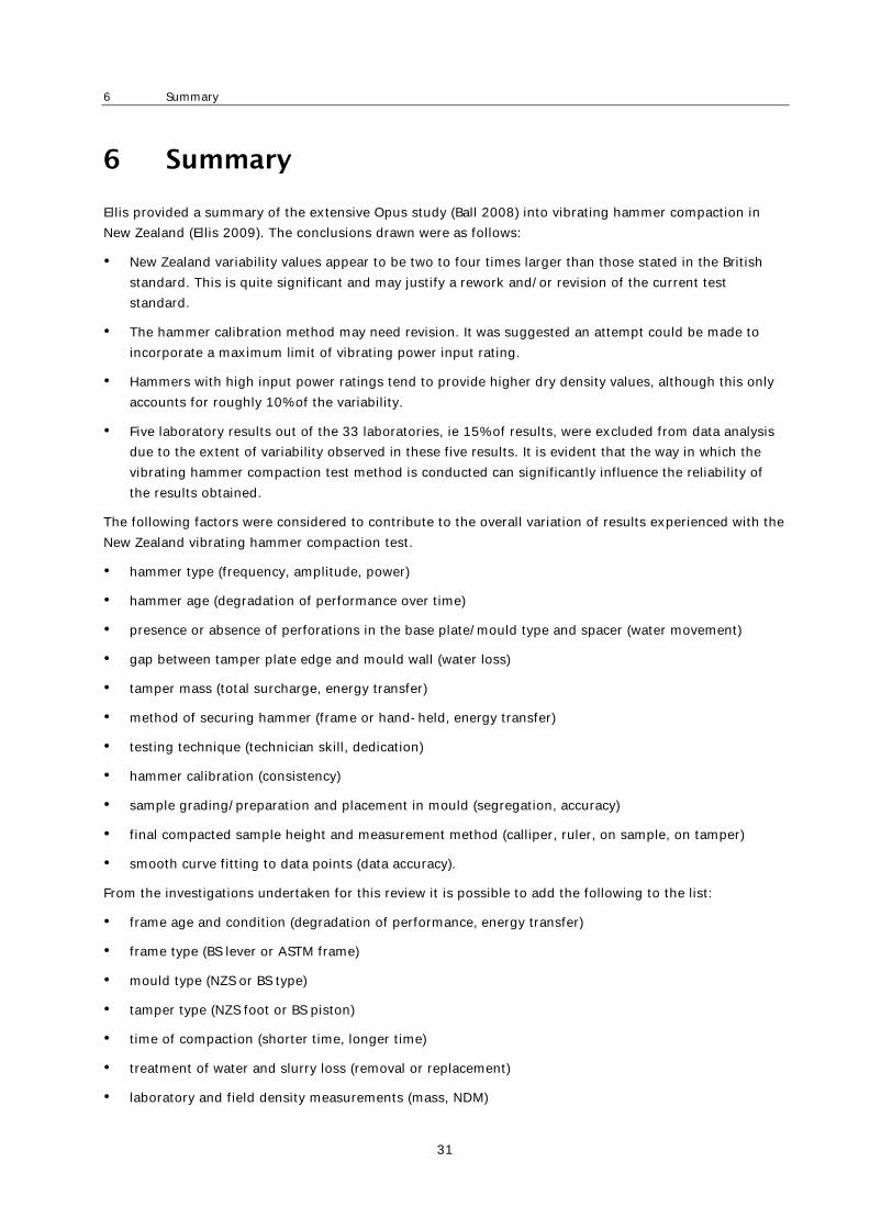
6 Summary
31
6 Summary
Ellis provided a summary of the extensive Opus study (Ball 2008) into vibrating hammer compaction in New Zealand (Ellis 2009). The conclusions drawn were as follows:
• New Zealand variability values appear to be two to four times larger than those stated in the British standard. This is quite significant and may justify a rework and/or revision of the current test standard.
• The hammer calibration method may need revision. It was suggested an attempt could be made to incorporate a maximum limit of vibrating power input rating.
• Hammers with high input power ratings tend to provide higher dry density values, although this only accounts for roughly 10% of the variability.
• Five laboratory results out of the 33 laboratories, ie 15% of results, were excluded from data analysis due to the extent of variability observed in these five results. It is evident that the way in which the vibrating hammer compaction test method is conducted can significantly influence the reliability of the results obtained.
The following factors were considered to contribute to the overall variation of results experienced with the New Zealand vibrating hammer compaction test.
• hammer type (frequency, amplitude, power)
• hammer age (degradation of performance over time)
• presence or absence of perforations in the base plate/mould type and spacer (water movement)
• gap between tamper plate edge and mould wall (water loss)
• tamper mass (total surcharge, energy transfer)
• method of securing hammer (frame or hand-held, energy transfer)
• testing technique (technician skill, dedication)
• hammer calibration (consistency)
• sample grading/preparation and placement in mould (segregation, accuracy)
• final compacted sample height and measurement method (calliper, ruler, on sample, on tamper)
• smooth curve fitting to data points (data accuracy).
From the investigations undertaken for this review it is possible to add the following to the list:
• frame age and condition (degradation of performance, energy transfer)
• frame type (BS lever or ASTM frame)
• mould type (NZS or BS type)
• tamper type (NZS foot or BS piston)
• time of compaction (shorter time, longer time)
• treatment of water and slurry loss (removal or replacement)
• laboratory and field density measurements (mass, NDM)

Standardisation of laboratory compaction energies
32
• material properties (selection of compaction method)
• test not being performed in accordance with the New Zealand standard.
All of the evidence described in this report suggests there is enormous scope for variability in the New Zealand vibrating hammer compaction test and that scope for introduction of an alternative method, such as the vibrating table method or the gyratory compaction method, does exist. The characteristics of each method are summarised in table 6.1 below:
Table 6.1 Characteristics of the three main compaction methods
Characteristics Vibrating hammer Vibrating table Gyratory compactor
Cost Relatively low cost Moderate cost High cost
Ease of purchase Different suppliers necessary for hammer, frame, moulds
One supplier needed for all components
One supplier for all components
Ease of use Can be fiddly. Some experience useful
Some issues with movement of heavy surcharges and moulds
Very easy to use. Needs compressed air feed
Messy Can allow wet slurry to be expelled from mould. Has no effect on the equipment
Should remain relatively clean. Could affect equipment if enters mechanism
Should remain relatively clean. Leaking slurry can be difficult to clean and can damage equipment
Operator training Can be tricky. Not straightforward to obtain consistent results
Appears very straightforward Very straightforward
Consistent energy input Not necessarily. Appears very variable
Appears to be consistent Yes
Controllable energy input/compaction load
Equipment energy output, amplitude and frequency set by manufacturer, surcharge weight user adjustable
Equipment energy, frequency, sample surcharge user adjustable
Compaction load, gyration angle and frequency fully adjustable
Controllable compaction time
Yes Yes Yes
Compaction energy measurable
Possible Possible Yes. Indeed it is known precisely
Long term reliability Typically good but does wear out over time
Poor reputation for long term reliability which may or may not be better with new equipment
Typically good reputation
Correlation to field compaction
Widely used, but not necessarily good
Not known in New Zealand Not known in New Zealand but good correlations in USA
History of use in New Zealand
Significant history of use Limited/little history of use in New Zealand
Limited/moderate history of use in New Zealand
High degree of compaction Not necessarily Appears to achieve high degrees of compaction
Achieves high degrees of compaction
Damage to sample Yes. Particle degradation widely observed
Typically less damage Typically lower than other methods

6 Summary
33
Characteristics Vibrating hammer Vibrating table Gyratory compactor
Different mould sizes Yes. 152 and 300 mm Yes. Any size that will fit onto table top is possible
No. Only 150 mm with current equipment. No plans to develop larger mould
Sample ‘scalping’ required Yes, with 152 mm mould No, with 300 mm mould
No Yes
Different designs Yes. Many different hammers and frames available
Yes. Many different table designs available
Fewer suppliers. One supplier appears to be leader
Temperature/environmental control
Possible to use inside environmentally controlled cabinet
Would probably need environmentally controlled room
Would probably need environmentally controlled room
Local suppliers/service agents
Yes Not known Yes
Note: Green = good or advantageous characteristic; Orange = neutral or moderately disadvantageous characteristic; red = disadvantageous characteristic.

Standardisation of laboratory compaction energies
34
7 Recommendations for establishing standardised compaction energy
This project was initiated to examine the variability that exists with the vibrating hammer laboratory compaction testing as it currently exists in New Zealand, and then to consider how to standardise the compaction energy that is input into test samples, either by improvement of the existing method, or by introducing an alternative method. This general area has been extensively studied and reviewed and a review of that literature was undertaken.
Analysis of the literature and discussions with technicians in the sector permitted recommendations to be made for developing approaches that might improve upon the current situation.
In his summary of the large Opus investigation into laboratory vibrating hammer testing, Ellis (2009) made recommendations aimed at reducing the variability of the laboratory results as listed below:
Step 1: Establish an appropriate minimum dry density that is needed for an example aggregate to ensure adequate strength and performance in the pavement is achieved.
Step 2: Carry out repeatability trials using a single laboratory set up and a specifically chosen example aggregate. Compare against benchmark BS and ASTM variance values, should they exist. Explore the effect of different hammer models, mould type and other factors. Choose options with the least variation contribution and from there agree on a standardised hammer type, mould and technique, while ensuring data generated from chosen equipment and technique will produce appropriate MDD from step 1 above.
Step 3: Review and rewrite as appropriate the test methodology based on the findings above, providing an improved degree of prescriptive guidance.
Step 4: Verify the reproducibility by carrying out a new national proficiency test using the new methodology.
The gyratory compaction technique was not considered in either Ball (2008) or Ellis (2009), but the literature reviewed here suggests it is a technique that may well be worth further consideration. No NZS method currently exists for its application to the problem of aggregate compaction.
Two approaches may be taken to achieve the outcome of reducing compaction test result variability through the concept of standardising the compaction energy. The first is to substitute the vibrating hammer test for a new test adapted to the New Zealand context, such as the vibrating table test or the gyratory compactor test. The second approach is, as suggested by Ellis, to reassess the vibrating hammer test and tighten up on its contributing factors and details.
Some indication of costs for new and/or upgraded equipment suggests the gyratory compactor would be the most expensive, but the vibrating table and all the equipment required for the vibrating hammer test (hammer, frame, mould) would be in the region of US$20,000 each.
It is not clear at the current time if changing to either the vibrating table test or the gyratory compactor test would provide any practicable improvement to the current situation; this can only be determined with a rigorous testing programme and prescriptive standard.
Recommendations are as follows:
• Examine the ASTM and BS standard methods for the vibrating hammer and adopt them more closely where applicable.

7 Recommendations for establishing standardised compaction energy
35
• Instrument the vibrating hammer equipment to provide an understanding of the existing method and to enable its assessment, including what possible aspects and refinements to consider.
• To allow the effect of variables to be estimated and allow limits for these variables to be derived, develop a Matlab model based on the data obtained from the instrumented hammer.
• Compare the vibrating hammer, vibrating table and gyratory test methods side by side to obtain results from each method and determine if any of these methods offer improved compaction results and/or variability.
– Use two specific but differently sourced basecourse aggregate samples from diverse geological sources. They should be M/4 specified basecourses because the grading, history and typical test results will be previously understood.
– Use samples applied in new constructions so contemporary laboratory and field compaction results could be compared with those obtained by the new investigation.
– Use brand new equipment for each test. Clearly the vibrating table would be new as there are few, if any in New Zealand. Similarly the entire vibrating hammer system must be new, including the hammer, the frame and the moulds so the test comparisons all start from the same point. The type of frame would also need to be well considered. Perhaps the gyratory compactor might not need to be new, but any instrument chosen would need to be well serviced prior to use. Some judgement would be required regarding which equipment models should be used.
– Undertake an experimental design in order to investigate the test parameters that would be determined as being important to the test outcome, such as: compaction time; aggregate grading; surcharge weight; sample temperature and other possible variables. This may be a ruggedness test (eg ASTM E1169), but may be a more simply designed experiment.
– Recruit one operator to perform the tests. This operator would ideally be experienced in sample preparation and the management of the testing. Additionally, this operator would undergo remedial training in order to reinforce the current test standard method.
– Following assessment and determination of acceptable methodologies, recruit several further operators to perform the tests under exactly the same conditions and analyse their results for variability.
– Roll out the methods across New Zealand so they can be performed in different environments and the variability assessed.
– Investigate the 300 mm mould.
If, the above programme results in a decision to adopt a compaction method other than the vibrating hammer method then a new New Zealand standard would need to be derived. If the outcome is to continue with the vibrating hammer test, it is likely the current standard would need to be revised and tightened up. One example of such a revision is the calibration method, where there should be a range for compacted density rather than simply a minimum value.

Standardisation of laboratory compaction energies
36
8 References
Araya, AA (2011) Characterisation of unbound granular materials for pavements. MSc thesis. The Netherlands: Technical University of Delft.
Arcement, BJ and SG Wright (2001) Evaluation of laboratory compaction procedures for specification of densities for compacting fine sands. Center for Transportation research report 1874-1. Austin: University of Texas.
Ball, GFA (2008) New Zealand vibrating hammer compaction test interlaboratory study. Auckland: Opus International Consultants Ltd.
Bergeson, KC, M Jahren, M Wermager and D White (1998) Embankment quality. Phase I report. Iowa State University.
Bishop, AW and GE Green (1965) The influence of end restraint on the compression strength of a cohesionless soil. Geotechnique 15: 243–266.
Black, PM (2009) Geologic inventory of North Island aggregate resources: influences on engineering
materials properties. University of Auckland.
Brandl, H (2001) The importance of optimum compaction of soil and other granular material. In
Geotechnics for roads, rail tracks and earth stuctures. AG Correia and H Brandl (Eds). Lisse, The Netherlands: AA Balkema Publishers.
Budhu, M (2006) Soil mechanics and foundations. 2nd ed. New York: John Wiley and Sons. 656pp.
Cetin, A, Z Kaya, B Cetin and AH Aydilek (2014) Influence of laboratory compaction method on mechanical
and hydraulic characteristics of unbound granular base materials. Road Materials and Pavement Design 15, no.1: 220–235.
Christopher, BR, C Schwartz and R Boudreau (2006) Geotechnical aspects of pavements. National Highway Institute.
Chilukwa, NN (2013) Vibratory hammer compaction of granular materials. ME thesis, South Africa: University of Stellenbosch.
Dodd, TAH and RJ Dunlop (1971) An improved kneading compaction machine. Christchurch: University of Canterbury.
Drnevich, V, A Evans and A Prochaska (2007) A study of effective soil compaction control of granular soils. Indiana: Purdue University.
Dunlap, WA (1966) Deformation characteristics of granular materials subjected to repetitive loading. Texas Transportation Institute.
Ellis, J (2009) New Zealand vibrating hammer compaction test interlaboratory study. CETANZ.
Farrar, JA (2000) Compaction control of coarse grained aggregates. International Center for Aggregates
Research 8th Annual Symposium: Aggregates-Asphalt Concrete, Bases and Fines, Denver CO.
Felt, EJ (1968) Laboratory methods of compacting granular soils. ASTM special technical publication 239.
Forssblad, L (1981) Compaction meter on vibrating rollers for improved compaction control. In Proceedings of International Conference on Compaction, Paris, 1981.

8 References
37
Frobel, T and S Moulding (2006) Errors in the vibrating hammer compaction test. In Proceedings of Civil
Engineering Laboratories Conference, 2006.
Hausmann, MR (1990) Engineering principles of ground modification. Sydney: McGraw-Hill.
Head, KH (1980) Manual of soil laboratory testing. Vol 1. Soil classification and compaction tests. Pentech Press.
Henderson, R, P Herrington P, J Patrick, P Kathirgamanathan and S Cook (2011) Analysis of particle orientation in compacted unbound aggregate. Road Materials and Pavement Design 12, no.1: 2011.
Hilf, JW (1991) Compacted fill. Pp 249–316 in Foundation engineering handbook. 2nd ed. HY Fang (Ed). New York: Chapman and Hall.
Hoover, JM, S Kumar and TW Best (1970) Degradation control of crushed stone basecourse mixes during laboratory compaction. Highways research record 301: 1970.
IHS Markit (2010) ASTM International approves vibrating hammer test – ASTM D7382.
Johnson, AW and JR Sallberg (1960) Factors that influence field compaction of soils. Highway Research
Board Bulletin 272: 1960.
Karan, P, DJ Wilson and TJ Larkin (2014) Methods of compacting basecourse aggregate for RLT testing. IPENZ Transportation group conference, Wellington, 2014.
Karan, P, TJ Larkin and DJ Wilson (2017) Vibratory compaction of basecourse aggregates. University of Auckland.
Kelfkens, RWC (2008) Vibratory hammer compaction of bitumen stabilised material. MSc thesis. University of Stellenbosch.
Kosmatka, SH, B Kerkoff and WC Panarese (2002) Design and control of concrete mixtures. 14th ed. Stokie, Illinois: Portland Cement Association. 358pp.
Lambert, N, K Denny, B Sukumaran and Y Mehta (2009) Evaluation of the compaction characteristics of unbound material using the superpave gyratory compactor. GeoHunan International Conference,
Asphalt Material Characterisation, Accelerated Testing and Highway Management. 2009.
Lowe, JS, DJ Wilson and PM Black (2010) The proficiency of sand equivalent and methylene blue (clay index) test methods for determining the deleterious mineral content of weakly metamorphosed sedimentary rock. Road and Transport Research 19, no.4: 14.
Luxford, NS (1975) Compaction test for aggregate studies. Wellington: National Roads Board.
New Zealand Institute of Highway Technology (NZIHT) (2000) Hiway 6011 – pavement design. New Plymouth: NZIHT.
Parsons, AW (1992) Compaction of soils and granular materials: a review of research preformed at the
transport research laboratory. London: HMSO.
Patrick, JE and D Alabaster (1998) Pavement density. Transfund NZ research report 100.
Pike, DC (1972) Compactability of graded aggregates, I. Standard laboratory tests. Crowthorne, Berkshire: Transport and Road Research Laboratory.
Ping, WV, G Xing, M Leonard and Z Yang (2003) Evaluation of laboratory compaction techniques for
simulation of field compaction (phase II). Tallahassee: Florida State University.
Preston, JN (1991) The design of bituminous concrete mixes. PhD thesis. University of Nottingham, UK.

Standardisation of laboratory compaction energies
38
Prochaska, AB and VP Drnevich (2005) One-point vibrating hammer compaction test for granular soils. In Proceedings of ASCE Geo-frontiers Conference, Austin, 2005.
Prochaska, AB, VP Drnevich, D Kim and KEA Sommer (2005) A vibrating hammer compaction test for granular soils and dense graded aggregates. Annual meeting of the Transportation Research Board, 2005.
Proctor, RR (1933) Fundamental principles of soil compaction. Engineering News-Record 111, no.9: 245–248.
Ramadan, A (2012) Soil compaction. Accessed 3 September 2017. www.slideshare.net/ENG_ANAS87/5-compaction.
Roberts, FL (1976) An evaluation of a proposed test method for determining the maximum dry density of dense graded aggregate. Journal of Testing and Evaluation 4, no.5: 303–312.
Shahin, AW (2010) Investigation of the variability in the results of the New Zealand vibrating hammer
compaction test. ME thesis. University of Auckland, New Zealand.
Sherwood, PT (1970) The reproducibility of the results of soil classification and compaction tests.
Strohm, WE, EH Nettles and CC Calhoun (1967) A study of drainage characteristics of basecourse materials. Highway research record 203.
Transport and Road Research Laboratory (TRRL) (1987) Contractor report no.1. The percentage refusal
density test. US Dept of Transport.
White, D, KL Bergeson, C Jahren and M Wermager (1999) Embankment quality phase II report. Iowa DOT project TR-401.
Yaghoubi, E, MM Disfani, A Arulrajah and J Kodikara (2017) Impact of compaction method on mechanical characteristics of unbound granular recycled materials. Road Materials and Pavement Design: 1–23.
8.1 Standards referenced ASTM D4013. Preparation of test specimens of bituminous mixtures by means of gyratory shear
compactor. American Society for Testing and Materials.
ASTM D-1557/AASHTO-T180:2009. Standard test methods for laboratory compaction characteristics of soil using modified effort (56,000 ft-lbf/ft3 (2,700 kN-m/m3)). American Society for Testing and Materials.
ASTM D-1561. Preparation of bituminous mixture test specimens by means of California kneading compactor. American Society for Testing and Materials.
ASTM D4253-16. Standard test methods for maximum index density and unit weight of soils using a vibratory table. American Society for Testing and Materials.
ASTM D7382-07:2008. Standard test methods for determination of maximum dry unit weight and water contest range for effective compaction of granular soils using a vibrating hammer. American Society for Testing and Materials.
ASTM E177-14:2014. Standard practice for use of the terms precision and bias in ASTM test methods. American Society for Testing and Materials.
ASTM E1169-14:2014. Standard practice for conducting ruggedness tests. American Society for Testing and Materials.

8 References
39
BS 5835-1: 1980. Recommendation for testing of aggregates part 1: Compactibility test for graded aggregates. British Standards Institution.
BS EN 1377-1:2016. Methods of test for soils for civil engineering purposes –-part 1: General requirements and sample preparation. British Standards Institution.
BS EN 13286-4:2003. Unbound and hydraulically bound mixtures – part 4: Test methods for laboratory reference density and water content – vibrating hammer. British Standards Institution.
BS EN 13286-5:2003. Unbound and hydraulically bound mixtures – part 5: Test methods for laboratory reference density and water content – vibrating table. British Standards Institution.
M/04:2006. Specification for basecourse aggregate, Transit New Zealand.
NZS 4402.4.1.2:1986. Methods of testing soils for civil engineering purposes – Soil compaction tests – Determination of the dry density/water content relationship – Test 4.1.2 New Zealand heavy compaction test. Standards New Zealand.
NZS 4402.4.1.3:1986. Methods of testing soils for civil engineering purposes - Soil compaction tests – Determination of the dry density/water content relationship – Test 4.1.3 New Zealand vibrating hammer compaction test. Standards New Zealand.
TMH1:1986. Technical methods for highways: Standard methods of testing road construction materials. 2nd ed. Pretoria, South Africa: Committee of State Road Authorities.
TNZ B/02:2005. Specification for construction of unbound granular pavement layers. Transit New Zealand.
TxDOT:1993. Manual of testing procedures. Test method Tx-114-E. Texas Department of Transport, 18.