
Research Paper SEISMIC RESPONSE OF RC BUILDING BY CONSIDERING SOIL STRUCTURE INTERACTION€¦ ·...
13
SEISMIC RESPONSE OF RC BUILDING BY CONSIDERING SOIL STRUCTURE INTERACTION Jinu Mary Mathew 1 *, Cinitha A 2 , Umesha P K 2 , Nagesh R Iyer 2 and Eapen Sakaria 3 This study is to investigate the effect of earthquake motions on the response of a three- dimensional nine storey reinforced concrete structure with and without considering soil-structure interaction. Numerical modelling of such analysis requires the determination of the nonlinear properties of each component in the structure, quantified by strength and deformation capacities. Nine storey RC building asymmetric in plan, height below 45 m, located in seismic zone III designed as per IS 456:2000 and IS1893:2002 and detailed as per IS13920:1993. Properties of nonlinear hinge properties are computed as per FEMA-356 and ATC 40 guidelines. Pushover analysis is carried out in X- and Y- directions using user-defined nonlinear hinge properties. The analysis has been carried out for the three different cases: (1) Fixed base without considering soil structure interaction (SSI), (2) Flexible base by considering SSI in hard soil condition, and (3) Flexible base by considering SSI in soft soil condition. It was found that SSI can affect the seismic performance of building in terms of seismic force demands and deformations. From the capacity curve, it is observed that SSI effects are significant for soft soil conditions and negligible for stiff soil conditions. 1 Saintgits College of Engineering, Kottayam. 2 CSIR-Structural Engineering Research Centre,Chennai-113. 3 Saintgits College of Engineering, Kottayam. *Corresponding author:Jinu Mary Mathew [email protected] ISSN 2319 – 6009 www.ijscer.com Vol. 3, No. 1, February 2014 © 2014 IJSCER. All Rights Reserved Int. J. Struct. & Civil Engg. Res. 2014 Research Paper Keywords: Soil structure interaction, Push-over analysis, Plastic hinge, Seismic performance INTRODUCTION Structural failures during Bhuj (2001) and Sikkim (2011) earthquakes demonstrated the importance of Soil-Structure Interaction (SSI) effects and its consideration to avoid failure and ensure safety. The possible bedrock movements during earthquakes intensify the dynamic effects of site and changes the structural response. Thus, the influence of foundation flexibility is so much important. The soil-structure interaction is an important issue, especially for stiff and massive structures constructed on the relatively soft ground, which may alter the dynamic characteristics of the structural response significantly. Past experiences showed that the soil under foundation can alter dynamic behavior of structure. The dynamic response of structures depends upon soil nature located under foundation, so neglecting of soil-structure
Transcript of Research Paper SEISMIC RESPONSE OF RC BUILDING BY CONSIDERING SOIL STRUCTURE INTERACTION€¦ ·...

160
Int. J. Struct. & Civil Engg. Res. 2014 Jinu Mary Mathew et al., 2014
SEISMIC RESPONSE OF RC BUILDING BY
CONSIDERING SOIL STRUCTURE INTERACTION
Jinu Mary Mathew1*, Cinitha A2, Umesha P K2, Nagesh R Iyer2 and Eapen Sakaria3
This study is to investigate the effect of earthquake motions on the response of a three-dimensional nine storey reinforced concrete structure with and without considering soil-structureinteraction. Numerical modelling of such analysis requires the determination of the nonlinearproperties of each component in the structure, quantified by strength and deformation capacities.Nine storey RC building asymmetric in plan, height below 45 m, located in seismic zone IIIdesigned as per IS 456:2000 and IS1893:2002 and detailed as per IS13920:1993. Properties ofnonlinear hinge properties are computed as per FEMA-356 and ATC 40 guidelines. Pushoveranalysis is carried out in X- and Y- directions using user-defined nonlinear hinge properties. Theanalysis has been carried out for the three different cases: (1) Fixed base without consideringsoil structure interaction (SSI), (2) Flexible base by considering SSI in hard soil condition, and(3) Flexible base by considering SSI in soft soil condition. It was found that SSI can affect theseismic performance of building in terms of seismic force demands and deformations. Fromthe capacity curve, it is observed that SSI effects are significant for soft soil conditions andnegligible for stiff soil conditions.
1 Saintgits College of Engineering, Kottayam.
2 CSIR-Structural Engineering Research Centre,Chennai-113.
3 Saintgits College of Engineering, Kottayam.
*Corresponding author:Jinu Mary Mathew � [email protected]
ISSN 2319 – 6009 www.ijscer.com
Vol. 3, No. 1, February 2014
© 2014 IJSCER. All Rights Reserved
Int. J. Struct. & Civil Engg. Res. 2014
Research Paper
Keywords: Soil structure interaction, Push-over analysis, Plastic hinge, Seismic performance
INTRODUCTION
Structural failures during Bhuj (2001) andSikkim (2011) earthquakes demonstrated theimportance of Soil-Structure Interaction (SSI)effects and its consideration to avoid failureand ensure safety. The possible bedrockmovements during earthquakes intensify thedynamic effects of site and changes thestructural response. Thus, the influence offoundation flexibility is so much important. The
soil-structure interaction is an important issue,especially for stiff and massive structuresconstructed on the relatively soft ground, whichmay alter the dynamic characteristics of thestructural response significantly. Pastexperiences showed that the soil underfoundation can alter dynamic behavior ofstructure. The dynamic response of structuresdepends upon soil nature located underfoundation, so neglecting of soil-structure

161
Int. J. Struct. & Civil Engg. Res. 2014 Jinu Mary Mathew et al., 2014
interaction is unsafe. During an earthquake,the load and deformation characteristic of thestructural and geotechnical (soil) componentsof the foundations of structures can effect, andin some cases dominate, seismic responseand overall performance. Understanding thisimportance structural engineers/researchershas included the foundation strength andstiffness in seismic analysis models. Themodelling of soil and structural parts offoundations inherently accounts the interactionof soil and structure.
In soil structure interaction the appropriatemodelling of the flux of energy from the soil tothe structure, and then back from the structureto the soil is accounted and the process iscalled SSI. Stewart et al. (1999) indicates thatthere is a high correlation between thelengthening ratio of the structural period dueto the flexibility of the foundation and structureto soil stiffness ratio. As a general trend whenthe structure is stiff and underlying soil is softthe soil structure effect gets important, on theother hand as the structural period gets longerand stiffness of the soil under the structure getshigher soil structure interaction losses itsimportance. The response to earthquakemotion of a structure situated on a deformablesoil differs from structure supported on a rigidfoundation. The ground motion recorded at thebase of the structure differs from the recordswithout building. The dynamic characteristicsuch as vibration modes and frequencies verymuch correlate with the induced changes indynamic characteristic of soil during seismicexcitation which shows the significance of soilstructure interaction on the response of thestructure to earthquake motion that isinvestigated in the present study. Boonyapinyo
et al. (2008) studied the seismic performanceevaluation of reinforced-concrete buildings bystatic pushover and nonlinear dynamicanalyses. Evaluated the seismic performanceof building by nonlinear static analyses(pushover analysis and modal pushoveranalysis) and nonlinear time history analysis.Hayashi et al. (2004) pointed out that thedamage reduction effects by soil-structureinteraction greatly depend on the ground motioncharacteristics, number of stories and horizontalcapacity of earthquake resistance of buildings.They brought out the importance of soil-structureinteraction including nonlinear phenomena suchas base mat uplift to evaluate the earthquakedamage of buildings properly. The mainobjective of this paper is to better understandthe soil structure interaction analysis andperformance of a nine- storey RC buildingsituated in soft soil of seismic zone III. For thispurpose the three-dimensional (3D) framestructures is analyzed by using SAP 2000 forthree conditions: (1) Fixed base withoutconsidering SSI, (2) Flexible base byconsidering SSI in hard soil condition; and (3)Flexible base by considering SSI in soft soilcondition. Equivalent springs under raftfoundation are used to simulate SSI in this study
NINE-STOREY REINFORCED
CONCRETE FRAME
BUILDING
Building Details
A nine-storey RC building located inTrivandrum, Kerala designed for gravity andearthquake loads is studied. The rectangularplan of building is 15.31 m by 7.82 m. The storyheight is 2.85 m with a total height of 27.15 m.The structural system is asymmetrical and plan

162
Int. J. Struct. & Civil Engg. Res. 2014 Jinu Mary Mathew et al., 2014
layout is shown in Figure 1. The frames ofbuilding were designed as gravity frames. Thethickness of floor slab is taken as 0.15 m androof slab is taken as 0.10 m, 0.11 m and 0.25m depending upon whether the slab is balcony,roof, sunken slab, respectively.
All columns and beam dimensions are givenin Tables 1 and 2, and building is supportedon raft slab of thickness 0.40 m. It is designedfor a soil bearing capacity of 120 kN/m2. Thecylinder compressive strengths of concretecolumns and beams are 30 MPa. Theexpected yield strength of steel deformed barsis 500 MPa.
Plastic Hinge Model
Seismic response of reinforced concrete 3Dmoment frame is modelled through nonlinearelement representations of column, beam andbeam column joints. Nonlinear elementformulations for reinforced concrete members
Figure 1: Plan of the Building
Table 1: Dimension of Components of the Building-Beams
Reinforcement
Beam Dimension Section Fe Fc Top Bottom Clear
No. (MPa) (MPa) Reinf Reinf Stirrups Cover
(mm)
B1 200 x 500 G1 500 30 2Y20 2Y16, 2Y25 Y8-100 30
B2 200 x 600 G2 500 30 2Y20, 3Y25 3Y25 Y8-100 30
B12 200 x 500 G10 500 30 5Y25 2Y25, 2Y20 Y8-100 30
B16 200 x 400 G14 500 30 2Y16 2Y16 Y8-100 30
B22 200 x 500 G19 500 30 2Y25, 1Y20 3Y25 Y8-100 30
B23 200 x 500 G20 500 30 2Y16, 1Y12 3Y16 Y8-100 30
B30 200 x 600 G26 500 30 2Y20, 2Y25 2Y20, 1Y25 Y8-100 30
B31 200 x 500 G27 500 30 2Y20, 2Y25 2Y20 Y8-100 30
B31a 200 x 600 G28 500 30 2Y20, 1Y25 3Y16 Y8-100 30
B32 200 x 400 G29 500 30 2Y16 4Y16 Y8-150 30
B33 200 x 500 G30 500 30 3Y16 2Y16, 1Y12 Y8-150 30
B34 200 x 600 G28 500 30 2Y20, 1Y25 3Y16 Y8-100 30
B48 200 x 600 G39 500 30 2Y25, 1Y20 2Y25 Y8-100 30

163
Int. J. Struct. & Civil Engg. Res. 2014 Jinu Mary Mathew et al., 2014
Table 2: Dimension of Components of the Building-Columns
Column Dimension Section No. Fe (MPa) Fc (MPa) Long.Reinf Stirrups Clear Cover (mm)
Ground Floor
C1 300 x 800 C1 500 30 14Y25 Y8-150 40
C4 300 x 1000 C4 500 30 18Y25 Y8-150 40
C6 300 x 900 C6 500 30 20Y25 Y8-150 40
C9 300 x 1200 C9 500 30 22Y25 Y8-150 40
C10 250 x 1000 C10 500 30 24Y25 Y8-250 40
C11 300 x 900 C11 500 30 24Y25 Y8-150 40
C12 300 x 1200 C12 500 30 18Y25 Y8-150 40
C13 250 x 800 C13 500 30 14Y25 Y8-150 40
C16 300 x 1400 C16 500 30 24Y25 Y8-150 40
Typical Floor
C1 200 x 800 C17 500 30 12Y25 Y8-150 40
C4 200 x 1000 C20 500 30 16Y25 Y8-150 40
C6 300 x 900 C6 500 30 20Y25 Y8-150 40
C9 200 x 1200 C24 500 30 20Y25 Y8-150 40
C10 250 x 1000 C25 500 30 22Y25 Y8-250 40
C11 300 x 900 C11 500 30 24Y25 Y8-150 40
C12 200 x 1200 C26 500 30 16Y25 Y8-150 40
C13 250 x 800 C27 500 30 12Y25 Y8-150 40
C16 200 x 1400 C30 500 30 22Y25 Y8-150 40
range from 3D continuum finite element modelsto lumped plasticity concentrated hingemodels. Lumped plasticity models consist ofelastic elements with concentrated plastichinges at each end. Concentrated plastichinges are represented by rotational springswith back bone and cyclic deteriorationproperties that have been calibrated to results
from experimental studies [FEMA 356]. Plastichinge form at the maximum moments regionsof RC members. The accurate assessment ofplastic hinge length is important in relating thestructural level response to member levelresponse. The length of plastic hinge dependson many factors: (1) level of axial load (2)moment gradient, (3) level of shear stress in

164
Int. J. Struct. & Civil Engg. Res. 2014 Jinu Mary Mathew et al., 2014
plastic region, (4) mechanical properties oflongitudinal and transverse reinforcement, (5)concrete strength, (6) level of confinement andits effectiveness in potential hinge region. Forthe present study length of plastic hinge istaken as 0.5 H, where H is the depth of crosssection.
Stress Strain Relation for ConfinedConcrete
In order to define moment-curvature relationto simulate the onset of damage, the stress-strain model of confined concrete and typicalsteel stress-strain model with strain hardeningis essential. In this study modified mander’sconfined concrete model as per CENEurocode 8 is used. A comparison of confinedand unconfined stress-strain relation observedis shown in Figure 2.
which include distribution of steel including
spacing of longitudinal and lateral steel,
amount of lateral steel, type of anchorage and
grade of concrete. Under estimation of ultimate
curvature may result brittle shear failure even
the members are well detailed for ductile
flexural behavior. In this study, nonlinear static
analyses are carried out using user-defined
plastic hinge properties. Definition of user-
defined hinge properties requires moment-
curvature characteristics of each element. The
obtained moment-curvature behavior of beams
and columns are shown in Figures 3-5.
Figure 2: Comparison of Stress VsStrain Relation Of Confined And
Unconfined Concrete
Moment – Curvature Relationship
The moment curvature relations are essentialto model nonlinear behavior of structure andmembers. The ultimate deformation capacityof a member depends on the ultimatecurvature and the plastic hinge length (Inel etal., 2006). The conservative estimation ofultimate curvature depends on several factors
Figure 3: Moment Vs Curvaturefor Beams
Figure 4: Moment vs Curvaturefor Ground floor Columns

165
Int. J. Struct. & Civil Engg. Res. 2014 Jinu Mary Mathew et al., 2014
The moment-curvature analyzes are carriedout considering section properties and aconstant axial load on the structural element.In development of user-defined hinges forcolumns, the maximum load due to severalpossible combinations considered need to begiven as input in SAP2000. Following, thecalculation of the ultimate curvature capacityof an element, acceptance criteria are definedand labelled as IO, LS and CP. The typicaluser-defined (moment-curvature) hingeproperties for beams and columns (M2-M3and PMM hinges in SAP 2000) used for theanalysis are shown in Figures 6 and 7,respectively. The values of these performancelevels can be obtained from the test results inthe absence of the test data, and the valuesrecommended by ATC-40. The acceptancecriteria for performance within the damagecontrol performance range are obtained byinterpolating the acceptance criteria providedfor the IO and the LS structural performancelevels. Acceptance Criteria for performancewithin the limited safety structural performancerange are obtained by interpolating the
acceptance criteria provided for the life safetyand the collapse prevention structuralperformance levels. A target performance isdefined by a typical value of roof drift, as wellas limiting values of deformation of thestructural elements. To determine whether abuilding meets performance objectives,response quantities from the pushover analysisshould be considered with each of theperformance levels.
Soil Structure Interaction
According to the seismic improvement ofcurrent structure provision, the members ofstructure and foundation must be modelled
Figure 5: Moment vs Curvaturefor Typical Floor Columns
Figure 6: Typical user-definedMoment-rotation Hinge Properties
(M2-M3)-Beams
Figure 7: Moment vs. RotationCurves (P-M-M) - Columns
166
Int. J. Struct. & Civil Engg. Res. 2014 Jinu Mary Mathew et al., 2014
together in unified model to consider soil-structure interaction. In this study twoorthogonal springs, a vertical spring and threerotational springs were used in main directionof structures to simulate soil structureinteraction. The stiffness of springs areestimated using Richart and Lysmer modeland incorporated in the analysis.
Foundation Model
Behavior of foundation components andeffects of soil-structure interaction wereinvestigated. Soil-structure interaction can leadto modification of building response. Soilflexibility results in period elongation anddamping increase. The main relevant impactsare to modify the overall lateral displacementand to provide additional flexibility at the baselevel that may relieve inelastic deformationdemands in the superstructure. In this study,the stiffness of springs are estimated usingRichart and Lysmer model which can berepresented by a series of 3 translational and3 rotational springs. The soil is treated as anisotropic, homogenous and elastic half spacemedium. For linear analysis, the unit weight ofsoil (γ), shear wave velocity (Vs) and Poissonratio (υ) are the inputs. Two scenarios wereassumed for the soil deposit used in the
present study, namely: Type I corresponding to“Rock or hard soil”; Type III corresponding to“soft soil” in accordance with the siteclassification of the IS 1893(Part 1): 2002. Table3 lists the properties assigned for these two soilclasses in the current study from the rangesspecified by ATC 40. The study primarilyattempts to see the effect of soil-structureinteraction on buildings resting on differenttypes of non-cohesive soil, viz., soft and rock.
Richart et al. (1970) idealized thefoundation as a lumped mass supported onsoil which is idealized as frequencyindependent springs which he described interms of soil parameter dynamic shearmodulus of shear wave velocity of the soil.Table 3 along with Table 4 shows the differentvalues of spring as per Richart and Lysmer. Inwhich, G = dynamic shear modulus of soil andis given by; G = ρVs2; υ = Poisson’s ratio ofthe soil; ρ = mass density of the soil; K =equivalent spring stiffness of the soil; r =equivalent radius of a circular foundation; L =length of the foundation; and B = width of thefoundation.
To examine the dynamic behavior whileconsidering the effect of soil-structureinteraction, building frames of nine storey was
Table 3: Soil Parameters Assigned For Type I and Type III
Description Type I Type III
Unit Weight γ 2563.00 kg/m3 1522.00 kg/m3
Mass density of soil ρ = γ /g 261.26 N/m3 155.15 N/m3
Shear wave velocity Vs 1220.00 m/s 150.00 m/s
Shear Modulus G = ρVs2 388859.00 kN/m2 3491.00 kN/m2
Poisson’s Ratio υ 0.25 0.50

167
Int. J. Struct. & Civil Engg. Res. 2014 Jinu Mary Mathew et al., 2014
idealized as 3D space frames using standardbeam element at each node. Slabs at differentstorey level were modelled with shell elementswith consideration of adequate thickness. Thestorey height of the building frames isconsidered as 2.85 m. The gravity loadsassigned to the building was seismic weightof structural components, including the beamsand columns and the reinforced concreteslabs. The weight of the non-structuralcomponents (e.g., Brick partitions, Plastering,floor finishing, etc.) in addition to the live loadare also considered. Since the slabs were notmodelled explicitly, their weight and the liveload they carry were included in the structuralmodel by distributing its reaction on thesupporting beams.
PUSH OVER ANALYSISAmongst the natural hazards, earthquakeshave the potential for causing the greatestdamages. Since earthquake forces arerandom in nature and unpredictable, theengineering tools need to be improved foranalyzing structures under the action of theseforces. Earthquake loads are to be carefullymodelled so as to assess the real behavior ofstructure with a clear understanding thatdamage is expected but it should be regulated.In this context pushover analysis which is aniterative procedure is looked upon as analternative for the conventional analysisprocedures. Pushover analysis of multi-storyRCC framed buildings subjected to increasinglateral forces is carried out until the pre-setperformance level (target displacement) is
Table 4: Values of Soil Springs as Per Richart and Lysmer (1970) Model
Direction Spring Value Equivalent Radius Remarks
Vertical 4
1z
z
GrK
z
LBr
This is in vertical Z direction
Horizontal
32 1
7 8x
x
GrK
x
LBr
This induce sliding in horizontal X or Y Direction
Rocking
38
3 1x
x
GrK
4 3
3x
LBr
This produces rocking about Y axis
Rocking
38
3 1y
y
GrK
4 3
3y
LBr
This produces rocking about X axis
Twisting
316
3z
GrK
4 3 3
6z
LB BLr
This produces twisting about vertical Z axis

168
Int. J. Struct. & Civil Engg. Res. 2014 Jinu Mary Mathew et al., 2014
reached. The promise of Performance-BasedSeismic Engineering (PBSE) is to producestructures with predictable seismicperformance.
The recent advent of performance baseddesign has brought the non linear static pushover analysis procedure to the forefront.Pushover analysis is a static non linearprocedure in which the magnitude of thestructural loading along the lateral direction ofthe structure is incrementally increased inaccordance with a certain pre-defined pattern.It is generally assumed that the behavior of thestructure is controlled by its fundamental modeand the predefined pattern is expressed eitherin terms of story shear or in terms offundamental mode shape. Push overprocedure is gaining popularity during the lastfew years as appropriate analytical tools arenow available (SAP-2000, ETABS).
In this study SAP 2000 version 14 is used.Building is modelled using the materials M30concrete and Fe500 Steel and assigned allthe beams and columns including with theirreinforcement, all loads (dead load, live load,and earthquake load) and user defined hinges.Eight sets of analysis were carried out, for acombination with and without considering SSIfor hard and soft soil in both X- and Y- direction.Four different models were created for twodifferent soil conditions. Figure 8 shows thebuilding with fixed base model and Figure 9shows building by considering SSI effect. TheSSI effect are modelled for 1) fixed base andflexible base for soft soil in X- direction, 2) fixedbase and flexible base for soft soil in Y -direction, 3) fixed base and flexible base forhard soil in X- direction, 4) fixed base andflexible base for hard soil in Y- direction.
Figure 8: Building with Fixed Base
Figure 9: Building with Flexible Base
169
Int. J. Struct. & Civil Engg. Res. 2014 Jinu Mary Mathew et al., 2014
RESULTS AND DISCUSSION
In the present study, user defined stress- straincurve based on CEN Eurocode-8 is adoptedand incorporated in SAP2000. Thepercentage variation of stress and strain forconfined concrete is found to be 10-20% and237-266%, respectively compared tounconfined concrete.
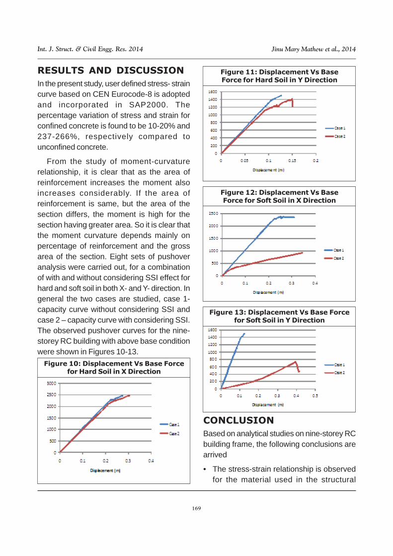
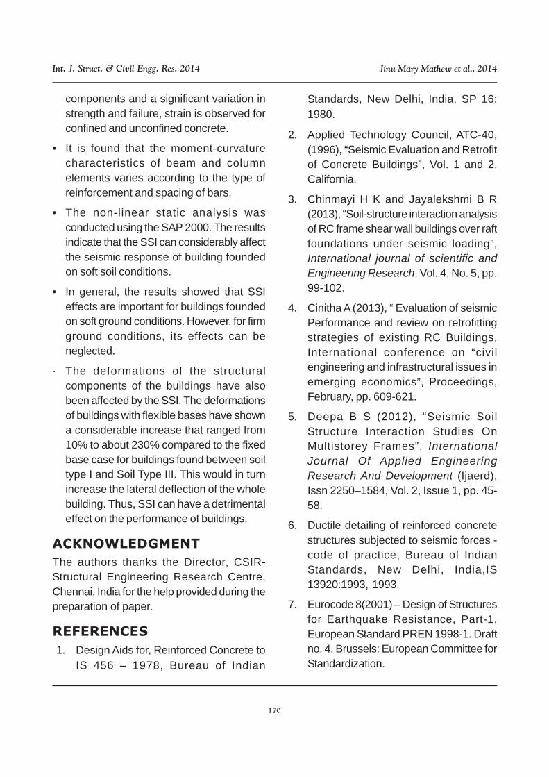
From the study of moment-curvaturerelationship, it is clear that as the area ofreinforcement increases the moment alsoincreases considerably. If the area ofreinforcement is same, but the area of thesection differs, the moment is high for thesection having greater area. So it is clear thatthe moment curvature depends mainly onpercentage of reinforcement and the grossarea of the section. Eight sets of pushoveranalysis were carried out, for a combinationof with and without considering SSI effect forhard and soft soil in both X- and Y- direction. Ingeneral the two cases are studied, case 1-capacity curve without considering SSI andcase 2 – capacity curve with considering SSI.The observed pushover curves for the nine-storey RC building with above base conditionwere shown in Figures 10-13.
Figure 10: Displacement Vs Base Forcefor Hard Soil in X Direction
Figure 11: Displacement Vs BaseForce for Hard Soil in Y Direction
Figure 12: Displacement Vs BaseForce for Soft Soil in X Direction
Figure 13: Displacement Vs Base Forcefor Soft Soil in Y Direction
CONCLUSION
Based on analytical studies on nine-storey RCbuilding frame, the following conclusions arearrived
• The stress-strain relationship is observedfor the material used in the structural
170
Int. J. Struct. & Civil Engg. Res. 2014 Jinu Mary Mathew et al., 2014
components and a significant variation instrength and failure, strain is observed forconfined and unconfined concrete.
• It is found that the moment-curvaturecharacteristics of beam and columnelements varies according to the type ofreinforcement and spacing of bars.
• The non-linear static analysis wasconducted using the SAP 2000. The resultsindicate that the SSI can considerably affectthe seismic response of building foundedon soft soil conditions.
• In general, the results showed that SSIeffects are important for buildings foundedon soft ground conditions. However, for firmground conditions, its effects can beneglected.
· The deformations of the structuralcomponents of the buildings have alsobeen affected by the SSI. The deformationsof buildings with flexible bases have showna considerable increase that ranged from10% to about 230% compared to the fixedbase case for buildings found between soiltype I and Soil Type III. This would in turnincrease the lateral deflection of the wholebuilding. Thus, SSI can have a detrimentaleffect on the performance of buildings.
ACKNOWLEDGMENT
The authors thanks the Director, CSIR-Structural Engineering Research Centre,Chennai, India for the help provided during thepreparation of paper.
REFERENCES
1. Design Aids for, Reinforced Concrete toIS 456 – 1978, Bureau of Indian
Standards, New Delhi, India, SP 16:1980.
2. Applied Technology Council, ATC-40,(1996), “Seismic Evaluation and Retrofitof Concrete Buildings”, Vol. 1 and 2,California.
3. Chinmayi H K and Jayalekshmi B R(2013), “Soil-structure interaction analysisof RC frame shear wall buildings over raftfoundations under seismic loading”,International journal of scientific andEngineering Research, Vol. 4, No. 5, pp.99-102.
4. Cinitha A (2013), “ Evaluation of seismicPerformance and review on retrofittingstrategies of existing RC Buildings,International conference on “civilengineering and infrastructural issues inemerging economics”, Proceedings,February, pp. 609-621.
5. Deepa B S (2012), “Seismic SoilStructure Interaction Studies OnMultistorey Frames”, InternationalJournal Of Applied EngineeringResearch And Development (Ijaerd),Issn 2250–1584, Vol. 2, Issue 1, pp. 45-58.
6. Ductile detailing of reinforced concretestructures subjected to seismic forces -code of practice, Bureau of IndianStandards, New Delhi, India,IS13920:1993, 1993.
7. Eurocode 8(2001) – Design of Structuresfor Earthquake Resistance, Part-1.European Standard PREN 1998-1. Draftno. 4. Brussels: European Committee forStandardization.

171
Int. J. Struct. & Civil Engg. Res. 2014 Jinu Mary Mathew et al., 2014
8. FEMA 356 (2000), “Pre-standard andCommentary for the SeismicRehabilitation of Buildings”, FederalEmergency Management Agency,Washington, DC.
9. Ganainy H E and Naggar M H E I (2009),“Seismic Performance of three-dimensional frame structures withunderground stories,” Soil Dynamics andEarthquake Engineering, Vol 29, pp.1249-1261.
10. Indian standard code of practice for plainand reinforced concrete, Bureau of IndianStandards, New Delhi, India, IS456:2000,2000.
11. Inel M Ozmen and Hayri Baytan (2006),“Effects of plastic hinge properties innonlinear analysis of reinforced concretebuildings”, Eng Struct., Vol. 28, No. 3, pp.1494-1502.
12. IS 1893(Part 1): 2002, Indian StandardCriteria for Earthquake Resistant Designof Structures, Bureau of Indian Standards,New Delhi 110002.
13. Jayalekshmi B R (2013), “Effect of soil-flexibility on lateral natural period in RCframed buildings with shear wall,”International Journal of InnovativeResearch in Science, Engineering andTechnology, Vol. 2, Issue 6, pp. 2067-2076.
14. Jenifer Priyanka R M (2012), “Studies onSoil Structure Interaction of Multi StoreyedBuildings with Rigid and FlexibleFoundation”, International Journal ofEmerging Technology and Advanced
Engineering, Vol. 2, Issue 12, pp. 111-118.
15. Julio A García (2008), “Soil StructureInteraction In The Analysis And SeismicDesign of Reinforced Concrete FrameBuildings”, The 14th World Conference onEarthquake Engineering October 12-17,2008, Beijing, China.
16. Magade S B (2009), “Effect of Soil StructureInteraction On The Dynamic Behaviour ofBuildings”, IOSR Journal of Mechanicaland Civil Engineering (IOSR-JMCE) ISSN:2278-1684, pp. 09-14.
17. Muberra Eser Aydemir (2010), “SoilStructure Interaction Effects OnMultistorey R/C Structures”, InternationalJournal Of Electronics; Mechanical AndMechatronics Engineering, Vol. 2, No.3, pp. 298-303.
18. Nagaraj H B and Murthy C C R (2013),Review of Geotechnical Provisions inIndian Seismic Code IS1893 (Part1):2002; Document No:IITK-GSDMA-EQ13-V1.0; Final Report: A Earthquakecodes IITK-GSDMA Project on BuildingCodes.
19. Pandey A D (2011), “Seismic Soil-Structure Interaction Of Buildings On HillSlopes”, International Journal Of CivilAnd Structural Engineering, Vol. 2, No.2, pp. 544-555.
20. Pfrang E O, Siess C P and Sozen M A(1964), “Load moment curvaturecharateristics of Reinforced concretecross sections”, Journal of the Americanconcrete structuers, July, pp. 764-778.

172
Int. J. Struct. & Civil Engg. Res. 2014 Jinu Mary Mathew et al., 2014
21. Poonam (2012), “Study Of Response OfStructurally Irregular Building Frames ToSeismic Excitations”, InternationalJournal Of Civil, StructuralEnvironmental And InfrastructureEngineering Research AndDevelopment (IJCSEIERD), ISSN 2249-6866, Vol. 2, Issue 2, pp. 25-31.
22. Rama Raju K, Cinitha A and Nagesh RIyer (2012), “Seismic Performanceevaluation of existing RC Buildingsdesigned as per past codes of practice”,Sadhana, Vol. 37, Part 2, pp. 281-297.
23. Shah H J and Sudhir K Jain (2010),“Design Example of a Six StoreyBuilding”; Document No:IITK-GSDMA-EQ26-V3.0; Final Report: A Earthquakecodes IITK-GSDMA Project on BuildingCodes.
24. Stewart J P, Fenves G L and Seed R B(1999), “Seismic soil–structureinteraction in buildings I: analyticalmethod,” Journal of Geotechnical andGeo-environmental Engineering,American Society of Civil Engineers,Vol. 125, pp. 26-37.
25. Stewart J P, Seed R B and Fenves G L
(1999), “Seismic soil–structureinteraction in buildings II: empiricalfindings,” Journal of Geotechnical andGeoenvironmental Engineering,American Society of Civil Engineers,Vol. 125, pp. 38-48.
26. Tavakoli H R, Naeej M and Salari A(2011), “Response of RC structuressubjected to near-fault and far-faultearthquake motions considering soil-structure interaction”, InternationalJournal of Civil and StructuralEngineering, Vol. 1, No. 4, pp. 881-896.
27. Virote Boonyapinyo, NorathapeChoopool and Pennung Warnitchai(2008), “Seismic PerformanceEvaluation of Reinforced-ConcreteBuildings by Static Pushover andNonlinear Dynamic Analyses”, The 14th
World Conference on EarthquakeEngineering, October 12-17, 2008,Beijing, China.
28. Yasuhiro Hayashi and Ikuo Takahashi(2004), “Soil Structure Interaction Effectson Building Response in RecentEarthquake”, Proceedings Third UJNRworkshop on Soil-Structure Interaction,March.


![Soil-structure interaction analysis of RC frame shear wall ......Soil-structure interaction analysis of RC frame . ... damping of 5% [7] considering fixed base condition and a. lso](https://static.fdocuments.net/doc/165x107/5e3f329522fc1874f61be1c1/soil-structure-interaction-analysis-of-rc-frame-shear-wall-soil-structure.jpg)


