Research Paper MEMS ACCELEROMETER BASED PASSWORD … · motion techniques, ... applications running...
9
Transcript of Research Paper MEMS ACCELEROMETER BASED PASSWORD … · motion techniques, ... applications running...

208
This article can be downloaded from http://www.ijerst.com/currentissue.php
Int. J. Engg. Res. & Sci. & Tech. 2014 K Chandrasekar and M Surumbar khuzhali, 2014
MEMS ACCELEROMETER BASED PASSWORD
RECOGNITION SYSTEM USING GSM
K Chandrasekar1* and M Surumbar khuzhali1
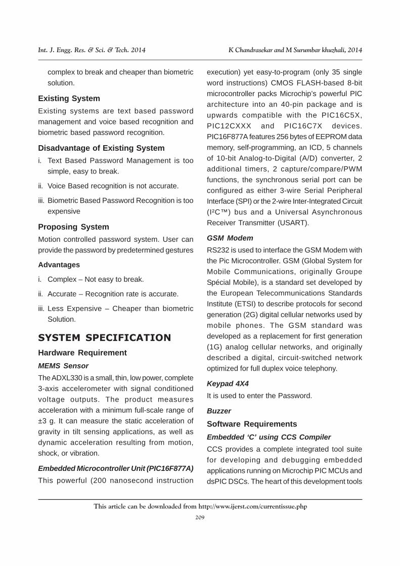
In this project, Motion Controlled Password Recognition system using MEMS accelerometer isimplemented using embedded microcontroller. MEMS accelerometer can sense motion in 3axes (X, Y and Z). Microcontroller analyzes whether any motion is occurring and in the absenceof a motion for a predetermined duration, forces the system to go into a low-power mode. Theuser can assign a predetermined password by fixed set of motions as decided by them. Oncethe Microcontroller senses any motion, it uses the GSM modem to send the random numberwhich is generated in it. User receives the sms and enters the random number in keypad.Controller analyzes the motion pattern of the user and provided authorized random number. Ifboth the parameters are matched, the lock will be unlocked.
Keywords: Accelerometer, Keypad, Password Recognition, GSM Modem
*Corresponding Author:K Chandrasekar � [email protected]
INTRODUCTION
The loss of materials and equipment’s due to theft
is currently a massive problem in most of the
firms. Theft can be significantly reduced through
proactive management techniques that
emphasize the implementation of rigorous project-
specific security programs. This paper presents
an advanced authentication based on motion of
the system. Unlike most of the previous
authentication like biometric, cards to swipe it’s
entirely different and more reliable. Using machine
motion techniques, in our approach logical
patterns are obtained from physical sensor
attached to the system.
1 Department of Electronics & Telecommunication Engineering, Bharath University, Chennai, Tamil Nadu, India.
Int. J. Engg. Res. & Sci. & Tech. 2014
ISSN 2319-5991 www.ijerst.com
Vol. 3, No. 2, May 2014
© 2014 IJERST. All Rights Reserved
Research Paper
SYSTEM ANALYSIS
1. Text Based Password Management is simple
and easy to break.
2. Voice Based recognition is not accurate.
3. Biometric Based Password Recognition is too
expensive. Above type of password system are
not more secured one so my password are
assigned to motion to system. User can
provide the password by predetermined and
using correct motion then only recognize that
correct motion passwords. Compare to other
security system, it has two security methods
these are text based and then motion based
security. Main advantage of this system is
209
This article can be downloaded from http://www.ijerst.com/currentissue.php
Int. J. Engg. Res. & Sci. & Tech. 2014 K Chandrasekar and M Surumbar khuzhali, 2014
complex to break and cheaper than biometric
solution.
Existing System
Existing systems are text based password
management and voice based recognition and
biometric based password recognition.
Disadvantage of Existing System
i. Text Based Password Management is too
simple, easy to break.
ii. Voice Based recognition is not accurate.
iii. Biometric Based Password Recognition is too
expensive
Proposing System
Motion controlled password system. User can
provide the password by predetermined gestures
Advantages
i. Complex – Not easy to break.
ii. Accurate – Recognition rate is accurate.
iii. Less Expensive – Cheaper than biometric
Solution.
SYSTEM SPECIFICATION
Hardware Requirement
MEMS Sensor
The ADXL330 is a small, thin, low power, complete
3-axis accelerometer with signal conditioned
voltage outputs. The product measures
acceleration with a minimum full-scale range of
±3 g. It can measure the static acceleration of
gravity in tilt sensing applications, as well as
dynamic acceleration resulting from motion,
shock, or vibration.
Embedded Microcontroller Unit (PIC16F877A)
This powerful (200 nanosecond instruction
execution) yet easy-to-program (only 35 single
word instructions) CMOS FLASH-based 8-bit
microcontroller packs Microchip’s powerful PIC
architecture into an 40-pin package and is
upwards compatible with the PIC16C5X,
PIC12CXXX and PIC16C7X devices.
PIC16F877A features 256 bytes of EEPROM data
memory, self-programming, an ICD, 5 channels
of 10-bit Analog-to-Digital (A/D) converter, 2
additional timers, 2 capture/compare/PWM
functions, the synchronous serial port can be
configured as either 3-wire Serial Peripheral
Interface (SPI) or the 2-wire Inter-Integrated Circuit
(I²C™) bus and a Universal Asynchronous
Receiver Transmitter (USART).
GSM Modem
RS232 is used to interface the GSM Modem with
the Pic Microcontroller. GSM (Global System for
Mobile Communications, originally Groupe
Spécial Mobile), is a standard set developed by
the European Telecommunications Standards
Institute (ETSI) to describe protocols for second
generation (2G) digital cellular networks used by
mobile phones. The GSM standard was
developed as a replacement for first generation
(1G) analog cellular networks, and originally
described a digital, circuit-switched network
optimized for full duplex voice telephony.
Keypad 4X4
It is used to enter the Password.
Buzzer
Software Requirements
Embedded ‘C’ using CCS Compiler
CCS provides a complete integrated tool suite
for developing and debugging embedded
applications running on Microchip PIC MCUs and
dsPIC DSCs. The heart of this development tools
210
This article can be downloaded from http://www.ijerst.com/currentissue.php
Int. J. Engg. Res. & Sci. & Tech. 2014 K Chandrasekar and M Surumbar khuzhali, 2014
suite is the CCS intelligent code optimizing
Microchip PIC C compiler which frees developers
to concentrate on design functionality instead of
having to become an MCU architecture expert.
PIC Downloader
Using PIC Downloader to implement the
Embedded ‘C coding system into Microcontroller
by PC Serial Communication port.
Simulation Software
Proteus is simulation software which is used to
simulate our project.
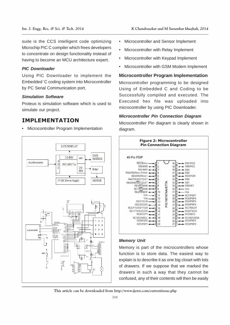
IMPLEMENTATION
• Microcontroller Program Implementation
• Microcontroller and Sensor Implement
• Microcontroller with Relay Implement
• Microcontroller with Keypad Implement
• Microcontroller with GSM Modem Implement
Microcontroller Program Implementation
Microcontroller programming to be designed
Using of Embedded C and Coding to be
Successfully compiled and executed. The
Executed hex file was uploaded into
microcontroller by using PIC Downloader.
Microcontroller Pin Connection Diagram
Microcontroller Pin diagram is clearly shown in
diagram.
Figure 2: MicrocontrollerPin Connection Diagram
Memory Unit
Memory is part of the microcontrollers whose
function is to store data. The easiest way to
explain is to describe it as one big closet with lots
of drawers. If we suppose that we marked the
drawers in such a way that they cannot be
confused, any of their contents will then be easily
211
This article can be downloaded from http://www.ijerst.com/currentissue.php
Int. J. Engg. Res. & Sci. & Tech. 2014 K Chandrasekar and M Surumbar khuzhali, 2014
accessible. It is enough to know the designation
of the drawer and so its contents will be known to
us for sure.
A. Memory Unit of Microcontroller
Memory components are exactly like that for a
certain input we get the contents of a certain
addressed memory location and that’s all. Two
new concepts are brought to addressing and
memory location. Memory consists of all memory
locations and addressing is nothing but selecting
one of them.
B. Central Processing Unit
Let add three memory locations to a specific block
that will have a built in capability to multiply, divide,
subtract and move its contents from one memory
location onto another. The part we just in are called
“Central Processing Unit” (CPU). Its memory
locations are called registers. Registers are
therefore memory locations whose role is to help
with performing various mathematical operations
or any other operations with data wherever data
can be found. Look at the current situation.
C. Input-Output Unit
Those locations we’ve just added are called
“ports”. There are several types of ports: Input,
output or bidirectional ports. When working with
ports, first of all it is necessary to choose which
port we need to work with, and then to send data
to, or take it from the port. When working with it
the port acts like a memory location. Something
is simply being written into or read from it and it
could be noticed on the pins of the microcontroller.
D. Serial Communication
Beside stated above we’ve added to the already
existing unit the possibility of communication with
an outside world. However, this way of
communicating has drawbacks. One of the basic
drawbacks is the number of lines which need to
be used in order to transfer data. The number of
lines time’s numbers of kilometers doesn’t
promise the economy of the project. It leaves us
having to reduce the number of lines in such a
way that we don’t lessen its functionality. Suppose
we are working with three lines only, and that one
line is used for sending data other for receiving,
and the third one is used as a reference line for
both the input and output side.
MEMS SENSOR
Micro electro mechanical systems or MEMS are
integrated micro devices or systems combining
electrical and mechanical components. They are
fabricated using Integrated Circuit (IC) batch
processing techniques and can range in size from
micrometers to millimeters. These systems can
sense control and actuate on the micro scale and
function individually or in arrays to generate
effects on the micro scale. “The field of MEMS is
based on the use of IC fabrication techniques to
create devices capable of acting as mechanical,
electrical, and chemical transducers for
applications in areas such as automotive and
medical industries.” It can be difficult for one to
imagine the size of MEMS device. The general
size of MEMS is on the order of microns (10
powers -6 m). The main characteristic of MEMS
is their small size. Due to their size, MEMS cannot
be seen with the unaided eye. An optical
microscope is usually required for one to be able
to see them.
Microcontroller with Relay Implement
It is used to Microcontroller output to be evaluated
through Relay. Relay is used to locked Magnetic
door to be released for Microcontroller activities
that is using sensor the motion to be captured for
correctly means the micro controller to be
212
This article can be downloaded from http://www.ijerst.com/currentissue.php
Int. J. Engg. Res. & Sci. & Tech. 2014 K Chandrasekar and M Surumbar khuzhali, 2014
instructed to relay the door to be released
otherwise the door locked state.
Microcontroller with Keypad Implement
It is used to enter the password which is send by
the microcontroller through the GSM Modem.
A keypad is a set of buttons arranged in a block
or “pad” which usually bear digits, symbols and
usually a complete set of alphabetical letters. If it
mostly contains numbers, then it can also be
called a numeric keypad. Here we are using 4 X
4 matrix keypad.
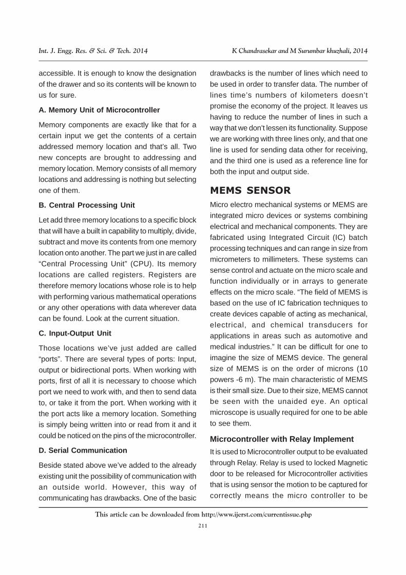
Interfacing Keypad
Figure 3 shows how to interface the 4 X 4 matrix
keypad to Port C in microcontroller. The rows are
connected to an output port and the columns are
connected to an input port. To detect a pressed
key, the microcontroller grounds all rows by
providing 0 to the output latch, and then it reads
the columns. If the data read from the columns is
C6-C4&D6=1111, no key has been pressed and
the process continues until a key press is
detected. However, if one of the column bits has
a zero, this means that a key press has occurred.
For example, if C3-C0=1101, this means that a
key in the D1 column has been pressed. After a
key press is detected, the microcontroller will go
through the process of identifying the key.
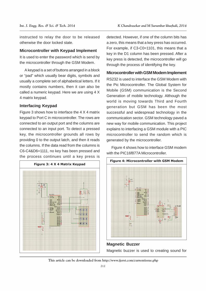
Microcontroller with GSM Modem Implement
RS232 is used to interface the GSM Modem with
the Pic Microcontroller. The Global System for
Mobile (GSM) communication is the Second
Generation of mobile technology. Although the
world is moving towards Third and Fourth
generation but GSM has been the most
successful and widespread technology in the
communication sector. GSM technology paved a
new way for mobile communication. This project
explains to interfacing a GSM module with a PIC
microcontroller to send the random which is
generated by the microcontroller.
Figure 4 shows how to interface GSM modem
with the PIC16f877A Microcontroller.
Magnetic Buzzer
Magnetic buzzer is used to creating sound for
Figure 3: 4 X 4 Matrix KeypadFigure 4: Microcontroller with GSM Modem

213
This article can be downloaded from http://www.ijerst.com/currentissue.php
Int. J. Engg. Res. & Sci. & Tech. 2014 K Chandrasekar and M Surumbar khuzhali, 2014
wrong motion passwords. A buzzer or beeper is
an audio signaling device, which may be
mechanical, electromechanical, or piezoelectric.
Typical uses of buzzers and beepers include
alarm devices, timers and confirmation of user
input such as a mouse click or keystroke.
Figure 5: Magnetic Buzzer
Features
i. Small size and Lightweight
ii. Wave soldering and washing
iii. High reliable and long life
iv. Low voltage and low drain
Applications
i. Electronic instrument, medical instrument
ii. Computer and peripheral units
iii. Various home appliances, office equipment
iv. Cash register, Credit card readers.
Simulation Results: Proteus Software
Figure 6: Simulation Results:Proteus Software
214
This article can be downloaded from http://www.ijerst.com/currentissue.php
Int. J. Engg. Res. & Sci. & Tech. 2014 K Chandrasekar and M Surumbar khuzhali, 2014
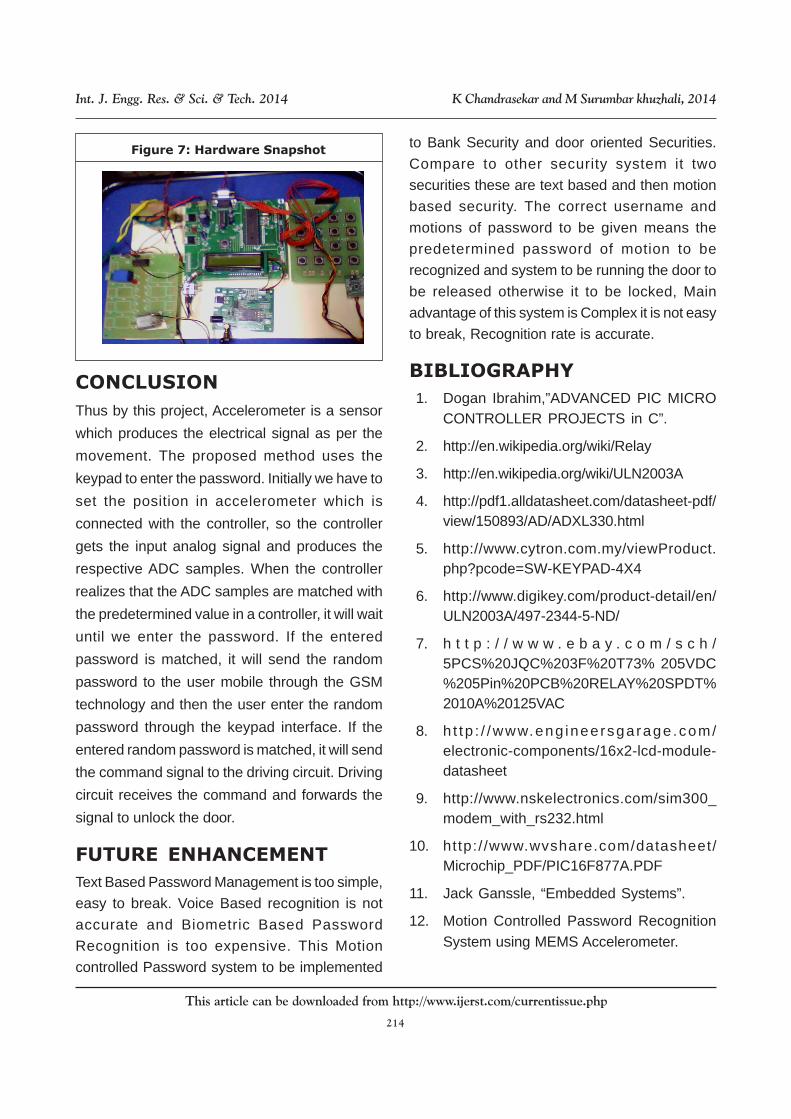
CONCLUSION
Thus by this project, Accelerometer is a sensor
which produces the electrical signal as per the
movement. The proposed method uses the
keypad to enter the password. Initially we have to
set the position in accelerometer which is
connected with the controller, so the controller
gets the input analog signal and produces the
respective ADC samples. When the controller
realizes that the ADC samples are matched with
the predetermined value in a controller, it will wait
until we enter the password. If the entered
password is matched, it will send the random
password to the user mobile through the GSM
technology and then the user enter the random
password through the keypad interface. If the
entered random password is matched, it will send
the command signal to the driving circuit. Driving
circuit receives the command and forwards the
signal to unlock the door.
FUTURE ENHANCEMENT
Text Based Password Management is too simple,
easy to break. Voice Based recognition is not
accurate and Biometric Based Password
Recognition is too expensive. This Motion
controlled Password system to be implemented
to Bank Security and door oriented Securities.
Compare to other security system it two
securities these are text based and then motion
based security. The correct username and
motions of password to be given means the
predetermined password of motion to be
recognized and system to be running the door to
be released otherwise it to be locked, Main
advantage of this system is Complex it is not easy
to break, Recognition rate is accurate.
BIBLIOGRAPHY
1. Dogan Ibrahim,”ADVANCED PIC MICROCONTROLLER PROJECTS in C”.
2. http://en.wikipedia.org/wiki/Relay
3. http://en.wikipedia.org/wiki/ULN2003A
4. http://pdf1.alldatasheet.com/datasheet-pdf/view/150893/AD/ADXL330.html
5. http://www.cytron.com.my/viewProduct.php?pcode=SW-KEYPAD-4X4
6. http://www.digikey.com/product-detail/en/ULN2003A/497-2344-5-ND/
7. h t t p : / / w w w . e b a y . c o m / s c h /5PCS%20JQC%203F%20T73% 205VDC%205Pin%20PCB%20RELAY%20SPDT%2010A%20125VAC
8. h t tp : / /www.eng ineersgarage .com/electronic-components/16x2-lcd-module-datasheet
9. http://www.nskelectronics.com/sim300_modem_with_rs232.html
10. http:/ /www.wvshare.com/datasheet/Microchip_PDF/PIC16F877A.PDF
11. Jack Ganssle, “Embedded Systems”.
12. Motion Controlled Password RecognitionSystem using MEMS Accelerometer.
Figure 7: Hardware Snapshot