RESEARCH Open Access Three-dimensional methodology for ...
15
RESEARCH Open Access Three-dimensional methodology for photogrammetric acquisition of the soft tissues of the face: a new clinical-instrumental protocol Roberto Deli 1 , Luigi M Galantucci 2 , Alberto Laino 3 , Raoul D’Alessio 1 , Eliana Di Gioia 4* , Carmela Savastano 5 , Fulvio Lavecchia 6 and Gianluca Percoco 2 Abstract Background: The objective of this study is to define an acquisition protocol that is clear, precise, repeatable, simple, fast and that is useful for analysis of the anthropometric characteristics of the soft tissue of the face. Methods: The analysis was carried out according to a new clinical-instrumental protocol that comprises four distinct phases: (1) setup of portable equipment in the space in which field analysis will be performed, (2) preparation of the subject and spatial positioning, (3) scanning of the subject with different facial expressions, and (4) treatment and processing of data. The protocol was tested on a sample comprising 66 female subjects (64 Caucasian, 1 Ethiopian, and 1 Brazilian) who were the finalists of an Italian national beauty contest in 2010. To illustrate the potential of the method, we report here the measurements and full analysis that were carried out on the facial model of one of the subjects who was scanned. Results: This new protocol for the acquisition of faces is shown to be fast (phase 1, about 1 h; phase 2, about 1.5 min; phase 3, about 1.5 min; phase 4, about 15 min), simple (phases 1 to 3 requiring a short operator training period; only phase 4 requires expert operators), repeatable (with direct palpation of anatomical landmarks and marking of their positions on the face, the problem of identification of these same landmarks on the digital model is solved), reliable and precise (average precision of measurements, 0.5 to 0.6 mm over the entire surface of the face). Conclusions: This standardization allows the mapping of the subjects to be carried out following the same conditions in a reliable and fast process for all of the subjects scanned. Keywords: Photogrammetric face scanner; Anthropometry; Facial soft tissue; 3D measurements; Aesthetic analysis Background The need for three-dimensional (3D), noninvasive methods and diagnostic tools that can be used in addition to, or as an alternative to, radiographic methods has stimulated a growing interest in facial anthropometry. This is based on the mapping and measurement of the soft tissue of the face [1,2]. To make better use of the potential of these methods, it is necessary to have reliable anthropometric data of reference populations, which is made possible through the analysis of a suitably large number of represen- tative samples. It is therefore essential to have a highly stan- dardized clinical-instrumental protocol that allows precise, repeatable, fast, and simple data acquisition that can be used for subjects of different ages and abilities to cooperate. This can then be used for the survey of suitably large sam- ples that are representative of different subjects, and it should also be easy enough to carry out repeated mapping over time (i.e., monitoring of the spontaneous evolution of clinical cases or results obtained under given treatments). There are various methods for the acquisition of data relating to the shape of a 3D object [3-6]. Digital close- range photogrammetry is suitable for use in medicine. The 3D information is obtained through the acquisition and comparison of a number of specific photographic images [7-9] that make use of the principle of triangula- tion, as shown schematically in Figure 1. For each couple of camera stations (CS2, CS3) rigidly positioned in the * Correspondence: [email protected] 4 Studio Associato di Odontoiatria dei Dottori Di Gioia, Bari 70122, Italy Full list of author information is available at the end of the article © 2013 Deli et al.; licensee Springer. This is an Open Access article distributed under the terms of the Creative Commons Attribution License (http://creativecommons.org/licenses/by/2.0), which permits unrestricted use, distribution, and reproduction in any medium, provided the original work is properly cited. Deli et al. Progress in Orthodontics 2013, 14:32 http://www.progressinorthodontics.com/content/14/1/32
Transcript of RESEARCH Open Access Three-dimensional methodology for ...

Deli et al. Progress in Orthodontics 2013, 14:32http://www.progressinorthodontics.com/content/14/1/32
RESEARCH Open Access
Three-dimensional methodology forphotogrammetric acquisition of the soft tissuesof the face: a new clinical-instrumental protocolRoberto Deli1, Luigi M Galantucci2, Alberto Laino3, Raoul D’Alessio1, Eliana Di Gioia4*, Carmela Savastano5,Fulvio Lavecchia6 and Gianluca Percoco2
Abstract
Background: The objective of this study is to define an acquisition protocol that is clear, precise, repeatable,simple, fast and that is useful for analysis of the anthropometric characteristics of the soft tissue of the face.
Methods: The analysis was carried out according to a new clinical-instrumental protocol that comprises four distinctphases: (1) setup of portable equipment in the space in which field analysis will be performed, (2) preparation of thesubject and spatial positioning, (3) scanning of the subject with different facial expressions, and (4) treatment andprocessing of data. The protocol was tested on a sample comprising 66 female subjects (64 Caucasian, 1 Ethiopian,and 1 Brazilian) who were the finalists of an Italian national beauty contest in 2010. To illustrate the potential of themethod, we report here the measurements and full analysis that were carried out on the facial model of one of thesubjects who was scanned.
Results: This new protocol for the acquisition of faces is shown to be fast (phase 1, about 1 h; phase 2, about 1.5 min;phase 3, about 1.5 min; phase 4, about 15 min), simple (phases 1 to 3 requiring a short operator training period; onlyphase 4 requires expert operators), repeatable (with direct palpation of anatomical landmarks and marking of theirpositions on the face, the problem of identification of these same landmarks on the digital model is solved), reliable andprecise (average precision of measurements, 0.5 to 0.6 mm over the entire surface of the face).
Conclusions: This standardization allows the mapping of the subjects to be carried out following the same conditionsin a reliable and fast process for all of the subjects scanned.
Keywords: Photogrammetric face scanner; Anthropometry; Facial soft tissue; 3D measurements; Aesthetic analysis
BackgroundThe need for three-dimensional (3D), noninvasive methodsand diagnostic tools that can be used in addition to, or asan alternative to, radiographic methods has stimulated agrowing interest in facial anthropometry. This is basedon the mapping and measurement of the soft tissue of theface [1,2]. To make better use of the potential of thesemethods, it is necessary to have reliable anthropometricdata of reference populations, which is made possiblethrough the analysis of a suitably large number of represen-tative samples. It is therefore essential to have a highly stan-dardized clinical-instrumental protocol that allows precise,
* Correspondence: [email protected] Associato di Odontoiatria dei Dottori Di Gioia, Bari 70122, ItalyFull list of author information is available at the end of the article
© 2013 Deli et al.; licensee Springer. This is anAttribution License (http://creativecommons.orin any medium, provided the original work is p
repeatable, fast, and simple data acquisition that can beused for subjects of different ages and abilities to cooperate.This can then be used for the survey of suitably large sam-ples that are representative of different subjects, and itshould also be easy enough to carry out repeated mappingover time (i.e., monitoring of the spontaneous evolution ofclinical cases or results obtained under given treatments).There are various methods for the acquisition of data
relating to the shape of a 3D object [3-6]. Digital close-range photogrammetry is suitable for use in medicine.The 3D information is obtained through the acquisitionand comparison of a number of specific photographicimages [7-9] that make use of the principle of triangula-tion, as shown schematically in Figure 1. For each coupleof camera stations (CS2, CS3) rigidly positioned in the
Open Access article distributed under the terms of the Creative Commonsg/licenses/by/2.0), which permits unrestricted use, distribution, and reproductionroperly cited.

Figure 1 The principle of triangulation as used for digital close-range photogrammetry. CS2 and CS3, camera stations; h, α, β, distanceand angles between the cameras; b, calculated z distance of the single point from the cameras.
Deli et al. Progress in Orthodontics 2013, 14:32 Page 2 of 15http://www.progressinorthodontics.com/content/14/1/32
space, for each corresponding point P(x, y) in the twoimages, it is possible to calculate the third coordinate zas the value of b in the triangle, knowing the distanceand angles between the cameras (h, α, β).The photographs must be taken from at least two dif-
ferent positions, such that through the intersection ofthe virtual lines drawn from each of the cameras to theobject (here, the face), it is possible to define the 3D co-ordinates of the points of interest and, therefore, theshape and size of the object [10]. The positions and anglesof orientation of each of the cameras must be known forall of the pictures in a dataset [11].A 3D model of the facial soft tissue can then be
obtained in the form of a point cloud, which provides alist of points described according to their spatial coordi-nates. Through the connection and recognition of thecharacteristics that bind these 3D points in the cloud, amesh is created, i.e., a reconstruction of the face thatconsists of tiny polygons, usually triangles. A computerequipped with the photogrammetric software can thenbe used to process the images (Figure 2).A new method of 3D scanning can be used to create
dense 3D point clouds and to reconstruct a detailed vir-tual model of the surfaces, which is known as photo-based scanning. This process uses digital cameras incombination with algorithms that analyze digital images[11]. The algorithm for the processing of the scanscompares image pairs on the basis of small portions(or patches), area by area, evaluating which patches cor-respond to one another. Once the optimal correspondenceis defined, the position and orientation already computedfor photographs are used to calculate the position of thispatch in the 3D space. The accuracy and reliability of 3Dmeasurements of facial soft tissue were evaluated by
Swennen et al. [12] through comparisons of data obtainedon the same sample of subjects using 3D computer tomog-raphy and 3D stereophotogrammetry. The measurementof the facial soft tissue with 3D computer tomographyshowed great accuracy, except for the landmarks ofthe hairline, the eyebrows, and the eyelids. In contrast,3D stereophotogrammetry showed great accuracy andreliability, except for the bony landmarks. Thus, thecombination of 3D computer tomography and 3Dstereophotogrammetry for the analysis of facial softtissue allows these problems related to the hairline,eyebrows, eyelids, and the bony landmarks to be overcome[12]. The study of Ghoddousi et al. [13] compared theaccuracy of the mapping of facial soft tissue using 3Dstereophotogrammetry, manual anthropometric measure-ments, and 2D photographs. These three methods showedgood repeatability of measurements. The level of accuracyof the 3D stereophotogrammetric system was very satisfac-tory, both for the measurement of distances and for themapping of surfaces. Indeed, the measurements obtainedwith the 3D systems were sufficiently accurate and reliableenough for clinical use [14].In surface anthropometry, indirect methods (i.e., those
without direct physical contact between the subject andthe mapping system), such as photogrammetry, haveseveral advantages over direct methods (i.e., those withdirect physical contact needed). This can be seen whenthe sensors of the equipment used for direct methodscan deform the facial surface during measurements, al-beit only slightly, and thus contribute as a source ofinaccuracy. Instead, photogrammetric methods are rela-tively insensitive to slight movements of the body, as thetime of interaction with the subject is shorter, and there-fore, this method is less influenced by any behavior of the

Figure 2 The images captured with the use of five cameras.
Deli et al. Progress in Orthodontics 2013, 14:32 Page 3 of 15http://www.progressinorthodontics.com/content/14/1/32
subject. Moreover, some measurements, such as thoserelating to the eyes, are difficult to obtain with directmapping methods, without causing discomfort or possibleinjury to the patient [12,14,15].Previous studies investigated on the accuracy of the
measurements made using photogrammetric face scan-ners. Rangel et al. [16] presented a study using 3dMD™(Atlanta, GA, USA) stereophotogrammetric system: theyobtained a 3D digital model having an average errorof 0.35 mm with a standard deviation of 0.32 mm.Khambay et al. [17] validated a high-resolution 3D im-aging system (Di3D™, Dimensional Imaging Ltd., Glasgow,Scotland, UK) using only ten landmarks on facial plastercasts, comparing the results with those obtained by acoordinate-measuring machine (CMM), reporting a systemerror of 0.2 mm and a reproducibility error of less than0.5 mm. Winder et al. [18] used 18 landmarks on a manne-quin head to validate a Di3D™ system, using comparisonlaser scans and digital caliper measures, having mean dif-ferences between measures of 0.62 mm. In 2010, Lübberset al. [19] examined the precision and accuracy of the3dMD™ system using 41 landmarks on a mannequin head:they report a mean global error of 0.2 mm (range 0.1 to0.5mm). More recently, they [20] repeated the experimentsusing 61 landmarks on two real faces, reporting a meanglobal error of 0.41 mm (range 0 to 3.3 mm). Deli et al.
[21,22] compared the results achieved with various photo-grammetric systems having different numbers and types ofcameras. Galantucci et al. [23] recently also developeda simple photogrammetric system for automatic captureand measurement of facial soft tissues during movement:digital close-range photogrammetry was used to acquirethe spatial coordinates of facial landmark points and tracktheir movements.In [24], the Face Shape Maxi5 3D photogrammetric
scanner developed by Polishape 3D srl (Bari, Italy), theone used in this study, was validated in terms of repro-ducibility and accuracy. Measurements were taken overa set of 23 anthropological soft tissue facial landmarksmarked on two different dummies, assessing photogram-metric software precision and system measurement ac-curacy. The operator error was measured by repeatedlydigitizing landmarks on the 3D model, and it was around0.059 mm. The reproducibility error was calculated bydigitizing landmarks on two different occasions. The aver-age Euclidean distance between the two matched sets ofcoordinates was thus computed, giving a result of approxi-mately 0.090 mm. Each dummy was digitized for compari-son using a CMM of documented accuracy (0.5 μm). Theas-obtained landmark coordinates were considered as the‘gold standard’. The system error mean value was thenfound to be equal to 0.425 mm, with a standard deviation

Deli et al. Progress in Orthodontics 2013, 14:32 Page 4 of 15http://www.progressinorthodontics.com/content/14/1/32
of 0.142 mm. Therefore, accuracy results suggested thatthe 3D scanning system used in this work was reliableenough to capture the facial morphology for clinical andanthropological usage.This methodology thus provides higher accuracy with
respect to laser scanning (Vivid 910i, Minolta, Osaka,Japan; a method based on triangulation and widely usedin the literature for 3D facial scans), which has an accur-acy of ±0.38 and ±0.31 mm in the X and Y directions,respectively, and ±0.2 mm in the Z direction.The aim of the study was to define a standardized
clinical-instrumental procedure to perform such facialscanning and mapping with the use of a specific 3Dphotogrammetric methodology that allows the recon-struction of 3D digital models of the face. Thus, with theaid of dedicated computer software, this allows quantita-tive and qualitative anthropometric evaluations of thesurface characteristics of the facial soft tissue.
MethodsThe 3D photogrammetric method that was designed andimplemented in the Laboratory of Rapid Prototypingand Reverse Engineering in Politecnico di Bari (Italy)using the equipment shown in Figure 3. The choice ofphotogrammetry over other optical scanning methods,such as laser or structured light, was done because photo-grammetry is the only method that allows simultan-eous acquisition of a large visual and angular field in amuch shorter time (1/100 to 1/5,000 s) than with othertechniques [3].The equipment used included five high-definition digital
single-lens reflex cameras with flash (Canon 40D, 10 Mpx)that were suitably mounted on a specific rigid struc-ture and connected via computer for their simultaneous
Figure 3 Face Shape Maxi 5 of Polishape 3D (a spin-off company of P
operation. The processing of the point clouds and thecreation of the virtual 3D models were carried out throughthe use of photogrammetric reconstruction algorithms[25,26]. The operational protocol designed for this facialscanning consisted of four phases defined as follows [27]:
� Phase 1: initial setup and preparation of the scanningdevice. The cameras are mounted on an aluminumframe structure on a robust tripod. The structurecontains synchronization and data communicationelectronics, electric tension transformers, and all ofthe connecting cables. This frame is designed andbuilt to allow the correct orientation with respect tothe face to be scanned (Figure 3). The structure ispositioned at a distance of about 1 m from the subjectand connected to a laptop computer used for theremote control of the cameras and to record theimages acquired. Two multi-phosphorus fluorescentdaylight lamps are positioned for the diffuse illu-mination of the subject and to facilitate the focusingoperations. The background is provided with codedtargets, in front of which the subject is seated on astool that is height adjustable.
� Phase 2: preparation of the face to be mapped. The facemust be free of make-up, with the hair back, to clearlyand completely expose the parts of the face to bemapped and the natural texture of the skin. Anoperator identifies the anatomical skin landmarks onthe face through direct method of inspection andpalpation. In the present study, 33 landmarks wereused, as selected from those according to Sforza et al.and Swennen and Farkas [28-32], and as illustratedin Figure 4. These were then marked by the sameoperator using hypoallergenic eyeliner to more easily
olitecnico di Bari).
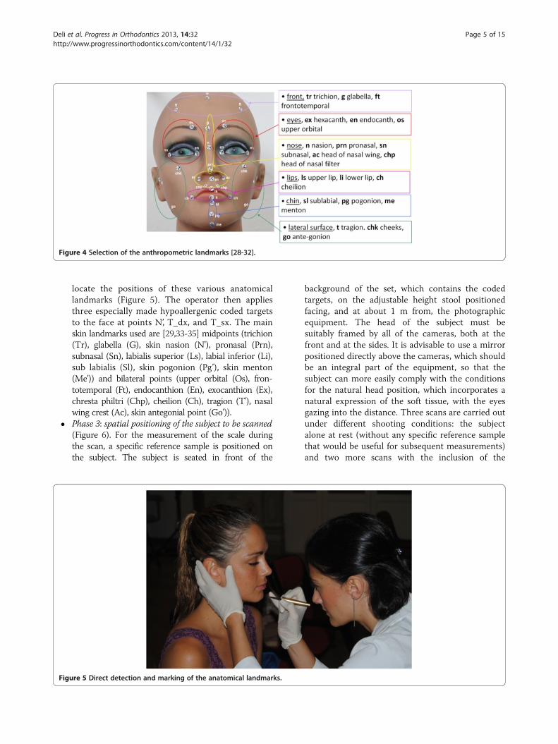
Figure 4 Selection of the anthropometric landmarks [28-32].
Deli et al. Progress in Orthodontics 2013, 14:32 Page 5 of 15http://www.progressinorthodontics.com/content/14/1/32
locate the positions of these various anatomicallandmarks (Figure 5). The operator then appliesthree especially made hypoallergenic coded targetsto the face at points N’, T_dx, and T_sx. The mainskin landmarks used are [29,33-35] midpoints (trichion(Tr), glabella (G), skin nasion (N’), pronasal (Prn),subnasal (Sn), labialis superior (Ls), labial inferior (Li),sub labialis (Sl), skin pogonion (Pg’), skin menton(Me’)) and bilateral points (upper orbital (Os), fron-totemporal (Ft), endocanthion (En), exocanthion (Ex),chresta philtri (Chp), cheilion (Ch), tragion (T’), nasalwing crest (Ac), skin antegonial point (Go’)).
� Phase 3: spatial positioning of the subject to be scanned(Figure 6). For the measurement of the scale duringthe scan, a specific reference sample is positioned onthe subject. The subject is seated in front of the
Figure 5 Direct detection and marking of the anatomical landmarks.
background of the set, which contains the codedtargets, on the adjustable height stool positionedfacing, and at about 1 m from, the photographicequipment. The head of the subject must besuitably framed by all of the cameras, both at thefront and at the sides. It is advisable to use a mirrorpositioned directly above the cameras, which shouldbe an integral part of the equipment, so that thesubject can more easily comply with the conditionsfor the natural head position, which incorporates anatural expression of the soft tissue, with the eyesgazing into the distance. Three scans are carried outunder different shooting conditions: the subjectalone at rest (without any specific reference samplethat would be useful for subsequent measurements)and two more scans with the inclusion of the

Figure 6 Spatial positioning of the subject to be scanned.
Deli et al. Progress in Orthodontics 2013, 14:32 Page 6 of 15http://www.progressinorthodontics.com/content/14/1/32
reference sample that is applied directly on thesubject: the first of these under conditions of rest,and the second, while smiling. The necessaryinstructions are provided to ensure that during thescanning, while resting, the subject retains theirusual dental occlusion (so as not to alter theiranthropometric measurements), with the lips at restand maintaining a very natural facial expression;even the acquisition while the subject is smiling hasto maintain the same conditions.
� Phase 4: data processing. Using the appropriate pro-cedures, a very dense 3D cloud of the spatial pointsis obtained (potentially with millions of points). The 3Dindividual digital models are created from this 3D
cloud (Figure 7). Finally, an automatic procedure forthe extraction of the 3D models and the storage of thecoordinates of the selected landmarks is also created.
This new clinical-instrumental protocol for photogram-metric acquisition was applied for the first time to acquirethe faces of a sample of 66 female subjects (64 Caucasian,1 Ethiopian, and 1 Brazilian), who are finalists in an Italiannational beauty contest in 2010. Each subject explicitlyexpressed their free and voluntary participation in thisstudy and allowed the 3D photogrammetric scanning oftheir face and related facial analyses. The 3D scanning oftheir faces was all carried out on the same day, having atleast three different scans for each subject.

Figure 7 Three-dimensional model of subject Miss TF.
Deli et al. Progress in Orthodontics 2013, 14:32 Page 7 of 15http://www.progressinorthodontics.com/content/14/1/32
The software used for photogrammetric processingwas PhotoModeler™ Scanner version 6 (Eos Systems Inc.,Vancouver, BC, Canada), while for the development of the3D models, Geomagic™ version10 (Morrisville, NC, USA)was used. PhotoModeler provides estimates of how precisethe positions of the points computed are, using the pro-cessing algorithm.On the basis of these coordinates, it is possible to identify
a series of anthropometric measurements and angles thatcan provide a guide and tool for surgeons and orthodon-tists involved in the reevaluation of female faces. The ithlinear distance was calculated as
distanceik ¼ffiffiffiffiffiffiffiffiffiffiffiffiffiffiffiffiffiffiffiffiffiffiffiffiffiffiffiffiffiffiffiffiffiffiffiffiffiffiffiffiffiffiffiffiffiffiffiffiffiffiffiffiffiffiffiffiffiffiffiffiffixj−xkð Þ2 þ yj−ykð Þ2 þ zj−zkð Þ2
qð1Þ
where x, y, and z are the spatial coordinates of the j and klandmarks.The (rp-rq)ith angle measurement was calculated (in
sexagesimal degrees) using Equation 2:
Angle rp−rqð Þi ¼Degree Arccos1þmp �mqþ np � nqð Þffiffiffiffiffiffiffiffiffiffiffiffiffiffiffiffiffiffiffiffiffiffiffiffiffiffiffiffiffiffiffiffiffiffiffiffiffiffiffiffiffiffiffiffiffiffiffiffiffiffiffiffiffiffiffiffiffiffiffiffiffiffiffiffiffiffiffiffiffiffiffiffiffiffi
1þmp2 þ nq2ð Þ � 1þmp2 þ nq2ð Þ½ �p ! !
ð2Þ
where
� mp and np are the slopes of the rp line, and mq andnq are the slopes of the rq line.
� rp and rq are the lines that form the angle underquery.

Deli et al. Progress in Orthodontics 2013, 14:32 Page 8 of 15http://www.progressinorthodontics.com/content/14/1/32
�m ¼ yk−yj
xk−xj
�n ¼ zk−zj
xk−xj
where x, y, and z are the coordinates of two points onthe r line.
Results and discussionResultsThis new protocol is very fast for the acquisition of theface. There is the need for about 1 h for the first phaseof the protocol (the preparation of the scanning systemand of the set must be performed only once for the in-stallation of the equipment, and then it can work for theacquisition of the whole sample to be scanned in thatenvironment). The subject preparation (second phase)takes about 1.5 min per subject; the correct subject posi-tioning and the acquisition of three scans (third phase)also takes for about 1.5 min per subject. The time takenby the system for each acquisition is actually 6 ms, asthe duration of the flash. The fourth phase of data pro-cessing requires about 15 min by a skilled operator(often an engineer) for the manipulation of the 3D im-ages. From previous studies using this methodology[21,24-26], the average accuracy of the measurementsmade onto the digital model, referring to the entire sur-face of the face, was 0.5 to 0.6 mm, while for the individualpoints (the coded targets), the measurement accuracyobtained was 0.03 mm in the X and Y directions and up to0.15 mm in the Z direction.
Figure 8 Anthropometric landmarks of subject Miss TF.
These three scans were then used to build the 3Ddigital models under the different shooting condi-tions of the scanning subject (subject under restingconditions without and with references samples andwhile smiling).These 3D digital models allow the automatic ex-
traction of the precise spatial coordinates of the ana-tomical landmarks selected (Figure 7). As indicatedabove, the direct pre-marking of the selected land-marks on the face makes these easily identifiable anduniquely recognizable on the virtual model of theface, allowing extremely precise anthropometric mea-surements [22,24,26].The standardization of the methodology made it pos-
sible to define the samples evenly, recreating the sameconditions of data acquisition for all the subjects. Fol-lowing these requirements for each of the four phases ofthe protocol provided good repeatability for data acquisi-tion [3,24,36], which was associated with excellent map-ping precision, which is an intrinsic characteristic of thismethodology [24,37].Figure 7 shows the development of the 3D model of
one of the subjects of the sample analyzed (Miss TF)and specifically the subject who should be the most at-tractive of all as she won the final of the 2010 competi-tion. Figure 8 shows the 3D spatial mapping of theanthropometric landmarks obtained via computer on thedigital images of subject Miss TF.The 3D coordinates of the anatomical landmarks and
the estimation of the accuracy of each measurement forsubject Miss TF are listed in Table 1.The linear and an-gular measurements and the measurement ratios of sub-ject Miss TF are given in Tables 2 and 3.
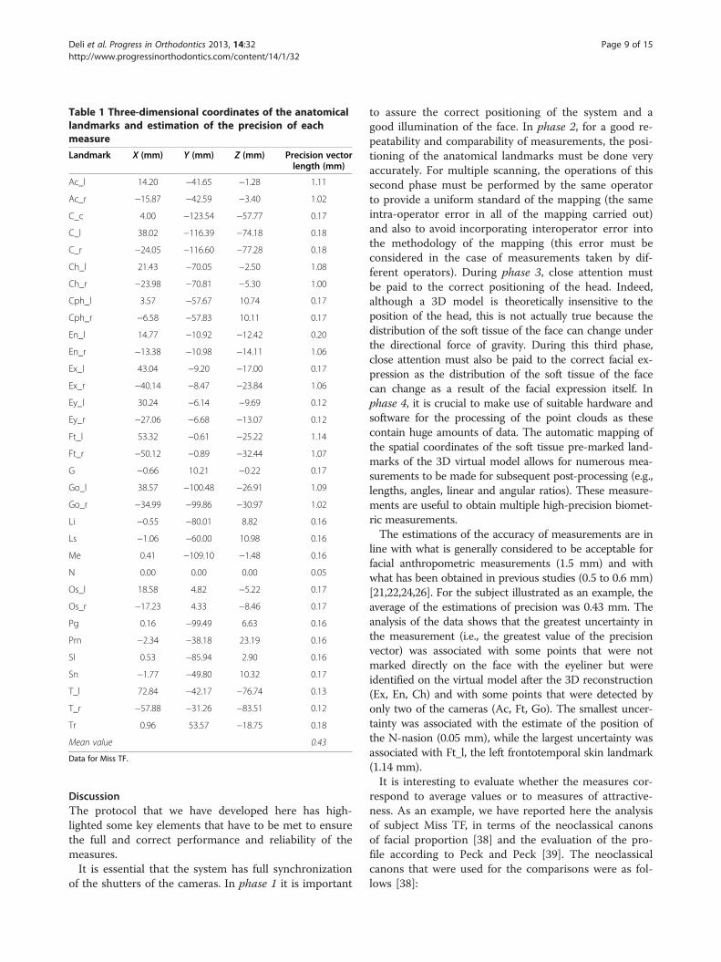
Table 1 Three-dimensional coordinates of the anatomicallandmarks and estimation of the precision of eachmeasure
Landmark X (mm) Y (mm) Z (mm) Precision vectorlength (mm)
Ac_l 14.20 −41.65 −1.28 1.11
Ac_r −15.87 −42.59 −3.40 1.02
C_c 4.00 −123.54 −57.77 0.17
C_l 38.02 −116.39 −74.18 0.18
C_r −24.05 −116.60 −77.28 0.18
Ch_l 21.43 −70.05 −2.50 1.08
Ch_r −23.98 −70.81 −5.30 1.00
Cph_l 3.57 −57.67 10.74 0.17
Cph_r −6.58 −57.83 10.11 0.17
En_l 14.77 −10.92 −12.42 0.20
En_r −13.38 −10.98 −14.11 1.06
Ex_l 43.04 −9.20 −17.00 0.17
Ex_r −40.14 −8.47 −23.84 1.06
Ey_l 30.24 −6.14 −9.69 0.12
Ey_r −27.06 −6.68 −13.07 0.12
Ft_l 53.32 −0.61 −25.22 1.14
Ft_r −50.12 −0.89 −32.44 1.07
G −0.66 10.21 −0.22 0.17
Go_l 38.57 −100.48 −26.91 1.09
Go_r −34.99 −99.86 −30.97 1.02
Li −0.55 −80.01 8.82 0.16
Ls −1.06 −60.00 10.98 0.16
Me 0.41 −109.10 −1.48 0.16
N 0.00 0.00 0.00 0.05
Os_l 18.58 4.82 −5.22 0.17
Os_r −17.23 4.33 −8.46 0.17
Pg 0.16 −99.49 6.63 0.16
Prn −2.34 −38.18 23.19 0.16
Sl 0.53 −85.94 2.90 0.16
Sn −1.77 −49.80 10.32 0.17
T_l 72.84 −42.17 −76.74 0.13
T_r −57.88 −31.26 −83.51 0.12
Tr 0.96 53.57 −18.75 0.18
Mean value 0.43
Data for Miss TF.
Deli et al. Progress in Orthodontics 2013, 14:32 Page 9 of 15http://www.progressinorthodontics.com/content/14/1/32
DiscussionThe protocol that we have developed here has high-lighted some key elements that have to be met to ensurethe full and correct performance and reliability of themeasures.It is essential that the system has full synchronization
of the shutters of the cameras. In phase 1 it is important
to assure the correct positioning of the system and agood illumination of the face. In phase 2, for a good re-peatability and comparability of measurements, the posi-tioning of the anatomical landmarks must be done veryaccurately. For multiple scanning, the operations of thissecond phase must be performed by the same operatorto provide a uniform standard of the mapping (the sameintra-operator error in all of the mapping carried out)and also to avoid incorporating interoperator error intothe methodology of the mapping (this error must beconsidered in the case of measurements taken by dif-ferent operators). During phase 3, close attention mustbe paid to the correct positioning of the head. Indeed,although a 3D model is theoretically insensitive to theposition of the head, this is not actually true because thedistribution of the soft tissue of the face can change underthe directional force of gravity. During this third phase,close attention must also be paid to the correct facial ex-pression as the distribution of the soft tissue of the facecan change as a result of the facial expression itself. Inphase 4, it is crucial to make use of suitable hardware andsoftware for the processing of the point clouds as thesecontain huge amounts of data. The automatic mapping ofthe spatial coordinates of the soft tissue pre-marked land-marks of the 3D virtual model allows for numerous mea-surements to be made for subsequent post-processing (e.g.,lengths, angles, linear and angular ratios). These measure-ments are useful to obtain multiple high-precision biomet-ric measurements.The estimations of the accuracy of measurements are in
line with what is generally considered to be acceptable forfacial anthropometric measurements (1.5 mm) and withwhat has been obtained in previous studies (0.5 to 0.6 mm)[21,22,24,26]. For the subject illustrated as an example, theaverage of the estimations of precision was 0.43 mm. Theanalysis of the data shows that the greatest uncertainty inthe measurement (i.e., the greatest value of the precisionvector) was associated with some points that were notmarked directly on the face with the eyeliner but wereidentified on the virtual model after the 3D reconstruction(Ex, En, Ch) and with some points that were detected byonly two of the cameras (Ac, Ft, Go). The smallest uncer-tainty was associated with the estimate of the position ofthe N-nasion (0.05 mm), while the largest uncertainty wasassociated with Ft_l, the left frontotemporal skin landmark(1.14 mm).It is interesting to evaluate whether the measures cor-
respond to average values or to measures of attractive-ness. As an example, we have reported here the analysisof subject Miss TF, in terms of the neoclassical canonsof facial proportion [38] and the evaluation of the pro-file according to Peck and Peck [39]. The neoclassicalcanons that were used for the comparisons were as fol-lows [38]:

Table 2 Linear and angular measurements and the measurement ratios of subject Miss TF
Landmarks involved Name Type and units Value
N-Pg Facial line Distance (mm) 99.7
N-P Nasion-midpoint of facial line Distance (mm) 49.9
P-Pg Midpoint of facial line-nasion Distance (mm) 49.9
P-M(T_r-T_l) Midpoint of facial line-midpoint of tragi Distance (mm) 84.8
N-Ls Nasion-Ls upper lip Distance (mm) 61.0
Ls-Prn Ls upper lip-pronasal Distance (mm) 25.0
N-M(T_r-T_l) Nasion-midpoint of tragi Distance (mm) 88.5
Prn-M(T_r-T_l) Pronasal-midpoint of tragi Distance (mm) 103.8
Ls-M(T_r-T_l) Upper lip-midpoint of tragi Distance (mm) 94.4
Pg-M(T_r-T_l) Pogonion-midpoint of tragi Distance (mm) 107.3
Tr-Sn Trichion-subnasal Distance (mm) 107.4
Tr-N 1° Third facial height Distance (mm) 56.8
N-Sn Anterior upper facial 2° third height Distance (mm) 50.9
Sn-Me Anterior upper facial 3° third height Distance (mm) 60.5
Ex_r-En_r Eye r Distance (mm) 28.6
Ex_l-En_l Eye l Distance (mm) 28.7
En_r-En_l Eye distance Distance (mm) 28.2
Ey_r-Ey_l Eye pupillar distance Distance (mm) 57.4
Ch_r-Ch_l Oral length Distance (mm) 45.5
Ac_r-Ac_l Nasal width Distance (mm) 30.2
1.5*(Ac_r-Ac_l) 1.5 × Nasal width Distance (mm) 45.2
Ex_r-N Exocantion r-nasion Distance (mm) 47.4
N-Ex_l Nasion-exocantion l Distance (mm) 47.2
Ex_r-Ex_l Upper facial width Distance (mm) 83.5
Go_l-Go_r Lower facial width Distance (mm) 73.7
Pg-M(Go_l-Go_r) Mandibular corpus length Distance (mm) 35.6
N-Prn Nasion-pronasal Distance (mm) 44.7
Prn-Pg Pronasal-pogonion Distance (mm) 63.6
N-Sn Anterior upper facial Distance (mm) 50.9
Sn-Pg Anterior lower facial height Distance (mm) 49.9
T_r-T_l Middle facial width Distance (mm) 131.4
Sn-(T_r-T_l) Middle facial depth Distance (mm) 91.9
Ch_l-Ch_r Mouth width Distance (mm) 45.5
Ls-(Prn-Pg) Upper lip to E-line distance Distance (mm) 6.1
Li-(Prn-Pg) Lower lip to E-line distance Distance (mm) 3.0
Sl-N Sublabial-nasion Distance (mm) 86.0
Prn-Sn Pronasal-subnasal Distance (mm) 17.3
Sn-Ls Subnasal-upper lip Distance (mm) 10.2
Ls-Pg Upper lip-pogonion Distance (mm) 39.7
T_r-Prn Tragion r-pronasal Distance (mm) 120.5
T_l-Prn Tragion l-pronasal Distance (mm) 125.1
T_r-Pg Tragion r-pogonion Distance (mm) 127.1
T_l-Pg Tragion l-pogonion Distance (mm) 124.6
T_r-N Tragion r-nasion Distance (mm) 106.3
Deli et al. Progress in Orthodontics 2013, 14:32 Page 10 of 15http://www.progressinorthodontics.com/content/14/1/32

Table 2 Linear and angular measurements and the measurement ratios of subject Miss TF (Continued)
T_l-N Tragion l-nasion Distance (mm) 113.9
Go_l-Pg Gonion l-pogonion Distance (mm) 51.0
Pg-Go_r Pogonion-gonion r Distance (mm) 51.5
T_r-Go_r Tragion r-gonion r Distance (mm) 89.4
T_l-Go_l Tragion l-gonion l Distance (mm) 84.0
T_l-Sn Trago_left-subnasal Distance (mm) 114.9
Sn-T_r Subnasale-trago_right Distance (mm) 107.4
Ls-Li Vermillion height Distance (mm) 20.1
Sl-Pg Sublabial-pogonion Distance (mm) 14.1
Ta
La
N-
Sl
Pr
(S
N-
T_
T_
T_
Sn
T_
T_
Go
T_
Ex
F
M
Nm
Na
M
M
Tv
(T
(N
(S
(T
(S
Deli et al. Progress in Orthodontics 2013, 14:32 Page 11 of 15http://www.progressinorthodontics.com/content/14/1/32
� Vertical proportions. The three facial sections of Tr-N,N-Sn, and Sn-Me must have the same length.
� Naso-aural proportions. The distances N-Sn and Sa-Sba must be the same.
� Naso-aural slope. The slope of the nose should beequal to the slope of the ear.
ble 3 Angular measurements and the measurement ratios of
ndmarks involved Name
Sn-Pg Facial convexity excluding the no
-N-Sn Maxillary prominence
n-Sn-Ls Naso-labial
n-Ls)^(Sl-Pg) Interlabial
Prn-Pg Nasion-pronasal-pogonion
l-Prn-T_r Tragion l-pronasal-tragion r
l-Pg-T_r Tragion l-pogonion-tragion r
l-N-T_r Tragion l-nasion-tragion r
-N-Prn Subnasale-nasion-pronasal
l-Go_l-Pg Tragion l-gonion l-pogonion
r-Go_r-Pg Tragion r-gonion r-pogonion
_l-Pg-Go_r Lower face convexity
l-Sn-T_r Middle face convexity
_r-N-Ex_l Upper facial convexity
(Pg-P-M(T_r-T_l)) Facial angle
f (Pg-N-Ls) Maxillo-facial angle
(Ls_P-P_M(T_r-T_l)) Naso-maxillary angle
(N-M(T_r-T_l)-Prn) Nasal angle
x (Prn-M(T_r-T_l)-Ls) Maxillary angle
n (Pg-M(T_r-T_l)-Ls) Mandibular angle
(N-M(T_r-T_l)-Pg) Total vertical angle
_r-T_l)/(N-Pg) Middle facial width to facial heigh
-Sn)/(N-Pg) Nasion-subnasal/nasion-pogonion
n-Pg)/(N-Pg) Subnasale-pogonion/nasion-Pogo
r-N)/(Tr-Sn) Trichion-nasion/trichion-subnasal
n-Pg/N-Sn)x100 Lower to upper facial height
� Horizontal proportions. The interocular width of En_r-En_l must be equal to the width of the eye as En_r-Ex_r and En_l-Ex_l.
� Orbito-nasal proportions. The interocular width ofEn_r-En_l must be equal to the width of the noseas Ac_r-Ac_l.
subject Miss TF
Type and units Value
se Angle (deg) 163.5
Angle (deg) 10.0
Angle (deg) 128.4
Angle (deg) 167.1
Angle (deg) 133.3
Angle (deg) 64.6
Angle (deg) 62.9
Angle (deg) 73.1
Angle (deg) 19.6
Angle (deg) 133.1
Angle (deg) 126.8
Angle (deg) 91.9
Angle (deg) 73.4
Angle (deg) 56.2
Angle (deg) 102.6
Angle (deg) 6.6
Angle (deg) 110.5
Angle (deg) 25.3
Angle (deg) 13.5
Angle (deg) 21.5
Angle (deg) 60.3
t Ratio 1.32
Ratio 0.51
nion Ratio 0.50
Ratio 0.53
Percentage 98.0%

Deli et al. Progress in Orthodontics 2013, 14:32 Page 12 of 15http://www.progressinorthodontics.com/content/14/1/32
� Nose-mouth proportions. The width of the nose ofAc_r-Ac_l must be two thirds of the width of themouth as Ch_r-Ch_l.
� Nose-face proportions. The width of the nose of Ac_r-Ac_l must be one quarter of the width of the face asZy_r-Zy_l.
From the analysis of the data obtained from the mea-surements taken on Miss TF (Figure 9), it is clear thatthe naso-aural, horizontal, and nose-mouth propor-tions of her face are very close to the neoclassical canons(Table 4). According to Farkas et al. [38], the orbito-nasalproportions of the lower third of her face, the naso-auralslope, and the proportions of the lower third of her facedeviate slightly from the neoclassical canons. Then, ac-cording to Piero della Francesca and Durer reported inFarkas [38], the vertical and nose-facial proportions andthose of the lower third of her face deviate substantiallyfrom the neoclassical canons.The analysis of the measurements of Miss TF per-
formed according to a profile analysis of Peck and Peck[39] (Table 5) shows that her facial angle and jaw angleare very close to the average values reported by theiranalysis of attractive women. Her nasal angle and themaxillo-facial angle differ slightly, while her mandibu-lar, nasal-maxillary, and total vertical angle show thelargest deviations from the average values of Peck andPeck [39].
Figure 9 Measurements of the neoclassical canons of Miss TF.
ConclusionsThe protocol described here allows the study of anthropo-metric characteristics of faces, making it easy to apply vari-ous methods of facial morphometric analysis on 3D digitalmodels, both in profile and as a frontal view. The analysisof the neoclassical canons [38,40] and the analysis of pro-files according to Peck and Peck [39] are also describedhere, and it would also be easy to perform further estheticanalyses, such as of the profile according to Bütow [41],the cephalometric analysis of soft tissue (ACTM) accordingto Arnett and McLaughlin [33], the 3D facial morphometrymethod according to Ferrario et al. [42], and the method ofBaik et al. [43] to mention a few.The direct pre-marking of the anatomical landmarks on
the face makes it easy to automatically recognize their 3Dpositions on the 3D digital model as these are clearly vis-ible and easily identifiable with respect to the other struc-tures of the face, and this improves the goodness of themeasurement of the coordinates of these points. The speedof this methodology made it possible to apply it in afacial mapping situation that was very particular, i.e.,the national final of a popular Italian beauty contest.This provided data on the anthropometric characteris-tics of the faces of contestants who were considered tobe the more attractive, as they had passed the initialwide selection made by juries across the whole of Italy.The selection had thus started with a sample size ofabout 20,000 girls to arrive at this sample of only 66

Table 4 Evaluation of the measurements of the neoclassical canons of Miss TF
Neoclassical canons [30] Measure Description Value for Miss TF
Vertical proportion: the three facial sections must have thesame length
Tr-N 1° Third facial height 55 mm
N-Sn Anterior upper facial 2° third height 51 mm
Sn-Me Anterior upper facial 3° third height 59 mm
Naso-aural proportion: the distances N-Sn and Sa-Sba must havethe same value
N-Sn Anterior upper facial 2° third height 51 mm
Sa-Sba 50 mm
Horizontal proportion: the eye distance must be equal to theocular width
Ex_r-En_r Eye r 30 mm
Ex_l-En_l Eye l 29 mm
En_r-En_l Eye distance 29 mm
Orbito-nasal proportion: the eye distance width must be equalto the nasal width
En_r-En_l Eye distance 29 mm
Ac_r-Ac_l Nasal width 33 mm
Nose-mouth proportion: nasal width should be two-thirds of theoral length
Ch_r-Ch_l Oral length 48 mm
1.5 × (Ac_r-Ac_l) 1.5 × Nasal width 49.5 mm
Nose-face proportion: the nasal width must be a quarter of thefacial width
0.25 × (Zy_r-Zy_l) 0.25 × Face width 27 mm
Ac_r-Ac_l Nasal width 33 mm
Proportions of the lower third of the face (Pierodella Francesca) [38] Sn-Sto 19.7=1/3 of Sn-Me (59 mm) 20 mm
Sto-Sl 19.7=1/3 of Sn-Me (59 mm) 16 mm
Sl-Me 19.7=1/3 of Sn-Me (59 mm) 23 mm
Proportions of the lower third of the face [38] Sn-Sto 18.4 =31.2% of Sn-Me (59 mm) 20 mm
Sto-Sl 14.9 =25.2% of Sn-Me (59 mm) 16 mm
Sl-Me 25.7 =43.6% of Sn-Me (59 mm) 23 mm
Proportions of the lower third of the face (Durer) [38] Sn-Sto 14.75 =25% of Sn-Me (59 mm) 20 mm
Sto-Sl 14.75 =25% of Sn-Me (59 mm) 16 mm
Sl-Pg 14.75 =25% of Sn-Me (59 mm) 14 mm
Pg-Me 14.75 =25% of Sn-Me (59 mm) 9 mm
Naso-aural inclination: the angle of the nose should be equal tothe inclination of the ear
Angle of the nose Nose inclination 65°
Angle of the ear Inclination of the ear 69°
Deli et al. Progress in Orthodontics 2013, 14:32 Page 13 of 15http://www.progressinorthodontics.com/content/14/1/32
finalists in 2010. Indeed, it is the speed of the methodthat makes it relatively easy to apply in different facialmapping situations, on large sample groups or for exten-sive clinical trials. This can also be applied to differentage groups and in the case of subjects who cannotcooperate fully due to problems relating to age or the pres-ence of various handicaps. For the subjects being exam-ined, this methodology appears to be well accepted as it is
Table 5 Evaluation of measures in the analysis of the profile
Measure Description
F (Pg-P-M(T_r-T_l)) Facial angle
Mf (Pg-N-Ls) Maxillo-facial angle
Nm (Ls_P-P_M(T_r-T_l)) Naso-maxillary angle
Na (N-M(T_r-T_l)-Prn) Nasal angle
Mx (Prn-M(T_r-T_l)-Ls) Maxillary angle
Mn (Pg-M(T_r-T_l)-Ls) Mandibular angle
Tv (N-M(T_r-T_l)-Pg) Total vertical angle
According to Peck and Peck [39].
noninvasive, fast (it takes very little time for the subject),and easy to perform (the collaboration requested from thepatient is minimal).
ConsentWritten informed consent was obtained from the patientfor the publication of this report and any accompanyingimages.
of Miss TF
Peck and Peck mean value (deg) Miss TF (deg)
102.5 102.6
5.9 6.6
106.1 110.5
23.3 25.3
14.1 13.5
17.1 21.5
54.5 60.3

Deli et al. Progress in Orthodontics 2013, 14:32 Page 14 of 15http://www.progressinorthodontics.com/content/14/1/32
Competing interestsThe authors declare that they have no competing interests.
Authors’ contributionsLMG, GP, ED and FL run the experiments and wrote the ‘Methods’ and‘Results’ sections. RD, AL, RDA, CS, LMG, GP, ED, and FL wrote together theother paragraphs. All authors read and approved the final manuscript.
AcknowledgementsThe authors wish to thank Patrizia Mirigliani, Head of Miren Srl, for allowingthe application of this methodology to the finalists of the national “Miss Italy2010” beauty contest. We also wish to thank the Italian Society ofOrthodontics (SIDO) for sponsoring this study during the application of thismethodology to the mapping of these subjects in 2010. Finally, we wish tothank Drs A. Borrelli, A. D'Arco, P. Correra and A. Brancati, who participated invarious phases of this study with great competence and professionalism.
Author details1Università Cattolica del Sacro Cuore di Roma, Rome 00198, Italy.2Laboratorio di Prototipazione Rapida e Reverse Engineering, Dipartimento diMeccanica Matematica e Management, Politecnico di Bari, Bari 70126, Italy.3Università degli Studi di Napoli Federico II, Naples 80138, Italy. 4StudioAssociato di Odontoiatria dei Dottori Di Gioia, Bari 70122, Italy. 5Studio diOdontoiatria Dottoressa Carmela Savastano, Florence 50121, Italy. 6Polishape3D srl, Bari 70126, Italy.
Received: 10 July 2013 Accepted: 7 August 2013Published: 20 September 2013
References1. Primozic J, Perinetti G, Zhurov A, Richmond S, Ovsenik M. Assessment of
facial asymmetry in growing subjects with a three-dimensional laserscanning system. Orthod Craniofac Res. 2012; 15:237–44.
2. Primozic J, Perinetti G, Richmond S, Ovsenik M. Three-dimensionalevaluation of facial asymmetry in association with unilateral functionalcrossbite in the primary, early, and late mixed dentition phases. AngleOrthod. 2013; 83:253–8.
3. Galantucci LM. New challenges for reverse engineering in facialtreatments: how can the new 3-D noninvasive surface measurementssupport diagnosis and treatment? In: Bártolo PJ, Jorge MA, da ConceicaoBatista F, Amorim Almeida H, Matias JM, Correia Vasco J, Brites Gaspar J,Correia MA, Carpinteiro Andre N, Fernandes Alves N, Parente Novo P,Goncalves Martinho P, Carvalho RA, editors. Innovative Development inDesign and Manufacturing. London: Taylor & Francis Group; 2010: p. 3–12.
4. Varady T, Martin RR, Cox J. Reverse engineering of geometric models-anintroduction. Comput Aided Des. 1997; 4:255–68.
5. Introna F, De Donno A, Santoro V, Corrado S, Romano V, Porcelli F,Campobasso CP. The bodies of two missing children in an enclosedunderground environment. Forensic Sci Int. 2011; 207:e40–7.
6. De Donno A, Santoro V, Di Fazio A, Corrado S, Urso D, Lonero Baldassarra S,Di Nunno N, Introna F. Analysis of Neolithic human remains discovered insouthern Italy. J Archaeol Sci. 2010; 3:482–7.
7. Čarnickỷ J, Chorvát D Jr. Three-dimensional measurement of human facewith structured-light illumination. Measurement Science Review. 2006; 6:1–4.
8. D’Apuzzo N. Surface measurement and surface tracking of human bodyparts from multi-image video sequences. Isprs J Photogramm. 2002;4:360–75.
9. Hammett PC, Frescoln KD, Garcia-Guzman L. Changing Automotive BodyMeasurement system paradigms with 3D non-contact measurement systems[Internet]. 2003 December – [cited 2013 January15]. Available from: http://deepblue.lib.umich.edu/bitstream/hc200andle/2027.42/1549/98008.0001.001.pdf;jsessionid=03D8604E4FE3F105ECA45F6422870ECD?sequence=2.
10. Ferrandes R, Galantucci LM, Percoco G. Optical methods for reverseengineering of human faces. In: Proceedings of the 14th International CIRPDesign Seminar - Design in the Global Village; 16–18 May. Cairo, Egypt; 2004:p. 1–12.
11. Walford A. A New Way to 3D Scan:A White Paper Eos System, Inc. [Internet].2009 August – [cited 2013 January 15]. http://www.photomodeler.com/downloads/ScanningWhitePaper.pdf.
12. Swennen GRJ, Schutyser F, Lemaitre A, Malevez C, De Mey A. Accuracy andreliability of 3-D CT versus 3-D stereo photogrammetry based facial softtissue analysis. Int J Oral Maxillofac Surg. 2005; 34:73.
13. Ghoddousi H, Edler R, Haers P, Wertheim D, Greenhill D. Comparison ofthree methods of facial measurement. Int J Oral Maxillofac Surg. 2007;36:250–8.
14. Galantucci LM, Ferrandes R, Percoco G. Digital photogrammetry for facialrecognition. J Comput Inf Sci Eng. 2006; 4:390–6.
15. Galantucci LM, Percoco G, Dal MU. Coded targets and hybrid grids forphotogrammetric 3D digitisation of human faces. Virtual Phys Prototyp.2008; 3:167–76.
16. Rangel FA, Maal TJJ, Bergé SJ, van Vlijmen OJC, Plooij JM, Schutyser F,Kuijpers-Jagtman AM. Integration of digital dental casts in 3-dimensionalfacial photographs. Am J Orthod Dentofacial Orthop. 2008; 134:820–6.
17. Khambay B, Nairn N, Bell A, Miller J, Bowman A, Ayoub AF. Validation andreproducibility of a high-resolution three-dimensional facial imagingsystem. Br J Oral Maxillofac Surg. 2008; 46:27–32.
18. Winder RJ, Darvann TA, McKnight W, Magee JDM, Ramsay-Baggs P.Technical validation of the Di3D stereophotogrammetry surface imagingsystem. Br J Oral Maxillofac Surg. 2008; 46:33–7.
19. Lübbers HT, Medinger L, Kruse A, Grätz KW, Matthews F. Precision andaccuracy of the 3dMD photogrammetric system in craniomaxillofacialapplication. J Craniofac Surg. 2010; 21:763–7.
20. Lübbers HT, Medinger L, Kruse AL, Grätz KW, Obwegeser JA, Matthews F.The influence of involuntary facial movements on craniofacialanthropometry: a survey using a three-dimensional photographicsystem. Br J Oral Maxillofac Surg. 2012; 50:171–5.
21. Deli R, Di Gioia E, Galantucci LM, Percoco G. Automated landmarksextraction for orthodontic measurement of faces using the 3 camerasphotogrammetry methodology. J Craniofac Surg. 2010; 21:87–93.
22. Deli R, Di Gioia E, Galantucci LM, Percoco G. Accurate facial morphologymeasurements using a 3-camera photogrammetric method. J CraniofacSurg. 2011; 22:54–9.
23. Galantucci LM, Lavecchia F, Percoco G. A simple photogrammetricsystem for automatic capture and measurement of facial softtissues during movement. In: Bártolo PJ, Jorge MA, da ConceicaoBatista F, Amorim Almeida H, Matias JM, Correia Vasco J, Brites Gaspar J,Correia MA, Carpinteiro Andre N, Fernandes Alves N, Parente Novo P,Goncalves Martinho P, Carvalho RA, editors. Innovative Development in Designand Manufacturing. London: Taylor & Francis Group; 2010: p. 151–6.
24. Galantucci LM, Lavecchia F, Percoco G, Raspatelli S. Validation of a high-resolution 3D face scanner based on stereophotogrammetry. In:Proceedings of the International Conference on 3D Body ScanningTechnologies, 25–26 October, Lugano, Switzerland. Zurich: PublisherHometrica Consulting - Dr. Nicola D’Apuzzo; 2011: p. 303–13.
25. Di Gioia E, Deli R, Galantucci LM, Percoco G. Reverse engineering andphotogrammetry for diagnostics in orthodontics. J Dent Res. 2008;87(Spec Iss B):1620.
26. Galantucci LM, Percoco G, Di Gioia E. Low cost 3D face scanning based onlandmarks and photogrammetry: a new tool for a surface diagnosis inorthodontics. In: Ao Sio-Iong, Castillo O, Huang X, editors. IntelligentAutomation and Computer Engineering, Volume 52. Dordrecht: Springer;2010: p. 93–106.
27. Galantucci LM, Deli R, Laino A, D’Alessio R. Attrattività facciale femminile;scansione fotogrammetrica 3D delle concorrenti di Miss Italia 2010 perla estrazione delle caratteristiche morfobiometriche. In: Proceeding of the22nd International Congress of the Società Italiana Di Ortodonzia; 25–27November, Florence. Italy; Florence: SIDO; 2010: p. 67–8.
28. Sforza C, Laino A, D’Alessio R, Dellavia C, Grandi G, Ferrario VF. Three-dimensionalfacial morphometry of attractive children and normal children in thedeciduous and early mixed dentition. Angle Orthod. 2007; 77:1025–33.
29. Sforza C, Laino A, D’Alessio R, Grandi G, Tartaglia GM, Ferrario VF. Soft-tissuefacial characteristics of attractive and normal adolescent boys and girls.Angle Orthod. 2008; 78:799–807.
30. Sforza C, Laino A, D’Alessio R, Grandi G, Binelli M, Ferrario VF. Soft-tissuefacial characteristics of attractive Italian women as compared to normalwomen. Angle Orthod. 2009; 79:17–23.
31. Swennen GRJ, Schutyser F, Hausamen JE. Three-Dimensional Cephalometry:a Color Atlas and Manual. Heidelberg: Springer; 2006.
32. Farkas LG, Munro IR. Anthropometric Facial Proportions in Medicine. Springfield,IL: Charles C Thomas; 1987.

Deli et al. Progress in Orthodontics 2013, 14:32 Page 15 of 15http://www.progressinorthodontics.com/content/14/1/32
33. Arnett GW, McLaughlin RP. Pianificazione estetica e programmazioneortodontica in chirurgia ortognatica. Milano: Elsevier Masson spa; 2006.
34. Ferrario VF, Sforza C, Poggio CE, Tartaglia G. Facialmorphometry oftelevisionactresscompared with normalwomen. J Oral Maxillofac Surg.1995; 53:1008–14.
35. Sforza C, Laino A, D’Alessio R, Grandi G, Dellavia C, Tartaglia G, Ferrario VF.Three dimensional facial morphometry of attractive Italian women.Prog Orthod. 2007; 8:282–93.
36. Galantucci LM, Lavecchia F, Percoco G. 3D Face measurement andscanning using digital close range photogrammetry: evaluation ofdifferent solutions and experimental approaches. In: Proceedings of theInternational Conference on 3D Body Scanning Technologies; 9–20 October,Lugano, Switzerland. Zurich: Publisher Hometrica Consulting - NicolaD’Apuzzo; 2010: p. 52.
37. Galantucci LM, Percoco G, Ferrandes R. Accuracy issues of digitalphotogrammetry for 3D digitization of industrial products. RevueInternationale d’Ingénierie Numérique. 2006; 2:29–40.
38. Farkas LG, Forrest CR, Litsas L. Revision of neoclassical facial canons inyoung adult Afro-Americans. Aesth Plast Surg. 2000; 24:179–84.
39. Peck H, Peck S. A concept of facial esthetics. Angle Orthod. 1970;40:284–317.
40. Edler RJ. Background considerations to facial aesthetics. J Orthod. 2001;28:159–68.
41. Deli R, Saccomanno S. Anatomia Radiologica e Cefalometria. Roma: Aracne;2011.
42. Ferrario VF, Sforza C, Serrao G, Miani A Jr. A computerized non-invasivemethod for the assessment of human facial volume. J CraniomaxillofacSurg. 1995; 23:280–56.
43. Baik HS, Jeon JM, Lee HJ. Facial soft-tissue analysis of Korean adults withnormal occlusion using a 3-dimensional laser scanner. Am J OrthodDentofacial Orthop. 2007; 131:759–66.
doi:10.1186/2196-1042-14-32Cite this article as: Deli et al.: Three-dimensional methodology forphotogrammetric acquisition of the soft tissues of the face: a newclinical-instrumental protocol. Progress in Orthodontics 2013 14:32.
Submit your manuscript to a journal and benefi t from:
7 Convenient online submission
7 Rigorous peer review
7 Immediate publication on acceptance
7 Open access: articles freely available online
7 High visibility within the fi eld
7 Retaining the copyright to your article
Submit your next manuscript at 7 springeropen.com