RESEARCH MEMORANDUM - NASA · research memorandum study of em pease of flight of a very high...
54
RESEARCH MEMORANDUM STUDY OF Em PEASE OF FLIGHT OF A VERY HIGH HYPE-RSONIC AIRPLANE BY MIANS OF A PILOT-CONTROLLED ANALOG COMPUTER By Windsor L. Sherman, Stanley Faber, and James a. Whitten " MAR 5 1958 RATIONAL ADVISORY COMMITTEE FOR AERONAUTICS m 5% WASHINGTON https://ntrs.nasa.gov/search.jsp?R=19930089974 2018-08-08T21:24:42+00:00Z
Transcript of RESEARCH MEMORANDUM - NASA · research memorandum study of em pease of flight of a very high...

RESEARCH MEMORANDUM
STUDY OF E m PEASE O F FLIGHT O F A VERY HIGH
HYPE-RSONIC AIRPLANE BY MIANS OF
A PILOT-CONTROLLED ANALOG COMPUTER
By Windsor L. Sherman, Stanley Faber, and James a. Whitten
"
MAR 5 1958
RATIONAL ADVISORY COMMITTEE FOR AERONAUTICS
m 5% WASHINGTON
https://ntrs.nasa.gov/search.jsp?R=19930089974 2018-08-08T21:24:42+00:00Z

S W Y OF =IT PHASE OF FLIGHT OF A VERY EIGH
By Wimisor L. Sherman, Stenley Faber, end Janes B. Whitten
The ef fec t of eerodyr_anic parmeters on the ability of a p i l o t t o control a hy-personlc research airplane capable of f l i g h t at very high a l t i tudes is stucied by rzms of an malog computer. I n this study, the abplzne, which is a rocket-powered glide type, is flying e portion of the ex i t phase or" a high-elt i tude trajectory that was selected so that the thrust cutoff occurs about halfway through t'ne f l i g h t . In eddition t o aero-naxzic effects , the illfluerce of ellgine thrust nisalineznents, &=sing, end display inffomtion azrrangenect on the control task ere considered.
The resu l t s , which are based on pi lot opinioa of the difficulty of t'ne cont ro l t ask , me i l lus t ra ted by time histories of angle of a-ltack, ar@e of s idesl ip , md roll er-gle. The p i l o t .&[email protected] t o hold these q u m t i t i e s at zero. In general, the findings of this investigetion were that the basic airplane configuretion used io this stuCiy w-as unflyable beceuse of the extreme concentration end effor t required t o control the airnlme, increased directionel s-lebil i ty md additional denping about all three axes were n e c e s s a y t o mdse the basic airplme flyeble, and, i n addition, the mr-emezt of inform,tion i n the p i lo t ' s d i sp l ay was found t o have m- hportm-t influence on the control task end the evalu- a t ion of t'ne i q o r t a n c e of aerodymnic paxameters.
IKFRODUCTSON
The joir;-t research-airplane program of the National Advisory C c d t t e e f o r Aeronau-tAcs, United States Air Force, and Degartnxnt of the New w&s conceived and conducted t o obtain f l i i h t date-and to def ine
*. - NACA RM L57K21
the operational problem associated with high-speec-high-altitude flight. It was decided to exten6 this progra to include Wersonic airplanes capable of flight et very high altitudes. Prelbninary wind- tunnel tests of proposed configurations revealed unusual magnitudes of and relationships between the stability derivatives. When these data were reviewed ir, light of the expected velocity, density, and altitude charGes of the assumed flight plans, it was felt that customary stability and control criterie night not apply to these airplanes. Accordingly, a sbmlator stucy grogram was initiated in order to obtain some insight into the stability and control characteristics of t'nis reseach airplane. These studies ranged fro= classical stability studies of the lateral and longitudinal responses to pilot-controlled studies of simulated flights such as reported herein. These pilot-controlled studies range from two- degree-of-freedom longitudinal simulations to five-degree-of-freedom simlaticns with Xach number and dynamic pressure programed to correspond to an assmied flight plm-.
.
..
The aercdyr,amic data for a proposed resemch configuration were used as a starting goint and %hen were modified as the study progrm progressed to obtain =ore general results. The configuration is a rocket-gowered airplane of conventional design equipped with a hori- zontal tail that deflects in the conventional manner for pitch control and differentially f o r roll control.
* In the simlator st-;CQ of this report, the pilot's task was to fly
t'ne exit phase of an assumed high-altituce-flight plan. The exit phase was chosen beczcse of the wide rmse of flight conditions over which the giiot nust control the air2lan.e and also because burnout occurs during the c l W ~ aod cen intrcduce violent trim char?ges. A five-degree- of-freedon simulation was used with the velocity and dynaaic pressure prograxed to agree with that of the essumd flight plan.
The conchsions of this study are based on the opinions of the NACA pilots who xade the simulated flights. Sgecifically, the pilots attempted to evaluate the flyability of the airplane represented on the sfxaiator in the light of Weir experience with existing airplmes. "here possible, tine histcries of the flights m e used to illustrate the gilct * s o2inicn.
This report includes an appendix by Robert E. Andrews, of the Langley Lsborztory, whlch gresents a discussion of the analog sinulator programing.
altitude
dynaxic pressure

3
nonents of inertie. about the X-, Y-, Z-exes
engine thrust mieelinenent, vertical
engine thrust misalinenent, horizontal
yaw -le or heading angle
Euler r o l l -le
N e r pitch angle
mass of airplane
Mach number
angle of a t tack
s i des l i p -le
increzental velue from in i t ia l coodi t ion ( for exmrple, M indicates increrrent in p i tch angle)
rollillg-noEent coefficient, Ro l l ing norcent sdSb
pitching-moxent ccefficient, Pitchizg mment QSC
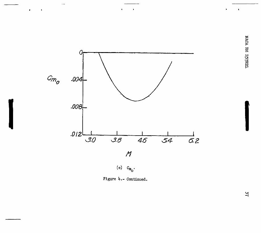
pitching-nozent coelficient at zero angle or’ =%tack
horizontel- ta i l def lect ion for pi tch control
different ia l hor izontal- te i l def lect ion f o r r o l l colltrol
ve r t i ce l - t a i l de f l ec t ion fo r yew control

c - "n a - rb r2s" 2v
Side foxce CY side-force coefficient, us 1

NACA RK L S F 1 5
L
I
b s p a , 22.36 f t
s wing -ea, 200 sq f t
C mem a e r o d y n d c chord, 10.27 f t -
CL l i f t coefficient, - L i f t %is
FI g, r airplane ar?gular veloci t ies &bout the x, y, z body axes
U I VI w a i rp lane l ine ve loc i t ies along the x, y, z body axes
Zi, q, ni direction cosines releting the airplene body exes and space axes ( i = 1, 2, 3)
g &cceleratioo due t o gravity, 32.17 ft /sec2
v to ta l ve loc i ty , @C"T2 Kl rcll-daurper gsin
I<i pitch-dam2er gain
K3 yew-dmper gain

deflection of left side of horizontal tail
deflection of right side of horizontal tail
roll control signal fro= control stick
pitch control signal from control stick
yaw control signal from rudder pedals
oscilloscope display
oscilloscope display
oscilloscope display
oscilloscope display
oscilloscope display
initial condition
signal for horizontal component of wing
signal for vertical comgonent of wing
sigoal for horizontal component of tail
signal for vertical component of tail
sweep frequency, 300 cps
STATEMEPIT OF THE PROBLEM AND DISCUSSION OF S-ION
The objective of this study was to evaluate in a quslitative menner the effect cf the aerodynanic characteristics of the proposed research configurzticn with respect to a pilot's ability to perform a specific control task during e. part of the exit ghase, which includes thrust cut- off, of a tmical high-altitude-flight plan. In addition, it was desired to detemine the trends airplane characteristics should take to ease the control tasks and to determine the effect of infornation display OIL the control task. The flight plan selected was essentially a ballistic trajectory ad, therefore, the control task assigned the pilot was to maintain the Lqgles of attack, roll, yaw, an& sideslip at zero through- cut the flight. The detzils of the slmlatlon, including the equations used, ere presented in the appendix. The siniuletion is swmarized i n the following paragraphs.
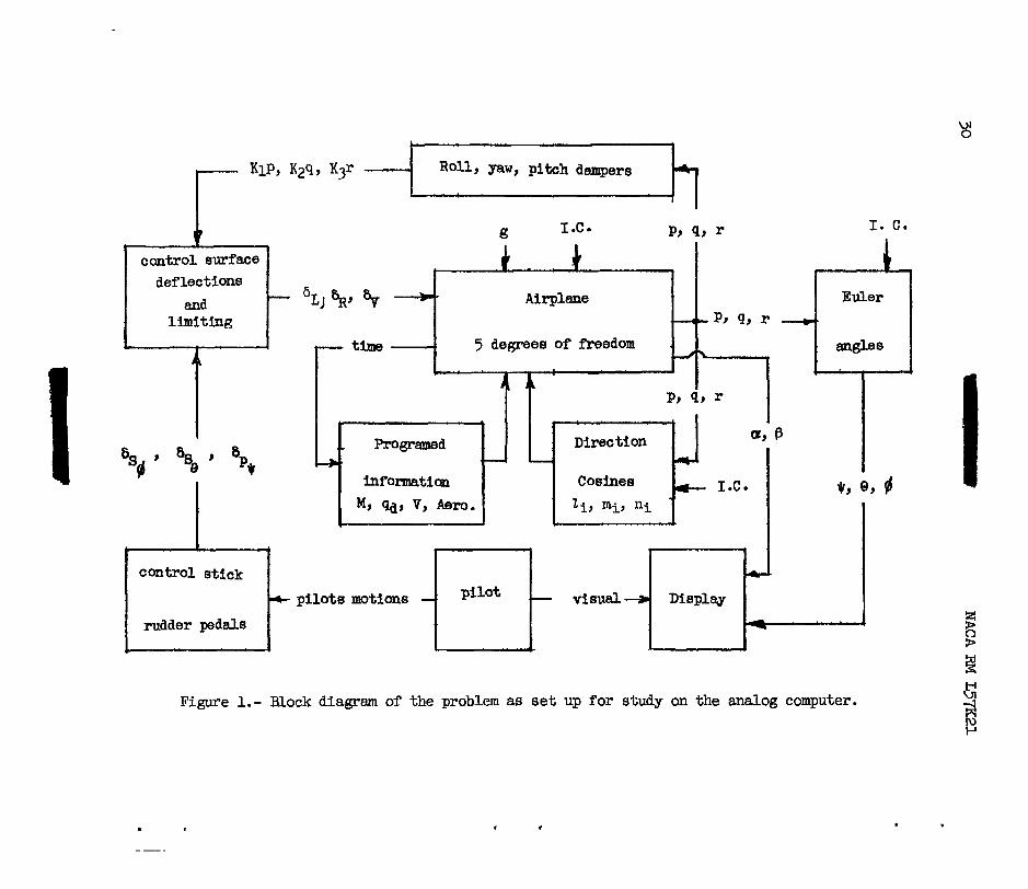
Tigu-?e 1 is a siEplified block diagram of the sinulation that shows infomction flcw . Reference to it shculd be of help in followil.1-g the discussicn cf the simlation. .

7
t
c
The sssuned veriations of Wech nunber, dynan?ic pressure, and a l t i t ude used i n this study are presented in figure 2. Engine cutoff (burnout) has been ar’bitrari ly set a t 83 secords. The part of this figure between the vertical-dashed lines, tbt portion from 55 seconds t o 105 seconds, is the port ior of the f l i g h t slen over which this s tudy was conducted. Fne data ?resected in figure 2 show the wide range of fl tght conditions over which the p i lo t must control the airplsse. The besic parameters, Hach number and dynamic pressure, vaqy fron 3.2 and 350 pounds per square foot t o 5.5 and 20 pounds per square foot, respectively, during the sinulated flight. These variations indicate the t the bas ic s tab i l i ty charac te r i s t ics of the airplane are also subject t o wide variation. As indicated io figure 2, burnout occurs approxi- nately 28 seconds a f te r the stert of the probleE.
In this s tudy, in order to s implify the analog, it was assumed that the Mach number and Ciynanic-pressure variations would be those of the calculated f l igh t ~lan - that is, they would be unaffected by eny of the random motions occurrir-g in the s imula tor f l igh ts . T h i s assut?rp- t i oc ge ra i t t ed the velocity, Mzch nmiber, and Qnamic pressure t o be expressed es functions of the f l ight time. The airplane w a s represen-bed ES a five-Eiegree-of-freedom system w i t h time-verying coefficients (those depecding on Mach number and dynamic pressure). These equations were re fer red to the p r inc ipa l body axes. As the incl inat ion of the principal exis i s very small, the e f fec t of this incl inat ion w a s considered regligible. Progrmed vmietions of mass a d i n e r t i a were also used to account f o r the lazge change i n these quantit ies due t o rocket burning, and the varietions io these pazameters essuned f o r this study are presented in figure 3.
The aero6yxad.c parmeters used were obtained from the unpublished r e su l t s of wird-tunnel tests of an advar-ced research configuration. The s t a t i c s t ab i l i t y de r iva t ives were progrmed as functions of Mech nunber and were assurced to remin constant with angle of a t tack and aagle or” sidesl ip . These variations are shoTm in figures k( a) to 4( f ) . In figure 4(a) the curve labeled Cn is the basic Cn of the airplane
and tha t labeled Cn represents t’le naxinm velue of used. B B
PA CnP Results w i l l be reported f o r both
cnP and In figure three
curves m e presented f o r C . The center curve is the basic C f o r
the airplane and the other two curves bracket the veriations assumed i n the effective-dihedral pa rmte r . The assunptioo of constmt derivatives w i t h angle of atteck is very good; wind-tunnel r e su l t s show these param- e t e r s t o be corstant from 0 t o 9’. Since the assumed f l i g h t plan called for zero angle of attack, it was f e l t that, if the range of angle of gttack where the s tab i l i ty der iva t ives became nonlinem? flrnctions of
2P 28

8 NACA RM ~ 5 7 ~ 2 1 .
angle of attack were entered, it would be only monentarily. Actual s inulatcr runs showed this t o be true, with a rarely exceeding IOo. Tke assmqticn of constent derivatives with angle of s idesl ip was good fo r smll angles of s idesl ig - that is, to t he 5' maxim of the wind- tunnel t e s t s . Since s w c e s s a l f l i g h t s r a r e l y exceeded t'nis value of' s idesl ip , the esswnption is considered satiaf'actory for these simlator tests. Althoxgh no data were available for the rotmy derivatives, provisiom were =de in the setup for their eventual inclusion. The coGtro1-surface-effec%iveness coefficients were not prograued with Mach number s ime da t a were evailable only at M = 3.5. These data are pre- Eented in t ab l e I. The actual zoEents and forces produced by the surfaces were not constant, however, due t o the programed changes in the dynamic presszre.
As noted previomly, rocket burnout occurs dwing the simuletor flight. Eerly rocket airplanes, such es the Bel l X-LA md Bel l X-2 air- plar-es, have been troubled to a lrinor degree by the trim changes a t burnozt caused by thrust miaalicezent suddenly reducing t o zero. Since the proposed tlmst I s roughly four tines that of the B e l l X-2, even nore trcuble could be emected. In order to determine these effects, engir-e th rus t nisa1inen;er;ts were included as cocstm-t nonents i n the yawicg- aad gitching-monent equetions. These mor;.,ents were calculated fron da% given in the engine progress reports ar,d engine specifications and were foznd t o have a mimum value of about 5,000 foot-pounds.
The pi lot ' s contrci s ta t ion consis ted of a seat, control s t ick, and xdder pedals together with an infornation display ( instment panel) . A photogrqh of t h i s s ta t ion i s shown as figure 5 . When i n use, the s t a t i o c was ellclosed i n s. canvas screen so that the p i lo t would not be distracted. The stick and pedal feel forces were scpplied by simple sprir,gs ar_d were, therefore, incependient of Yick: rider or dynanic pressure. Tabie I1 sxmerizes the s t ick and pedal forces and t ravels and the attendant ccntrol-s-arface 6eflections. 13 should be poir,ted out the t Ln the oginicn of the test p i lo t s the forces and mcnents shown La ta3le I1 do not represect good control hamoqr. Some r u s were nade with be t t e r kamony after the investigation had been congleted, and it was found that the Cifferer-ce in control harmony did not .zppreciably affect the resul ts .
The infcmfition display consisted of three t ight ly grouped cathode- ray tukes ( f i g . 5 ) . This disglay was developed a f t e r p r e l i d n a r y t e s t s inCiza%ed a need fo r ra3id scanning by the p i lo t . The de ta i l s of the informatior, c?ispl&,y ere shown i n f igure 6. The center cathode-ray tube presentel! the angle of attack a, the angle of s idesl ip j3, and the r o l l angle $, while +he u2per scope presented heading angle $ and the l e f t one presented gitck? a%titEde 8. Hereinafter, t h i s d i s p h y is referred t c as the 8-$ display. The rrmker used on the center scope was an inverted T which m y be thought cf a s the rear view of an airplane.

9
T” mrker displaced ver t ical ly to present a and hor izonta l ly to show p md rotated about i ts own exis t o show $. The sca les for a end P were approximately 0.1 radim per inch. Ilegative sideslip wes t o t he r i gh t t o d e the disslay coa2atible with f l ight. For the euxiliary scopes, tbe heading w k e r moved horizcntally and the p i tch rarker moved ver t ical ly , bot% ap2roxinately 0.4 radien per inch.
The p-fl display was used f o r most of the investigation. However, some t e s t s were made with a display nore &io t o stadard f l igh t ins t ru- rrents. This d i s p h y was called the att i tude Bisplay end presented pitch a t t i tude 6, heaairg mgle (r, and r o l l angle 6 cn the center scope. The angles of e t tack .md s ides l i s were on the auxiliary scopes. Tne scales for the a t t i tude display were the same as those used on the p-# display.
The pi lot’s display of r o l l a t t i t u d e was set up f o r a moving air- plane ratller than the movi-ng horizon that is used i n most f l igh t ins t ru- ments. TEe use of the moving eirplane ES based on previous experience at the Lengley Labora;tory end 03 %he results of reference I, both of which indicated that, on simulators which do not move t:be p i lo t , the rzoving e i r p l a e is the preferred t n e of display or r o l l a t t i t u d e .
Since the aqg~lar veloci t ies of t he a i rp lme e r e coEputed in body exes, which are .s rotet ing axes system, it was necessary t o t r e n s f e r these variables to spece axes for the display. Equctions ( 9 ) t o (11) of the appendix were used t o d e the conversion.
P. werni-ng l i g h t which came on 3 secords before thrust cutoff (burn- cu t ) was inclaCe6 in the display. This l ight provided the pilot with so= ant ic ipat ioa of the trim changes which cccur at thrust cutoff.
RESULTS A3lD DISCUSSION
Freliminary AmLysis
Pnalyticel investigation.- The l a t e r d end longi tudine l s teb i l i ty of the airplm-e w&s iwes t iga t ea by use of the t’nree-degree-of-freedo= ste’bility equations at several points alollg the selected trajectory. These celculetions shcwed that the basic e i rplane was always l a t e r a l l y unstable .znd that it had gcod longi tudina l s tab i l i ty a t the lower a l t i tude f1Lgi-h conditions and had approxhate ly neut ra l s ta t ic sta- b i l i t y at tine high-altitude flight conditions. The adci-lior of estimated rotary derivetives increesed the stabiliky et the l o w a l t i t udes a d delayed the onset of insta’oility to Eoderate altituCes. Tce effect of %he rotary derivatives at high elt i tude w a s negligible.

10 NACA RkI L57K21 .
The ef fec ts of s t a b i l i t y augmentation were approximated by adding appropriate increEents in the rotary derivatives and C t o t h e
lateral equations and C to the longi tudinal eqLmtions. The addition
of e i ther C and C alone had l i t t l e o r no effect on the Dutch r o l l
node. However, the addition of both resul ted in large improvements i n s t a b i l i t y . I n the longitudinal equations, the addition of pro- duced good s t a b i l i t y throughorrt the flight realm. The values of each of these paramters required to give good s t ab i l i t y a r e summarized fo r the f l ight condi t ions at bmnout as follows:
c4 IP c
ms 4 2P
A C ~ = -221.15
c11: = -2.602 2P
These values give a r o l l damping of T =
d&mpil?g of T1/2 = 0.9 second., and p i tch &sing 1/2
0.5 second, Dutch r o l l of T1/2 = 0.75 second
at a f l i g h t time of 28 secands, the time of thrust cutoff. These values . of the damping derivatives were used to g ive an indication of the damping required crt the sinulator.
Constant Mach number simulator studies.- As ga r t of a p i l o t famil- ia r iza t ion program p r i o r t o making the t ra jec tory fl ights, several f l i g h t s were made at constant Mach number &d al t i tudes. These f l i g h t s were made at a l t i tudes of 84,000 and 180,000 feet , the end points of the t ra jectory. In these flights the pilots attempted to evaluate the s t a b i l i t y and control characterist ics during m e u v e r s . These maneuvers were generally a r e tu rn t o s t r a igh t and l e v e l f l i g h t from i n i t i a l dis- turbances in a and p and constant altitude turns with a bank angle of 45O. A t the low-alt i tude f l ight condition the pilots felt that the basic airplane was extreEely diff icul t to control an& that t o avoid losing control a l l maneuvers had t o be very slow and deliberate. Three- axis damping equivalent t o 50 percent of the damping required for the linear analyses inyroved the handling characteristics under the afore- mentioned conditions. During these simulated piloting tasks the p i lo t s cmplained of apparent low control power i n yaw and ro l l cont ro l . This apparent loss of control power t o t h e p i l o t r e s u l t s because the da~per s are using so much of the available control-surface deflection to correct disturbances that, when the pi lot mves the controls , the a i rplane does not respond t o his ingut. Thus, as the magnitude of t h e a r t i f i c i a l damping i s increased, the apparent control power of the surfaces, as

perceived by the pilot, decreases. A t high altitude fhe response of the bssic airplane was so slow that the p i lo t had no d i f f i cu l ty in maintaining control.
Trajectory Flights
!The procedure used i n these f l igh ts was t o have the p i lo t t r im the airplane at a f light-path -le of 3l.5O as ce l led for by the f l i g h t plan. When trkn conditfons had been established, the pilot f l e w the a i r p k e over the progrmed portion of the flight plen. In these f l igh ts the p i lo t 's task was t o hold a, B, #, and the angular ve loc i t i e s t o zero. Sufficient practice and repea t f l igh ts were nade so thet the p i lo t s were cmgle-lely familiar w i t h the simulator cheracter is t ics .
In interpret ing the resul ts of the investigation made Curing the t ra jec tory f l igh ts , it should be renembered tha t , as the airplane accelerates and c lhbs , the a i rp lane becons l ess stable and the air density decreases. Both these effects increase the periods of the aimlane 's osci l la t ion. The longer periods tend to ease the pilot's control task as long as di rec t iona l ins tab i l i ty does not occur. How- ever, a high degree of e ler tness must be maintained es motions develop very slowly at these high altitudes sad by the t h e the p i lo t de tec ts a &vi&tion fron the desfred condition it may be too la te f o r corrective ac t ion.
Tce first krajectory f l ight w&s nade with the basic airplane and without disturbences - t ha t is, there were no engine thrust nisalioements w-6 no exteroal disturbances were used with respect to the a i rp lane o r p i l o t . The p i l o t was able t o control the simulator and t o complete the f l i g h t ~ l m . However, t he p i lo t s t a t e& tha t he h&d grea t d i f f icu l ty in coatroll ing the si?llule=tor end, because of the extrem concentration required, considere6 airglenes with these cheracterist ics unflyable. The recorded notions of the airplane and of the control stick an& pedals did not show m & u e & i f f i c u l t y . I n o r a r t o demonstrate this concentra- t i on l eve l , f l i gh t s were ma6e i n which an a d d i t i o o d work load wes given the p i lo t . Oae additional work load insposed was the d is t rac t ion of the p i l o t t o tasks other then flying. This was simulated by intercepting the p i lo t ' s view of the display f o r not more than 5 seconds a t different times during the P l i g h t . Another additional work load was the control of engine t h r u s t a s m e t r i e s during burning f l i g h t and resu l tan t trin changes which occur at thrust cutoff. As the ergine thrust asymrretries were constmt, the p+lot, E?S the alt i tude increases, must continuously increase h i s control deflections in order t o cor rec t the ou t -of - t rh conditions. Figure 7 ( a ) shows the effect of the d i s t rac t ion an5 of e vertical thrust nisalinement on t h e p i l o t ' s a b i l i t y t o maintain control of the a i rp lane . men the p i lo t ' s a t ten t ion to the cont ro l t ask was

12 NACA RM L57K21
mmentarily diverted, he lost control of the airplane. As indicated by the sol id curve i n figure 7(a), the addition of a ver t i ca l thrust ais- alinement apparently caxsed the pilot no additional difficulty over and above those associated w i t h the basic a i rplme. However, when a l a t e r a l thrust misalineneot was added, figure 7(b), the p i lo t los t cont ro l of the airplme before burnout. This result substantiates the results of the l inear analysis and constant Mach number f l i g h t s which indicated that the airplane was more sens i t i ve t o lateral disturbances.
ETfect of direct ional stability.- One possible cause of the d i f f i - culty experienced by the p i lo t s can be seen i n figwe &(a), which presents the variations with Hach cumber of t h e s t a t i c lateral s t a b i l i t y param-
eter cnP
in cnP
. Shown are the basic wind-tunnel data and also the other
variations used i n this study. The basic data show that at a Mach number of 4.4 the airplane becomes directionally unstable. This trend
accounts for the buildup in sideslip noted when the p i lo t was distracted. The ro l l ing and pitching Eotions noted were due t o t h e high jd/p r a t i o and the i ne r t i a coupling of the airplane at these f l igh t conditions. An increased C shown in f igure 4( a) as C, , which
made the configmatioo stable throughout the Mach number range considered was also tested. With this increase in C t he p i lo t was able t o minta in cont ro l over the programed par t of the trajectory, even when Eomentarily d is t rac ted o r when thrust misalinements were included. (Ccmpere f ig s . 7 ar,d 8.) It must be noted, however, that ~liany practice f l i g h t s were required before successful f l ights were obtained with any consisteocy. Although it was possible to maintain control, the pilots were of the opinion that an airplane with the characteristics sinulated w a s s t i l l unflyeble.
=P’ PA
nP
Damping studies .- As indicated by botin the l inear analysis and the simulator f l ights, additional damping was required. Investigations were made of both augmentation as obtained fro= control-surface deflections and as increments in the rotary derivatives C C and C I n 4’ 2p’ “s’ the control-surfece-augn-tation cases, the assunption was W e t h a t the surface would deflect proportional to the ang~larr velocity through a perfect servo system. For similar amounts of danping, no difference w a s found between the two types of augmentation; this indicated that the e f fec ts of the mmnts introduced by the cross-control term
and C 2 were small. This result is for the restricted condition of
three-axis damping end small angle of attack. If e i ther of these condi- t ions is not net, the effects of these moaents nay become very inportant as they do when the yaw h p e r is not used.
c%I
6,
The mount of dup ing was systemtical ly increased untfl the p i l o t f e l t the airplane possessed the minimum s t a b i l i t y t o f l y t h e t r a j e c t o r y . As a ster t ing point , damping eguivalellt t o the estimated rotary derivatives was tested. This m o m t of damping had no noticeable effect on the airplane aotions o r the control task.
In t he p i lo t Is o?inion, suf f ic ien t AP_pypir?g was obtained with about one-half of the refereEce values deternined by linear analysis. Fig- ure 9 conpaxes a flight w i t h this amount of three-exis damping and a shi1e.r Plight without damphg. Thrus t niselinenents were includea i n both ccses. It shoald be pointed out that this mmmt of h p i n g was sufficient during the climbing t r a j e c t o r y i n which the F i lo t was not concerr-ed w i t h o ther f l igh t t asks and could concentrate his entire effort on the control tasks. Also, i n t h e s i m l e t o r , %he control system was almost perfect - that is, no s l o ~ ) or lags .I and, fur ther , the g i l o t was not subject to asy random forces or motions. Thus, because of these differences between sinulate8 and a c t u a l f l i g h t ana because the tme of display nay hcve an influence on the em0un-k of da.uiping required, the mgnitudes of denping required lor good s t a b i l i t y a d control determined i n t h i s study are only qual i ta t ive a d based on pi lot ' s oplr ion.
Further increases in augnientation were =de until the dampi% was equivalent to reference values esteblished by the linear eaalysis. The pi lots preferred this dazqing t o lesser amounts but w i t h reservatiom because of the adverse effect of -ping on the response of the airplane t o the pi lot ' s control Inputs . This increase in damping did not affect the aimlane not ions to any noticeable extent, the aMed augmntation lrerely reducillg the work required of the p i lo t .
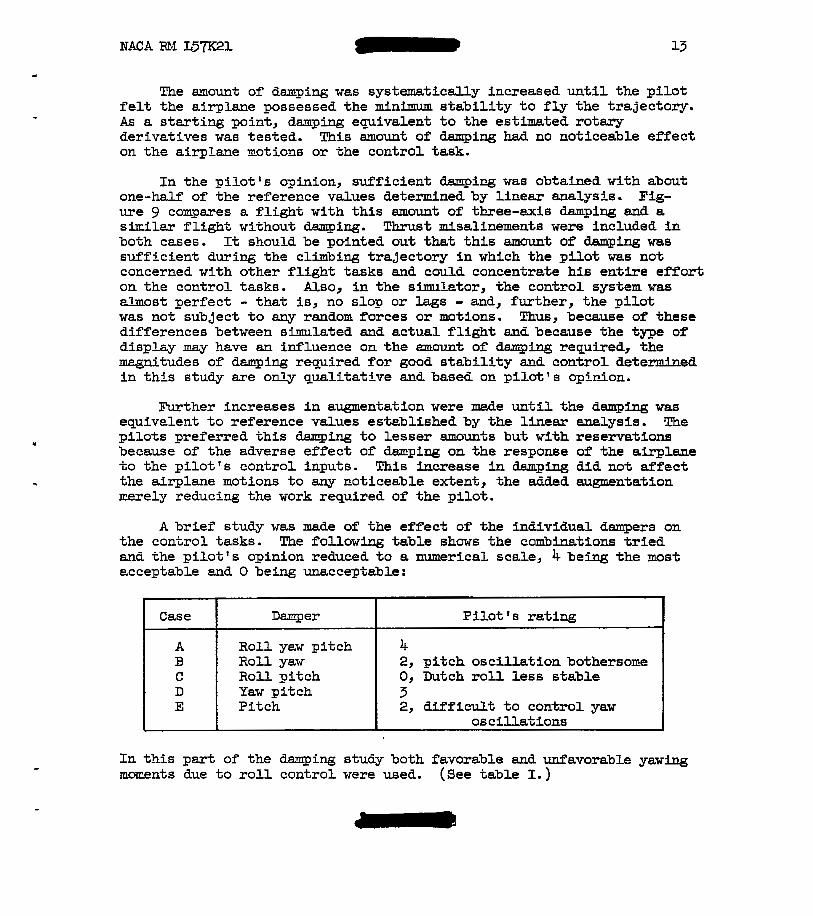
A brier' study w a s nade of the effect of the ineividual dangers on the control tasks. The followiag table shows the combinations tr ied md the pi lot ' s opinion reduced t o a r m r i c a l scale, 4 being the mst acceptable end 0 being unacceptable:
C a s e Dmper
A B
R o l l yaw pi tch
Pi tch E Yaw pi tch D Rol l pi tch C R o l l yaw
P i l o t 's reting I 4 2, p i tch osc i l la t ion bothersoEe 0, Dutch r o l l less stable
2, d i f f i cu l t t o con t ro l yaw
In t h i s p e r t of the daqing s tuw both favorable and unfavorable yawing zoxents due t o r o l l cor-trol were used. (See table I.) -
14 NACA RM L 5 W 1
Wile tbzee-axis dexqing we8 the preferred condition, the pilot f e l t the onission of the ro l l dmper was l e a s t c r i t i c a l . In addition, the p i l o t thought that if the yaw damper fa i led the roll damper should be s h A t off hmediately. It was found tha t the ro l l dmper caused the Dutch r o l l node t o becorce consicerably less s table when the yawing momer,t due to the ro l l ing t a i l def lec t ion was favorable. In this case, the actioc cf the ro l l cont ro l sur faces to damp the rol l ing motion caused a negative t o be introduced which resul ted in a deterioration
of the Dutch r o l l damping. When a yaw damper was used, it counteracted the unfavorable (negative) effect and the Dutch r o l l mode was foud s a t i s f ac to ry by the p i lo t . These resul ts indicate that, when an a i rp lme has low inherent daqing and a favorable yawing moment fro= the roll control surfaces, tke roll damper and rudder should be inter- connected s o that the rudder deflects w i t h the a i le rons to compensate for the unfavorable introduced by use of the a i le rons to oppose the
r o l l .
cnp
cnp
cnp
InasmEch a s the aerodynamic character is t ics of this airplane vary with angle of a t tack, the resul ts of the daTing study are limited t o the smill perturbations about zero angle of a t tack for the aerodynamic chezacter is t ics c i ted in table I and figure 4.
Effect of dihedral parameter Cz .- Another cause of the control
d i f f i cu l ty experienced by the p i lo t was the high ra t io of r o l l t o side- s l i p of the coxfiguration. A contribution to this r a t i o is the rol l ing monent due t o s i d e s l i p C Figure 4(b) presents the variation with
Mach TIullber of this p rame te r fo r the basic configuration of the tests. Also shown are the extrexe negative and 2ositive variations studied. The p i l o t s ' conments on the effects of C 2 can be sllmmnrized as
follcws: Increasing C frorr zero in e i ther the negat ive or posi t ive
direction increased the difTiculty of cont ro l l ing the a i rp lae j however, f o r the range of valxes cf C used the effect of t h i s parameter on the control task was of secodary imsortance.
28
B IP
%
Cor_trol-effectiverss studies.- Because of the lack of comprehensive wind-tunnel data at the tine of programing, the control-surface- effectiveness coefficiellts were assumed t o be constant with Mach nmber. Informt icn now available indicates that the ra t ios used were fair average values with the low value a t M = 3.2 and the high value et M = 5.5.

NACA RM ~ 5 7 ~ 2 1 w 15
..
The di rec t moEents - t ha t is, the momlrts caused by C I CmBh,
md C, - gave adequate control power at the low-altitude pert of the
f l i gh t ; however, a t the high-altitude high hkch = d e r range, the p i l o t f e l t tha t t h e r o l l and yaw control power was very low. The pitching ament provided by the horizontal- ta i l coeff ic ient proved t o be
adequate f o r the task of mintaining zero angle of attcck through the par t of the flight tha t m a s imla ted .
%f
s,
cmg,
The effects of CrOSS-COIItrOlmoments, yaw due t o t h e r o l l control and r o l l due t o the rudder, provided by the coefficiects C
Were d S 0 evalueted. me ro l l ing moljleni; due t o the rudder was larger thEn the rolliIlg monent due t o t h e r o l l i o g tail, and this proved quite ob jec t ionable to the p i lo t un t i l new coordin&tion techniques were learned. After the leazning period the pilots considered the
e f fec t on the control tesk to be secondary t o t h e lack of d i r e c t i o m l s t a b i l i t y End dauging, although they indicated that e. ne=-zero value of this parameter w&s prefereble. The ef fec t of yawing lroIllent due t o r o l l c o c t r o l w e s not es obvious, the pi lot not ic ing l i t t l e or no ef fec t of znegnitude changes and no difference between favorable and unfevoreble velues of C, . The lack of e f fec t of C, on pilot opinion is
caused by the fac t t ha t the colltribution of t o t h e t o t a l yEwing
monent is swll as comared with the contribution of the other parameters.
%P and czgv
c2s,
% l t 6h' c%hl
- However, as previously pointed out, a favorable Cn t en& to nse;ke
%I
the Dutch r o l l node l e s s stable when yaw h p i n g is onitted from the systen.
Tce cross-coEtrol-effectivelress paraneters and C have c"sh 1 2 8 v an effect oa t he ab i l i t y of the r u d k r t o produce a yawing lnonent. When a yewing EoEeot is appl ied to the system and F t is desired to meintain zero sideslip md w i n g s level, the rudder deflection 6, to cancel the asplied moment is giveo by
c

The %ern; in parentheses can be considered the effective yawing-moment coefficient due to ver t ical- ta i l def lect ion. Thus, when Cn and
%' have the sane sign, the effective C, i s smaller than when
4 c and C2 have opgosite signs and, thus, xore rudder deflection %h 1 8,
i s required to cancel the applied yawing moxent. This condition can becoze quite serious when the g i l o t is trying to cont ro l engine thrust asymzetries or large-arrplitude lateral oscillations. Figure 10 i s an i l l u s t r a t i o n of this effect when the s i l o t is trying t o t r i m engine thrust asyzmetries. In th i s case the ruiider power becmes inadequate just before b-;rnout and the p i lo t a lnos t imdia te ly loses cont ro l of the airplane. In t h i s f l i g h t the ahysical stop on the pi lot ' s control was 5O instead of the 6 O indicated in table 11. This discrepancy w-as caused by cea te r ing d i f f icu l t ies in the rudder pedals.
Display stadies.- As previously noted, two different displays vere ased &ring t h i s investigation. One of these was the a-fl display used for the study up to th i s po in t , ir_ which a, p, and fl were 011 a single inverted T marker on the cecter oscilloscoge and 6 and IJI were on auxiliary osc'lloscopes. The second was the att i tude Cisplay which presezted 8 , $, and fl on the center oscilloscope and a and p on tfie auxilimy oscilloscoses. Comparison flights of the displays showed that the pilot. whet usicg the attitude display, found the control task t o be =ore ciiffic-zlt than when using the p-g display. For instance, the effective-dihedrai parmeter which the p i l o t s f e l t t o be of secondazy importance with %he p-g display was found t o be c r i t i c a l l y important with the attltu&e display. Figure 11 compmes the notions of the air- plane for the two information displays. Tnese f l i g h t s were made with She basic airplane modified by increasing C, an& C 'lo the meximm
stable values of figure 4 er-15 rctary derivatives with values of C = -0.2601, C = -11.05, and C = -0.873. ?u'o auxilary dampira
was su2plied. Wen the ettitude display was use&, the a i rp lme motions have large amplitudes and the pilct loses cor, trol of' the airplane just before engine thrust cutcff. WheE the $-fl displey m s used, the aotions have a nuch sxmller anpZitu.de altkough the frequency is about the sane and the p i l o t was abie to roaintain control of the eirplese throughout the fligh?.
B B
2P "s nr
The difference between the two &isplays is in the presentat ion of iryomaticn. The airplme s tudied is characterized by a high @/p r a t i o acd low aileron an5 rxiider power. mese characterist ics require the 2 i io t TO min ta in very clcse cor-trol over en6 t o coorcioate closely the p-g motions of t3e aimlane. Thus, the display t3at presents @ and p by the notLon of a single marker eased the pilot 's task by
reducing the scaaning and data-assinilakioo time w i t h respec t to the nore conventional attitucie display. This reduction of scarnizg md ds t a -a s sh i l a t ion t i ne w a s further decreased by including the rz idi- cator, t%e o ther c r i t i ca l cont ro l parmeter , on the same marker.
This display investigation was l imi ted to the clfmbing p3sse of a high-alt i tude f l ight plan where the specif ic control task w e s t o hold ul p, and @ t o 0. For conditions studied, datg. axrangenent had a large effect on the d i f f icu l ty of the coztrol task. This r e su l t i s corroborated by the sinu1e;tor studies of an en t i r e ly different control task reported in reTerence 2.
Since other flight con6itions w i l l require different control tasks, further investigetiom should be made, including f l ight tests, before a final display arrangement f o r this project is evolved.
The follcwing corclusiors nay be d r ~ w n r e l a t i v e t o the s t a b i l i t y and control proble- of a proposed reseaxch configwation during the exit phase of a high-altitude trazectory. These conclusions are based on pilot-controlled sinulator studies of the airplaae.
The proposed configuretion was considered by the p i l o t s t o be lmflyable beczuse of the extrerre concentration and =ectal effor t required to min ta in con t ro l . It was the pilots’ opinions that di rec t iona l s t a b i l i t y end increased damping about a l l three exes were reqcired before the airplm-e would a t t a i n a ai~imum s t ab i l i t y fo r s a fe f l y ing of the prograned p a t of the t ra jectory. The investfgetion of the effect ive dihedrel showed that t h i s parameter had only a secondary ial”1uence on the control task vhen the B-# disslqr was used, whereas it h d a prFmElry inflcence when E =ore convectional a t t i t ude display was used.
Tce investigation of the e f fec t of individual dmpers on the control task indicated t h a t the r o l l Chaser was t’ne least c r i t i c a l . In addition, i f the der-ivakive of yawing moment due t o the ro l l con t ro l is favorable md t’ne yew dalrper fails, t h e r o l l m e r should be cut off bed ia t e ly . The pi tch dartper, while not c r i t i c a l f r o n e safety aspect, damged an osc i l l s t i on that was bothersome t o the p i l o t m a i n doing so eased the conkrol task.
Tie p i lo t s f e l t that the cross-control-effectiveness coefficients C2 md C, should be kept as smll as poss ib le to ease the control
% %’ task.

- As a re su l t of a limited display investigation it was concluded
tha t instrument deta arrangement can have an irqportant e f fec t on the control task and that fo r t he tests reported herein the display combining together illformatior for angles of attack, sideslip, and r o l l was desir- able. It is suggested that fur ther tests, including f l ight tests, be made t o determine the i n s t m e n t arrangement su i tab le for the entire f l i gh t p l ea of the airplane.
Langley Aeronautical Laboratory, National Advisory Conrmittee f o r Aeronautics,
LElngley Field, Va. , November 5, 1957.
1. Aaon. : Pilo+, Performance With Two Different Attitude Displays. AD No. 82868 (Contract Nom 1076( 00), Dunlap and Associates, k c . , ) h e d Services Tech. Inf'ormation Agency, Doc. Service Center (Dayton, Ohic) , July 1955.
2. Rcscoe, S. N.: Data Presentation and Control Devices. Proc. Syrposim on Frontiers of Man-Controlled Flight, Heinz Haber, ed., Ins t . Transp. and T r d f i c Ehg., Univ. of California, Los Angeles, 1953, PP* 70-74.

NACA IIE.1 L 5 P 1
TRE ANALOG SlNX"'R PROGRAMING
By Robert E. Andrews
INTRODUCTION
This appendix presents the eguations of motion which were sirruleted emi e descr is t ion of the nock cockpit. Also presented is e discussion of the difficult ies encourtered along w i t h sollie of the checks perforred t o ver i fy the sinul&-Lor resu l t s . A conqlete schemkic diagram of the analog s hulakion is shown in figure 12.
The a i r s l a r e was represented by the five-tZepee-of-freedom equations w i t h t i n e - v q i n g c o e f f i c i e n t s . The equetions were wri t ten about the s r inc ipa l body axes end are as follows:

20 NACA X4 L57K21
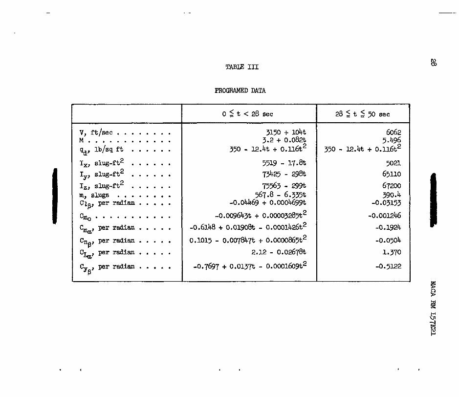
The coefficients of these equations, which are functions of the Mach number and hence the f l i gh t time, are presented i n table 111. These expressions were obtained by f i t t i n g polynomials t o the data presented in figures 2 t o 4.
It w a s necessary t o compute the direction cosines Z3, m3, and n3 so that the gravity forces could be properly included in the airplane representation. The following equations were used
where 2 = -sin eo, = s i n go cos Bo, and n3 = cos pl0 cos 8,. 30 m30 0
PIIDT'S DISPLAY AND METHOD OF CONTROL
The pilot 's control stetion contained oscilloscopes t o display the roll angle, sideslip angle, angle of attack, heading angle, and pitch- a+,titude angle. i+u also contained a conventional center control stick and rudder Pedals. Figure 5 is E. photograph of the control station.
Two different display cmbinations were used during chis investiga- t ion. 'The same inforrfition was displayed i n each but the location -xes different . ?he infomation -vas displayed on a ?-inch du.zl-beem oscil lo- scope i n the form of an inverted T which rotated &bout i t s 0-m axis and also translate6 horizontally end ver t icel ly . Two rectangular oscillo- scopes, each 3 by 13 1 inches were arranged t o show their displays through a mirror. One was mounted i n a ver t ical posi t ion t o the l e f t of the main oscillogcope and the other was mounted horizontally above the main scope.

The first display combination, cal led the p-# display, presented angles of attack, sideslip, and r o l l on the center oscilloscope and the pitch-att i tude and heading angles on the l e f t auxiliary and top auxi l iary oscilloscopes, respectively. Tne inverted T rotates thxough an angle equel t o t h e r o l l m g l e of the a i rplane, c locldse for posi t ive angles . Fne angle of a t tack t rans la tes the T ver t ica l ly , upwerd for posi t ive angles, lihile the engle of s i d e s l i p t r a n s k t e s t h e T horizontal ly , to the le f t fo r Dos i t ive s ides l ip . The displey on the l e f t auxiliary oscil lo- scope presents a horizontal l ine which translates ver t ical ly with the pitch-attitude angle, upward for posit ive engles. The top auxiliary oscilloscope presents a ver t i ca l l i n e which translates horizontally with the heaang angle , to the right for posit ive angles.
The second display cmbination, celled the att i tude dispky, pre- sents the roll angle, beading angle, and pi tch-at t i tude mgle on the main oscilloscope with angle of a t tack end angle of sideslip presented on the side and top auxiliary oscilloscopes, respectively.
The scales Tor angles of a t tack and s ides l ip were approximately 0.1 radian per inch for each display. Tne pitch-att i tude and heading scales were approximately 0.4 rEdi&n per inch for bo-Lh displeys.
Tne angles presented in the display give the pilot the necessary information for orientation with res ect to space as well as with respect t o f l ight path. The N e r angles & 8, a d I$ give the bank angle, pitch-ett i tude mgle, and heading angle, respectively, with reference t o space. The Euler angle equations have been simplified by se t t i ng s in 8 equal t o zero and cos 9 equal t o unity. These equetions are
- a = a, +Jo"(q cos - r s i n $)at
t v = qo +Jo (r cos $d + q s i n d)dt
where 8, = v0 = 0 and a, = 31.3'.
The icvertcd T was genercted by using a dual-beem oscilloscope wlth one be= generating the wing end the okher bem the tai l . For the wing

a sine wave was anplitude-modulated by resolving it by the sine and cosine of the roll angle 8, adding the translating voltage (a, p, 8, or $) t o it, and connecting them t o the horizontal and ve r t i ca l p l a t e of the first bem. The t a i l was generated similarly except th&t a rect i f ied s ine wave was used. For the p-6 display the four inputs to the oscil loscope were
where Wv
wV = a + A s in ut s i n @
WH = -p - A s i n cut cos (d (13)
T~ = a - B s i n ut cos 6
TH = -p - B s i n ut s i n # (15 1
and WH are the signals applied t o the ver t ical and horizont ,a1 p h t e s of the beam producing the wing and TV and % are signals applied t o t h e t a i l beam. B s in a= i s the rect i f ied s ignal from A s in cut. The de ta i l s of t h i s setup are shown i n the schematic arrangement i n figure 12.
‘The pilot’s controls were a conventional center position stick and rudder peikls t o provide aerodynanic controls. Roll control was obtained by the different ia l def lect ion of the horizontal tai l ; thus, it was necessary to combine pi tch and r o l l commands i n the horizontal-tail sur- face deflections. This was done by computing separate deflections for the right and le f t sections of the horizontal t a i l by using the following equations :
6 L ” T - 6 1 + E2 + K1p + K2q
Heading control was obtained by an all-movable vertical surface, and the control deflection i s given by
6v = 63 + K r 3
NACA RM L57I(21 23
A r t i f i c i a l damping is supplied t o the airplane by feeding signals proportional t o t h e anguler velocity to the control surfaces. The terms Klg, $9, and K3r are the demping terns for ro l l , p i tch , and heading, respectively.
The colztrol surfaces were limited in t r a v e l t o +15O and -45O f o r the ro l l ing t a i l and t o ~ i 6 O f o r the rudder. There were no rate IFni-Ls nor l h i t s on the eutopilot authority. The physical properties of the cont ro l s t ick are given i n t a b l e 11.
R burnout m m i n g lamp was included in t he p i lo t ' s d i sp l ay . This lemp was provided t o give the pi lot a warning so that the trim changes tha t occur at burnout could be anticipcted. This I m p came on 3 seconds before burnout and vent out at engine thrust cutoff.
ANALOG PROGRAMING AND CRECKING
A cmplete schenatic diagrm of the analog simulation is shown i n figure 12. Potentiometer settings for the diagram are given in table IV. The to ta l mount of equipment used is es follows:
Amplifiers (total) . . . . . . . . . . . . . . . . . . . . . . . . 102 Integrators . . . . . . . . . . . . . . . . . . . . . . . . . . 15 Summers . . . . . . . . . . . . . . . . . . . . . . . . . . . . 37 Inverters . . . . . . . . . . . . . . . . . . . . . . . . . . . 50
Potentiometers . . . . . . . . . . . . . . . . . . . . . . . . . . 109 Multipliers (shafts) . . . . . . . . . . . . . . . . . . . . . . . 12
PotellL-Liometers . . . . . . . . . . . . . . . . . . . . . . . . . 33 Dual resolvers . . . . . . . . . . . . . . . . . . . . . . . . . . 2 Relay amplifiers . . . . . . . . . . . . . . . . . . . . . . . . . 4
In order t o check the analog setup, s t a t i c and dynamic checks were nade. Several d igi ta l check cases were run also. None of the check cases had any control inputs other than ar t i f ic ia l damping.
For the progrm set up on the simulator, the dynemics of the problem were found t o be near the cri t ical region f o r the computer. Since the computer k-cs t o operate in conjunction w i t h a F i l a t , a real time scale had t o be accepted. In order t o determine the ef fec t of the dymmic er ror introduced by the analog computing elements, especially the servomultic p l i e r s , e d i g i t a l check case without piloted controls was ca lcukted . Runs made with different tine scales on the analog setup showed that m i n g the analog slow by 5:l and 2.5:l comis ten t ly geve the same resu l t s . Rur-s at a 1:l time scale gave differect results, without much

24 0 NACA RM L57K21
consistency. By meticulous choice of variebles to drive the servo- multipliers, the 1:l time-scele runs were made t o check consistently those made at slover time scales. In t h i s par t icular setup to obtain the products n3r, m3p, n p , and pr, the varicbles driving the servo- m l t i p l i e r were changed: m3r from the m3 servo to the r servo, m3p frm the 9 t o the p servo, n p from the n3 to t he p servo, and p r frm the p t o ';he r servo. A comparison of the d ig i ta l ani! analog resul ts for one typical check case is shown Ln figure 13. In t h i s case the only disturbance is the engine thrust misalinement.
An inspection of f igure 13 shows some difference between the f inal amlog setup and "ne digi ta l calculation. In order t o f ind i f t h i s mag- nitu6e of error is wi th in the sensi t ivi ty of the -log equipment, two check cases were =de. For one case the ini t ia l engles of a t tack and s ides l ip were equal t o 0.1 radian, and for the other case both angles were 0.105 radian. It was found tha t this 5-percent difference in input would more than eccomt for the differences in the digi ta l and analog r e su l t s of figure 13 and that final resu l t s sh-ilar t o those of figure 1.3 could be considered reasonable. It was fe l t , however, that w i t h the ava i l ab i l i t y of more servoml t ip l ie rs or i f electronic multipliers hed Seen available, the dynmic error could have been reduced.
Another trouSle spot was the calculation of the direction cosines. Iiere it was found that the s ta t ic nul l ing error of the servomultipliers was important because of the output voltage possible for zero input to the servomultiplier when a large voltage m s fmpressed across the multiplying potent imeter . This was found t o be pa r t i cu la r ly c r i t i ca l i n t he n3p product i n equation (7). Because of the dynamics involved, this product was calculated on the p-mlt i>l ier but bet ter s ta t ic accuracy would resu l t if the product was obtained from a servomultiplier driven by mus, it was necessary that t h i s mltiplying potentiometer be set care- f u l l y on zero. The use of diode-type multipliers may be warranted because of t h e i r good zero output f o r zero-input characteristics and t h e i r good frequency response.
n3
.The s ta t ic s teb i l i ty der iva t ives which were functions of Mach number could be expressed as functions of flight time (see table I11 and f ig . 4) becaGse of the programing of Mach numbers. Terms such as Ctpp and C ~ C L
were ;hen v r i t t en as %he product of a polyrimLa1 i n t and CG or p. As shown in f igure 12, t h i s permits t'ne s t a t i c s t ab i l i t y de r iva t ives t o be generated on servomultipliers driven by t and t2 which are slowly changing variables cmpared w i t h a, and p .
NACA EM L 5 P 1
STARTING Ti ANALOG
In t he check case shown i n figure 13 the motions start abruptly because of the engine thrust misalinement i n p i t c h a t t i t u d e and heading. I n the piloted runs which hsd thrust misalinement, the p i l o t was allowed t o f l y at a constant Mach number u n t i l the misalineEent could be trimmed out. Tie f l ight-plan t ra jectory was then s-lmted. ThFs procedure allowed a snooth controlleci start on the t ra jec tory with the only abrupt change i n trin? occurring at burnout.

26
TABU I
NACA Rii L 5 m 1
CONTROL-SLRFACE-ECI?IVENESS COEFFICIENTS
c z € i h l , per radian . . . . . . . . . . . . . . . . . . . . . -0.0344
, per radian . . . . . . . . . . . . . . . . . . . . . -0.0144 (varied frorn 0.0504
C , per radian . . . . . . . . . . . . . . . . . . . . -0.0172 to -0.0144)
y%t
C Der radian . . . . . . . . . . . . . . . . . . . . -0.2037 yfjv’
C , per radian . . . . . . . . . . . . . . . . . . . . . 0.0527 I s , (or -0.052’7)
C1.sh, per radian . . . . . . . . . . . . . . . . . . . . . -0 344

I
Control
I I
TABLE I1
CONTROL-SURFACE MOVENENTS AND FORCES
St ick Or pedal movement, i n
Hori zont a1
Horizontal-tail roll control
Vert ical t a i l
2.5
4.
1
10
10
50
- ""
I 1
Surface d.ef lect ion, k g
45
24 ( t o t a l )
6
I
V, ft/sec . . . . . . . . M . . . . . . . . . . . . Q, lb/sq f t . . . . . . I,, slug-ft2 . . . . . . Iy, slug-ft2 . . . . . . Iz, slug-ft 2 . . . . . . rn, slugs . . . . . . . . Cia, per radian . . . . . cmo . . . . . . . . . . . C%, per radian . . . . . Cn , per radian . . . . . Ck, per radian . . . . . P
C . per radian . . . . . yB
TAEZE I11
PROGRAMED DATA
0 5 t < 28 sec
3150 + l04t 3.2 + 0 . 0 8 ~
350 - 12 .k + 0.n6t2
- 73425 - 29& 75563 - 29%
$7.8 - 6.335t -0.04&-69 + 0.000469gt
-0.009643t + 0.00003285t
-0.6148 + 0.01908t - 0.0001426t2 0.1015 - 0.007847t + 0.0000865t2
2.12 - 0.02678t
-0.7697 + 0.0137t - 0.0001609t2
28 5 t 5 50 sec
6062 5 496
350 - 12.h + 0.116t2
5023- 65110
67200 390 4
-0 -03153 -0.00124.6
-0.1924 -0.0504 1.370
-0.5122

mcp- RM L57K21
Potentimeter SetiSnz Potentkmeter "
sctt-
.&2
.5ea -700 -700
Cain
i
1 1 1 1 1 1 1 1
10 1
1.82. 1 1 10 1
I.C.
10 1
10 1 1
RecorCer 1 1 5 1 10 1
Recorder 1 4 4
I.C.
1
1 1
1 1 1 1 1 1 1 1 1 1
1
""""
- """"
1 1 -
I.C. I. c .
control surface deflections t limiting and 'LJ ? E l # n IP*i" I
I a, B
I.C.
control stick
pilots motione visual 4 Display
rudder pedala - ,
Figure 1.- Block diagram of the problem as set up for study on the analog computer.
w 0
. ' - "_

"
m I I
k M
I a

NACA RM L57K21
6 x
i 4 X 10³ -
Figure 3.- Assmed vzriations of the moments of inertia and mss with time.

I I I I
” I
.003
: a a l
Figure 4.- Variation of the static stability derivatives wlth Mach number. All stability derivatives are presented per degree variation 0:r u and p.
w w

I”-----
M
(b) CZP’
Figure 4. - Continued.

.u4
03
I a2
Of
0
.
a
M ( 4 “h.
Figure 11. - Continued.

w cn
I 1
0
-, 002
4 0 4
4-6 3.4
M ( a cqy
Figure 4. - Continued.
1 I
. " "-
t
I

"
. C

Figure 5.- Pi lo t ' s control stati.on. L-95262

20°
0
HEADING -20° 0 20°
ANGLE
ATTACK
ANGLE
OF SIDESLIP
Figure 6.- Sketch showing details of information display.
I
I .


42
“ r
- 60 t
(b) Vertical and horizontal thrust misalinements.
Figure 7. - Concluded. -..
.

NACA RM ~ 5 7 ~ 2 1
4 1 -
f
2 -
0
-2 - Thrust niaalfnenents
"""
6 - -Dietraction and thruet miaalineaents
4 -
Burnout
m r
-60 L I I I I I I L 0 10 2c 30 40 50 60
Figure 8.- Pilot control of simulated eirplane with increesed Cnp, of figure &(a) .

44 NACA RM L57K21
Burnout "
w 0"
.L
Q1 ""
-10-
J I I I I I 2 0 10 20 30 40 50 60
time, 8ec
Figure 9.- The effect of three-axis damping on the ability of the pilot to control the airplane.

NACA RM L5"JS21 "
-6 L
time, 8ec
Figure 10.- The effect of C on the ControllabUity of the airplane. %h I

46 NACA RM L57K21
-10 L - - - - ,-- - i p - !d Display
time, sec
Figure 11.- The effect of chemging the display on the control task.

. 4
.
-80ma C 16
80m3 w Bi6
(a) Rolling and pitching circuit.
Figure 12.- Schematic diagram of analog simulation.

(b) Yawing and angle-of -attack circui t .
figure 12. - Continued.
. *

. 1
IOOV -160msr 160n3q
-16n3p 160br
G9 E I7
G3 Dl6
n""" 2O0r E8
2009 65
200q E5
8
(c) hgle-of-sideslip and direction cosine circuit .
Figure 12. - Continued.

" .. A I I C . D"" ""E" - F G - I
2 e c
20
21
-20p F' - - "Y Rec
-2OOq 65 - --. -@
22
Pilot Controls
IOOV 23
200r EB --@ "" Rec
w
ul 0
I (a) Control c i rcu i t .
FIgure 12.- Continued.
. . s

-5OOa
-500a -1008 -ASinwt -28.659 ASinot
-loo$ 50(3B
-loo$ -E Sin wt
B Sin at
-500s
p m e
' 500s
7
f2004 -28659 2ooq
-200r
2OOr
500a 9 - ~ ~ ~ v
3
G 10 629 GI0 629 D3O FI e30 H 13 628 H I3 628 E30
030
G I3
I
I I
I
G I 0
(e) Display circuit .
Figure 12. - Continued.

-
-1oov 32
-
'
33
34
K7ov ' -I/"" 1 To all Differential Relay Amplifiers
I " ..
(r) Function generating circuit.
Figure 12.- Concluded.

2
0 L
L-
r
120 I t \ L
0 I
4 1
8 12 16 20 I L I 1
53
t, sec
Figure 13. - Comparison of malog computer results with digital check cese .
NACA - Langley Field, Vd.