RESEARCH LABORATORY 1v The Effect of Journal … · followed by grinding the as-sprayed surface...
28
NASA/TM--2001-210941 ARL-TR-2467 1 v U.S. ARMY RESEARCH LABORATORY The Effect of Journal Roughness and Foil Coatings on the Performance of Heavily Loaded Foil Air Bearings Kevin C. Radil U.S. Army Research Laborator_ Glenn Research Center, Cleveland, Ohio Christopher DeIIaCorte Glenn Research Center, Cleveland, Ohio June 2001 https://ntrs.nasa.gov/search.jsp?R=20010069210 2018-06-30T22:56:23+00:00Z
Transcript of RESEARCH LABORATORY 1v The Effect of Journal … · followed by grinding the as-sprayed surface...

NASA/TM--2001-210941 ARL-TR-2467
1v
U.S. ARMY
RESEARCH LABORATORY
The Effect of Journal Roughness and Foil
Coatings on the Performance of Heavily
Loaded Foil Air Bearings
Kevin C. Radil
U.S. Army Research Laborator_ Glenn Research Center, Cleveland, Ohio
Christopher DeIIaCorte
Glenn Research Center, Cleveland, Ohio
June 2001
https://ntrs.nasa.gov/search.jsp?R=20010069210 2018-06-30T22:56:23+00:00Z

The NASA ST[ Program Office... in Profile
Since its founding, NASA has been dedicated to
the advancement of aeronautics and spacescience. The NASA Scientific and Technical
Information (STIr) Program Office plays a key partin helping NASA maintain this important role.
The NASA STI Program Office is operated byLangley Research Center, the Lead Center forNASA's scientific and technical information. The
NASA STI Program Office provides access to theNASA STI Database, the largest collection of
aeronautical and space science STI in the world.The Program Office is also NASA's institutional
mechanism for disseminating the results of its
research and development activities. These resultsare published by NASA in the NASA ST[ Report
Series, which includes the following report types:
TECHNICAL PUBLICATION. Reports of
completed research or a major significantphase of research that present the results of
NASA programs and include extensive dataor theoretical analysis. Includes compilations
of significant scientific and technical data andinformation deemed to be of continuing
reference value. NASA's counterpart of peer-
reviewed formal professional papers buthas less stringent limitations on manuscript
length and extent of graphic presentations.
TECHNICAL MEMORANDUM. Scientific
and technical findings that are preliminary orof specialized interest, e.g., quick release
reports, working papers, and bibliographiesthat contain minimal annotation. Does not
contain extensive analysis.
CONTRACTOR REPORT. Scientific and
technical findings by NASA-sponsored
contractors and grantees.
CONFERENCE PUBLICATION. Collected
papers from scientific and technicalconferences, symposia, seminars, or other
meetings sponsored or cosponsored byNASA.
SPECIAL PUBLICATION. Scientific,technical, or historical information from
NASA programs, projects, and missions,
often concerned with subjects havingsubstantial public interest.
TECHNICAL TRANSLATION. English-language translations of foreign scientific
and technical material pertinent to NASA'smission.
Specialized services that complement the ST[
Program Office's diverse offerings include
creating custom thesauri, building customizeddata bases, organizing and publishing research
results.., even providing videos.
For more information about the NASA STI
Program Office, see the following:
• Access the NASA STI Program Home Pageat http://www.sti.nasa.gov
• E-mail your question via the Internet to
• Fax your question to the NASA Access
Help Desk at 301-621-0134
• Telephone the NASA Access Help Desk at301-621--0390
Write to:
NASA Access Help Desk
NASA Center for AeroSpace Information7121 Standard Drive
Hanover, MD 21076 r .
i

NASA/TM--2001-210941
U.S. ARMY
ARL-TR-2467
RESEARCH LABORATORY
The Effect of Journal Roughness and Foil
Coatings on the Performance of Heavily
Loaded Foil Air Bearings
Kevin C. Radil
U.S. Army Research Laboratory, Glenn Research Center, Cleveland, Ohio
Christopher DellaCorte
Glenn Research Center, Cleveland, Ohio
Prepared for the
56th Annual Meeting
sponsored by the Society of Tribologists and Lubrication Engineers
Orlando, Florida, May 20-24, 2001
National Aeronautics and
Space Administration
Glenn Research Center
June 2001

NASA Center for Aerospace Information7121 Standard Drive
Hanover, MD 21076
Available from
National Technical Information Service
5285 Port Royal Road
Springfield, VA 22100
Available electronically at http: //gltrs.grc.nasa.gov/GLTRS

The Effect of Journal Roughness and Foil Coatings on the
Performance of Heavily Loaded Foil Air Bearings
Kevin C. Radil
U.S. Army Research LaboratoryGlenn Research Center
Cleveland, Ohio 44135
Christopher DellaCorte
Glenn Research Center
Cleveland, Ohio 44135
Abstract
Foil air bearing load capacity tests were conducted to
investigate if a solid lubricant coating applied to the
surface of the bearing's top foil can function as a break-in
coating. Two foil coating materials, a conventional soft
polymer film (polyimide) and a hard ceramic (alumina), were
independently evaluated against as-ground and worn (run-in)
journals coated with NASA PS304,
a high-temperature solid lubricant composite coating. The
foil coatings were evaluated at journal rotational speeds of
30000 rpm and at 25°C. Tests were also performed on a foil
bearing with a bare (uncoated) nickel-based superalloy top
foil to establish a baseline for comparison.
The test results indicate that the presence of a top
foil solid lubricant coating is effective at increasing the
load capacity performance of the foil bearing. Compared
to the uncoated baseline, the addition of the soft polymer
coating on the top foil increased the bearing load
coefficient by 120% when operating against an as-ground
journal surface and 85% against a run-in journal surface.
NASA/TM--2001-210941 1

The alumina coating increased the load coefficient by 40%
against the as-ground journal but did not have any affect
when the bearing was operated with the run-in journal. The
results suggest that the addition of solid lubricant films
provide added lubrication when the air film is marginal
indicating that as the load capacity is approached foil air
bearings transition from hydrodynamic to mixed and boundary
lubrication.
Introduction
Compliant foil air bearings operate by generating a
self-acting hydrodynamic air film between the stationary
inner top foil and the surface of the rotating shaft.
Because ambient air functions as the lubricant, foil
bearings do not have the same speed and temperature
limitations imposed on oil lubricated rolling element
bearings and, therefore, can be used at extreme temperatures
(to 650°C) and speeds well above 3 million DN (ref. I). To
capitalize on these advantages, research is underway to
incorporate compliant foil air bearings into high-speed
rotating machinery such as turbochargers, auxiliary power
units (APU's), and gas turbine engines (ref.2).
The rotor-bearing system proposed for several high
temperature, oil-free applications consists of state-of-the-
art foil bearings coupled with rotors coated with a wear
resistant solid lubricant composite coating, NASA PS304.
The foil bearings belong to the Generation III class of foil
NASA/TM--2001 - 210941 2

air bearings and have demonstrated in load capacity tests an
empirical load coefficient, _, equal to 1.0 based on the
Rule Of Thumb (ROT) model proposed in reference 3. The
PS304 solid lubricant coating's purpose is to reduce the
sliding wear and friction that occurs on the top foil and
rotor during start-up and shutdown in the absence of an air
film (refs 4 and 5). Endurance test results from start-stop
cycles indicate that the coating provides bearing wear lives
well in excess of requirements for turbomachinery
applications (ref 6).
Recent room temperature load capacity tests performed
in the authors' lab on Generation III bearings and PS304
coated journals have exhibited load coefficients of 0.3
instead of 1.0 as previously measured. An ensuing
investigation determined that the discrepancy resided with
the journals, specifically, the surface finish of the PS304
coating.
In both series of load capacity tests that resulted in
= 1.0 and _ = 0.3 the journals were prepared identically
by first applying the PS304 material using plasma spraying
followed by grinding the as-sprayed surface with a 500 grit
diamond wheel to a final average surface roughness of 0.8_m.
However, the earlier tests that exhibited high load capacity
(7 = 1.0) were conducted with the same PS304 coated
journals that were previously subjected to high temperature
NASA/TM--2001-210941 3

endurance stop-start cycles. This is important for three
reasons.
First, repeated high temperature rubbing associated
with each start-stop cycle polishes the surface of the as-
ground coating and generates a thin oxide layer that is
smooth, dark, glossy and functions as a solid lubricant.
Measurements on this run-in surface (i.e., oxide layer)
with a profilometer confirm that the rubbing wear cycles
decreased the initial average roughness of the as-ground
coating surface from 0.8_m to 0.05-0.2_m, very close to the
0.05-0.1_m range considered for optimum bearing performance.
Second, it is believed that the localized start-stop rubbing
may also generate better conforming surfaces between the
bearing top foil and the coating surface. Third, the high
temperature sliding causes a transfer of solid lubricants
from the PS304 shaft coating to the top foil thereby
producing a solid lubricant film that leads to good bearing
performance (ref. 7).
An investigation into the cause of the 0.8_m surface
finish of the as-ground PS304 coating identified voids, i.e.
porosity, created in the coating during the plasma spray
process. The presence of open pores typically leads to an
unfavorable surface finish when standard grinding techniques
are used. For example, as mentioned previously, machine
grinding the as-sprayed coating with a 500 grit diamond
wheel results in an average surface finish of approximately
NASA/TM--2001-210941 4

0.8_m. The average surface finish can be improved to
.l-.2_m by following the initial grinding with a more
elaborate process of using 600 grit sandpaper, 9-15_m
diamond paste and 0.008_m alumina. However, these
additional steps are time consuming and costly.
The concern for the surface finish of the PS304 coating
is warranted due to its connection with a phenomenon known
as galling. Referred to as scuffing or scoring in the
internal combustion engine community galling is a failure
mechanism characterized by the formation of asperity
microwelds between surfaces in sliding contact. It is
believed that galling of the top foil and the nickel
constituent in the coating is playing a role in limiting
load capacity in the same way severe galling between piston
rings and liners leads to engine seizure.
The susceptibility of a foil bearing to galling stems
from its reliance on a very thin film of air, nominally 5um
under normal operating conditions, that separates the top
foil and shaft surface. If the average surface finish of
the rotor coatlng is on the same order of magnitude of the
air film a load less than the bearing's designed load
capacity will instigate local asperity contact with the top
foil, resulting in hot spots, friction welding, and galling.
The high asperities can also prevent full separation of the
top foil from the rotor surface resulting in a bearing
NASA/TM--2001-210941 5

operating in a mixed lubrication regime. In either case
galling will occur once contact is initiated.
Ruscitto et al. proposed another explanation for the
relationship between surface roughness and foil bearing load
capacity over twenty years ago (ref. 8). In their report
they speculated that rough surfaces contain relatively large
microscopic voids that provide alternate paths of escape for
the air molecules that otherwise would be used to generate
and sustain the hydrodynamic air film. This explanation is
plausible but is not relevant to this situation because the
pores in the PS304 are not interconnected and probably do
not assist in any additional or parasitic leakage of air.
Even though galling can transpire at any time, given
the right conditions, its most pronounced affect on bearing
load capacity will be while the coating is in the as-ground
condition. Therefore, until the coating and bearing
experience the required number of high temperature start-
stop cycles to produce the thin oxide layer, generate
conforming surfaces, and build-up a lubricious transfer film
on the top foil galling must be alleviated in order to
insure maximum performance of the foil bearing.
The purpose of this paper is to report on a possible
solution to sustaining the designed load capacity of a foil
bearing while using PS304 in an as-ground condition. The
concept to be evaluated is to place a coating directly onto
the top foil to inhibit galling and thus allowing the foil
bearing to support its designed maximum load. Two coatings,
NASA/TM--2001-210941 6

a soft polymer (polyimide) and a hard ceramic alumina, were
chosen for the study. Their effectiveness was evaluated by
conducting a series of room temperature load capacity tests
on foil bearings with coated top foils against ground and
run-in PS304 coated journals. Room temperature was selected
as the best test temperature because it presents the most
severe galling condition and does not prompt oxide formation
on the surface of the coating. To establish a baseline,
uncoated top foils were also tested under the same
conditions.
Experimental Apparatus/Procedure
Foil Bearings
The Generation III class foil bearings used in the
tests are shown in figure 1 and are nominally 35 mm in
diameter, 25 mm long (or wide) and made up of several layers
of nickel-based superalloy foils. The top foil supports the
hydrodynamic gas film while the underlying foils, known as
bump foils, provide the elastic and compliant support
structure for the top foil. The bump foils also provide
Coulomb damping to the bearing through frictional micro-
sliding with the top foil and adjacent surfaces. There are
other foil bearing designs in commercial use that utilize
overlapping leaves and perforated spring foils. The results
presented in this paper should also be relevant to these
different designs.
NASA/TM--2001-210941 7

Test Journals
The test journals shown in figure 2 are nominally 35 mm
in diameter, 84 mm long and made from a nickel-based
superalloy. The journal is an improvement over the previous
two-piece design that used a heat dam and test journal
secured with a tie bolt (ref. 9). The new journal
eliminates the need for a tie bolt by combining the heat dam
and test journal into one part. This provides a 40% weight
savings and a more rotordynamically stable test rig. A
0.25 mm deep undercut is machined on the journal to
accommodate the deposition of the PS304 solid lubricant
coating. The journals have twelve equally-spaced threaded
holes for in-place, high-speed, dynamic balancing.
For the tests with run-in journals, i000 start-stop
endurance cycles under a 10kPa load at 538°C were completed
using an identical Generation III bearing that was not
associated with the tests. This separate bearing was used
to avoid the development of a lubricious transfer film on
the three test top foils or to generate conforming surfaces.
Therefore, any differences in load capacity results reflect
changes in the PS304 coating surface finish and perhaps
chemical composition and/or the presence of the top foil
coating
Top Foil Coatings
The polymer (polyimide) and ceramic (alumina) coatings
were applied to the bearing top foils prior to installation
and assembly of the bearing. The polymer material is a
NASA/TM--2001-210941 8

commercially available polyimide based dry film lubricant
that provides a low coefficient of friction, excellent
adhesion and resiliency and long wear life. The top foil
was coated by spraying the polymer with an atomizer gun to
a final thickness of 25.4 _m and cured according to the
manufacturer's directions.
The alumina was applied to the top foil using a
sputtered deposition to produce a coating thickness of
25.4 _m according to the procedures described in reference
i0. This material was chosen because it demonstrated
promising lubricating properties during previous partial-arc
bearing endurance tests (ref. ii) and also high temperature
rigid gas bearing tests (ref. 12).
Test Apparatus/Procedure
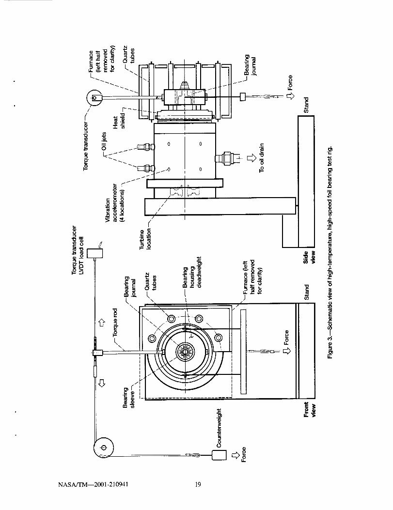
The high-speed test rig used to conduct the tests is
shown in figure 3 and is described fully in reference 9.
The rig consists of a drive shaft that is supported by two
hybrid ceramic ball bearings that are lubricated by oil jets
and cooled by temperature controlled water. An impulse
turbine attached to the drive shaft is capable of driving
the shaft to rotational speeds up to 70000 rpm. Referring
to figure 4, radial loading of the bearing is accomplished
via a vertical cable system with one end attached to the
bearing and the other to a pneumatic load cylinder mounted
below the test rig. A rod attached to the bearing loader
is used to relay the bearing torque to a load cell.
NASA/TM--2001-210941 9

Testing commenced by first placing the bearing on the
journal and then accelerating the rig to a rotational speed
of 30000 rpm. The speed was held constant for a few minutes
in order to thermally stabilize the test rig. A chart
recorder continuously monitored and displayed the bearing
torque signal and the shaft rotational speed. The rig was
then accelerated by a few thousand rpm and the pneumatic
load cylinder was used to apply a starting load equal to
half of the expected load capacity according to the ROT
model. When the desired load was reached the rig was
decelerated to the final speed of 30000rpm and held for
5 minutes unless there were indications of bearing failure.
In this paper foil bearing load capacity is defined
as the maximum load supported by the bearing while still
operating at constant speed and steady-state conditions.
The chart recorder output shown in figures 5 and 6 better
elucidate this definition of load capacity. The two traces
in figure 5a represent speed and torque output from a
bearing supporting a moderate load and operating in a stable
condition. The spikes in the torque data are caused by
sporadic noise from the data acquisition system. Conversely,
the speed and torque traces shown in figure 6 reflect a
bearing operating close to its maximum load capacity. The
erratic behavior exhibited by these traces is indicative of
intermittent surface asperity contact between the top foil
and the coating. While operating at this load condition
frequent speed corrections, in response to the fluctuating
NAS A/TM--2001-210941 10

bearing torque, were needed in order to maintain the test
speed of 30000 rpm.
If failure didn't occur the speed of the test rig was
again increased by a few thousand rpm and an additional 22 N
(5.0 Ib) was applied. The rig speed was reduced to 30000 rpm
and the load sustained for another 5 min. This methodology
of loading the bearing in 22 N (5.0 Ib) increments with
5 min. hold periods was continued until speed and torque
readings indicated that the hydrodynamic film was beginning
to rupture. When this occurred the load was returned to the
previous stable test condition and a smaller load increment
of 4.4 N (i ib) was used.
Test Results and Discussion
The test results for the various top foil coating
conditions are summarized in Table i. It is clearly evident
from the data that the top foil coatings and the PS304
surface finish, either separately or in combination, have a
direct effect on the load coefficient of a foil bearing.
The as-ground PS304 coating, vulnerable to galling because
of its high surface roughness and exposed nickel
constituent, consistently produced the lowest load
coefficients. The baseline bearing's load coefficient of
7 = 0.33 falls significantly short of the '7 = 1 design
point for the Generation III class foil bearings thus
initiating the present research (on foil break-in coatings).
The two candidate break-in coatings tested in this
study, alumina and the soft polymer, exhibited anti-galling
NAS A/TM--2001 - 210941 11

characteristics when paired with the as-ground coating but
at varying degrees of effectiveness. Alumina's presence on
the top foil increased the load coefficient 40% from 0.33 to
0.47. The polymer coating's effect on the load coefficient
was more pronounced than the alumina as it expanded the
margin over the baseline by 120%, from 0.33 to 0.73.
The polymer's superior performance may classify it
as a better anti-galling agent but it is believed that a
significant portion of the coefficient's increase is due to
the polymer's solid lubricant properties. When operating
the bearing close to its load capacity the air film is
marginal indicating contact between surface asperities.
During sliding contact minute wear particles are generated
and introduced into the air film causing a transition from
a purely hydrodynamic bearing to one that may also be in a
state of quasi-hydrodynamic powder lubrication as explained
by Heshmat(13). Based on this assumption, the small
increase in the load coefficient caused by the alumina
coating is probably an indication that, for this
application, it is a less effective solid lubricant.
The tests also demonstrated that PS304 in the run-in
condition plays a major role in defining the load
coefficient of a foil bearing. When the baseline foil
bearing was tested against the run-in PS304 coating the load
coefficient improved 70% over the as-ground result from
= 0.33 to _ = 0.56. The run-in shaft coating had the
same effect on the bearing with the alumina coated top foil
NASA/TM--2001-210941 12

as it increased the coefficient 21%, from _ = 0.47 to
=0.56 but, when compared to the baseline, the alumina
coating was inconsequential as both exhibited coefficients
of 0.56. Continuing the trend when paired with the run-in
shaft coating the foil bearing with the polymer coating
realized a 43% load coefficient increase from 7 = 0.73 to
= 1.05. If run-in results for the polymer and baseline
are compared there is an 85% increase, from _ = 0.56 to
= 1.05, in the load coefficient caused by the coating's
ability to perform as a solid lubricant.
The success of run-in PS304 at improving the foil
bearing's load coefficient can be attributed to the presence
of the thin complex oxide/lubricant surface layer formed
during the high temperature sliding cycles of the stop-start
endurance tests. The oxide layer alleviates the galling
failure mechanism by separating the nickel constituent from
the top foil and its smooth surface finish allows for a much
thinner air film to be tolerated. Furthermore, as with the
polymer coating, the oxide layer produces minute wear
particles that act as a solid lubricant. However, based
upon the baseline and alumina coating results, achieving a
coating surface as smooth as the oxide layer does not
automatically guarantee an adequate bearing load
coefficient. Other additional factors such as the formation
of a lubricious transfer film on the top foil and generating
NASA/TM--2001-210941 13

conforming surfaces through high temperature start-stop
cycles appear to be essential for optimum bearing
performance.
The test results of the polymer and alumina coatings
against the as-ground surface suggests that top foil
coatings can be used to increase bearing performance by
inhibiting the onset of galling. However, it is evident
from the polymer coating results that if high temperature
foil break-in coatings are to be used they must possess
anti-galling and solid lubricant properties. Also, since
the PS304 coating surface finish plays a major role in the
performance of a foil bearing, concurrent work is needed on
improving application and/or surface preparation methods.
Conclusions
i. The current practice of using plasma spraying to
apply the PS304 composite results in a porous coating
that limits the load coefficient of foil bearings.
Further research is needed to identify alternate
deposition techniques that produce higher density
coatings.
2. The test results for the polymer and alumina coatings
indicate that break-in foil coatings that inhibit
galling can, at varying degrees, increase the bearing
load coefficient. Coatings that possess solid
lubricant properties further increase the load
coefficient by providing a solid lubrication
NASA/TM--2001-210941 14

component when the bearing is operating under
boundary and mixed lubricating conditions.
3. To maximize performance, foil bearings operating
against PS304 coated shafts together must undergo
high temperature start-stops in order to produce the
smooth oxide layer, conforming surfaces, and the
lubricious transfer film on the beating's top foil.
References
i. Heshmat, H.: "Advancements in the Performance of
Aerodynamic Foil Journal Bearings: High Speed and Load
Capability," ASME Jour. Of Trib., Vol. 116, pp. 287-
295, April, 1994.
2. Heshmat, H., Walton, J.F., DellaCorte, C., and Valco,
M.: "Oil-Free Turbocharger Demonstration Paves Way to
Gas Turbine Engine Applications," Presented at the ASME
International Gas Turbine and Aeroengine Congress and
Exhibition, Munich, Germany, May 8-11, 2000, Paper No.
2000-GT-620.
3. DellaCorte, C., and Valco, M.J.: "Load Capacity
Estimation of Foil Air Journal Bearings for Oil-Free
Turbomachinery Applications," Tribology Transactions,
Vol. 43, 2000, pp. 795-801.
4. DellaCorte, C., and Edmonds, B.J.: "Preliminary
Evaluation of PS300: A New Self-Lubricating High
Temperature Composite Coating for Use to 800°C, " NASA
TM-I07056, 1995.
NASA/TM--2001-210941 15

5. DellaCorte, C., and Fellenstein, J.A.: "The Effects of
Compositional Tailoring on the Thermal Expansion and
Tribological Properties of PS300: A Solid Lubricant
Composite Coating," NASA TM-I07332, 1996.
6. DellaCorte, C., Valco, M.J., Radil, K.C. and Heshmat,
H.: "Performance and Durability of High Temperature
Foil Air Bearings for Oil-Free Turbomachinery," NASA
TM-2000-209187, 1999.
7. DellaCorte, C.: "The Evaluation of a Modified Chrome
Oxide Based High Temperature Solid Lubricant Coating
for Foil Gas Bearings." NASA TM-1998-208660, 1998.
8. Ruscitto, D., McCormick, J. and Gray, S.: _Hydrodynamic
Air-Lubricated Compliant Surface Bearing for an
Automotive Gas Turbine Engine. I - Journal Bearing
Performance." NASA CR-135368, April, 1978.
9. DellaCorte, C.: _High Speed Test Rig for Use to 700°C
and 70,000 rpm." NASA TM-I07405, 1997.
i0. Lei, J.F.: "Advances in Thin Film Sensor Technologies
for Engine Applications", ASME Paper No. 97-GT-458,
1997.
ii. DellaCorte, C., Fellenstein, J.A. and Benoy, P.A.:
_Evaluation of Advanced Solid Lubricant Coatings for
Foil Air Bearings at 25 and 500°C. " NASA TM-1998-
206619.
12. Murray, S.F.: "Research and Development of High
Temperature Gas Bearings. Volume II: Selection and
NAS A/TM--2001-210941 16

Evaluation of Gas Bearing Materials in Argon at 900°F
13.
and 1400°F ", NASA Contract No. NAS3-9433, 1969.
Heshmat, H.: "The Rheology and Hydrodynamics of Dry
Powder Lubrication." Tribology Transactions, Vol. 34,
1991, pp. 433-439.
Table i. Bearing load coefficients for coated foils running
against PS304 in the ground and run-in condition.
Foil Coating
Soft Polymer
Foil Coating
Roughness,
sum Ra
Load Coefficient,
As-ground,
0.90
PS304
0.73
Run-in,
PS304
1.05
Ceramic(Alumina) 0.15 0.47 0.56
Bare (Baseline) 0.I0 0.33 0.56
Beadngsleeve _ _
Figure 1 .-Schematic of Generation III foil air bearing.
NASA/TM--2001-210941 17

250-Fm thick PS304 coating applied--
29
35diam
\'---1 of 12 set Screw balancing holes
8
CD-00-80986
Figure 2.-Schematic of the modified test journal for the high-temperature, high-speed foilair bearing test rig. Measurements in mm.
......... =_ _. g ::( ;;
NASA/TM--2001-210941 18
/
(
e'l
Q,l
__ i.... Fi.-i._r']i.--,
0 __
_CJJ/
>_ /¢
_.__
_m
0I.L
o o i{_ _:-:..0
....-'i ,_,:;__ I
I
t
•..I m
l' i_-_ ._<,,
;i,,,i °:°1
i
,\
)
/-
LI. ,1_
J/
/
I
I
!8
0L_
"0
"0
ii
-r-
O_e"
m
1ca.
r-
r-
!E
r.,
o
4)>
r_.m
Eq)r.
-s
U..
NASA/TM--2001-210941 19

[
@<
Counterweightpreload
>
i- Deadweight
4Cable
housing
Spring pack
3 _strain gage load cell
Torque transducerLVDT load cell
• • •
Pneumatic load cylinder
Figure 4.--Test rig partial front view showing torque and load measurement
system.
NASA/TM--2001-210941 20

40
Oo 30T =,
x
E 2O¢_
(9100,,
0
(a)
[
i
0 1O0 200 300 400 500 600
Time, seconds
2O
EE 15
Z
L_
0P" 5
0
0 100 200 300 400 500 600
(b) Time, seconds
Figure 5.--Graphs illustrating a foil air bearing operating in a stable condition at 30 000 rpm
and supporting half of its load capacity. (a) Speed. (b) Torque.
NASA/TM_2001-210941 21

A4°Ioo 30T,,=
xE 20i_
o.1000
0
0 100 200 300 400
Time, seconds
500 60(
180
160
140
EEl20100
=;80
O"L_o 60
1-40
20
0
(b)
0 100 200 300 400 500 600
Time, seconds
Figure 6.--Graphs illustrating the erratic behavior of a foil air bearing operating at 30 000 rpm
and supporting close to its load capacity. (a) Speed. (b) Torque.
NASA/TM--2001-210941 22


REPORT DOCUMENTATION PAGE Form ApprovedOMB No. 0704-0188
Publicreportingburdenfor thiscollectionofinformationIs estimatedtoaverage1 hourper response,includingthetimefor reviewinginstructions,seamhingexistingdatasoumes,gatheringandmaintainingthedataneeded,andcompletingandreviewingthe collectionof information.Sendcommentsregardingthisburdenestimateor anyotheraspectofthiscollectionofinformation,includingsuggestionsforreducingthisburden,toWashingtonHeadquadersServices,Directoratefor InformationOperationsandReports,1215JeffersonDavisHighway,Suite 1204,Arlington,VA 22202-4302,and tothe Officeof ManagementandBudget,PaperworkReductionProject(0704-0188),Washington,DC 20503.1. AGENCY USE ONLY (Leave b/ank) 2. REPORT DATE 3. REPORT TYPE AND DATES COVERED
June 2001 Technical Memorandum
4. TITLE AND SUB_i/LE
The Effect of Journal Roughness and Foil Coatings on the
Performance of Heavily Loaded Foil Air Beatings
6. AUTHOR(S)
Kevin C. Radii and Christopher DellaCorte
7. PERFORMING ORGANIZATION NAME(S) AND ADDRESS(ES)National Aeronautics and Space AdministrationJohn H. Glenn Research Center
Cleveland, Ohio 44135-319Iand
U.S. Army Research LaboratoryCleveland, Ohio 44135-3191
9. SPONSORING/MONITORING AGENCY NAME(S) AND ADDRESS(ES)
National Aeronautics and Space Administration
Washington, DC 205464)001and
U.S. Amay Research LaboratoryAdelphi, Maryland 20783-1145
5. FUNDING NUMBERS
WU-708-18-13--00
ILl61102AH45
8. PERFORMING ORGANIZATIONREPORT NUMBER
E-12794
10. SPONSORING/MONITORINGAGENCY REPORT NUMBER
NASA TM--2001-210941
ARL-TR-2467
11. SUPPLEMENTARY NOTES
Prepared for the 56th Annual Meeting sponsored by the Society of Tribologists and Lubrication Engineers, Orlando,
Florida, May 20-24, 2001. Kevin C. Radii, U.S. Army Research Laboratory, Glenn Research Center, Cleveland, Ohio,
and Christopher DellaCorte, NASA Glenn Research Center. Responsible person, Kevin C. Radil, organization code 5960,
216--433-5047.
12a. DISTRIBUTION/AVAILABILITY STATEMENT 12b, DISTRIBUTION CODE
Unclassified - Unlimited
Subject Category: 23 Distribution: Nonstandard
Available electronically at htto://dtrs.m-c.nasa._ov/GLTRS
This publication is available from the NASA Center for AeroSpace Information, 301-621_)390.13. ABSTRACT (Maximum 200 words)
Foil air beating load capacity tests were conducted to investigate if a sofid lubricant coating applied to the surface of the
hearing's top foil can function as a break-in coating. Two foil coating materials, a conventional soft polymer film
(polyimide) and a hard ceramic (alumina), were independently evaluated against as-ground and worn (run-in) journals
coated with NASA PS304, a high-temperature solid lubricant composite coating. The foil coatings were evaluated at
journal rotational speeds of 30 000 rpm and at 25 °C. Tests were also performed on a foil bearing with a bare (uncoated)
nickel-based superalloy top foil to establish a baseline for comparison. The test results indicate that the presence of a top
foil solid lubricant coating is effective at increasing the load capacity performance of the foil bearing. Compared to the
uncoated baseline, the addition of the soft polymer coating on the top foil increased the beating load coefficient by
120 percent when operating against an as-ground journal surface and 85 percent against a run-in journal surface. The
alumina coating increased the load coefficient by 40 percent against the as-ground journal but did not have any affect
when the bearing was operated with the run-in journal. The results suggest that the addition of solid lubricant films
provide added lubrication when the air film is marginal indicating that as the load capacity is approached foil air bearings
transition from hydrodynamic to mixed and boundary lubrication.
14. SUBJECT TERMS
Foil gas beatings; Coating; Tribology; Solid lubricant
17. SECURITY CLASSIFICATIONOF REPORT
Unclassified
18. SECURITY CLASSIFICATIONOF THIS PAGE
Unclassified
NSN 7540-01-280-5500
19. SECURITY CLASSIRCATIONOF ABSTRACT
Unclassified
15. NUMBER OF PAGES28
16. PRICE CODE
20. LIMITATION OF ABSTRACT
Standard Form 298 (Rev. 2-89)Prescribedby ANSI Std. Z39-18298-102