Research Article Synthesis and Characterization of Uniform ...
9
Research Article Synthesis and Characterization of Uniform Spherical Nanoporous TiO 2 Aerogel Templated by Cellulose Alcohol-Gel with Enhanced Photocatalytic Activity Zhiming Liu, 1 Peng Wu, 1 Shaoli Yang, 1 Haiying Wang, 1 and Chunde Jin 2 1 Northeast Forestry University, Harbin 150040, China 2 Zhejiang Agriculture and Forestry University, Hangzhou 311300, China Correspondence should be addressed to Zhiming Liu; [email protected] Received 3 March 2016; Accepted 26 April 2016 Academic Editor: Zhouyang Xiang Copyright © 2016 Zhiming Liu et al. is is an open access article distributed under the Creative Commons Attribution License, which permits unrestricted use, distribution, and reproduction in any medium, provided the original work is properly cited. e spherical nanoporous TiO 2 aerogels were prepared by a simple ethanol-thermal method, using spherical cellulose alcohol-gel as the template. e morphology, crystalline structure, pore size, specific surface area, and the photocatalytic activity of obtained TiO 2 aerogel were separately characterized by scanning electron microscopy (SEM), transmission electron microscopy (TEM), X- ray diffraction (XRD), X-ray photoelectron spectroscopy (XPS), N 2 adsorption-desorption isotherms, and double beam UV-VIS spectrophotometer. e characteristics of TiO 2 aerogels presented uniform sphere shape, good internal structural morphology, high specific surface area (ranging from 111.88 to 149.95 m 2 /g), and good crystalline anatase phase. Moreover, methyl orange dye was used as the target pollutant to characterize the photocatalytic activities and the adsorption performance. e photocatalytic experiment shows that the obtained spherical TiO 2 aerogels had a higher degradation ratio of 92.9% on methyl orange dye compared with aspherical TiO 2 aerogels prepared from other concentrations of tetrabutyl orthotitanate (TBOT). 1. Introduction In the early 1990s, the ordered mesoporous silica was found for the first time [1, 2]. Since then, mesoporous materials have become one of the most important materials for catalysis [3– 5]. With the fascinating properties of high specific surface areas, tunable large pore sizes, large pore volumes, control- lable framework compositions, and alternative pore shapes, mesoporous materials can also be used in drug delivery, separation, sorption, fuel cells, gas separators, and magnetism areas [6–8]. Recently, researchers have paid much more attention to the mesoporous materials, such as TiO 2 , ZnO, and SnO 2 , which have the photocatalytic oxidation abilities to degrade the organic pollutants in water and air [9–11]. Among various oxide semiconductor photocatalysts, TiO 2 has successfully attracted a great deal of interest and also has been the most promising photocatalyst due to its strong oxidizing potential, the low cost, high chemical sta- bility against photocorrosion, and excellent degradation for organic pollutants [12, 13]. However, practical applications of titanium dioxide are still quite limited, mainly because of its low quantum efficiency and the broad bandgap which responds only to UV light [14]. In addition to the VB position, the pore configuration and particle size distribution of photo- catalyst also influence the activity of a photocatalyst. In order to obtain nanoporous structure and high dispersibility of TiO 2 , there are three approaches: the template synthesis [15– 19], the anodic oxidation [20–22], and the hydrothermal syn- thesis [23–25]. Among those, the template-based synthesis route takes the advantage of straightforward controlling over the morphology of the resulting TiO 2 nanoporous structured materials and maintaining TiO 2 good disperse stability on the surface of the template [19]. Recently, cellulose fiber has been used as a template to synthesize nanoporous structured materials, such as TiO 2 , CdS, and Fe 2 O 3 . Furthermore, cellulose alcohol-gel or hydrogel not only takes over cellu- lose fiber’s excellent characteristics, including high tensile strength, high water holding capacity, high crystallinity, and good biocompatibility but also generates the dimensional and porous structure and the uniform nanopore size [26]. Hindawi Publishing Corporation International Journal of Polymer Science Volume 2016, Article ID 9351725, 8 pages http://dx.doi.org/10.1155/2016/9351725
Transcript of Research Article Synthesis and Characterization of Uniform ...

Research ArticleSynthesis and Characterization of Uniform SphericalNanoporous TiO2 Aerogel Templated by Cellulose Alcohol-Gelwith Enhanced Photocatalytic Activity
Zhiming Liu,1 Peng Wu,1 Shaoli Yang,1 Haiying Wang,1 and Chunde Jin2
1Northeast Forestry University, Harbin 150040, China2Zhejiang Agriculture and Forestry University, Hangzhou 311300, China
Correspondence should be addressed to Zhiming Liu; [email protected]
Received 3 March 2016; Accepted 26 April 2016
Academic Editor: Zhouyang Xiang
Copyright © 2016 Zhiming Liu et al. This is an open access article distributed under the Creative Commons Attribution License,which permits unrestricted use, distribution, and reproduction in any medium, provided the original work is properly cited.
The spherical nanoporous TiO2aerogels were prepared by a simple ethanol-thermal method, using spherical cellulose alcohol-gel
as the template. The morphology, crystalline structure, pore size, specific surface area, and the photocatalytic activity of obtainedTiO2aerogel were separately characterized by scanning electron microscopy (SEM), transmission electron microscopy (TEM), X-
ray diffraction (XRD), X-ray photoelectron spectroscopy (XPS), N2adsorption-desorption isotherms, and double beam UV-VIS
spectrophotometer.The characteristics of TiO2aerogels presented uniform sphere shape, good internal structuralmorphology, high
specific surface area (ranging from 111.88 to 149.95m2/g), and good crystalline anatase phase.Moreover,methyl orange dye was usedas the target pollutant to characterize the photocatalytic activities and the adsorption performance. The photocatalytic experimentshows that the obtained spherical TiO
2aerogels had a higher degradation ratio of 92.9% on methyl orange dye compared with
aspherical TiO2aerogels prepared from other concentrations of tetrabutyl orthotitanate (TBOT).
1. Introduction
In the early 1990s, the ordered mesoporous silica was foundfor the first time [1, 2]. Since then,mesoporousmaterials havebecome one of the most important materials for catalysis [3–5]. With the fascinating properties of high specific surfaceareas, tunable large pore sizes, large pore volumes, control-lable framework compositions, and alternative pore shapes,mesoporous materials can also be used in drug delivery,separation, sorption, fuel cells, gas separators, andmagnetismareas [6–8]. Recently, researchers have paid much moreattention to the mesoporous materials, such as TiO
2, ZnO,
and SnO2, which have the photocatalytic oxidation abilities
to degrade the organic pollutants in water and air [9–11].Among various oxide semiconductor photocatalysts,
TiO2has successfully attracted a great deal of interest and
also has been the most promising photocatalyst due to itsstrong oxidizing potential, the low cost, high chemical sta-bility against photocorrosion, and excellent degradation fororganic pollutants [12, 13]. However, practical applications
of titanium dioxide are still quite limited, mainly becauseof its low quantum efficiency and the broad bandgap whichresponds only toUV light [14]. In addition to theVBposition,the pore configuration and particle size distribution of photo-catalyst also influence the activity of a photocatalyst. In orderto obtain nanoporous structure and high dispersibility ofTiO2, there are three approaches: the template synthesis [15–
19], the anodic oxidation [20–22], and the hydrothermal syn-thesis [23–25]. Among those, the template-based synthesisroute takes the advantage of straightforward controlling overthe morphology of the resulting TiO
2nanoporous structured
materials and maintaining TiO2good disperse stability on
the surface of the template [19]. Recently, cellulose fiber hasbeen used as a template to synthesize nanoporous structuredmaterials, such as TiO
2, CdS, and Fe
2O3. Furthermore,
cellulose alcohol-gel or hydrogel not only takes over cellu-lose fiber’s excellent characteristics, including high tensilestrength, high water holding capacity, high crystallinity, andgood biocompatibility but also generates the dimensional andporous structure and the uniform nanopore size [26].
Hindawi Publishing CorporationInternational Journal of Polymer ScienceVolume 2016, Article ID 9351725, 8 pageshttp://dx.doi.org/10.1155/2016/9351725

2 International Journal of Polymer Science
The unique structure of cellulose aerogel bestows it onunusual properties. Herein we reported our research work inthe preparation of spherical nanoporous TiO
2aerogel using
spherical cellulose aerogel as the host matrix, employingtetrabutyl orthotitanate (TBOT), urea, and dehydrated alco-hol as the starting materials. The resulting TiO
2spheres were
characterized by transmission electron microscopy (TEM),X-ray diffraction (XRD), and the nitrogen gas adsorption(Micromeritics, ASAP 2020 analyzer) techniques. The influ-ence of the concentration of TBOT on the morphologies andsize of TiO
2nanoparticles was investigated. Meanwhile, the
excellent photocatalytic activity for the degradation ofmethylorange dye (MO) in aqueous solution was also demonstratedunder UV irradiation at room temperature. We hope toprovide a novel method for easily creating nanoporous TiO
2
aerogel.Our findingsmay provide a new and “green” pathwayfor the design and fabrication of photocatalytic materials tosolve the problem of organic pollution.
2. Materials and Methods
2.1. Materials. The commercial natural bamboo fiber, whichwas manufactured by slicing, steaming, cooking, and enzy-matic process, was used as raw materials for preparation ofspherical cellulose alcohol-gels. The fiber with 1.5D (denier)and 38mm length was purchased from Mingtong BambooCharcoal Products Co., Ltd., China. All other chemicals wereof analytical grade and used without further purification.
2.2. Preparation of Spherical Cellulose Alcohol-Gels. Thespherical cellulose alcohol-gels were synthesized usingthe hand-dropping procedure as follows. A solution withNaOH/urea/H
2O of 7 : 12 : 81 (mass ratio) was cooled to
−12∘C as solvent system. 2.0 g natural bamboo cellulosefiber was dispersed into 100 g solvent system under vigorousstirring to obtain the transparent cellulose solution. Then,the cellulose solutions were added drop by drop to thewell-mixed regenerate solution with a certain proportion oftrichloropropane, ethyl acetate, and acetic and solidified atroom temperature for 10min before rinsing under runningdeionized water for 12 h. Finally, the spherical cellulosealcohol-gels were obtained after adequate exchanging forseveral times with ethanol.
2.3. Preparation of Spherical TiO2Aerogels. The spherical
TiO2aerogels were prepared by an ethanol-thermal method.
Firstly, 0.1 g of urea was added to a 100mL beaker with 40mLof anhydrous ethanol under magnetic stirring. Meanwhile,0.1mL of TBOT was put into the mixed solution. WhenTBOT mixed the urea and anhydrous ethanol, 1.0 g ofspherical cellulose alcohol-gels was added into the solution.After placing it for 2 h to form sol-gel at room temperature,the final reactant was transferred into a 50mL Teflon-linedstainless steel autoclave through heat treatment at 120∘Cfor 10 h. Then the products were separately washed withdeionized water, ethanol, and t-butyl alcohol three timesevery day for two days and freeze-dried overnight at 30–40 Pa of vacuum. Finally, the TiO
2with spherical cellulose
aerogel template was calcined in oxygen atmosphere at 500∘Cfor 3 h (heating rate: 1∘C/min). Similarly, various nanoporousTiO2aerogels prepared from 0.5mL and 5mL of TBOT were
also synthesized for comparisonwhile the other experimentalconditions were not changed.
2.4. Characterization of Spherical TiO2Aerogels. The mor-
phology of spherical TiO2aerogels was observed on the
scanning electron microscopy (SEM; Quanta 200, FEI, Hills-boro, OR, USA) and the transmission electron microscopy(TEM; JEOL 2011, FEI Holland). X-ray diffraction (XRD)patterns of spherical TiO
2aerogels were measured by a
Rigaku D/Max-rB diffractometer (Tokyo, Japan) with Cu-K𝛼radiation (45 kV, 40mA, 𝜆 = 1.54178 A) ranging from 4∘ to90∘ (2𝜃 angle). The pore size and the BET specific surfaceareas of the samples were calculated using N
2adsorption-
desorption isotherms measured at −196∘C with an ASAP2020 instrument (Micromeritics, American). The elementalcompositions and states were tested by X-ray photoelectronspectroscopy (XPS, Chanhassen, MN, USA) with Al-K𝛼radiation (ℎ] = 1486.6 eV).
2.5. Photocatalytic Experiment. The photocatalytic activitiesof the spherical nanoporous TiO
2aerogel were investigated
in terms of the photocatalytic degradation of 10mg/L methylorange dye (MO) solution under illumination of UV lightat 254 nm. Before the illumination, 50mg of the sphericalTiO2aerogels was first added to photocatalytic device filled
with 150mL of 10mg/L MO, and the mixture was stirredfor 30min to reach a saturated state. Simultaneously, theadsorption/desorption of MO and O
2molecules on the
spherical TiO2aerogels surface reached an equilibrium in the
darkness. Then the stirring solution was illuminated by thevertically incident UV light. During the photocatalytic reac-tion, samples were carried from the supernatant solution atevery 15min andwere immediately centrifuged at 2000 r/minfor 5min. The concentration of MO after catalyzing wasmeasured by a TU-1901 UV-visible spectrometer at 460 nm.
3. Results and Discussion
3.1. Morphology Analysis. Figure 1 shows the photographsof TiO
2aerogel prepared from different concentrations of
TBOT. With the increasing concentration of TBOT, TiO2
aerogel was shifted to spherical structure, and these TiO2
aerogels had the uniform shapes showed in Figure 1(c). Forthe morphology of TiO
2aerogel, the cellulose alcohol-gel
played a role of template and morphology guiding in thepreparation of nanoporous TiO
2aerogel.
To observe the internal structure of the TiO2aerogel,
these TiO2aerogels were broken into two parts, and the
surface of the fracture surface could be imaged by scanningelectron microscopy (SEM). Figures 2(a)–2(c), respectively,represented morphology of TiO
2aerogel prepared from
different concentrations of TBOT. The formation of thenetwork structure of TiO
2aerogel could be attributed to
the accumulation of the TiO2nanoparticles. When the
concentration of TBOTwas increasing, the network structure

International Journal of Polymer Science 3
Figure 1: Photographs of TiO2aerogel: (a) aspherical TiO
2aerogel-0.1mL of TBOT, (b) aspherical TiO
2aerogel-0.5mL of TBOT, and (c)
spherical TiO2aerogel-5.0mL of TBOT.
Figure 2: SEM images of TiO2aerogel: (a) internal structure of aspherical TiO
2aerogel-0.1mL of TBOT, (b) internal structure of aspherical
TiO2aerogel-0.5mL of TBOT, (c) internal structure of spherical TiO
2aerogel-5.0mL of TBOT, and (d) external surface structure of spherical
TiO2aerogel.
of TiO2aerogel was more obvious. Moreover, the external
surface of spherical TiO2aerogel was filled with pores shown
in Figure 2(d). These pores mainly inherited the porosity ofspherical cellulose aerogels matrix while the spherical TiO
2-
cellulose complex aerogel was calcined. Detailed information
concerning the pore size and the specific surface area wasanalyzed in pore structure.
The TEM images of these TiO2aerogels were shown in
Figure 3. The shape of TiO2particle prepared from 0.1mL of
TBOT was irregular and the agglomeration could be clearly

4 International Journal of Polymer Science
Table 1: Specific surface area and pore structure parameters of TiO2aerogel prepared from different concentrations of TBOT.
Samples 𝑆BET (m2/g) Mesoporous volume (cm3/g) Average pore diameter (nm)
TiO2-0.1mL of TBOT 129.32 0.52 16.20
TiO2-0.5mL of TBOT 111.88 0.42 15.04
TiO2-5.0mL of TBOT 149.95 0.49 12.96
Figure 3: TEM images of TiO2aerogel: (a) aspherical TiO
2aerogel-0.1mL of TBOT, (b) aspherical TiO
2aerogel-0.5mL of TBOT, and (c)
spherical TiO2aerogel-5.0mL of TBOT.
observed in Figure 3(a). But when the concentration of TBOTwas added to 0.5mL of TBOT, the TiO
2particle’s shape was
almost in conformity and hadminor agglomeration shown inFigure 3(b). The shape of TiO
2particle was uniform sphere
and scarcely had agglomeration until the concentration ofTBOT was up to 5.0mL, which was shown in Figure 3(c).Furthermore, the diameter of TiO
2particle was about 15–
20 nm, implying that the single TiO2particle that consisted
of TiO2aerogel was nanoparticle.
3.2. Pore Structure. Figure 4 shows nitrogen adsorption-desorption curves (inset) and corresponding pore-size dis-tribution of TiO
2aerogel prepared from different concentra-
tions of TBOT. The isotherms were measured to be Type IV,according to the IUPAC classification. The hysteresis loopswere obviously observed at 𝑃/𝑃
0= 0.8–1.0, and the shapes
of these hysteresis loops conformed to H3 hysteresis loops,indicating that obtained TiO
2aerogels were mesoporous
materials [27–30]. The pore-size distribution results showthat every sample had a bimodal distribution (2-3 nm and 10–100 nm), and the peak pore was around 2.3 nm and 34 nm.The different diameters of the pores may result from thedifferent stacking styles of the TiO
2particles, which were
confirmed by SEM.Detailed information in terms of the specific surface areas
and the porosities of the TiO2aerogels was summarized in
Table 1. With the increasing concentration of TBOT, theshape of the TiO
2aerogel was shifted to sphere, leading
to an increase in the specific surface areas and a drop inthe pore size. When the consumption of TBOT was 5.0mL,the specific surface area of obtained TiO
2aerogel can reach
149.95m2/g, and the corresponding pore sizewas 12.96 nm. Inaddition, the increased specific area of spherical TiO
2aerogel
compared with the aspheric TiO2aerogels mainly came from
these mesoporous areas, which agreed with the pore volumeand pore-size distributions.
International Journal of Polymer Science 5
Qua
ntity
adso
rbed
(cm
3/g
STP)
10 1001Pore diameter (nm)
0.0
0.2
0.4
0.6
0.8
1.0
0
100
200
300
400
500
0.2 0.4 0.6 0.8 1.00.0Relative pressure (P/P0)
dV/d
log D
pore
vol
ume (
cm3/g
)
(a)
Qua
ntity
adso
rbed
(cm
3/g
STP)
0.2 0.4 0.6 0.8 1.00.0Relative pressure (P/P0)
0
100
200
300
400
500
0.0
0.2
0.4
0.6
0.8
10 1001Pore diameter (nm)
dV/d
log D
pore
vol
ume
(cm
3/g
)
(b)
Qua
ntity
adso
rbed
(cm
3/g
STP)
0
100
200
300
400
500
600
0.2 0.4 0.6 0.8 1.00.0Relative pressure (P/P0)
0.0
0.2
0.4
0.6
0.8
1.0
10 1001Pore diameter (nm)
dV/d
log D
pore
vol
ume (
cm3/g
)
(c)
Figure 4:N2adsorption-desorption isothermcurves and corresponding pore-size distribution of (a) aspherical TiO
2aerogel-0.1mLofTBOT,
(b) aspherical TiO2aerogel-0.5mL of TBOT, and (c) spherical TiO
2aerogel-5.0mL of TBOT.
3.3. XRD and XPS Results. The X-ray diffraction (XRD)patterns of TiO
2aerogel are shown in Figure 5. With the
increasing concentration of TBOT, the (101) peak positionof TiO
2aerogel shifted to the higher-angle region shown in
Figure 5(a). And the obvious characteristic diffraction peaksof TiO
2aerogel could be seen in Figure 5(b), which was
attributed to anatase TiO2crystals [31]. No peaks from other
impurities were detected in this XRD pattern. Furthermore,the strong and sharp diffraction peaks shown in Figure 5indicated that the obtained spherical TiO
2aerogel had high
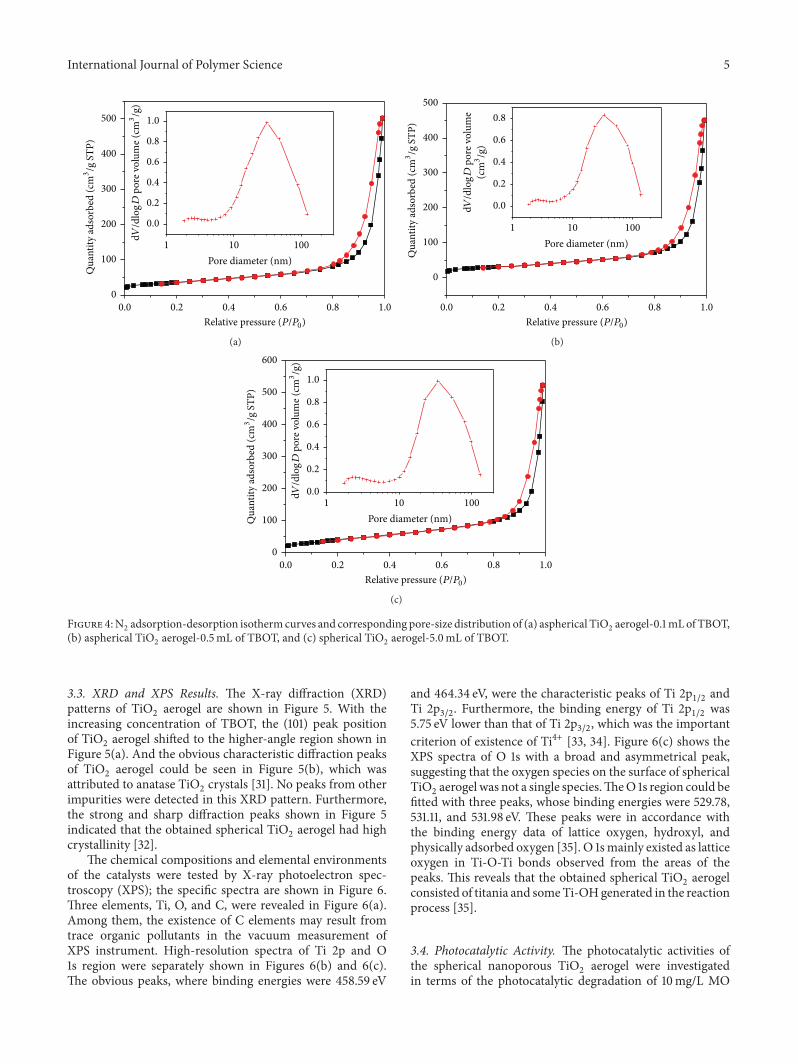
crystallinity [32].The chemical compositions and elemental environments
of the catalysts were tested by X-ray photoelectron spec-troscopy (XPS); the specific spectra are shown in Figure 6.Three elements, Ti, O, and C, were revealed in Figure 6(a).Among them, the existence of C elements may result fromtrace organic pollutants in the vacuum measurement ofXPS instrument. High-resolution spectra of Ti 2p and O1s region were separately shown in Figures 6(b) and 6(c).The obvious peaks, where binding energies were 458.59 eV
and 464.34 eV, were the characteristic peaks of Ti 2p1/2
andTi 2p3/2
. Furthermore, the binding energy of Ti 2p1/2
was5.75 eV lower than that of Ti 2p
3/2, which was the important
criterion of existence of Ti4+ [33, 34]. Figure 6(c) shows theXPS spectra of O 1s with a broad and asymmetrical peak,suggesting that the oxygen species on the surface of sphericalTiO2aerogel was not a single species.TheO 1s region could be
fitted with three peaks, whose binding energies were 529.78,531.11, and 531.98 eV. These peaks were in accordance withthe binding energy data of lattice oxygen, hydroxyl, andphysically adsorbed oxygen [35]. O 1smainly existed as latticeoxygen in Ti-O-Ti bonds observed from the areas of thepeaks. This reveals that the obtained spherical TiO
2aerogel
consisted of titania and someTi-OHgenerated in the reactionprocess [35].
3.4. Photocatalytic Activity. The photocatalytic activities ofthe spherical nanoporous TiO
2aerogel were investigated
in terms of the photocatalytic degradation of 10mg/L MO

6 International Journal of Polymer Science
Inte
nsity
(a.u
.)
24.5 25.0 25.5 26.0 26.524.02𝜃 (degree)
TiO2 aerogel-0.1mL TBOTTiO2 aerogel-0.5mL TBOTTiO2 aerogel-5.0mL TBOT
(a)
Inte
nsity
(a.u
.) (101
)
(004
)
(200
)
(105
)(211
)
(204
)
(116
)(220
)(215
)
20 30 40 50 60 70 80102𝜃 (degree)
TiO2 aerogel-0.1mL TBOTTiO2 aerogel-0.5mL TBOTTiO2 aerogel-5.0mL TBOT
(b)
Figure 5: XRD patterns of Ti diffraction peak at 2𝜃 = 25.26∘ (a) and TiO2aerogels calcinated at 500∘C for 3 h.
O (K
LL)
O 1
s
Ti 2
p
C 1s
Ti 3
s
Inte
nsity
(a.u
.)Ti
3p
Ti (L
MM
)
200 400 600 800 1000 1200 14000Binding energy (eV)
(a)
Inte
nsity
(a.u
.)
458.59
464.34
466 464 462 460 458 456468Binding energy (eV)
(b)
531.98
529.78
531.11
Inte
nsity
(a.u
.)
530 535525Binding energy (eV)
(c)
Figure 6: XPS spectra of TiO2aerogel (a) total spectrum; high-resolution spectrum of the (b) Ti 2p and (c) O 1s region.

International Journal of Polymer Science 7C
/C0
0.0
0.2
0.4
0.6
0.8
1.0
0 20 40 60 80 100−20Reaction time (min)
TiO2 aerogel-0.1mL TBOTTiO2 aerogel-0.5mL TBOTTiO2 aerogel-5.0mL TBOT
Figure 7: The degradation curves of MO in the presence of theTiO2aerogels prepared from 0.1mL of TBOT, 0.5mL of TBOT, and
0.5mL of TBOT.
under illumination of UV light within 90min (Figure 7).As a control, the activities of aspherical TiO
2aerogels were
also examined under the same conditions. Results of thephotocatalytic investigation are shown in Figure 7. Obviously,the photocatalytic activity of spherical TiO
2aerogel prepared
from 5.0mL of TBOT was higher than the aspherical TiO2
aerogels prepared from 0.1mL of TBOT and 0.5mL ofTBOT. In the process of adsorption equilibrium, the firstreaction time of 30min, the removal rate of MO with thespherical TiO
2aerogels was higher than that of aspherical
TiO2aerogels.This phenomenonmay result from the fact that
spherical TiO2aerogels had the higher specific surface area
than aspherical TiO2aerogels. Moreover, with the increase in
degradation time, the concentration ofMOdecreased rapidly,and, after 90min of irradiation, the decomposition ratio ofMO over the spherical TiO
2aerogels prepared from 5.0mL
of TBOT was about 92.9%, while those of aspherical TiO2
aerogels prepared from 0.1mL and 0.5mL of TBOT were87.8% and 88.8%.Therefore, both the spherical TiO
2aerogels
and the aspherical TiO2aerogels had excellent photocatalytic
activity of MO, which can be attributed to special anatasephase, specific surface areas, and unique structure [7].
4. Conclusions
Spherical TiO2aerogels were prepared by a simple ethanol-
thermal method, using spherical cellulose aerogel as the tem-plate and TBOT as raw material. The obtained TiO
2aerogels
consisted of TiO2nanoparticles with the diameter 15–20 nm.
The high specific surface area, ranging from 111.88m2/g to149.95m2/g, and good porosity of the network structuresprovided a large number of active sites for photocatalysis.ThehighestUV light activity, givingmethyl orange degradation of92.9%, was achieved by spherical TiO
2aerogel prepared from
5.0mL of TBOT under the calcination condition of 500∘C for3 h.
Competing Interests
The authors declare that there are no competing interestsregarding the publication of this paper.
Acknowledgments
This research was financially supported by the IndustryResearch Special Funds for Public Welfare Project underGrant no. 201504602, the Key Laboratory of Wood Sci-ence and Technology, Zhejiang Province, under Grant no.2014lygcz002, and the Fundamental Research Funds for theCentralUniversities underGrant no. 2572014EB01-02. Specialthanks are due to Professor Shujun Li for her equipment andanalysis.
References
[1] A. A. Ismail and D. W. Bahnemann, “Mesoporous titania pho-tocatalysts: preparation, characterization and reaction mecha-nisms,” Journal ofMaterials Chemistry, vol. 21, no. 32, pp. 11686–11707, 2011.
[2] R. Y. Zhang, A. A. Elzatahry, S. S. Al-Deyab, and D. Zhao,“Mesoporous titania: from synthesis to application,” NanoToday, vol. 7, no. 4, pp. 344–346, 2012.
[3] J. L. Vivero-Escoto, Y.-D. Chiang, K. C.-W. Wu, and Y.Yamauchi, “Recent progress in mesoporous titania materials:adjusting morphology for innovative applications,” Science andTechnology of Advanced Materials, vol. 13, no. 1, Article ID013003, 2012.
[4] L. P. Kumaresan, A. Prabhu, M. Palanichamy, E. Arumugam,and V. Murugesan, “Synthesis and characterization of Zr4+,La3+ and Ce3+ doped mesoporous TiO
2: evaluation of their
photocatalytic activity,” Journal of HazardousMaterials, vol. 186,no. 2-3, pp. 1183–1192, 2011.
[5] L. Kumaresan, A. Prabhu, M. Palanichamy, and V. Murugesan,“Synthesis of mesoporous TiO
2in aqueous alcoholic medium
and evaluation of its photocatalytic activity,” Materials Chem-istry and Physics, vol. 126, no. 1-2, pp. 445–452, 2011.
[6] P. Wang, J. Wang, X. F. Wang et al., “One-step synthesis ofeasy-recycling TiO
2-rGO nanocomposite photocatalysts with
enhanced photocatalytic activity,” Applied Catalysis B: Environ-mental, vol. 132-133, pp. 452–459, 2013.
[7] J. F. Ye, W. Liu, J. G. Cai et al., “Nanoporous anatase TiO2
mesocrystals: additive-free synthesis, remarkable crystalline-phase stability, and improved lithium insertion behavior,” Jour-nal of the American Chemical Society, vol. 133, no. 4, pp. 933–940, 2011.
[8] J. G. Yu, W. Liu, and H. G. Yu, “A one-pot approach to hier-archically nanoporous titania hollow microspheres with highphotocatalytic activity,” Crystal Growth and Design, vol. 8, no.3, pp. 930–934, 2008.
[9] Y. Liu, H. B. Jin, S. M. Zhu et al., “A facile method for fabricatingTiO2 @ mesoporous carbon and three-layered nanocompos-ites,” Nanotechnology, vol. 23, no. 32, Article ID 325602, 2012.
[10] B. Cheng, Y. Le, and J. Yu, “Preparation and enhancedphotocatalytic activity of Ag@TiO
2core-shell nanocomposite
nanowires,” Journal of Hazardous Materials, vol. 177, no. 1–3, pp.971–977, 2010.
[11] E. J. W. Crossland, N. Noel, V. Sivaram, T. Leijtens, J. A.Alexander-Webber, and H. J. Snaith, “Mesoporous TiO
2single

8 International Journal of Polymer Science
crystals delivering enhancedmobility and optoelectronic deviceperformance,” Nature, vol. 495, no. 7440, pp. 215–219, 2013.
[12] A. L. Linsebigler, G. Q. Lu, and J. T. Yates Jr., “Photocatalysison TiO
2surfaces: principles, mechanisms, and selected results,”
Chemical Reviews, vol. 95, no. 3, pp. 735–758, 1995.[13] R. Asahi, T. Morikawa, T. Ohwaki, K. Aoki, and Y. Taga,
“Visible-light photocatalysis in nitrogen-doped titaniumoxides,” Science, vol. 293, no. 5528, pp. 269–271, 2001.
[14] Z. Yanqing, S. Erwei, C. Zhizhan, L. Wenjun, and H. Xingfang,“Influence of solution concentration on the hydrothermalpreparation of titania crystallites,” Journal of Materials Chem-istry, vol. 11, no. 5, pp. 1547–1551, 2001.
[15] D. Eder and A. H. Windle, “Morphology control of CNT-TiO2
hybrid materials and rutile nanotubes,” Journal of MaterialsChemistry, vol. 18, no. 17, pp. 2036–2043, 2008.
[16] D. Eder, M. S. Motta, I. A. Kinloch, and A. H. Windle, “Anatasenanotubes as support for platinumnanocrystals,” Physica E, vol.37, no. 1-2, pp. 245–249, 2007.
[17] D. Eder, I. A. Kinloch, and A. H. Windle, “Pure rutile nan-otubes,”Chemical Communications, no. 13, pp. 1448–1450, 2006.
[18] D. Eder and A. H.Windle, “Carbon-inorganic hybridmaterials:the carbon-nanotube/TiO
2interface,” Advanced Materials, vol.
20, no. 9, pp. 1787–1793, 2008.[19] N. Bouazza, M. Ouzzine, M. A. Lillo-Rodenas, D. Eder, and
A. Linares-Solano, “TiO2nanotubes and CNT-TiO
2hybrid
materials for the photocatalytic oxidation of propene at lowconcentration,” Applied Catalysis B: Environmental, vol. 92, no.3-4, pp. 377–383, 2009.
[20] Y. S. Sohn, Y. R. Smith, M. Misra, and V. (Ravi) Subrama-nian, “Electrochemically assisted photocatalytic degradation ofmethyl orange using anodized titanium dioxide nanotubes,”Applied Catalysis B: Environmental, vol. 84, no. 3-4, pp. 372–378,2008.
[21] R. P. Antony, T. Mathews, A. Dasgupta, S. Dash, A. K. Tyagi,and B. Raj, “Rapid breakdown anodization technique for thesynthesis of high aspect ratio and high surface area anatase TiO
2
nanotube powders,” Journal of Solid State Chemistry, vol. 184,no. 3, pp. 624–632, 2011.
[22] A. Tighineanu, T. Ruff, S. Albu, R. Hahn, and P. Schmuki,“Conductivity of TiO
2nanotubes: influence of annealing time
and temperature,” Chemical Physics Letters, vol. 494, no. 4–6,pp. 260–263, 2010.
[23] B. D. Yao, Y. F. Chan, X. Y. Zhang, W. F. Zhang, Z. Y. Yang, andN. Wang, “Formation mechanism of TiO
2nanotubes,” Applied
Physics Letters, vol. 82, no. 2, pp. 281–283, 2003.[24] R. Yoshida, Y. Suzuki, and S. Yoshikawa, “Syntheses of TiO
2(B)
nanowires and TiO2anatase nanowires by hydrothermal and
post-heat treatments,” Journal of Solid State Chemistry, vol. 178,no. 7, pp. 2179–2185, 2005.
[25] G. Mogilevsky, Q. Chen, A. Kleinhammes, and Y. Wu, “Thestructure of multilayered titania nanotubes based on delami-nated anatase,” Chemical Physics Letters, vol. 460, no. 4–6, pp.517–520, 2008.
[26] S. Y. Chen, B. H. Zhou, W. L. Hu, W. Zhang, N. Yin, and H.Wang, “Polyol mediated synthesis of ZnO nanoparticles tem-plated by bacterial cellulose,”Carbohydrate Polymers, vol. 92, no.2, pp. 1953–1959, 2013.
[27] F. Liu, J. Lu, J. Shen, and Z. Zhang, “Preparation of mesoporousnickel oxide of sheet particles and its characterization,”Materi-als Chemistry and Physics, vol. 113, no. 1, pp. 18–20, 2009.
[28] M. Q. Chu and G. J. Liu, “Synthesis of liposomes-templatedCdSe hollow and solid nanospheres,”Materials Letters, vol. 60,no. 1, pp. 11–14, 2006.
[29] J. G. Yu, X. J. Zhao, and Q. N. Zhao, “Photocatalytic activityof nanometer TiO
2thin films prepared by the sol-gel method,”
Materials Chemistry andPhysics, vol. 69, no. 1–3, pp. 25–29, 2001.[30] Q. Zhang, W. Li, and S. X. Liu, “Controlled fabrication of
nanosized TiO2hollow sphere particles via acid catalytic
hydrolysis/hydrothermal treatment,” Powder Technology, vol.212, no. 1, pp. 145–150, 2011.
[31] D.-Y. Choi, J.-Y. Park, and J.-W. Lee, “Adsorption and photo-catalysis of spherical TiO
2particles prepared by hydrothermal
reaction,”Materials Letters, vol. 89, pp. 212–215, 2012.[32] G. G. Tang, D. Zhang, L. Zhao et al., “Template-free synthesis
of uniform TiO2mesoporous microspheres with enhanced
photocatalytic activity,” Materials Letters, vol. 118, pp. 192–195,2014.
[33] F. Mei, C. Liu, L. Zhang et al., “Microstructural study ofbinary TiO
2:SiO2nanocrystalline thin films,” Journal of Crystal
Growth, vol. 292, no. 1, pp. 87–91, 2006.[34] M. P. Casaletto,G.M. Ingo, S. Kaciulis, G.Mattogno, L. Pandolfi,
and G. Scavia, “Surface studies of in vitro biocompatibility oftitanium oxide coatings,” Applied Surface Science, vol. 172, no.1-2, pp. 167–177, 2001.
[35] G. Li, Z. Q. Liu, Z. Zhang, and X. Yan, “Preparation of titaniananotube arrays by the hydrothermal method,” Chinese Journalof Catalysis, vol. 30, no. 1, pp. 37–42, 2009.

Submit your manuscripts athttp://www.hindawi.com
ScientificaHindawi Publishing Corporationhttp://www.hindawi.com Volume 2014
CorrosionInternational Journal of
Hindawi Publishing Corporationhttp://www.hindawi.com Volume 2014
Polymer ScienceInternational Journal of
Hindawi Publishing Corporationhttp://www.hindawi.com Volume 2014
Hindawi Publishing Corporationhttp://www.hindawi.com Volume 2014
CeramicsJournal of
Hindawi Publishing Corporationhttp://www.hindawi.com Volume 2014
CompositesJournal of
NanoparticlesJournal of
Hindawi Publishing Corporationhttp://www.hindawi.com Volume 2014
Hindawi Publishing Corporationhttp://www.hindawi.com Volume 2014
International Journal of
Biomaterials
Hindawi Publishing Corporationhttp://www.hindawi.com Volume 2014
NanoscienceJournal of
TextilesHindawi Publishing Corporation http://www.hindawi.com Volume 2014
Journal of
NanotechnologyHindawi Publishing Corporationhttp://www.hindawi.com Volume 2014
Journal of
CrystallographyJournal of
Hindawi Publishing Corporationhttp://www.hindawi.com Volume 2014
The Scientific World JournalHindawi Publishing Corporation http://www.hindawi.com Volume 2014
Hindawi Publishing Corporationhttp://www.hindawi.com Volume 2014
CoatingsJournal of
Advances in
Materials Science and EngineeringHindawi Publishing Corporationhttp://www.hindawi.com Volume 2014
Smart Materials Research
Hindawi Publishing Corporationhttp://www.hindawi.com Volume 2014
Hindawi Publishing Corporationhttp://www.hindawi.com Volume 2014
MetallurgyJournal of
Hindawi Publishing Corporationhttp://www.hindawi.com Volume 2014
BioMed Research International
MaterialsJournal of
Hindawi Publishing Corporationhttp://www.hindawi.com Volume 2014
Nano
materials
Hindawi Publishing Corporationhttp://www.hindawi.com Volume 2014
Journal ofNanomaterials