Research Article Elastic-Plastic Numerical Analysis of...
13
Research Article Elastic-Plastic Numerical Analysis of Tunnel Stability Based on the Closest Point Projection Method Considering the Effect of Water Pressure Zhan-ping Song, 1 Ten-tian Yang, 1 and An-nan Jiang 2 1 School of Civil Engineering, Xi’an University of Architecture and Technology, Xi’an 710055, China 2 Transportation Equipment and Ocean Engineering College, Dalian Maritime University, Dalian 116026, China Correspondence should be addressed to Zhan-ping Song; [email protected] Received 6 August 2016; Accepted 6 September 2016 Academic Editor: Mitsuhiro Okayasu Copyright © 2016 Zhan-ping Song et al. is is an open access article distributed under the Creative Commons Attribution License, which permits unrestricted use, distribution, and reproduction in any medium, provided the original work is properly cited. To study the tunnel stability at various static water pressures and determine the mechanical properties and deformation behavior of surrounding rock, a modified effective stress formula was introduced into a numerical integration algorithm of elastic-plastic constitutive equation, that is, closest point projection method (CPPM). Taking the effects of water pressure and seepage into account, a CPPM-based formula was derived and a CPPM algorithm based on Drucker-Prager yield criterion considering the effect of pore water pressure was provided. On this basis, a CPPM-based elastic-plastic numerical analysis program considering pore water pressure was developed, which can be applied in the engineering of tunnels and other underground structures. e algorithm can accurately take the effects of groundwater on stability of surrounding rock mass into account and it can show the more pronounced effect of pore water pressure on stress, deformation, and the plastic zone in a tunnel. e stability of water flooding in Fusong tunnel was systematically analyzed using the developed program. e analysis results showed that the existence of groundwater seepage under tunnel construction will give rise to stress redistribution in the surrounding rock mass. Pore water pressure has a significant effect on the surrounding rock mass. 1. Introduction As a natural material, rock has numerous fractures, voids, and pores (i.e., fissures are rich in soluble rock), within which groundwater accumulates and is transported which affects deformation and failure of the rock. Groundwater is recognized as a dominant factor that influences the stability of rock engineering. In the construction of water-rich rock tunnels with a large buried depth, the surrounding rock mass is disturbed and damaged by construction, resulting in fre- quent accidents including flooding, mud slides, and leakage as a result of the coupling effects of high water pressure and high geostress. In the past, these misfortunes have resulted in serious economic damage and casualties [1–3]. Statistics con- cerning water-laden railway tunnels in China revealed that more than 80% of these tunnels either under construction or in operation had suffered various degrees of adversities including flooding and mudslides during construction and a full 30% of these tunnels are subject to groundwater pressure [4, 5]. As an additional consequence, these water-related mishaps induced by construction disturbance will also lead to a decline of groundwater levels with concomitant dry-up of springs and wells, leading to environmental deterioration including flow cutoff of rivers and brooks and withering of vegetation. is will directly affect local industrial and agricultural production as well as people’s lives. erefore, the study on stability of tunnels and other underground engineering under high water pressure is of great significance. e deformation and stress response of the rock mass surrounding a tunnel under high water pressure has been studied by many researchers in China and abroad. Using field testing, Bruno and Nakagawa [6] experimentally determined that water pore pressure had dual effects on crack growth and coalescence. Xing et al. [7] analyzed the influence of high Hindawi Publishing Corporation Mathematical Problems in Engineering Volume 2016, Article ID 2569345, 12 pages http://dx.doi.org/10.1155/2016/2569345
Transcript of Research Article Elastic-Plastic Numerical Analysis of...

Research ArticleElastic-Plastic Numerical Analysis of Tunnel StabilityBased on the Closest Point Projection Method Consideringthe Effect of Water Pressure
Zhan-ping Song1 Ten-tian Yang1 and An-nan Jiang2
1School of Civil Engineering Xirsquoan University of Architecture and Technology Xirsquoan 710055 China2Transportation Equipment and Ocean Engineering College Dalian Maritime University Dalian 116026 China
Correspondence should be addressed to Zhan-ping Song zhanpingsongsinacom
Received 6 August 2016 Accepted 6 September 2016
Academic Editor Mitsuhiro Okayasu
Copyright copy 2016 Zhan-ping Song et alThis is an open access article distributed under theCreativeCommonsAttribution Licensewhich permits unrestricted use distribution and reproduction in any medium provided the original work is properly cited
To study the tunnel stability at various static water pressures and determine the mechanical properties and deformation behaviorof surrounding rock a modified effective stress formula was introduced into a numerical integration algorithm of elastic-plasticconstitutive equation that is closest point projection method (CPPM) Taking the effects of water pressure and seepage intoaccount a CPPM-based formula was derived and a CPPM algorithm based on Drucker-Prager yield criterion considering theeffect of pore water pressure was provided On this basis a CPPM-based elastic-plastic numerical analysis program consideringpore water pressure was developed which can be applied in the engineering of tunnels and other underground structures Thealgorithm can accurately take the effects of groundwater on stability of surrounding rock mass into account and it can show themore pronounced effect of pore water pressure on stress deformation and the plastic zone in a tunnel The stability of waterflooding in Fusong tunnel was systematically analyzed using the developed programThe analysis results showed that the existenceof groundwater seepage under tunnel construction will give rise to stress redistribution in the surrounding rock mass Pore waterpressure has a significant effect on the surrounding rock mass
1 Introduction
As a natural material rock has numerous fractures voidsand pores (ie fissures are rich in soluble rock) withinwhich groundwater accumulates and is transported whichaffects deformation and failure of the rock Groundwater isrecognized as a dominant factor that influences the stabilityof rock engineering In the construction of water-rich rocktunnels with a large buried depth the surrounding rock massis disturbed and damaged by construction resulting in fre-quent accidents including flooding mud slides and leakageas a result of the coupling effects of high water pressure andhigh geostress In the past these misfortunes have resulted inserious economic damage and casualties [1ndash3] Statistics con-cerning water-laden railway tunnels in China revealed thatmore than 80 of these tunnels either under constructionor in operation had suffered various degrees of adversities
including flooding and mudslides during construction and afull 30 of these tunnels are subject to groundwater pressure[4 5] As an additional consequence these water-relatedmishaps induced by construction disturbance will also leadto a decline of groundwater levels with concomitant dry-upof springs and wells leading to environmental deteriorationincluding flow cutoff of rivers and brooks and witheringof vegetation This will directly affect local industrial andagricultural production as well as peoplersquos lives Thereforethe study on stability of tunnels and other undergroundengineering under highwater pressure is of great significance
The deformation and stress response of the rock masssurrounding a tunnel under high water pressure has beenstudied bymany researchers in China and abroad Using fieldtesting Bruno and Nakagawa [6] experimentally determinedthat water pore pressure had dual effects on crack growthand coalescence Xing et al [7] analyzed the influence of high
Hindawi Publishing CorporationMathematical Problems in EngineeringVolume 2016 Article ID 2569345 12 pageshttpdxdoiorg10115520162569345
2 Mathematical Problems in Engineering
confining pressure and high water pressure on deformabilitystrength and the ductile-to-brittle transition of brittle rockusing complete stress-strain triaxial compression tests Xuet al [8] conducted triaxial compression tests to study theeffects of water pore pressure on the mechanical proper-ties of sandstone under water-filling conditions Bao et al[9] studied the effect of high water pressure on the rockdeformation and rock acoustic emission using experimentand numerical analysis She and Cui [10] conducted rockcreep tests under high pore pressure Using analytical andnumerical calculations Li et al [11] deduced an elastic-plasticanalytical solution for a deep tunnel in a water seepagefield Based on effective stress principles and pore pressurein each element Wang [12] and Wang et al [13] simulatedthe deformation caused by constant pore pressure acting onrock and the localization process under various confiningpressures and pore pressures using FLAC software Fanget al [14] reviewed analytical solutions for water pressuredistribution under steady seepage in a tunnel and compriseda fluid-solid coupling simulation These research results arevaluable reference for the study of the instability mechanismof water flooding in deep tunnels of water-rich zone and thedevelopment of preventionmeasures However there are stillno theoretical system and comprehensive conclusions due tothe complexity of this problem Therefore further study anddiscussion are necessary
In this paper a modified effective stress formula wasintroduced into the CPPM and the integration algorithmfor elastic-plastic constitutive equation Then elastic-plasticnumerical analysis program was developed considering theeffect of water pore pressure in tunnels and other under-ground engineering structures The stability of the tunnelunder various water pressure conditions was analyzed basedon the developed programThe variation laws of stress strainand plastic zone were also studied This developed programis also used in the analysis of true engineering named Fusongtunnel of China
2 Elastic-Plastic Numerical ProgramConsidering Surrounding Rock MassSubject to Water Pore Pressure
21 Closest Point Projection Method with Water Pore PressureThe closest point projectionmethod is a plastic finite elementmethod algorithm which consists of two parts the initialelastic trial step and the plastic corrector stepThey are drivenby the total strain increment andplastic parameter incrementrespectively The plastic strain and the internal variables arekept fixed in the elastic trial step The total strain remainsunchanged in the plastic corrector step [15 16]
Pore pressure distribution designated from the possiblemechanical deformation is sufficient for solving the problemof static groundwater The constant pore pressure is estab-lished by considering the action of pore pressure for the stresscalculation by solving the effective stress of all nodes Waterpore pressure is constant throughout the whole calculationprocess and the pore pressure affects the rock primarilythrough effective stress The pore pressure distribution is
O
② ①
120583
120591
120590
Figure 1 Mohrrsquos circle moves under the action of pore waterpressure
consistent with the initial condition and not the influence ofmechanical deformation Some scholars proposed improvedeffective stress formula according to rockmass as follows [17]
1205901015840 = 120590 minus 120572119901119908 (0 le 120572 le 1) (1)
where 1205901015840 is effective stress tensor 1205901015840 is the total stress tensorand 120572 is equivalent pore pressure coefficient it is decided byrock pore and crack growth degree 119901119908 is pore water pressureand 120572119901119908 is equivalent pore pressure
The effect of water pressure on the strength of thematerialis represented by Mohrrsquos circle The stress condition is shownin Figure 1(A) before the introduction of water pore pressure119906 = 0 All the normal components of the stress tensorare effectively reduced through the pore pressure after theintroduction of pore pressure 119906 = 0 as shown in Figure 1(B)Mohrrsquos circle moves towards the left under the action of thewaterrsquos pore pressure and to the destruction of the material
The closest point projection method for the Drucker-Prager criteria the updated stress at the 119899+1 step is as follows
120590119899+1 = 120590trial119899+1 minus Δ120574119863119890119873119899+1 (2)
where minusΔ120574119863119890119873119899+1 is the return vector 120590trial119899+1 is trial stressΔ120574 is the plastic multiplier and 119873119899+1 is the flow vectorThere are two possible forms of the returnmapping algorithmaccording to the flow vector at the smooth cone or at the apex
Returning to the smooth cone the accumulated strain120576119901119899+1 is120576119901119899+1 = 120576119901119899 + Δ120576119901 = 120576119901119899 + 120585Δ120574 (3)
where 120576119901119899 is the accumulate strain at the 119899 step Δ120576119901 is theincrement of accumulate strain and 120585 is the constant relevantto the friction angle
The consistency condition is
Φ119899+1 = radic1198692 (s119899+1) + 120578119901119899+1 minus 120585119888 (Δ120576119901119899+1) = 0 (4)
where 119904119899+1 is the deviator stress tensor 119901119899+1 is hydrostaticpressure 120578 is a constant related to the friction angle and119888(120576119901119899+1) is hardened modulus
Mathematical Problems in Engineering 3
p
Complementarycone
UpdatedDrucker-
Prager
120590trialn+1
ptrialn+1
minusKΔ120576p I
120590n+1 = pn+1I
radicJ2(s)
criteria
Figure 2 The trial stress return to the apex singularity
Solving formula (4) the calculatedΔ120574 updated stress120590119899+1at the 119899 + 1 step is
120590119899+1 = 120590trial119899+1 minus Δ120574( 119866radic1198692 (119904trial119899+1) 119904trial119899+1 +1198701205783 119868) (5)
Returning to the apex singularity as shown in Figure 2stress is only relevant with a body strain increment Δ120576119901V andan accumulated plastic strain 120576119901119899+1
120576119901119899+1 = 120576119901119899 + Δ120576119901 = 120576119901119899 + 120585120578Δ120576119901V (6)
The consistency condition is
Φ119899+1 = 119888(120576119901119899 + 120585120578Δ120576119901V) 120585120578 minus 119901trial119899+1 + 119870Δ120576119901V = 0 (7)
Solving (7) we obtain the updated stress 120590119899+1120590119899+1 = 119901trial
119899+1 minus 119870Δ120576119901V (8)
The above calculation assumes the return to the apexsingularity but actually also solves 119904119899+1 to judge whether toreturn to the smooth cone or the apex singularity as shownin Figure 3
radic1198692 (119904119899+1) = radic1198692 (119904trial119899+1) minus 119866Δ120574 ge 0 (9)
Stress returning to the cone of the yield surface is effectiveOtherwise it returns to the apex of the yield surface
The total stress 120590 of (1) at the closest point projectionmethod of the Drucker-Prager criteria can be obtainedfrom the calculation formula of the closest point projectionmethod considering the action of pore water pressure thenwe can calculate the effective stress 1205901015840
Assuming the water is incompressible nonsteady seepagecontinuity equation is as follows according to Darcyrsquos law
120597120597119909 (119896119909 120597ℎ120597119909) + 120597120597119910 (119896119910 120597ℎ120597119910) + 120597120597119911 (119896119911 120597ℎ120597119911) = 119878119904 120597ℎ120597119905 (10)
where ℎ is permeability head 119909 119910 and 119911 are the spatialcoordinates 119905 is the time coordinate 119896119909 119896119910 and 119896119911 are the
I
Apex p
Updatedelastic domain
120590trialn+1
120590trialn+1
120578
120590n+1
120590n+1
radicJ2(s)
radicJ2(Strialn+1 ) minus G Δ120574 gt 0
radicJ2(Strialn+1 ) minus G Δ120574 lt 0
120585c(120576pn+1)
Figure 3 The judgment of the trial stress return to location
permeability coefficients whose directions are parallel to the119909-119910- and 119911-axis respectively and 119878119904 is the water storage rateThe initial condition of unconfined nonsteady seepage
definite condition with free surface is as followsℎ|119905=0 = ℎ0 (119909 119910 119911 0) (11)
Head boundary and flow boundary are as followsℎ|1198721
= 1198911 (119909 119910 119911 119905) 119896119899 120597ℎ120597119899 10038161003816100381610038161003816100381610038161003816119872
2
= 1198912 (119909 119910 119911 119905) (12)
where1198721 is the known head boundary 1198911 is the known headboundary value 1198722 is the known flow boundary and 1198912 isthe known flow boundary value
22 Self-Development of the Program of Elastic-Plastic FEMSelf-development of the elastic-plastic program of Drucker-Prager criteria under the action of pore water pressureis based on the original elastic finite element programThe program was developed with an object-oriented C++language through the debug in the Visual 60 environmentDealing with grid division by ANSYS software and stressdisplacement and other values are graphically displayed bythe Tecplot software Completion of the whole process of thesolution is accomplished using the finite element programwhich can analyze special engineering problems consideringthe effect of water pressure based on the CPPM under theDrucker-Prager constitutive model as shown in Figure 4
Making use of an incremental-iterative method in thenonlinear finite element a piecewise linear solution isobtained that approximates the nonlinear solution The totalload 119891 is divided into a number of load increments Δ119891 Theresulting finite element incremental equation is119870(Δ119889119894) Δ119889119894 = Δ119891 (13)
Solving (13) using theNewton-Raphson iteration schemethe process is as follows
(1) Initialize the displacement 1198890 stress 1205900 and strain 1205760respectively
(2) At load step 119899 + 1 (119899 + 1 = 1 2 3 119873 step) havethe load increment Δ119891119899+1ext to solve 119891119899+1ext
4 Mathematical Problems in Engineering
Computer internal forces
No
Yes
Compute tangential stiffness matrix
Computation of the closest point
Elastic update
No
Yes
Check validity of return tothe cone of surface
No
Update other state variables and exit
Yes
Initialization d0 = 0 1205900 = 0 1205760 = 0
n + 1 = 1 2 3 middot middot middot N
i = 1 2 3 middot middot middotM
fn+1intt = int ΩBT 120590n+1
idΩ
Test fn+1ext minus fn+1
inti lt TOL
Kn+1Ti = int ΩBT Dn+1BdΩ
Solve Kn+1Ti Δd = Δf = fn+1
ext minus fn+1inti
projection method 120590n+1i+1
Compute 120590trialn+1i
Check consistency 120593(120590trialn+1i )
120590n+1i = 120590trialn+1
iSolve Y 120590n+1
120590n+1Return the apex solve 120576
p
force fn+1ext = int ΩNb n+1dΩ+ int ΓN n+1dΓ
Compute external
Figure 4 The finite element program of the closest point projection method
(3) At the 119894 iteration of load step 119899+1 where 119894 = 1 2 3 maxiter have 119891119899+1int1 = 119891119899+1ext to solve internal forces119891119899+1int1
(4) Use the formula 119891119899+1ext minus 119891119899+1int119894 lt tolerance forconvergence test if there is convergence then returnto step (2) to the next load step calculation otherwiseproceed to step (5)
(5) Calculate the tangent stiffness matrix119870119899+1119879119894 by solvingthe elastic stiffness matrix 119863119890 in the initial elasticstage using the consistent tangent stiffness matrix inthe plastic stage solving the elastoplastic constitutivematrix119863119890119901
(6) Solve the constitutive equation (13) and obtain thedisplacement increment Δ119889119894
(7) For each step 119889119899+11 = 119889119899 Δ119889119899+1acc = 0 119889119899+1119894+1 =119889119899+1119894 + Δ119889119894 and Δ119889119899+1acc119894+1 = Δ119889119899+1acc119894 + Δ119889119894 the strainincrement is Δ120576119894
(8) TheCPPMof theDrucker-Prager criteria is presentedto solve the effective stress 120590119899+1119894+1 solving the elastic-plastic factor Δ120574119894+1 Using the Newton-Raphson iter-ative scheme can obtain approximate square conver-gence speed once again as follows
A At the time 119905119899 calculate the strain incrementΔ120576119894 and the internal variable 120576119899119901119894 and obtain the
predicted hydrostatic pressure 119901119899+1trial119894+1 and par-tial stress tensor 119904119899+1trial119894+1 in the elastic predictedstate
B Judge in the plastic state if Φ119899+1trial119894+1 le 0 thenobtain the stress 120590119899+1119894+1 at the time 119905119899+1 Exit intothe next load step calculation or the plasticcorrector step
C Assuming a return to the cone of yield surfaceset the initial value Δ1205740 = 0
D Make use of the Newton-Raphson iterationscheme to solve Δ120574119894+1 and judge whether thereis convergence if |120601119899+1119894+1 le tol| obtain theupdated stress 120590119899+1119894+1 otherwise continue to theNewton-Raphson iteration
E Judge whether to return to the location of thetrial stress the above assumes a return to thecone of yield surface if radic1198692(119904119899+1119894+1 ) ge 0 predictif the stress needed to return to the cone of theyield surface is effective Otherwise predict thestress needed to return to the apex singularity
F Set the initial value Δ120576119901V = 0 solve Δ120576119901V using theNewton-Raphson iteration scheme and judgewhether there is convergence If |119903| le tol getthe updated stress 120590119899+1119894+1 otherwise continue toNewton-Raphson iteration
Mathematical Problems in Engineering 5
10m
q
x
Y
10m
1m
Figure 5 FEMmodel of circular tunnel
(9) Calculate the stress after at the 119894+1 iteration step turnto step (3) and continue to iteration
23 Validation of Program and Numerical Simulation Inorder to verify the reliability of the program a plane-strainFEM model of a circular tunnel was established [18] Asshown in Figure 5 the model contains 613 elements and671 nodes with a size of 10m times 10m The simulated tunnelwith a radius of 1m is subject to a uniformly distributedload 119902 at the upper surface of the model The elastic-plasticDrucker-Prager model is applied in the simulation It isassumed that rockmass is homogeneous and fractures are notdeveloped The density of the rock mass is 120588 = 2650 kgm3and the distributed load 119902 = minus2500KNm2 In additionthe simulation requires the specification of Youngrsquos modulus119864 Poissonrsquos ratio 120583 cohesion 119888 a friction angle 120601 and anangle of dilatation 120593 All calculations were based on valuesof 119864 = 2GPa 120583 = 03 119888 = 082MPa 120593 = 30∘ and 120601 = 30∘The equivalent coefficient of the pore water pressure 120572 wasset to be 10
When there is no pore water pressure the uniformly dis-tributed load is applied incrementally and the load incrementwill be applied over 5 stepsThe load increment is 500KNm2for each step Calculated values of displacement using theprogram are compared with the values obtained fromANSYSsoftware under the same condition As shown in Figure 6 thedisplacement values at some nodes around the tunnel area aregiven
According to displacement comparison at all nodes themaximum relative error is 89 in 119883-direction and 203 in119884-direction between the values obtained from the programand ANSYS The conformity shown in these plotted datareflects the reliability of the program
3 Mechanical Characteristics andPlastic Zone of the Circular Tunnelwith Pore Water Pressure
31 Project Profile Fusong tunnel is located in Jingyu countyBaishan city in the east of Jilin province of China Thetunnel consists of two bores with centers separated by 13sim35m The left bore has a total length of 1625m with itsstarting and ending chainage of ZK275+170 and ZK276+795respectively The right bore has a total length of 1600mwith its starting and ending chainage of RK275+180 andRK276+780 The maximum excavation width of the tunnelis about 12m The tunnel height is 76m The area wheretunnel is located belongs to the Changbai mountains foothillsarea which is an overlying Quaternary loose formationOutcropped strata in the area consist primarily of Jurassiclake-river facies clasolite andesite and Tertiary-Quaternarybasalt In addition Archaeozoic andUpper Proterozoic strataare sporadically distributed Groundwater in the tunnel areamainly consists of pore phreatic water in a loose accumula-tion layer and fissure water in bedrock which is rechargedfrom precipitation and discharged into a gully The area hasa continental climate with a dry and severely cold winterand a hot summer There is a relatively abundant rainfallfrom June to August with an average annual precipitation of9394mmThere is a fault 1198651 near RK275+390 at the entranceof Fusong tunnel where a seasonal river runs over this sectionof the tunnel Obviously the influence of the riverwater needsto be considered with respect to the tunnel stability duringthe rainy season Therefore a section in right tunnel fromRK275+173 to RK275+390 with a total length of 204m wasselected for study
32 Seepage Analysis of the Tunnel
321 Seepage Analysis Model and Analysis Process For thestudy of the tunnel construction stability at the entrancetaking seepage into consideration a practical rule of thumbis that the variation of stress and displacement induced byunloading in the circular tunnel which is excavated in ahomogeneous elastic infinite domain is less than 1 overa radius being 5 times tunnel radius and 5 over a radiusbeing 3 times tunnel radiusTherefore in accordancewith thespecific requirements of the project discretization error andcomputational error in the FEM the calculation scale was atleast a radius being 3-4 times tunnel radius in each directionThenumericalmodel had dimensions of 204mtimes 70mtimes 90m(lengthtimeswidthtimesheight) and full-face excavationwas appliedin the numerical simulation (Figure 7)
In order to consider the effect of seepage on strengthof the tunnelrsquos surrounding rocks physical and mechanicalparameters of the geomaterials in FEM model includingpermeability and the saturated unit weight of soils werespecified as shown in Table 1 The boundary conditions ofseepage in the FEMmodel are shown in Figure 8
The hydraulic head of the nodes in the vertical directionvaried from 52 to 69m and the surrounding rock mass belowthe hydraulic head was considered to be saturated beforeexcavation It was also assumed that the geologic model was
6 Mathematical Problems in Engineering
Table 1 Physical and mechanical parameters of geomaterials
LithotypeYoungrsquosmodulus119864GPa
Poissonrsquosratio119906 Unit weight
(KNm3)
Saturatedunit weight(KNm3)
Cohesion119888KPa Friction angle120601∘ Permeabilitycoefficient
mdGravel soil amp rubble 04 045 16 173 100 17 1 times 10minus1Calcareous mudstone 09 03 22 235 300 30 1 times 10minus3Calcareous siltstone 08 035 20 216 200 25 1 times 10minus3
Step 1
Step 2
Step 3
Step 4
Step 5
Step I
Step II
Step III
Step IV
Step V
106
113
116
112
111
115
108
110
107
109
102
104
103
114
101
105
Node number
minus40E minus 04
minus30E minus 04
minus20E minus 04
minus10E minus 04
00E + 00
10E minus 04
20E minus 04
30E minus 04
40E minus 04
X-d
ispla
cem
ents
(a) Displacement comparison in119883-direction
103
104
105
102
114
115
116
110
111
112
113
106
107
108
109
Node
Step 1
Step 2
Step 3
Step 4
Step 5
Step I
Step II
Step III
Step IV
Step V
minus90E minus 03
minus80E minus 03
minus70E minus 03
minus60E minus 03
minus50E minus 03
minus40E minus 03
minus30E minus 03
minus20E minus 03
minus10E minus 03
00E + 00
Y-d
ispla
cem
ents
(b) Displacement comparison in 119884-direction
Figure 6 Comparison of displacements in 119883- and 119884-direction
X
Z
Y
Figure 7 Longitudinal section of right bore of Fusong tunnel
impermeable at anterior rear and bottom surfaces Afterexcavation was completed the boundary condition of thelinings considered to be drained was applied The process
of analysis considering the tunnel construction proceduressubject to seepage was composed of the following steps
(1) Initial seepage field analysis(2) Initial stress field analysis based on step (1)(3) Tunnel excavation which was assumed to be made in
one step under seepage and stress fields(4) Seepage field changes of surrounding rock mass after
tunnel excavation
322 Analysis of Seepage Characteristics in the Tunnel Theseepage characteristics in the tunnel at lowerwater levels wereanalyzed Analysis of seepage characteristics in the tunnelshows that before excavation the pore pressure at the bottomagrees with total hydraulic head value and pore pressureincreases from top to bottom Figure 9 is the seepage velocityof tunnel section ZK275+290
It is shown that groundwatermaintains a balance existingin the form of a hydrostatic pressure After excavation theseepage field changed (linings were set to be drained)
Mathematical Problems in Engineering 7
Study object
Alti
tude
(m)
Horizontal scale 1 2000
Vertical scale 1 1000
470480490500510520530540550560570580590600
(the y
ello
w se
a alti
tude
syste
m)
S67∘e
Figure 8 Seepage boundary conditions of FEMmodel
the pore pressure decreased dramatically and the seepagevelocity increased rapidly around the tunnel Meanwhilenew permeable boundary was generated around the tunneland pore pressure was zero The seepage velocity vectorsin the 119883119884119885-direction were also analyzed which meansgroundwater seeps into the tunnel along radial directionand the seepage flow along tunnel axis is weak due to asmall hydraulic gradient The seepage velocity of water insurrounding rockmass at ZK275+290 section is not generallylarge with maximum value of up to 11 times 10minus4ms
33 Comparison Analysis of Tunnel Stability Subject to SeepageorNo Seepage Themost commonly used tunnel surroundingrock safety indexes are as follows (1) limit displacementof surrounding rock (2) the scope of damage zone ofsurrounding rock (3) safety factor of surrounding rock Weanalyzed the displacements stress and damage zone (plasticzone) of surrounding rock considering and not consideringseepage based on the numerical simulation
331 Influence of Seepage on Displacement of SurroundingRock Mass As shown in Figure 10 displacements of the sur-rounding rock mass at the ZK275+290 section are presentedwhich consider coupling or no coupling of seepage andstress Coupling analysis of seepage and stress was consideredduring the tunnel construction as shown in Figures 10(a)and 10(c) while only rock self-weight was considered inFigures 10(b) and 10(d) Nephograms in Figures 10(b) and10(d) indicate that displacements at both the tunnel roof andbottom are greater after excavation horizontal and verticaldisplacements are distributed symmetrically about the centerof the tunnel and the vertical displacement at the vault andbottom increased with a decrease in the buried depth ofthe calculated nodes The horizontal displacement exhibitedthe same characteristics at either side of the arch waistwith a displacement value of approximately 17mm Themaximum value of the horizontal displacement appearedat the arch waist Therefore a one-step tunnel excavationhas an influence on the surrounding rock mass mainly in
the form of a vertical deformation Comparing between thecalculation displacements and warning value the stabilitydegree of surrounding rock could be obtained The limitdisplacement of surrounding rock of the section is decidedby experience analogies and standard as 25mm
Nephograms shown in Figures 10(a) and 10(c) indicatethat the maximum displacement of the surrounding rockmass appeared on tunnel floor and heaving displacementat the inverted arch was as much as 227mm while thesettlement displacement was up to 122mmThe surroundingrock displacementsmeet safety requirementTheheaving dis-placement was about 183 times the value that occurred whenno seepage was considered Comparison between Figures10(a) and 10(b) shows that the following seepage increased thehorizontal displacement of both sides of the archwaist 7 timeswhen compared with no seepage These findings show thatthe seepage has an adverse impact on stability of the tunnelTherefore strengthening of the support measures to preventcollapse of tunnel needs to be considered
332 Influence of Seepage on the Stress of the Surrounding RockMass As shown in Figure 11 the maximum and minimumprincipal stresses are developed depending on whether thereis seepage or no seepage Comparison of the nephogramsshown in Figure 11 indicates that the seepage significantlycontributed to an increase of the maximum principal stressand it also was found that the maximum principal stressbelow the tunnel floor is apparently greater than that atthe tunnel roof when seepage is considered However themaximum principal stress in the surrounding rock mass wasuniformly distributed All these findings show that seepagestress redistribution in surrounding rock mass was inducedby seepage and the influence was more significant on tunnelfloor than on tunnel roof Furthermore it alsowas found thatin the case of no seepage the local tensile stress appearedbelow tunnel floor due to seepage while there was onlycompressive stress in the surrounding rock mass
Developed shear stresses are shown in Figures 11(d) and11(e) When there was no seepage it is found that shear stressappeared along the arch waist of the tunnel and at both endsof the inverted arch of the tunnel The maximum shear stresswith X-shaped distribution appeared at the left arch footDue to influence of seepage the distribution range of shearstress was wider and the value of the shear stress was largerTherefore seepage will cause redistribution and an increaseof shear stress in the surrounding rock mass
333 Influence of Seepage on the Equivalent Plastic Zone in theSurrounding Tunnel Rock Mass The plastic zone producedduring the tunnel excavation can be represented by anequivalent plastic strain which can be used to illustrate theextent of surrounding rock damage Figure 12 depicts theequivalent plastic strain of the surrounding rock mass aftercompletion of tunnel excavation
As can be seen the plastic zone with seepage is largerand more widely distributed than the plastic zone withoutseepage and even extends to the region below the tunnelWhen seepage was not considered the plastic zone occurredonly at the arch footTherefore it is important to detect water
8 Mathematical Problems in Engineering
minus917775e minus 005
minus764840e minus 005
minus611906e minus 005
minus458971e minus 005
minus306036e minus 005
minus153101e minus 005
minus166796e minus 008
+152768e minus 005
+305703e minus 005
+458637e minus 005
+611572e minus 005
+764507e minus 005
+917441e minus 005
(a) 119883-directionminus165358e minus 005
minus148615e minus 005
minus131872e minus 005
minus115128e minus 005
minus983852e minus 005
minus816419e minus 006
minus648986e minus 006
minus481554e minus 006
minus314121e minus 006
minus146688e minus 006
+207444e minus 007
+188177e minus 006
+355610e minus 006
(b) 119884-direction
minus110600e minus 004
minus963667e minus 005
minus821333e minus 005
minus678998e minus 005
minus536663e minus 005
minus394328e minus 005
minus251994e minus 005
minus109659e minus 005
+326756e minus 005
+175010e minus 005
+317345e minus 005
+459680e minus 005
+602014e minus 005
(c) 119885-direction+403739e minus 006
+129305e minus 005
+218235e minus 005
+307166e minus 005
+396097e minus 005
+485027e minus 005
+573958e minus 005
+662889e minus 005
+751819e minus 005
+840750e minus 005
+929681e minus 005
+101861e minus 004
+110754e minus 004
(d) 119883119884119885-direction
Figure 9 Nephograms of seepage velocity of surrounding rock mass at tunnel section ZK275+290 (ms)
minus140874e minus 002minus120336e minus 002minus997981e minus 003minus792602e minus 003minus587224e minus 003minus381845e minus 003minus176466e minus 003+289124e minus 004+234291e minus 003+439670e minus 003+645049e minus 003+850427e minus 003+105581e minus 002+126118e minus 002
(a) 119883-direction displacement considering seepageminus190844e minus 003
minus160134e minus 003
minus129424e minus 003
minus987137e minus 004
minus680036e minus 004
minus372935e minus 004
minus658336e minus 005
+241268e minus 004
+548369e minus 004
+855470e minus 004
+116257e minus 003
+146967e minus 003
+177677e minus 003
(b) 119883-direction displacement without considering seepage
minus122882e minus 002
minus959461e minus 003
minus690102e minus 003
minus420744e minus 003
minus151386e minus 003
+117973e minus 003
+387331e minus 003
+656690e minus 003
+926048e minus 003
+119541e minus 002
+146476e minus 002
+173412e minus 002
+200348e minus 002
+227284e minus 002
(c) 119885-direction displacement considering seepageminus109834e minus 002
minus903455e minus 003
minus708568e minus 003
minus519681e minus 003
minus318794e minus 003
minus123907e minus 003
+709794e minus 004
+265866e minus 002
+460753e minus 003
+655640e minus 003
+850527e minus 003
+104541e minus 002
+124030e minus 002
(d) 119885-direction displacement without considering seepage
Figure 10 Nephograms of displacement at ZK275+290 section surrounding rockmass considering seepage and without considering seepage(m)
Mathematical Problems in Engineering 9
minus524784e + 002minus458974e minus 002minus393163e + 002minus327353e + 002minus261542e + 002minus195732e + 002minus129924e + 002minus641104e + 001+170017e + 000+675107e + 001+133321e + 002+199132e + 002+264942e + 002+330753e + 002
(a) Maximum principal stress considering seepageminus906594e + 002
minus816471e + 002
minus726348e + 002
minus636224e + 002
minus546101e + 002
minus455978e + 002
minus365855e + 002
minus275732e + 002
minus185609e + 002
minus954855e + 001
minus536230e + 000
+847609e + 001
+174884e + 002
(b) Maximum principal stress considering no seepage
minus708606e + 002
minus608551e + 002
minus508496e + 002
minus408440e + 002
minus308385e + 002
minus208330e + 002
minus108275e + 002
minus821947e + 000
+918358e + 001
+191891e + 002
+291946e + 002
+392002e + 002
+492057e + 002
(c) Minimum principal stress considering seepageminus119396e + 003
minus109801e + 003
minus100205e + 003
minus906100e + 002
minus810147e + 002
minus714195e + 002
minus618242e + 002
minus522289e + 002
minus426336e + 002
minus330384e minus 002
minus234431e minus 002
minus138478e + 002
minus425254e + 001
(d) Minimum principal stress considering no seepage
minus306964e + 002
minus229665e + 002
minus152365e + 002
minus750657e + 001
+223376e + 000
+795333e + 001
+156833e + 002
+234132e + 002
+311432e + 002
+388731e + 002
+466031e + 002
+543330e + 002
+620630e + 002
(e) Shear stress considering seepageminus276163e + 002
minus207672e + 002
minus139182e + 002
minus706909e + 001
minus22002e + 000
+662904e + 001
+134781e + 002
+203272e + 002
+271762e + 002
+340253e + 002
+408744e + 002
+477234e + 002
+545725e + 002
(f) Shear stress considering no seepage
Figure 11 Nephograms of stress of surrounding rock mass at ZK275+290 section considering seepage and no seepage
+000000e + 000
+623959e minus 004
+124792e minus 003
+187188e minus 003
+249584e minus 003
+311980e minus 003
+374376e minus 003
+436771e minus 003
+499167e minus 003
+561563e minus 003
+623959e minus 003
+686355e minus 003
+748751e minus 003
(a) Equivalent plastic zone under seepage+000000e + 000
+189797e minus 005
+379595e minus 005
+569392e minus 005
+759189e minus 005
+948987e minus 005
+113878e minus 004
+132858e minus 004
+151838e minus 004
+170818e minus 004
+189797e minus 004
+208777e minus 004
+227757e minus 004
(b) Equivalent plastic zone under no seepage
Figure 12 Nephograms of equivalent plastic zone at ZK275+290 section considering seepage and no seepage (KPa)
10 Mathematical Problems in Engineering
+000000e + 000
+417857e minus 004
+835713e minus 004
+125357e minus 003
+167143e minus 003
+208928e minus 003
+250714e minus 003
+292500e minus 003
+334285e minus 003
+376071e minus 003
+417857e minus 003
+459642e minus 003
+501428e minus 003
(a) Pore water pressure is 0MPa+000000e + 000
+520369e minus 003
+104074e minus 003
+156111e minus 003
+208148e minus 003
+260185e minus 003
+312221e minus 003
+364258e minus 003
+416295e minus 003
+468322e minus 003
+520369e minus 003
+572406e minus 003
+624443e minus 003
(b) Pore water pressure is 01MPa+000000e + 000
+101073e minus 003
+202146e minus 003
+303220e minus 003
+404293e minus 003
+505366e minus 003
+606439e minus 003
+707513e minus 003
+808586e minus 003
+909659e minus 003
+101073e minus 002
+111181e minus 002
+121288e minus 002
(c) Pore water pressure is 025MPa
+000000e + 000
+115655e minus 003
+231310e minus 003
+346964e minus 003
+462619e minus 003
+578274e minus 003
+693929e minus 003
+809583e minus 003
+925238e minus 003
+104089e minus 002
+115655e minus 002
+127220e minus 002
+138786e minus 002
(d) Pore water pressure is 03MPa+000000e + 000
+136005e minus 003
+272110e minus 003
+408164e minus 003
+544219e minus 003
+680274e minus 003
+816392e minus 003
+952384e minus 003
+108844e minus 002
+122449e minus 002
+136055e minus 002
+149660e minus 002
+163266e minus 002
(e) Pore water pressure is 05MPa+000000e + 000
+186524e minus 003
+373048e minus 003
+559572e minus 003
+746096e minus 003
+932620e minus 003
+111914e minus 002
+130567e minus 002
+149219e minus 002
+167872e minus 002
+186524e minus 002
+205177e minus 002
+223829e minus 002
(f) Pore water pressure is 06MPa
Figure 13 The change process of the plastic zone with the different pore water pressure
in advance during construction and antiseepage measuresneed to be promptly applied in order to prevent a wide rangeof the plastic zone Particular attention should be paid to thesupport at the arch foot
34 Analysis of Tunnel Stability Considering Seepage at Var-ious Hydraulic Heads There was a discordant contact zonebetween calcareous mudstone and calcareous siltstone at theZK275+290 chainage section in the Fusong tunnel Overthis contact zone there was a seasonal river that has ahydraulic connection with the water in the contact zoneThus the stability of tunnelrsquos surrounding rock mass andpotential water flooding through the heading face can occurduring seasonal flash floods The scope of surrounding rockdamage zone can reflect the safety of surrounding rockThe larger the damage zone the more dangerous the sur-rounding rock Consequently the distribution characteristicsof the plastic zone under seepage pressures of 0 01MPa025MPa 03MPa 05MPa and 06MPa were analyzedbased on the assumption that the rock mass in the plasticzone was homogenous with perfect elastic-plastic behaviorSimulations based on these assumptions showed that therewill be a rapid increase in the displacement of geomaterialsand penetration of the plastic zone in heading face when thegeomaterials undergo plastic yield This scenario will causemajor mishaps such as major flooding mudslides and apotential failure of the tunnel structure Figure 13 shows the
plastic zones in surrounding rock mass and heading face ofthe tunnel at various different seepage pressures
As shown in Figure 13(a) the distribution of the plasticzone when the seepage pressure is zero indicates that the areaof plastic zone is small in the excavated area under just theweight of the earth and is mainly concentrated at arch waistand arch springing The tensile stress appears at the bottomof heading face but it is distributed in a small range in themiddle of the heading face As has been noted the area ofthe plastic zone at the heading face accounts for about 25of the total area of the heading face With an increase inseepage pressure the area of plastic zone gradually increasesand the plastic zone at the side wall of the excavated sectionextends towards the heading face Under these conditionsthe depth and range of the plastic zone in the heading facealso increased and the range of tensile stress at the bottomof the heading face continued to expand When the seepagepressure increased to 025MPa the range of the tensile stressin the heading face increased by 50 and rock mass in theheading face deformed plastically over a small depth in theplastic zone In addition there was no penetration betweenthe plastic zones in excavated section and the heading faceBut when seepage pressure increased to 03MPa the plasticzone in excavated section penetrated into the heading faceWhen the seepage pressure increased to 05MPa the plasticzone in excavated section completely penetrated into theheading face Consequently the region of the tensile stressappeared below the heading face which accounted for more
Mathematical Problems in Engineering 11
than 30 of the total area of the heading face At this timewater flooding may occur through the heading face whichwill result in an integral-sliding failure if the seepage pressureis any greater
4 Conclusions
In light of the frequent disasters including flooding mud-slides and general leakage that can result from high waterpressure during construction of tunnels and other under-ground structures in water-rich regions a mathematicalalgorithmwas adopted to model the problemThis algorithmconsisted of a modified effective stress formula that wasintroduced into the CPPM together with an adopted integra-tion algorithm of an elastic-plastic constitutive equation andelastic-plastic finite element program which can adopt waterpore pressure The resulting study showed that pore waterpressure has a significant influence on stress deformationand the plastic zone of a rock mass that surrounds a tunnelWith an increase of pore pressure changes in the plastic zoneof the surrounding rock mass are more pronounced
The developed program was used to study the effect ofseepage pressure on stress deformation and the plastic zoneof surrounding rock mass of the tunnel which goes througha discordant contact zone at the tunnel entrance Some ofconclusions of this study were as follows
(1) Pore water pressure has a significant influence onstress deformation and the plastic zone of thesurrounding rock mass of Fusong tunnel With anincrease of pore pressure the areas of the plastic zoneon tunnel heading face and completed section of thetunnel increased Therefore the influence of ground-water on tunnel stability needs to be considered whenthe tunnel is located at high water levels and passesthrough a permeable discordant contact zone
(2) Existence of groundwater flow during tunnel con-struction results in stress redistribution in the sur-rounding rock mass When considering the influenceof the seepage the settlement displacement at thetunnel top and heaving displacement at the bottomcaused by tunnel excavation will increase It was alsofound that the horizontal and vertical displacementsof the surrounding rock mass are distributed sym-metrically about the center of the tunnel Vertical dis-placement at the tunnel vault and bottom increasedwith a decrease in buried depth of the calculatednodes
(3) Comparison between displacements under circum-stances of seepage and no seepage indicates thattensile stress appeared in the surrounding rock massat the bottom of the tunnel due to seepage which isdetrimental to the stability of the tunnel Thereforetunnel sections in areas with high hydraulic headseepage require extra measures to enhance supportand prevent collapse of the tunnel in the design phase
(4) Stability analysis of the tunnel during constructionconsidering different groundwater levels reveals that
during the construction of the tunnel crossing a faultin rainy season potential water flooding at headingface must be considered if there is a connectionbetween water in discordant contact zone and surfacewater So it is suggested to adopt full-face curtaingrouting to ensure the safety of the heading face
Competing Interests
The authors declare that there is no conflict of interestsregarding the publication of this paper
Acknowledgments
The authors deeply appreciate support from the NationalNatural Science Foundation (51678101 and 51578447)
References
[1] Z M Xu and R Q Huang Deep Buried Long Tunnel andthe Construction of Geological Hazards Southwest Jiao TongUniversity Press Chengdu China 2000
[2] Z W Liu Mechanism of Water Inrush in Karst Tunnel andCountermeasures of Prevention and Control China Universityof Geosciences Beijing China 2004
[3] F L He and Y C Zhang Geological Hazards of Tunnel andIts Forecast Southwest Jiao Tong University Press ChengduChina 2011
[4] WH Shi ldquoTheprevention and control of water gushing disasterof railway tunnelrdquoTheChinese Journal of Geological Hazard andControl vol 4 no 1 pp 46ndash55 1993
[5] Z P Song Study on the Concealed Cave Influence of TunnelSurrounding Rock and Supporting Structure Xirsquoan University ofTechnology Xirsquoan China 2006
[6] M S Bruno and F M Nakagawa ldquoPore pressure influence ontensile fracture propagation in sedimentary rockrdquo InternationalJournal of RockMechanics andMining Sciences amp GeomechanicsAbstracts vol 28 no 4 pp 261ndash273 1991
[7] F D Xing Z D Zhu H L Liu et al ldquoCompressive strengthexperimental study on deformation characteristics of brittlerock under high confining pressure and hydraulic pressurerdquoJournal of Hehai University (Natural Sciences) vol 02 pp 184ndash187 2004
[8] J Xu H W Yang S C Li et al ldquoExperimental study ofeffects of cyclic loading and unloading pore water pressureon deformation characteristic of sandstonerdquo Chinese Journal ofRock Mechanics and Engineering vol 28 no 05 pp 892ndash8992009
[9] C Y Bao A N Jiang C A Tang et al ldquoStudy of acoustic emis-sion characteristics of limestone under cycle uniaxial loading-unloading perturbationrdquoChinese Journal of RockMechanics andEngineering vol 30 no S2 pp 3871ndash3877 2011
[10] X C She and X Cui ldquoInfluence of high pore water pressure oncreep properties of rockrdquoChinese Journal of RockMechanics andEngineering vol 29 no 8 pp 1603ndash1609 2010
[11] Z L Li Q W Ren and Y H Wang ldquoElasto-plastic analyticalsolution of deep-buried circle tunnel considering fluid flowfieldrdquo Chinese Journal of Rock Mechanics and Engineering vol23 no 8 pp 1291ndash1295 2004
12 Mathematical Problems in Engineering
[12] X B Wang ldquoEffect of pore pressure on entire deformationalcharacteristics of rock specimenrdquo Journal of Shen Yang Jian ZhuUniversity (Nature Science) vol 21 no 6 pp 621ndash628 2005
[13] X B Wang W Wang and Y S Pan ldquoNumerical simulationof the strain localization of the surrounding rock of a circulartunnel at different pore pressurerdquo Journal of China Coal Societyvol 35 no 5 pp 723ndash728 2010
[14] Q Fang D L Zhang and M Q Huang ldquoAnalysis of seepageproblem induced by subsea tunnel excavation based on contin-uum medium modelrdquo Chinese Journal of Rock Mechanics andEngineering vol 26 no 2 pp 3776ndash3784 2007
[15] T BelytschkoWK Liu andBMoranNonlinear Finite Elementfor Continua and Structures JohnWiley amp Sons New York NYUSA 2000
[16] E A de Souza Neto D Perirsquoc and D R J OwenComputationalMethods for PlasticityTheory and Applications Markono Singa-pore 2008
[17] M A Biot ldquoGeneral theory of three-dimensional consolida-tionrdquo Journal of Applied Physics vol 12 no 2 pp 155ndash164 1941
[18] J X Wang and A N Jiang ldquoElastoplastic CPPM algorithm andmechanical parameters inversion of tunnel surrounding rockunder the action of pore water pressurerdquo Journal of Basic Scienceand Engineering vol 22 no 3 pp 525ndash538 2014
Submit your manuscripts athttpwwwhindawicom
Hindawi Publishing Corporationhttpwwwhindawicom Volume 2014
MathematicsJournal of
Hindawi Publishing Corporationhttpwwwhindawicom Volume 2014
Mathematical Problems in Engineering
Hindawi Publishing Corporationhttpwwwhindawicom
Differential EquationsInternational Journal of
Volume 2014
Applied MathematicsJournal of
Hindawi Publishing Corporationhttpwwwhindawicom Volume 2014
Probability and StatisticsHindawi Publishing Corporationhttpwwwhindawicom Volume 2014
Journal of
Hindawi Publishing Corporationhttpwwwhindawicom Volume 2014
Mathematical PhysicsAdvances in
Complex AnalysisJournal of
Hindawi Publishing Corporationhttpwwwhindawicom Volume 2014
OptimizationJournal of
Hindawi Publishing Corporationhttpwwwhindawicom Volume 2014
CombinatoricsHindawi Publishing Corporationhttpwwwhindawicom Volume 2014
International Journal of
Hindawi Publishing Corporationhttpwwwhindawicom Volume 2014
Operations ResearchAdvances in
Journal of
Hindawi Publishing Corporationhttpwwwhindawicom Volume 2014
Function Spaces
Abstract and Applied AnalysisHindawi Publishing Corporationhttpwwwhindawicom Volume 2014
International Journal of Mathematics and Mathematical Sciences
Hindawi Publishing Corporationhttpwwwhindawicom Volume 2014
The Scientific World JournalHindawi Publishing Corporation httpwwwhindawicom Volume 2014
Hindawi Publishing Corporationhttpwwwhindawicom Volume 2014
Algebra
Discrete Dynamics in Nature and Society
Hindawi Publishing Corporationhttpwwwhindawicom Volume 2014
Hindawi Publishing Corporationhttpwwwhindawicom Volume 2014
Decision SciencesAdvances in
Discrete MathematicsJournal of
Hindawi Publishing Corporationhttpwwwhindawicom
Volume 2014 Hindawi Publishing Corporationhttpwwwhindawicom Volume 2014
Stochastic AnalysisInternational Journal of
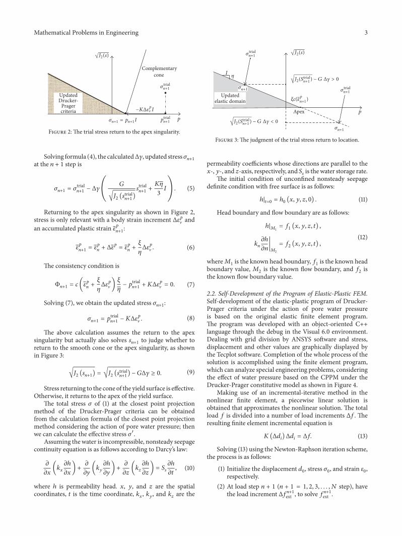
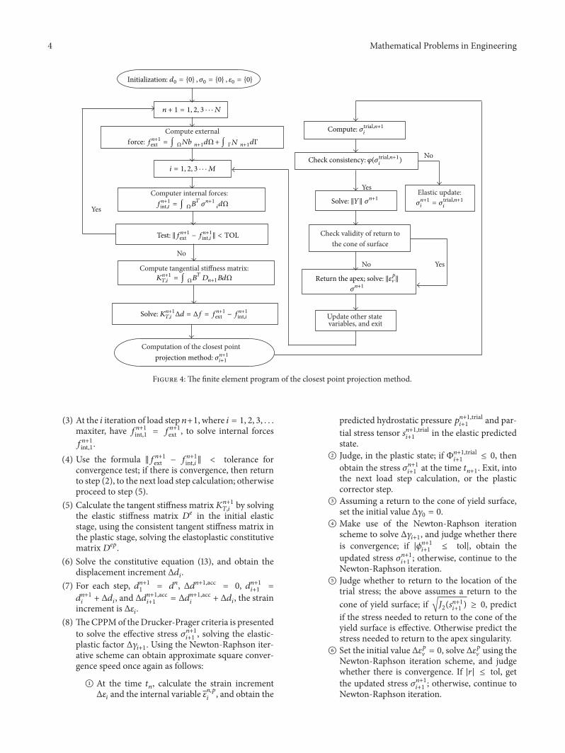
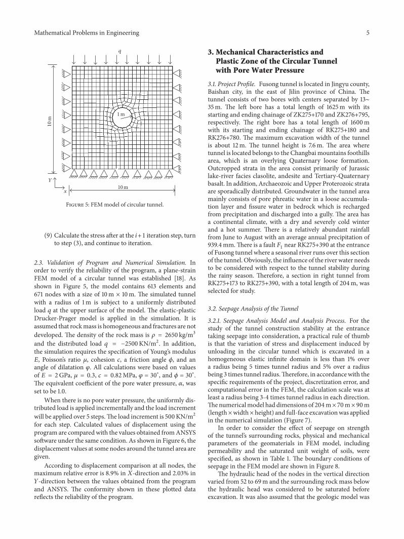
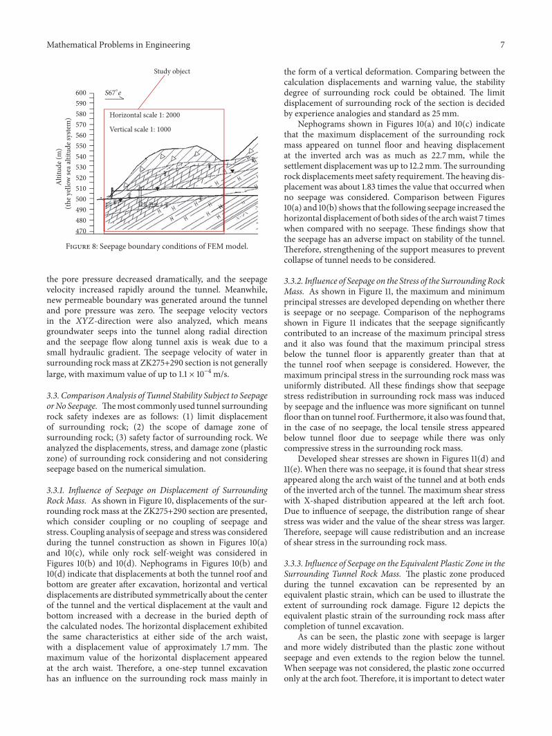
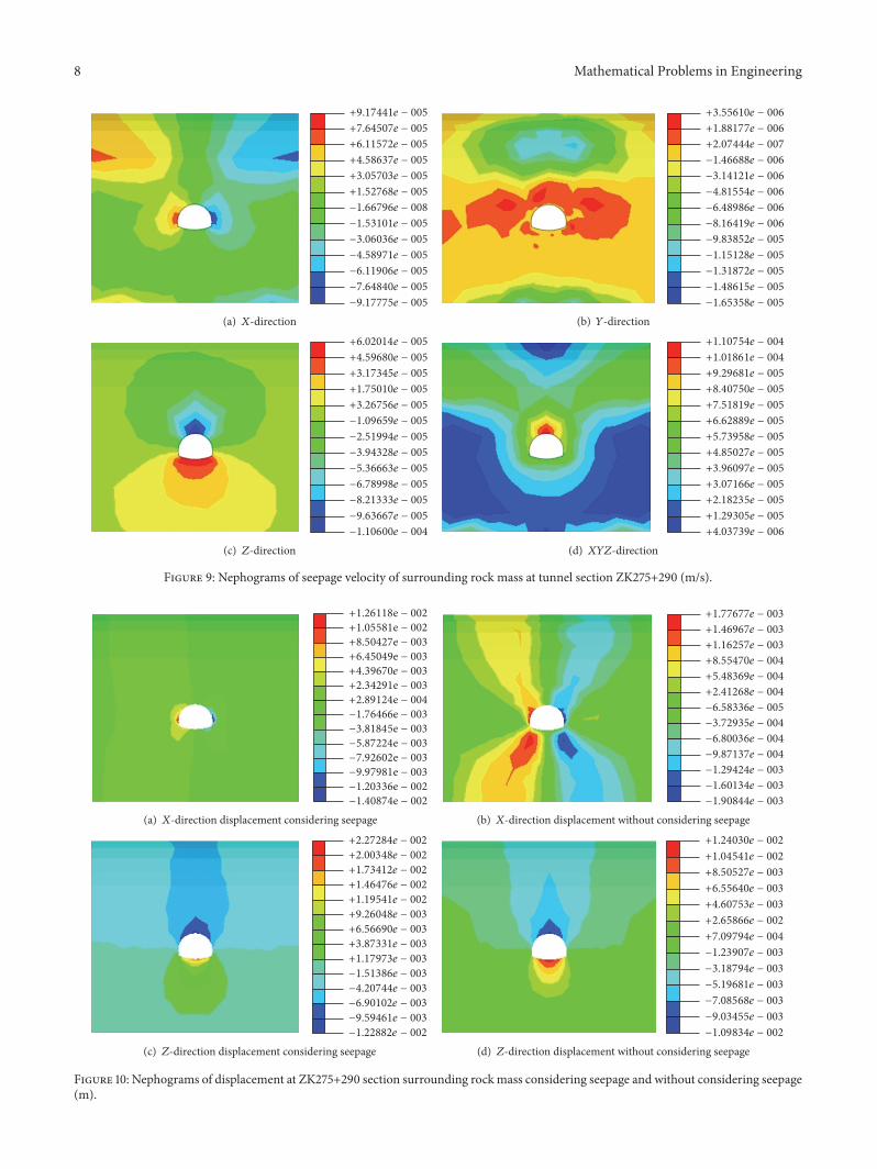
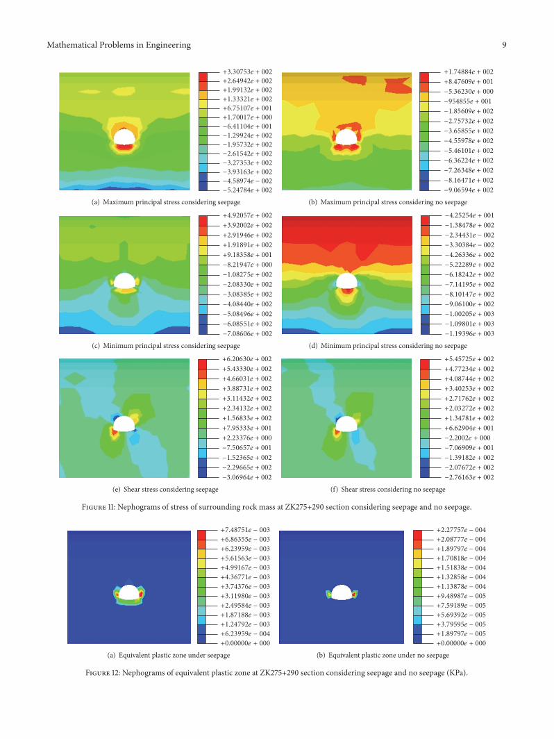
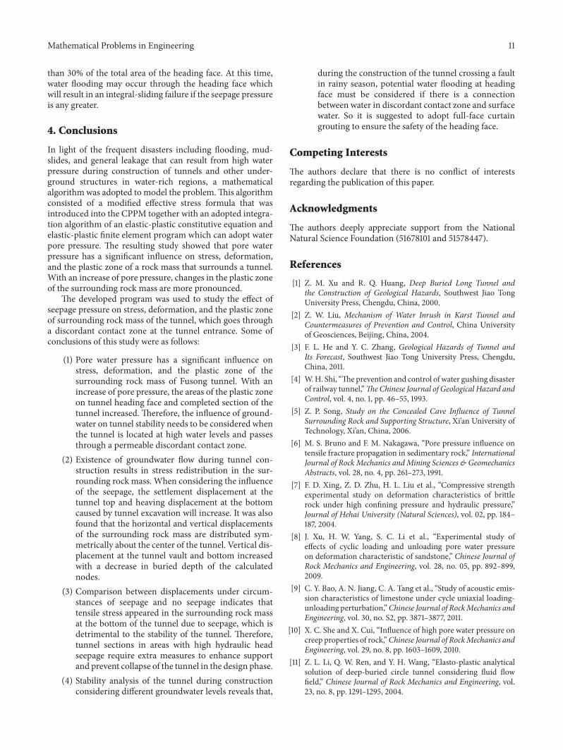