Research Article Dynamic Stability Improvement of Grid ...
15
Research Article Dynamic Stability Improvement of Grid Connected DFIG Using Enhanced Field Oriented Control Technique for High Voltage Ride Through V. N. Ananth Duggirala 1 and V. Nagesh Kumar Gundavarapu 2 1 Department of EEE, Viswanadha Institute of Technology and Management, Visakhapatnam 531173, India 2 Department of EEE, GITAM University, Visakhapatnam, Andhra Pradesh 530045, India Correspondence should be addressed to V. Nagesh Kumar Gundavarapu; [email protected] Received 25 June 2015; Accepted 29 September 2015 Academic Editor: Shuhui Li Copyright © 2015 V. N. A. Duggirala and V. N. K. Gundavarapu. is is an open access article distributed under the Creative Commons Attribution License, which permits unrestricted use, distribution, and reproduction in any medium, provided the original work is properly cited. Doubly fed induction generator (DFIG) is a better alternative to increased power demand. Modern grid regulations force DFIG to operate without losing synchronism during overvoltages called high voltage ride through (HVRT) during grid faults. Enhanced field oriented control technique (EFOC) was proposed in Rotor Side Control of DFIG converter to improve power flow transfer and to improve dynamic and transient stability. Further electromagnetic oscillations are damped, improved voltage mitigation and limit surge currents for sustained operation of DFIG during voltage swells. e proposed strategy has advantages such as improved reactive power control, better damping of electromagnetic torque oscillations, and improved continuity of voltage and current from stator and rotor to grid during disturbance. In EFOC technique, rotor flux reference changes its value from synchronous speed to zero during fault for injecting current at the rotor slip frequency. In this process, DC-Offset component of stator flux is controlled so that decomposition during overvoltage faults can be minimized. e offset decomposition of flux will be oscillatory in a conventional FOC, whereas in EFOC it is aimed to be quick damping. e system performance with overvoltage of 1.3 times, 1.62 times, and 2 times the rated voltage occurring is analyzed by using simulation studies. 1. Introduction e doubly fed induction generator (DFIG) is preferred due to its small size with higher MVA ratings available in the market, low power ratings of converters, variable genera- tor speed and constant frequency operation, robust four- quadrant reactive power control, and improved performance during the high and low voltage ride through (HVRT and LVRT). However, DFIG is sensitive to external disturbances like voltage swell and sag. If grid voltage falls or rises suddenly due to any reason, large surge currents enter the rotor terminals and induce the voltage significantly. So, the rotor side converter (RSC) gets damaged due to exceeding voltage or the current rating. Apart from this, there will be huge electromagnetic torque pulsations and increase in rotor speed which may reduce burden on gears of the wind turbine- generator. Such phenomenon reduces lifetime of overall system. A study of LVRT and HVRT issue for DFIG with rotor current dynamics is given in [1]. In this paper, rotor open and short circuit analysis and differential equations are derived and analyzed to improve the capability of DFIG during disturbances. Hybrid current controllers are used to improve the capability of DFIG to deliver desired reactive power and withstand capability during LVRT and HVRT in [2]. In [3], authors discuss the problems and possible measures to improve performance during HVRT by proposing active voltage control. A fast coordinated control scheme based on the characteristics of DFIG was proposed to improve perfor- mance during LVRT and HVRT [4]. Effects of asymmetrical HVRT are analyzed and control strategy for improving performance during overvoltages is done in [5]. A grid side converter (GSC) based control strategy to improve voltage changes in DC link capacitor during HVRT is shown in [6]. FACTS devices like STATCOM [7] and dynamic voltage Hindawi Publishing Corporation Journal of Renewable Energy Volume 2015, Article ID 490178, 14 pages http://dx.doi.org/10.1155/2015/490178
Transcript of Research Article Dynamic Stability Improvement of Grid ...

Research ArticleDynamic Stability Improvement of Grid Connected DFIGUsing Enhanced Field Oriented Control Technique for HighVoltage Ride Through
V N Ananth Duggirala1 and V Nagesh Kumar Gundavarapu2
1Department of EEE Viswanadha Institute of Technology and Management Visakhapatnam 531173 India2Department of EEE GITAM University Visakhapatnam Andhra Pradesh 530045 India
Correspondence should be addressed to V Nagesh Kumar Gundavarapu drgvnk14gmailcom
Received 25 June 2015 Accepted 29 September 2015
Academic Editor Shuhui Li
Copyright copy 2015 V N A Duggirala and V N K Gundavarapu This is an open access article distributed under the CreativeCommons Attribution License which permits unrestricted use distribution and reproduction in any medium provided theoriginal work is properly cited
Doubly fed induction generator (DFIG) is a better alternative to increased power demand Modern grid regulations force DFIGto operate without losing synchronism during overvoltages called high voltage ride through (HVRT) during grid faults Enhancedfield oriented control technique (EFOC) was proposed in Rotor Side Control of DFIG converter to improve power flow transferand to improve dynamic and transient stability Further electromagnetic oscillations are damped improved voltage mitigation andlimit surge currents for sustained operation of DFIG during voltage swellsThe proposed strategy has advantages such as improvedreactive power control better damping of electromagnetic torque oscillations and improved continuity of voltage and currentfrom stator and rotor to grid during disturbance In EFOC technique rotor flux reference changes its value from synchronousspeed to zero during fault for injecting current at the rotor slip frequency In this process DC-Offset component of stator flux iscontrolled so that decomposition during overvoltage faults can be minimized The offset decomposition of flux will be oscillatoryin a conventional FOC whereas in EFOC it is aimed to be quick damping The system performance with overvoltage of 13 times162 times and 2 times the rated voltage occurring is analyzed by using simulation studies
1 Introduction
The doubly fed induction generator (DFIG) is preferred dueto its small size with higher MVA ratings available in themarket low power ratings of converters variable genera-tor speed and constant frequency operation robust four-quadrant reactive power control and improved performanceduring the high and low voltage ride through (HVRT andLVRT) However DFIG is sensitive to external disturbanceslike voltage swell and sag If grid voltage falls or rises suddenlydue to any reason large surge currents enter the rotorterminals and induce the voltage significantly So the rotorside converter (RSC) gets damaged due to exceeding voltageor the current rating Apart from this there will be hugeelectromagnetic torque pulsations and increase in rotor speedwhich may reduce burden on gears of the wind turbine-generator Such phenomenon reduces lifetime of overallsystem
A study of LVRT and HVRT issue for DFIG with rotorcurrent dynamics is given in [1] In this paper rotor open andshort circuit analysis and differential equations are derivedand analyzed to improve the capability of DFIG duringdisturbances Hybrid current controllers are used to improvethe capability of DFIG to deliver desired reactive powerand withstand capability during LVRT and HVRT in [2]In [3] authors discuss the problems and possible measuresto improve performance during HVRT by proposing activevoltage control A fast coordinated control scheme based onthe characteristics of DFIG was proposed to improve perfor-mance during LVRT and HVRT [4] Effects of asymmetricalHVRT are analyzed and control strategy for improvingperformance during overvoltages is done in [5] A grid sideconverter (GSC) based control strategy to improve voltagechanges in DC link capacitor during HVRT is shown in[6] FACTS devices like STATCOM [7] and dynamic voltage
Hindawi Publishing CorporationJournal of Renewable EnergyVolume 2015 Article ID 490178 14 pageshttpdxdoiorg1011552015490178
2 Journal of Renewable Energy
restorer [8] are used to mitigate voltage swell without phaseangle deviation and to investigate HVRT issues Energystorage devices like SMES to meet the requirement of trans-mission system operators (TSOs) for wind generation systemof HVRT through two grid codes have been discussed in [9]The critical comparison between HVRT and LVRT is drawnin [10] The use of active resistance to suppress rotor currentand torque oscillations for enhanced operation HVRT isdescribed in [11]
Some external passive elements and active sources areused in conjunction to improve stability and thereby leadingto a better LVRT operation of DFIG during symmetrical andasymmetrical faults Single phase crowbar supercapacitorenergy storage system [12] fault current limiter (FCL) [13]and superconducting FCL with magnetic energy storagedevices [14] are connected in coordination with DFIG systemto enhance system LVRT behavior during severe faults
The STATCOM [15ndash22] familiar shunt device fromFACTS family is used to surmount the system to losesynchronism due to external disturbances like large sym-metrical and asymmetrical faults voltage rise variation inwind speed and subsynchronous resonance Two sequencecomponents with dual voltage control during grid faults forDFIG-STATCOM system are used in [22 23] The DVRwith high temperature superconductor fault current limiter(SCFCL) application is used for controlling balanced andunbalanced grid faults for DFIG [24] Eigenanalysis withfrequency domain approach used for sea-shore wind farm toimprove system stability for DFIG and SCIG is discussed in[25] by applying an UPFC controller The process of energystorage with the help of superconducting coil by integratingit to the DC link back-to-back converters for DFIG system isdiscussed in [26]
The research on the behavior of DFIG system duringHVRT is still in its nascence There are a few research papersavailable As per modern grid codes for the countries likeAustralia and Spain DFIG system must withstand to 13times the rated voltage without losing synchronism It isgenerally observed that with sudden increase in grid voltagestator and rotor voltages increase and current decreases Theelectromagnetic torque (EMT) increases when rotor speeddecreases The rotor voltage and current frequency decreaseas slip frequency decreases (sf) due to decrease in slip valueThe rotor current decrease for DFIG depends on rotor andstator winding parameters increase in voltage magnitude atgrid and decrease in speed of rotor If rotor and stator fluxchange is controlled EMT rotor speed andmachine currentscan be controlled effectively To achieve this the first stepis that a new reference synchronous speed has to be chosenbased on change in speed during faultThe second step is thatDC offset component of flux must be eliminated oscillationsmust be damped and change in magnitude of 119902-axis fluxcomponents must be controlledThis methodology is termedas enhanced field oriented control (EFOC) The efficacy ofEFOC is analyzed for a standard DFIG system for improvingvoltage and current profile of stator and rotor with stabletorque speed and flux control mechanism
The system performance with overvoltage at grid ter-minals during 08 to 12 seconds with an electromagnetic
torque of 200Nm is analyzed In the analysis the grid faultvoltage is considered in three cases case 1 13 times case 2162 times and case 3 2 times the grid voltage with otherparameters remaining constant The voltage and currentparameters at rotor stator grid voltage and DFIG electro-magnetic torque (EMT) and speed of the rotor are comparedand analyzed for all the three cases The proposed EFOCmethod can be applicable to both LVRT and HVRT issueswhich help in improving current and voltage profile at statorand rotor terminals during disturbance Better performanceDFIG operation is expected when using EFOC techniquein contrast to the conventional FOC method In additionthere is no need to use robust PIR or any other sophisticatedcontrollers Generally when a severe grid overvoltage occursoscillations arise with the increase of stator terminal voltageDC link capacitor voltage increases speed of rotor decreasesand electromagnetic torque increases
In Section 2 design of converters for EFOC is explainedIn Section 3 mathematical modeling of wind turbine andgenerator converters for the grid connected DFIG isexplained during transient state In this section effect of sys-tem during symmetrical fault EFOC control technique andbehavior ofmechanical and electrical systemwith variation inrotor speed are explained in subsections Simulation resultsare described in Section 4 of overvoltage of 13 162 and 2times the rated voltage in the MATLAB environment Theconclusion is presented in Section 5 followedby theAppendixand References
2 Design of Rotor Side ConverterControl for EFOC
RSC controller helps in improving reactive power demand atgrid and in extracting maximum power from the machineby making the rotor run at optimal speed The optimalspeed of the rotor is decided from machinersquos real powerand rotor speed characteristic curves fromMPPT algorithmThe stator active and reactive power control is possible withthe RSC controller strategy through 119894119902119903 and 119894119889119903 componentscontrolling respectively The rotor voltage in a stationaryreference frame [11] and further analysis from [27] is givenby
119881119904
119903= 119881119904
0119903+ 119877119903119894119904
119903+ 120590119871119903
119889119894119904
119903
119889119905minus 119895120596119894119904
119903 (1a)
where 120590 = 1 minus 1198712
119898119871 119904119871119903 120596 is the rotor speed 119894119904
119903is the rotor
current in a stationary frame of reference 119871 119904 119871119903 and 119871119898 arestator the rotor and mutual inductance parameters in Henryor in pu and
119881119904
0119903=119871119898
119871 119904
(119889
119889119905minus 119895120596119904)Φ119904
119904(1b)
is the voltage induced in the stator flux with
Φ119904
119904= 119871 119904119894119904
119904+ 119871119898119894
119904
119904
Φ119904
119903= 119871119903119894119904
119903+ 119871119898119894
119904
119903
(2)
Journal of Renewable Energy 3
The 119889- and 119902-axis rotor voltage equations ((1a) (1b)) and(2) in the synchronous rotating reference frame are given by
119881119889119903 =119889Φ119889119903
119889119905minus (120596119904 minus 120596)Φ119902119903 + 119877119903119894119889119903
119881119902119903 =119889Φ119902119903
119889119905+ (120596119904 minus 120596)Φ119889119903 + 119877119903119894119902119903
(3)
The stator and rotor two-axis fluxes are
Φ119889119903 = (119871 119897119903 + 119871119898) 119894119889119903 + 119871119898119894119889119904
Φ119902119903 = (119871 119897119903 + 119871119898) 119894119902119903 + 119871119898119894119902119904
Φ119889119904 = (119871 119897119904 + 119871119898) 119894119889119904 + 119871119898119894119889119903
Φ119902119904 = (119871 119897119904 + 119871119898) 119894119902119904 + 119871119898119894119902119903
(4)
where 119871119903 = 119871119897119903+ 119871119898 119871 119904 = 119871
119897119904+ 119871119898 and 120596119903 = 120596
119904minus 120596
By substituting (4) into (3) and by rearranging the termsthen
119881119889119903 = (119877119903 +1198891198711015840
119903
119889119905) 119894119889119903 minus 119904120596119904119871
1015840
119903119894119902119903+119871119898
119871 119904
119881119889119904
119881119902119903 = (119877119903 +1198891198711015840
119903
119889119905) 119894119902119903 + 119904120596119904119871
1015840
119903119894119889119903
+119871119898
119871 119904
(119881119902119904 minus 120596Φ119889119904)
(5)
where 120596 is rotor speed 120596Φ119904 is speed of stator flux and 120596119904 issynchronous speed
The MATLAB and SIMULINK based on the controlcircuit of RSC for enhancing performance for LVRT issues arepresented in Figure 1 The right side corner with subsystem 2is a subcircuit of the controller for EFOC technique and itsdesign is shown later in Figure 5
The above equations (5) can be rewritten in terms ofdecoupled parameters and are designed for RSC controller asin the following
120590119881119889119903 = 120590119871119903
119889119868119889119903
119889119905minus 120596119904Φ119902119903
+119871119898
119871 119904
(119881119889119904 minus 119877119904119868119889119904 + 1205961Φ119902119904)
(6)
120590119881119902119903 = 120590119871119903
119889119868119902119903
119889119905+ 120596119904Φ119889119903 minus
119871119898
119871 119904
(119877119904119868119902119904 + 1205961Φ119889119904) (7)
In this paper the rotor speed is represented with 120596119903
and the synchronous speed of stator is with 120596119904 But thissynchronous frequency has to be changed from 120596119904 to anew synchronous speed value as described in flowchart inFigure 4 1205961015840
119904as it is represented commonly by 1205961 Under ideal
conditions reference stator 119889-axis flux Φlowast119889is zero and 119902-axis
flux Φlowast119902is equal to the magnitude of stator flux Φ119904 for given
back emf and rotor speedThe transient rotor 119889119902-axis currentis given by
119889119894119889119903
119889119905=minus119877119903
120590119871119903
119894119889119903 + 119904120596119904119894119902119903 +1
120590119871119903
119881119889119903 (8a)
119889119894119902119903
119889119905=minus1
120590(119877119903
119871119903
+1198771199041198712
119898
1198712119904119871119903
) 119894119902119903 minus 119904120596119904119894119889119903 +1
120590119871119903
119881119902119903 (8b)
The reference rotor voltages in 119889119902 transformation can berewritten from (6) and (7) and from the control circuit fromFigure 1 are given belowThis is the output voltage from rotorwindings during normal and transient conditions
119881lowast
119902119903= (119894lowast
119889119903+1
120590(119877119903
119871119903
+1198771199041198712
119898
1198712119904119871119903
) 119894119902119903 + 119904120596119904119894119889119903)120590119871119903 (9a)
119881lowast
119902119903= (119894lowast
119889119903+1
120590(119877119903
119871119903
+1198771199041198712
119898
1198712119904119871119903
) 119894119902119903 + 119904120596119904119894119889119903)120590119871119903 (9b)
The overall block diagram of RSC is presented inFigure 2(a) The rotor speed is multiplied with pole numbersand is subtracted from angular grid synchronous frequencyIt is integrated and given a 90∘ phase shift to get rotor slipinjection frequency angles (120579119904) At this slip frequency RSCconverter injects current into the rotor circuit to controlthe rotor speed for optimum value and to control gridreactive powerThe stator voltagemagnitude is compared andcontrolled using PI or IMC controller to get 119902-axis currentSimilarly rotor actual speed and optimal speed reference arecontrolled using PI or IMC to get 119889-axis reference currentThey are compared with actual rotor 119889- and 119902-axis currentsand controlled with tuned PI controllers to get the rotorinjecting 119889- and 119902-axis voltages The 119889 and 119902 voltages areconverted into three-axis abc voltage by using phase lockedloop (PLL) with inverse parks transformation and are givento a PWMpulse generator for getting pulses to RSC converter
The 119889-axis decoupled voltage derivation block diagramis shown in Figure 2(b) The 119889- and 119902-axis stator flux andstator flux magnitude derivation block diagram is shown inFigure 2(c) The flux derivation technique helps in under-standing the operation of DFIG during steady state andtransient state The accuracy of system performance duringsteady state depends on accuracy of wind speed measure-ment action of pitch angle controller instantaneous values ofstator and rotor voltage current flux and other parametersThemore accurate these measurements are the more the realpower can be extracted from DFIG wind turbine systemTheequations from ((8a) and (8b)) to (11) play a vital role inunderstanding the behavior of DFIG during steady state andaccuracy of RSC control action depends on control of 119889- and119902-axis voltages
3 Mathematical Analysis of RSC and GSCConverters for the Grid Connected DFIGduring Transient State
31 Three-Phase Symmetrical Faults The stator voltage willreach zeromagnitude during severe three-phase symmetrical
4 Journal of Renewable Energy
+
X
+
01
PI PI +
abcpulses
++
PWMto
+
PI
01
XXRSC
PI
+
+
Wlowastr
Wr
Wr
Wr
+ + + +
++
+
minus minus
minus minus
W120582s
W120582s
Vs = 1
Vs
Iqr
Iqr
Idr
Idr
Lm
Ls
Vlowastqr
VlowastdrVqs
minus1
minus1
minus
minus
minus
Lm
Ls
Vqs
dq
120582drWr
Figure 1 The RSC controller with EFOC technique design for grid connected DFIG
fault of very low impedance and stator fluxΦ119904 gets reduced tozero magnitudeThe decay in flux is not as rapid as in voltageand can be explained from the flux decay theorem from pastobservations and further can be explained as delay is dueto inertial time lag 120591119904 = 119871 119904119877119904 affecting the rotor inducedElectromotive Force (EMF)1198810119903 The flux during fault is givenby
Φ119904
119904119891= Φ119904
119904119890minus119905120591119904 (10)
and 119889Φ119904119904119891119889119905 is negative indicating its decay By substituting
(10) into (1b)
119881119904
0119903= minus
119871119898
119871 119904
(1
120591119904
+ 119895120596)Φ119904
119904119890minus119905120591119904 (11)
The above equation is converted into a rotor referenceframe and neglecting 1120591119904
119881119904
0119903= minus
119871119898
119871 119904
(119895120596)Φ119904
119904119890minus119895120596119905
(12)
By substitutingΦ119904119904= (119881119904
119904119895120596119904)119890minus119895120596119904119905 into (12)
119881119903
0119903= minus
119871119898
119871 119904
(1 minus 119904) 119881119904 (13)
|119881119903
0119903| is proportional to (1 minus 119904)
Converting equation (1a) into the rotor reference frame
119881119903
119903= 119881119903
0119903119890minus119895120596119905
+ 119877119903119894119903
119903+ 120590119871119903
119889119894119903
119903
119889119905 (14)
Thus rotor equivalent circuit derived from (12) is asshown in Figure 3 [11]
From equivalent circuit in Figure 3 the rotor voltageduring fault is given by
119881119903 = 119894119903119877119903 + 120590119871119903
119889119894119903
119889119905+ 119881119900119903 (15a)
or
119881119903 = 119894119903119877119903 + 120590119871119903
119889119894119903
119889119905+119871119898
119871 119904
119889Φ119904
119889119905 (15b)
In (15b) the first two terms on RHS determine the voltagedrop by rotor current due to passive elements and the lastterm determines the EMF induced by the stator flux
A considerable decrease in prefault steady state voltage119881119903
0119903to a certain fault voltage during a three-phase fault is
explained here However RSC converter is designed to meet119881119903
119903to match 119881119903
0119903for rotor current control and the design has
to be made for rating of only 35 of stator rated voltageThe voltage dip during fault can be adopted independentlyor in coordination by using two techniques as explainedin Figure 3
During fault at first instant Φ119904 does not fall instantly(12) as shown in the flux and voltage trajectories [27] Ifthe machine is running at super synchronous speed withslip (119904) near to minus02 pu during fault rotor speed furtherincreases based on the term (1 minus 119904) as given by (12) Theabove speed change is uncontrollable for a generator havinghigher electrical and mechanical inertia constants In orderto control the rotor current change 119881119903
119903has to be increased
Based on the first reason a voltage 119881Φ119904 has to be injected inthe feed forward path for improving the rotor dip to reach itsnear steady state value By converting (12) into a synchronousreference frame and by considering direct alignment of Φ119889119904with Φ119904 we get
119881Φ119904 = minus119871119898
119871 119904
120596Φ119889119904 (16)
The second technique for voltage increase requirementin a rotor is that dip can be compensated by replacing 119904120596119904with (120596Φ119904 minus120596) in cross coupling terms 119904120596119904119871
1015840
119903119894119902119903 and 119904120596119904119871
1015840
119903119894119889119903
respectively The reduction in magnitude and frequency of
Journal of Renewable Energy 5
P sin
cos
abcdq
dqPI
to
abc
PWM RSC
+
+
+
+
PI
PI
PI
+
+ +
+
+
+
+
minus
Iqr 120590Vqr
Vs
Vlowasts
120596lowastr
120596r
120596r
120590Vdr
1
s
2120587f
minusminus
minus minus
120587
2
Idr
idriqr
120579s iabcr
sin_cos
(a) Complete RSC controller design
120590VdrL2mLs
minus Lr(120596s minus 120596r)
idr
(b) Block diagram representation of decoupled 119889-axis rotor voltageparameter
+
+
+Vqs
Vds
ids
120596s
rs
rs
1
s
1
s
minus
minus
minusiqs
Φds
Φs = radicΦ2ds + Φ2
qs
Φqs
(c) Block diagram representation of stator flux calculation
Figure 2 Enhanced FOC control technique with the PI controlleradopted for RSC
flux Φ119904 and alignment of flux with the stator voltage withoutthe rate of change in flux angle 120579Φ119904 indicate DC offsetcomponent in flux
119889Φ119904
119889119905= 120596Φ119904 = 0 = 120596119891 (17)
Here 120596119891 is the speed of stator flux during fault and this valuecan be made to zero as offset
The voltage injection components from equation (16)and (17) and compensating component as discussed aboveare estimated using enhanced flux oriented control (EFOCscheme whose flowchart is shown in Figure 4 and the deter-mined values are incorporated in the RSC controller shownin Figure 1)
119889Φ119904
119889119905= 120596Φ119904 =
119881120573119904Φ120572119904 minus 119881120572119904Φ120573119904
Φ2120572119904+ Φ2120573119904
= 120596119891 (18)
120590Lr Rrlarr997888
+
minus
rarrV
r0r
rarrV
rr
rarrirr
+
minus
Figure 3 The rotor equivalent circuit
When dynamic stability has to be improved proposedtechnique controls the decrease in stator and rotor fluxmagnitude and also damps oscillations at the fault instancesTo achieve better performance during transients this paperproposes a strategy to change stator frequency referenceto zero or other values depending on type and severity ofdisturbance The accurate measurement of stator and rotorparameters like flux and current helps in achieving betterperformance during transients The DC offset stator currentreduction during transients and making the two-axis fluxand voltage trajectory circular also improves the efficacy ofthe system performance during any faults The equations(7) to (12) help in understanding DFIG behavior duringtransient conditions and accuracy of its working depends onmeasurement of rotor current and flux parameters
32 EFOC Technique The EFOC method of improving fieldflux oriented control technique helps in improving the perfor-mance of the RSC controller of DFIG during fault conditionsas described in Figure 4 The DCOC observer carries twoactions the change in flux values of stationary frame statorreferences (Φ120572119904 Φ120573119904) for tracking radius of trajectory andDCOC for offset change in stationary fluxes (Φ119889119888120572119904 Φ119889119888120573119904)during fault conditions and controlling them
There are two major controlling actions with proposedEFOC technique The first action helps in gaining the trajec-tory of a circle point and helps in reaching its pre-fault statewith the same radius and center of the circle This helps inimproving and maintaining the same rate of change in fluxcompensation even during fault without losing the stabilityThe second action helps in controlling and maintaining tonearly zero magnitude of EMF in DFIG with the action of(DC offset component) DCOC technique
Based on the above two actions if the former oneis greater with change in trajectory which generally hap-pens during disturbances from an external grid stator syn-chronous frequency flux speed (120596Φ119904) changes to synchronousgrid frequency flux (120596119904) otherwise 120596Φ119904 changes to faultangular frequency value and is injected toRSCvoltage controlloop as error compensator
The general form of speed regulation is given by
119879119890 = 119869119889120596119903
119889119905+ 119861120596119903 + 119879119897 (19a)
119879119890 = (119869119904 + 119861) 120596119903 + 119879119897 (19b)
6 Journal of Renewable Energy
No
Yes
Start
Calculate the instantaneous difference
gt DCOC
Stop
transformation
gt DCOC
phase locked loop
Integrate and obtain Φ120572s Φ120573s
Apply Clarkrsquos transformation to get V120572s V120573s
(VRYBs minus RsIRYBs)
Calculate RΦs = radicΦ2120572s + Φ2
120573s
Calculate DCOC = radicΦ2dc120572s + Φ2
dc120573s
RΦs
Calculate Φds
Calculate 120579rs
120596Φs = 120596s120596Φs = 120596f
Incorporate 120596Φs and Φds in RSC
with
If
Under steady state therotor synchronizing speedwill be to improve fluxdecay and mitigatevoltage and currentduring faults
Under faultconditionsrotorsynchronizing
Flux in 120572120573 rarr dq
Figure 4 Scheme of enhanced flux oriented control where DCOC = dc offset component of flux and 119877B119904 = radius of flux trajectory
or
cos
LPF z
abc
+ if
Merge
+
1s
sinElse
Merge
1s
cos
0
sin
+LPFVabcg
Iabcg
[u(4) lowast u(1)] + [u(3) lowast u(2)]
minus[u(3) lowast u(1)] + [u(4) lowast u(2)]
[u(4) lowast u(1)] + [u(3) lowast u(2)]
minus[u(3) lowast u(1)] + [u(4) lowast u(2)]
Vdse
Vqse
Ws
Wf
120582s
120582qs
120582dp
120572120573
u(1) gt u(2)
180∘120587
|U|
|U|
a tan2
W998400s
W998400s
120579120582
120579120582
120579120582minus
V2
V2
Figure 5 EFOC control loop design with DCOC and rotor flux trajectory control
where 119879119890 is electromagnetic torque 119869 is moment of inertia 119861is friction coefficient and 119879119897 is considered to be disturbanceMultiplying both sides with 120596error we get the equation asfollows
119879119890120596error = (119869119904 + 119861) 120596119903120596error + 119879119897120596error (20)
Considering 120596119903 is constant and change in speed error120596error is control variable the above equation becomes
119875lowast
119904= (119870119894119899119904 + 119870119901119899) 120596error + 119875119897 (21)
Journal of Renewable Energy 7
As product of torque and speed is power we will begetting stator reference power and disturbance power asshown in the following
119875lowast
119904minus 119875119897= (119870119894119899119904 + 119870119901119899) 120596error (22)
where119870119894119899 = 119869 lowast 120596119903 and119870119901119899 = 119861 lowast 120596119903Finally direct axis reference voltage can be written by
using (22) and from Figure 4 is
119881lowast
119903119889= minus (120596error) (119870119901119899 +
119870119894119899
119904) + (119875119904) (119870119901119905 +
119870119894119905
119904) (23)
119881lowast
119903119902= 119876error (119870119901119876 +
119870119894119876
119904) (24)
119881lowast
119892119889= 119870119892119901 (119894
lowast
119892119889minus 119894119892119889) + 119896119892119894 int (119894
lowast
119892119889minus 119894119892119889) 119889119905
minus 120596119900119871119892119894119892119889 + 1198961119881119904119889
(25)
119881lowast
119892119902= 119870119892119901 (119894
lowast
119892119902minus 119894119892119902) + 119896119892119894 int (119894
lowast
119892119902minus 119894119892119902) 119889119905 + 120596119900119871119892119894119892119889
+ 1198962119881119904119902
(26)
119894lowast
119892119902= 119870119902119904119902119903119905 (119881
2lowast
119889119888minus 1198812
119889119888) + 119896119902119894 int (119881
lowast
119889119888minus 119881119889119888) 119889119905
+ 119877119889119888119881119889119888
(27)
119894lowast
119892119889= 119870119889119904119902119903119905 (119881
2lowast
119904minus 1198812
119904) + 119896119889119894 int (119881
lowast
119904minus 119881119904) 119889119905 (28)
The rotating direct and quadrature reference voltages ofrotor are converted into stationary 119886119887119888 frame parameters byusing inverse parks transformation Slip frequency is used togenerate sinusoidal and cosine parameters for inverse parkstransformation
In general during fault and after fault theDC link voltageacross the capacitor at the DFIG back-to-back converterterminal falls and rises and the STATCOMhelps in improvingthe operation and assists in regaining its voltage valuerespectively to get ready for the operation during nextfault However STATCOM provides efficient support to thegrid-generator system under severe faults by fast action incontrolling reactive power flow to grid by maintaining theDC link voltage at the capacitor terminal of DFIG convertersconstant particularly during transient state Hence it helps inimproving the dynamic stability of the overall system
33 Behavior of Mechanical and Electrical System with theVariation in Rotor Speed during Faults The mechanical toelectrical relationship is explained as followsThe rotor speedcan be expressed as
120596119903 = (1 minus 119904) 120596119904 = 119901120578120596120596119905 (29)
where 119904 is slip of DFIG 119901 is pair of poles of DFIG 120578 isgear box ratio and 120596120596119905 is wind turbine speed With thechange in wind speed and depending on gears ratio andnumber of field poles how the rotor speed varies is shown
in (27) When rotor speed varies reference quadrature axiscurrent changes thereby current flow in the rotor circuitvaries The stator output also varies with variation in windturbine speed and DFIG output power When slip varies thevoltage in rotor circuit also varies which can be explainedas per (6) and (7) Further change in rotor voltage leadsto change in rotor current thereby rotor power flow alsovaries When a disturbance like symmetrical fault occursrotor speed increases so as to compensate the change inelectrical power and the mechanical power During faultsrotor of DFIG tries to accelerate and reaches a new operatingpoint Hence the rotor speed decreases with over voltage faultand decreases with under voltage fault This statement canbe understandable from the equal area criterion theory forelectrical machines
The mechanical turbine tip speed ratio (TSR) can bewritten in terms of radius of turbine wings (119877) angular statorspeed (120596119904) pole pairs and gear box ratio as
120582 =119877120596119904
119901120578V119908(1 minus 119904) (30)
With the increase in stator or grid frequency TSR increasesand vice versa Similarly with increase in rotor speed orwind speed TSR decreases and vice versa Hence when anelectrical system gets disturbed mechanical system also getssome turbulence and electrical tomechanical system is tightlyinterlinked The steady state behavior of overall system mustsatisfy the following relation
Δ119875 =minus119875120596119905
(1 minus 119904)minus 119875119890119898 = 0 (31)
Under normal conditions the change in turbine outputhas to be compensated by electrical power output fromDFIGOtherwise slip gets changed and thereby rotor speed changesHence with imbalance in mechanical to electrical poweroutput ratios the slip changes With the change in coefficientof power Cp the mechanical power varies The mechanicalpower changesmostly whenwind speed or air density aroundthe turbine wings changes The electrical power from DFIGchanges when mechanical power changes or rotor speedchanges or load demand from grid varies
4 Result Analysis
In this paper a general system was considered as shownin Figure 6 The DFIG is driven by a wind turbine andelectric power from the generator is pumped to the grid formeeting different loads requirement The RSC is designedwith EFOC technique to enhance operation during grid faultand has better dynamic stability features than a conventionalFOC The role of RSC is to extract maximum power fromwind turbine so the generator is made to rotate at thatoptimal speed by adjusting gear wheels between generatorand turbine shaft Another role of RSC is to improve thereactive power requirement during any abnormal situationslike undervoltage or overvoltage faults The excess reactivepower is supplied by RSC using the capacitor bank at RSCend and accuracy and fastness depend on the control strategy
8 Journal of Renewable Energy
Overvoltagefault
GridGrid
GSC
GSC
RSCChokecoil
terminalterminalRotor
Statorterminal
DFIG-WTset
TLequivalent
terminal
Figure 6 Grid connected DFIG showing the location of overvoltage fault
The GSC of DFIG has twomain functions One function is tomaintain nearly constant voltage profile at DC link capacitorso that voltage at point of common coupling (PCC) will alsohave the same valueThe other function is to supply or absorbrapidly required reactive power The GSC is also designedto bypass surge current to the converter terminal and storein capacitor bank and to reinject the excess power whenfault gets relieved In doing so the fault current cannot reachstator and rotor and as a consequence GSC protects the twowindings of the generator
For the system in Figure 6 voltage swell is expectedduring the time 08 to 12 seconds Swell in voltage occurswhen generation is more than load or when a big loadis switched off or during lightning In this grid voltageelectromagnetic torque speed stator and rotor two-axisfluxes and current and three-phase stator and rotor currentare analyzed and compared when grid voltage rises to 13162 and 2 times the rated voltage The results with HVRTcan be compared with [1 2] for the performance when 13times increase in grid voltage The rated grid voltage is 270volts electromagnetic torque (EMT) is minus200Nm 2660 rpmspeed 005 and minus075 Weber of stator 119889- and 119902-axis flux 051and minus055Wb of rotor flux minus40 and minus142Amps of 119889 and 119902
axis stator current 130 and 20Amps of rotor two axis currentand 110Amps of stator and rotor current under steady stateconditions respectively
As shown in Figure 7(a)(i) the grid voltage has beenincreased from 270 volts to 350 volts which are 13 times therated voltage and 437 voltsrsquo and 540 voltsrsquo rises during 08 to12 seconds are shown in Figure 7(a)(ii) and (iii) For all thethree rises in voltage behavior of DFIG is analyzed As permodern grid codes DFIG needs to be in synchronism for13 timesrsquo rise in voltage but the proposed system is analyzedwith twice the rise in voltage
With increase in voltage to 13 162 and 2 times thechanges in stator and rotor 119889- and 119902-axis fluxes are shown inFigure 7(b)(i) (ii) and (iii) A sudden increase in grid voltageleads to large inrush current into the stator and rotor initiallyAs a result active power from rotor also increases and reachesthe DC link capacitor Since GSC is of very low rating (35 ofrated machine rating) it is not having that ability to transfercurrent to grid [2 16 17] Hence in this case DC capacitorrating if not high enough will get damaged and overall thesystem will lose ride through capability In our proposed
theory as explained in Section 31 the change in flux withDCoffset components and change in speed is detected initiallyThe flux is controlled by selecting a new rotor speed andthe flux further controls the change in voltage and currentin rotor circuit by RSC control scheme as explained inflowchart Thereby damping of oscillations is eliminated andstability can be enhanced The more voltage changes themore magnitude of 119902-axis flux will be produced and 119889-axisflux will be reduced because flux linkage is proportionalto stator and rotor voltages When voltage is increased to13 times in Figure 7(a)(i) 119902-axis stator flux changed fromminus075 to minus09Wb during fault and reaches again minus075WbThe rotor 119902-axis flux is varied from prefault of minus055Wb tominus09Wb during fault at 08 s and reaches its prefault whenfault was cleared at 12 s In the same way 119902-axis statorflux changed to minus11 and minus14Wb with 1 and 2 oscillationsand 119902-axis rotor flux change is minus1 and minus145Wb for voltagerise of 162 and 2 times with much controlled oscillationsas shown in Figure 7(b)(ii) and (iii) Even with voltage riseof two times also system is highly stable with sustainedoscillations in fluxes The result from proposed scheme hasbetter performance than the results obtained from [1ndash8] withadditional FACTS devices
With 13 times rise in voltage as shown in Figure 7(c)(i)torque rises from minus200Nm to minus380Nm when fault startedand was maintained to minus200Nm during fault and reachednormal valuewhen fault was cleared Speed of rotor decreasedto 2400 rpm from 2660 rpm and was maintained at the samespeed during fault and reached its prefault state when faultwas cleared From (9a) and (9b) when flux and currentincrease torquewill also increase Butwith sustained increasein stator and rotor 119902-axis flux and decrease in 119889-axis fluxwith enhanced flux control scheme in RSC helps in reachingits prefault state torque value Since flux is having very lessoscillations torque is also having limited oscillations Withchange in voltage to 162 and 2 times surge in torque isnearly minus580Nm and minus1000Nm when fault was initiated asin Figure 7(c)(ii) and (iii) It is due to surge increase inmagnitude of stator and rotor 119902-axis fluxes
The 119889-axis stator surge current increased in magnitudefrom minus40A to minus90A minus150A and minus220A during voltageincrease to 13 162 and 2 times as shown in Figure 7(d)(i iiand iii) when fault startedThe 119902-axis stator current increasedfrom minus140A to minus180 minus200 and minus220A during 13 162 and
Journal of Renewable Energy 9
05 1 15 2 25 3 350Time (ms) times104
minus400minus300minus200minus100
0100200300400
Volta
ge (V
)
times104
minus500minus400minus300minus200minus100
0100200300400500
Volta
ge (V
)
05 1 15 2 25 3 350Time (ms)
0
05 1 15 2 25 3 350Time (ms) times104
minus600
minus400
minus200
200400600
Volta
ge (V
)
(i) (ii) (iii)
Grid 3-phase voltages Grid 3-phase voltages Grid 3-phase voltages
(a)
minus12minus1
minus08minus06minus04minus02
0020406
times10405 1 15 2 25 3 350
Time (ms)
times10405 1 15 2 25 3 350
minus1minus08minus06minus04minus02
002040608
1
Flux
(Wb)
Flux
(Wb)
Flux
(Wb)
Flux
(Wb)
Flux
(Wb)
Flux
(Wb)
minus12minus14
minus1minus08minus06minus04minus02
0020406
times10405 1 15 2 25 3 350
Time (ms)
times10405 1 15 2 25 3 350
Time (ms)
minus15
minus1
minus05
0
05
1
0
115
times10405 1 15 2 25 3 350
Time (ms)
minus15minus1
minus05
05
0
1
times10405 1 15 2 25 3 350
Time (ms)
minus15minus1
minus2
minus05
05
(i) (ii) (iii)
fId statorfIq stator
fId statorfIq stator
fId statorfIq stator
fId rotorfIq rotor
fId rotorfIq rotor
fId rotorfIq rotorq
minus1
I
Flux
(Wb)
Flux
(Wb)
f
minus06minus04
04
05Time (ms) times104
15
0
1
dq-aix stator flux (wb)dq-aix stator flux (wb)dq-aix stator flux (wb)
dq-aix rotor flux (wb) dq-aix rotor flux (wb) dq-aix rotor flux (wb)
(b)
times10405 1 15 2 25 3 350
Time (ms) times10405 1 15 2 25 3 350
Time (ms) times10405 1 15 2 25 3 350
Time (ms)
times10405 1 15 2 25 3 350
Time (ms) times10405 1 15 2 25 3 350
Time (ms) times10405 1 15 2 25 3 350
Time (ms)
minus500minus400minus300minus200minus100
0100200
Torq
ue (N
m)
0500
10001500200025003000
Spee
d (r
pm)
minus600minus500minus400minus300minus200minus100
0100200
Torq
ue (N
m)
0500
10001500200025003000
Spee
d (r
pm)
0500
10001500200025003000
Spee
d (r
pm)
0
minus1000minus800minus600minus400minus200
200
Torq
ue (N
m)
(i) (ii) (iii)
Electromagnetic torque (Nm) Electromagnetic torque (Nm) Electromagnetic torque (Nm)
Speed of generator rotor (rpm) Speed of generator rotor (rpm) Speed of generator rotor (rpm)
(c)Figure 7 Continued
10 Journal of Renewable Energy
times10405 1 15 2 25 3 350
Time (ms)
minus200minus150minus100
minus500
50100150
times10405 1 15 2 25 3 350
Time (ms)
minus150minus100
minus500
50100150200
times10405 1 15 2 25 3 350
Time (ms) times10405 1 15 2 25 3 350
Time (ms)
times10405 1 15 2 25 3 350
Time (ms) times10405 1 15 2 25 3 350
Time (ms)
minus200minus150minus100
minus500
50100150
minus150minus100
minus500
50100150200250
minus250minus200minus150minus100
minus500
50100150
minus150minus100
minus500
50100150200250
(i) (ii) (iii)
Curr
ent (
A)
Curr
ent (
A)
Curr
ent (
A)
Curr
ent (
A)
Curr
ent (
A)
Curr
ent (
A)
Id statorIq stator
Id statorIq stator
Id statorIq stator
Id rotorIq rotor
Id rotorIq rotor
Id rotorIq rotor
dq-axis stator current (A)dq-axis stator current (A)dq-axis stator current (A)
dq-axis rotor current (A) dq-axis rotor current (A) dq-axis rotor current (A)
(d)
minus200minus150minus100
minus500
50100150200
times10405 1 15 2 25 3 350
Time (ms) times10405 1 15 2 25 3 350
Time (ms)
times10405 1 15 2 25 3 350
Time (ms) times10405 1 15 2 25 3 350
Time (ms) times10405 1 15 2 25 3 350
Time (ms)
times10405 1 15 2 25 3 350
Time (ms)
minus200minus150minus100
minus500
50100150
minus200minus150minus100
minus500
50100150200
minus200minus150minus100
minus500
50100150200
Curr
ent (
A)
Curr
ent (
A)
Curr
ent (
A)
Curr
ent (
A)
Curr
ent (
A)
Curr
ent (
A)
minus250minus200minus150minus100
minus500
50100150200250
minus250minus200minus150minus100
minus500
50100150200
(i) (ii) (iii)
Stator current (A) Stator current (A) Stator current (A)
Rotor current (A) Rotor current (A) Rotor current (A)
(e)
minus14minus12
minus1minus08minus06minus04minus02
0
q-a
xis fl
ux (W
b)
0
02
03
01
04
05
minus01
minus02
minus03
minus14minus12
minus1minus08minus06minus04minus02
0
q-a
xis fl
ux (W
b)
0
02
03
01
04
05
minus01
minus02
minus04
minus03
minus14minus16minus18
minus2
minus12minus1
minus08minus06minus04minus02
0
q-a
xis fl
ux (W
b)
0
02
04
06
08
minus02
minus04
minus06
d-axis flux (Wb)d-axis flux (Wb)d-axis flux (Wb)(i) (ii) (iii)
Stator dq-axis flux (wb)Stator dq-axis flux (wb) Stator dq-axis flux (wb)
(f)Figure 7 Continued
Journal of Renewable Energy 11
minus1minus08minus06minus04minus02
00204
q-a
xis fl
ux (W
b)
0 1
04
02
06
08
minus02
minus06
minus04
minus08 1
minus12minus1
minus08minus06minus04minus02
020
00
20
40
60
8
minus02
minus04
minus08
minus06
d-axis flux (Wb)d-axis flux (Wb) d-axis flux (Wb)
1
minus12minus14minus16
minus1minus08minus06minus04minus02
020
00
20
40
60
8
minus02
minus04
minus08
minus06
(i) (ii) (iii)
q-a
xis fl
ux (W
b)
q-a
xis fl
ux (W
b)
Rotor dq-axis flux (wb) Rotor dq-axis flux (wb) Rotor dq-axis flux (wb)
(g)
Figure 7 (a) Grid voltage at (i) 13 times the rated fault (ii) 162 times the voltage rise and (iii) 2 times the voltage rise (b) 119889119902-axis statorand rotor flux at (i) 13 times the rated fault (ii) 162 times the voltage rise and (iii) 2 times the voltage rise (c) EM torque and speed at (i) 13times the rated fault (ii) 162 times the voltage rise and (iii) 2 times the voltage rise (d) 119889119902-axis stator and rotor current at (i) 13 times therated fault (ii) 162 times the voltage rise and (iii) 2 times the voltage rise (e) Stator and rotor current at (i) 13 times the rated fault (ii) 162times the voltage rise and (iii) 2 times the voltage rise (f) 119889119902-axis stator flux graph at (i) 13 times the rated fault (ii) 162 times the voltagerise and (iii) 2 times the voltage rise (g) 119889119902-axis rotor flux graph at (i) 13 times the rated fault (ii) 162 times the voltage rise and (iii) 2 timesthe voltage rise
2 timesrsquo rise in grid voltage But during fault 119889-axis statorcurrent and 119902-axis rotor current became zero when voltagesswell occurred and 119902-axis stator current decreased to minus105Aminus95 A and minus80A when voltage increased to 13 16 and 2times and reached normal of minus140A when fault was clearedSimilarly the rotor d-axis current decreased from 125 ampsduring steady state to 100A 80A and 55A when the voltageat grid rose from 13 162 and 2 times the rated voltage becauseof an over-voltage fault In the proposed control schemeDC offset current components are eliminated by RSC controlscheme and stator currents are controlled to some extent byGSC control scheme The rotor voltage injection and currentcontrol action are as per (17) and ((19a) (19b))The rapid andenhanced reactive power control action of proposed schemehelps in improving current profile of both stator and rotorThe three-phase stator and rotor current waveforms 13 162and 2 timesrsquo rises in grid voltage are shown in Figure 7(e)(i)(ii) and (iii)
The stator 119889119902-axis flux patterns under 13 162 and 2timesrsquo rise in grid voltage are shown in Figure 7(f)(i) (ii)and (iii) The graph initially started at 00-axis and slowlyincreases in magnitude to the right hand side with positive119889-axis and negative 119902-axis and in a clockwise spiral wayreached a small circle during steady state When there isa change in grid voltage due to corresponding change instator 119889- and 119902-axis flux linear graph as in Figure 7(b) therelative graph is in Figure 7(f) Due to overvoltage of 13times another circle away from small circle initiated andreaches the plane [025 minus115] and then stabilises at [005minus095] coordinates during fault When fault was cleared thenew coordinate is [minus025 minus055] and reached the same oldsmall circleThe same explanationwith change in coordinatesholds well for 162 and 2 timesrsquo increase in grid voltage How-ever pattern nearly remained the same with the change incoordinates
The rotor flux path pattern for 119889119902-axis during 13 162and 2 timesrsquo rise in grid voltage is shown in Figure 7(g)(iii and iii) Initially the 119889119902-axis plane starts at [0 0] Slowlywith increase in time the flux pattern in clockwise directionreaches the small upper circle shown in Figure 7(g)(i) Itremained in this point till steady state is maintained Whenan overvoltage occurred the pattern changes its position at[minus065 minus035] at 12 s and later in short time reached [02minus09] at 122 s for 13 timesrsquo increase in voltage and continuedto be in the big lower circle For more severe fault moremagnitude of voltage is changed Hence flux 119889- and 119902-axiscomponents also increase and the patterns for 162 and 2times are shown in Figure 7(f)(ii and iii)
Table 1 gives a detailed picture of parameter variationunder steady state at the instant of fault with surge valueand during the fault Under normal conditions grid voltage is270Vwhen voltage rised to 13 16 and 2 times the respectivevoltages are 350 437 and 540 volts The electromagnetictorque (EMT) during steady state is minus220Nm at the instantwhen voltage rised to 13 times a surge of minus380Nm wasproduced and during the fault it was again minus200Nm In asimilar way the steady state stator119889- and 119902-axis flux inwebersare 008 and minus075 At the instant of voltage rise to 13 timesstator 119889- and 119902-axis fluxes are 015 and minus1Wb and reach 0 andminus08Wbduring the faultThe same explanation holds well forother parameters
5 Conclusion
A conventional DFIG wind turbine system connected to gridwas considered in the analysis Voltage swell of 13 162 and 2times the rated voltage during 08 to 12 seconds was appliedto grid and the behavior of DFIG system was studied For ageneral system with increase in grid voltage stator and rotor
12 Journal of Renewable Energy
Table 1 The parameter variation before and during voltage swell
Parameter underconsideration
Normal system (atsteady state)
Grid voltage13 timesrsquo rise
Grid voltage162 timesrsquo rise
Grid voltage2 timesrsquo rise
Grid voltage (V) 270 350 437 540
EMT (Nm) minus200 Surge minus380During fault minus200
Surge minus580During fault minus200
Surge minus1000During fault minus200
Speed (rpm) 2660 During fault minus2400 During fault minus2250 During fault minus2100
(Φ119889119904 Φ119902119904) Wb (005 minus075)
Surge (015 minus1)During fault (0
minus08)
Surge (04 minus12)During fault (0
minus11)
Surge (06 minus16)During fault (0
minus14)
(Φ119889119903 Φ119902119903) Wb (051 minus055)
Surge (075 minus092)During fault (048
minus09)
Surge (1 minus105)During fault (04
minus102)
Surge (115 minus15)During fault (025
minus14)
(119868119889119904 119868119902119904) Amp (minus40 minus140)
Surge (minus80 minus170)During fault (0
minus110)
Surge (minus140 minus200)During fault (0
minus100)
Surge (minus210 minus240)During fault (0
minus80)
(119868119889119903 119868119902119903) Amp (130 20)
Surge (180 90)During fault (110
minus5)
Surge (220 minus120)During fault (100
minus1)
Surge (240 145)During fault (90
minus2)
(119868st 119868rot) 3-phaseAmps (110 110)
Surge (120 120)During fault (90
100)
Surge (200 150)During fault (80
90)
Surge (210 210)During fault (60
70)
voltage levels will also increase With increase in voltage 119889-axis stator and rotor flux decrease and 119902-axis stator and rotorflux increaseThe electromagnetic torque (EMT) of generatorincreases to small quantity and speed decreases with increasein grid voltage119889- and 119902-axis stator and rotor current decreaseto a value depending on the swell in voltage As per moderngrid codes for the countries like Australia and Spain theDFIG system must remain in synchronism with voltage upto 13 times occurring at grid This is called high voltage faultride through (HVRT)
In this paper the performance of DFIG with EFOCtechnique during overvoltage was studied under three casesIn the first case an overvoltage of 13 times the ratedvoltage at grid occurred between 08 and 12 seconds In theother two cases with the same fault instant but with faultmagnitude of 162 and 2 times occur at grid Comparing theproposed enhanced field oriented control (EFOC) schemewith previous works there is a significant reduction in thesurges in electromagnetic torque at the instants of faultoccurring or clearing With 2 times the rated voltage thetorque magnitude is constant and the value is nearly same asthe pre-fault condition The oscillations at fault instants arecompletely eliminated with proposed EFOC As a result ofthis synchronism is maintained and hence overall stabilitywas improved even for 2 timesrsquo increase in grid voltageThe DC offset component of flux is controlled by proposedsystem Here the flux in stator and rotor is maintained toa point so that sustained oscillations are damped with lowmagnitude and with quick settling time In the conventionalsystem with HVRT stator and rotor current decay to a verysmall value during fault It will take more time to reachits prefault condition after disturbance for DFIG systemwith conventional technique But for our EFOC based DFIG
WECS stator and rotor currents remain almost constant for13 timesrsquo rise in grid voltage
Thus proposed system follows modern grid codes verystrictly and can sustain to severe overvoltage issues easily Atpresent meeting grid code for 13 timesrsquo swell is sufficientWith the proposed strategy the system can easily withstandup to 2 times the swell fault without external devices orincreased converter ratings This paper describes the exactbehavior of DFIG system during HVRT using analyticsand MATLAB based simulation The behavior of DFIG-gridconnected system with EFOC technique is suitable for thesystem where grid voltage swell faults are most common Itdoes not require any additional reactive power sources likeFACTS devices or energy storage devices A conventionalcontroller like PI with fast acting relay and converters areneeded for RSC and GSC to enhance the system behaviorduring HVRT for proposed EFOC technique
With the proposed control strategy smooth transition inelectromagnetic torque is achieved during symmetrical faultbased transient state of drop in grid voltage and restoring ispossible The dynamic stability of DFIG was improved andthereby mitigation of generator stator and rotor voltages andcurrent is superior with EFOC fuzzy technique The outputpower fromgenerator is better in damping the transient statorflux This is possible by changing the reference flux referencevalue by choosing particular stator flux (120582119904) value Otherwiseovercurrent in rotor winding makes the system performanceand longevity degrade under these situations
Hence with the proposed EFOC fuzzy technique a con-trol over stator transient flux is possible so as to suppress rotorcurrent surges and help in achieving better LVRT operatingcharacteristics EMT is smooth with suppressed oscillationsand thereby prolongs the lifetime of the generator turbine
Journal of Renewable Energy 13
system during voltage dip and recovery The behavior duringand after fault conditions is improved with the mitigation instator and rotor current waveformsThe overall performanceis improved and can sustain to severe faults with ensuredstability
Appendix
The parameters of DFIG used in simulation are as followsRated power = 15MW rated voltage = 690V stator resistance119877119904 = 00049 pu rotor resistance119877119903 = 00049 pu stator leakageinductance Lls = 0093 pu rotor leakage inductance Llr1= 01 pu inertia constant = 454 pu number of poles = 4mutual inductance 119871119898 = 339 pu DC link voltage = 415VDC link capacitance = 02 F wind speed = 14msec gridvoltage = 25KV grid frequency = 60Hz grid side filterRfg = 03Ω Lfg = 06 nH rotor side filter Rfr = 03mΩLfr = 06 nH STATCOM capacitance = 01 F transformer-690440V 50 kVA rating and PWM frequency = 2 kHz
Conflict of Interests
The authors declare that there is no conflict of interestsregarding the publication of this paper
References
[1] Y Ling and X Cai ldquoRotor current dynamics of doubly fedinduction generators during grid voltage dip and riserdquo Interna-tional Journal of Electrical Power amp Energy Systems vol 44 no1 pp 17ndash24 2013
[2] M Mohseni M A S Masoum and S M Islam ldquoLow andhigh voltage ride-through of DFIG wind turbines using hybridcurrent controlled convertersrdquo Electric Power Systems Researchvol 81 no 7 pp 1456ndash1465 2011
[3] C Feltes S Engelhardt J Kretschmann J Fortmann F Kochand I Erlich ldquoHigh voltage ride-through of DFIG-based windturbinesrdquo in Proceedings of the IEEE Power and Energy SocietyGeneral MeetingmdashConversion and Delivery of Electrical Energyin the 21st Century pp 1ndash8 IEEE Pittsburgh PaUSA July 2008
[4] Y Wang Q Wu H Xu Q Guo and H Sun ldquoFast coordinatedcontrol of DFIG wind turbine generators for Low and Highvoltage ride-throughrdquo Energies vol 7 no 7 pp 4140ndash4156 2014
[5] R Li H Geng and G Yang ldquoAsymmetrical high voltageride through control strategy of grid-side converter for grid-connected renewable energy equipmentrdquo in Proceedings of theInternational Electronics and Application Conference and Expo-sition (PEAC rsquo14) pp 496ndash501 Shanghai China November2014
[6] Z Zheng G Yang and H Geng ldquoHigh voltage ride-throughcontrol strategy of grid-side converter for DFIG-based WECSrdquoin Proceedings of the 39th Annual Conference of the IEEEIndustrial Electronics Society (IECON rsquo13) pp 5282ndash5287 IEEEVienna Austria November 2013
[7] Y M Alharbi A M S Yunus and A Abu-Siada ldquoApplica-tion of STATCOM to improve the high-voltage-ride-throughcapability of wind turbine generatorrdquo in Proceedings of the IEEEPES Innovative Smart Grid Technologies Asia (ISGT rsquo11) pp 1ndash5IEEE Perth Wash USA November 2011
[8] C Wessels and F W Fuchs ldquoHigh voltage ride through withFACTS for DFIG based wind turbinesrdquo in Proceedings of the13th European Conference on Power Electronics and Applications(EPE rsquo09) pp 1ndash10 IEEE Barcelona Spain September 2009
[9] A M S Yunus A Abu-Siada and M A S Masoum ldquoAppli-cation of SMES unit to improve the high-voltage-ride-throughcapability of DFIG-grid connected during voltage swellrdquo inProceedings of the IEEE PES Innovative Smart Grid TechnologiesAsia (ISGT) pp 1ndash6 Perth Australia November 2011
[10] Z Xie Q Shi H Song X Zhang and S Yang ldquoHigh voltageride through control strategy of doubly fed induction windgenerators based on active resistancerdquo in Proceedings of theIEEE 7th International Power Electronics and Motion ControlConference (IPEMC rsquo12) vol 3 pp 2193ndash2196 IEEE HarbinChina June 2012
[11] C Feltes S Engelhardt J Kretschmann J Fortmann F Kochand I Erlich ldquoHigh voltage ride-through of DFIG-based windturbinesrdquo in Proceedings of the IEEE Power and Energy SocietyGeneral Meeting Conversion and Delivery of Electrical Energyin the 21st Century (PESGM rsquo08) pp 1ndash8 IEEE Pittsburgh PaUSA July 2008
[12] J LiangD FHoward J A Restrepo andRGHarley ldquoFeedfor-ward transient compensation control for DFIG wind turbinesduring both balanced and unbalanced grid disturbancesrdquo IEEETransactions on Industry Applications vol 49 no 3 pp 1452ndash1463 2013
[13] J Liang W Qiao and R G Harley ldquoFeed-forward transientcurrent control for low-voltage ride-through enhancement ofDFIG wind turbinesrdquo IEEE Transactions on Energy Conversionvol 25 no 3 pp 836ndash843 2010
[14] T D Vrionis X I Koutiva and N A Vovos ldquoA geneticalgorithm-based low voltage ride-through control strategy forgrid connected doubly fed induction wind generatorsrdquo IEEETransactions on Power Systems vol 29 no 3 pp 1325ndash13342014
[15] J P da Costa H Pinheiro T Degner and G Arnold ldquoRobustcontroller for DFIGs of grid-connected wind turbinesrdquo IEEETransactions on Industrial Electronics vol 58 no 9 pp 4023ndash4038 2011
[16] J Vidal G Abad J Arza and S Aurtenechea ldquoSingle-phaseDC crowbar topologies for low voltage ride through fulfillmentof high-power doubly fed induction generator-based windturbinesrdquo IEEE Transactions on Energy Conversion vol 28 no3 pp 768ndash781 2013
[17] C Abbey and G Joos ldquoSuper-capacitor energy storage for windenergy applicationsrdquo IEEE Transactions on Industry Applica-tions vol 43 no 3 pp 769ndash776 2007
[18] W Guo L Xiao S Dai et al ldquoLVRT capability enhancement ofDFIG with switch-type fault current limiterrdquo IEEE Transactionson Industrial Electronics vol 62 no 1 pp 332ndash342 2015
[19] W Guo L Xiao and S Dai ldquoEnhancing low-voltage ride-through capability and smoothing output power of DFIGwith asuperconducting fault-current limiter-magnetic energy storagesystemrdquo IEEE Transactions on Energy Conversion vol 27 no 2pp 277ndash295 2012
[20] L Wang and D-N Truong ldquoStability enhancement of DFIG-based offshore wind farm fed to a multi-machine system usinga STATCOMrdquo IEEE Transactions on Power Systems vol 28 no3 pp 2882ndash2889 2013
[21] W Qiao G K Venayagamoorthy and R G Harley ldquoReal-timeimplementation of a STATCOM on a wind farm equipped with
14 Journal of Renewable Energy
doubly fed induction generatorsrdquo IEEETransactions on IndustryApplications vol 45 no 1 pp 98ndash107 2009
[22] L Wang and C-T Hsiung ldquoDynamic stability improvement ofan integrated grid-connected offshore wind farm and marine-current farm using a STATCOMrdquo IEEE Transactions on PowerSystems vol 26 no 2 pp 690ndash698 2011
[23] W Qiao R G Harley and G K Venayagamoorthy ldquoCoor-dinated reactive power control of a large wind farm anda STATCOM using heuristic dynamic programmingrdquo IEEETransactions on Energy Conversion vol 24 no 2 pp 493ndash5032009
[24] S Bozhko G Asher R Li J Clare and L Yao ldquoLarge offshoreDFIG-based wind farm with line-commutated HVDC connec-tion to the main grid engineering studiesrdquo IEEE Transactionson Energy Conversion vol 23 no 1 pp 119ndash127 2008
[25] S V Bozhko R V Blasco-Gimenez R Li J C Clare and GM Asher ldquoControl of offshore DFIG-based wind farm gridwith line-commutated HVDC connectionrdquo IEEE Transactionson Energy Conversion vol 22 no 1 pp 71ndash78 2007
[26] L Fan and Z Miao ldquoMitigating SSR using DFIG-based windgenerationrdquo IEEE Transactions on Sustainable Energy vol 3 no3 pp 349ndash358 2012
[27] D V N Ananth and G V Nagesh Kumar ldquoFault ride-throughenhancement using an enhanced field oriented control tech-nique for converters of grid connected DFIG and STATCOMfor different types of faultsrdquo ISA Transactions 2015
TribologyAdvances in
Hindawi Publishing Corporationhttpwwwhindawicom Volume 2014
International Journal of
AerospaceEngineeringHindawi Publishing Corporationhttpwwwhindawicom Volume 2014
FuelsJournal of
Hindawi Publishing Corporationhttpwwwhindawicom Volume 2014
Journal ofPetroleum Engineering
Hindawi Publishing Corporationhttpwwwhindawicom Volume 2014
Industrial EngineeringJournal of
Hindawi Publishing Corporationhttpwwwhindawicom Volume 2014
Power ElectronicsHindawi Publishing Corporationhttpwwwhindawicom Volume 2014
Advances in
CombustionJournal of
Hindawi Publishing Corporationhttpwwwhindawicom Volume 2014
Journal of
Hindawi Publishing Corporationhttpwwwhindawicom Volume 2014
Renewable Energy
Submit your manuscripts athttpwwwhindawicom
Hindawi Publishing Corporationhttpwwwhindawicom Volume 2014
StructuresJournal of
International Journal of
RotatingMachinery
Hindawi Publishing Corporationhttpwwwhindawicom Volume 2014
EnergyJournal of
Hindawi Publishing Corporationhttpwwwhindawicom Volume 2014
Hindawi Publishing Corporation httpwwwhindawicom
Journal ofEngineeringVolume 2014
Hindawi Publishing Corporation httpwwwhindawicom Volume 2014
International Journal ofPhotoenergy
Hindawi Publishing Corporationhttpwwwhindawicom Volume 2014
Nuclear InstallationsScience and Technology of
Hindawi Publishing Corporationhttpwwwhindawicom Volume 2014
Solar EnergyJournal of
Hindawi Publishing Corporationhttpwwwhindawicom Volume 2014
Wind EnergyJournal of
Hindawi Publishing Corporationhttpwwwhindawicom Volume 2014
Nuclear EnergyInternational Journal of
Hindawi Publishing Corporationhttpwwwhindawicom Volume 2014
High Energy PhysicsAdvances in
The Scientific World JournalHindawi Publishing Corporation httpwwwhindawicom Volume 2014
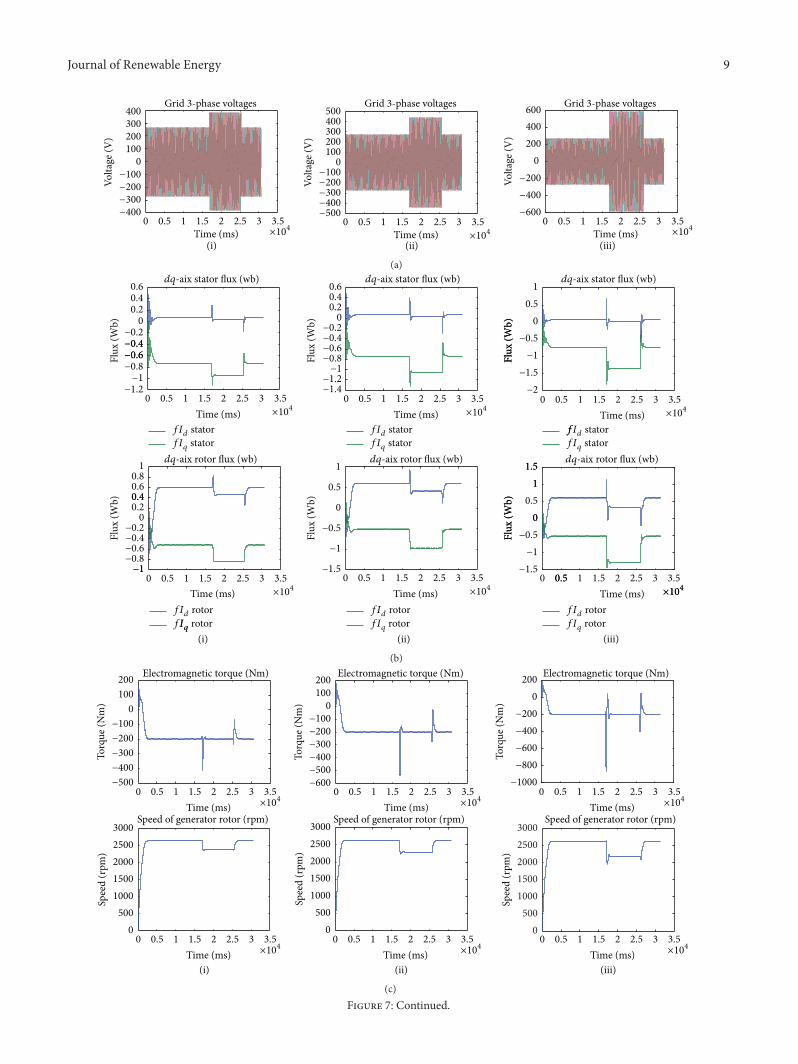