
Research Article Drop-on-Demand Inkjet Printhead...
17
Research Article Drop-on-Demand Inkjet Printhead Performance Enhancement by Dynamic Lumped Element Modeling for Printable Electronics Fabrication Maowei He, 1,2 Liling Sun, 1,2 Kunyuan Hu, 1 Yunlong Zhu, 1 Lianbo Ma, 1 and Hanning Chen 3 1 Department of Information Service & Intelligent Control, Shenyang Institute of Automation, Chinese Academy of Sciences, Faculty Office VII, Nanta Street No. 114, Shenhe District, Shenyang 110016, China 2 University of Chinese Academy of Sciences, Beijing 100049, China 3 School of Computer Science and Soſtware, Tianjin Polytechnic University, Tianjin 300387, China Correspondence should be addressed to Hanning Chen; perfect [email protected] Received 10 October 2014; Accepted 26 November 2014; Published 24 December 2014 Academic Editor: Victor Sreeram Copyright © 2014 Maowei He et al. is is an open access article distributed under the Creative Commons Attribution License, which permits unrestricted use, distribution, and reproduction in any medium, provided the original work is properly cited. e major challenge in printable electronics fabrication is the print resolution and accuracy. In this paper, the dynamic lumped element model (DLEM) is proposed to directly simulate an inkjet-printed nanosilver droplet formation process and used for predictively controlling jetting characteristics. e static lumped element model (LEM) previously developed by the authors is extended to dynamic model with time-varying equivalent circuits to characterize nonlinear behaviors of piezoelectric printhead. e model is then used to investigate how performance of the piezoelectric ceramic actuator influences jetting characteristics of nanosilver ink. Finally, the proposed DLEM is applied to predict the printing quality using nanosilver ink. Experimental results show that, compared to other analytic models, the proposed DLEM has a simpler structure with the sufficient simulation and prediction accuracy. 1. Introduction e ability of inkjet technology to deposit materials with diverse physical and chemical properties on a substrate has made it an exciting technology for mechanical engineering, life sciences, and electronics industry [1]. Low cost metal coating and rapid prototyping are popular applications of inkjet technology in mechanical engineering [2]. In the life science field, it has been used for printing DNA structures and making artificial skin and other important organs by jetting live cells [3, 4]. In the past decade, electronics fabrication using the drop-on-demand (DoD) piezoelectric (PZT) inkjet printhead to print conductive ink on flexible substrates is an enabling technology that will provide desired high-volume, low-cost production of flexible electronic devices, ranging from radio frequency identification (RFID) tags, solar cells, and organic light emitting diodes (OLED) to packaging flexible electronic devices such as healthcare equipment [5– 7]. A typical DoD piezoelectric inkjet printhead comprises a number of ink channels that are arranged in parallel [8]. Each ink channel is connected with a piezoelectric actuator. When applying a standard actuation voltage pulse, the actuator can generate pressure oscillations inside the ink channel to push the ink droplet out of the nozzle. Nowadays the developments of DoD printing are moving towards higher productivity and quality, which require adjustable small droplet sizes fired at high jetting frequencies. Generally, the print quality delivered by an inkjet printhead depends on jetting characteristics, that is, the jetting direction, the droplet velocity, and the droplet volume. However, in order to meet the challenging requirements of printable electronics fabrication, the jetting characteristics of the conductive ink have to be tightly controlled for higher inkjet performance [9]. e performance improvement, which is associated with the design and operation of DoD printhead, is severely hampered by several operational issues, such as residual vibrations and cross talk [10]. Hindawi Publishing Corporation Mathematical Problems in Engineering Volume 2014, Article ID 270679, 16 pages http://dx.doi.org/10.1155/2014/270679
Transcript of Research Article Drop-on-Demand Inkjet Printhead...
Research ArticleDrop-on-Demand Inkjet Printhead PerformanceEnhancement by Dynamic Lumped Element Modelingfor Printable Electronics Fabrication
Maowei He12 Liling Sun12 Kunyuan Hu1 Yunlong Zhu1 Lianbo Ma1 and Hanning Chen3
1Department of Information Service amp Intelligent Control Shenyang Institute of Automation Chinese Academy of SciencesFaculty Office VII Nanta Street No 114 Shenhe District Shenyang 110016 China2University of Chinese Academy of Sciences Beijing 100049 China3School of Computer Science and Software Tianjin Polytechnic University Tianjin 300387 China
Correspondence should be addressed to Hanning Chen perfect chnhotmailcom
Received 10 October 2014 Accepted 26 November 2014 Published 24 December 2014
Academic Editor Victor Sreeram
Copyright copy 2014 Maowei He et al This is an open access article distributed under the Creative Commons Attribution Licensewhich permits unrestricted use distribution and reproduction in any medium provided the original work is properly cited
The major challenge in printable electronics fabrication is the print resolution and accuracy In this paper the dynamic lumpedelement model (DLEM) is proposed to directly simulate an inkjet-printed nanosilver droplet formation process and used forpredictively controlling jetting characteristics The static lumped element model (LEM) previously developed by the authors isextended to dynamic model with time-varying equivalent circuits to characterize nonlinear behaviors of piezoelectric printheadThe model is then used to investigate how performance of the piezoelectric ceramic actuator influences jetting characteristics ofnanosilver ink Finally the proposed DLEM is applied to predict the printing quality using nanosilver ink Experimental resultsshow that compared to other analytic models the proposed DLEM has a simpler structure with the sufficient simulation andprediction accuracy
1 Introduction
The ability of inkjet technology to deposit materials withdiverse physical and chemical properties on a substrate hasmade it an exciting technology for mechanical engineeringlife sciences and electronics industry [1] Low cost metalcoating and rapid prototyping are popular applications ofinkjet technology in mechanical engineering [2] In the lifescience field it has been used for printingDNAstructures andmaking artificial skin and other important organs by jettinglive cells [3 4] In the past decade electronics fabricationusing the drop-on-demand (DoD) piezoelectric (PZT) inkjetprinthead to print conductive ink on flexible substrates is anenabling technology that will provide desired high-volumelow-cost production of flexible electronic devices rangingfrom radio frequency identification (RFID) tags solar cellsand organic light emitting diodes (OLED) to packagingflexible electronic devices such as healthcare equipment [5ndash7]
A typical DoD piezoelectric inkjet printhead comprises anumber of ink channels that are arranged in parallel [8] Eachink channel is connected with a piezoelectric actuator Whenapplying a standard actuation voltage pulse the actuatorcan generate pressure oscillations inside the ink channelto push the ink droplet out of the nozzle Nowadays thedevelopments of DoD printing are moving towards higherproductivity and quality which require adjustable smalldroplet sizes fired at high jetting frequencies Generallythe print quality delivered by an inkjet printhead dependson jetting characteristics that is the jetting direction thedroplet velocity and the droplet volume However in orderto meet the challenging requirements of printable electronicsfabrication the jetting characteristics of the conductive inkhave to be tightly controlled for higher inkjet performance[9] The performance improvement which is associated withthe design and operation of DoD printhead is severelyhampered by several operational issues such as residualvibrations and cross talk [10]
Hindawi Publishing CorporationMathematical Problems in EngineeringVolume 2014 Article ID 270679 16 pageshttpdxdoiorg1011552014270679
2 Mathematical Problems in Engineering
Researchers have developed many approaches to solvethese issues The most typical approaches include usinganalytical or numerical techniques to model the DoD piezo-electric inkjet printhead [12 13] Based on solving the nonlin-ear Navier-Stokes equations numerical modeling of dropletformation process has been focused on the liquid filamentevolution with known pressure input boundary conditionsassumed to be either known or an input correction forcertain specific droplet generator Numerical models areoften programmed in CFD packages using complex meshesand solving techniques This approach provides visualizedinformation about the acoustic pressure wave travellinginside the channel [14] However numerical models are verycomplex and therefore computationally expensive In the lastdecade analytical modeling approach is gradually used todescribe the ink channel dynamics although the accuracyof analytical models is lower than numerical models [15]Based on several assumptions and simplifications analyticalmodels can provide simple and timesaving ways to model-based control droplet generator with a sufficient accuracy Inthis category lumped elementmodeling [16] and feedforwardtwo-port network modeling [17] technique are two typicalanalytic printheadmodels to analyze the acoustic-mechanicalbehaviors of droplet generator
The lumped element modeling (LEM) approach intro-duces an equivalent electric circuit including capacitorsresistors and inductors in series or parallel to describe thedynamics of the ink channel [19] The LEM results explainthe driving force difference between different operatingconditions Lumped element modeling technique has beena suitable method to simulate the operating mechanism ofdroplet generator due to its outstanding advantages suchas moderate model complexity and high simulation speedHowever the accuracy of these classical LEM models islow for the improved performance requirements of printableelectronics fabrication [20] The two-port model is proposedto describe the ink channel dynamics utilizing the conceptof bilaterally coupled systems [21] Each part of dropletgenerator is respectively modeled as a two-port subsystemand finally cascaded into the whole system Compared withLEM technique two-port network owns the advantage of sat-isfactory simulation accuracy and the disadvantages of morecomplex structures and inevitably low simulation speed
This work is aimed at building a dynamic LEM (DLEM)model to characterize nonlinear behaviors of piezoelectricinkjet printhead In the proposed DLEM the linear equiva-lent circuit of piezoceramic in original LEM is replaced intononlinear time-varying capacitance inductance and resistorin series Compared to other analytic models such as two-port network the DLEM has a simpler structure with thesufficient simulation accuracy Additionally the DLEM isused to search the optimal combinations of high-frequencydriving waveform to effectively minimize the residual vibra-tion for nanosilver ink With comparisons of simulation andexperimental results the significant merits of the proposedmethods lie in the following aspects
(1) By applying dynamic nonlinear structure the simula-tion accuracy of LEM is remarkably improvedThat is
the simulation curves of droplet volume and velocitycan well overlap the experimental measurements
(2) The obvious overshoot observed in the outflow curvescan sufficiently indicate the break-off phenomenonwhich divides the droplet formation process intothe meniscus protruding filament breaking-off anddroplet falling-down stages
(3) TheproposedDLEMcan effectively predicate optimalcombinations of high-frequency driving waveformwith high jetting characteristics
The rest of this paper is organized as follows In Section 2a review of original lumped element modeling droplet gener-ator is present and three equivalent circuits are given to char-acterize the nonlinear behaviors of piezoelectric printheadNext a schematic of experimental method is introduced inSection 3 After that the simulation results of droplet volumeand velocity decide the most suitable model in Section 4Theprediction under restrictive condition is built in Section 5Finally discussing and concluding remarks are collected inSection 6
2 Modeling
21 Original Lumped Element Model LEM provides a simplemethod to estimate the low-frequency response of printheadwhich assumes that the characteristic length scales of thegoverning physical phenomena are larger than geometricdimension For example the pressure wave length (in theorder of 100mm) of KM series IJ Head of Konica which isdetermined by the sonic speed of the fluid (about 1400ms)and the highest operation frequency of the droplet generator(128 kHz) is much larger than nozzle diameter (27120583m) Sothis assumption for LEM application is well satisfied
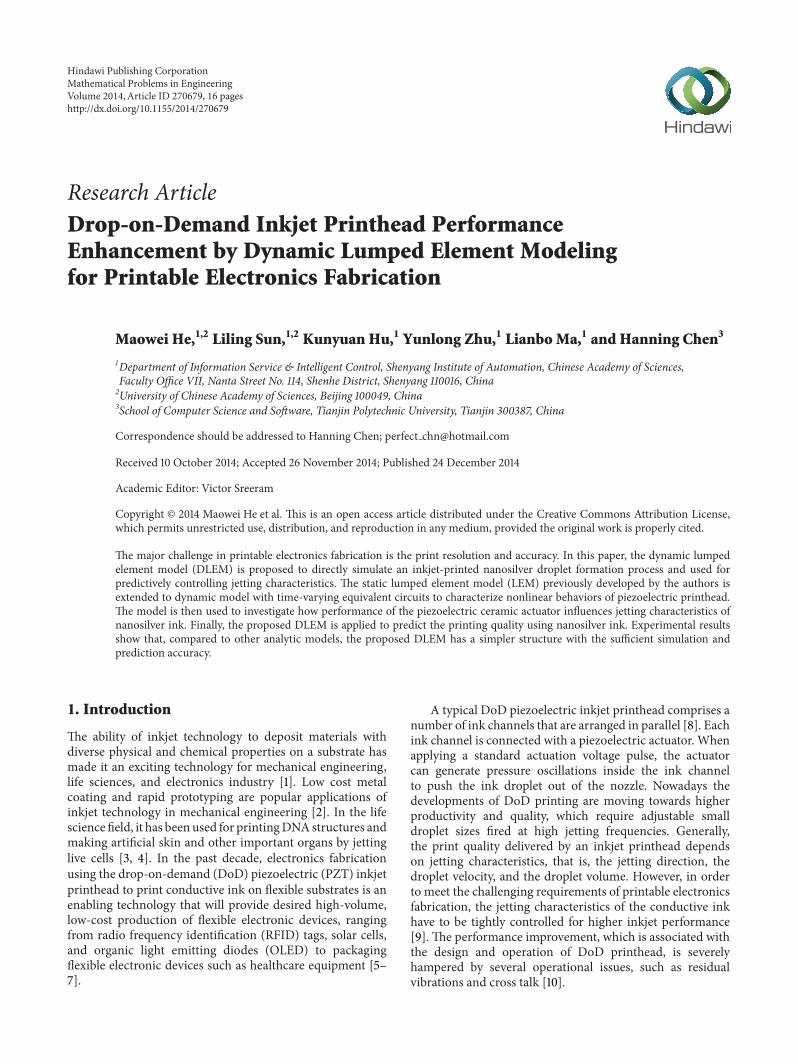
A classical LEM is given to simulate jetting character-istics of PZT printhead by Gallas as shown in Figure 1The equivalent circuit model is constructed by the energystorage elements and ideal dissipative terminal In thiselectroacoustic system pressure and voltage are indepen-dent variables while current and volumetric flow rate aredependent variables Model structure shows that the energyconverts from electrical energy to mechanical energy thento fluidicacoustic energy and finally to kinetic energy asdescribed in Figure 1(b) The droplet generator structure canbe characterized by equivalent acoustic mass (representingstored kinetic energy) and acoustic compliance (represent-ing stored potential energy) in which the correspondingequivalent circuit models are supported by various fluidmechanisms as represented in Figures 1(a) and 1(c) Further-more the piezoceramic model is constructed based on theelectrofluidicacoustic theory [22] The neck model is builton the velocity profile function [23] The nozzle model isconstructed according to the end correction for an open tubetheory [24]
As the equivalent circuit model shown in Figure 1 exci-tation voltage 119881ac is applied to piezoelectric ceramic to createmechanical deformation Coupling coefficient 120601
119886represents
a conversion from mechanical domain to acoustic domain
Mathematical Problems in Engineering 3
Channel Neck Nozzle
Piezoceramic
Piezoceramic
(a)
DropformationNozzleNeckChannel
Drivingwaveform Piezoceramic
Electricaldomain
Mechanicaldomain domain domain domain domain
Fluidicacoustic Fluidicacoustic Fluidicacoustic Kinetic
(b)
Electrical Fluidicacoustic Kineticdomaindomaindomain
sim
Vac
CaCCeb MaRad
QoutMaNRaNMaDRaDCaD1 Na
RaO
(c)
Figure 1 Schematic overview of lumped-element modeling for PZT printhead (a) droplet generator structure (b) model structure and (c)equivalent circuit model
119862eb is the blocked electrical capacitance of the piezoelectricmaterial In the acoustic domain 119862aD and 119862aC representthe acoustic compliance of piezoceramic and channel 119877aD119877aN and 119877aO are the acoustic resistance due to structuraldamping neck tapering and fluid flowing out of nozzlerespectively 119872aD 119872aN and 119872aRad represent the acousticmass of piezoceramic neck and nozzle in proper orderrespectively
The dimensions of droplet generator and physical proper-ties of nanosilver ink provided by the LEED-PV Corporationare listed in Table 1 and calculation formulas of LEM modelparameters are provided in Table 2
According to above lumped element model a transferfunction describing the response relationship between theflow rate119876out and input AC voltage119881ac is obtained as follows
119876out (119904)
119881ac (119904)=
120601119886119862aD119904
11988641199044 + 119886
31199043 + 119886
21199042 + 119886
11199041 + 1
(1)
where
1198861= 119862aD (119877aO + 119877aN + 119877aD) + 119862aC (119877aO + 119877aN)
1198862= 119862aD (119872aRad +119872aN +119872aD) + 119862aC (119872aRad +119872aN)
+ 119862aC119862aD119877aD (119877aO + 119877aN)
1198863= 119862aC119862aD [119872aD (119877aO + 119877aN) + (119872aRad +119872aN) 119877aD]
1198864= 119862aC119862aD119872aD (119872aO +119872aN)
(2)
The frequency response of droplet generator driven bythe sinusoidal signal as shown in Figure 2 reveals thatnatural frequency (around 486 kHz) is higher than operating
2 4 6 8 100
5
10
15
20
Frequency (Hz) times104
Vm
axV
norm
Figure 2 Frequency response of lumped element model
frequency (below 128 kHz) This means that the meniscuscan obtain sufficient energy to overcome viscosity and surfacetension and then to generate consistent droplets
As the above simulation models 119862aD 119877aD and 119872aD areregarded as static parameters based on the approximate linearbehaviors of piezoelectric ceramic with a fix path of P-Ehysteresis loop However in fact the piezoelectric ceramic isa nonlinear material with multiple electric fieldstrain curves(parallel and perpendicular to the field) as shown in Figure 3It has been proved that the above original static modelhas insufficient ability to simulate the piezoelectric ceramicdynamic response in time-domain below linear voltage [11]
Our research finds that the maximum error between theexperimental measurements and simulation results can reacheight percent Additionally when the break-off phenomenon
4 Mathematical Problems in Engineering
Table 1 Droplet generator parameters
Parameter Unit Value
Geometry
Channel volume 1198810
Pl 166000Channel length 119871
0Um 7200
Nozzle radius 1198860
Um 135Neck length 119871 Um 45
PZT Piezoceramic thickness ℎ Um 25Free electrical capacitance 119862ef F 28 nF
Fluid
Surface tension 120590 Nm 45 lowast 10minus3
Viscosity 120583 Kg(mlowasts) 15Density 120588
0Kgm3 105 lowast 103
Sonic speed 1198880
ms 1400
Table 2 Lumped elements modeling parameter estimation
LEM Description
Neck 119877aN 119877aN = (2 +1198860
119903)radic2120583120588
0120596
1205871199032 where 119906 is viscosity 119908 is wave frequency and 119886
0119903 is gradients ratio
119872aN 119872aN =1205880(119905 + Δ119905)
1205871199032 where Δ119905 = 085119903(1 minus 07(119903119886
0)) + 085119903
Cavity 119862aC 119862aC =1198810
120588011988820
where 1198810is volume of the cavity
Piezoelectric119862aD 119862aD =
1205871199036
(1 minus V2)16119864ℎ3
where 119864 is the elastic modulus V is Poissonrsquos ratio and ℎ is the thickness
119872aD 119872aD =41205880119871
312058711988620
119877aD 119877aD = 2120585radic119872aD +119872aRad
119862aD where 120585 is the experimentally determined damping factor [18]
Nozzle119877aO 119877aO =
12058801198880
1205871199032[1 minus
21198691(2119896119903)
2119896119903] where 119869
1is the Bessel function of the first kind and 119896 = 119908119888
0
119872aRad 119872aRad =81205880
312058721198860
119862eB 119862eB = 119862eF(1 minus 1205812
) where 1205812 is electroacoustic coupling factor
1 2
e
1
2
3
4
abc
d
x1
x3
minus1
minus1
minus2
times10minus3
Δll
E (kVmm)
Figure 3 Possible paths of P-E hysteresis loop for piezoceramicmaterial [11]
occurs part of filament would go back into the nozzle andthe droplet volume will have a certain decrease But thesimulation curves of droplet volume with original modelhave no obvious sign to show that the break-off phenomenonoccurs (please refer to the simulation results in Section 42)
C0 R1
L1
C1
Figure 4 Equivalent electrical circuitmodel of PZTnonlinear effectwith proportional coefficient
22 Improved LEM with Nonlinear Equivalent Circuits Inorder to resolve above problems in this section threeequivalent circuits with different characters are incorporatedinto the classical LEM to characterize the nonlinear effect ofthe piezoelectric ceramics
(1) Proportional Model In order to describe the nonlinearrelationship between electric field and strain a proportionalmodel (illustrated in Figure 4) as a resonance was defined inthe IEEE standards publication [25] This analytical model is
Mathematical Problems in Engineering 5
C0
C2
C1 R1 L1
R2 L21 N
Figure 5 Equivalent electrical circuitmodel of PZTnonlinear effectwith multiple parallel resonances
derived based on the constitutive relations of piezoelectricityand the following assumptions (a) Euler-Bernouli beamassumption [26] (b) negligible external excitation from airdamping (c) proportional damping (ie the strain ratedamping and viscous damping are assumed to be propor-tional to the bending stiffness and mass per length of thebeam) (d) uniform electric field through the piezoelectricthickness Then the circuit element values of the proposedlumped parameter model are formulated in (1) where T isthe adjustment coefficient
1198711=
119871119898
T2
1198771=
119877119898
T2
1198621= T2 lowast 119862
119898
(3)
(2) Multiple-Resonator Model Yang and Tang [27] givethe multiple-resonator model to characterize piezoelectricceramic in piezoelectric energy harvesters as shown inFigure 5 His research finds that the network of piezoelectricceramic driving circuit consists of infinite branches and eachis composed of simplified equivalent circuit with an inductora capacitor and a resistorWhen the voltage signals from sev-eral branches drive the piezoelectric ceramic simultaneouslythe higher order vibrationmodes are excited It is realized thatworking at higher order modes causes the nonlinear effectof piezoelectric ceramic To characterize the different higherorder modes a circuit of multiple resonators is constructedto match the external branches In this literature to modelthe droplet generator nearly a double circuit may meet thesimulation accuracy Then the circuit element values of theproposed lumped parameter model are formulated in (3)where 120572 and N are both the adjustment coefficients
1198622=
1198621
1205722
1198772= 120572 lowast 119877
1
1198712= 1198711
(4)
(3) Dynamic Model Based on the works in [28 29] an equiv-alent electrical circuit with nonlinear resonance oscillationsin series namely the dynamic model is given to analyzepower BAW (bulk acoustic wave) resonators as shown inFigure 6Three major nonlinear effects are considered in this
C0 C0
C1
C2
C3
R1
L1
L1
R2
R3
C(I)
R(I)
Figure 6 Equivalent electrical circuitmodel of PZTnonlinear effectwith dynamic coefficients
equivalent circuit the amplitude-frequency effect (A-F effect)[30] the intermodulation effect [31] and the bias-frequencyeffect (B-F effect) [32] The dynamic values of resistance andcapacitance in the motional branch are dependent on themotional current in the branchThen derivation formulas aregiven in (4) where A
1 A2 B1 and B
2are the adjustment
coefficients
1198622= 12057211198682
1198623= 12057221198684
1198772= 12057311198682
1198773= 12057321198684
997904rArr 119862 (119868) = 119862
1(1 + A
11198682
+ A21198684
)
119877 (119868) = 1198771(1 + B
11198682
+ B21198684
) (5)
Then the improved LEM structure can be illustrated as inFigure 7
3 Experimental Method
31 Experimental Setup In this experiment the investigatedprinthead is KM series IJ Head of Konica and the used ink isnanosilver ink provided by the LEED-PV Corporation andthe according parameters are listed in Table 1 in Section 2 Aschematic overview of the experimental setup to observe thenanosilver droplet formation process is shown in Figure 8The visualization system consists of a cold source of halogens(XAO LG150) and a CCD camera (SVS ECO424) whichcan synchronize to the driving signal The volume andvelocity of droplet and the profile of meniscus are measuredthrough the images captured by CCD with exposure time of1 us The high-frequency driving waveform is programmedby arbitrary wave generator (RIGO DG2014A) In orderto repeatedly generate uniform droplets ink supply unitconnects air pressure unit which offers suitable negative forceto prevent the ink leaking from the printhead
32 Edge Detection and Image Analysis as a QualitativeMeasure The leading edge detection is to determine thenozzle position and meniscus position A straight line isgenerated along the nozzle in the region of interest (ROI)with
6 Mathematical Problems in Engineering
sim
Vac
CaCCeb
MaRadMaNRaN
MaDRaDCaD1 Na
RaO
(a)
sim
Vac
CaCCeb
MaRadMaNRaN
1 NaRaDT
2MaDT
2
RaO
CaDT2
(b)
sim
Vac
CaC
Ceb
MaRadMaNRaN
MaD
MaD
RaDCaD
1 Na
1 N
CaDa2
aRaD
RaO
(c)
sim
Vac
CaCCeb
MaRadMaNRaN
MaD1 Na C(I) R(I)
RaO
(d)
Figure 7 (a) Original LEM (b) proportional coefficient model (c) multiple resonators model and (d) dynamic coefficients model
Temperature unit
Air pressure unit
Ink supply
Parallel
Halogens light source
CCDPC
Wave generator
Drivingboard
Image
(a)
CCD
Halogens light
sourceArbitrary waveform generator
Drivingboard
PrintheadInk supply
(b)
Figure 8 Experimental setup (a) schematic of experimental setup and (b) image of experimental setup
CCD camera image analysis By setting a suitable thresholdgradient of brightness themeniscus location can be detectedThe satellite droplets and filament can be detected throughfarther image processing such as cropping filtering andthreshold recontrasting (shown as in Figure 9)
In image analysis system the droplet volume is calculatedby
Vol = sum120587 sdot (119889
2)
2
sdot 120575119911 (6)
which hypothesizes that liquid jet is axis-symmetric alongnozzle centerline And the droplet velocity is calculated basedon the position change of the moving-forward leading edgein two consecutive images with specified sampling intervalNote that the information is lost if the meniscus is hiddeninside the nozzle so edge detection only measures theprotruding meniscus
33 High-Frequency Driving Waveform as a System Excita-tion The high-frequency driving waveform is composed of
positive and negative periods including three pulse edges andtwo dwell times as shown in Figure 10 The first rising edgeexpands the channel to get the inkmeniscus into the channelThen the falling edge works to eject the droplet from thenozzle
This period of waveform design is based on the halfperiod of channel resonance Thus the waveform designissue is focused on calculating the optimum value of dwelltime 119879
1= 1198710119862 where 119871
0is the length of channel and 119862
is the sonic speed of the used ink The falling edge of thesecond negative voltage generates larger pressure in channelto accelerate the droplet with higher speed than conventionalsingle trapezoidal waveform The second rising edge whichsets the voltage back to 0 works to restrain the meniscusvibration [33]
Theoretically the suitable slops of the rising edge andfalling edge can restrain the meniscus vibration [34] How-ever in practical applications these two values are too largeto control accurately
Asmentioned above theoretical optimum value for dwelltime 119879
1is set as 52 us The corresponding dwell time 119879
2
Mathematical Problems in Engineering 7
(a) (b) (c) (d)
Figure 9 Image processing steps (a) original image (b) cropped image (c) threshold image and (d) edge image
Time
Voltage
Dwell
Dwell
time T1
time T2
Figure 10 Applied driving waveform of printhead
is recommended as 104 us (twice of 1198791) and the voltage
magnitude is set as 12 V according to the instruction ofKonica printhead In this paper the driving waveform withthese parameters is called the ldquostandardrdquo waveform [35]
4 Simulation Result
41 Coefficient Identification The coefficients of originalLEM model can be determined experimentally Howeverthe three improved models in this work are somewhatcomplicated and their coefficients reveal some importantfeatures of these equivalent circuits For this reason thissection is dedicated to identify the adjustment coefficients inthese corresponding circuits
In this experiment a group of experimental measure-ments with printhead driven by the standard high-frequencywaveform are chosen as the basic reference The coeffi-cients of each proposed improved LEM model should beadjusted to minimize the deviations between the simulationresults and the selected experimental measurements shownin Figure 11 The nonlinear least squares method [36] usingthe Levenberg-Margquardt and Gauss-Newton Algorithms
Table 3 Coefficients for three lumped element models
Model Coefficient ValueProportional 119879 0837
Multiple resonators 120572 51119873 228
Dynamic coefficients
1198601
133 lowast 103
1198611
353 lowast 103
1198602
234 lowast 104
1198612
411 lowast 104
is applied to find the optimal coefficients set for each pro-posed equivalent circuit which makes the simulation curvesoverlap the experimental measurements as far as possibleThe resulting coefficients are listed in Table 3
42 Droplet Volume Simulation In many applications of ink-jet printing the volume of droplet is a critical restrictivecondition Droplets with controllable volume affect not onlythe printing resolution but also the depositional thicknessTherefore how to accurately control droplet volume is a keyproblem to be solved by the proposed method
According to experimental measurements in Figure 11the comparison between the original LEM model and theproposed three improved models is presented in Figure 12In this figure the solid line is the outflow simulation curvesbased on the LEM technique and the star line is the actualmeasured volume values during the droplet formation pro-cess It should be noted that in Figures 12(a)ndash12(d) the firstthree points of actual measurement curve are default to zerobecause no fluid flowing outside the nozzle can be capturedby our image system
As the actual experimental measurements indicated inFigure 11 the droplet formation process is divided into threestages the meniscus protruding stage (ie 119879
1st = 15sim30 us)the filament breaking-off stage (ie 1198792nd = 30sim35 us) andthe droplet falling-down stage (ie 1198793rd = 35sim60 us) That
8 Mathematical Problems in Engineering
3us0pL0ms
6us0pL0ms
9us0pL0ms
12us 15us 18us 21us 24us
30us 33us 36us 39us 42us 45us 48us27us
678pL876ms
994pL730ms
1221 pL684ms
1401pL624ms
1521pL618ms
1533pL600ms
1567pL600ms
1509pL606ms
1492pL618ms
1489pL624 ms
1480 pL624 ms
1479pL618ms
1480pL618ms
Figure 11 Pictures of nanosilver droplet formation process driven by standard waveform
is ideally the outflow curve simulated by analytic modelsshould include overshoot phase which can clearly demon-strate that the part of filament is inhaled back into nozzle orsplits into satellite droplets by viscosity and surface tensionin the filament break-off stage However according to thesimulation result of the original LEM in Figure 12(a) there
is no obvious decreasing after reaching the maximum in theoutflow curve and the outflow curve of the original modelcannot well overlap the actual measurement curve
In Figures 12(b) and 12(d) the overshoot phase canbe observed clearly This performance improvement can bestraightforwardly explained by the fact that poles and zeros
Mathematical Problems in Engineering 9
0 20 40 60
0
10
20
Time (us)
Volu
me (
pL)
ExperimentOriginal
minus10
(a)
0 20 40 60
0
10
20
Time (us)
Volu
me (
pL)
ExperimentProportional
minus10
(b)
0 20 40 60
0
10
20
Time (us)
Volu
me (
pL)
ExperimentMultiple
minus10
minus20
(c)
0 20 40 60
0
10
20
Time (us)
Volu
me (
pL)
ExperimentDynamic
minus10
(d)
Figure 12 Outflow change ofmeasurements and simulations of (a) original model (b) proportional coefficientmodel (c)multiple resonatorsmodel and (d) dynamic coefficient model
of the transfer functions are manipulated to speed up thedynamic response speed of the proportional and dynamicmodels From Figure 12 both the multiple-resonator anddynamic models can obtain precise simulation results Thatis more well-designed coefficients are used to characterizethe nonlinear behaviors of piezoelectric printhead and theadjustable ranges are extended to a satisfied degree of bothmodels Additionally it should be noted that the outflowcurve of dynamic model has not only the overshoot phasebut also high overlap ratio to the experimental measurementMoreover the simulation curves reveal that the meniscusmoves inward before the droplet appears
43 Flow and Droplet Velocity Simulation The velocity ofdroplet is the other important aspect to evaluate the printingeffect Droplets with a high speed can remarkably improve
the printing efficiency and the quality of impact with sub-strate Therefore this experiment gives the velocity simula-tion using the proposed LEM models on the same actualexperimental measurement in Section 41
The comparisons between the flow velocity curves sim-ulated by the original LEM and three improved models areillustrated in Figure 13 The excitation is the standard drivingwaveform For the actual measured velocity curves the firsttwo points are also default to zero because no fluid flowingoutside the nozzle can be captured by our image system
It should be noted that all the values of actual measuredvelocity are positive However from the flow velocity curvesin Figure 13 the values of flow velocity in nozzle can bepositive or negative in different phases This positive-to-negative velocity variation indicates the changes of the flowdirection that leads to the break-off phenomenon Hence in
10 Mathematical Problems in Engineering
0 20 40 60
0
5
10
Time (us)
Velo
city
(ms
)
ExperimentFlow velocityOriginal
minus10
minus5
(a)
0 20 40 60
0
5
10
Time (us)
Velo
city
(ms
)
ExperimentFlow velocityProportional
minus10
minus5
(b)
0 20 40 60
0
5
10
Time (us)
Velo
city
(ms
)
ExperimentFlow velocityMultiple
minus10
minus5
(c)
0 20 40 60
0
5
10
Time (us)
Velo
city
(ms
)
ExperimentFlow velocityDynamic
minus10
minus5
(d)
Figure 13 Comparison of measured droplets velocity and the flowaverage velocity simulated by (a) original model (b) ldquoproportionalcoefficientrdquo model (c) ldquomultiple resonatorsrdquo model and (d) ldquodynamic coefficientsrdquo model
order to correctly simulate the velocity in leading edge wepropose a new calculation formula which combines both ofoutflow curve and flow velocity curve
119881average (119905) = radicsum1199052
119905=1199051
(12) 119876out (119905) sdot 119881 (119905)2
sum1199052
119905=1199051
(12)119876out (119905) (7)
where119876out is the outflow value and119881 is the flow velocity 1199051is
the moment when the sum of 119876out changes from negative topositive in outflow curve and 119905
2after 119905
1is the moment when
flow velocity changes to negative in nozzleFrom Figure 13 it can be obviously observed that in
the beginning of droplet formation process the multiple-resonator and dynamic models exhibit better performance insimulating the droplet velocity rather than the originalmodelThat is the average velocity curves obtained by these two
models are almost coincident to the actual measured velocitycurves
Based on the above analysis and comparisons thedynamicmodel based LEMhas themost accuracy in simulat-ing the droplet volume and velocity and can carry sufficientinformation to distinguish the break-off phenomenon occur-ing in the nanosilver droplet formation processs Thereforeamong these three improved models the dynamic lumpedelement model (DLEM) is the most suitable improved equiv-alent structure for simulating jetting characteristics
5 Prediction
For industry applications in printable electronics fabricationthe printhead must work at a certain status to meet manyrestrictive conditions Among them the most important
Mathematical Problems in Engineering 11
0 20 40 60
0
5
10
15
20
Time (us)
Volu
me (
pL)
minus25
minus20
minus15
minus10
minus5
T1 = 3usT1 = 4usT1 = 5us
T1 = 6usT1 = 7usT1 = 8us
(a)
0 20 40 604
5
6
7
8
9
10
Velo
city
(ms
)
Time (us)
T1 = 3usT1 = 4usT1 = 5us
T1 = 6usT1 = 7usT1 = 8us
(b)
Figure 14 Predictive droplet volume and velocity with different and various dwell times 1198792= 21198791 (a) simulation curves of outflow change
and (b) simulation curves of droplet average velocity
4 6 813
14
15
16
17
SimulationExperiment
Volu
me (
pL)
Time (us)
(a)
SimulationExperiment
4 6 8
45
5
55
6
Time (us)
Velo
city
(ms
)
(b)
Figure 15 Predictive droplet volume and velocity compared with measured volume and velocity
problem is choosing the appropriate combinations of thedriving waveform parameters for the used conductive inksHowever an exhausting manual selective process inevitablywastes a lot of time Therefore the computer-aided methodsare urgently needed for searching these appropriate combi-nations efficiently and robustly In this section the proposed
DLEM is applied to predict jetting characteristics for nanosil-ver ink
51 General Prediction Procedure The general procedure ofdroplet volumevelocity prediction based on DLEM is asfollows
12 Mathematical Problems in Engineering
0us0pL0ms
3us0pL0ms
6us0pL0ms
9us0pL0ms
12us6353pL736ms
15us9318pL612ms
18us11441pL572ms
18us 24us
30us14364pL498ms
33us14046pL510ms
36us13980pL520ms
39us13952pL525ms
42us13858pL525ms
45us13869pL520ms
48us13891pL524ms
51us13924pL522ms
54us
524ms13877pL
57us13840pL530ms
13127 pL548ms
14252pL520ms
27us14786pL504ms
Figure 16 A sequence of pictures of droplet falling from nozzle
Step 1 According to droplet generator parameters and prop-erties of fluid calculate most of the parameters in DLEM
Step 2 According to experimental measurements of dropletvolume driven by a standard waveform determine the rest ofthe adjustment coefficients and damping coefficients
Step 3 Based on the constructed DLEM predicate the valuesof droplet volume and velocity
Step 4 According to the need of applications and restrictiveconditions find out several groups of the appropriate param-eters of driving waveform frompredictive data lists of volumeand velocity
Step 5 After making a subtle adjustment in practice decidethe most appropriate parameters of driving waveform
52 Prediction Case 1 Standard Waveform with DifferentDwell Time Asmentioned above theDLEMmodel is chosento simulate jetting characteristics for the nanosilver inkHere an illustrative example is given to display the effect of
predicting the typical combinations of waveform parameterswith different dwell times (119879
1= 3sim8 us 119879
2= 2119879
1) and
the same amplitude (12V) The properties of nanosilver inkprovided by the LEED-PV Corporation have been listed inTable 1
In Figure 14 the predicted outflow and average velocitycurves with various dwell times are depicted We can observefrom Figure 14(a) that before the droplets rush out of thenozzle the depth of the inhaled meniscus is proportionalto dwell time From Figure 14(b) the time of the dropletappearing is postponed with the increase of dwell timeThat is both two simulation phenomena consist with thetheoretical analysis results in [37]
The comparisons between actual measured and predictedjetting characteristics with various dwell times are given inFigures 15(a) and 15(b) which both illustrate a parabolicchange rule with the increase of dwell time It should benoted that at the dwell time 119879
1= 56 us near the theoretical
optimum value 11987910158401= 52 us the droplet volume and velocity
simultaneously reach the maximum From the performanceof prediction accuracy listed in Table 4 the deviation of thepredicted jetting characteristics is within acceptable range
Mathematical Problems in Engineering 13
45
67
68
1012
1416
10121416
Volu
me (
pL)
91011121314151617
T1 (us)
T2(us)
(a)
45
67
68
1012
1416
3
4
5
6
Velo
city
(ms
)
3
35
4
45
5
55
6
T1 (us) T2
(us)
(b)
Figure 17 Predictive droplet volume and velocity with various dwell times1198791and119879
2 (a) predictive droplet volume and (b) predictive droplet
velocity
53 Prediction Case 2 Driving Waveform under RestrictiveCondition In this experiment an illustrative example underrestrictive conditions is presented to demonstrate the feasibil-ity and effectiveness of the proposed method for predictingjetting characteristics The dimensions of droplet generatorand properties of the nanosilver ink are listed in Table 1 Inorder to reach a high printing resolution and good quality ofdroplet impact with the substrate the restrictive conditionsinvolve that the droplet volume is smaller than 14 pL and thedroplet velocity is larger than 5ms
Based on the prediction procedure the predictive valuesof drop volumevelocity with various dwell times 119879
1and
1198792are listed in Table 5 According to the restrictive con-
ditions three combinations of parameters are found out1198791
= 5 us1198792
= 13 us 1198791
= 55 us1198792
= 14 us and1198791= 5 us119879
2= 75sim8 us After a small range search around
predictive values in the actual test the combination of 1198791=
49 us1198792
= 77 us is finally chosen The dynamic effect ofjetting characteristics driven by this combination is shown inFigure 16 From this figure the jetting characteristics satisfythe specified restrictive conditions quite well Meanwhilealmost no satellite droplet emerges after jetting the maindroplet
The 3D plot of predictive jetting characteristics withvarious dwell times 119879
1and 119879
2is shown in Figure 17 With
the increase of dwell time 1198791 peak positions of volume and
velocity have a tiny shift in 95sim115 us With the same dwelltime 119879
2 there is also a parabolic profile in predictive volume
and velocity
6 Conclusion
The lumped element modeling based on linear model ofpiezoelectric ceramic has been successfully used to simu-late piezoelectric droplet generator However the nonlinearmodel of piezoelectric ceramic is necessary to diminishdeviation between the simulated and measured results Inorder to characterize the nonlinear behavior of piezoelectric
Table 4 Performance of prediction accuracy
Deviation Value
Volume
Max 07135 (499)Min 0036 (013)Mean 02636Std 03316
Velocity
Max 02465 (502)Min 00143 (025)Mean 01095Std 01350
ceramic three models are introduced to simulate dropletgeneration In this work the droplet volumevelocity curvessimulated by dynamic model can carry sufficient informa-tion to distinguish nanosilver droplet formation processclearly Although the complexity of system increases theoutflow curves can obviously reflect the filament breaking-off stage that occurs which is coincident with sampledimages Such nonlinear LEM model is also successful inpredicting jetting characteristics under restrictive conditionsComparing the droplet volumevelocity curves with differentdwell time of high-frequency driving waveform the linearrelationship between dwell time and meniscus appearingmoment is discovered Meanwhile a parabolic change ruleof volumevelocity with the increase of dwell time is in goodagreement with present theoretical analysis
It should be noted that the proposed nonlinear model isfocused on relationship between the droplet volumevelocityand the dwell time of driving waveform while the voltageamplitude is also a decisive factor to droplet formationprocess This should be discussed in our future work
Conflict of Interests
The authors declare that there is no conflict of interestsregarding the publication of this paper
14 Mathematical Problems in Engineering
Table5Predictiv
edropletvolume(pL
)and
velocity(m
s)
1198791
1198792
665
775
885
995
10105
11115
12125
13135
14145
15155
4119881
11119
127
134
139
143
146
149
151
15147
142
Default
Default
Default
Default
Default
Default
Default
Default
119878371
395
417
439
459
478
491
500
489
471
451
435
Default
Default
Default
Default
Default
Default
Default
Default
45 119881
Default
117
125
134
143
15155
159
162
16157
153
147
139
Default
Default
Default
Default
Default
Default
119878Default
421
451
476
498
516
532
548
560
543
523
501
482
466
Default
Default
Default
Default
Default
Default
5119881
Default
Default
Default
133
143
151
157
163
167
168
166
163
157
15142
133
Default
Default
Default
Default
119878Default
Default
Default
480
507
531
553
572
587
600
583
563
540
525
509
498
Default
Default
Default
Default
55 119881
Default
Default
Default
Default
Default
151
159
165
168
169
171
169
165
16154
146
138
129
Default
Default
119878Default
Default
Default
Default
Default
524
550
572
593
609
624
601
571
551
537
523
509
496
Default
Default
6119881
Default
Default
Default
Default
Default
Default
Default
158
163
164
165
165
165
158
1495
141
130
119
108
97119878
Default
Default
Default
Default
Default
Default
Default
495
515
533
549
564
544
519
494
474
458
445
432
421
65 119881
Default
Default
Default
Default
Default
Default
Default
Default
Default
155
159
16155
150
143
134
125
114
103
95119878
Default
Default
Default
Default
Default
Default
Default
Default
Default
473
485
495
503
490
469
446
420
400
390
383
7119881
Default
Default
Default
Default
Default
Default
Default
Default
Default
Default
125
135
139
141
135
127
119
110
102
94119878
Default
Default
Default
Default
Default
Default
Default
Default
Default
Default
445
465
479
463
444
422
401
385
370
363
Defaults
areb
ecause
thec
ombinatio
nsof
parametersindrivingwaveform
areo
utof
theo
peratio
nrange
Mathematical Problems in Engineering 15
Authorsrsquo Contribution
Maowei He and Liling Sun contributed equally to this work
Acknowledgment
This research is partially supported by National Natural Sci-ence Foundation of China under Grants 61105067 7100107261174164 and 71271140
References
[1] M SinghHMHaverinen PDhagat andG E Jabbour ldquoInkjetprinting-process and its applicationsrdquo Advanced Materials vol22 no 6 pp 673ndash685 2010
[2] E Macdonald R Salas D Espalin et al ldquo3D printing for therapid prototyping of structural electronicsrdquo IEEE Access vol 2pp 234ndash242 2014
[3] S Umezu T Kitajima H Murase H Ohmori K Katahiraand Y Ito ldquoFabrication of living cell structure utilizing electro-static inkjet phenomenardquo in Proceedings of the 22nd IEEEInternational Conference on Micro Electro Mechanical Systems(MEMS rsquo09) pp 419ndash422 IEEE Sorrento Italy January 2009
[4] P Cosseddu L Basirico A Loi et al ldquoInkjet printed OrganicThin Film Transistors based tactile transducers for artificialrobotic skinrdquo in Proceedings of the 4th IEEE RAS and EMBSInternational Conference on Biomedical Robotics and Biomecha-tronics (BioRob rsquo12) pp 1907ndash1912 June 2012
[5] J Hwang A Wan and A Kahn ldquoEnergetics of metal-organicinterfaces new experiments and assessment of the fieldrdquoMate-rials Science and Engineering R Reports vol 64 no 1-2 pp 1ndash312009
[6] B J Kang and J H Oh ldquoGeometrical characterization of inkjet-printed conductive lines of nanosilver suspensions on a polymersubstraterdquoThin Solid Films vol 518 no 10 pp 2890ndash2896 2010
[7] F Villani P Vacca G Nenna et al ldquoInkjet printed polymerlayer on flexible substrate for OLED applicationsrdquo The Journalof Physical Chemistry C vol 113 no 30 pp 13398ndash13402 2009
[8] J-C Liou and F-G Tseng ldquoMulti-dimensional data registrationCMOSMEMS integrated inkjet printheadrdquo MicroelectronicEngineering vol 88 no 6 pp 888ndash901 2011
[9] J Miettinen K Kaija M Mantysalo et al ldquoMolded substratesfor inkjet printed modulesrdquo IEEE Transactions on Componentsand Packaging Technologies vol 32 no 2 pp 293ndash301 2009
[10] K Silverbrook ldquoPrinthead with multiple actuators in eachchamberrdquo US7708387 B2 2010
[11] V Piefort Finite element modelling of piezoelectric active struc-tures [PhD thesis] Department ofMechanical Engineering andRobotics Universite Libre de Bruxelles Brussels Belgium 2001
[12] L Sang Y Hong and F Wang ldquoInvestigation of viscosity effecton droplet formation in T-shaped microchannels by numericaland analytical methodsrdquo Microfluidics and Nanofluidics vol 6no 5 pp 621ndash635 2009
[13] J Liu S-H Tan Y F Yap M Y Ng and N-T NguyenldquoNumerical and experimental investigations of the formationprocess of ferrofluid dropletsrdquo Microfluidics and Nanofluidicsvol 11 no 2 pp 177ndash187 2011
[14] F Sarrazin K Loubiere L Prat C Gourdon T Bonometti andJ Magnaudet ldquoExperimental and numerical study of dropletshydrodynamics in MicroChannelrdquo AIChE Journal vol 52 no12 pp 4061ndash4070 2006
[15] X Q Xing D L Butler S H Ng Z Wang S Danyluk and CYang ldquoSimulation of droplet formation and coalescence usinglattice Boltzmann-based single-phasemodelrdquo Journal of Colloidand Interface Science vol 311 no 2 pp 609ndash618 2007
[16] Q Gallas R Holman T Nishida B Carroll M Sheplak and LCattafesta ldquoLumped element modeling of piezoelectric-drivensynthetic jet actuatorsrdquoAIAA Journal vol 41 no 2 pp 240ndash2472003
[17] A A Khalate X Bombois R Babuska H Wijshoff and RWaarsing ldquoOptimization-based feedforward control for a Drop-on-Demand inkjet printheadrdquo in Proceedings of the AmericanControl Conference (ACC rsquo10) pp 2182ndash2187 Baltimore MdUSA July 2010
[18] L Meirovitch Fundamentals of Vibrations McGraw-Hill NewYork NY USA 2001
[19] H Seitz and J Heinz ldquoModelling of a microfluidic device withpiezoelectric actuatorsrdquo Journal of Micromechanics and Micro-engineering vol 14 no 8 pp 1140ndash1147 2004
[20] S Kim J Sung andMH Lee ldquoPressure wave and fluid velocityin a bend-mode inkjet nozzle with double PZT actuatorsrdquoJournal of Thermal Science vol 22 no 1 pp 29ndash35 2013
[21] G Wassink Inkjet printhead performance enhancement by feed-forward input design based on two-port modeling [PhD thesis]Delft University of Technology 2007
[22] S Prasad SHorowitz QGallas B Sankar L Cattafesta andMSheplak ldquoTwo-port electroacoustic model of an axisymmet-ric piezoelectric composite platerdquo in Proceedings of the 43rdAIAAASMEASCEAHS Structures Structural DynamicsandMaterials Conference AIAA Paper 2002-1365 AIAA DenverColo USA April 2002
[23] D T BlackstockFundamentals of Physical Acoustics JohnWileyamp Sons New York NY USA 2000
[24] F M White Fluid Mechanics McGraw-Hill New York NYUSA 1979
[25] H Schempt andD R Yoerger ldquoStudy of dominant performancecharacteristics in robot transmissionsrdquo Journal of MechanicalDesign Transactions Of the ASME vol 115 no 3 pp 472ndash4821993
[26] E A Witmer ldquoElementary Bernoulli-Euler beam theoryrdquoMITUnified Engineering Course Notes vol 5 pp 114ndash164 1991-1992
[27] Y Yang and L Tang ldquoEquivalent circuit modeling of piezoelec-tric energy harvestersrdquo Journal of Intelligent Material Systemsand Structures vol 20 no 18 pp 2223ndash2235 2009
[28] F Constantinescu A G Gheorghe and M Nitescu ldquoNewcircuit models of power BAW resonatorsrdquo in Proceedings of theEuropean Microwave Integrated Circuit Conference October2007
[29] A Albareda and R PerezNon-Linear Behaviour of PiezoelectricCeramics vol 140ofSpringer Series inMaterials Science Springer2011
[30] J Nosek ldquoDrive level dependence of the resonant frequency inBAW quartz resonators and his modelingrdquo IEEE TransactionsonUltrasonics Ferroelectrics and Frequency Control vol 46 no4 pp 823ndash829 1999
[31] R Aigner N-H Huynh M Handtmann and S MarksteinerldquoBehavior of BAW devices at high power levelsrdquo in Proceedingsof the IEEE MTT-S International Microwave Symposium pp429ndash432 Long Beach Calif USA June 2005
[32] R S Ketcham G R Kline and K M Lakin ldquoPerformanceof TFR filters under elevated power conditionsrdquo in Proceedingsof 42nd the Annual Frequency Control Symposium pp 106ndash111Baltimore Md USA June 1988
16 Mathematical Problems in Engineering
[33] K-S Kwon ldquoWaveform design methods for piezo inkjet dis-pensers based on measured meniscus motionrdquo Journal of Micro-electromechanical Systems vol 18 no 5 pp 1118ndash1125 2009
[34] H-C Wu and H-J Lin ldquoEffects of actuating pressure wave-forms on the droplet behavior in a piezoelectric inkjetrdquoMateri-als Transactions vol 51 no 12 pp 2269ndash2276 2010
[35] KMinolta InkjetHeadApplicationNote-KM1024 Series KonicaMinolta Ij Technologies
[36] G Golub andV Pereyra ldquoSeparable nonlinear least squares thevariable projection method and its applicationsrdquo Inverse Prob-lems vol 19 no 2 pp R1ndashR26 2003
[37] H Wijshoff ldquoThe dynamics of the piezo inkjet printheadoperationrdquo Physics Reports vol 491 no 4-5 pp 77ndash177 2010
Submit your manuscripts athttpwwwhindawicom
Hindawi Publishing Corporationhttpwwwhindawicom Volume 2014
MathematicsJournal of
Hindawi Publishing Corporationhttpwwwhindawicom Volume 2014
Mathematical Problems in Engineering
Hindawi Publishing Corporationhttpwwwhindawicom
Differential EquationsInternational Journal of
Volume 2014
Applied MathematicsJournal of
Hindawi Publishing Corporationhttpwwwhindawicom Volume 2014
Probability and StatisticsHindawi Publishing Corporationhttpwwwhindawicom Volume 2014
Journal of
Hindawi Publishing Corporationhttpwwwhindawicom Volume 2014
Mathematical PhysicsAdvances in
Complex AnalysisJournal of
Hindawi Publishing Corporationhttpwwwhindawicom Volume 2014
OptimizationJournal of
Hindawi Publishing Corporationhttpwwwhindawicom Volume 2014
CombinatoricsHindawi Publishing Corporationhttpwwwhindawicom Volume 2014
International Journal of
Hindawi Publishing Corporationhttpwwwhindawicom Volume 2014
Operations ResearchAdvances in
Journal of
Hindawi Publishing Corporationhttpwwwhindawicom Volume 2014
Function Spaces
Abstract and Applied AnalysisHindawi Publishing Corporationhttpwwwhindawicom Volume 2014
International Journal of Mathematics and Mathematical Sciences
Hindawi Publishing Corporationhttpwwwhindawicom Volume 2014
The Scientific World JournalHindawi Publishing Corporation httpwwwhindawicom Volume 2014
Hindawi Publishing Corporationhttpwwwhindawicom Volume 2014
Algebra
Discrete Dynamics in Nature and Society
Hindawi Publishing Corporationhttpwwwhindawicom Volume 2014
Hindawi Publishing Corporationhttpwwwhindawicom Volume 2014
Decision SciencesAdvances in
Discrete MathematicsJournal of
Hindawi Publishing Corporationhttpwwwhindawicom
Volume 2014 Hindawi Publishing Corporationhttpwwwhindawicom Volume 2014
Stochastic AnalysisInternational Journal of

2 Mathematical Problems in Engineering
Researchers have developed many approaches to solvethese issues The most typical approaches include usinganalytical or numerical techniques to model the DoD piezo-electric inkjet printhead [12 13] Based on solving the nonlin-ear Navier-Stokes equations numerical modeling of dropletformation process has been focused on the liquid filamentevolution with known pressure input boundary conditionsassumed to be either known or an input correction forcertain specific droplet generator Numerical models areoften programmed in CFD packages using complex meshesand solving techniques This approach provides visualizedinformation about the acoustic pressure wave travellinginside the channel [14] However numerical models are verycomplex and therefore computationally expensive In the lastdecade analytical modeling approach is gradually used todescribe the ink channel dynamics although the accuracyof analytical models is lower than numerical models [15]Based on several assumptions and simplifications analyticalmodels can provide simple and timesaving ways to model-based control droplet generator with a sufficient accuracy Inthis category lumped elementmodeling [16] and feedforwardtwo-port network modeling [17] technique are two typicalanalytic printheadmodels to analyze the acoustic-mechanicalbehaviors of droplet generator
The lumped element modeling (LEM) approach intro-duces an equivalent electric circuit including capacitorsresistors and inductors in series or parallel to describe thedynamics of the ink channel [19] The LEM results explainthe driving force difference between different operatingconditions Lumped element modeling technique has beena suitable method to simulate the operating mechanism ofdroplet generator due to its outstanding advantages suchas moderate model complexity and high simulation speedHowever the accuracy of these classical LEM models islow for the improved performance requirements of printableelectronics fabrication [20] The two-port model is proposedto describe the ink channel dynamics utilizing the conceptof bilaterally coupled systems [21] Each part of dropletgenerator is respectively modeled as a two-port subsystemand finally cascaded into the whole system Compared withLEM technique two-port network owns the advantage of sat-isfactory simulation accuracy and the disadvantages of morecomplex structures and inevitably low simulation speed
This work is aimed at building a dynamic LEM (DLEM)model to characterize nonlinear behaviors of piezoelectricinkjet printhead In the proposed DLEM the linear equiva-lent circuit of piezoceramic in original LEM is replaced intononlinear time-varying capacitance inductance and resistorin series Compared to other analytic models such as two-port network the DLEM has a simpler structure with thesufficient simulation accuracy Additionally the DLEM isused to search the optimal combinations of high-frequencydriving waveform to effectively minimize the residual vibra-tion for nanosilver ink With comparisons of simulation andexperimental results the significant merits of the proposedmethods lie in the following aspects
(1) By applying dynamic nonlinear structure the simula-tion accuracy of LEM is remarkably improvedThat is
the simulation curves of droplet volume and velocitycan well overlap the experimental measurements
(2) The obvious overshoot observed in the outflow curvescan sufficiently indicate the break-off phenomenonwhich divides the droplet formation process intothe meniscus protruding filament breaking-off anddroplet falling-down stages
(3) TheproposedDLEMcan effectively predicate optimalcombinations of high-frequency driving waveformwith high jetting characteristics
The rest of this paper is organized as follows In Section 2a review of original lumped element modeling droplet gener-ator is present and three equivalent circuits are given to char-acterize the nonlinear behaviors of piezoelectric printheadNext a schematic of experimental method is introduced inSection 3 After that the simulation results of droplet volumeand velocity decide the most suitable model in Section 4Theprediction under restrictive condition is built in Section 5Finally discussing and concluding remarks are collected inSection 6
2 Modeling
21 Original Lumped Element Model LEM provides a simplemethod to estimate the low-frequency response of printheadwhich assumes that the characteristic length scales of thegoverning physical phenomena are larger than geometricdimension For example the pressure wave length (in theorder of 100mm) of KM series IJ Head of Konica which isdetermined by the sonic speed of the fluid (about 1400ms)and the highest operation frequency of the droplet generator(128 kHz) is much larger than nozzle diameter (27120583m) Sothis assumption for LEM application is well satisfied
A classical LEM is given to simulate jetting character-istics of PZT printhead by Gallas as shown in Figure 1The equivalent circuit model is constructed by the energystorage elements and ideal dissipative terminal In thiselectroacoustic system pressure and voltage are indepen-dent variables while current and volumetric flow rate aredependent variables Model structure shows that the energyconverts from electrical energy to mechanical energy thento fluidicacoustic energy and finally to kinetic energy asdescribed in Figure 1(b) The droplet generator structure canbe characterized by equivalent acoustic mass (representingstored kinetic energy) and acoustic compliance (represent-ing stored potential energy) in which the correspondingequivalent circuit models are supported by various fluidmechanisms as represented in Figures 1(a) and 1(c) Further-more the piezoceramic model is constructed based on theelectrofluidicacoustic theory [22] The neck model is builton the velocity profile function [23] The nozzle model isconstructed according to the end correction for an open tubetheory [24]
As the equivalent circuit model shown in Figure 1 exci-tation voltage 119881ac is applied to piezoelectric ceramic to createmechanical deformation Coupling coefficient 120601
119886represents
a conversion from mechanical domain to acoustic domain
Mathematical Problems in Engineering 3
Channel Neck Nozzle
Piezoceramic
Piezoceramic
(a)
DropformationNozzleNeckChannel
Drivingwaveform Piezoceramic
Electricaldomain
Mechanicaldomain domain domain domain domain
Fluidicacoustic Fluidicacoustic Fluidicacoustic Kinetic
(b)
Electrical Fluidicacoustic Kineticdomaindomaindomain
sim
Vac
CaCCeb MaRad
QoutMaNRaNMaDRaDCaD1 Na
RaO
(c)
Figure 1 Schematic overview of lumped-element modeling for PZT printhead (a) droplet generator structure (b) model structure and (c)equivalent circuit model
119862eb is the blocked electrical capacitance of the piezoelectricmaterial In the acoustic domain 119862aD and 119862aC representthe acoustic compliance of piezoceramic and channel 119877aD119877aN and 119877aO are the acoustic resistance due to structuraldamping neck tapering and fluid flowing out of nozzlerespectively 119872aD 119872aN and 119872aRad represent the acousticmass of piezoceramic neck and nozzle in proper orderrespectively
The dimensions of droplet generator and physical proper-ties of nanosilver ink provided by the LEED-PV Corporationare listed in Table 1 and calculation formulas of LEM modelparameters are provided in Table 2
According to above lumped element model a transferfunction describing the response relationship between theflow rate119876out and input AC voltage119881ac is obtained as follows
119876out (119904)
119881ac (119904)=
120601119886119862aD119904
11988641199044 + 119886
31199043 + 119886
21199042 + 119886
11199041 + 1
(1)
where
1198861= 119862aD (119877aO + 119877aN + 119877aD) + 119862aC (119877aO + 119877aN)
1198862= 119862aD (119872aRad +119872aN +119872aD) + 119862aC (119872aRad +119872aN)
+ 119862aC119862aD119877aD (119877aO + 119877aN)
1198863= 119862aC119862aD [119872aD (119877aO + 119877aN) + (119872aRad +119872aN) 119877aD]
1198864= 119862aC119862aD119872aD (119872aO +119872aN)
(2)
The frequency response of droplet generator driven bythe sinusoidal signal as shown in Figure 2 reveals thatnatural frequency (around 486 kHz) is higher than operating
2 4 6 8 100
5
10
15
20
Frequency (Hz) times104
Vm
axV
norm
Figure 2 Frequency response of lumped element model
frequency (below 128 kHz) This means that the meniscuscan obtain sufficient energy to overcome viscosity and surfacetension and then to generate consistent droplets
As the above simulation models 119862aD 119877aD and 119872aD areregarded as static parameters based on the approximate linearbehaviors of piezoelectric ceramic with a fix path of P-Ehysteresis loop However in fact the piezoelectric ceramic isa nonlinear material with multiple electric fieldstrain curves(parallel and perpendicular to the field) as shown in Figure 3It has been proved that the above original static modelhas insufficient ability to simulate the piezoelectric ceramicdynamic response in time-domain below linear voltage [11]
Our research finds that the maximum error between theexperimental measurements and simulation results can reacheight percent Additionally when the break-off phenomenon
4 Mathematical Problems in Engineering
Table 1 Droplet generator parameters
Parameter Unit Value
Geometry
Channel volume 1198810
Pl 166000Channel length 119871
0Um 7200
Nozzle radius 1198860
Um 135Neck length 119871 Um 45
PZT Piezoceramic thickness ℎ Um 25Free electrical capacitance 119862ef F 28 nF
Fluid
Surface tension 120590 Nm 45 lowast 10minus3
Viscosity 120583 Kg(mlowasts) 15Density 120588
0Kgm3 105 lowast 103
Sonic speed 1198880
ms 1400
Table 2 Lumped elements modeling parameter estimation
LEM Description
Neck 119877aN 119877aN = (2 +1198860
119903)radic2120583120588
0120596
1205871199032 where 119906 is viscosity 119908 is wave frequency and 119886
0119903 is gradients ratio
119872aN 119872aN =1205880(119905 + Δ119905)
1205871199032 where Δ119905 = 085119903(1 minus 07(119903119886
0)) + 085119903
Cavity 119862aC 119862aC =1198810
120588011988820
where 1198810is volume of the cavity
Piezoelectric119862aD 119862aD =
1205871199036
(1 minus V2)16119864ℎ3
where 119864 is the elastic modulus V is Poissonrsquos ratio and ℎ is the thickness
119872aD 119872aD =41205880119871
312058711988620
119877aD 119877aD = 2120585radic119872aD +119872aRad
119862aD where 120585 is the experimentally determined damping factor [18]
Nozzle119877aO 119877aO =
12058801198880
1205871199032[1 minus
21198691(2119896119903)
2119896119903] where 119869
1is the Bessel function of the first kind and 119896 = 119908119888
0
119872aRad 119872aRad =81205880
312058721198860
119862eB 119862eB = 119862eF(1 minus 1205812
) where 1205812 is electroacoustic coupling factor
1 2
e
1
2
3
4
abc
d
x1
x3
minus1
minus1
minus2
times10minus3
Δll
E (kVmm)
Figure 3 Possible paths of P-E hysteresis loop for piezoceramicmaterial [11]
occurs part of filament would go back into the nozzle andthe droplet volume will have a certain decrease But thesimulation curves of droplet volume with original modelhave no obvious sign to show that the break-off phenomenonoccurs (please refer to the simulation results in Section 42)
C0 R1
L1
C1
Figure 4 Equivalent electrical circuitmodel of PZTnonlinear effectwith proportional coefficient
22 Improved LEM with Nonlinear Equivalent Circuits Inorder to resolve above problems in this section threeequivalent circuits with different characters are incorporatedinto the classical LEM to characterize the nonlinear effect ofthe piezoelectric ceramics
(1) Proportional Model In order to describe the nonlinearrelationship between electric field and strain a proportionalmodel (illustrated in Figure 4) as a resonance was defined inthe IEEE standards publication [25] This analytical model is
Mathematical Problems in Engineering 5
C0
C2
C1 R1 L1
R2 L21 N
Figure 5 Equivalent electrical circuitmodel of PZTnonlinear effectwith multiple parallel resonances
derived based on the constitutive relations of piezoelectricityand the following assumptions (a) Euler-Bernouli beamassumption [26] (b) negligible external excitation from airdamping (c) proportional damping (ie the strain ratedamping and viscous damping are assumed to be propor-tional to the bending stiffness and mass per length of thebeam) (d) uniform electric field through the piezoelectricthickness Then the circuit element values of the proposedlumped parameter model are formulated in (1) where T isthe adjustment coefficient
1198711=
119871119898
T2
1198771=
119877119898
T2
1198621= T2 lowast 119862
119898
(3)
(2) Multiple-Resonator Model Yang and Tang [27] givethe multiple-resonator model to characterize piezoelectricceramic in piezoelectric energy harvesters as shown inFigure 5 His research finds that the network of piezoelectricceramic driving circuit consists of infinite branches and eachis composed of simplified equivalent circuit with an inductora capacitor and a resistorWhen the voltage signals from sev-eral branches drive the piezoelectric ceramic simultaneouslythe higher order vibrationmodes are excited It is realized thatworking at higher order modes causes the nonlinear effectof piezoelectric ceramic To characterize the different higherorder modes a circuit of multiple resonators is constructedto match the external branches In this literature to modelthe droplet generator nearly a double circuit may meet thesimulation accuracy Then the circuit element values of theproposed lumped parameter model are formulated in (3)where 120572 and N are both the adjustment coefficients
1198622=
1198621
1205722
1198772= 120572 lowast 119877
1
1198712= 1198711
(4)
(3) Dynamic Model Based on the works in [28 29] an equiv-alent electrical circuit with nonlinear resonance oscillationsin series namely the dynamic model is given to analyzepower BAW (bulk acoustic wave) resonators as shown inFigure 6Three major nonlinear effects are considered in this
C0 C0
C1
C2
C3
R1
L1
L1
R2
R3
C(I)
R(I)
Figure 6 Equivalent electrical circuitmodel of PZTnonlinear effectwith dynamic coefficients
equivalent circuit the amplitude-frequency effect (A-F effect)[30] the intermodulation effect [31] and the bias-frequencyeffect (B-F effect) [32] The dynamic values of resistance andcapacitance in the motional branch are dependent on themotional current in the branchThen derivation formulas aregiven in (4) where A
1 A2 B1 and B
2are the adjustment
coefficients
1198622= 12057211198682
1198623= 12057221198684
1198772= 12057311198682
1198773= 12057321198684
997904rArr 119862 (119868) = 119862
1(1 + A
11198682
+ A21198684
)
119877 (119868) = 1198771(1 + B
11198682
+ B21198684
) (5)
Then the improved LEM structure can be illustrated as inFigure 7
3 Experimental Method
31 Experimental Setup In this experiment the investigatedprinthead is KM series IJ Head of Konica and the used ink isnanosilver ink provided by the LEED-PV Corporation andthe according parameters are listed in Table 1 in Section 2 Aschematic overview of the experimental setup to observe thenanosilver droplet formation process is shown in Figure 8The visualization system consists of a cold source of halogens(XAO LG150) and a CCD camera (SVS ECO424) whichcan synchronize to the driving signal The volume andvelocity of droplet and the profile of meniscus are measuredthrough the images captured by CCD with exposure time of1 us The high-frequency driving waveform is programmedby arbitrary wave generator (RIGO DG2014A) In orderto repeatedly generate uniform droplets ink supply unitconnects air pressure unit which offers suitable negative forceto prevent the ink leaking from the printhead
32 Edge Detection and Image Analysis as a QualitativeMeasure The leading edge detection is to determine thenozzle position and meniscus position A straight line isgenerated along the nozzle in the region of interest (ROI)with
6 Mathematical Problems in Engineering
sim
Vac
CaCCeb
MaRadMaNRaN
MaDRaDCaD1 Na
RaO
(a)
sim
Vac
CaCCeb
MaRadMaNRaN
1 NaRaDT
2MaDT
2
RaO
CaDT2
(b)
sim
Vac
CaC
Ceb
MaRadMaNRaN
MaD
MaD
RaDCaD
1 Na
1 N
CaDa2
aRaD
RaO
(c)
sim
Vac
CaCCeb
MaRadMaNRaN
MaD1 Na C(I) R(I)
RaO
(d)
Figure 7 (a) Original LEM (b) proportional coefficient model (c) multiple resonators model and (d) dynamic coefficients model
Temperature unit
Air pressure unit
Ink supply
Parallel
Halogens light source
CCDPC
Wave generator
Drivingboard
Image
(a)
CCD
Halogens light
sourceArbitrary waveform generator
Drivingboard
PrintheadInk supply
(b)
Figure 8 Experimental setup (a) schematic of experimental setup and (b) image of experimental setup
CCD camera image analysis By setting a suitable thresholdgradient of brightness themeniscus location can be detectedThe satellite droplets and filament can be detected throughfarther image processing such as cropping filtering andthreshold recontrasting (shown as in Figure 9)
In image analysis system the droplet volume is calculatedby
Vol = sum120587 sdot (119889
2)
2
sdot 120575119911 (6)
which hypothesizes that liquid jet is axis-symmetric alongnozzle centerline And the droplet velocity is calculated basedon the position change of the moving-forward leading edgein two consecutive images with specified sampling intervalNote that the information is lost if the meniscus is hiddeninside the nozzle so edge detection only measures theprotruding meniscus
33 High-Frequency Driving Waveform as a System Excita-tion The high-frequency driving waveform is composed of
positive and negative periods including three pulse edges andtwo dwell times as shown in Figure 10 The first rising edgeexpands the channel to get the inkmeniscus into the channelThen the falling edge works to eject the droplet from thenozzle
This period of waveform design is based on the halfperiod of channel resonance Thus the waveform designissue is focused on calculating the optimum value of dwelltime 119879
1= 1198710119862 where 119871
0is the length of channel and 119862
is the sonic speed of the used ink The falling edge of thesecond negative voltage generates larger pressure in channelto accelerate the droplet with higher speed than conventionalsingle trapezoidal waveform The second rising edge whichsets the voltage back to 0 works to restrain the meniscusvibration [33]
Theoretically the suitable slops of the rising edge andfalling edge can restrain the meniscus vibration [34] How-ever in practical applications these two values are too largeto control accurately
Asmentioned above theoretical optimum value for dwelltime 119879
1is set as 52 us The corresponding dwell time 119879
2
Mathematical Problems in Engineering 7
(a) (b) (c) (d)
Figure 9 Image processing steps (a) original image (b) cropped image (c) threshold image and (d) edge image
Time
Voltage
Dwell
Dwell
time T1
time T2
Figure 10 Applied driving waveform of printhead
is recommended as 104 us (twice of 1198791) and the voltage
magnitude is set as 12 V according to the instruction ofKonica printhead In this paper the driving waveform withthese parameters is called the ldquostandardrdquo waveform [35]
4 Simulation Result
41 Coefficient Identification The coefficients of originalLEM model can be determined experimentally Howeverthe three improved models in this work are somewhatcomplicated and their coefficients reveal some importantfeatures of these equivalent circuits For this reason thissection is dedicated to identify the adjustment coefficients inthese corresponding circuits
In this experiment a group of experimental measure-ments with printhead driven by the standard high-frequencywaveform are chosen as the basic reference The coeffi-cients of each proposed improved LEM model should beadjusted to minimize the deviations between the simulationresults and the selected experimental measurements shownin Figure 11 The nonlinear least squares method [36] usingthe Levenberg-Margquardt and Gauss-Newton Algorithms
Table 3 Coefficients for three lumped element models
Model Coefficient ValueProportional 119879 0837
Multiple resonators 120572 51119873 228
Dynamic coefficients
1198601
133 lowast 103
1198611
353 lowast 103
1198602
234 lowast 104
1198612
411 lowast 104
is applied to find the optimal coefficients set for each pro-posed equivalent circuit which makes the simulation curvesoverlap the experimental measurements as far as possibleThe resulting coefficients are listed in Table 3
42 Droplet Volume Simulation In many applications of ink-jet printing the volume of droplet is a critical restrictivecondition Droplets with controllable volume affect not onlythe printing resolution but also the depositional thicknessTherefore how to accurately control droplet volume is a keyproblem to be solved by the proposed method
According to experimental measurements in Figure 11the comparison between the original LEM model and theproposed three improved models is presented in Figure 12In this figure the solid line is the outflow simulation curvesbased on the LEM technique and the star line is the actualmeasured volume values during the droplet formation pro-cess It should be noted that in Figures 12(a)ndash12(d) the firstthree points of actual measurement curve are default to zerobecause no fluid flowing outside the nozzle can be capturedby our image system
As the actual experimental measurements indicated inFigure 11 the droplet formation process is divided into threestages the meniscus protruding stage (ie 119879
1st = 15sim30 us)the filament breaking-off stage (ie 1198792nd = 30sim35 us) andthe droplet falling-down stage (ie 1198793rd = 35sim60 us) That
8 Mathematical Problems in Engineering
3us0pL0ms
6us0pL0ms
9us0pL0ms
12us 15us 18us 21us 24us
30us 33us 36us 39us 42us 45us 48us27us
678pL876ms
994pL730ms
1221 pL684ms
1401pL624ms
1521pL618ms
1533pL600ms
1567pL600ms
1509pL606ms
1492pL618ms
1489pL624 ms
1480 pL624 ms
1479pL618ms
1480pL618ms
Figure 11 Pictures of nanosilver droplet formation process driven by standard waveform
is ideally the outflow curve simulated by analytic modelsshould include overshoot phase which can clearly demon-strate that the part of filament is inhaled back into nozzle orsplits into satellite droplets by viscosity and surface tensionin the filament break-off stage However according to thesimulation result of the original LEM in Figure 12(a) there
is no obvious decreasing after reaching the maximum in theoutflow curve and the outflow curve of the original modelcannot well overlap the actual measurement curve
In Figures 12(b) and 12(d) the overshoot phase canbe observed clearly This performance improvement can bestraightforwardly explained by the fact that poles and zeros
Mathematical Problems in Engineering 9
0 20 40 60
0
10
20
Time (us)
Volu
me (
pL)
ExperimentOriginal
minus10
(a)
0 20 40 60
0
10
20
Time (us)
Volu
me (
pL)
ExperimentProportional
minus10
(b)
0 20 40 60
0
10
20
Time (us)
Volu
me (
pL)
ExperimentMultiple
minus10
minus20
(c)
0 20 40 60
0
10
20
Time (us)
Volu
me (
pL)
ExperimentDynamic
minus10
(d)
Figure 12 Outflow change ofmeasurements and simulations of (a) original model (b) proportional coefficientmodel (c)multiple resonatorsmodel and (d) dynamic coefficient model
of the transfer functions are manipulated to speed up thedynamic response speed of the proportional and dynamicmodels From Figure 12 both the multiple-resonator anddynamic models can obtain precise simulation results Thatis more well-designed coefficients are used to characterizethe nonlinear behaviors of piezoelectric printhead and theadjustable ranges are extended to a satisfied degree of bothmodels Additionally it should be noted that the outflowcurve of dynamic model has not only the overshoot phasebut also high overlap ratio to the experimental measurementMoreover the simulation curves reveal that the meniscusmoves inward before the droplet appears
43 Flow and Droplet Velocity Simulation The velocity ofdroplet is the other important aspect to evaluate the printingeffect Droplets with a high speed can remarkably improve
the printing efficiency and the quality of impact with sub-strate Therefore this experiment gives the velocity simula-tion using the proposed LEM models on the same actualexperimental measurement in Section 41
The comparisons between the flow velocity curves sim-ulated by the original LEM and three improved models areillustrated in Figure 13 The excitation is the standard drivingwaveform For the actual measured velocity curves the firsttwo points are also default to zero because no fluid flowingoutside the nozzle can be captured by our image system
It should be noted that all the values of actual measuredvelocity are positive However from the flow velocity curvesin Figure 13 the values of flow velocity in nozzle can bepositive or negative in different phases This positive-to-negative velocity variation indicates the changes of the flowdirection that leads to the break-off phenomenon Hence in
10 Mathematical Problems in Engineering
0 20 40 60
0
5
10
Time (us)
Velo
city
(ms
)
ExperimentFlow velocityOriginal
minus10
minus5
(a)
0 20 40 60
0
5
10
Time (us)
Velo
city
(ms
)
ExperimentFlow velocityProportional
minus10
minus5
(b)
0 20 40 60
0
5
10
Time (us)
Velo
city
(ms
)
ExperimentFlow velocityMultiple
minus10
minus5
(c)
0 20 40 60
0
5
10
Time (us)
Velo
city
(ms
)
ExperimentFlow velocityDynamic
minus10
minus5
(d)
Figure 13 Comparison of measured droplets velocity and the flowaverage velocity simulated by (a) original model (b) ldquoproportionalcoefficientrdquo model (c) ldquomultiple resonatorsrdquo model and (d) ldquodynamic coefficientsrdquo model
order to correctly simulate the velocity in leading edge wepropose a new calculation formula which combines both ofoutflow curve and flow velocity curve
119881average (119905) = radicsum1199052
119905=1199051
(12) 119876out (119905) sdot 119881 (119905)2
sum1199052
119905=1199051
(12)119876out (119905) (7)
where119876out is the outflow value and119881 is the flow velocity 1199051is
the moment when the sum of 119876out changes from negative topositive in outflow curve and 119905
2after 119905
1is the moment when
flow velocity changes to negative in nozzleFrom Figure 13 it can be obviously observed that in
the beginning of droplet formation process the multiple-resonator and dynamic models exhibit better performance insimulating the droplet velocity rather than the originalmodelThat is the average velocity curves obtained by these two
models are almost coincident to the actual measured velocitycurves
Based on the above analysis and comparisons thedynamicmodel based LEMhas themost accuracy in simulat-ing the droplet volume and velocity and can carry sufficientinformation to distinguish the break-off phenomenon occur-ing in the nanosilver droplet formation processs Thereforeamong these three improved models the dynamic lumpedelement model (DLEM) is the most suitable improved equiv-alent structure for simulating jetting characteristics
5 Prediction
For industry applications in printable electronics fabricationthe printhead must work at a certain status to meet manyrestrictive conditions Among them the most important
Mathematical Problems in Engineering 11
0 20 40 60
0
5
10
15
20
Time (us)
Volu
me (
pL)
minus25
minus20
minus15
minus10
minus5
T1 = 3usT1 = 4usT1 = 5us
T1 = 6usT1 = 7usT1 = 8us
(a)
0 20 40 604
5
6
7
8
9
10
Velo
city
(ms
)
Time (us)
T1 = 3usT1 = 4usT1 = 5us
T1 = 6usT1 = 7usT1 = 8us
(b)
Figure 14 Predictive droplet volume and velocity with different and various dwell times 1198792= 21198791 (a) simulation curves of outflow change
and (b) simulation curves of droplet average velocity
4 6 813
14
15
16
17
SimulationExperiment
Volu
me (
pL)
Time (us)
(a)
SimulationExperiment
4 6 8
45
5
55
6
Time (us)
Velo
city
(ms
)
(b)
Figure 15 Predictive droplet volume and velocity compared with measured volume and velocity
problem is choosing the appropriate combinations of thedriving waveform parameters for the used conductive inksHowever an exhausting manual selective process inevitablywastes a lot of time Therefore the computer-aided methodsare urgently needed for searching these appropriate combi-nations efficiently and robustly In this section the proposed
DLEM is applied to predict jetting characteristics for nanosil-ver ink
51 General Prediction Procedure The general procedure ofdroplet volumevelocity prediction based on DLEM is asfollows
12 Mathematical Problems in Engineering
0us0pL0ms
3us0pL0ms
6us0pL0ms
9us0pL0ms
12us6353pL736ms
15us9318pL612ms
18us11441pL572ms
18us 24us
30us14364pL498ms
33us14046pL510ms
36us13980pL520ms
39us13952pL525ms
42us13858pL525ms
45us13869pL520ms
48us13891pL524ms
51us13924pL522ms
54us
524ms13877pL
57us13840pL530ms
13127 pL548ms
14252pL520ms
27us14786pL504ms
Figure 16 A sequence of pictures of droplet falling from nozzle
Step 1 According to droplet generator parameters and prop-erties of fluid calculate most of the parameters in DLEM
Step 2 According to experimental measurements of dropletvolume driven by a standard waveform determine the rest ofthe adjustment coefficients and damping coefficients
Step 3 Based on the constructed DLEM predicate the valuesof droplet volume and velocity
Step 4 According to the need of applications and restrictiveconditions find out several groups of the appropriate param-eters of driving waveform frompredictive data lists of volumeand velocity
Step 5 After making a subtle adjustment in practice decidethe most appropriate parameters of driving waveform
52 Prediction Case 1 Standard Waveform with DifferentDwell Time Asmentioned above theDLEMmodel is chosento simulate jetting characteristics for the nanosilver inkHere an illustrative example is given to display the effect of
predicting the typical combinations of waveform parameterswith different dwell times (119879
1= 3sim8 us 119879
2= 2119879
1) and
the same amplitude (12V) The properties of nanosilver inkprovided by the LEED-PV Corporation have been listed inTable 1
In Figure 14 the predicted outflow and average velocitycurves with various dwell times are depicted We can observefrom Figure 14(a) that before the droplets rush out of thenozzle the depth of the inhaled meniscus is proportionalto dwell time From Figure 14(b) the time of the dropletappearing is postponed with the increase of dwell timeThat is both two simulation phenomena consist with thetheoretical analysis results in [37]
The comparisons between actual measured and predictedjetting characteristics with various dwell times are given inFigures 15(a) and 15(b) which both illustrate a parabolicchange rule with the increase of dwell time It should benoted that at the dwell time 119879
1= 56 us near the theoretical
optimum value 11987910158401= 52 us the droplet volume and velocity
simultaneously reach the maximum From the performanceof prediction accuracy listed in Table 4 the deviation of thepredicted jetting characteristics is within acceptable range
Mathematical Problems in Engineering 13
45
67
68
1012
1416
10121416
Volu
me (
pL)
91011121314151617
T1 (us)
T2(us)
(a)
45
67
68
1012
1416
3
4
5
6
Velo
city
(ms
)
3
35
4
45
5
55
6
T1 (us) T2
(us)
(b)
Figure 17 Predictive droplet volume and velocity with various dwell times1198791and119879
2 (a) predictive droplet volume and (b) predictive droplet
velocity
53 Prediction Case 2 Driving Waveform under RestrictiveCondition In this experiment an illustrative example underrestrictive conditions is presented to demonstrate the feasibil-ity and effectiveness of the proposed method for predictingjetting characteristics The dimensions of droplet generatorand properties of the nanosilver ink are listed in Table 1 Inorder to reach a high printing resolution and good quality ofdroplet impact with the substrate the restrictive conditionsinvolve that the droplet volume is smaller than 14 pL and thedroplet velocity is larger than 5ms
Based on the prediction procedure the predictive valuesof drop volumevelocity with various dwell times 119879
1and
1198792are listed in Table 5 According to the restrictive con-
ditions three combinations of parameters are found out1198791
= 5 us1198792
= 13 us 1198791
= 55 us1198792
= 14 us and1198791= 5 us119879
2= 75sim8 us After a small range search around
predictive values in the actual test the combination of 1198791=
49 us1198792
= 77 us is finally chosen The dynamic effect ofjetting characteristics driven by this combination is shown inFigure 16 From this figure the jetting characteristics satisfythe specified restrictive conditions quite well Meanwhilealmost no satellite droplet emerges after jetting the maindroplet
The 3D plot of predictive jetting characteristics withvarious dwell times 119879
1and 119879
2is shown in Figure 17 With
the increase of dwell time 1198791 peak positions of volume and
velocity have a tiny shift in 95sim115 us With the same dwelltime 119879
2 there is also a parabolic profile in predictive volume
and velocity
6 Conclusion
The lumped element modeling based on linear model ofpiezoelectric ceramic has been successfully used to simu-late piezoelectric droplet generator However the nonlinearmodel of piezoelectric ceramic is necessary to diminishdeviation between the simulated and measured results Inorder to characterize the nonlinear behavior of piezoelectric
Table 4 Performance of prediction accuracy
Deviation Value
Volume
Max 07135 (499)Min 0036 (013)Mean 02636Std 03316
Velocity
Max 02465 (502)Min 00143 (025)Mean 01095Std 01350
ceramic three models are introduced to simulate dropletgeneration In this work the droplet volumevelocity curvessimulated by dynamic model can carry sufficient informa-tion to distinguish nanosilver droplet formation processclearly Although the complexity of system increases theoutflow curves can obviously reflect the filament breaking-off stage that occurs which is coincident with sampledimages Such nonlinear LEM model is also successful inpredicting jetting characteristics under restrictive conditionsComparing the droplet volumevelocity curves with differentdwell time of high-frequency driving waveform the linearrelationship between dwell time and meniscus appearingmoment is discovered Meanwhile a parabolic change ruleof volumevelocity with the increase of dwell time is in goodagreement with present theoretical analysis
It should be noted that the proposed nonlinear model isfocused on relationship between the droplet volumevelocityand the dwell time of driving waveform while the voltageamplitude is also a decisive factor to droplet formationprocess This should be discussed in our future work
Conflict of Interests
The authors declare that there is no conflict of interestsregarding the publication of this paper
14 Mathematical Problems in Engineering
Table5Predictiv
edropletvolume(pL
)and
velocity(m
s)
1198791
1198792
665
775
885
995
10105
11115
12125
13135
14145
15155
4119881
11119
127
134
139
143
146
149
151
15147
142
Default
Default
Default
Default
Default
Default
Default
Default
119878371
395
417
439
459
478
491
500
489
471
451
435
Default
Default
Default
Default
Default
Default
Default
Default
45 119881
Default
117
125
134
143
15155
159
162
16157
153
147
139
Default
Default
Default
Default
Default
Default
119878Default
421
451
476
498
516
532
548
560
543
523
501
482
466
Default
Default
Default
Default
Default
Default
5119881
Default
Default
Default
133
143
151
157
163
167
168
166
163
157
15142
133
Default
Default
Default
Default
119878Default
Default
Default
480
507
531
553
572
587
600
583
563
540
525
509
498
Default
Default
Default
Default
55 119881
Default
Default
Default
Default
Default
151
159
165
168
169
171
169
165
16154
146
138
129
Default
Default
119878Default
Default
Default
Default
Default
524
550
572
593
609
624
601
571
551
537
523
509
496
Default
Default
6119881
Default
Default
Default
Default
Default
Default
Default
158
163
164
165
165
165
158
1495
141
130
119
108
97119878
Default
Default
Default
Default
Default
Default
Default
495
515
533
549
564
544
519
494
474
458
445
432
421
65 119881
Default
Default
Default
Default
Default
Default
Default
Default
Default
155
159
16155
150
143
134
125
114
103
95119878
Default
Default
Default
Default
Default
Default
Default
Default
Default
473
485
495
503
490
469
446
420
400
390
383
7119881
Default
Default
Default
Default
Default
Default
Default
Default
Default
Default
125
135
139
141
135
127
119
110
102
94119878
Default
Default
Default
Default
Default
Default
Default
Default
Default
Default
445
465
479
463
444
422
401
385
370
363
Defaults
areb
ecause
thec
ombinatio
nsof
parametersindrivingwaveform
areo
utof
theo
peratio
nrange
Mathematical Problems in Engineering 15
Authorsrsquo Contribution
Maowei He and Liling Sun contributed equally to this work
Acknowledgment
This research is partially supported by National Natural Sci-ence Foundation of China under Grants 61105067 7100107261174164 and 71271140
References
[1] M SinghHMHaverinen PDhagat andG E Jabbour ldquoInkjetprinting-process and its applicationsrdquo Advanced Materials vol22 no 6 pp 673ndash685 2010
[2] E Macdonald R Salas D Espalin et al ldquo3D printing for therapid prototyping of structural electronicsrdquo IEEE Access vol 2pp 234ndash242 2014
[3] S Umezu T Kitajima H Murase H Ohmori K Katahiraand Y Ito ldquoFabrication of living cell structure utilizing electro-static inkjet phenomenardquo in Proceedings of the 22nd IEEEInternational Conference on Micro Electro Mechanical Systems(MEMS rsquo09) pp 419ndash422 IEEE Sorrento Italy January 2009
[4] P Cosseddu L Basirico A Loi et al ldquoInkjet printed OrganicThin Film Transistors based tactile transducers for artificialrobotic skinrdquo in Proceedings of the 4th IEEE RAS and EMBSInternational Conference on Biomedical Robotics and Biomecha-tronics (BioRob rsquo12) pp 1907ndash1912 June 2012
[5] J Hwang A Wan and A Kahn ldquoEnergetics of metal-organicinterfaces new experiments and assessment of the fieldrdquoMate-rials Science and Engineering R Reports vol 64 no 1-2 pp 1ndash312009
[6] B J Kang and J H Oh ldquoGeometrical characterization of inkjet-printed conductive lines of nanosilver suspensions on a polymersubstraterdquoThin Solid Films vol 518 no 10 pp 2890ndash2896 2010
[7] F Villani P Vacca G Nenna et al ldquoInkjet printed polymerlayer on flexible substrate for OLED applicationsrdquo The Journalof Physical Chemistry C vol 113 no 30 pp 13398ndash13402 2009
[8] J-C Liou and F-G Tseng ldquoMulti-dimensional data registrationCMOSMEMS integrated inkjet printheadrdquo MicroelectronicEngineering vol 88 no 6 pp 888ndash901 2011
[9] J Miettinen K Kaija M Mantysalo et al ldquoMolded substratesfor inkjet printed modulesrdquo IEEE Transactions on Componentsand Packaging Technologies vol 32 no 2 pp 293ndash301 2009
[10] K Silverbrook ldquoPrinthead with multiple actuators in eachchamberrdquo US7708387 B2 2010
[11] V Piefort Finite element modelling of piezoelectric active struc-tures [PhD thesis] Department ofMechanical Engineering andRobotics Universite Libre de Bruxelles Brussels Belgium 2001
[12] L Sang Y Hong and F Wang ldquoInvestigation of viscosity effecton droplet formation in T-shaped microchannels by numericaland analytical methodsrdquo Microfluidics and Nanofluidics vol 6no 5 pp 621ndash635 2009
[13] J Liu S-H Tan Y F Yap M Y Ng and N-T NguyenldquoNumerical and experimental investigations of the formationprocess of ferrofluid dropletsrdquo Microfluidics and Nanofluidicsvol 11 no 2 pp 177ndash187 2011
[14] F Sarrazin K Loubiere L Prat C Gourdon T Bonometti andJ Magnaudet ldquoExperimental and numerical study of dropletshydrodynamics in MicroChannelrdquo AIChE Journal vol 52 no12 pp 4061ndash4070 2006
[15] X Q Xing D L Butler S H Ng Z Wang S Danyluk and CYang ldquoSimulation of droplet formation and coalescence usinglattice Boltzmann-based single-phasemodelrdquo Journal of Colloidand Interface Science vol 311 no 2 pp 609ndash618 2007
[16] Q Gallas R Holman T Nishida B Carroll M Sheplak and LCattafesta ldquoLumped element modeling of piezoelectric-drivensynthetic jet actuatorsrdquoAIAA Journal vol 41 no 2 pp 240ndash2472003
[17] A A Khalate X Bombois R Babuska H Wijshoff and RWaarsing ldquoOptimization-based feedforward control for a Drop-on-Demand inkjet printheadrdquo in Proceedings of the AmericanControl Conference (ACC rsquo10) pp 2182ndash2187 Baltimore MdUSA July 2010
[18] L Meirovitch Fundamentals of Vibrations McGraw-Hill NewYork NY USA 2001
[19] H Seitz and J Heinz ldquoModelling of a microfluidic device withpiezoelectric actuatorsrdquo Journal of Micromechanics and Micro-engineering vol 14 no 8 pp 1140ndash1147 2004
[20] S Kim J Sung andMH Lee ldquoPressure wave and fluid velocityin a bend-mode inkjet nozzle with double PZT actuatorsrdquoJournal of Thermal Science vol 22 no 1 pp 29ndash35 2013
[21] G Wassink Inkjet printhead performance enhancement by feed-forward input design based on two-port modeling [PhD thesis]Delft University of Technology 2007
[22] S Prasad SHorowitz QGallas B Sankar L Cattafesta andMSheplak ldquoTwo-port electroacoustic model of an axisymmet-ric piezoelectric composite platerdquo in Proceedings of the 43rdAIAAASMEASCEAHS Structures Structural DynamicsandMaterials Conference AIAA Paper 2002-1365 AIAA DenverColo USA April 2002
[23] D T BlackstockFundamentals of Physical Acoustics JohnWileyamp Sons New York NY USA 2000
[24] F M White Fluid Mechanics McGraw-Hill New York NYUSA 1979
[25] H Schempt andD R Yoerger ldquoStudy of dominant performancecharacteristics in robot transmissionsrdquo Journal of MechanicalDesign Transactions Of the ASME vol 115 no 3 pp 472ndash4821993
[26] E A Witmer ldquoElementary Bernoulli-Euler beam theoryrdquoMITUnified Engineering Course Notes vol 5 pp 114ndash164 1991-1992
[27] Y Yang and L Tang ldquoEquivalent circuit modeling of piezoelec-tric energy harvestersrdquo Journal of Intelligent Material Systemsand Structures vol 20 no 18 pp 2223ndash2235 2009
[28] F Constantinescu A G Gheorghe and M Nitescu ldquoNewcircuit models of power BAW resonatorsrdquo in Proceedings of theEuropean Microwave Integrated Circuit Conference October2007
[29] A Albareda and R PerezNon-Linear Behaviour of PiezoelectricCeramics vol 140ofSpringer Series inMaterials Science Springer2011
[30] J Nosek ldquoDrive level dependence of the resonant frequency inBAW quartz resonators and his modelingrdquo IEEE TransactionsonUltrasonics Ferroelectrics and Frequency Control vol 46 no4 pp 823ndash829 1999
[31] R Aigner N-H Huynh M Handtmann and S MarksteinerldquoBehavior of BAW devices at high power levelsrdquo in Proceedingsof the IEEE MTT-S International Microwave Symposium pp429ndash432 Long Beach Calif USA June 2005
[32] R S Ketcham G R Kline and K M Lakin ldquoPerformanceof TFR filters under elevated power conditionsrdquo in Proceedingsof 42nd the Annual Frequency Control Symposium pp 106ndash111Baltimore Md USA June 1988
16 Mathematical Problems in Engineering
[33] K-S Kwon ldquoWaveform design methods for piezo inkjet dis-pensers based on measured meniscus motionrdquo Journal of Micro-electromechanical Systems vol 18 no 5 pp 1118ndash1125 2009
[34] H-C Wu and H-J Lin ldquoEffects of actuating pressure wave-forms on the droplet behavior in a piezoelectric inkjetrdquoMateri-als Transactions vol 51 no 12 pp 2269ndash2276 2010
[35] KMinolta InkjetHeadApplicationNote-KM1024 Series KonicaMinolta Ij Technologies
[36] G Golub andV Pereyra ldquoSeparable nonlinear least squares thevariable projection method and its applicationsrdquo Inverse Prob-lems vol 19 no 2 pp R1ndashR26 2003
[37] H Wijshoff ldquoThe dynamics of the piezo inkjet printheadoperationrdquo Physics Reports vol 491 no 4-5 pp 77ndash177 2010
Submit your manuscripts athttpwwwhindawicom
Hindawi Publishing Corporationhttpwwwhindawicom Volume 2014
MathematicsJournal of
Hindawi Publishing Corporationhttpwwwhindawicom Volume 2014
Mathematical Problems in Engineering
Hindawi Publishing Corporationhttpwwwhindawicom
Differential EquationsInternational Journal of
Volume 2014
Applied MathematicsJournal of
Hindawi Publishing Corporationhttpwwwhindawicom Volume 2014
Probability and StatisticsHindawi Publishing Corporationhttpwwwhindawicom Volume 2014
Journal of
Hindawi Publishing Corporationhttpwwwhindawicom Volume 2014
Mathematical PhysicsAdvances in
Complex AnalysisJournal of
Hindawi Publishing Corporationhttpwwwhindawicom Volume 2014
OptimizationJournal of
Hindawi Publishing Corporationhttpwwwhindawicom Volume 2014
CombinatoricsHindawi Publishing Corporationhttpwwwhindawicom Volume 2014
International Journal of
Hindawi Publishing Corporationhttpwwwhindawicom Volume 2014
Operations ResearchAdvances in
Journal of
Hindawi Publishing Corporationhttpwwwhindawicom Volume 2014
Function Spaces
Abstract and Applied AnalysisHindawi Publishing Corporationhttpwwwhindawicom Volume 2014
International Journal of Mathematics and Mathematical Sciences
Hindawi Publishing Corporationhttpwwwhindawicom Volume 2014
The Scientific World JournalHindawi Publishing Corporation httpwwwhindawicom Volume 2014
Hindawi Publishing Corporationhttpwwwhindawicom Volume 2014
Algebra
Discrete Dynamics in Nature and Society
Hindawi Publishing Corporationhttpwwwhindawicom Volume 2014
Hindawi Publishing Corporationhttpwwwhindawicom Volume 2014
Decision SciencesAdvances in
Discrete MathematicsJournal of
Hindawi Publishing Corporationhttpwwwhindawicom
Volume 2014 Hindawi Publishing Corporationhttpwwwhindawicom Volume 2014
Stochastic AnalysisInternational Journal of
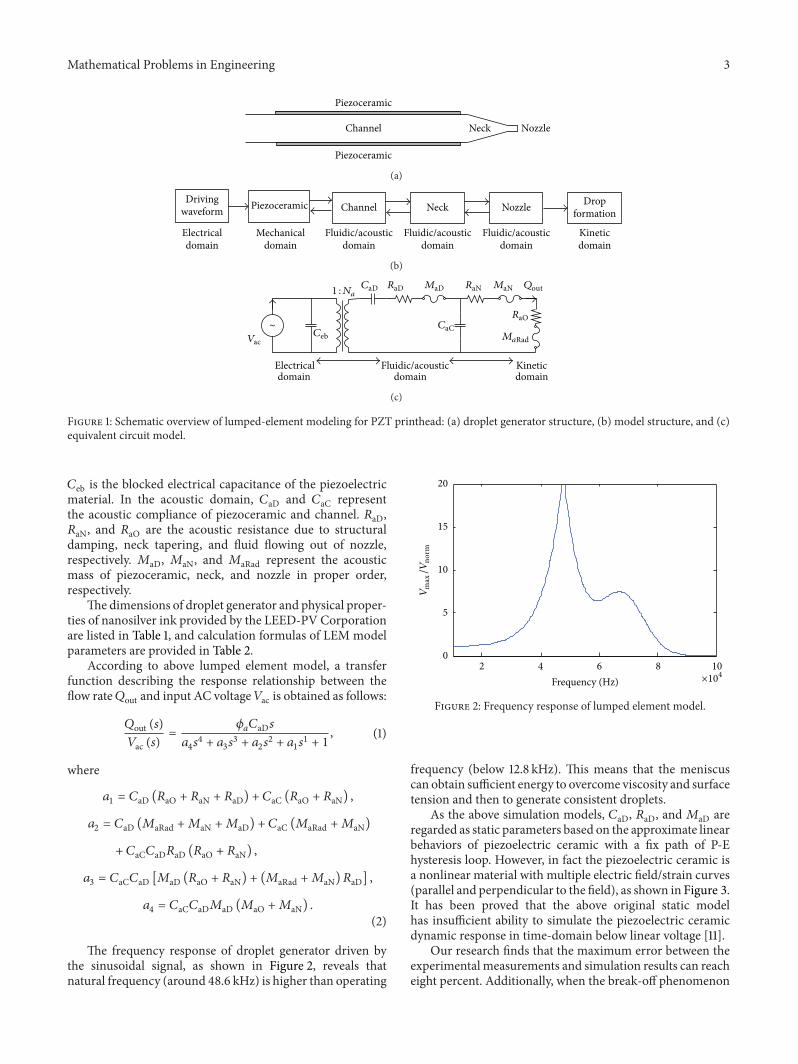
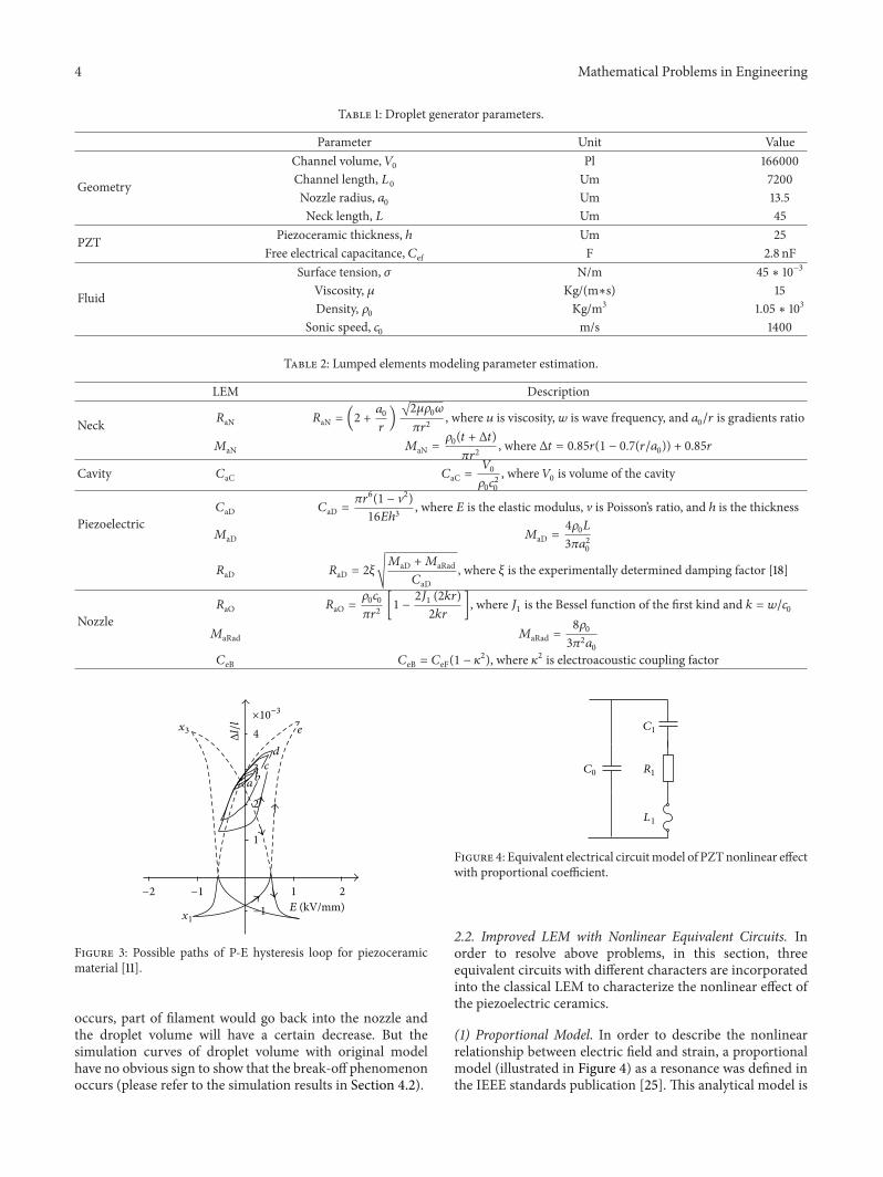
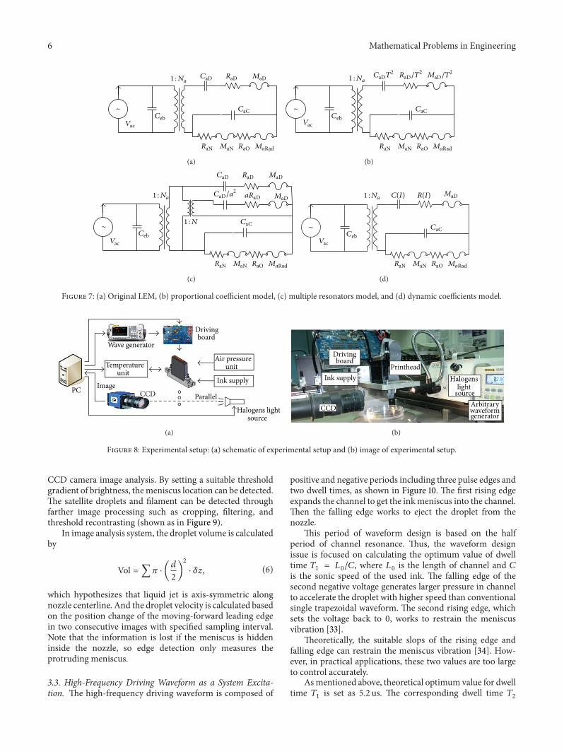
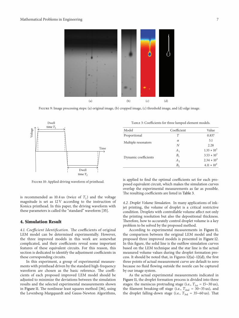
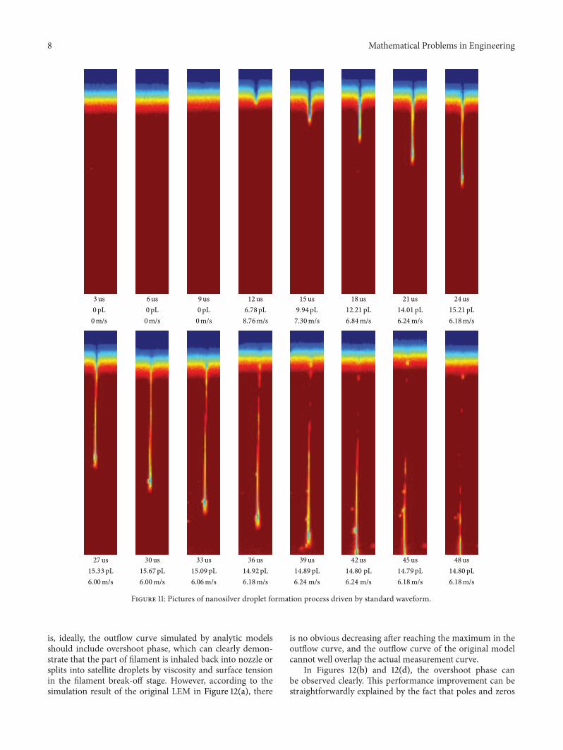
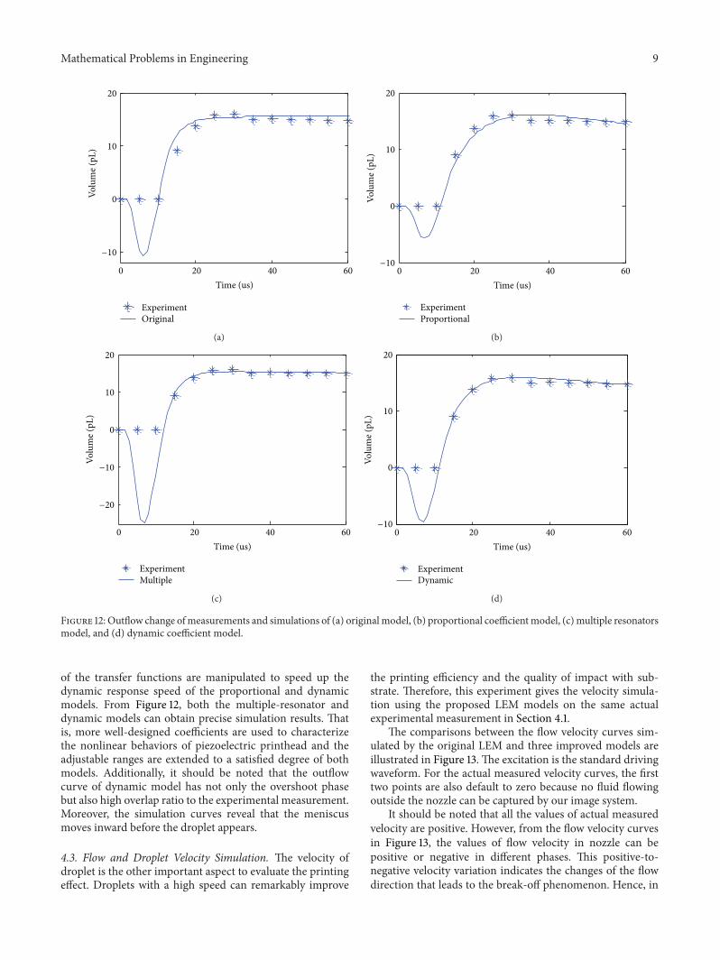
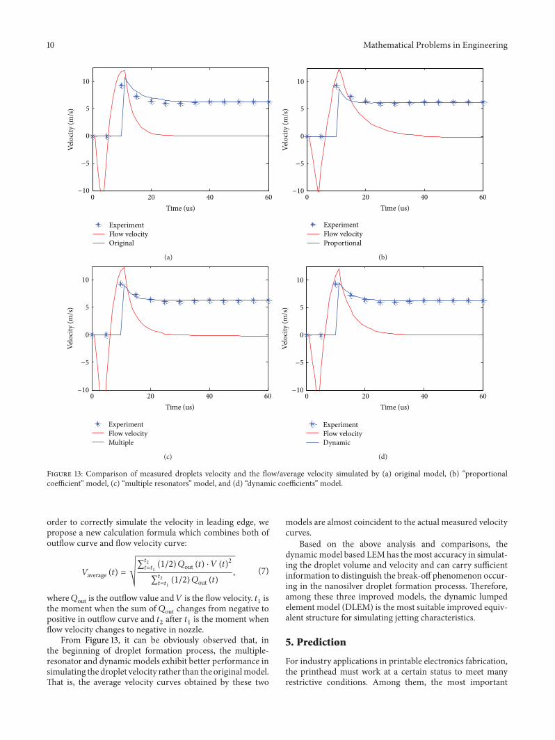
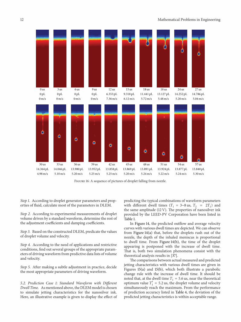
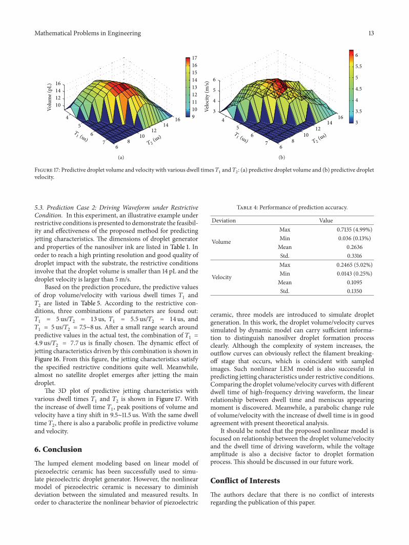