
Research Article A Fault-Tolerant Multiple Sensor Fusion ...
13
Research Article A Fault-Tolerant Multiple Sensor Fusion Approach Applied to UAV Attitude Estimation Yu Gu, 1 Jason N. Gross, 1 Matthew B. Rhudy, 2 and Kyle Lassak 1 1 Department of Mechanical and Aerospace Engineering (MAE) at West Virginia University (WVU), Morgantown, WV 26506, USA 2 Division of Engineering, Pennsylvania State University, Reading, PA 19610, USA Correspondence should be addressed to Yu Gu; [email protected] Received 1 October 2015; Revised 15 January 2016; Accepted 27 January 2016 Academic Editor: Enrico C. Lorenzini Copyright © 2016 Yu Gu et al. is is an open access article distributed under the Creative Commons Attribution License, which permits unrestricted use, distribution, and reproduction in any medium, provided the original work is properly cited. A novel sensor fusion design framework is presented with the objective of improving the overall multisensor measurement system performance and achieving graceful degradation following individual sensor failures. e Unscented Information Filter (UIF) is used to provide a useful tool for combining information from multiple sources. A two-step off-line and on-line calibration procedure refines sensor error models and improves the measurement performance. A Fault Detection and Identification (FDI) scheme crosschecks sensor measurements and simultaneously monitors sensor biases. Low-quality or faulty sensor readings are then rejected from the final sensor fusion process. e attitude estimation problem is used as a case study for the multiple sensor fusion algorithm design, with information provided by a set of low-cost rate gyroscopes, accelerometers, magnetometers, and a single-frequency GPS receiver’s position and velocity solution. Flight data collected with an Unmanned Aerial Vehicle (UAV) research test bed verifies the sensor fusion, adaptation, and fault-tolerance capabilities of the designed sensor fusion algorithm. 1. Introduction Sensing through a fusion of diverse but interrelated sensory data could reveal information that is difficult to measure directly. Having complementary and multiperspective view- points also allows for real-time evaluation of individual sensors’ performance and limitations, further enabling a reconfiguration of the measurement system if necessary. From this perspective, sensor fusion can be viewed as a process of refining internal models of both the measured phe- nomenon (for improved performance) and the measurement system (for improved reliability) through processing a hetero- geneous set of sensory data. Within this context, a three-step sensor fusion design framework is presented in this paper. Step 1. Combine sensory data from diverse and redundant sources to derive a fused solution that is difficult to measure directly and/or has better quality than the output of each participating sensor. Step 2. Refine sensor error models with feedback from the sensor fusion algorithm. Step 3. Reconfigure the measurement system to achieve performance enhancement under nominal conditions and graceful degradation following sensor failures. Step 1 reflects a “traditional” view of sensor fusion. Many existing approaches are model based, which relies on a set of mathematical models to relate individual measurements to the fused solution. ese models represent a priori knowledge of the system to be measured and are based either on known relationships or on assumptions and heuristics. For numeri- cal sensory data, a Bayesian filter [1, 2] is oſten used to derive a fused solution. is solution can either be computed at a centralized location or distributed among sensor nodes [3–5]. Step 2 enables the measurement system to maintain an updated knowledge of its states. At the sensor level, redundant information sources provide references for crosschecking and Hindawi Publishing Corporation International Journal of Aerospace Engineering Volume 2016, Article ID 6217428, 12 pages http://dx.doi.org/10.1155/2016/6217428
Transcript of Research Article A Fault-Tolerant Multiple Sensor Fusion ...

Research ArticleA Fault-Tolerant Multiple Sensor Fusion Approach Applied toUAV Attitude Estimation
Yu Gu1 Jason N Gross1 Matthew B Rhudy2 and Kyle Lassak1
1Department of Mechanical and Aerospace Engineering (MAE) at West Virginia University (WVU)Morgantown WV 26506 USA2Division of Engineering Pennsylvania State University Reading PA 19610 USA
Correspondence should be addressed to Yu Gu yugumailwvuedu
Received 1 October 2015 Revised 15 January 2016 Accepted 27 January 2016
Academic Editor Enrico C Lorenzini
Copyright copy 2016 Yu Gu et al This is an open access article distributed under the Creative Commons Attribution License whichpermits unrestricted use distribution and reproduction in any medium provided the original work is properly cited
A novel sensor fusion design framework is presented with the objective of improving the overall multisensor measurement systemperformance and achieving graceful degradation following individual sensor failures The Unscented Information Filter (UIF)is used to provide a useful tool for combining information from multiple sources A two-step off-line and on-line calibrationprocedure refines sensor error models and improves the measurement performance A Fault Detection and Identification (FDI)scheme crosschecks sensor measurements and simultaneously monitors sensor biases Low-quality or faulty sensor readings arethen rejected from the final sensor fusion process The attitude estimation problem is used as a case study for the multiple sensorfusion algorithm design with information provided by a set of low-cost rate gyroscopes accelerometers magnetometers anda single-frequency GPS receiverrsquos position and velocity solution Flight data collected with an Unmanned Aerial Vehicle (UAV)research test bed verifies the sensor fusion adaptation and fault-tolerance capabilities of the designed sensor fusion algorithm
1 Introduction
Sensing through a fusion of diverse but interrelated sensorydata could reveal information that is difficult to measuredirectly Having complementary and multiperspective view-points also allows for real-time evaluation of individualsensorsrsquo performance and limitations further enabling areconfiguration of the measurement system if necessaryFrom this perspective sensor fusion can be viewed as aprocess of refining internalmodels of both themeasured phe-nomenon (for improved performance) and the measurementsystem (for improved reliability) throughprocessing a hetero-geneous set of sensory data Within this context a three-stepsensor fusion design framework is presented in this paper
Step 1 Combine sensory data from diverse and redundantsources to derive a fused solution that is difficult to measuredirectly andor has better quality than the output of eachparticipating sensor
Step 2 Refine sensor error models with feedback from thesensor fusion algorithm
Step 3 Reconfigure the measurement system to achieveperformance enhancement under nominal conditions andgraceful degradation following sensor failures
Step 1 reflects a ldquotraditionalrdquo view of sensor fusion Manyexisting approaches are model based which relies on a setof mathematical models to relate individual measurements tothe fused solutionThesemodels represent a priori knowledgeof the system to be measured and are based either on knownrelationships or on assumptions and heuristics For numeri-cal sensory data a Bayesian filter [1 2] is often used to derivea fused solution This solution can either be computed at acentralized location or distributed among sensor nodes [3ndash5]
Step 2 enables the measurement system to maintain anupdated knowledge of its states At the sensor level redundantinformation sources provide references for crosschecking and
Hindawi Publishing CorporationInternational Journal of Aerospace EngineeringVolume 2016 Article ID 6217428 12 pageshttpdxdoiorg10115520166217428
2 International Journal of Aerospace Engineering
calibrating individual sensors used within the measurementsystemThis extends the traditional off-line sensor calibration[6] process to an on-line process If a certain mathematicalstructure of the sensor model is assumed the dynamicsensor calibration reduces to a parameter identification [78] problem For example sensor bias or scaling factors areoften estimated along with other states within a sensor fusionalgorithm [9]
Step 3 integrates results from the first two levels tofurther improve the performance and robustness of themeasurement system in several aspects First the sensorerror models refined through the dynamic calibration pro-cess could improve the overall estimation performance andprovide indications of the health condition of each sensorSecond a comparison of sensory data collected from diversebut interrelated sources provides information for sensor FaultDetection Identification and Accommodation (FDIA) [1011] Finally the robustness of the measurement system couldbe improved by rejecting [4] low quality or faulty sensormeasurements from the measurement update
The goal of this paper is to demonstrate this three-step sensor fusion approach through a practical applica-tion to achieve reliable and accurate attitude estimationwith a low-cost Inertial Measurement Unit (IMU) GlobalPositioning System (GPS) receiver and triaxial magnetome-ters As an important navigation problem the 3D attitudefor Unmanned Aerial Vehicles (UAVs) mobile robots andmobile devices were estimated using a variety of informationsourcesThis includes but not limited to dead reckoning withrate gyroscopes sensing of earthrsquos gravity [12] and magneticvectors [13] angular position of celestial objects [14] horizonline [15] terrain shape [16] optical flow [17] and known radiosources [18] such as GPS [19] and cellular network [20] Theselection of IMU GPS and magnetometers as the primarysensors for this study was mainly due to their widespreadavailability and popularity in various platforms as well asthe low-computational requirement of implementing thesesensors when compared with methods such as computervision or Lidar based mapping
The novel contributions of this effort include the follow-ing
(1) A systematic design approach that integrates bothsensor calibration and fault tolerance into a multiplesensor fusion system
(2) A FDI method based on information crosscheckingand sensor bias tracking
The performance of all presented algorithms is evaluatedwith flight datasets through processing of real flight datataken from an experimental UAV Portions of this paperincluding some figures and tables are contained within achapter of the second authorrsquos graduate thesis [21]
The rest of the paper is organized as follows Section 2introduces four different sensor fusion formulations for vehi-cle attitude estimation using Unscented Information Filter(UIF) as the nonlinear estimator The sensor calibrationprocess for refining sensor error models is described inSection 3 Section 4 presents the FDIA methods Section 5
discusses the experimental setup used in this studyThemainresults of this work are presented in Section 6 followed by aconclusion in Section 7
2 Fusion of GPS IMU and MagnetometerMeasurements
21 Coordinate Systems Two coordinate systems are usedthroughout this paper A local-level Cartesian navigationframe (119871) is defined with its origin 119874
119871 at an arbitrarypoint near the vehicle positive 119909
119871 axis pointing toward thegeographic north positive 119910
119871 axis pointing east and positive119911119871 axis pointing to the center of the earth A vehicle body-axescoordinate system (119861) is defined with its origin at vehiclersquosCenter of Gravity (CG) with positive 119909
119861 pointing forward ofthe vehicle positive 119910
119861 axis toward right and positive 119911119861 axis
toward the bottom of the vehicle Each sensor on-board ofthe UAV is assumed are assumed to be aligned with the bodyaxes and to be located relatively close to each other (ie a verysmall lever arm between the GPS and IMU)
The rotation of measurements between the two coordi-nate systems is calculated through the use of three attitude(Euler) angles yaw (120595) pitch (120579) and roll (120601) For examplethe earthrsquos gravity vector and centrifugal acceleration due tothe earthrsquos rotation (ie sensed ldquoplumb-bobrdquo acceleration)components in the vehicle body axis are found by assumingthat it is parallel to the navigation frame 119911
119871 axis and rotatingwith a Direction Cosine Matrix (DCM)
[[[
[
119892119861
119909
119892119861
119910
119892119861
119911
]]]
]
= DCM (120601 120579 120595)119879sdot[[
[
0
0
119892
]]
]
(1)
that is defined by the body-axis attitude
DCM (120601 120579 120595)
=[[
[
119888120595119888120579 minus119904120595119888120601 + 119888120595119904120579119904120601 119904120595119904120601 + 119888120595119904120579119888120601
119904120595119888120579 119888120595119888120601 + 119904120595119904120579119904120601 minus119888120595119904120601 + 119904120595119904120579119888120601
minus119904120579 119888120579119904120601 119888120579119888120601
]]
]
(2)
where ldquo119904rdquo and ldquo119888rdquo are abbreviated sine and cosine functionsrespectively
22 Information Sources Two types of information sourcesare generally available for estimating a vehiclersquos attitudeangles (1) the time-integration of rate gyroscope measure-ments (2) the measurement of external vector fields of well-known directions With readings from a set of 3-axis strap-down rate gyroscopes the attitude angles are computed witha set of attitude kinematic equations [22]
= 119901 + 119902 sin120601 tan 120579 + 119903 cos120601 tan 120579
= 119902 cos120601 minus 119903 sin120601
= (119902 sin120601 + 119903 cos120601) sec 120579
(3)
International Journal of Aerospace Engineering 3
where 119901 119902 and 119903 are the roll rate pitch rate and yawrate measured in the body axis respectively This attitudesolution will diverge over the time due to the accumulationof rate gyroscope biases during the integration process Fortypical low-cost microelectromechanical systems- (MEMS-)based gyroscopes the uncorrected attitude solutions are notdirectly usable after a short period of time
A standard approach for controlling the attitude errorgrowth is to regulate it with nondrifting information sourcessuch as the known direction of an external vector fieldExamples of commonly used aiding information include theearthrsquos gravity vector [12] the earthrsquos magnetic vector [13]GPS [19] cellular network [20] celestial map [14] horizonline [15] terrain map [16] computer vision [17] and knownradio sources [18] From this list earthrsquos gravity andmagneticvector fields are often the easiest to measure and thereforeare discussed in detail in this paper Four sensor fusionformulations are presented in the rest of this section toshow that a fusion of any combination of GPS IMU andmagnetometers is capable of providing nondrifting Eulerangle estimates
23 Sensor Fusion Formulation 1 GPSIMU The attitudeof a stationary vehicle can be directly solved from (1) usingmeasurements from a set of 3-axis accelerometers For amov-ing vehicle the accelerometers measure both the accelerationdue to gravity and the vehiclersquos acceleration in the inertialframe To isolate the gravity vector from inertial accelerationa GPS receiverrsquos velocity solution provides an independentobservation of the vehiclersquos inertial acceleration in the localCartesian coordinates Since the GPS will not sense theearthrsquos gravity the relationship between accelerometer mea-surements a119861 and GPS velocity measurements V119871 can bedescribed by
[[[[
[
119871
119909
119871
119910
119871
119911
]]]]
]GPS
= DCM (120601 120579 120595) sdot
[[[
[
119886119861
119909
119886119861
119910
119886119861
119911
]]]
]IMU
+[[
[
0
0
119892
]]
]
(4)
Using the heading information provided by the GPS
120595 = tanminus1(119881119871
119910
119881119871119909
) (5)
Equation (4) can be explicitly solved to calculate Euler angles[12] However a better approach exists with the use of thestationary gravity vector to regulate the INS integrationerror with a recursive estimator Within this formulationthe state input and measurement vectors are respectivelyx = [120601 120579 120595]
119879 u = [119901 119902 119903]119879 and z = a119871 = [119886
119871
119909119886119871
119910119886119871
119911]119879
The nonlinear continuous-time state transition equations x =
f119888(x uw) are directly based on (3)
[[[
[
]]]
]
=
[[[
[
(119901 + 119908119901) + (119902 + 119908
119902) sin120601 tan 120579 + (119903 + 119908
119903) cos120601 tan 120579
(119902 + 119908119902) cos120601 minus (119903 + 119908
119903) sin120601
((119902 + 119908119902) sin120601 + (119903 + 119908
119903) cos120601) sec 120579
]]]
]
(6)
where 119908119901119902119903
are the noises associated with the correspond-ing rate gyroscope measurements which are assumed tobe zero mean white Gaussian w
1= [119908119901 119908
119902119908119903]119879
asymp
119873(0Q1) Note that 119908
119901119902119903are implemented as nonadditive
input noises instead of modeling process noise additive onthe state estimates which is commonly used in Kalman filterformulations
The continuousobservation equations z = h119888(x k) arealso nonlinear and are modeled by
[[[[
[
119871
119909+ V119892119909
119871
119910+ V119892119910
119871
119911+ V119892119911
]]]]
]GPS
= DCM (120601 120579 120595) sdot
[[[
[
119886119861
119909+ V119886119909
119886119861
119910+ V119886119910
119886119861
119911+ V119886119911
]]]
]IMU
+[[
[
0
0
119892
]]
]
(7)
where V119892119909119892119910119892119911
are the noises assumed to be white for theGPS estimated accelerations and V
119886119909119886119910119886119911are noises asso-
ciated with the accelerometer measurements with v1
=
[V119892119909 V119892119910
V119892119911
V119886119909
V119886119910
V119886119911]119879
asymp 119873(0R1)
24 Sensor Fusion Formulation 2 IMUMagnetometersThe gravity vector used in Formulation 1 can be directlysubstituted with the Earthrsquos magnetic vector in regulatingthe growth of the rate gyroscope integration error For thisformulation the state input and measurement vectors aregiven respectively by x = [120601 120579 120595]
119879 u = [119901 119902 119903]119879 and
z = [119872119861
119909119872119861
119910119872119861
119911]119879
where 119872119861
119909119910119911are the magnetometer
measurements The state transition equations are the same asin (6) and the nonlinear observation equations are given by
[[[
[
119872119861
119909+ V119872119909
119872119861
119910+ V119872119910
119872119861
119911+ V119872119911
]]]
]
= DCM (120601 120579 120595)119879sdot
[[[
[
119872119890119871
119909
119872119890119871
119910
119872119890119871
119911
]]]
]
(8)
where 119872119890119871
119909119910119911is the local magnetic vector determined with
National Oceanic and Atmospheric AdministrationrsquosGeomagnetic Online Calculator [23] and v
2=
[V119872119909 V119872119910
V119872119911]119879
asymp 119873(0R2) are the noises associated
with the magnetometer measurements which are assumedto be zero mean white and Gaussian An appealing feature
4 International Journal of Aerospace Engineering
for the IMUmagnetometers formulation is that it canoperate indoors or within other GPS-denied environmentsHowever the local magnetic field can be distorted by theexistence of ferromagnetic materials in the close vicinityaffecting the attitude estimation performance A solution tothis problem is discussed in Section 3
25 Sensor Fusion Formulation 3 GPSMagnetometers Thebody-axis magnetic field measurements coupled with GPSheading also provide adequate information for Euler angleestimation at most places on earth that are not near themagnetic poles In this formulation the state input andmeasurement vectors are respectively x = [120601 120579]
119879 u =
[0 0]119879 and z = [119872
119861
119909119872119861
119910119872119861
119911]119879
Since the rate gyroscopemeasurements are not available in this case the state transi-tion equations are simply defined as follows
[
] = [
0
0] + w
2 (9)
where the unknowns 120601 and 120579 are assumed to be perturbedwith white noises w
2asymp 119873(0Q
2) The observation equations
are the same as in (8) where 120595 is calculated with (5) Theobservation equations could also be augmented with (7) toincorporate additional gravity vector constraints during themeasurement update The benefit of this formulation is thatit provides an independent attitude estimate without the rategyroscopes therefore this approach would not cause stabilityissues [24] in control systems that rely on rate gyroscopes forinner-loop feedback
26 Sensor Fusion Formulation 4 GPSIMUMag So farcombinations of any two sensors from the set of GPS IMUand magnetometers have been used for attitude estimationParticularly the differences between Formulations 1 and2 are only present in the observation equations Combin-ing the two sets of observation equations could lead to atighter regulation of the error growth in the strap-down INSequations In fact any measureable external vector field ofknown direction could be added to the observation equa-tions in a similar fashion For the GPSIMUmagnetometersformulation the state input and measurement vectors arerespectively x = [120601 120579 120595]
119879 u = [119901 119902 119903]119879 and z =
[119886119871
119909119886119871
119910119886119871
119911119872119861
119909119872119861
119910119872119861
119911]119879
The state transition equationsare the same as in (6) and the observation equations aresimply a combination of (7) and (8)
27 Unscented Information Filter An information filterapproach [5] is used for the fusion of multiple sensormeasurementsThemain advantage of using the informationfilter instead of Kalman filter is that the information updatecan be expressed as a sum
I119896|119896
= I119896|119896minus1
+
119873
sum
119895=1
I119895119896
i119896|119896
= i119896|119896minus1
+
119873
sum
119895=1
i119895119896
(10)
where I119896|119896minus1
is the predicted information matrix i119896|119896minus1
isthe predicted information state vector and I
119895119896 i119895119896
are themeasurement information matrix and information vectorrespectively associated with the 119895th measurement out ofa total of 119873 independent measurements This simple rela-tionship in information update creates a suitable frameworkfor addingremoving sensors and handling unsynchronizedmeasurement updates within a multisensor fusion system
The state estimation problems presented in Formulations1ndash4 are solved with an Unscented Information Filter (UIF)[3]TheUIF uses the same predictionmodel as an UnscentedKalman Filter (UKF) [25 26] to calculate the predicted errorcovariance matrix P
119896|119896minus1 and state estimation x
119896|119896minus1 The
predicted information matrix I119896|119896minus1
and predicted informa-tion state vector i
119896|119896minus1 are simply defined as follows
I119896|119896minus1
= Pminus1119896|119896minus1
i119896|119896minus1
= Pminus1119896|119896minus1
x119896|119896minus1
(11)
For the measurement update the nonlinear observa-tion equation for each independent measurement z
119895119896=
h119895(x119896|119896minus1
k119895119896
) is locally linearized with a statistical linearregression method [27]
z119895119896
asymp [Hx119895119896
Hk119895119896]⏟⏟⏟⏟⏟⏟⏟⏟⏟⏟⏟⏟⏟⏟⏟⏟⏟⏟⏟⏟⏟⏟⏟⏟⏟
H119895119896
[
x119896|119896minus1
k119895119896
]
⏟⏟⏟⏟⏟⏟⏟⏟⏟⏟⏟⏟⏟⏟⏟
x119886119896|119896minus1
+ b119895119896 (12)
that minimizes the sum of squared errors e119895119894
= 120594119894
119895119896minus
(H119895119896120594119894
119895119896|119896minus1+ b119895119896
)
H119895119896
b119895119896
= argminHb
2119871
sum
119894=0
e119879119895119894e119895119894 (13)
where H119895119896
= P119879119909119896119911119895119896
P119886119896|119896minus1
minus1 and b119895119896
= z119895119896
minus H119895119896x119886119896|119896minus1
Themean and covariance of e
119895are given by
e119895= 0
P119895119890119890
= P119911119895119896119911119895119896
minus H119895119896P119886119896|119896minus1
H119879119895119896
(14)
The measurement information matrix I119895119896
and informa-tion vector i
119895119896for the 119895th measurement [3] can then be
provided by
i119895119896
= Hx119879119895119896Rminus1119895119896
(z119895119896
minus b119895119896
)
I119895119896
= Hx119879119895119896Rminus1119895119896Hx119895119896
(15)
where R119895119896
is the covariance matrix for the sum of thelinearized actual observation noise R
119895and the linearization
noise
R119895119896
= Hz119895119896R119895Hz119879119895119896
+ P119895119890119890
= P119911119895119896119911119895119896
minus Hx119895119896P119896|119896minus1
Hx119879119895119896
(16)
The procedure for deriving (14)ndash(16) is outlined in [3]
International Journal of Aerospace Engineering 5
Following the information update equations (10) with allthe measurements during each time frame the estimatedposterior covariancematrix and state vector can be recoveredusing
P119896|119896
= Iminus1119896|119896
x119896|119896
= P119896|119896i119896|119896
(17)
3 Sensor Calibration
The existence of redundant information from differentsources provides an opportunity for calibrating each individ-ual sensor within the measurement system The calibrationprocess may be performed off-line [6] on-line [7 28] orusing a combination of the two The latter approach isused in this paper where a batch off-line calibration is firstperformed for the 3-axis magnetometers which then providethe initial condition for the recursive on-line calibrationThisprocedure has several advantages
(1) The off-line calibration process is less restricted by theavailability of computational resources therefore alarge set of calibration parameters can be evaluatedAdditionally the off-line calibration can be per-formed through comparing with temporary sensorsof higher quality (to be removed before the operation)and data from deliberately performed maneuvers
(2) The off-line calibrated sensor parameters provide apriori knowledge of the sensor error model The on-line calibration then starts from off-line calibratedparameters minimizing the impact of the transientresponse based on better initial estimates
(3) The on-line calibration provides the capability fordealing with time varying parameters
(4) The on-line calibrated parameters can be restrictedwithin a set of prespecified bounds and the calibrationcan be turned off or revert to the off-line values in theevent of unstable conditions
The concept of this 2-step calibration process is similarto the adaptive augmentation of a baseline controller [29] incontrol theoryWithin this effort the magnetometers are firstcalibrated off-line followed by an on-line estimation of ninesensor biases associatedwith rate gyroscopes accelerometersand magnetometers
31 Magnetometer Error Model The magnetometer readingsof earthrsquos magnetic field are often distorted by the existence offerromagneticmaterials in the local area as well as the imper-fection in the measurement system itself The calibration ofthe magnetometer is a well-studied problem in the literature[27 28 30] However most calibration research in the pastwas performed off-line due to a lack of reference informationduring the vehicle operation
Without a loss of generality the 3-axis magnetometercalibration process is formulated as a nonlinear parameteridentification (PID) problem
[[[[
[
119861
119909
119861
119910
119861
119911
]]]]
]
= DCM (119877119872120601
119877119872120579
119877119872120595
)119879
⏟⏟⏟⏟⏟⏟⏟⏟⏟⏟⏟⏟⏟⏟⏟⏟⏟⏟⏟⏟⏟⏟⏟⏟⏟⏟⏟⏟⏟⏟⏟⏟⏟⏟⏟⏟⏟⏟⏟⏟⏟⏟⏟⏟⏟⏟⏟
R119872
sdot[[
[
119878119872119909
0 0
0 119878119872119910
0
0 0 119878119872119911
]]
]⏟⏟⏟⏟⏟⏟⏟⏟⏟⏟⏟⏟⏟⏟⏟⏟⏟⏟⏟⏟⏟⏟⏟⏟⏟⏟⏟⏟⏟⏟⏟⏟⏟
S119872
sdot
[[[
[
119872119861
119909
119872119861
119910
119872119861
119911
]]]
]
minus[[
[
119887119872119909
119887119872119910
119887119872119911
]]
]⏟⏟⏟⏟⏟⏟⏟⏟⏟⏟⏟⏟⏟
b119872
(18)
where 119861
119909119910119911are the calibrated magnetometer measure-
ments R119872
is a rotation matrix parameterized by the threerotation angles 119877
119872120601 119877119872120579
and 119877119872120595
S119872is a diagonal scaling
matrix and b119872is a bias vector The nine parameters
Θ119872
= [119877119872120601 119877119872120579
119877119872120595
119878119872119909
119878119872119910
119878119872119911
119887119872119909
119887119872119910
119887119872119911]119879
(19)
to be estimated capture all of the soft iron effects hard ironeffects sensor nonorthogonality bias and scaling factor [27]
32 Magnetometer Off-Line Calibration The off-line calibra-tion process starts with the creation of a set of reference sig-nals to be compared with the actual magnetometer measure-ments The reference is created by rotating the known earthrsquosmagnetic vectorM119890
119871 from the local Cartesian coordinates tothe vehiclersquos body axisM119890
119861
[[[
[
119872119890119861
119909
119872119890119861
119910
119872119890119861
119911
]]]
]
= DCM (120601 120579 120595)119879sdot
[[[
[
119872119890119871
119909
119872119890119871
119910
119872119890119871
119911
]]]
]
(20)
where the Euler angles are provided by a GPSIMU sensorfusion algorithm discussed earlier A set of estimated calibra-tion parameters Θ
119872is then acquired through minimizing a
cost function which spans over an entire set of flight datausing a quasi-Newton method
119869 = sum[(119861
119909minus 119872119890119861
119909)
2
+ (119861
119910minus 119872119890119861
119910)
2
+ (119861
119910minus 119872119890119861
119910)
2
]
Θ119872
= argminΘ119872isin119877
9
(119869)
(21)
The off-line calibration problem can also be solved with amaximum likelihood method similar to the one discussed in[27]
6 International Journal of Aerospace Engineering
33 Mag Gyro and Accelerometer On-Line Calibration Theon-line calibration process is performed by augmenting thesensor fusion Formulation 4with nine additional bias statesb = [119887119866119901 119887
119866119902119887119866119903
119887119860119909
119887119860119910
119887119860119911
119887119872119909
119887119872119910
119887119872119911]119879 one for
each magnetometer rate gyroscope and accelerometer Inthis way the attitude state estimation and sensor error modelparameter identification [8] are performed simultaneouslyDuring the state prediction stage the state transition equa-tions described in (6) are used for attitude states withthe exception that the estimated rate gyroscope biases aresubtracted from the raw IMUmeasurements
u = [119901 minus 119866119901
119902 minus 119866119902
119903 minus 119866119903
]119879
(22)
The dynamics of the nine bias states are modeled as randomwalk using
b = 0 + w3 (23)
where the bias states are only assumed to be perturbed withwhite noisesw
3asymp 119873(0Q
3)The initial conditions for the bias
states are set to be
b0= [0 0 0 0 0 0
119872119909119887119872119910
119872119911
]119879
(24)
where 119887119872119909119872119910119872119911
are off-line calibrated magnetometer biasvalues
The nonlinear observation equations are derived from (7)and (8) with added bias terms on the accelerometer mea-surements as well as the rotated and scaled magnetometermeasurements
[[[[
[
119871
119909+ V119892119909
119871
119910+ V119892119910
119871
119911+ V119892119911
]]]]
]GPS
= DCM (120601 120579 120595)
sdot
[[[
[
119886119861
119909minus 119887119860119909
+ V119886119909
119886119861
119910minus 119887119860119910
+ V119886119910
119886119861
119911minus 119860119911
+ V119886119911
]]]
]IMU
+[[
[
0
0
119892
]]
]
DCM (119872120601
119872120579
119872120595
)119879
sdot
[[[
[
119872119909
0 0
0 119872119910
0
0 0 119872119911
]]]
]
sdot
[[[
[
119872119861
119909+ V119872119909
119872119861
119910+ V119872119910
119872119861
119911+ V119872119911
]]]
]
minus
[[[
[
119872119909
119872119910
119872119911
]]]
]
= DCM (120601 120579 120595)119879
sdot
[[[
[
119872119890119871
119909
119872119890119871
119910
119872119890119871
119911
]]]
]
(25)
where R119872
and S119872
are the rotation and scaling matricesacquired from the off-line magnetometer calibration
4 Fault Detection Identification andAccommodation
The sensor FDIA is achieved through two independentapproaches information crosschecking and sensor biastracking The first approach detects discrepancies among allinformation sources to identify outliers which could be dueto temporary low-quality measurements or abrupt sensorfailures The second method allows detection and tracking ofldquosoftrdquo sensor failures that slowly develop over time
In our information crosschecking approach it is impor-tant to mention that under nominal conditions we assumethat each independent information source can observe validstate estimates and that the optimal state estimate wouldbe the result of fusing all sources Therefore because wehave multiple redundant information sources the goal isto identify outlier estimates and exclude their associatedinformation sources from the state estimate altogether Agraphical representation of the information crosscheckingapproach is shown in Figure 1
In Figure 1 first multiple Kalman updated statesand error-covariance estimates (or equivalently informationmatrices and vectors) are derived using the independentsources of information available In general (S
119896 I119896 i119896) are
available at each time step 119896 where S119896is a set of119873+1 indepen-
dent information sources from either prediction or a sensormeasurement and I
119896 i119896are sets of the associated Fisher
information matrices and vectors Next to identify potentialoutlier information sources the Mahalanobis distance [31]is used to evaluate the ldquoclosenessrdquo between pairwise sets ofestimates For example to determine if the 119904th informationsource is consistent with the 119903th information source weevaluate
P119904119896
= Iminus1119904119896
x119904119896
= P119904119896i119904119896
P119903119896
= Iminus1119903119896
x119903119896
= P119903119896i119903119896
(26)
in order to calculate the square of the Mahalanobis distancebetween them Consider
119865119904|119903119896
= (x119904119896
minus x119903119896
)119879(P119904119896
+ P119903119896
)minus1
(x119904119896
minus x119903119896
) (27)
We chose to use Mahalanobis distance because it is an intu-itive metric that indicates the statistical agreement betweenstate estimates Additionally it takes into consideration esti-mated error-covariance and is extensible to high dimensionstate-spaces
After considering all unique pairs of estimates from indi-vidual information sources a total of 119873 + 1 unique values areavailable to base our fault detection and identification uponHowever these values represent the ldquoclosenessrdquo betweenestimate pairs which is not the most convenient for thegoal of identifying individual faulty information sources Inparticular it would be more beneficial if we could evaluatehow well each individual information source agrees with
International Journal of Aerospace Engineering 7
Gyroscope estimates
Magnetic estimates
Gravity estimates
Threshold
Threshold
Threshold
rarrFM|G
rarrFM|R
rarrFM
rarrFG|M
rarrFG|R
rarrFG
rarrFR
rarrFR|G
rarrFR|M
rarrFM
rarrFG
rarrFR
xMk|kYMk|k xGk|kY
Gk|k
xk|kminus1Yk|kminus1
Figure 1 Fault Detection Identification and Accommodation approach
all other sources in a single metric To accomplish this weemploy a simple vector in addition to combining the squaredMahalanobis distance values from each information sourcewith respect to all others The sum then represents how wella particular information source agrees with all others Asan example for information source 119904 we define all the unitvectors to other information sources
u119904|119894
=(e119904119896
minus e119894119896)
1003817100381710038171003817e119904119896 minus e119894119896
1003817100381710038171003817
(119894 = 1 119873 119894 = 119904) (28)
Then using the values calculated in (27) we use their inversevalues to scale each unit vector sumwith vector addition andfind the resultant magnitude The use of the inverse of thesquared Mahalanobis distance is analogous to inverse squarelaws that govern power loss The resultant e
119904119896is a sum of a
total of119873minus1 vectors associated with e119904119896and each component
of E119896
F119904=
119873
sum
119894=1
F119904|119894 (119894 = 119904) (29)
Finally the magnitude of the detection vector F119904 provides
a scalar assessment of the agreement between e119904119896and other
estimates at the same time If F119904 is less than a prespecified
threshold Ω119904 that is set based upon empirical tuning a
failure is declared for the sensor associated with e119904119896
For the attitude estimation problem described in thispaper three information sources are available at time step119896 based on the posterior estimates from the previous step(I119896minus1|119896minus1
i119896minus1|119896minus1
) (1) rate gyroscopes based a priori estimates
(I119896|119896minus1
i119896|119896minus1
) (2) the posterior estimates (I119866119896|119896
i119866119896|119896) updated
with the gravity vector information (3) the posterior esti-mates (I119872
119896|119896 i119872119896|119896) updated with the magnetic vector informa-
tion To ensure the independence of the three estimates thecalculation of (I119866
119896|119896 i119866119896|119896) and (I119872
119896|119896 i119872119896|119896) are based on a random
walk assumption only instead of using the rate gyroscopemeasurements during the prediction step
x = 0 + w4 (30)
where w4asymp 119873(0Q
4) are white noises
To complement the information crosschecking approachthe sensor bias tracking method monitors the bias statesestimated by the on-line calibration scheme Under nominalconditions all sensor biases should be bounded within aprespecified envelope e The size of e can be determinedbased on a statistical evaluation of data collected in the past aswell as common sensor error specifications such as the biasinstability for the case of accelerometers and rate gyroscopesDuring the operation if a sensor bias grows outside of e ananomaly warning for this particular sensor is declared andno additional action is taken If the bias continues to growbeyond 120572sdot e where 120572 gt 1 is a prespecified threshold value asensor failure status is declared Under this condition the biasstates that are directly correlated or closely coupled with thefaulty sensor are capped at or below their current value andthe associated error covariance matrix is scaled at each timestep to represent an increasingly uncertain knowledge of thebias states
P119891119896|119896minus1
= 120573 sdot P119891119896|119896minus1
(31)
8 International Journal of Aerospace Engineering
Selection
Information
States
Update
Update
Prediction
Random walk
Measurement
State transition
FDI
Informationstream
Prediction
Measurement number N
Measurement number j
Measurement number 1
z1k
i I1k(p r)
i INk(p r)
ΣyYk|k xPk|k
Bias states xBk = k + 1
xPkminus1|kminus1
yYk|kminus1 (p prediction)
yYk|kminus1 (r random walk)
uk
xk = xkminus1 + w
Figure 2 Overall sensor fusion algorithm architecture
IMU and magnetometers
GPS antenna and receiver
Mechanical vertical gyro
Figure 3 WVU YF-22 research aircraft and relevant sensors
where 120573 gt 1 is empirically selected to be 1005 in thisimplementation
Once a failure is declared with either FDI approach faultaccommodation is based on a simple concept with the avail-ability of redundant information and with the informationupdate being a sum the UIF has the freedom of rejectingany sensor measurement it considers a fault or of lower-quality This approach allows the sensor fusion algorithm tobe conservative and only uses the best information for stateestimation A block diagram for the UIF based fault-tolerantmultiple sensor fusion algorithm is shown in Figure 2
5 Experimental Setup
The sensor fusion algorithms outlined in the previous sec-tions are evaluated with the actual flight data from YF-22unmanned research aircraft [32] developed at West VirginiaUniversity The vehicle shown in Figure 3 is approximately24m long with a 2m wing span and has a take-off weightof approximately 225 Kg The aircraft is powered with aminiature turbine that provides 125N of static thrust Thecruise speed for the aircraft is approximately 40ms
The aircraft instrumentation [33] includes three sensorsdirectly relevant to this study An Analog Devices ADIS-16405reg tri-axis inertial sensor with magnetometers is usedto provide a 14-bit digital output of 3-axis accelerationangular rate and magnetic field measurements with a fullscale range of plusmn18 g plusmn150∘s and plusmn25 Gauss respectivelyThe manufacturer reported 1 minus 120590 initial bias errors for theaccelerometers rate gyroscopes and magnetometers thatare plusmn50mg plusmn3∘s and plusmn4mGauss respectively A NovatelOEM4reg GPS receiver provides an estimate of the aircraft3D position and velocity in the Earth-Centered Earth-Fixed(ECEF) coordinate system independent of the inertial andmagnetic sensors which is transformed into a local Cartesiancoordinate system The manufacturer reported GPS positionand velocity accuracies are 18 meter Circular Error Probable(CEP) and 003ms Root Mean Square (RMS) respectivelyA Goodrich VG34reg mechanical vertical gyroscope is used toprovide independent pitch and roll angle measurements andis used as the ldquotruth datardquo for this sensor fusion study TheVG34 has a plusmn90∘ measurement range on the roll axis anda plusmn60∘ range on the pitch axis and is sampled with 16-bitresolutionThe VG34 has a self-erection system and reportedaccuracy of within 025∘ of true vertical
International Journal of Aerospace Engineering 9
Table 1 Statistics of attitude estimation algorithms
Formulation 119864 (1003816100381610038161003816120601err
1003816100381610038161003816) 120590 (120601err) 119864 (1003816100381610038161003816120579err
1003816100381610038161003816) 120590 (120579err)
GPSIMU 2990 1671 1590 1865GPSIMU + 6 bias states 1516 1524 1558 1700GPSMag (Off-L Cal) 1726 2008 2315 2195IMUMag (Off-L Cal) 1581 1959 2299 2769GPSIMUMag (Raw) 8061 3219 5276 2279GPSIMUMag(Off-L Cal) 2026 1452 2415 2127
GPSIMUMag(Off-L + On-L Cal) 1598 1697 1417 1679
6 Results
The sensor fusion algorithms are validated using three setsof flight data The first set is used for magnetometer off-linecalibration A GPSIMU sensor fusion algorithm (Formula-tion 1) augmentedwith six rate gyroscope and accelerometerbias states is used to estimate the attitude angles requiredby the off-line magnetometer calibration algorithm Theremaining two sets of flight data collected from two differentdays were used to validate and compare different sensorfusion algorithm performance Table 1 lists the estimationperformance of eight sensor fusion algorithms in terms ofmean absolute error and error standard deviation for pitchand roll angle estimates An average of two flights is usedin calculating the value of each entry The same stochasticnoise modeling assumptions of the GPS rate gyroscopeaccelerometer and magnetometer noises were used for eachformulation and no individual tuning was performed
Table 1 shows that each algorithm is able to provide apitch and roll estimate The GPSIMU and GPSMag for-mulations both have good performance but the IMUMagperforms poorly with off-line calibrated magnetometers Theperformance of IMUMag formulation is found to be highlysensitive to the quality of the calibration
The combination of all three sensors gives a good attitudeestimation performance once a set of off-line calibratedmagnetometer parameters are used The introduction of anon-line calibration scheme to the GPSIMUMag sensorfusion algorithm provides an additional enhancement of itsperformance Figure 4 shows a section of the flight withvertical gyroscope pitch measurements along with estimatesfrom the GPSIMUMag sensor fusion algorithm with rawmagnetometer readings off-line calibrated parameters and acombined off-line and on-line sensor calibration
The fault-tolerant aspect of the sensor fusion algorithmis validated with simulated sensor failures superimposed onthe actual flight data The performance of the sensor fusionalgorithm with and without FDI and fault accommodationschemes under nominal condition were first evaluated alongwith the estimation performance under a set of simple sensorfailure scenarios where the outputs of GPS rate gyroscopesor magnetometers were lost for the second half (50) of theflight Table 2 summarizes the results of this test
Table 2 Statistics of UIF-based fault tolerant attitude estimation
Operating condition 119864 (1003816100381610038161003816120601err
1003816100381610038161003816) 120590 (120601err) 119864 (1003816100381610038161003816120579err
1003816100381610038161003816) 120590 (120579err)
Nominal wo FDIA 1598 1697 1417 1679Nominal wFDIA 1585 1708 1360 1610GPS failure wFDIA 3566 5546 2205 3185Gyro failure wFDIA 1814 2211 1622 1821Mag failure wFDIA 1890 2111 1534 1892
UIF GPSIMUMag pitch estimation versus vertical gyroscope
Vertical gyroscopeRaw Mag
Off-line Mag calibration
505 510 515 520 525 530500Time (s)
Off-line + on-line calibration
minus15
minus10
minus5
0
5
10
15
20
Pitc
h an
gle (
deg
)
Figure 4 GPSIMUMag sensor fusion with raw off-line calibra-tion and a two-stage off-lineon-line calibration
An interesting observation is that the inclusion of theFDIA scheme slightly improves the overall performance ofthe sensor fusion algorithm even under nominal conditionswithout imposed sensor failures This is due to the fact thatthe FDIA scheme monitors the quality of each measurementand rejects information of lower qualityThis desirable featureis demonstrated in Figure 5 where four GPS data points wererejected by the sensor fusion algorithm during a half-secondsection of the flight
10 International Journal of Aerospace Engineering
Rejected GPS measurements
2796 2797 2798 2799 2802795Time (s)
GPS Y-axis velocity measurement
22
24
26
Vy
(ms
)
Roll estimation versus vertical gyroscope
Vertical gyroscopeSensor fusion with FDIASensor fusion without FDIA
2796 2797 2798 2799 2802795Time (s)
minus55
minus54
minus53
minus52
minus51
Roll
angl
e (de
g)
Figure 5 Rejection of low-quality GPSmeasurements by the sensorfusion algorithm
The ability of the sensor fusion algorithm to detectaccommodate and recover from different sensor failures isfurther demonstrated in Figure 6 where a series of sequen-tially imposed GPS rate gyroscope and magnetometer fail-ures are presented The force field based failure detectionsignals for each set of sensors are also shown in Figure 7 alongwith the respective detection threshold indicated as a dottedline
Figure 6 demonstrates an advantage of this informa-tion filter based fault accommodation method for faultaccommodationThe transition between nominal and failureconditions in terms of attitude estimation is smooth andseamless The estimation performance gracefully degradesafter a sensor failure and recovers after the failure is removed
In addition to large and abrupt sensor failures the abilityof the sensor fusion algorithm to handle slowly developingldquosoftrdquo failures is demonstrated in Figure 8 A random walkbias (with 120590 = 002 degsec) is added to the pitch rate sensormeasurements and the pitch rate bias state estimate is used forFDI The sensor fusion algorithm compensates for the ldquosoftrdquofailure through sensor calibration when the bias is small andthrough sensor rejection when it becomes large
7 Conclusions and Discussion
In this paper a general 3-step sensor fusion approach isproposed and is applied to a 3D attitude estimation prob-lem The validation results using sets of UAV flight datashow that having multiple redundant information sourcesallows for on-line calibration of individual sensors withinthe measurement system leading to both improved per-formance and improved understanding of sensor healthconditions especially under ldquosoftrdquo sensor failure conditions
Roll estimation with sensor failures
Sensor fusionVertical gyroscope
220 230 240 250 260 270 280 290 300 310210Time (s)
minus60
minus40
minus20
02040
Roll
angl
e (de
g)
Roll estimation error sensor failures
220 230 240 250 260 270 280 290 300 310210Time (s)
Gyro fail Mag fail GPS failminus10
minus5
0
5
10
Roll
erro
r (de
g)
Figure 6 Sensor fusion with no failure GPS failure rate gyroscopefailure and magnetometer failure
Rate gyroscope virtual force magnitude
Magnetometer virtual force magnitude
GPSAccel virtual force magnitude
220 230 240 250 260 270 280 290 300 310210Time (s)
220 230 240 250 260 270 280 290 300 310210Time (s)
220 230 240 250 260 270 280 290 300 310210Time (s)
log 1
0(F
R)
minus5
0
5
minus5
0
5
log 1
0(F
M)
minus10
0
10
log 1
0(F
G)
Figure 7 ldquoVirtual Force Fieldrdquo based failure detection signal
Furthermore a crosschecking among different informationsources allows for identifying ldquohardrdquo failures or instantaneousfaulty measurementsThe use of information filter provides aconvenient and scalable platform for multiple sensor fusioninformation crosschecking and faulty sensor rejection
The attitude estimation problem discussed in this paperutilizes three information sources which is the minimumnumber required for the presented FDIA approach Withan increased number of sensors FDI could become morereliable and the overall estimation performance would be
International Journal of Aerospace Engineering 11
Slowly time-varying pitch rate sensor failure detection
Imposed pitch rate biasEstimate of imposed pitch rate biasEstimate of total pitch rate bias
Abnormal condition Declared failure
300 350 400 450 500 550250Time (s)
minus05
0
05
1
15
2
25
3
35
4
45
5
Pitc
h ra
te b
ias (
deg
)
Figure 8 Detection and accommodation of slowly building upldquosoftrdquo failure
less sensitive to individual sensor failures The developmentof a decentralized on-line sensor calibration scheme is theremaining bottleneck before a truly scalable multiple sensorfusion algorithm could be implemented
Conflict of Interests
The authors declare that there is no conflict of interestsregarding the publication of this manuscript
Acknowledgment
This work was supported in part by NASA under project nosNNX10AI14G and NNX12AM56A
References
[1] Z Chen ldquoBayesian filtering from Kalman filters to particlefilters and beyondrdquo Tech Rep McMaster University 2003httpwebmathsunsweduausimpeterdel-moralchen bayesianpdf
[2] J L Junkins and J L Crassidis Optimal Estimation of DynamicSystems Chapman amp HallCRC Washington DC USA 2004
[3] T Vercauteren and X D Wang ldquoDecentralized sigma-pointinformation filters for target tracking in collaborative sensornetworksrdquo IEEE Transactions on Signal Processing vol 53 no8 pp 2997ndash3009 2005
[4] D-J Lee ldquoUnscented information filtering for distributed esti-mation and multiple sensor fusionrdquo in Proceedings of the AIAAGuidance Navigation and Control Conference and ExhibitAIAA 2008-7426 Honolulu Hawaii USA August 2008
[5] A G O Mutambara Decentralized Estimation and Control forMultisensor Systems CRC Press Washington DC USA 1998
[6] A S Morris Measurement amp Instrumentation Principles Else-vier Oxford UK 2001
[7] KWhitehouse andD Culler ldquoCalibration as parameter estima-tion in sensor networksrdquo in Proceedings of the 1st ACM Interna-tional Workshop on Wireless Sensor Networks and Applicationspp 59ndash67 New York NY USA September 2002
[8] V Klein and E A Morelli Aircraft System IdentificationTheoryand Pratice AIAA Reston Va USA 2006
[9] J L Crassidis ldquoSigma-point filtering for integrated GPS andinertial navigationrdquo in Proceednigs of the AIAA GuidanceNavigation and Control Conference and Exhibit San FranciscoCalif USA August 2005
[10] P M Frank ldquoFault diagnosis in dynamic systems using analyt-ical and knowledge-based redundancy a survey and some newresultsrdquo Automatica vol 26 no 3 pp 459ndash474 1990
[11] R Isermann ldquoModel-based fault detection and diagnosis statusand applicationsrdquo in Proceedings of the 16th IFAC Symposium onAutomatic Control in Aerospace St Petersburg Russia 2004
[12] D B Kingston and R W Beard ldquoReal-time attitude andposition estimation for small UAVs using low-cost sensorsrdquoin Proceedings of the AIAA 3rd Unmanned Unlimited SystemsConference andWorkshop AIAA-2004-6488 Chicago Ill USASeptember 2004
[13] U Kayasal Magnetometer Aided Inertial Navigation SystemModeling and Simulation of a Navigation System with an Imuand a Magnetometer LAP Lambert Academic 2009
[14] Y H Li J C Fang and Z K Jia ldquoSimulation of INSCNSGPSintegrated navigationrdquo Journal of Chinese Inertial Technologyvol 06 2002
[15] S Winkler H W Schulz M Buschmann T Kordes andP Vorsmann ldquoHorizon aided low-cost GPSINS integrationfor autonomous micro air vehicle navigationrdquo in Proceedingsof the 1st European Micro Air Vehicle Conference and FlightCompetition Braunschweig Germany 2004
[16] L D Hostetler and R D Andreas ldquoNonlinear kalman filteringtechniques for terrain-aided navigationrdquo IEEE Transactions onAutomatic Control vol 28 no 3 pp 315ndash323 1983
[17] M Rhudy Y Gu H Chao and J Gross ldquoUnmanned aerialvehicle navigation using wide-field optical flow and inertialsensorsrdquo Journal of Robotics vol 2015 Article ID 251379 12pages 2015
[18] S Vajda and A Zorn ldquoSurvey of existing and emergingtechnologies for strategic submarine navigationrdquo in Proceedingsof the IEEE Position Location and Navigation Symposium pp309ndash315 Palm Springs Calif USA April 1998
[19] M S Grewal L R Weill and A P Andrews Global PositioningSystems Inertial Navigation and Integration John Wiley ampSons Hoboken NJ USA 2nd edition 2007
[20] T S Rappaport J H Reed and B D Woerner ldquoPositionlocation using wireless communications on highways of thefuturerdquo IEEE Communications Magazine vol 34 no 10 pp 33ndash41 1996
[21] J Gross Sensor fusion based fault-tolerant attitude estimationsolutions for small unmanned aerial vehicles [PhD thesis] WestVirginia Univerisity 2011
[22] B L Stevens and F L Lewis Aicraft Control and SimulationJohn Wiley amp Sons 2nd edition 2003
[23] NOAArsquos Geophysical Data Center Geomagnetic Online Calcu-lator httpwwwngdcnoaagovgeomag-web
[24] J C Doyle and G Stein ldquoRobustness with observersrdquo IEEETransactions on Automatic Control vol 24 no 4 pp 607ndash6111979
12 International Journal of Aerospace Engineering
[25] E Wan and R van der Merwe ldquoThe unscented Kalman filterfor nonlinear estimationrdquo in Proceedings of the IEEE AdaptiveSystems for Signal Processing Communications and ControlSymposium (AS-SPCC rsquo00) Lake Loise Canada October 2000
[26] S J Julier and J K Uhlmann ldquoUnscented filtering and nonlin-ear estimationrdquo Proceedings of the IEEE vol 92 no 3 pp 401ndash422 2004
[27] J F Vasconcelos G Elkaim C Silvestre P Oliveira and BCardeira ldquoA geometric approach to strapdown magnetometercalibration in sensor framerdquo in Proceedings of the 2nd IFACWorkshop on Navigation Guidance and Control of UnderwaterVehicles (NGCUV rsquo08) pp 172ndash177 Killaloe Ireland 2008
[28] B J Anderson L J Zanetti D H Lohr et al ldquoIn-flightcalibration of the NEAR magnetometerrdquo IEEE Transactions onGeoscience and Remote Sensing vol 39 no 5 pp 907ndash917 2001
[29] E Lavretsky ldquoRobust adaptive inner-loop design for vehicleswith uncertain dynamicsrdquo in Proceedings of the AmericanControl Conference (ACC rsquo08) pp 2322ndash2327 Seattle WashUSA June 2008
[30] P F Guo H T Qiu Y C Yang and Z Ren ldquoThe soft ironand hard iron calibration method using extended kalman filterfor attitude and heading reference systemrdquo in Proceedings ofthe IEEEIONPosition Location andNavigation Symposium pp1167ndash1174 Monterey Calif USA May 2008
[31] K I Penny ldquoAppropriate critical values when testing for a singlemultivariate outlier by using theMahalanobis distancerdquo Journalof the Royal Statistical Society Series C Applied Statistics vol 45no 1 pp 73ndash81 1996
[32] Y Gu B Seanor G Campa et al ldquoDesign and flight testingevaluation of formation control lawsrdquo IEEE Transactions onControl Systems Technology vol 14 no 6 pp 1105ndash1112 2006
[33] Y Gu J Gross F Barchesky H Chao and M NapolitanoldquoAvionics design for a sub-scale fault-tolerant flight control test-bedrdquo in Recent Advances in Aircraft Technology chapter 21InTech Rijeka Croatia 2012
International Journal of
AerospaceEngineeringHindawi Publishing Corporationhttpwwwhindawicom Volume 2014
RoboticsJournal of
Hindawi Publishing Corporationhttpwwwhindawicom Volume 2014
Hindawi Publishing Corporationhttpwwwhindawicom Volume 2014
Active and Passive Electronic Components
Control Scienceand Engineering
Journal of
Hindawi Publishing Corporationhttpwwwhindawicom Volume 2014
International Journal of
RotatingMachinery
Hindawi Publishing Corporationhttpwwwhindawicom Volume 2014
Hindawi Publishing Corporation httpwwwhindawicom
Journal ofEngineeringVolume 2014
Submit your manuscripts athttpwwwhindawicom
VLSI Design
Hindawi Publishing Corporationhttpwwwhindawicom Volume 2014
Hindawi Publishing Corporationhttpwwwhindawicom Volume 2014
Shock and Vibration
Hindawi Publishing Corporationhttpwwwhindawicom Volume 2014
Civil EngineeringAdvances in
Acoustics and VibrationAdvances in
Hindawi Publishing Corporationhttpwwwhindawicom Volume 2014
Hindawi Publishing Corporationhttpwwwhindawicom Volume 2014
Electrical and Computer Engineering
Journal of
Advances inOptoElectronics
Hindawi Publishing Corporation httpwwwhindawicom
Volume 2014
The Scientific World JournalHindawi Publishing Corporation httpwwwhindawicom Volume 2014
SensorsJournal of
Hindawi Publishing Corporationhttpwwwhindawicom Volume 2014
Modelling amp Simulation in EngineeringHindawi Publishing Corporation httpwwwhindawicom Volume 2014
Hindawi Publishing Corporationhttpwwwhindawicom Volume 2014
Chemical EngineeringInternational Journal of Antennas and
Propagation
International Journal of
Hindawi Publishing Corporationhttpwwwhindawicom Volume 2014
Hindawi Publishing Corporationhttpwwwhindawicom Volume 2014
Navigation and Observation
International Journal of
Hindawi Publishing Corporationhttpwwwhindawicom Volume 2014
DistributedSensor Networks
International Journal of
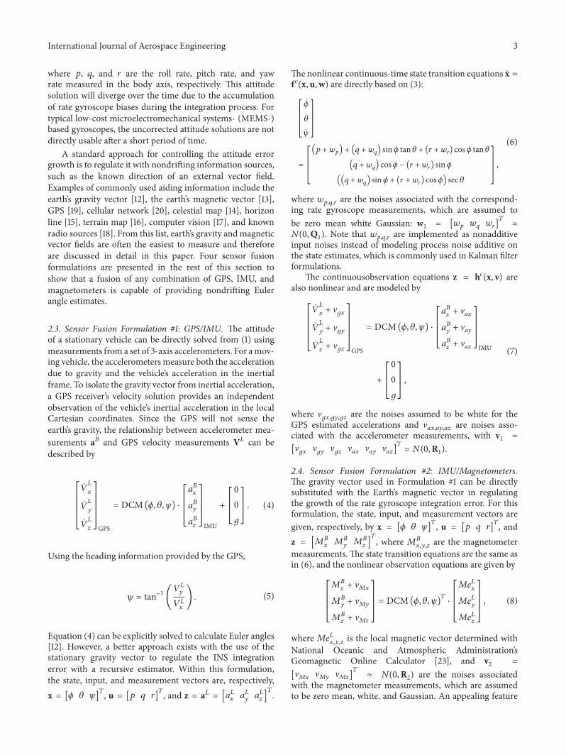

International Journal of
AerospaceEngineeringHindawi Publishing Corporationhttpwwwhindawicom Volume 2014
RoboticsJournal of
Hindawi Publishing Corporationhttpwwwhindawicom Volume 2014
Hindawi Publishing Corporationhttpwwwhindawicom Volume 2014
Active and Passive Electronic Components
Control Scienceand Engineering
Journal of
Hindawi Publishing Corporationhttpwwwhindawicom Volume 2014
International Journal of
RotatingMachinery
Hindawi Publishing Corporationhttpwwwhindawicom Volume 2014
Hindawi Publishing Corporation httpwwwhindawicom
Journal ofEngineeringVolume 2014
Submit your manuscripts athttpwwwhindawicom
VLSI Design
Hindawi Publishing Corporationhttpwwwhindawicom Volume 2014
Hindawi Publishing Corporationhttpwwwhindawicom Volume 2014
Shock and Vibration
Hindawi Publishing Corporationhttpwwwhindawicom Volume 2014
Civil EngineeringAdvances in
Acoustics and VibrationAdvances in
Hindawi Publishing Corporationhttpwwwhindawicom Volume 2014
Hindawi Publishing Corporationhttpwwwhindawicom Volume 2014
Electrical and Computer Engineering
Journal of
Advances inOptoElectronics
Hindawi Publishing Corporation httpwwwhindawicom
Volume 2014
The Scientific World JournalHindawi Publishing Corporation httpwwwhindawicom Volume 2014
SensorsJournal of
Hindawi Publishing Corporationhttpwwwhindawicom Volume 2014
Modelling amp Simulation in EngineeringHindawi Publishing Corporation httpwwwhindawicom Volume 2014
Hindawi Publishing Corporationhttpwwwhindawicom Volume 2014
Chemical EngineeringInternational Journal of Antennas and
Propagation
International Journal of
Hindawi Publishing Corporationhttpwwwhindawicom Volume 2014
Hindawi Publishing Corporationhttpwwwhindawicom Volume 2014
Navigation and Observation
International Journal of
Hindawi Publishing Corporationhttpwwwhindawicom Volume 2014
DistributedSensor Networks
International Journal of


![MSE Minimization and Fault-Tolerant Data Fusion for Multi ... · Data fusion methods can also be used to detect faulty sensors [3] and deliver fault-tolerant measurements. This is](https://static.fdocuments.net/doc/165x107/5f3e6e6680ecd5749113c0dc/mse-minimization-and-fault-tolerant-data-fusion-for-multi-data-fusion-methods.jpg)