RES G series TRAining CEntre Burner Settings. General overview Burner is built with our standard...
20
RES G series TRAining CEntre Burner Settings
-
Upload
richard-holt -
Category
Documents
-
view
222 -
download
0
Transcript of RES G series TRAining CEntre Burner Settings. General overview Burner is built with our standard...

RES G series
TRAining CEntre
Burner Settings

General overview
Burner is built with our standard components
RIELLO’s pump RIELLO’s motor
RIELLO’s Control Box

New specific components
Combustion head
Air supply system

Combustion Head

Combustion Head
Blast tube with recirculation slots
“Cup”with main central hole
and 4 air pipesAir nozzle with
swirl inside
Sleeve

Combustion Head
Section view
Head setting system
Combustion head

Combustion Head
Head setting system
Setting screw
index
Curve bracket
spring
Nozzle holder
cone

Combustion Head
Head setting system

Combustion Head
Combustion head
1° air2° air
3° air
Recirculation flow Air nozzle
“Cup”with main central holeand 4 air pipes
Blast tube with recirculation slots
Air swirl

Blast tube with recirculation slots
Cup with 4 pipes and air nozzle’s centring system
Air nozzle with its internal swirl

Combustion Head
Main settings
1 - Nozzle air’s position2 - Recirculation slots’s width

Combustion Head Overall dimensions
Rate[kg/h] 1.3-2.6 2.3-3.6 3.4-4.3
E [mm] +2.3 / 0 +1 / -1.5 -1 / -3.2 adjust
G [mm] 2 / 1.5 4 / 6 8 / 8 adjust
A [mm] 100 100 100 B [mm] 14 18 21 check C [mm] 23 25 27 checkD [mm] 4 5 5 check
F [mm] 3 6 6 check
H [mm] 173 225 225
Head T1 T2 T3
E

Supply Air system

System was born by a “PUNKER” and RIELLO project
and is composed by:
Air Fan 120 mm, H: 62 mm with 33 blades
Chassis
Fixed and adjustable air dampers
Suction pipe
Adjustable Knob
Suction plate

Supply Air system
Suction plate + damper(adjustable only with T1 head)The device’s position defined the fan’s performance
Fan andfixed damper
Suction pipe + adjustable knob(to achieve the correctair excess)
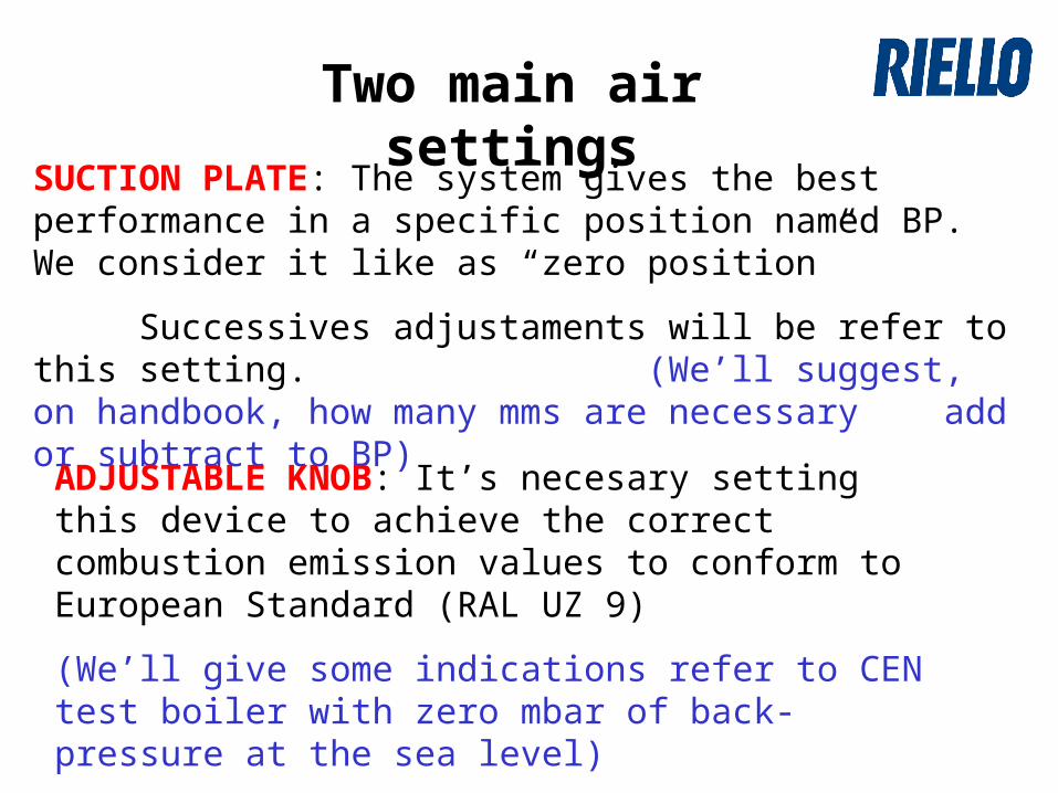
Two main air settings
SUCTION PLATE: The system gives the best performance in a specific position named BP. We consider it like as “zero position”
Successives adjustaments will be refer to this setting. (We’ll suggest, on handbook, how many mms are necessary add or subtract to BP)
ADJUSTABLE KNOB: It’s necesary setting this device to achieve the correct combustion emission values to conform to European Standard (RAL UZ 9)
(We’ll give some indications refer to CEN test boiler with zero mbar of back-pressure at the sea level)
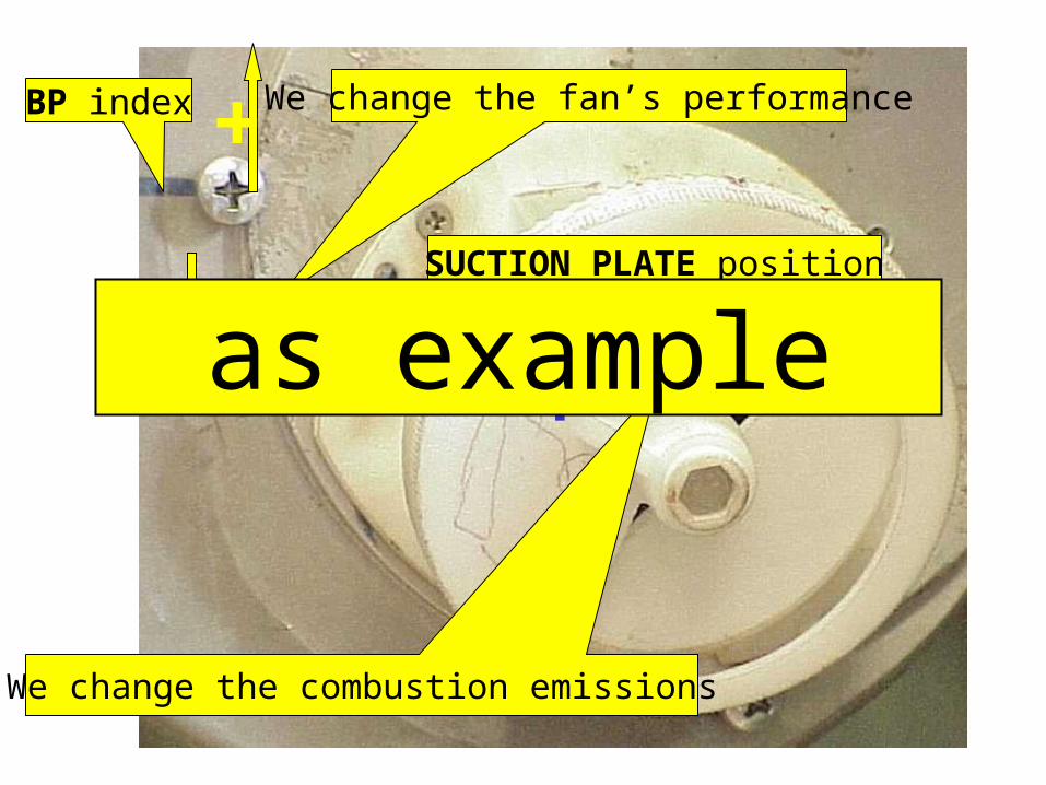
BP index
SUCTION PLATE position
- X mm
We change the fan’s performance
-
+
+ -
We change the combustion emissions
as example

Supplementary details
Damper’s position inside the fandefine the system’s performance
Small mechanical tollerance degreebetween different devices to increase
fan’s performance
Special gasket all aroundto avoid any air leakages
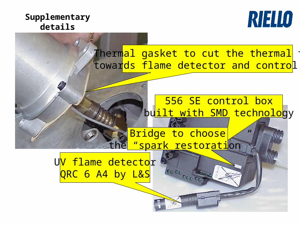
Thermal gasket to cut the thermal flowtowards flame detector and control box
556 SE control boxbuilt with SMD technology
UV flame detectorQRC 6 A4 by L&S
Bridge to choosethe “spark restoration”
Supplementary details
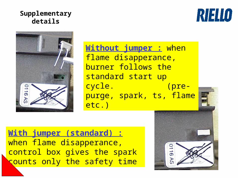
Without jumper : when flame disapperance, burner follows the standard start up cycle. (pre-purge, spark, ts, flame etc.)
With jumper (standard) : when flame disapperance, control box gives the spark counts only the safety time
Supplementary details