REQUIREMENTS FOR MCS CONTRACTORS …regulations.completepicture.co.uk/pdf/Mcs/MIS 3001 Issue 4.2...
38
This Microgeneration Installation Standard is the property of Department of Energy and Climate Change (DECC), 3 Whitehall Place, London,SW1A 2HH. © DECC 2009 Microgeneration Installation Standard: MIS 3001 REQUIREMENTS FOR MCS CONTRACTORS UNDERTAKING THE SUPPLY, DESIGN, INSTALLATION, SET TO WORK, COMMISSIONING AND HANDOVER OF SOLAR HEATING MICROGENERATION SYSTEMS Issue 4.2
Transcript of REQUIREMENTS FOR MCS CONTRACTORS …regulations.completepicture.co.uk/pdf/Mcs/MIS 3001 Issue 4.2...
This Microgeneration Installation Standard is the property of Department of Energy and Climate Change (DECC), 3 Whitehall Place, London,SW1A 2HH.
© DECC 2009
Microgeneration Installation Standard: MIS 3001
REQUIREMENTS FOR MCS CONTRACTORS
UNDERTAKING THE SUPPLY, DESIGN,
INSTALLATION, SET TO WORK, COMMISSIONING
AND HANDOVER OF SOLAR HEATING
MICROGENERATION SYSTEMS
Issue 4.2
Issue: 4.2 MICROGENERATION INSTALLATION
STANDARD
MIS: 3001
Date: 01/05/2015 Page 2 of 38
This Standard has been approved by the Steering Group of the Microgeneration Certification Scheme (MCS).
This Standard was prepared by the MCS Working Group 1 ‘Solar Heating Systems’.
REVISION OF MICROGENERATION INSTALLATION STANDARDS
Microgeneration Installation Standards will be revised by issue of revised editions or amendments. Details will be posted on the website at www.microgenerationcertification.org.
Technical or other changes which affect the requirements for the approval or certification of the product or service will result in a new issue. Minor or administrative changes (e.g. corrections of spelling and typographical errors, changes to address and copyright details, the addition of notes for clarification etc.) may be made as amendments.
The issue number will be given in decimal format with the integer part giving the issue number and the fractional part giving the number of amendments (e.g. Issue 3.2 indicates that the document is at Issue 3 with 2 amendments).
Users of this Standard should ensure that they possess the latest issue and all amendments.
Issue: 4.2 MICROGENERATION INSTALLATION
STANDARD
MIS: 3001
Date: 01/05/2015 Page 3 of 38
TABLE OF CONTENTS
FOREWORD ................................................................................................................... 4
1 SCOPE .............................................................................................................. 6
2 DEFINITIONS .................................................................................................... 6
3 REQUIREMENTS FOR THE MCS CONTRACTOR .......................................... 8
3.1 Capability ................................................................................................. 8
3.2 Quality Management System (QMS) ........................................................ 8
3.3 Subcontracting ......................................................................................... 8
3.4 Consumer Code of Practice ...................................................................... 9
4 DESIGN AND INSTALLATION REQUIREMENTS ........................................... 10
4.1 Regulations ............................................................................................ 10
4.2 Manufacturer’s Instructions ..................................................................... 11
4.3 Design and Installation ........................................................................... 11
4.4 Safety and Durability .............................................................................. 11
4.5 Solar Heating System performance ........................................................ 14
4.6 Site specific issues ................................................................................. 18
4.7 Commissioning ....................................................................................... 22
4.8 Equipment .............................................................................................. 22
5 ROLES AND COMPETENCY REQUIREMENTS ............................................ 23
6 HANDOVER REQUIREMENTS ....................................................................... 24
7 REGIONAL OFFICES...................................................................................... 25
8 PUBLICATIONS FOR REFERENCE & FURTHER READING ......................... 25
APPENDIX A: ROLES AND COMPETENCY REQUIREMENTS ................................... 27
APPENDIX B: MINIMUM REQUIREMENTS - HANDOVER DOCUMENTATION .......... 28
APPENDIX C: BUILDING REGULATIONS ................................................................... 34
APPENDIX D: LABELLING ........................................................................................... 36
AMENDMENTS ISSUED SINCE PUBLICATION .......................................................... 37
Issue: 4.2 MICROGENERATION INSTALLATION
STANDARD
MIS: 3001
Date: 01/05/2015 Page 4 of 38
FOREWORD
The following document contains provisions, which, through reference in this text,
constitute normative or informative provisions of this document MIS 3001. At the time of
publication, the editions indicated were valid. All documents are subject to revision, and
parties applying this document MIS 3001 are encouraged to investigate the possibility of
applying the most recent editions of the documents referenced.
The following document MIS 3001 issue 4.2 is a minor update to MIS 3001 issue 4.1. It
is available for reference from the date of publication (01/05/2015). MCS Contractors of
microgeneration systems who are certificated in accordance with MIS 3001 may
commence working in accordance with this update from the date of publication
(01/05/2015). MCS Contractors of microgeneration systems who are certificated in
accordance with MIS 3001 shall commence working in accordance with this update from
the date of implementation (01/08/2015).
This Standard identifies the evaluation and assessment practices to be undertaken by
the Certification Bodies for MCS for the purposes of approval and listing of MCS
Contractors undertaking the supply, design, installation, set to work, commissioning and
handover of Solar Heating Systems. The listing and approval is based on evidence
acceptable to the Certification Body:
that the Solar Heating System or service meets the Standard;
that the MCS Contractor has staff, processes and systems in place to
ensure that the Solar Heating System or service delivered meets the
Standard;
And on;
periodic audits of the MCS Contractor including testing as appropriate;
compliance with the contract for the MCS listing and approval including
agreement to rectify faults as appropriate.
This Standard shall be used in conjunction with the MCS 001 scheme document and any
other guidance and / or supplementary material available on the MCS website
specifically referring to this Microgeneration Certification Standard (MIS 3001). A
Issue: 4.2 MICROGENERATION INSTALLATION
STANDARD
MIS: 3001
Date: 01/05/2015 Page 5 of 38
catalogue of guidance and supplementary material to be read in conjunction with MIS
3001 can be found on the MCS website, www.microgenerationcertification.org.
Government defines microgeneration as the production of heat and/or electricity on a
small-scale from a low carbon source. The various technologies have the potential to
help achieve the objectives of tackling climate change, ensuring reliable energy and
tackling fuel poverty.
The objective of government's Microgeneration Strategy is to create conditions under
which microgeneration becomes a realistic alternative or supplementary energy
generation source for the householder, for the community, and for small businesses.
Notes:
This Microgeneration Installation Standard makes use of the terms ‘must’, ‘shall’ and
‘should’ when prescribing certain requirements and procedures. In the context of this
document:
the term ‘must’ identifies a requirement by law at the time of publication;
the term ‘shall’ prescribes a requirement or procedure that is intended to be
complied with in full and without deviation;
the term ‘should’ prescribes a requirement or procedure that is intended to be
complied with unless reasonable justification can be given.
Compliance with this Microgeneration Installation Standard does not of itself confer
immunity from legal obligations.
Users of Microgeneration Installation Standards should ensure that they possess the
latest issue and all amendments.
The Steering Group welcomes comments of a technical or editorial nature and these
should be addressed to “The Secretary” at [email protected].
Listed products and services may be viewed on the website:
www.microgenerationcertification.org.
Issue: 4.2 MICROGENERATION INSTALLATION
STANDARD
MIS: 3001
Date: 01/05/2015 Page 6 of 38
1 SCOPE
1.1 This Standard specifies the requirements of the MCS for MCS Contractors
undertaking the supply, design, installation, set to work, commissioning and handover of
Solar Heating Systems to supply domestic hot water, space heating and swimming pools
for permanent buildings.
1.2 Multiple MCS certified solar collectors may be used in a single installation, but the
individual output for a single appliance shall not exceed 45 kWth as defined by the MCS
product certification scheme document MCS 004.
1.3 The scope of this MCS Installation Standard is limited to installations with a design
heat load requirement of up to 70 kWth.
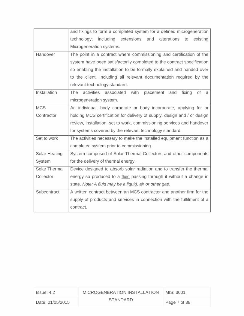
2 DEFINITIONS
Commissioning The advancement of an installation from the state of setting to work of
an installation, the regulation of the system and the fine tuning of the
static completion to full working order to the specified requirements.
Commissioning includes recording all relevant measurements, flow
rates and / or test results, and includes the preparation and submission
of a commissioning report or certificate as required by the relevant
technology standard that shall confirm that the system is capable of
delivering the performance quoted to the customer.
Contract An undertaking for the design, supply, installation, set to work,
commissioning and handover of systems covered by the relevant
technology standard. All contracts must be written to be compliant with
MCS requirements.
Design The formulation of a written plan including a specific list of products
Issue: 4.2 MICROGENERATION INSTALLATION
STANDARD
MIS: 3001
Date: 01/05/2015 Page 7 of 38
and fixings to form a completed system for a defined microgeneration
technology; including extensions and alterations to existing
Microgeneration systems.
Handover The point in a contract where commissioning and certification of the
system have been satisfactorily completed to the contract specification
so enabling the installation to be formally explained and handed over
to the client. Including all relevant documentation required by the
relevant technology standard.
Installation The activities associated with placement and fixing of a
microgeneration system.
MCS
Contractor
An individual, body corporate or body incorporate, applying for or
holding MCS certification for delivery of supply, design and / or design
review, installation, set to work, commissioning services and handover
for systems covered by the relevant technology standard.
Set to work The activities necessary to make the installed equipment function as a
completed system prior to commissioning.
Solar Heating
System
System composed of Solar Thermal Collectors and other components
for the delivery of thermal energy.
Solar Thermal
Collector
Device designed to absorb solar radiation and to transfer the thermal
energy so produced to a fluid passing through it without a change in
state. Note: A fluid may be a liquid, air or other gas.
Subcontract A written contract between an MCS contractor and another firm for the
supply of products and services in connection with the fulfilment of a
contract.
Issue: 4.2 MICROGENERATION INSTALLATION
STANDARD
MIS: 3001
Date: 01/05/2015 Page 8 of 38
3 REQUIREMENTS FOR THE MCS CONTRACTOR
3.1 Capability
3.1.1 MCS Contractors shall have the capability and capacity to undertake the supply,
design, installation, set to work, commissioning and handover of solar heating
microgeneration systems.
3.1.2 Where MCS Contractors do not engage in the design or supply of Solar Heating
Systems, but work solely as an MCS Contractor for a client who has already
commissioned a system design; then the MCS Contractor shall be competent to review
and verify that the design would meet the design requirements set out in this Standard
and this should be recorded.
3.2 Quality Management System (QMS)
3.2.1 MCS Contractors shall operate a satisfactory Quality Management System which
meets the additional requirements set out in the scheme document MCS 001.
3.3 Subcontracting
3.3.1 In installations for private customers, any work within the scope of the scheme not
undertaken by employees of the MCS Contractor shall be managed through a formal
subcontract agreement between the two parties in accordance with the policies and
procedures employed by the MCS Contractor. These procedures shall ensure that the
subcontractor undertakes the work in accordance with the requirements of this standard.
3.3.2 In other situations (for example new build or for commercial customers), it is
permissible for the physical installation, setting to work and commissioning to be
undertaken by others (i.e. not subcontracted to the MCS Contractor) provided that:
3.3.3 A contract between the MCS Contractor and the commercial client details
obligations on the client to include that evidence of skills and training of those employed
Issue: 4.2 MICROGENERATION INSTALLATION
STANDARD
MIS: 3001
Date: 01/05/2015 Page 9 of 38
by the client to do elements of work not undertaken by the MCS Contractor. This is to be
made available to the MCS Contractor to ensure that the competence requirements of
this Standard are met and that access to the site for training and supervision in
accordance with the following sections is agreed in advance.
3.3.4 The MCS Contractor provides additional product-specific training for those
undertaking the work not undertaken by the MCS Contractor.
3.3.5 The MCS Contractor assesses a sample number of installations under the
Contract which is not less than the square root of the number of installations rounded up
to the nearest whole number (e.g. for a new build site of 50 installations, a minimum of 8
are assessed).
3.3.6 The MCS Contractor assumes responsibility at handover that the installation is in
full compliance with the Standard.
3.4 Consumer Code of Practice
3.4.1 The MCS Contractor shall be a member of and, when dealing with domestic
consumers, comply with a Code of Practice (Consumer Code), which is relevant to the
scope of their business in the microgeneration sector and which is approved by the
Trading Standards Institute (or formally approved under the Office of Fair Trading (OFT)
prior to April 1st 2013).
Issue: 4.2 MICROGENERATION INSTALLATION
STANDARD
MIS: 3001
Date: 01/05/2015 Page 10 of 38
4 DESIGN AND INSTALLATION REQUIREMENTS
4.1 Regulations
4.1.1 All applicable regulations and directives must be met in full. It should be noted that
regulations that must be applied may be different in England, Northern Ireland, Scotland
and Wales. MCS Contractors shall ensure they have a system to identify all applicable
regulations and changes to them.
4.1.2 All work, and working practices, must be in compliance with all relevant Health and
Safety regulations and risk assessments shall be conducted before any work on site is
commenced.
4.1.3 All MCS Contractors shall make their customers aware of all permissions and
approvals required for the installation.
4.1.4 The MCS Contractor shall assess the building using a competent professional
experienced in solar thermal systems to ensure that the site is suitable for the installation
and that the building will meet the requirements of the Building Regulations (in particular
those relating to energy efficiency) and other regulations applicable to their work during
and following installation.
4.1.5 Where required, planning permission shall be obtained before work is commenced.
4.1.6 Where work is undertaken that is notifiable under the Building Regulations it shall
be made clear to the customer who shall be responsible for this notification.
4.1.7 The MCS Contractor shall ensure that this notification has been completed prior to
handing over the installation. Self-certification, in lieu of building control approval, is only
permitted where installation and commissioning is undertaken by a person deemed
competent and registered with a Competent Persons Scheme (CPS) approved by the
Department for Communities and Local Government (DCLG) for the scope of work being
undertaken. Further details can be found at http://www.competentperson.co.uk.
Issue: 4.2 MICROGENERATION INSTALLATION
STANDARD
MIS: 3001
Date: 01/05/2015 Page 11 of 38
4.2 Manufacturer’s Instructions
4.2.1 Solar heating systems shall be installed such that all manufacturers’ instructions
are followed. Where manufacturer’s instructions conflict with the requirement of this
Standard, the MCS contractor shall conform to this standard unless it can be proven that
conformance to the manufacturer’s instructions will facilitate a system that is more
efficient and no less safe or durable than if the requirements of this Standard had been
met.
4.3 Design and Installation
4.3.1 The requirements outlined in MIS 3001 shall be met when designing, specifying
and installing a Solar Heating System.
4.4 Safety and Durability
Solar Heating Systems shall:
4.4.1 Incorporate safety devices to ensure that the temperature of the stored water
does not exceed 100oC at any time and comply with national regulations.
4.4.2 Safeguard against pressures exceeding the pressure rating of the weakest
component.
4.4.3 Incorporate a means to limit the temperature of the water at all points of use after
an assessment of scald risk factors.
NOTE:For domestic applications this requirement might be met through the provision of
thermostatic mixing valves (TMVs) within 2,000mm of all points of use set at no more
than 46oC (or lower dependent upon the point of use in question) OR the provision of
TMVs at the outlets from the hot water cylinder set at 55oC – 60oC OR the provision of a
thermostatic device to limit the solar input to the hot water cylinder OR a combination of
the above.
4.4.4 Incorporate a means to control bacterial growth (including Legionella bacteria) in
domestic hot water.
Notes:
Issue: 4.2 MICROGENERATION INSTALLATION
STANDARD
MIS: 3001
Date: 01/05/2015 Page 12 of 38
(a) A solar cylinder providing a direct feed of pre-heated water to a combination boiler is
unlikely to meet this requirement without further bacterial control measures such as a
daily heat pasteurisation of the entire cylinder. A solar cylinder (primary store) providing
indirect feed (internal or external heat exchanger) to a combination boiler represents a
lower risk and may not require further bacterial control measures subject to the bacterial
risk assessment.
(b) A Solar Heating System comprising a twin coil cylinder is likely to meet this
requirement subject to the boiler-heated zone being heated daily to 60oC for 1 hour and
its volume exceeding the predicted daily hot water demand of the building.
(c) Further guidance can be found within the Health and Safety Executive Approved
Code of Practice L8 document (HSE ACoP L8).
4.4.5 Ensure that future performance and safety are not significantly affected by
mineral deposits forming in the solar primary circuit.
Note: This requirement is met by indirect Solar Heating Systems where fresh water is
not continually being introduced to the solar primary circuit.
4.4.6 Incorporate means to protect the Solar Heating System from damage due to
freezing.
4.4.7 Not expose components, including pipe work, joints, insulation, expansion
vessels and pipe supports to temperatures outside their designed temperature range.
Note: Many standard heating components may not be suitable for the temperatures and
pressures present in solar primary circuits.
4.4.8 Be designed such that there is auto-resume of normal operation after stagnation
without user intervention (often referred to as “intrinsically secure”).
Note: Stagnation can be defined as a state whereby flow within the primary solar circuit
stops whilst the Solar Thermal Collector is still exposed to solar radiation. Stagnation
can occur through purposeful temperature control of the water in the hot water cylinder
or through a system fault (e.g. pump or electrical failure). On sealed systems, this
requirement would be met through the provision of sufficient capacity in an expansion
vessel to accommodate the volume of any vapour created within the Solar Thermal
Issue: 4.2 MICROGENERATION INSTALLATION
STANDARD
MIS: 3001
Date: 01/05/2015 Page 13 of 38
Collector and connected pipe work along with the provision of a valve left in the closed
position before any automatic air vent.
4.4.9 Ensure the supply of pre-heated water to the cold inlet of an instantaneous water
heating appliance is at a temperature no higher than the maximum cold inlet
temperature for the appliance as specified by the manufacturer.
Note: Special consideration should be given to requirements 4.4.3 and 4.4.4 in this
situation.
4.4.10 Be designed and installed to allow for safe de-commissioning.
Note: This requirement is UNLIKELY to be met without the provision of sufficient,
suitably located, drain points to allow draining of all parts of the Solar Heating System
(primary and secondary circuits).
4.4.11 Protect against burns and unnecessary heat loss by the insulation of all pipes,
with the exception of branch pipes to expansion vessels.
Note: This includes all of the pipes, joints and components in the solar primary circuit
from the Solar Thermal Collector to the cylinder via the pump station. It also includes all
other pipes connected to the hot water cylinder (boiler primary and hot water draw off),
as far as is reasonably practicable, but in any event it must include at least the first one
metre of any pipe from the hot water cylinder.
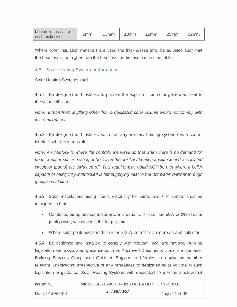
For the solar primary circuit, the following table of minimum insulation thickness is
deemed to satisfy both this requirement and Part L of the Building Regulations in
England and Wales.
Table 1. Minimum required wall thickness for High Temperature EPDM based rubber
insulation products.
Minimum required wall thickness for High Temperature EPDM based rubber insulation products used for solar primary circuits assuming a mean flow temperature of 50oC and a conductivity of 0.038 W/mK
Pipe Outside Diameter
10mm 12mm 15mm 22mm 28mm 35mm
Issue: 4.2 MICROGENERATION INSTALLATION
STANDARD
MIS: 3001
Date: 01/05/2015 Page 14 of 38
Minimum insulation wall thickness
9mm 13mm 13mm 19mm 25mm 32mm
Where other insulation materials are used the thicknesses shall be adjusted such that
the heat loss is no higher than the heat loss for the insulation in the table.
4.5 Solar Heating System performance
Solar Heating Systems shall:
4.5.1 Be designed and installed to prevent the export of non solar generated heat to
the solar collectors.
Note: Export from anything other than a dedicated solar volume would not comply with
this requirement.
4.5.2 Be designed and installed such that any auxiliary heating system has a control
interlock wherever possible.
Note: An interlock is where the controls are wired so that when there is no demand for
heat for either space heating or hot water the auxiliary heating appliance and associated
circulator (pump) are switched off. This requirement would NOT be met where a boiler
capable of being fully interlocked is left supplying heat to the hot water cylinder through
gravity circulation.
4.5.3 Solar installations using mains electricity for pump and / or control shall be
designed so that:
Combined pump and controller power is equal to or less than 50W or 2% of solar
peak power, whichever is the larger; and
Where solar peak power is defined as 700W per m² of aperture area of collector.
4.5.4 Be designed and installed to comply with relevant local and national building
legislation and associated guidance such as Approved Documents L and the Domestic
Building Services Compliance Guide in England and Wales, or equivalent in other
relevant jurisdictions. Irrespective of any references to dedicated solar volume in such
legislation or guidance, Solar Heating Systems with dedicated solar volume below that
Issue: 4.2 MICROGENERATION INSTALLATION
STANDARD
MIS: 3001
Date: 01/05/2015 Page 15 of 38
required by Approved Documents L and the Domestic Building Services Compliance
Guide in England and Wales, are permitted provided that:
a) Other than having a lower dedicated solar volume, the Solar Heating
System complies with all relevant recommendations within such relevant
legislation or guidance.
b) Solar Heating System performance is optimised by controlling the timing
of backup (auxiliary / non-solar) sources of water heating, for example by:
i. During daytime, avoiding backup heating and minimising daytime
"boost" to short periods only. Also, during the evening after the sun
can no longer significantly contribute heat, timing daily backup
heating to heat the water to 60oC and hold it there for one hour,
and ideally to switch it off before all baths or showers are taken.
This way the amount of cool water in the cylinder available for
solar heating the next day is maximised, and solar energy
performance is increased;
ii. A full explanation being given to the customer of all relevant
controls including an explanation that any changes could reduce
the effectiveness of the Solar Heating System;
iii. Affixing a durable label at all relevant solar, and backup, system
time-control points to communicate the importance to Solar
Heating System performance of the timing of backup heating.
c) Where the Solar Heating System is connected to an existing cylinder
then:
i. The thermal insulation of the hot water cylinder, and all pipes
connected to it, shall be upgraded to a level at least equivalent to
that applicable to new installations under relevant legislation and
guidance. For cylinders with factory applied insulation, this
condition can be satisfied if the cylinder standing heat loss is
certified to comply with Section 12 of BS1566-1: 2002 or
equivalent. Where this certification is not apparent, or where the
cylinder does not have factory-applied insulation, the MCS
Contractor shall install additional insulation certified to comply with
BS5615: 1985;
Issue: 4.2 MICROGENERATION INSTALLATION
STANDARD
MIS: 3001
Date: 01/05/2015 Page 16 of 38
ii. Backup heating system controls shall be upgraded in accordance
with 4.4.3;
iii. Proper duty of care shall be exercised to ensure that the hot water
cylinder is fit for purpose as regards its mechanical integrity.
Consideration shall be given to scale build-up affecting overall
(solar and backup) system efficiency, damage, and deterioration
caused by corrosion. Such issues shall be considered in the
context of any additional stress placed upon the cylinder through
the connection of the Solar Heating System (e.g. thermal stress or
additional system pressure);
iv. Where indirectly connected via a heat exchanger that this heat
exchanger shall have a surface area of at least 10% of the surface
area of the Solar Thermal Collector’s aperture area.
Note: Alternative justifications of Solar Heating System performance shall be considered
by the Certification Body. The Certification Body may, at its discretion, charge a fee for
such consideration.
4.5.5 Be accompanied by an estimate of annual energy performance calculated as
follows;
For domestic installations providing only domestic hot water:
Calculate the annual solar energy input to the cylinder in accordance with MCS 024
Solar Domestic Hot Water Energy Calculation.
The energy estimate shall be communicated with the client at or before the Contract is
awarded and shall be accompanied by the following disclaimer:
“The performance of solar heating systems is impossible to predict with
certainty due to the variability in the amount of solar radiation (sunlight) from
location to location and from year to year together with variability in heat
demand. This estimate is based upon the standard MCS procedure and is given
as guidance only. It should not be considered as a guarantee of performance."
Issue: 4.2 MICROGENERATION INSTALLATION
STANDARD
MIS: 3001
Date: 01/05/2015 Page 17 of 38
For Solar Heating Systems which provide a solar dedicated volume that meets the solar
dedicated volume requirements of the Domestic Building Services Compliance Guide
add:
“The performance of solar heating systems can be influenced by the actions of
the user, especially by timing back-up heating to finish before hot water use.
The customer could achieve an energy benefit higher than the estimate by
following operating instructions.”
For Solar Heating Systems which provide a solar dedicated volume that does not meet
the solar dedicated volume requirements of the Domestic Building Services Compliance
Guide add:
“The performance of solar heating systems can be influenced by the actions of
the user, especially by timing back-up heating to finish before hot water use.
The customer could achieve energy savings higher than the estimate by
carefully following operating instructions. The type of solar heating system in
this quotation is sensitive to user behaviour and the customer should be aware
that failure to follow operating instructions could diminish the solar energy
performance.”
For Solar Heating Systems outside the scope of MCS 024, an approved means of
estimating energy performance shall be provided under the provisions of the SAP
methodology Appendix Q (special features and specific data).
Additional estimates may be provided using an alternative methodology but any such
estimates must clearly describe and justify the method employed and the factors used.
These additional estimates must not be given greater prominence than the estimation
method specified in this standard and shall not be used on the MCS certificate. In
addition, it must be accompanied by warning stating that it should be treated with caution
if it is significantly greater than the result given by the standard method.
For non-domestic installations and Solar Heating Systems outside the scope of SAP and
MCS 024:
Calculate the annual solar energy input to the system using proprietary software. The
software package, version number and all simulation inputs and outputs should be fully
Issue: 4.2 MICROGENERATION INSTALLATION
STANDARD
MIS: 3001
Date: 01/05/2015 Page 18 of 38
communicated to the client at or before the point that the contract is awarded. All input
assumptions must be stated and must be appropriate to the installation.
4.6 Site specific issues
The following issues shall be addressed in the design of Solar Heating Systems for each
installation:
4.6.1 The roof structure shall be checked to ensure it can withstand the imposed loads
as calculated (see Note below). If there is any doubt, a structural engineer must be
consulted.
Note: Where a new roof incorporates new trussed rafters, the designer of those trussed
rafters shall be advised of the position, number and weight of the solar collectors to be
mounted onto the roof structure. Reference in this standard to a structural engineer
means an individual or organisation holding relevant professional indemnity insurance
and is a member of a relevant professional body such as the Institution of Structural
Engineers.
4.6.2 The Solar Thermal Collector and its fixings (type and quantity) shall be of
sufficient strength to withstand the imposed (dead load) and wind uplift loads. For each
site the imposed wind and snow loads shall be derived using the procedures within
Eurocode 1 (BS EN1991-1) multiplied by a Load Safety Factor (SFL) of 1.35.
The pressure coefficients (Cp) used to calculate wind loads shall be derived as follows:
For Solar Thermal Collectors that are mounted above, and parallel to, an
inclined roof where there is a clear gap between the array and the roof - the
pressure coefficients shall be taken from BRE Digest 489 or from recognised
test data commissioned for the specific purpose of determining the wind
loads on solar systems.
For flat roof systems - the pressure coefficients shall be taken from BRE
Digest 489 or from recognised test data commissioned for the specific
purpose of determining the wind loads on solar systems.
For roof integrated, nominally airtight systems - the pressure coefficients shall
be taken from Eurocode-1.
Issue: 4.2 MICROGENERATION INSTALLATION
STANDARD
MIS: 3001
Date: 01/05/2015 Page 19 of 38
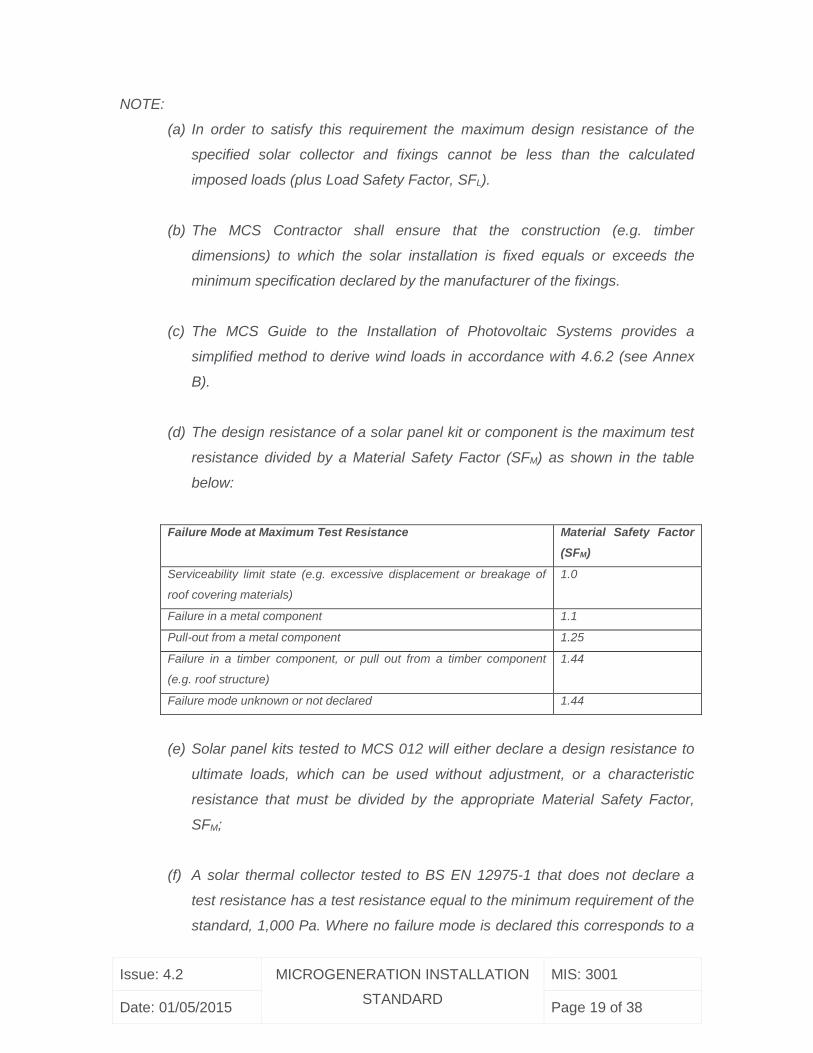
NOTE:
(a) In order to satisfy this requirement the maximum design resistance of the
specified solar collector and fixings cannot be less than the calculated
imposed loads (plus Load Safety Factor, SFL).
(b) The MCS Contractor shall ensure that the construction (e.g. timber
dimensions) to which the solar installation is fixed equals or exceeds the
minimum specification declared by the manufacturer of the fixings.
(c) The MCS Guide to the Installation of Photovoltaic Systems provides a
simplified method to derive wind loads in accordance with 4.6.2 (see Annex
B).
(d) The design resistance of a solar panel kit or component is the maximum test
resistance divided by a Material Safety Factor (SFM) as shown in the table
below:
Failure Mode at Maximum Test Resistance Material Safety Factor
(SFM)
Serviceability limit state (e.g. excessive displacement or breakage of
roof covering materials)
1.0
Failure in a metal component 1.1
Pull-out from a metal component 1.25
Failure in a timber component, or pull out from a timber component
(e.g. roof structure)
1.44
Failure mode unknown or not declared 1.44
(e) Solar panel kits tested to MCS 012 will either declare a design resistance to
ultimate loads, which can be used without adjustment, or a characteristic
resistance that must be divided by the appropriate Material Safety Factor,
SFM;
(f) A solar thermal collector tested to BS EN 12975-1 that does not declare a
test resistance has a test resistance equal to the minimum requirement of the
standard, 1,000 Pa. Where no failure mode is declared this corresponds to a
Issue: 4.2 MICROGENERATION INSTALLATION
STANDARD
MIS: 3001
Date: 01/05/2015 Page 20 of 38
design resistance of 694 Pa (i.e. 1000/1.44). A solar thermal collector tested
to BS EN ISO9806 that does not declare a test resistance has a test
resistance equal to the minimum requirement of the standard, 2,400 Pa.
Where no failure mode is declared this corresponds to a design resistance of
1666 Pa (i.e. 2400/1.44).;
(g) For installations assembled from separate components not tested together as
a kit, the roof fixing components shall be tested to MCS012 and the declared
design resistance of each component and Solar Thermal Collector must
independently exceed the calculated imposed load (plus Load Safety Factor,
SFL); and,
(h) For the avoidance of doubt, adding more fixing brackets to the number used
in testing of the solar thermal collector does not increase the resistance of the
collector beyond its tested value.
4.6.3 Where a Solar Thermal Collector is integrated in roof forming the primary roof
covering, the location of the collector shall be in accordance with local regulations in
respect of external spread of flame accounting for the declared fire class of the
combined collector and roof integration kit.
Note: To demonstrate compliance with building regulations in England and Wales,
Scotland and Northern Ireland, a fire resistance classification to BS476-3 or BS EN
13501-5 (Test 4) is required. Products tested to MCS 012 will show the fire classification
on the test report.
4.6.4 Solar Thermal Systems shall not adversely affect the weather tightness of the
structure to which they are fitted. The system should be designed and installed to ensure
this is maintained for the life of the system.
4.6.5 For roof integrated systems, the weather tightness of the system shall be tested
and certified to be the same or better than the roof or cladding systems they are
replacing and to not adversely affect the weather tightness of the surrounding covering.
Issue: 4.2 MICROGENERATION INSTALLATION
STANDARD
MIS: 3001
Date: 01/05/2015 Page 21 of 38
Note: an acceptable means of demonstrating compliance with this requirement is to use
a roof integration system suitable for the class of roof covering and roof pitch and tested
to MCS 012.
4.6.6 For above roof systems, the fixings shall not affect the weather tightness of the
roof they are fitted to. For example, systems attached to pitched tile roofs should be
designed and installed such that the fixing brackets do not displace the tiles and cause
gaps more than naturally occurs between the tiles. Fixing methods shall not subject roof
coverings to imposed loads that may degrade their primary purpose of maintaining
weather-tightness.
Tiles or slates removed for fixing a mounting bracket should be re-attached to include a
means of mechanical fixing.
Notes:
a) An acceptable means of demonstrating compliance with this requirement is to
use roof-fixing brackets tested to MCS 012 and suitable for the class of roof
covering and roof pitch.
b) Historically, some mounting systems on slate or tile roofs have relied on a simple
“through bolt” approach. However, this fixing method has the potential for the
fixing bolts or sealing washer cracking the slates/tiles beneath them. It can also
present difficulties with ensuring the long term weather tightness and durability of
the roof penetration.
Therefore through tile or slate penetrations (for bolts and pipes) shall only be
used where the following requirements are met:
The bolt, pipe or flashing shall not transfer any load on the slates / tiles
beneath;
The system shall not rely on silicone or other mastic sealant to provide a
weather-tight seal;
The system must durably seal every layer of roof covering that is perforated
by the pipe or bolt system;
Issue: 4.2 MICROGENERATION INSTALLATION
STANDARD
MIS: 3001
Date: 01/05/2015 Page 22 of 38
The system shall not rely on a sealing washer or plate that presses down on
the slate/tile to ensure a weather tight seal;
Bolt fixings shall not be into battens.
4.6.7 The roof underlay should be inspected for damage during installation works. Any
damage should be repaired or the underlay replaced as necessary. Damaged underlay
will not provide an effective weather and air barrier, and can affect weather tightness and
the wind loads imposed on the roof cladding.
4.6.8 Where the system is intended to be eligible for domestic RHI payments or where
metering/monitoring equipment is to be fitted to an existing installation, the MCS
Contractor shall:
Make the client aware of any metering that is required in order for the system to
comply with requirements in the MCS Domestic RHI Metering Guidance and
ensure this is detailed in the quotation before the contract is awarded; and
Ensure the system conforms to the MCS Domestic RHI Metering Guidance in
full.
4.7 Commissioning
4.7.1 The Solar Heating System shall be commissioned according to a documented
procedure to ensure that the system is safe, has been installed in accordance with the
requirements of this Standard and the manufacturer’s requirements, and is operating
correctly in accordance with the system design.
Note: Guidance on appropriate Solar Heating System checks is given in the Appendix B
Section B3.
4.7.2 A label shall be fixed immediately adjacent to the systems primary controller as
described in Appendix D.
4.8 Equipment
4.8.1 When making installations in accordance with this Standard the Solar Thermal
Collectors used in installations shall be listed by one of the following schemes:
MCS (http://www.microgenerationcertification.org)
Issue: 4.2 MICROGENERATION INSTALLATION
STANDARD
MIS: 3001
Date: 01/05/2015 Page 23 of 38
The CEN Keymark for Solar Thermal Products
(http://www.estif.org/solarkeymarknew/index.php)
5 ROLES AND COMPETENCY REQUIREMENTS
5.1 All personnel employed by, or subcontracted to, the MCS Contractor must be able to
demonstrate that they are competent in the disciplines and skills, appropriate to the
activities required for their role, in accordance with this Standard.
5.2 Complete records of training (where appropriate) and competence skills of personnel
must be maintained by the MCS Contractor, in particular:
Design staff, carrying out full conceptual design, must be able to demonstrate a
thorough knowledge of the technologies involved and the interaction of
associated technologies.
All personnel engaged in the actual installation are expected to have technical
knowledge and installation skills, to install components and equipment within the
designed system, in accordance with all appropriate codes of practice,
manufacturer’s specifications and regulations. As a minimum MCS Contractors
should have proven current training / experience with relevant Solar Thermal
Systems as shown in Appendix A.
All personnel engaged in the final inspection, commissioning, maintenance or
repair, must have a comprehensive technical knowledge of the products,
interfacing services and structures to complete the specified processes.
5.3 Please see Appendix A below which contains the required roles which will need to
be fulfilled by the MCS Contractor for this MIS 3001 Standard.
5.4 The Competence Criteria to be demonstrated by the MCS Contractor can be found
via the MCS website (www.microgenerationcertification.org). In addition to this, the MCS
Contractor guidance on how to achieve compliance and the descriptions of the required
roles which will need to be fulfilled can also be found on the MCS website
(www.microgenerationcertification.org).
Issue: 4.2 MICROGENERATION INSTALLATION
STANDARD
MIS: 3001
Date: 01/05/2015 Page 24 of 38
6 HANDOVER REQUIREMENTS
6.1 At the point at which the Solar Heating System is handed over to the client, the
documentation as detailed in Appendix B shall be provided and explained to the client.
6.2 The Compliance Certificate shall be completed ensuring that the certificate
corresponds to the current version of this standard at the time of commissioning. A copy
of the Compliance Certificate shall be provided to the client. The template of the
Compliance Certificate can be found on the MCS website at this link.
6.3 The annual energy input as calculated in kWh/year, shall be entered into the MCS
Installation Database (MID). The value entered into the MID shall be calculated in
accordance with MCS 024 where the system provides domestic hot water only. This can
be achieved by using the current version of the MCS Thermal Solar Performance Energy
Calculator (TSPEC). Where as system is used for any other purpose i.e. providing
swimming pool heating, the annual energy input shall be calculated using an appropriate
software tool. A copy of this calculation shall be retained by the MCS Contractor for the
minimum period defined within MCS 001 and made available for audit.
6.4 All MCS installations shall be registered to the MCS Licensee through the MCS
Installation Database. A certificate shall be obtained from the MCS Installation Database
for each installation showing that the installation has been registered with the Scheme
and shall be provided to the customer no later than 10 working days after the date of
commissioning the system; on provision of the certificate the customer shall be
instructed to include it within the handover pack.
6.5 The generation of the certificate shall be undertaken in full compliance with the terms
and conditions of use of the MCS Installation Database1 and the registration of the
system on the MCS installation database shall only be undertaken after the system has
been fully installed and commissioned.
1 The terms and conditions of use can be found on the MCS Installation Database website.
Issue: 4.2 MICROGENERATION INSTALLATION
STANDARD
MIS: 3001
Date: 01/05/2015 Page 25 of 38
6.6 A “per installation” fee is levied on MCS Contractors for each registration added to
the database. Details of any such fee will be advised from time to time through MCS
Certification Bodies.
7 REGIONAL OFFICES
7.1 Where the MCS Contractor wishes to design and commission under the Scheme in
regional offices, then these offices shall meet the requirements of this Standard to be
eligible for certification.
8 PUBLICATIONS FOR REFERENCE & FURTHER READING
8.1 The below list is provided so that MCS Contractors know which documents have
been used as a basis for the development of the requirements of this MIS standard and
they are able to further research topics if they need to do so.
8.2 It is not a scheme requirement for MCS Contractors to own or have immediate
access to the documents referenced unless this MIS standard does not adequately
cover off the aspects required.
CE131 – Solar Water Heating Systems, guidance for professionals, conventional
indirect models. Available from www.microgenerationcertification.org
Domestic Building Services Compliance Guide – Available from the Planning
Portal: www.planningportal.gov.uk
BS EN 12975-2:2006 Thermal solar systems and components – Solar collectors
– Part 2 Test methods. Available from British Standards Institution (BSI):
www.bsigroup.com/en-GB/
BS EN ISO 9806:2013 Solar Energy – Solar Thermal Collectors – Test Methods.
Available from British Standards Institute (BSI): www.bsigroup.com/en-GB
Eurocode 1 – BSEN 1991, Actions on Structures, Available from British
Standards Institution (BSI): www.bsigroup.com/en-GB/
HSE ACoP L8 Legionnaires’ disease. The control of legionella bacteria in water
systems. Approved Code of Practice and guidance (HSE) available from:
www.hse.gov.uk.
Issue: 4.2 MICROGENERATION INSTALLATION
STANDARD
MIS: 3001
Date: 01/05/2015 Page 26 of 38
Low carbon equipment and building regulations – A guide to safe and
sustainable construction. Available from :
http://www.scotland.gov.uk/Resource/Doc/217736/0097175.pdf
MCS 001 – Installer certification scheme document. Available from
www.microgenerationcertification.org
MCS 012 – Product Certification Requirements: Pitched Roof Installation Kits.
Available from www.microgenerationcertification.org
MCS 024: Solar domestic hot water energy calculation. Available from:
www.microgenerationcertification.org.
MCS Domestic RHI Metering Guidance. Available from:
www.microgenerationcertification.org.
MCS PV Guide. Available from: www.microgenerationcertification.org.
Scottish Water Byelaws 2004. Available from : http://www.scottishwater.co.uk
The Government's Standard Assessment Procedure for Energy Rating of
Dwellings. Available from: https://www.gov.uk/standard-assessment-procedure
Thermal Solar Performance Energy Calculator (TSPEC). Available from:
www.microgenerationcertification.org.
Water Supply (Fittings) Regulations 1999 (England and Wales) and Water
Supply (Water Fittings) Regulations (Northern Ireland) 2009. Available from:
http://www.legislation.gov.uk
Issue: 4.2 MICROGENERATION INSTALLATION
STANDARD
MIS: 3001
Date: 01/05/2015 Page 27 of 38
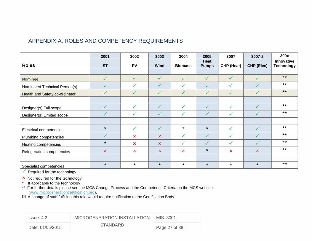
APPENDIX A: ROLES AND COMPETENCY REQUIREMENTS
3001 3002 3003 3004 3005 3007 3007-2 300x
Roles ST PV Wind Biomass Heat
Pumps CHP (Heat) CHP (Elec) Innovative
Technology
Nominee **
Nominated Technical Person(s) **
Health and Safety co-ordinator **
Designer(s) Full scope **
Designer(s) Limited scope **
Electrical competencies * * * **
Plumbing competencies × × **
Heating competencies * × × **
Refrigeration competencies × × × × * × × **
Specialist competencies * * * * * * * **
Required for the technology
× Not required for the technology
* If applicable to the technology
** For further details please see the MCS Change Process and the Competence Criteria on the MCS website: (www.microgenerationcertification.org).
A change of staff fulfilling this role would require notification to the Certification Body.
Issue: 4.2 MICROGENERATION INSTALLATION
STANDARD
MIS: 3001
Date: 01/05/2015 Page 28 of 38
APPENDIX B: MINIMUM REQUIREMENTS - HANDOVER
DOCUMENTATION
At the point at which the Solar Heating System is handed over to the client, the
documentation as detailed below shall be provided and explained to the client:
User Guide (See section B1)
Technical Documents/file including:
o Details of the installation (see section B2)
Note: For installations providing domestic hot water only, a copy of the
Thermal Solar Performance Energy Calculator (TSPEC) could be used to
fulfil this requirement
o An ‘as fitted’ system schematic plan of both plumbing and electrical
systems - detailing all functioning components of the Solar Heating
System up to the point of integration with backup heat source input to
storage vessel
o A completed Commissioning Checklist (see section B3 for minimum
content)
o A Compliance Certificate
o A certificate obtained from the MCS Installation Database, showing that
the installation has been registered with the scheme (to be provided
within 10 working days of the commissioning date)
Note: All though there is some duplication between the compliance certificate and the
commissioning checklist. The compliance certificate confirms both the design and
installation is in accordance to this standard but on the assumption that it may be
completed by office/managerial staff it relies on a declaration by the installation
technician given in the commissioning checklist.
Issue: 4.2 MICROGENERATION INSTALLATION
STANDARD
MIS: 3001
Date: 01/05/2015 Page 29 of 38
B1 Information for the User
Handover information provided to the client shall at minimum include the following user
information:
Where the solar and backup heating share the same hot water cylinder: a
description of how the timing of back-up heating relative to the times of hot water
use should be controlled to achieve maximum energy yield from the Solar
Heating System.
A warning of the risk of bacterial growth within the hot water system and how this
should be controlled.
A note explaining the presence of the temperature controls in the Solar Heating
System and their purpose in preventing scald injuries.
An explanation of any user actions (including frequency) necessary to maintain
lime scale protection devices.
Where the solar heated water is feeding a combination boiler in accordance with
4.3.10: boiler manufacturer’s written instructions for this type of duty.
Information to allow a competent person to undertake the safe de-commissioning
of the Solar Heating System including appropriate warnings.
Details of the methods employed to control damaging effects of freezing, along
with the lowest temperature that these methods protect to. The method and
frequency of maintaining this protection (where required) should also be stated.
All manufacturer documents and warranties relating to any installed equipment.
Any routine maintenance required, such as visual inspection, pump replacement,
and antifreeze replacement.
Issue: 4.2 MICROGENERATION INSTALLATION
STANDARD
MIS: 3001
Date: 01/05/2015 Page 30 of 38
B2 Details of installation
NOTE: The Thermal Solar Performance Energy Calculator (TSPEC) can be used in
place of document B2 where the system provides domestic hot water only.
A document detailing:
Solar Thermal Collector:
Manufacturer’s name
Type and model numbers
Total aperture area
Zero loss Solar Thermal Collector efficiency (ηo) from BS EN 12975
and/or BS EN ISO 9806 test reports
Heat loss coefficient (a1) from BS EN 12975 and/or BS EN ISO 9806 test
reports
Second order heat loss coefficient (a2) from BS EN 12975 and/or BS EN
ISO 9806 test reports
Hot Water Cylinder:
Manufacturer’s name
Type and model number
Total volume (V)
Volume of the dedicated solar volume (Vs)
Surface area of solar heat exchange coil
Where cylinder is replaced, surface area of any backup heat exchange
coils
Maximum working pressure of each heat exchange coil
Solar Controller:
Manufacturer and model
Type
Energy Calculation Parameters:
Where occupancy known:
Issue: 4.2 MICROGENERATION INSTALLATION
STANDARD
MIS: 3001
Date: 01/05/2015 Page 31 of 38
Number of adults in primary residence
Number of children in primary residence
Number of students in residence only outside term time
Other part-time occupants
Where occupancy not known:
Total Floor Area
Panel orientation
Panel tilt from horizontal
SAP region
Overshading factor
Hot water use adjustment factor (from SAP Table H3)
Has the dwelling been classed as water efficient (not more than 125L per
person per day)?
Does the dwelling have a Waste Water Heat Recovery System
(WWHRS)?
Issue: 4.2 MICROGENERATION INSTALLATION
STANDARD
MIS: 3001
Date: 01/05/2015 Page 32 of 38
B3 Commissioning Checklist
The minimum contents of a Solar Commissioning Checklist shall include the following:
Name, address, telephone of the MCS Contractor
Name of technician undertaking commissioning
Collector make, model and serial numbers
Confirmation that Solar Heating System has been checked for leaks
For closed loop Solar Heating Systems: confirmation that system has been
flushed
Confirmation that the insulation is in accordance with this standard
Confirmation that the pump has been tested, produces a flow rate in accordance
with manufacturer’s guidelines, and deactivates under the appropriate
circumstances of either the collector temperature being lower than that of the
solar volume in the cylinder, or where the cylinder maximum temperature setting
has been achieved
Confirmation that all roof penetrations are as per the design and do not adversely
affect the weather tightness of the structure.
Confirm the prescribed MCS label is fixed adjacent to the solar controller
A record of glycol/water % (where glycol is used as a frost protection measure)
A record of system pressure (if pressurised)
A record of gas side pressure on expansion vessel (if fitted)
A record of the settings of the solar controller, dT on, dT off and Tmax
Confirmation that the solar and cylinder sensors (where used) are installed to the
correct locations and secured in place
Type of method used to control scald risk at outlets
Method to control scald risk at outlets
Where an unvented cylinder is installed: confirmation that the solar pump is
connected through a high limit thermostat
Where the solar loop has a pressure relief valve: confirmation that the pressure
relief has been terminated to a suitable location
Where an auto air vent is used: confirmation that the auto air vent has been
isolated from the solar loop once commissioning is completed
Issue: 4.2 MICROGENERATION INSTALLATION
STANDARD
MIS: 3001
Date: 01/05/2015 Page 33 of 38
Where the solar loop is not a drainback: confirmation that the solar loop is fitted
with measures to prevent reverse thermo-syphon
Declaration signed by the installation technician confirming the installation has
been installed to the design and manufacturer’s instructions.
Issue: 4.2 MICROGENERATION INSTALLATION
STANDARD
MIS: 3001
Date: 01/05/2015 Page 34 of 38
APPENDIX C: BUILDING REGULATIONS
In England and Wales, the Building Regulations most immediately relevant to Solar
Heating Systems include (other parts may also apply):
Part A – Structure: ensuring the building, solar collector and fixing system
can withstand the calculated loads for the site
Part B – Fire Safety: ensuring the fire performance of the existing roof
covering is not adversely affected
Part C – Resistance to contaminants and moisture: ensuring the weather
tightness of the structure is not adversely affected
Part G - Sanitation, Hot Water Safety and Water Efficiency
Part L - Conservation of fuel and power
Part P – Electrical Safety
In England and Wales, all work undertaken where the Building Regulations apply must
be notified and notification can take place in several ways, the two principal methods
are:
Submitting a building notice to the relevant Local Authority’s Building Control
department prior to the work commencing;
Notifying the work through a Competent Persons Scheme after the work is
complete.
In Northern Ireland the Building Regulations most immediately relevant to Solar Heating
Systems include (other parts may also apply):
Part C – Site Preparation
Part D – Structure
Part E – Fire Safety
Part F – Conservation of Fuel and Power
In Scotland, all solar water heating installations serving a building must comply with the
requirements of the Building (Scotland) Regulations 2004, as amended, including the
Issue: 4.2 MICROGENERATION INSTALLATION
STANDARD
MIS: 3001
Date: 01/05/2015 Page 35 of 38
functional standards listed in Regulation 9, Schedule 5. Further guidance is available
from : Low carbon equipment and building regulations – A guide to safe and sustainable
construction. Available from :
http://www.scotland.gov.uk/Resource/Doc/217736/0097175.pdf
Issue: 4.2 MICROGENERATION INSTALLATION
STANDARD
MIS: 3001
Date: 01/05/2015 Page 36 of 38
APPENDIX D: LABELLING
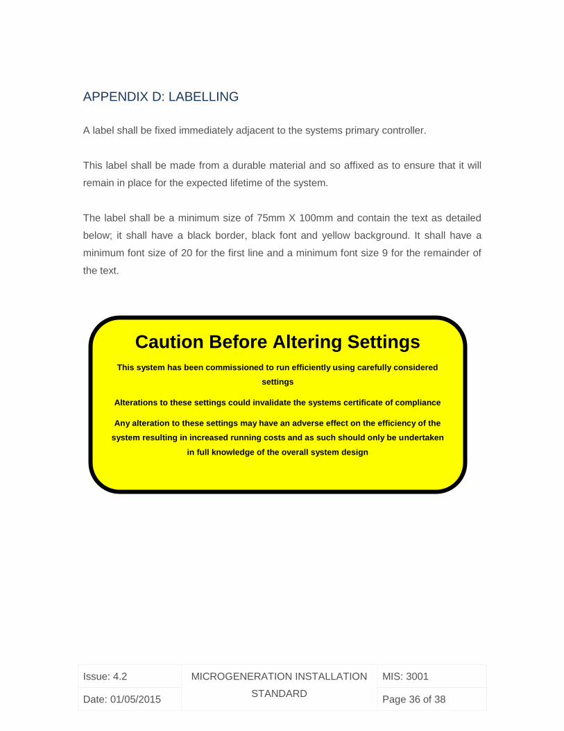
A label shall be fixed immediately adjacent to the systems primary controller.
This label shall be made from a durable material and so affixed as to ensure that it will
remain in place for the expected lifetime of the system.
The label shall be a minimum size of 75mm X 100mm and contain the text as detailed
below; it shall have a black border, black font and yellow background. It shall have a
minimum font size of 20 for the first line and a minimum font size 9 for the remainder of
the text.
Caution Before Altering Settings
This system has been commissioned to run efficiently using carefully considered
settings
Alterations to these settings could invalidate the systems certificate of compliance
Any alteration to these settings may have an adverse effect on the efficiency of the
system resulting in increased running costs and as such should only be undertaken
in full knowledge of the overall system design
Issue: 4.2 MICROGENERATION INSTALLATION
STANDARD
MIS: 3001
Date: 01/05/2015 Page 37 of 38
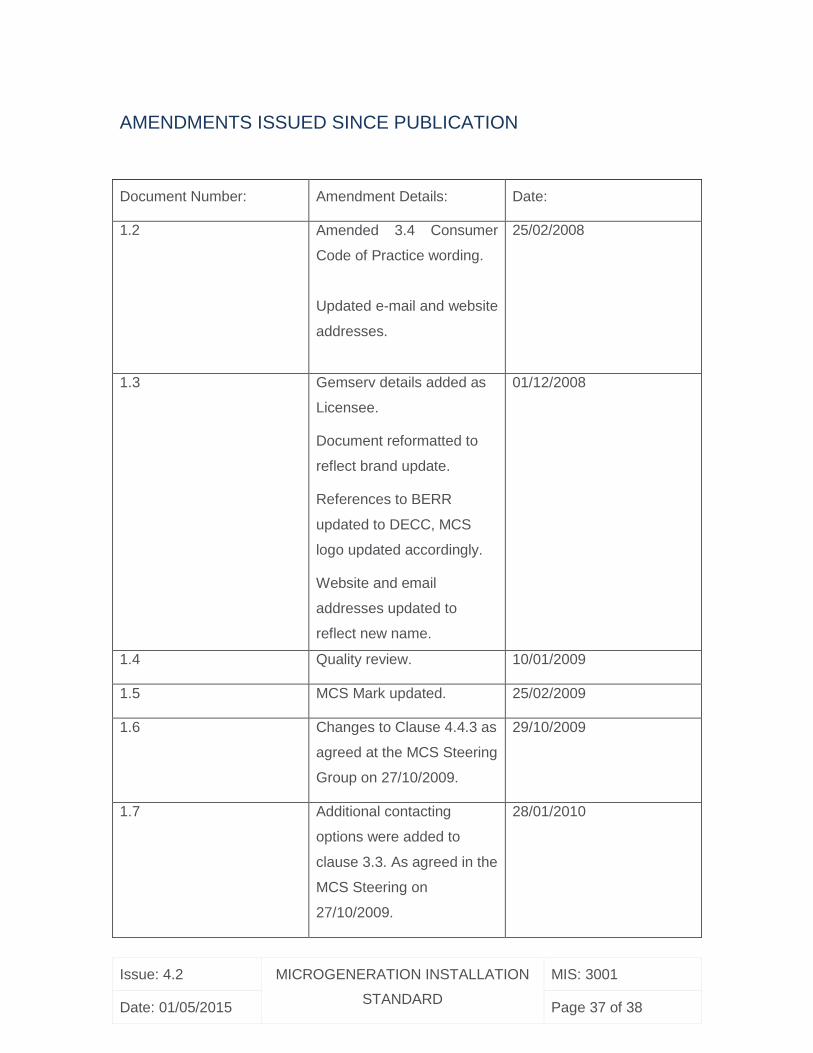
AMENDMENTS ISSUED SINCE PUBLICATION
Document Number: Amendment Details: Date:
1.2 Amended 3.4 Consumer
Code of Practice wording.
Updated e-mail and website
addresses.
25/02/2008
1.3 Gemserv details added as
Licensee.
Document reformatted to
reflect brand update.
References to BERR
updated to DECC, MCS
logo updated accordingly.
Website and email
addresses updated to
reflect new name.
01/12/2008
1.4 Quality review. 10/01/2009
1.5 MCS Mark updated. 25/02/2009
1.6 Changes to Clause 4.4.3 as
agreed at the MCS Steering
Group on 27/10/2009.
29/10/2009
1.7 Additional contacting
options were added to
clause 3.3. As agreed in the
MCS Steering on
27/10/2009.
28/01/2010
Issue: 4.2 MICROGENERATION INSTALLATION
STANDARD
MIS: 3001
Date: 01/05/2015 Page 38 of 38
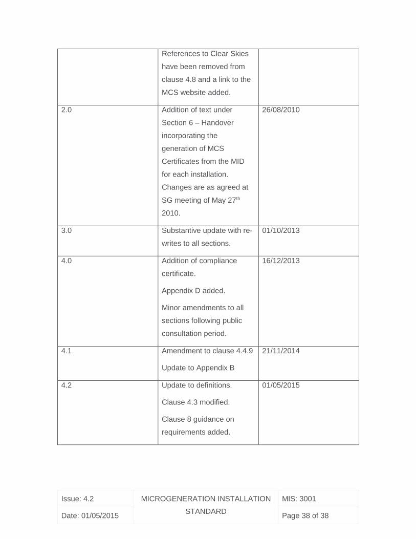
References to Clear Skies
have been removed from
clause 4.8 and a link to the
MCS website added.
2.0 Addition of text under
Section 6 – Handover
incorporating the
generation of MCS
Certificates from the MID
for each installation.
Changes are as agreed at
SG meeting of May 27th
2010.
26/08/2010
3.0 Substantive update with re-
writes to all sections.
01/10/2013
4.0 Addition of compliance
certificate.
Appendix D added.
Minor amendments to all
sections following public
consultation period.
16/12/2013
4.1 Amendment to clause 4.4.9
Update to Appendix B
21/11/2014
4.2 Update to definitions.
Clause 4.3 modified.
Clause 8 guidance on
requirements added.
01/05/2015