Republic of Senegal Preparatory Survey for Mamelles Sea...
394
JR 6R 15-018 Republic of Senegal National Water Company of Senegal (SONES) Republic of Senegal Preparatory Survey for Mamelles Sea Water Desalination Plant Construction Project Final Report October 2015 Japan International Cooperation AgencyInternationale (JICA) Nippon Koei Co., Ltd. CTI Engineering International Co., Ltd (先)
Transcript of Republic of Senegal Preparatory Survey for Mamelles Sea...
JR6R
15-018
Republic of SenegalNational Water Company of Senegal (SONES)
Republic of SenegalPreparatory Survey for
Mamelles Sea Water Desalination PlantConstruction Project
Final Report
October 2015
Japan International Cooperation AgencyInternationale (JICA)
Nippon Koei Co., Ltd.CTI Engineering International Co., Ltd (先)
Republic of SenegalNational Water Company of Senegal (SONES)
Republic of SenegalPreparatory Survey for
Mamelles Sea Water Desalination PlantConstruction Project
Final Report
October 2015
Japan International Cooperation AgencyInternationale (JICA)
Nippon Koei Co., Ltd.CTI Engineering International Co., Ltd
KEUR MOMAR SARR (KMS) WTP
130,000m3/日
NGNITH WTP 45,000m3/日
Well (SEBIKHOATNE) (8,000m3/day) Well (POUT SUD) (21,00m3/day)
Well(POUT KERENE) (5,000m3/day)
Dakar Regionダ
Wells (POUT NORD) (40,00m3/日)
Well(LITTORAL NORD) (32,400m3/日)
Location of Memmeles SWRO Plant
Key Map
[ Legend ] Existing Pipes(ALG1 and ALG2)
WTP to Dakar region
Well to Dakar region
Main pumping stations
Dakar region (target area of the survey)
Target Area of Urbanization MP Study
MECHE Booster Pumping Station (217,808m3/day)
Well(KELLE/KEBEMER/GUEOUL) (24,600m3/日)
CARMEL Booster Pumping Station (241,708m3/day)
New Airport
N
Target Area of the Study-1
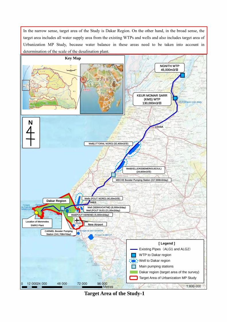
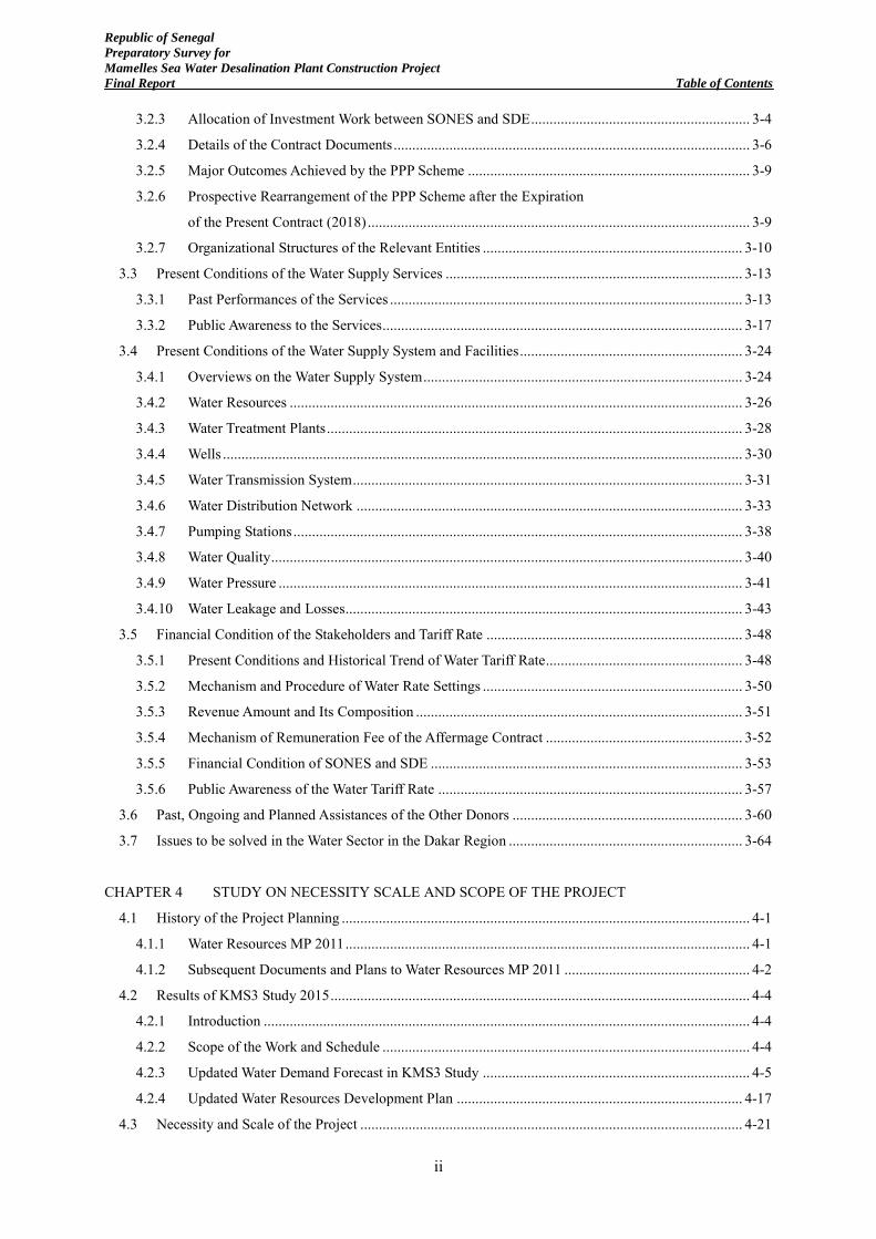
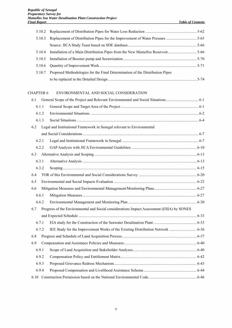
In the narrow sense, target area of the Study is Dakar Region. On the other hand, in the broad sense, the target area includes all water supply area from the existing WTPs and wells and also includes target area of Urbanization MP Study, because water balance in these areas need to be taken into account in determination of the scale of the desalination plant.
LOUGA
THIES
N
Dakar 2 Zone
Rufisque Zone
Dakar 1 Zone
Mamelles Seawter Desalination Plant
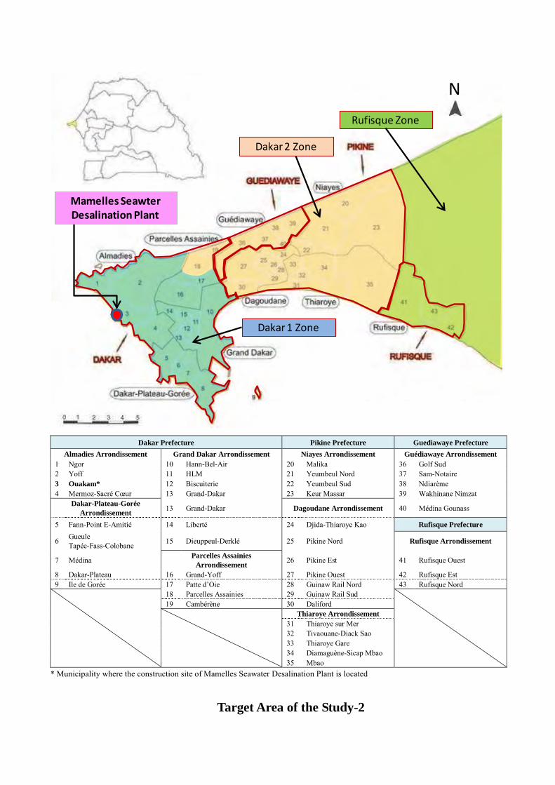
Dakar Prefecture Pikine Prefecture Guediawaye Prefecture
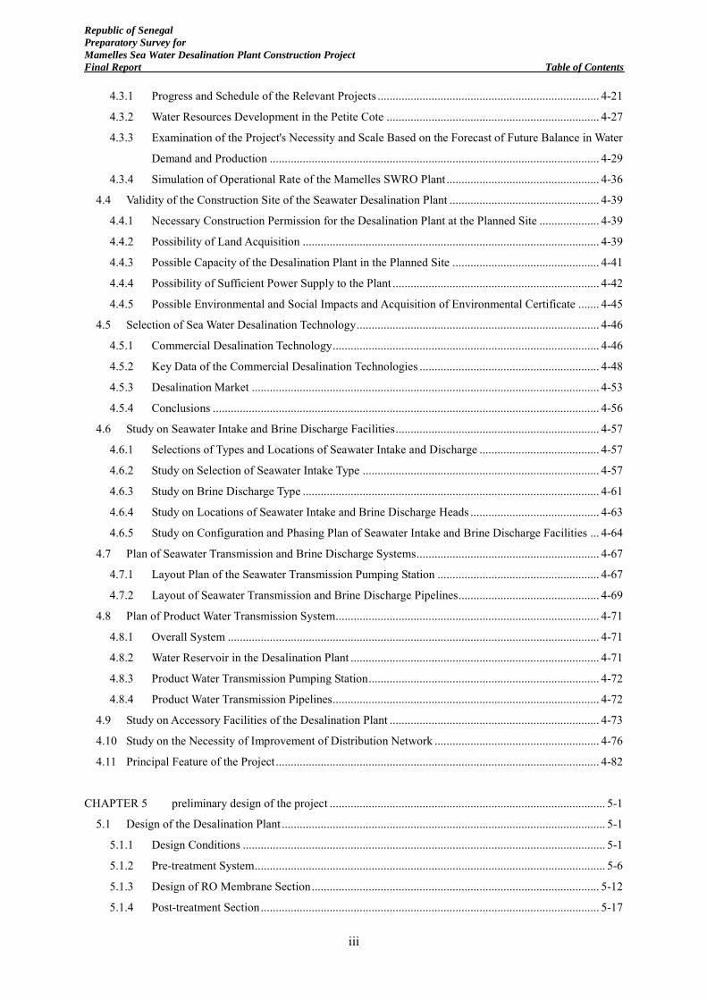
Almadies Arrondissement Grand Dakar Arrondissement Niayes Arrondissement Guédiawaye Arrondissement 1 Ngor 10 Hann-Bel-Air 20 Malika 36 Golf Sud 2 Yoff 11 HLM 21 Yeumbeul Nord 37 Sam-Notaire 3 Ouakam* 12 Biscuiterie 22 Yeumbeul Sud 38 Ndiarème 4 Mermoz-Sacré Cœur 13 Grand-Dakar 23 Keur Massar 39 Wakhinane Nimzat
Dakar-Plateau-Gorée Arrondissement 13 Grand-Dakar Dagoudane Arrondissement 40 Médina Gounass
5 Fann-Point E-Amitié 14 Liberté 24 Djida-Thiaroye Kao Rufisque Prefecture
6 Gueule Tapée-Fass-Colobane 15 Dieuppeul-Derklé 25 Pikine Nord Rufisque Arrondissement
7 Médina Parcelles Assainies Arrondissement 26 Pikine Est 41 Rufisque Ouest
8 Dakar-Plateau 16 Grand-Yoff 27 Pikine Ouest 42 Rufisque Est 9 Ile de Gorée 17 Patte d’Oie 28 Guinaw Rail Nord 43 Rufisque Nord
18 Parcelles Assainies 29 Guinaw Rail Sud
19 Cambérène 30 Daliford
Thiaroye Arrondissement 31 Thiaroye sur Mer 32 Tivaouane-Diack Sao 33 Thiaroye Gare 34 Diamaguène-Sicap Mbao 35 Mbao
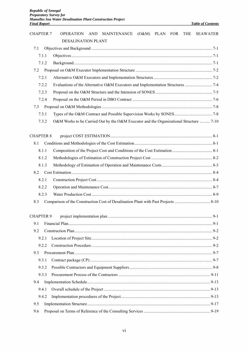
* Municipality where the construction site of Mamelles Seawater Desalination Plant is located
Target Area of the Study-2
Republic of Senegal
Preparatory Survey for
Mamelles Sea Water Desalination Plant Construction Project
Final Report Table of Contents
i
Republic of Senegal
Preparatory Survey for Mamelles Sea Water Desalination Plant Construction Project
Final Report
Table of Contents
CHAPTER 1 INTRODUCTION
1.1 Background of the Study ........................................................................................................................ 1-1
1.2 Objectives, Scope and Target Area of the Study .................................................................................... 1-3
1.2.1 Objectives ...................................................................................................................................... 1-3
1.2.2 Scope ............................................................................................................................................. 1-3
1.2.3 Target Area .................................................................................................................................... 1-3
1.3 Schedule, Progress and Way Forward of the Study ................................................................................ 1-4
CHAPTER 2 present CONDITIONS of the target area of the study ............................................................ 2-1
2.1 Social Conditions ................................................................................................................................... 2-1
2.1.1 Politics, Public Administration and Administrative Boundaries .................................................... 2-1
2.1.2 Population ...................................................................................................................................... 2-3
2.1.3 Economy and Industry ................................................................................................................... 2-3
2.1.4 Public Health ................................................................................................................................. 2-5
2.2 Natural Conditions ................................................................................................................................. 2-6
2.2.1 Weather, Climate and Climate Change .......................................................................................... 2-6
2.2.2 Topography and Geology .............................................................................................................. 2-6
2.2.3 Flora and Fauna ............................................................................................................................. 2-8
2.3 Infrastructure Development ................................................................................................................. 2-10
2.3.1 Transportation .............................................................................................................................. 2-10
2.3.2 Power Supply............................................................................................................................... 2-10
2.3.3 Sewage and Sanitation ................................................................................................................. 2-11
2.3.4 Solid Waste Management ............................................................................................................ 2-12
2.4 Natural Condition Surveys ................................................................................................................... 2-14
2.4.1 Survey Items and Locations ........................................................................................................ 2-14
2.4.2 Survey Results ............................................................................................................................. 2-14
CHAPTER 3 PREsent situation of the water sector in the target area ....................................................... 3-1
3.1 National Policies and Legal Systems in the Water Sector ...................................................................... 3-1
3.1.1 National Policies ............................................................................................................................ 3-1
3.1.2 Fundamental Law and Contracts in the Water Sector .................................................................... 3-1
3.2 The Current PPP Scheme in the Urban Water Supply Sector ................................................................. 3-2
3.2.1 Background of the Introduction of Public-Private Partnership Scheme
to the Urban Water Supply Sector ................................................................................................. 3-2
3.2.2 Implementation Structure under the Affermage Scheme in Senegal ............................................. 3-3
Republic of Senegal
Preparatory Survey for
Mamelles Sea Water Desalination Plant Construction Project
Final Report Table of Contents
ii
3.2.3 Allocation of Investment Work between SONES and SDE ........................................................... 3-4
3.2.4 Details of the Contract Documents ................................................................................................ 3-6
3.2.5 Major Outcomes Achieved by the PPP Scheme ............................................................................ 3-9
3.2.6 Prospective Rearrangement of the PPP Scheme after the Expiration
of the Present Contract (2018) ....................................................................................................... 3-9
3.2.7 Organizational Structures of the Relevant Entities ...................................................................... 3-10
3.3 Present Conditions of the Water Supply Services ................................................................................ 3-13
3.3.1 Past Performances of the Services ............................................................................................... 3-13
3.3.2 Public Awareness to the Services ................................................................................................. 3-17
3.4 Present Conditions of the Water Supply System and Facilities ............................................................ 3-24
3.4.1 Overviews on the Water Supply System ...................................................................................... 3-24
3.4.2 Water Resources .......................................................................................................................... 3-26
3.4.3 Water Treatment Plants ................................................................................................................ 3-28
3.4.4 Wells ............................................................................................................................................ 3-30
3.4.5 Water Transmission System ......................................................................................................... 3-31
3.4.6 Water Distribution Network ........................................................................................................ 3-33
3.4.7 Pumping Stations ......................................................................................................................... 3-38
3.4.8 Water Quality ............................................................................................................................... 3-40
3.4.9 Water Pressure ............................................................................................................................. 3-41
3.4.10 Water Leakage and Losses ........................................................................................................... 3-43
3.5 Financial Condition of the Stakeholders and Tariff Rate ..................................................................... 3-48
3.5.1 Present Conditions and Historical Trend of Water Tariff Rate..................................................... 3-48
3.5.2 Mechanism and Procedure of Water Rate Settings ...................................................................... 3-50
3.5.3 Revenue Amount and Its Composition ........................................................................................ 3-51
3.5.4 Mechanism of Remuneration Fee of the Affermage Contract ..................................................... 3-52
3.5.5 Financial Condition of SONES and SDE .................................................................................... 3-53
3.5.6 Public Awareness of the Water Tariff Rate .................................................................................. 3-57
3.6 Past, Ongoing and Planned Assistances of the Other Donors .............................................................. 3-60
3.7 Issues to be solved in the Water Sector in the Dakar Region ............................................................... 3-64
CHAPTER 4 STUDY ON NECESSITY SCALE AND SCOPE OF THE PROJECT
4.1 History of the Project Planning .............................................................................................................. 4-1
4.1.1 Water Resources MP 2011 ............................................................................................................. 4-1
4.1.2 Subsequent Documents and Plans to Water Resources MP 2011 .................................................. 4-2
4.2 Results of KMS3 Study 2015 ................................................................................................................. 4-4
4.2.1 Introduction ................................................................................................................................... 4-4
4.2.2 Scope of the Work and Schedule ................................................................................................... 4-4
4.2.3 Updated Water Demand Forecast in KMS3 Study ........................................................................ 4-5
4.2.4 Updated Water Resources Development Plan ............................................................................. 4-17
4.3 Necessity and Scale of the Project ....................................................................................................... 4-21
Republic of Senegal
Preparatory Survey for
Mamelles Sea Water Desalination Plant Construction Project
Final Report Table of Contents
iii
4.3.1 Progress and Schedule of the Relevant Projects .......................................................................... 4-21
4.3.2 Water Resources Development in the Petite Cote ....................................................................... 4-27
4.3.3 Examination of the Project's Necessity and Scale Based on the Forecast of Future Balance in Water
Demand and Production .............................................................................................................. 4-29
4.3.4 Simulation of Operational Rate of the Mamelles SWRO Plant ................................................... 4-36
4.4 Validity of the Construction Site of the Seawater Desalination Plant .................................................. 4-39
4.4.1 Necessary Construction Permission for the Desalination Plant at the Planned Site .................... 4-39
4.4.2 Possibility of Land Acquisition ................................................................................................... 4-39
4.4.3 Possible Capacity of the Desalination Plant in the Planned Site ................................................. 4-41
4.4.4 Possibility of Sufficient Power Supply to the Plant ..................................................................... 4-42
4.4.5 Possible Environmental and Social Impacts and Acquisition of Environmental Certificate ....... 4-45
4.5 Selection of Sea Water Desalination Technology ................................................................................. 4-46
4.5.1 Commercial Desalination Technology ......................................................................................... 4-46
4.5.2 Key Data of the Commercial Desalination Technologies ............................................................ 4-48
4.5.3 Desalination Market .................................................................................................................... 4-53
4.5.4 Conclusions ................................................................................................................................. 4-56
4.6 Study on Seawater Intake and Brine Discharge Facilities .................................................................... 4-57
4.6.1 Selections of Types and Locations of Seawater Intake and Discharge ........................................ 4-57
4.6.2 Study on Selection of Seawater Intake Type ............................................................................... 4-57
4.6.3 Study on Brine Discharge Type ................................................................................................... 4-61
4.6.4 Study on Locations of Seawater Intake and Brine Discharge Heads ........................................... 4-63
4.6.5 Study on Configuration and Phasing Plan of Seawater Intake and Brine Discharge Facilities ... 4-64
4.7 Plan of Seawater Transmission and Brine Discharge Systems ............................................................. 4-67
4.7.1 Layout Plan of the Seawater Transmission Pumping Station ...................................................... 4-67
4.7.2 Layout of Seawater Transmission and Brine Discharge Pipelines ............................................... 4-69
4.8 Plan of Product Water Transmission System........................................................................................ 4-71
4.8.1 Overall System ............................................................................................................................ 4-71
4.8.2 Water Reservoir in the Desalination Plant ................................................................................... 4-71
4.8.3 Product Water Transmission Pumping Station ............................................................................. 4-72
4.8.4 Product Water Transmission Pipelines ......................................................................................... 4-72
4.9 Study on Accessory Facilities of the Desalination Plant ...................................................................... 4-73
4.10 Study on the Necessity of Improvement of Distribution Network ....................................................... 4-76
4.11 Principal Feature of the Project ............................................................................................................ 4-82
CHAPTER 5 preliminary design of the project ............................................................................................ 5-1
5.1 Design of the Desalination Plant ............................................................................................................ 5-1
5.1.1 Design Conditions ......................................................................................................................... 5-1
5.1.2 Pre-treatment System ..................................................................................................................... 5-6
5.1.3 Design of RO Membrane Section ................................................................................................ 5-12
5.1.4 Post-treatment Section ................................................................................................................. 5-17
Republic of Senegal
Preparatory Survey for
Mamelles Sea Water Desalination Plant Construction Project
Final Report Table of Contents
iv
5.1.5 Wastewater treatment and disposal systems ................................................................................ 5-19
5.1.6 Chemical storage ......................................................................................................................... 5-20
5.1.7 Control and Instrumentation ........................................................................................................ 5-21
5.1.8 Consideration of Japanese Technologies and Products ................................................................ 5-22
5.2 Design of Seawater Intake Facility ...................................................................................................... 5-25
5.2.1 Design Conditions ....................................................................................................................... 5-25
5.2.2 Seawater Intake Head .................................................................................................................. 5-25
5.2.3 Seawater Intake Pipe ................................................................................................................... 5-26
5.2.4 Chlorine Dosing Pipe................................................................................................................... 5-27
5.3 Design of the Seawater Transmission Pumping Station ....................................................................... 5-28
5.3.1 Design Conditions ....................................................................................................................... 5-28
5.3.2 General Layout ............................................................................................................................ 5-28
5.3.3 Facility Design............................................................................................................................. 5-29
5.3.4 Land Development Design .......................................................................................................... 5-35
5.4 Design of the Seawater Transmission Pipelines ................................................................................... 5-37
5.4.1 Design Conditions ....................................................................................................................... 5-37
5.4.2 Pipeline Design ............................................................................................................................ 5-37
5.5 Design of the Brine Discharge Pipeline ............................................................................................... 5-40
5.5.1 Design Conditions ....................................................................................................................... 5-40
5.5.2 Pipeline Design ............................................................................................................................ 5-40
5.6 Design of Brine Discharge Facility ...................................................................................................... 5-42
5.6.1 Design Conditions ....................................................................................................................... 5-42
5.6.2 Brine Diffusion Analysis ............................................................................................................. 5-42
5.6.3 Brine Discharge Pipe ................................................................................................................... 5-46
5.6.4 Brine Discharge Head .................................................................................................................. 5-47
5.7 Design of the Product Water Transmission Pumping Station ............................................................... 5-48
5.7.1 Design Conditions ....................................................................................................................... 5-48
5.7.2 General Layout ............................................................................................................................ 5-49
5.7.3 Facilities Design .......................................................................................................................... 5-50
5.8 Design of the Product Water Transmission Pipelines ........................................................................... 5-50
5.8.1 Design Conditions ....................................................................................................................... 5-50
5.8.2 Pipe Design .................................................................................................................................. 5-51
5.8.3 Connection Plan of the Transmission Pipelines with the Mamelles Reservoirs .......................... 5-52
5.9 Design of the Substation ...................................................................................................................... 5-55
5.9.1 Design Conditions ....................................................................................................................... 5-55
5.9.2 Necessary Receiving Power Capacity of 90kV ........................................................................... 5-55
5.9.3 Insulation Type of Substation ...................................................................................................... 5-57
5.9.4 Facilities Design .......................................................................................................................... 5-58
5.10 Design of the Improvement Works of the Existing Distribution Network ........................................... 5-61
5.10.1 Work Items and Concept of the Improvement Works .................................................................. 5-61
Republic of Senegal
Preparatory Survey for
Mamelles Sea Water Desalination Plant Construction Project
Final Report Table of Contents
v
5.10.2 Replacement of Distribution Pipes for Water Loss Reduction .................................................... 5-62
5.10.3 Replacement of Distribution Pipes for the Improvement of Water Pressure ............................... 5-63
Source: JICA Study Team based on SDE database ...................................................................... 5-66
5.10.4 Installation of a Main Distribution Pipes from the New Mamelles Reservoir ............................. 5-66
5.10.5 Installation of Booster pump and Sectorization ........................................................................... 5-70
5.10.6 Quantity of Improvement Work ................................................................................................... 5-71
5.10.7 Proposed Methodologies for the Final Determination of the Distribution Pipes
to be replaced in the Detailed Design .......................................................................................... 5-74
CHAPTER 6 ENVIRONMENTAL AND SOCIAL CONSIDERATION
6.1 General Scope of the Project and Relevant Environmental and Social Situations ................................. 6-1
6.1.1 General Scope and Target Area of the Project ............................................................................... 6-1
6.1.2 Environmental Situations .............................................................................................................. 6-2
6.1.3 Social Situations ............................................................................................................................ 6-4
6.2 Legal and Institutional Framework in Senegal relevant to Environmental
and Social Considerations ...................................................................................................................... 6-7
6.2.1 Legal and Institutional Framework in Senegal .............................................................................. 6-7
6.2.2 GAP Analysis with JICA Environmental Guidelines .................................................................. 6-10
6.3 Alternative Analysis and Scoping ........................................................................................................ 6-13
6.3.1 Alternative Analysis .................................................................................................................... 6-13
6.3.2 Scoping ........................................................................................................................................ 6-15
6.4 TOR of this Environmental and Social Considerations Survey ........................................................... 6-20
6.5 Environmental and Social Impacts Evaluation .................................................................................... 6-22
6.6 Mitigation Measures and Environmental Management/Monitoring Plans ........................................... 6-27
6.6.1 Mitigation Measures .................................................................................................................... 6-27
6.6.2 Environmental Management and Monitoring Plan ...................................................................... 6-30
6.7 Progress of the Environmental and Social considerations Impact Assessment (ESIA) by SONES
and Expected Schedule ........................................................................................................................ 6-33
6.7.1 EIA study for the Construction of the Seawater Desalination Plant ............................................ 6-33
6.7.2 IEE Study for the Improvement Works of the Existing Distribution Network ............................ 6-36
6.8 Progress and Schedule of Land Acquisition Process ............................................................................ 6-37
6.9 Compensation and Assistance Policies and Measures.......................................................................... 6-40
6.9.1 Scope of Land Acquisition and Stakeholder Analyses................................................................. 6-40
6.9.2 Compensation Policy and Entitlement Matrix ............................................................................. 6-42
6.9.3 Proposed Grievance Redress Mechanism .................................................................................... 6-43
6.9.4 Proposed Compensation and Livelihood Assistance Scheme ...................................................... 6-44
6.10 Construction Permission based on the National Environmental Code ................................................. 6-46
Republic of Senegal
Preparatory Survey for
Mamelles Sea Water Desalination Plant Construction Project
Final Report Table of Contents
vi
CHAPTER 7 OPERATION AND MAINTENANCE (O&M) PLAN FOR THE SEAWATER
DESALINATION PLANT
7.1 Objectives and Background ................................................................................................................... 7-1
7.1.1 Objectives ...................................................................................................................................... 7-1
7.1.2 Background.................................................................................................................................... 7-1
7.2 Proposal on O&M Executor Implementation Structure ......................................................................... 7-2
7.2.1 Alternative O&M Executors and Implementation Structures ........................................................ 7-2
7.2.2 Evaluations of the Alternative O&M Executors and Implementation Structures .......................... 7-4
7.2.3 Proposal on the O&M Structure and the Intension of SONES ...................................................... 7-5
7.2.4 Proposal on the O&M Period in DBO Contract ............................................................................ 7-6
7.3 Proposal on O&M Methodologies ......................................................................................................... 7-8
7.3.1 Types of the O&M Contract and Possible Supervision Works by SONES .................................... 7-8
7.3.2 O&M Works to be Carried Out by the O&M Executor and the Organizational Structure .......... 7-10
CHAPTER 8 project COST ESTIMATION ................................................................................................. 8-1
8.1 Conditions and Methodologies of the Cost Estimation .......................................................................... 8-1
8.1.1 Composition of the Project Cost and Conditions of the Cost Estimation ...................................... 8-1
8.1.2 Methodologies of Estimation of Construction Project Cost .......................................................... 8-2
8.1.3 Methodology of Estimation of Operation and Maintenance Costs ................................................ 8-3
8.2 Cost Estimation ...................................................................................................................................... 8-4
8.2.1 Construction Project Cost .............................................................................................................. 8-4
8.2.2 Operation and Maintenance Cost ................................................................................................... 8-7
8.2.3 Water Production Cost ................................................................................................................... 8-9
8.3 Comparison of the Construction Cost of Desalination Plant with Past Projects .................................. 8-10
CHAPTER 9 project implementation plan ................................................................................................... 9-1
9.1 Financial Plan ......................................................................................................................................... 9-1
9.2 Construction Plan ................................................................................................................................... 9-2
9.2.1 Location of Project Site ................................................................................................................... 9-2
9.2.2 Construction Procedure ................................................................................................................... 9-2
9.3 Procurement Plan ................................................................................................................................... 9-7
9.3.1 Contract package (CP) .................................................................................................................... 9-7
9.3.2 Possible Contractors and Equipment Suppliers ............................................................................... 9-8
9.3.3 Procurement Process of the Contractors ....................................................................................... 9-11
9.4 Implementation Schedule ..................................................................................................................... 9-13
9.4.1 Overall schedule of the Project ..................................................................................................... 9-13
9.4.2 Implementation procedures of the Project ..................................................................................... 9-13
9.5 Implementation Structure ..................................................................................................................... 9-17
9.6 Proposal on Terms of Reference of the Consulting Services ............................................................... 9-19
Republic of Senegal
Preparatory Survey for
Mamelles Sea Water Desalination Plant Construction Project
Final Report Table of Contents
vii
CHAPTER 10 Financial and economic analysis........................................................................................... 10-1
10.1 Assumptions ......................................................................................................................................... 10-1
10.1.1 Basic Assumptions ....................................................................................................................... 10-1
10.1.2 Conditions of With Project and Without Project.......................................................................... 10-2
10.1.3 Estimation of Production and Saved Water Amount.................................................................... 10-2
10.2 Financial Analysis ................................................................................................................................ 10-6
10.2.1 Outline of Financial Analysis ...................................................................................................... 10-6
10.2.2 Incremental Revenue by the Project ............................................................................................ 10-7
10.2.3 Cost Estimates ............................................................................................................................. 10-8
10.2.4 Result of Financial Analysis ...................................................................................................... 10-10
10.3 Economic Analysis ............................................................................................................................. 10-12
10.3.1 Outline of economic analysis..................................................................................................... 10-12
10.3.2 Economic Benefit ...................................................................................................................... 10-12
10.3.3 Economic Cost........................................................................................................................... 10-16
10.3.4 Result of Economic Analysis ..................................................................................................... 10-17
10.3.5 Sensitivity Analysis ................................................................................................................... 10-18
10.4 Considerations on Future Water Rate ................................................................................................. 10-20
10.4.1 Outline of Result of Tariff Study by PEPAM project ................................................................ 10-20
10.4.2 Applicability of Future Tariff Increase ...................................................................................... 10-24
CHAPTER 11 PROJECT EVALUATION AND PROPSALS ON INDICATORS FOR
MEASUREMENT OF PROJECT EFFECTS ..................................................................... 11-1
11.1 Project Evaluation ................................................................................................................................ 11-1
11.2 Proposals on Indicators for Measurement of Project Effects ............................................................... 11-4
11.3 Climate Change Adaptation ................................................................................................................. 11-6
11.3.1 Climate Change in the Dakar Region .......................................................................................... 11-6
11.3.2 Climate Change Adaptation in the Water Sector ......................................................................... 11-6
11.3.3 Evaluation of the Project from the Viewpoint of Climate Change Adaptation ............................ 11-7
CHAPTER 12 RECOMMENDATIONS ...................................................................................................... 12-1
12.1 Risks on the Project and the Countermeasures ............................................................................ 12-1
12.2 Recommendations on Possible Cooperation among the Donors for Improvement
of the Water Supply Services in the Dakar Region ...................................................................... 12-2
Exchange Rate (October, 2015)
XOF/US$ = 588.9
JPY/USR = 120.2
JPY/XOF = 0.204
Republic of Senegal
Preparatory Survey for
Mamelles Sea Water Desalination Plant Construction Project
Final Report List of Figures
viii
List of Figures
Figure 1.3.1 Overall Schedule of the Study .................................................................................................... 1-4
Figure 2.1.1 Administrative boundaries of the Dakar Region......................................................................... 2-2
Figure 2.2.1 Temperatures and Precipitations in the Dakar Region ............................................................. 2-6
Figure 2.2.2 Geological map of the Cap Vert Peninsula ................................................................................. 2-8
Figure 2.2.3 Location of the Ecological Importance Areas and the Project Site ............................................. 2-9
Figure 2.3.1 Sewerage System Development Plan in the Master Plan of ONAS ......................................... 2-12
Figure 2.4.1 Survey Location ........................................................................................................................ 2-14
Figure 3.2.1 Senegalese PPP Scheme in the Water Sector .............................................................................. 3-4
Figure 3.2.2 Organizational Structure of SONES (As of February 2015) ..................................................... 3-10
Figure 3.2.3 Organizational Structure of SDE (As of February 2015) .......................................................... 3-11
Figure 3.2.4 Organizational Structure of MHA (As of May 2015) ............................................................... 3-12
Figure 3.3.1 Recent Trend in Water Access and Number of Service Connections in Senegal since 1996 .... 3-15
Figure 3.3.2 Recent Trend in Water Production in Senegal since 1996 ........................................................ 3-15
Figure 3.3.3 Sectors in Dakar 1 Zone ........................................................................................................... 3-19
Figure 3.4.1 Schematic of Water Supply System for the Dakar Region and the ALG Wayside Areas ...... 3-25
Figure 3.4.2 Water Production for the Dakar Region and the ALG Wayside Areas by Water Resource ....... 3-26
Figure 3.4.3 Routes of the Main Transmission Lines ; ALG1, ALG2 and Sebi800 ...................................... 3-32
Figure 3.4.4 Characteristics of the Pipes in ALG1 ........................................................................................ 3-32
Figure 3.4.5 Characteristics of the Pipes in ALG2 ........................................................................................ 3-33
Figure 3.4.6 Characteristics of the Pipes in Sebi800 ..................................................................................... 3-33
Figure 3.4.7 Locations of the Existing Reservoirs/Reservoir Groups in the Dakar Region .......................... 3-35
Figure 3.4.8 Distribution Pipe Length by Age in the Dakar Region ............................................................. 3-37
Figure 3.4.9 Compositions of Pipe Materials in the Dakar Region ............................................................... 3-38
Figure 3.4.10 Distribution of the Frequent Water Deficit Areas due to Low Water Pressure
n the Dakar 1 Zone in 2014 and 2015 ....................................................................................... 3-43
Figure 3.4.11 NRW Volume and Ratio by Zone in the Dakar Region ............................................................ 3-44
Figure 3.4.12 Leakage areas in distribution area of present Mamelles reservoir group and the vicinity ..... 3-46
Figure 3.4.13 Number of Leakages by Sector in 2014 .................................................................................... 3-46
Figure 3.4.14 Composition of Number of Leakages by Pipe Diameter in 2014 ............................................. 3-47
Figure 3.5.1 Average tariff rate and allocation of revenue between SONES and SDE ................................. 3-49
Figure 3.5.2 Historical Trend of Tariff Rate of Domestic and Administration Category .............................. 3-49
Figure 3.5.3 Billed Water Amount ................................................................................................................ 3-51
Figure 3.5.4 Total Revenue of Water and Sanitation Charges without TAX ................................................. 3-52
Figure 4.1.1 Water Resources Development Plan Proposed in Water Resources MP 2011 ............................ 4-1
Figure 4.2.1 Scope and Schedule of ES for KMS3 Project ............................................................................. 4-4
Figure 4.2.2 Results of the Updated Water Demand Forecast in KMS3 Study ............................................... 4-5
Figure 4.2.3 Categorization of Water Produced to Define NRW .................................................................. 4-15
Figure 4.2.4 Future Balance of Water Demand and Production capacity in The KMS3 Study..................... 4-19
Republic of Senegal
Preparatory Survey for
Mamelles Sea Water Desalination Plant Construction Project
Final Report List of Figures
ix
Figure 4.3.1 Locations, Capacities and Completion Years of the Planned Water Production Projects
for the Dakar Region and the ALG Wayside ............................................................................ 4-22
Figure 4.3.2 Expected Schedule by SONES of KMS3 WTP Project ............................................................ 4-24
Figure 4.3.3 Possible Schedule of the Seawater Desalination Project for Petite Cote in the Most
Optimistic Case ......................................................................................................................... 4-27
Figure 4.3.4 Water Resources Development Scenario and the Water Demand Forecast for the Petite
Cote in the Water Resources MP 2011 ...................................................................................... 4-28
Figure 4.3.5 Water Demand and Production Gap in the Without-Project Case ............................................. 4-31
Figure 4.3.6 Water Demand and Production Gap in Case 1 (Mamelles Phase 1: 50,000 m3/day) ................ 4-33
Figure 4.3.7 Water Demand and Production Gap in Case 2 (Mamelles Phase 1: 75,000 m3/day) ................ 4-33
Figure 4.3.8 Water Demand and Production Gap in Case 1
(Mamelles Phase 1: 50,000 m3/day) on Assumption that the Reduction of
Groundwater Extraction will be a half of the Expected Amount by 2024 ................................ 4-35
Figure 4.3.9 Operational Modes of the Mamelles SWRO Plant in Different Water Demand Cases .......... 4-37
Figure 4.3.10 Projected Production Rate of the Mamelles SWRO Plant (Annual Average) ........................... 4-38
Figure 4.3.11 Projected Production Rate of the Mamelles SWRO Plant (on the Daily Maximum
Water Demand Condition) ........................................................................................................ 4-38
Figure 4.4.1 Required Land for the Project ................................................................................................... 4-40
Figure 4.4.2 Necessary Power for Construction and Operation of the Mamelles SWRO Plant.................... 4-42
Figure 4.4.3 High Voltage Network in 2015 ................................................................................................. 4-44
Figure 4.5.1 Principle of Reverse Osmosis Technology ............................................................................... 4-46
Figure 4.5.2 Block Diagram of SWRO Plant ................................................................................................ 4-46
Figure 4.5.3 Working Principle of an MED-TVC Unit Technology ............................................................. 4-47
Figure 4.5.4 Working Principle of an MSF Unit (Once through mode) ........................................................ 4-48
Figure 4.5.5 OPEX for Conventional Desalination Technologies in General Electricity Rate
Condition .................................................................................................................................. 4-52
Figure 4.5.6 OPEX for Conventional Desalination Technologies in Electricity Rate Condition in Senegal 4-52
Figure 4.5.7 Breakdown of Total Online Desalting Capacity ....................................................................... 4-52
Figure 4.5.9 Online Desalination Plants sorted by Technology and Daily capacity ..................................... 4-53
Figure 4.5.8 Cumulative Capacity of the Main Desalination Technologies put Online in
and Outside the GCC Countries ................................................................................................ 4-53
Figure 4.5.10 Contracted capacity from 2006 to October 2014 ...................................................................... 4-55
Figure 4.6.1 Procedure of Selections of Types and Locations of the Seawater Intake
and Brine Discharge............................................................................................................... 4-57
Figure 4.6.2 Classification of Seawater Intake Type ..................................................................................... 4-58
Figure 4.6.3 Classification of Brine Discharge ............................................................................................. 4-61
Figure 4.6.4 Intake and Discharge Points ..................................................................................................... 4-64
Figure 4.7.1 Layout of Seawater Transmission Pumping Station, Seawater Transmission Pipeline
and Effluent Discharge Pipeline ............................................................................................... 4-67
Figure 4.7.2 Layout Plan of Seawater Transmission Pumping Station ......................................................... 4-68
Republic of Senegal
Preparatory Survey for
Mamelles Sea Water Desalination Plant Construction Project
Final Report List of Figures
x
Figure 4.7.3 Necessary Land Area for the Seawater Transmission Pumping Station ................................ 4-69
Figure 4.7.4 Typical Cross Section of the Seawater Transmission and Brine Discharge Pipelines
in the Airport Road Section ...................................................................................................... 4-70
Figure 4.8.1 Product Water Transmission System ......................................................................................... 4-71
Figure 4.9.1 Layout of Turbine Stations for Energy Recovery from the Effluent ......................................... 4-74
Figure 4.10.1 Present and Future Distribution Areas of the New Mamelles Reservoir Group ....................... 4-77
Figure 4.10.2 Composition of Pipe Diameter In Dakar 1 Zone ...................................................................... 4-79
Figure 4.11.1 Layout Plan of Mamelles Seawater Desalination Plant Construction Project .......................... 4-83
Figure 5.1.1 Seawater Temperature in Dakar Region ..................................................................................... 5-2
Figure 5.1.2 Block Diagram of SWRO plant .................................................................................................. 5-4
Figure 5.1.3 Layout Plan of the Mamelles SWRO Plant ................................................................................ 5-5
Figure 5.1.4 General Arrangement of UF Membrane Skid ........................................................................... 5-11
Figure 5.1.5 Specific Power Demand in Relation to Temperature at Different Recovery Ratio ................... 5-13
Figure 5.1.6 Relation of Number of Trains and Power Demand (X axis: Left-temperature,
Right-salinity) ........................................................................................................................... 5-15
Figure 5.1.7 Flow Diagram of Wastewater Collection and Treatment .......................................................... 5-19
Figure 5.1.8 Market Share of RO Membrane Sales for Japanese ................................................................. 5-22
Figure 5.2.1 General Layout of the Seawater Intake Facility ........................................................................ 5-25
Figure 5.2.2 Seawater Intake Head ............................................................................................................... 5-26
Figure 5.2.3 Intake Pipes at Onshore and Offshore (Cross Section) ............................................................. 5-27
Figure 5.2.4 Intake Pipes (Longitudinal Section).......................................................................................... 5-27
Figure 5.3.1 Layout of the Seawater Transmission Pumping Station ........................................................... 5-29
Figure 5.3.2 Layout of Facilities in the Pump House .................................................................................... 5-30
Figure 5.3.3 Pump House Section ................................................................................................................. 5-32
Figure 5.3.4 Layout Plan of Valves ............................................................................................................... 5-32
Figure 5.3.5 Layout of Flow Meter Pit and Air Vessel .................................................................................. 5-33
Figure 5.3.6 Single Line Diagram of Seawater Transmission Pumping Station ........................................... 5-34
Figure 5.3.7 Layout of Electrical Room ........................................................................................................ 5-34
Figure 5.3.8 Plan and Cross Section of the Site of the Seawater Transmission Pumping Station ................. 5-36
Figure 5.4.1 Plan and Profile of the Seawater Transmission Pipelines ......................................................... 5-37
Figure 5.5.1 Plan and Profile of the Brine Discharge Pipeline...................................................................... 5-40
Figure 5.6.1 General Layout of the Brine Discharge Facility ....................................................................... 5-42
Figure 5.6.2 Diffusion Range and Methodologies for the Brine Diffusion Analysis .................................... 5-44
Figure 5.6.3 Analysis result in Near-field (Left; Salinity distribution and Right; Velocity distribution) ...... 5-44
Figure 5.6.4 Analysis Result of the Brine Diffusion Range .......................................................................... 5-46
Figure 5.6.5 Brine Discharge Pipe at Onshore (Left) and Offshore (Right) ................................................. 5-47
Figure 5.6.6 Brine Discharge Pipe (Longitudinal Section) ........................................................................... 5-47
Figure 5.6.7 Brine Discharge Head (Frontage) ............................................................................................. 5-48
Figure 5.6.8 Brine Discharge Head (Longitudinal Section) .......................................................................... 5-48
Figure 5.7.1 Layout of the Product Water Transmission Pumping Station ................................................... 5-49
Republic of Senegal
Preparatory Survey for
Mamelles Sea Water Desalination Plant Construction Project
Final Report List of Figures
xi
Figure 5.8.1 Plan and Profile of the Product Water Transmission Pipelines ................................................. 5-52
Figure 5.8.2 Connection Plan of the to the Existing Transmission System ................................................... 5-53
Figure 5.8.3 Synoptic Diagram of the Connection Plan of the Product Water Transmission
Pipelines with the Existing Inflow Pipes to the Mamelles Reservoirs ...................................... 5-54
Figure 5.9.1 Location of Substation .............................................................................................................. 5-55
Figure 5.9.2 Single Line Diagram of Substation ........................................................................................... 5-58
Figure 5.9.3 Layout of the Substation ........................................................................................................... 5-59
Figure 5.9.4 Cable pit for 90 kV Cables ....................................................................................................... 5-60
Figure 5.9.5 Cable Pit for 30 kV Cables ....................................................................................................... 5-60
Figure 5.10.1 Correlation between Occupation Ratios of the Old Distribution Pipes
(Age≥40 Years) and the NRW Ratios by Zone in Dakar Region .............................................. 5-62
Figure 5.10.2 Correlation between Occupation Ratios of the Old Distribution Pipes
(Age≥40 Years) and ILI Values by Zone in Dakar Region ..................................................... 5-62
Figure 5.10.3 Typical Section of Service Connection for Renewal ................................................................ 5-63
Figure 5.10.4 Accumulated Ratio of Pipe length against Total length in the Dakar 1, Dakar 2,
Rufisque, Manila, Tokyo and Osaka ......................................................................................... 5-64
Figure 5.10.5 Layout of the Existing DN 400 and the Plan of the Additional Main Distribution Pipeline ..... 5-66
Figure 5.10.6 Layout of the Existing DN 600 ................................................................................................. 5-68
Figure 5.10.7 Areas with Chronic Low Water Pressure with Contours ........................................................ 5-70
Figure 5.10.8 Concept of the Sectorization ..................................................................................................... 5-71
Figure 5.10.9 Calculation of the Total Replacement Length of the Distribution Pipes ................................... 5-73
Figure 5.10.10 Proposed Methodologies in the Detailed Design to Determine the Distribution
Pipes to be Replaced ................................................................................................................. 5-76
Figure 6.1.1 Project Area ................................................................................................................................ 6-2
Figure 6.1.2 Location of the Ecological Importance Areas and the Project Area in the Dakar Region .......... 6-3
Figure 6.2.1 Organization Chart of DEEC ...................................................................................................... 6-9
Figure 6.6.1 Proposed Organization Structure of the Environmental and Social Monitoring
for the Project ........................................................................................................................... 6-31
Figure 6.7.1 General EIA Procedure until Issuance of ECC in Senegal ....................................................... 6-34
Figure 6.7.2 Procedure of IEE....................................................................................................................... 6-36
Figure 6.8.1 Land Acquisition Process for the Project .................................................................................. 6-39
Figure 6.9.1 Proposed Monitoring Organizations for Land Acquisition and
Necessary Livelihood Assistance .............................................................................................. 6-44
Figure 6.10.1 Procedure for the Construction Permission based on the Article L 13
of the National Environmental Code ........................................................................................ 6-47
Figure 7.2.1 Alternative Plans of the O&M Executors and Implementation Structure
of the Seawater Desalination Plant ............................................................................................. 7-3
Figure 7.2.2 Final Alternative Plans of the O&M Executors and Implementation Structure
of the Seawater Desalination Plant in Consideration of a possible Future Shift ......................... 7-6
Figure 7.3.1 Flows in O&M Works in the Desalination Plant....................................................................... 7-10
Republic of Senegal
Preparatory Survey for
Mamelles Sea Water Desalination Plant Construction Project
Final Report List of Figures
xii
Figure 7.3.2 Suggested Organizational Structure of the O&M Executor ...................................................... 7-13
Figure 8.3.1 Comparison of the Construction Cost of Seawater Desalination Facility ................................. 8-10
Figure 9.2.1 Project Location .......................................................................................................................... 9-2
Figure 9.2.2 General Layout of Seawater Desalination Plant ......................................................................... 9-3
Figure 9.2.3 Target Area of the Improvement Works of the Existing Distribution Network .......................... 9-4
Figure 9.3.1 Top 20 EPC Contractors of Seawater Desalination Plant and their Contract Capacity
in 2000-2011 ............................................................................................................................... 9-8
Figure 9.4.1 Overall Implementation Schedule of Mamelles Seawater Desalination Plant
Development Project ................................................................................................................ 9-16
Figure 9.5.1 Implementation Structure of the Project ................................................................................... 9-18
Figure 10.1.1 Predicted Production by Water Resource in Case Future Expansions of KMS2
and the Mamelles SWRO Plant are not Considered ................................................................. 10-3
Figure 10.1.2 Assumed NRW Rate and Saved Water Amount by the Project................................................. 10-4
Figure 10.1.3 Estimated Production Amount and Saved Water Amount for Financial
and Economic Analyses ............................................................................................................ 10-5
Figure 10.2.1 Estimated Incremental Revenue Amount .................................................................................. 10-8
Figure 10.2.2 Financial Cost of the Project ................................................................................................... 10-10
Figure 10.3.1 Economic Benefits of the Project ........................................................................................... 10-16
Figure 10.3.2 Economic Costs of the Project ................................................................................................ 10-17
Figure 11.3.2 Changes of Precipitation in Senegal ......................................................................................... 11-6
Figure 11.3.1 Observed and simulated variations in past and projected future annual average
temperature over East African Community–Intergovernmental Authority on Development .... 11-6
Republic of Senegal
Preparatory Survey for
Mamelles Sea Water Desalination Plant Construction Project
Final Report List of Tables
xiii
List of Tables
Table 1.1.1 Water Production Facilities proposed in Water Resources MP 2011 .......................................... 1-1
Table 1.2.1 Scope of the Study ...................................................................................................................... 1-3
Table 2.1.1 Administrative Distribution of the Dakar Region ....................................................................... 2-2
Table 2.1.2 Population and Growth Ratio in the Dakar Region from 1976 to 2013 ...................................... 2-3
Table 2.1.3 Population Density and Other Indicators of the Dakar Region and Senegal in 2013 ................. 2-3
Table 2.1.4 Annual Growth Rate and GDP per Capita in Senegal ................................................................ 2-4
Table 2.1.5 Production Amount by Subsector (F.CFA Billion)...................................................................... 2-4
Table 2.1.6 Health Indicators in Senegal ....................................................................................................... 2-5
Table 2.3.1 Power Demand and supply in Senegal...................................................................................... 2-11
Table 2.3.2 List of Wastewater Treatment Plant in the Dakar Region ......................................................... 2-12
Table 2.4.1 Survey Profiles ......................................................................................................................... 2-14
Table 3.1.1 Fundamental Law and Contracts in the Urban Water Supply Sector .......................................... 3-1
Table 3.2.1 General PPP Schemes applied to Water Supply Services ........................................................... 3-2
Table 3.2.2 Fundamental Responsibilities of the Water Supply Entities
under the Senegalese PPP Scheme.............................................................................................. 3-4
Table 3.2.3 Allocation of Investment between SONES and SDE ................................................................. 3-5
Table 3.2.4 Target and Realization of Renewal Work by SONES ................................................................. 3-6
Table 3.2.5 Target and Realization of Renewal Work by SDE ...................................................................... 3-6
Table 3.2.6 Performance Indicators between MHA & SONES ..................................................................... 3-7
Table 3.2.7 List of Roles on SONES & SDE (Setting on Renewal and Repair Works) ................................ 3-8
Table 3.2.8 Shareholder Composition of SDE ............................................................................................. 3-11
Table 3.3.1 General Parameters of Water Supply Services in Senegal and the Dakar Region .................... 3-13
Table 3.3.2 Performance Results of SDE Based on the Performance Indicators ......................................... 3-14
Table 3.3.3 Satisfaction Rates to the Water Supply Services by Question Category
in the Customer Satisfaction Survey by SONES in 2012 ......................................................... 3-18
Table 3.3.4 Overall Satisfaction Rates to the Water Supply Services by Area
in the Customer Satisfaction Survey by SONES in 2012 ......................................................... 3-18
Table 3.3.5 Dissatisfaction Reasons to the Water Supply Service Level in the Customer Satisfaction Survey
by SONES in 2012.................................................................................................................... 3-19
Table 3.3.6 Sample Distribution of the Social Baseline Survey .................................................................. 3-20
Table 3.3.7 Household Satisfaction ............................................................................................................. 3-20
Table 3.3.8 Availability of SONES Water ................................................................................................... 3-21
Table 3.3.9 SONES Water Pressure ............................................................................................................. 3-22
Table 3.3.10 Bad Taste of SONES Water ...................................................................................................... 3-22
Table 3.3.11 Bad Color of SONES Water ..................................................................................................... 3-23
Table 3.3.12 Bad Smell of SONES Water ..................................................................................................... 3-23
Table 3.4.1 Outlines of the Main Facilities in the Water Supply System for the Dakar Region
and the ALG Wayside Areas ..................................................................................................... 3-26
Republic of Senegal
Preparatory Survey for
Mamelles Sea Water Desalination Plant Construction Project
Final Report List of Tables
xiv
Table 3.4.2 Current Water Resources for the Dakar Region and the ALG Wayside Areas .......................... 3-27
Table 3.4.3 Operational Conditions of the Existing Wells ........................................................................... 3-30
Table 3.4.4 Distribution Reservoirs in the Dakar Region ............................................................................ 3-36
Table 3.4.5 Distribution Pipe Length by Area and Age in The Dakar Region(as of year 2013) .................. 3-36
Table 3.4.6 Material of Pipe by Zone (Unit: km) ........................................................................................ 3-37
Table 3.4.7 Maintenance Ability and Specification in the Existing Main Pumping Stations ...................... 3-39
Table 3.4.8 Existing Electrical in the Major Pumping Stations ................................................................... 3-39
Table 3.4.9 Voltage Categories of Electric Power Lines supplied by SENELEC ........................................ 3-40
Table 3.4.10 Linear Loss Index by Zone ....................................................................................................... 3-45
Table 3.5.1 Present Water and Sanitation Tariff Rate of SONES ................................................................ 3-48
Table 3.5.2 Approval Procedure of Water Tariff Change ............................................................................ 3-50
Table 3.5.3 Billed Water Amount ................................................................................................................ 3-51
Table 3.5.4 Total Revenue of Water and Sanitation Charge without TAX .................................................. 3-52
Table 3.5.5 Financial Statements of SONES ............................................................................................... 3-55
Table 3.5.6 Financial Statements of SDE .................................................................................................... 3-56
Table 3.5.7 Category Wise Satisfaction Level on the Tariff ........................................................................ 3-57
Table 3.5.8 Comparison of Present Tariff and WTP .................................................................................... 3-58
Table 3.5.9 Willingness to Pay of Water Users in addition to the Present Tariff Level
by the Tariff Study 2015 ........................................................................................................... 3-58
Table 3.5.10 Result of Social Condition Survey on WTP for Improved Water Supply Service .................... 3-59
Table 3.6.1 Outlines of the Water Supply Projects of SONES Financed or to be Financed
by the Other Donors (as of October 2105) ................................................................................ 3-63
Table 4.1.1 History in the Plan of the Mamelles SWRO Plant ...................................................................... 4-3
Table 4.2.1 Summary of the Different Assumptions in the Optional Scenarios of Water Demand Forecast in
KMS3 Study ............................................................................................................................... 4-6
Table 4.2.2 Directions in the update of the basic conditions for the Water Demand Forecast in KMS3 Study
.................................................................................................................................................... 4-7
Table 4.2.3 Update of population in the base year of the Water Demand Forecast ....................................... 4-7
Table 4.2.4 Update of Population in 2013 in the Target Area ........................................................................ 4-8
Table 4.2.5 Population Growth Ratios in Water Resources MP 2011 ............................................................ 4-8
Table 4.2.6 Update of Population Growth Ratio in KMS3 Study ................................................................. 4-9
Table 4.2.7 Population Growth Ratios Projected in Project for Updating Dakar Urbanization Master Plan by
the Horizon 2025 by JICA .......................................................................................................... 4-9
Table 4.2.8 Coverage of the Water Supply Services and Service Connections ........................................... 4-10
Table 4.2.9 Update of the Assumptions in Service Coverage ...................................................................... 4-10
Table 4.2.10 Actual Unit Water Consumptions in 2008 and 2013................................................................. 4-11
Table 4.2.11 Update of Population Growth Ratio in KMS3 Study ............................................................... 4-11
Table 4.2.12 Comparison of the Combined Unit Water Consumptions for Domestic Purposes and for the All
purposes in Dakar Region ......................................................................................................... 4-13
Table 4.2.13 Update of the Assumptions in Peak Factor ............................................................................... 4-14
Republic of Senegal
Preparatory Survey for
Mamelles Sea Water Desalination Plant Construction Project
Final Report List of Tables
xv
Table 4.2.14 Update of the Assumptions in Network Efficiency................................................................... 4-15
Table 4.2.15 Existing Water Production in KMS3 Study 2015 and the Latest Information from SONES/SDE
.................................................................................................................................................. 4-17
Table 4.2.16 Planned Additional Capacity and Assumed Reduction of Water Production in KMS3 Study .. 4-18
Table 4.2.17 Future Gap between Water Demand and Production Capacity in The KMS3 Study in the Case of
Water Demand Scenario A ........................................................................................................ 4-19
Table 4.3.1 The First Phase of Emergency Wells Development Plan by June 2015 .................................... 4-23
Table 4.3.2 The Second Phase of Emergency Wells Development Plan by December 2015 ...................... 4-23
Table 4.3.3 Optional Plans of the KMS3 WTP Project ............................................................................... 4-24
Table 4.3.4 Assumptions in Water Demand and Production Gap Analysis in Without-Project Case ....... 4-30
Table 4.3.5 Assumptions in the Examination of the Project's Necessity and Capacity ............................... 4-32
Table 4.4.1 Land Areas for the Mamelles SWRO Plant Construction Project ............................................ 4-39
Table 4.4.2 Examination of Area Requirement of the Mamelles Seawater Desalination Plant ................... 4-41
Table 4.4.3 Agreed Receiving Power for the Plant between SENELEC and JICA Study Team ................. 4-42
Table 4.4.4 Planned Projects of IPP (Independent Power Production) by Conventional Energy ................ 4-43
Table4.4.5 Planned Projects of IPP (Independent Power Production) by Renewable Energ ...................... 4-44
Table 4.5.1 Key Design Data of the Commercial Desalination Technologies ............................................. 4-49
Table4.5.2 Key Energy Data of the Commercial Desalination Technologies ............................................. 4-50
Table 4.5.3 Specific CAPEX in USD / (m³/day) ......................................................................................... 4-50
Table 4.6.1 Conceptual Diagrams of Direct Seawater Intakes .................................................................... 4-58
Table 4.6.2 Conceptual Diagrams of Indirect Seawater Intakes .................................................................. 4-59
Table 4.6.3 Comparison of Seawater Intake Type ....................................................................................... 4-60
Table 4.6.4 Conceptual Diagram of Brine discharge by Direct discharge type ........................................... 4-61
Table 4.6.5 Conceptual Diagram of Brine discharge by Indirect discharge type ......................................... 4-62
Table 4.6.6 Comparison of Brine discharge types ....................................................................................... 4-63
Table 4.9.1 Influences on the Desalination Plant Given by Installation of the Turbine............................... 4-74
Table 4.10.1 Flow Rates in the Main Distribution Pipelines of the New Mamelles Reservoirs in 2014 .... 4-79
Table 4.10.2 Length of Improvement of Distribution Pipe ............................................................................ 4-80
Table 4.11.1 General Scope of the Mamelles Seawater Desalination Plant Construction Project ................. 4-82
Table 5.1.1 Capacity of the Mamelles SWRO Plant ...................................................................................... 5-1
Table 5.1.2 Design Conditions of the Mamelles SWRO Plant on Water Quality .......................................... 5-2
Table 5.1.3 List of the buildings of the Plant ................................................................................................. 5-6
Table 5.1.4 Comparison of Pre-treatment Process ......................................................................................... 5-9
Table 5.1.5 Operational Expenditure ........................................................................................................... 5-10
Table 5.1.6 Characteristics of UF Membrane .............................................................................................. 5-10
Table 5.1.7 Projection of Boron Density in the Product Water with One Pass
of the RO Membrane Filtration ................................................................................................ 5-14
Table 5.1.8 Comparison between two types of Isobaric ERS ...................................................................... 5-17
Table 5.1.9 Water Quality Items for Monitoring ......................................................................................... 5-19
Table 5.1.10 Chemicals and their Consumption Volumes used in the Mamelles SWRO Plant ..................... 5-21
Republic of Senegal
Preparatory Survey for
Mamelles Sea Water Desalination Plant Construction Project
Final Report List of Tables
xvi
Table 5.1.11 Water Quality Items for Monitoring and Control ..................................................................... 5-21
Table 5.2.1 Setting of Tidal Level ............................................................................................................... 5-25
Table 5.3.1 Major Facilities in the Seawater Transmission Pumping Station .............................................. 5-29
Table 5.4.1 Design Condition for the Seawater Transmission Pipelines ..................................................... 5-37
Table 5.4.2 Standard, Design Water Pressure and Actual Use of Pipe Material for the Seawater
Transmission Pipeline ............................................................................................................... 5-38
Table 5.4.3 Comparison of pipe material for Seawater transmission .......................................................... 5-39
Table 5.5.1 Design Conditions for the Brine Discharge Pipeline ................................................................ 5-40
Table 5.6.1 Salinity Distribution.................................................................................................................. 5-45
Table 5.7.1 Facilities in the Product Water Pumping Station ...................................................................... 5-49
Table 5.8.1 Design Condition on Seawater Transmission Pipeline ............................................................. 5-51
Table 5.9.1 Calculation of Necessary Receiving Power at Phase1 .............................................................. 5-56
Table 5.9.2 Calculation of Necessary Receiving Power at Phase2 .............................................................. 5-57
Table 5.9.3 Comparison of Insulation Method for the Substation ............................................................... 5-58
Table 5.9.4 Facilities in the Substation ........................................................................................................ 5-59
Table 5.10.1 Concept of the Improvement Works to the Existing Distribution Network .............................. 5-61
Table 5.10.2 Length of the Distribution Pipes to be Replaced for Water Loss Reduction
(Pipe age≧40 years) ............................................................................................................... 5-63
Table 5.10.3 Estimated Length of Distribution Pipes in the Target Area Smaller than 75 mm
in Diameter by Age ................................................................................................................... 5-65
Table 5.10.4 Length of the Pipes to be Replaced for water pressure improvement
(ǿ<75mm and 30 years≦Pipe age) .......................................................................................... 5-65
Table 5.10.5 Examination of the Capacity of the Existing DN400 to Front de Terre .................................... 5-67
Table 5.10.6 Hydraulic Calculation to Determine the Diameter of the Additional Main Pipeline
to Front de Terre ....................................................................................................................... 5-68
Table 5.10.7 Examination of the Capacity of the Existing DN600 to Madelines .......................................... 5-69
Table 5.10.8 Work Quantities of the Improvement Works ............................................................................ 5-72
Table 5.10.9 Length of the Distribution Pipes to be Replaced for Water Loss and Pressure Management ... 5-73
Table 6.2.1 Project Categories and Required Environmental and Social Impact Assessment (ESIA) .......... 6-7
Table 6.2.2 Project Categories and required Environmental Impact Assessment .......................................... 6-8
Table 6.2.3 Other Major Laws/Orders relevant to ESIA in Senegal .............................................................. 6-8
Table 6.2.4 Main Laws/Orders relevant to Land Acquisition in Senegal .................................................... 6-10
Table 6.2.5 GAP Analysis of the JICA Environmental Social Guidelines and
Legal Framework in Senegal with Proposed Countermeasures ................................................ 6-11
Table 6.3.1 Comparison of Three Main Scenarios ...................................................................................... 6-14
Table 6.3.2 Scoping Results of this Project ................................................................................................. 6-16
Table 6.4.1 TOR of this Environmental and Social Considerations Survey ................................................ 6-20
Table 6.5.1 Evaluation based on Scoping and Survey Findings .................................................................. 6-22
Table 6.6.1 Mitigation Measures ................................................................................................................. 6-27
Table 6.6.2 Methods and Costs of Proposed Environmental and Social Monitoring Items ........................ 6-32
Republic of Senegal
Preparatory Survey for
Mamelles Sea Water Desalination Plant Construction Project
Final Report List of Tables
xvii
Table 6.9.1 Number of PAUs and the PAPs ................................................................................................. 6-40
Table 6.9.2 Land Area of the Project Site by Ownership ............................................................................ 6-41
Table 6.9.3 Entitlement Matrix .................................................................................................................... 6-43
Table 7.2.1 Possible O&M Executors and Structures of the Seawater Desalination Plant ............................ 7-3
Table 7.2.2 Evaluations on the Alternative O&M Structures of the Seawater Desalination Plant ................ 7-5
Table 7.3.1 Types of the O&M Contract ....................................................................................................... 7-9
Table 7.3.2 Outlines of the O&M Works in Seawater Desalination Plant ................................................... 7-11
Table 8.1.1 Conditions of the Cost Estimation .............................................................................................. 8-1
Table 8.1.2 Basis and Methodologies of Cost Estimation for Each Construction Item ................................. 8-2
Table 8.1.3 Methodologies for Estimation of the Other Costs ...................................................................... 8-3
Table 8.1.4 Methodologies for Estimation of the O&M Cost........................................................................ 8-3
Table 8.2.1 Summary of the Construction Cost in the Project ....................................................................... 8-5
Table 8.2.2 Total Project Cost ....................................................................................................................... 8-6
Table 8.2.3 Annual Disbursement Schedule .................................................................................................. 8-7
Table 8.2.4 Operation and Maintenance Cost ................................................................................................ 8-8
Table 8.2.5 Water Production Cost of the Mamelles SWRO Plant ................................................................ 8-9
Table 9.1.1 Terms and Conditions of Japanese ODA Loan for LDCs ........................................................... 9-1
Table 9.1.2 Usual Eligibility of the Cost Items for the Japanese ODA Loan ................................................ 9-1
Table 9.2.1 Interview Results to the Local Contractors on the Possible Accomplishment
of the Pipe Replacement Works in the Areas with the Difficult Construction Conditions .......... 9-6
Table 9.2.2 Construction Period of CP-3 and CP-4 ....................................................................................... 9-6
Table 9.3.1 Reason for Integration into One D&B Contract ......................................................................... 9-7
Table 9.3.2 Proposed Contract Packaging for the Project ............................................................................. 9-8
Table 9.3.3 Manufacturers of Major Equipment of Seawater Desalination Plant ......................................... 9-9
Table 9.3.4 Marine Civil Engineering Contractors with Experiences in Senegal ........................................ 9-10
Table 9.3.5 Major Local Contractors for Water Supply Projects in Senegal ............................................... 9-11
Table 9.3.6 Source Countries of Construction Material/Equipment/Machinery .......................................... 9-11
Table 9.4.1 Procedures of the Project Implementation and the Necessary Periods ..................................... 9-13
Table 10.1.1 Grouping of the Project Components for Financial and Economic Analyses ........................... 10-2
Table 10.1.2 Conditions of With-Project and Without-Project ...................................................................... 10-2
Table 10.1.3 Predicted Production Amount of Desalination Plant ................................................................ 10-3
Table 10.1.4 Assumed NRW Rate and Saved Water Amount by the Project................................................. 10-4
Table 10.1.5 Estimation of Saleable Amount and Amount for Cost Reduction ............................................. 10-5
Table 10.2.1 Revenue and Cost Items Considered in the Financial Analysis ................................................ 10-6
Table 10.2.2 Fund Source and WACC of the Project .................................................................................... 10-6
Table 10.2.3 Figures Used for Calculating the Incremental Revenue (water production portion) ................ 10-7
Table 10.2.4 Figures Used for Calculating the Incremental Revenue (water recovery portion) .................... 10-7
Table 10.2.5 Estimated Incremental Revenue Amount .................................................................................. 10-7
Table 10.2.6 Financial Cost of the Project ..................................................................................................... 10-8
Table 10.2.7 Figures Used for Calculating the Reduced Cost by the Project ................................................ 10-9
Republic of Senegal
Preparatory Survey for
Mamelles Sea Water Desalination Plant Construction Project
Final Report List of Tables
xviii
Table 10.2.8 Result of Financial Analysis ................................................................................................... 10-10
Table 10.2.9 Result of Financial Analysis by Affordability to Pay.............................................................. 10-11
Table 10.3.1 Benefit and Cost Items considered in Economic Analysis...................................................... 10-12
Table 10.3.2 Figures Used for Calculating the Benefit of Incremental Water Usage .................................. 10-13
Table 10.3.3 Figures Used for Calculating the Benefit of Reduction of Medical Cost ............................... 10-14
Table 10.3.4 Figure Used for Calculating the Benefit of Time Saving ........................................................ 10-14
Table 10.3.5 Figures Used for Calculation of the Benefit by Reduction of Economic Loss
by Suspension of the Water Supply Service ........................................................................... 10-16
Table 10.3.6 Economic Cost of the Project ................................................................................................. 10-17
Table 10.3.7 Result of Economic Analysis .................................................................................................. 10-18
Table 10.3.8 Result of Sensitivity Analysis of Economic Analysis ............................................................. 10-18
Table 10.4.1 Reports of Tariff Study ........................................................................................................... 10-20
Table 10.4.2 Predicted Indictors and Average Tariff Rate in the Tariff Study ............................................. 10-21
Table 10.4.3 Assumptions of Desalination Plants used in Tariff Study and Comparison
between JICA Study ............................................................................................................... 10-21
Table 11.2.1 Indicators for Measurement of Project Effects ......................................................................... 11-4
Table 11.2.2 Dissatisfaction Reasons to the Water Supply Service Level in the Entire Dakar Region
in the Customer Satisfaction Survey by SONES in 2012 ......................................................... 11-5
Table 12.1.1 Risks on the Project and their Aversion or Mitigation Measures .............................................. 12-1
Republic of Senegal Preparatory Survey for Mamelles Sea Water Desalination Plant Construction Project Final Report Appendix
List of Appendix
Appendix 2 Survey Result
Appendix 2-1 Results of Topographic Survey ...................................................................................... A-2-1
Appendix 2-2 Results of Geological ................................................................................................... A-2-10
Appendix 2-3 Results of Oceanographic Survey ................................................................................ A-2-57
Appendix 4
Appendix 4-1 Minutes of Meeting on the Commencement of Preparatory Survey
for the Mamelles Sea Water Desalination Plant Construction Project
in the Republic of Senegal.............................................................................................. A-4-1
Appendix 4-2 Presidential Decree of Exploitation of the Land for Mamelles Seawater
Desalination Plant Construction Project ......................................................................... A-4-6
Appendix 4-3 Hydaulic Calculation of Pipelines ................................................................................ A-4-13
Appendix 5
Appendix 5-1 Drawings ........................................................................................................................ A-5-1
Appendix 5-2 Connection to the existing inflow system ...................................................................... A-5-2
Appendix 6
Appendix 6-1 Environmental check list ................................................................................................ A-6-1
Appendix 6-2 Monitoring Form ............................................................................................................ A-6-2
Appendix 6-3 Letter from DEEC regarding Survey on Environmental and
Social Consideration necessary for CP-2, CP-3 and CP-4 ............................................. A-6-4
Appendix 8
Appendix 8-1 Estimated Construction Cost .......................................................................................... A-8-1
Appendix 8-2 Estimated Project Cost ................................................................................................... A-8-5
Appendix 8-3 Estimated Consulting Service Cost ................................................................................ A-8-6
Appendix 8-4 Estimated Dispute Board cost ........................................................................................ A-8-8
Appendix 9 Terms of the References of the Consulting Services ................................................................. A-9-1
Appendix 10
Appendix 10-1 Calculation of FIRR (at Present Tariff Rate)................................................................ A-10-1
Appendix 10-2 Calculation of FIRR at Affordability to Pay Level ...................................................... A-10-2
Appendix 10-3 Calculation of EIRR (at the Willingnedss to Pay (=the present tariff level)) ............... A-10-3
Appendix 10-4 Calculation of EIRR under (i) Initital Investment Cost +20% ..................................... A-10-4
Appendix 10-5 Calculation of EIRR under (ii) Production Amount
of Mamelles Plant -10,000m3/day ............................................................................... A-10-5
Appendix 10-6 Calculation of EIRR under (iii) Reduction of Production Cost
at Mamelles Plant -20% ............................................................................................... A-10-6
Appendix 10-7 Calculation of EIRR under (iv) Increase of Production Cost
at Mamelles Plant +20% .............................................................................................. A-10-7
xix

Republic of Senegal Preparatory Survey for Mamelles Sea Water Desalination Plant Construction Project Final Report Appendix
Appendix 10-8 Calculation of EIRR under (v) Lower Outcome of
Water Recovery Portion (NRW rate +5%) ................................................................... A-10-8
Appendix 10-9 Calculation of EIRR under (vi) Increase of Willingness to Pay +57% ........................ A-10-9
xx
Republic of Senegal
Preparatory Survey for
Mamelles Sea Water Desalination Plant Construction Project
Final Report Abbreviation
xxi
List of Abbreviation
Abbreviation English
ACV Actual Collected Volume ADM Municipal Development Agency (Agence de Développement
Municipal) AFD French Agency for Development AFTU Financial Association of Urban Transport Professional (Association
de Financement des Professionnels du Transport Urbain) AGEROUTE Road management agency (l'Agence de Gestion des Routes) ANACIM National Agency of Civil Aviation and Meteorology (Agence
Nationale de l'Aviation Civile et de la Météorologie) ANSD National Agency of Statistics and Demography (Agence Nationale de
la Statistique et de la Démographie) APROSEN Agency for the Cleanliness of Senegal (Agence pour la Propreté du
Sénégal) APIX Investment Promotion and Major Projects Agency (l’Agence
nationale chargée de la promotion des investissements et des grands travaux)
AQI Air Quality Index ATP Affordability to Pay B/C Benefit Cost Ratio BOAD West African Development Bank (Banque Ouest Africaine de
Développement) BOD Biochemical oxygen demand BOO(T) Build-own-operate (and transfer) BOT Build-operate-transfer CAPEX Capital expenditure CCE Contractual Commercial Efficiency CCV Contractual Collected Volume CDL Chart Datum Level CIP Cleaning-in-Place COD Chemical Oxygen Demand CPI Consumer Price Index CTE Contractual Technical Efficiency CVM Contingent Valuation Method DAF Dissolved air flotation DB (D&B) Design Build (Design & Build) DBO Design-build-operation DDD Dakar Dem Dik DEEC Directorate of the Environment and of Classified Establishments DEFCCS Direction of Water, Forestry, Hunting and Soil Conservation DFR Draft Final Report DGPRE (Direction de la Gestion et de la Planification des Ressources)
Republic of Senegal
Preparatory Survey for
Mamelles Sea Water Desalination Plant Construction Project
Final Report Abbreviation
xxii
DLP Defect Liability Period DMAs District Metered Areas DO Dissolved oxygen DOL Direct on Line DPN Direction of National Parks DREEC Regional level of the DEEC ECC Environmental Compliance Certificate EIA Environmental Impact Assessment EIB European Investment Bank EIRR Economic Internal Rate of Return EIS Environmental Impact Studies EMoP Environmental Monitoring Plan EMP Environmental Management Plan EN Exchange of the notes EOI Expression of Interest EPC Engineering, Procurement and Construction ERD Energy Recovery Device ESIA Environmental and Social Impact Assessment FIRR Financial Internal Rate of Return FF Mission Fact Finding Mission FR Final Report FRPM pipe Fiberglass reinforced plastic mortar pipe GCC Gulf Cooperation Council GDP Growth Domestic Product GOJ Government of Japan GOS Government of Senegal GPS Global Positioning System, HDPE High Density Polyethylene Pipe HLM One of 19 communes of Dakar arrondissement IBRD International Bank for Reconstruction and Development ICB International Competitive Bidding ICR Inception Report IDA International Development Association IDB Islamic Development Bank IEE Initial Environmental Examination IFC International Finance Cooperation IPCC Intergovernmental Panel on Climate Change IPPs Independent Power Producers ISO International al Organization for Standard ITR Interim Report IUCN International Union for the Conservation of Nature and Natural
Resources IWA International Water Association
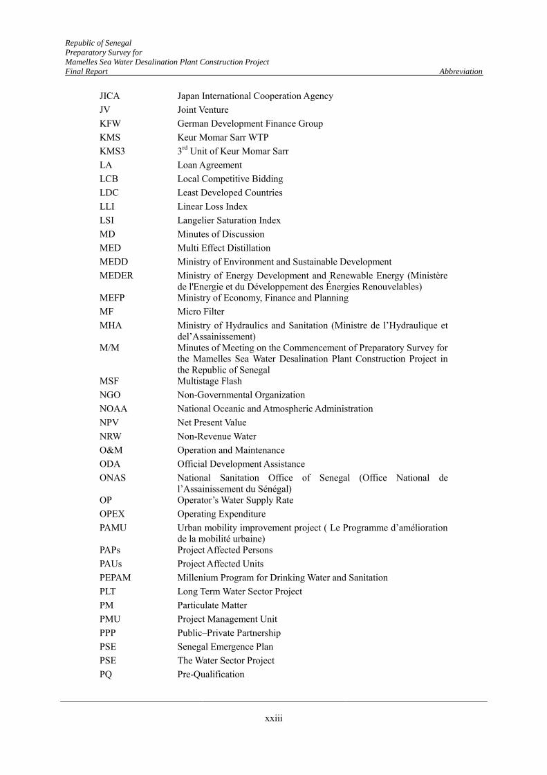
Republic of Senegal
Preparatory Survey for
Mamelles Sea Water Desalination Plant Construction Project
Final Report Abbreviation
xxiii
JICA Japan International Cooperation Agency JV Joint Venture KFW German Development Finance Group KMS Keur Momar Sarr WTP KMS3 3rd Unit of Keur Momar Sarr LA Loan Agreement LCB Local Competitive Bidding LDC Least Developed Countries LLI Linear Loss Index LSI Langelier Saturation Index MD Minutes of Discussion MED Multi Effect Distillation MEDD Ministry of Environment and Sustainable Development MEDER Ministry of Energy Development and Renewable Energy (Ministère
de l'Energie et du Développement des Énergies Renouvelables) MEFP Ministry of Economy, Finance and Planning MF Micro Filter MHA Ministry of Hydraulics and Sanitation (Ministre de l’Hydraulique et
del’Assainissement) M/M Minutes of Meeting on the Commencement of Preparatory Survey for
the Mamelles Sea Water Desalination Plant Construction Project in the Republic of Senegal
MSF Multistage Flash NGO Non-Governmental Organization NOAA National Oceanic and Atmospheric Administration NPV Net Present Value NRW Non-Revenue Water O&M Operation and Maintenance ODA Official Development Assistance ONAS National Sanitation Office of Senegal (Office National de
l’Assainissement du Sénégal) OP Operator’s Water Supply Rate OPEX Operating Expenditure PAMU Urban mobility improvement project ( Le Programme d’amélioration
de la mobilité urbaine) PAPs Project Affected Persons PAUs Project Affected Units PEPAM Millenium Program for Drinking Water and Sanitation PLT Long Term Water Sector Project PM Particulate Matter PMU Project Management Unit PPP Public–Private Partnership PSE Senegal Emergence Plan PSE The Water Sector Project PQ Pre-Qualification
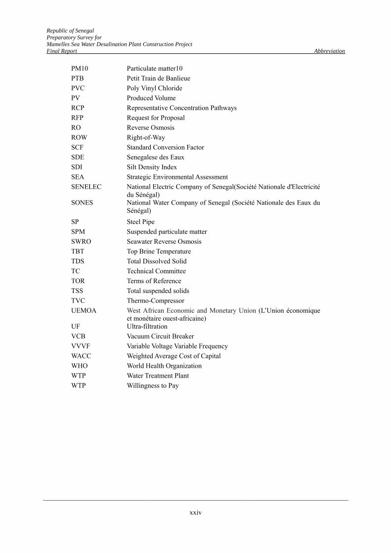
Republic of Senegal
Preparatory Survey for
Mamelles Sea Water Desalination Plant Construction Project
Final Report Abbreviation
xxiv
PM10 Particulate matter10 PTB Petit Train de Banlieue PVC Poly Vinyl Chloride PV Produced Volume RCP Representative Concentration Pathways RFP Request for Proposal RO Reverse Osmosis ROW Right-of-Way SCF Standard Conversion Factor SDE Senegalese des Eaux SDI Silt Density Index SEA Strategic Environmental Assessment SENELEC National Electric Company of Senegal(Société Nationale d'Electricité
du Sénégal) SONES National Water Company of Senegal (Société Nationale des Eaux du
Sénégal) SP Steel Pipe SPM Suspended particulate matter SWRO Seawater Reverse Osmosis TBT Top Brine Temperature TDS Total Dissolved Solid TC Technical Committee TOR Terms of Reference TSS Total suspended solids TVC Thermo-Compressor UEMOA West African Economic and Monetary Union (L’Union économique
et monétaire ouest-africaine) UF Ultra-filtration VCB Vacuum Circuit Breaker VVVF Variable Voltage Variable Frequency WACC Weighted Average Cost of Capital WHO World Health Organization WTP Water Treatment Plant WTP Willingness to Pay
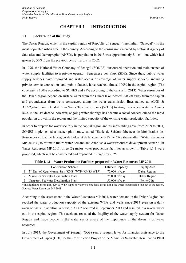
Republic of Senegal Chapter 1
Preparatory Survey for
Mamelles Sea Water Desalination Plant Construction Project
Final Report Introduction
1-1
CHAPTER 1 INTRODUCTION
1.1 Background of the Study
The Dakar Region, which is the capital region of Republic of Senegal (hereinafter, “Senegal”), is the most populated urban area in the country. According to the census implemented by National Agency of Statistics and Demography (ANSD), its population in 2013 was approximately 3.1 million, which had grown by 50% from the previous census results in 2002.
In 1996, the National Water Company of Senegal (SONES) outsourced operation and maintenance of water supply facilities to a private operator, Senegalese des Eaux (SDE). Since then, public water supply services have improved and water access or coverage of water supply services, including private service connections and public faucets, have reached almost 100% in the capital region (The coverage is 100% according to SONES and 97% according to the census in 2013). Water resources of the Dakar Region depend on surface water from the Guiers lake located 250 km away from the capital and groundwater from wells constructed along the water transmission lines named as ALG1 & ALG2,which are extended from Water Treatment Plants (WTPs) treating the surface water of Guiers lake. In the last decade, however, ongoing water shortage has become a social concern due to the rapid population growth in the region and the limited capacity of the existing water production facilities.
In order to prepare for water security in the capital region and its surrounding area, from 2009 to 2011, SONES implemented a master plan study, called “Etude de Schéma Directeur de Mobilisation des
Ressources en Eau de la Region de Dakar et de la Zone de la Petite Côte (hereinafter, "Water Resources MP 2011”)”, to estimate future water demand and establish a water resources development scenario. In Water Resources MP 2011, three (3) major water production facilities as shown in Table 1.1.1 were proposed, which will be constructed and expanded in stages by 2025.
Table 1.1.1 Water Production Facilities proposed in Water Resources MP 2011
Construction Scheme Ultimate Capacity Supply Area 1 3rd Unit of Keur Momar Sarr (KMS) WTP (KMS3 WTP) 75,000 m3/day Dakar Region* 2 Mamelles Seawater Desalination Plant 75,000 m3/day Dakar Region 3 Ngaparou Seawater Desalination Plant 50,000 m3/day Petite Côte
* In addition to the region, KMS3 WTP supplies water to some local areas along the water transmission line out of the region. Source: Water Resources MP 2011
According to the assessment in the Water Resources MP 2011, water demand in the Dakar Region has reached the water production capacity of the existing WTPs and wells since 2013 even on a daily average basis. In addition, a burst in ALG2 occurred in September 2013 and resulted in a severe water cut in the capital region. This accident revealed the fragility of the water supply system for Dakar Region and made people in the water sector aware of the importance of the diversity of water resources.
In July 2013, the Government of Senegal (GOS) sent a request letter for financial assistance to the Government of Japan (GOJ) for the Construction Project of the Mamelles Seawater Desalination Plant.
Republic of Senegal Chapter 1
Preparatory Survey for
Mamelles Sea Water Desalination Plant Construction Project
Final Report Introduction
1-2
From December 2013 to March 2014, corresponding to the request from GOS, Japan International Cooperation Agency (JICA) carried out a study, named the Information Collection Survey on Water Supply for Dakar Region (hereinafter, “Information Collection Study 2014”)to collect information related to the desalination plant project and to preliminarily verify the validity of the project. After reviewing the study results, GOJ and JICA decided to carry out the Preparatory Survey on the Mamelles Sea Water Desalination Plant Construction Project (hereinafter, “the Study”).
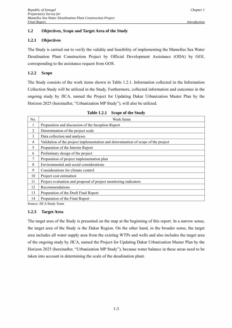
Republic of Senegal Chapter 1
Preparatory Survey for
Mamelles Sea Water Desalination Plant Construction Project
Final Report Introduction
1-3
1.2 Objectives, Scope and Target Area of the Study
1.2.1 Objectives
The Study is carried out to verify the validity and feasibility of implementing the Mamelles Sea Water Desalination Plant Construction Project by Official Development Assistance (ODA) by GOJ, corresponding to the assistance request from GOS.
1.2.2 Scope
The Study consists of the work items shown in Table 1.2.1. Information collected in the Information Collection Study will be utilized in the Study. Furthermore, collected information and outcomes in the ongoing study by JICA, named the Project for Updating Dakar Urbanization Master Plan by the Horizon 2025 (hereinafter, “Urbanization MP Study”), will also be utilized.
Table 1.2.1 Scope of the Study
No. Work Items 1 Preparation and discussion of the Inception Report 2 Determination of the project scale 3 Data collection and analyses 4 Validation of the project implementation and determination of scope of the project 5 Preparation of the Interim Report 6 Preliminary design of the project 7 Preparation of project implementation plan 8 Environmental and social considerations 9 Considerations for climate control
10 Project cost estimation 11 Project evaluation and proposal of project monitoring indicators 12 Recommendations 13 Preparation of the Draft Final Report 14 Preparation of the Final Report
Source: JICA Study Team
1.2.3 Target Area
The target area of the Study is presented on the map at the beginning of this report. In a narrow sense, the target area of the Study is the Dakar Region. On the other hand, in the broader sense, the target area includes all water supply area from the existing WTPs and wells and also includes the target area of the ongoing study by JICA, named the Project for Updating Dakar Urbanization Master Plan by the Horizon 2025 (hereinafter, “Urbanization MP Study”), because water balance in these areas need to be taken into account in determining the scale of the desalination plant.
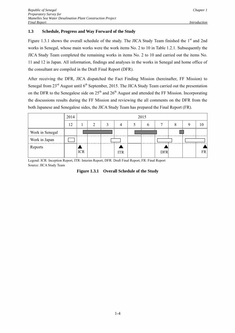
Republic of Senegal Chapter 1
Preparatory Survey for
Mamelles Sea Water Desalination Plant Construction Project
Final Report Introduction
1-4
1.3 Schedule, Progress and Way Forward of the Study
Figure 1.3.1 shows the overall schedule of the study. The JICA Study Team finished the 1st and 2nd works in Senegal, whose main works were the work items No. 2 to 10 in Table 1.2.1. Subsequently the JICA Study Team completed the remaining works in items No. 2 to 10 and carried out the items No. 11 and 12 in Japan. All information, findings and analyses in the works in Senegal and home office of the consultant are compiled in the Draft Final Report (DFR).
After receiving the DFR, JICA dispatched the Fact Finding Mission (hereinafter, FF Mission) to Senegal from 23rd August until 6th September, 2015. The JICA Study Team carried out the presentation on the DFR to the Senegalese side on 25th and 26th August and attended the FF Mission. Incorporating the discussions results during the FF Mission and reviewing the all comments on the DFR from the both Japanese and Senegalese sides, the JICA Study Team has prepared the Final Report (FR).
2014 2015
12 1 2 3 4 5 6 7 8 9 10
Work in Senegal
Work in Japan
Reports
Legend: ICR: Inception Report, ITR: Interim Report, DFR: Draft Final Report, FR: Final Report Source: JICA Study Team
Figure 1.3.1 Overall Schedule of the Study
ICR ITR DFR FR
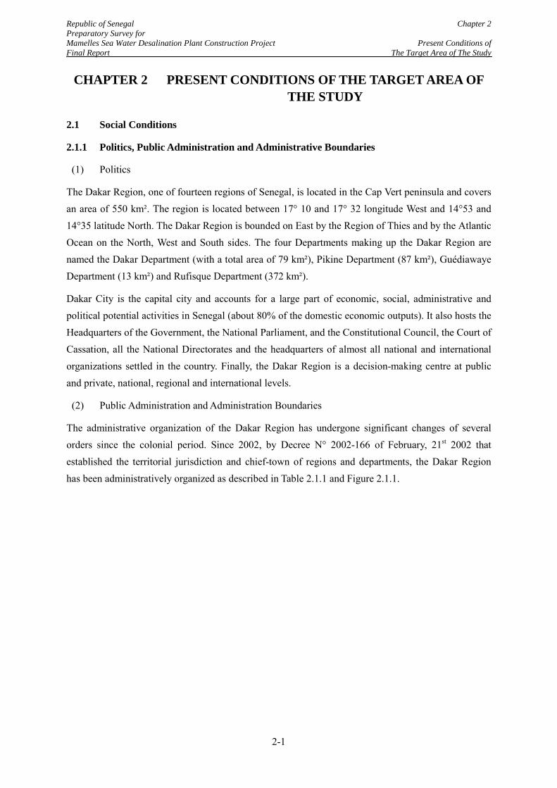
Republic of Senegal Chapter 2 Preparatory Survey for Mamelles Sea Water Desalination Plant Construction Project Present Conditions of Final Report The Target Area of The Study
CHAPTER 2 PRESENT CONDITIONS OF THE TARGET AREA OF THE STUDY
2.1 Social Conditions
2.1.1 Politics, Public Administration and Administrative Boundaries
(1) Politics
The Dakar Region, one of fourteen regions of Senegal, is located in the Cap Vert peninsula and covers an area of 550 km². The region is located between 17° 10 and 17° 32 longitude West and 14°53 and 14°35 latitude North. The Dakar Region is bounded on East by the Region of Thies and by the Atlantic Ocean on the North, West and South sides. The four Departments making up the Dakar Region are named the Dakar Department (with a total area of 79 km²), Pikine Department (87 km²), Guédiawaye Department (13 km²) and Rufisque Department (372 km²).
Dakar City is the capital city and accounts for a large part of economic, social, administrative and political potential activities in Senegal (about 80% of the domestic economic outputs). It also hosts the Headquarters of the Government, the National Parliament, and the Constitutional Council, the Court of Cassation, all the National Directorates and the headquarters of almost all national and international organizations settled in the country. Finally, the Dakar Region is a decision-making centre at public and private, national, regional and international levels.
(2) Public Administration and Administration Boundaries
The administrative organization of the Dakar Region has undergone significant changes of several orders since the colonial period. Since 2002, by Decree N° 2002-166 of February, 21st 2002 that established the territorial jurisdiction and chief-town of regions and departments, the Dakar Region has been administratively organized as described in Table 2.1.1 and Figure 2.1.1.
2-1
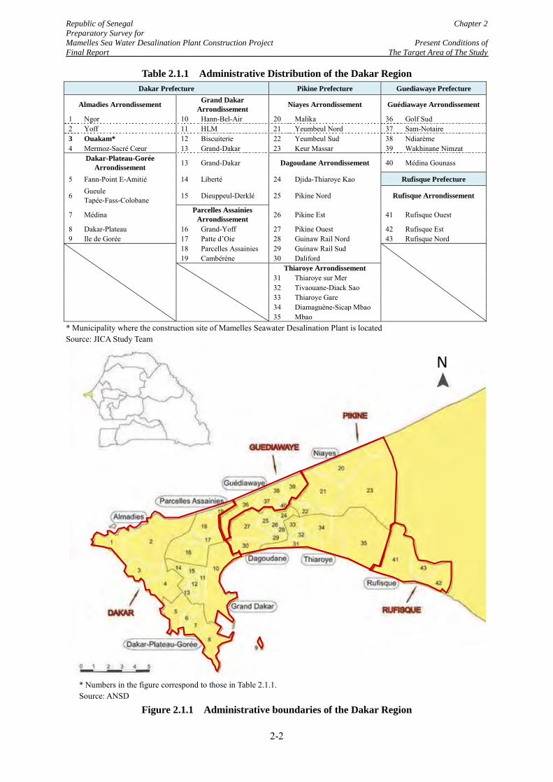
Republic of Senegal Chapter 2 Preparatory Survey for Mamelles Sea Water Desalination Plant Construction Project Present Conditions of Final Report The Target Area of The Study
Table 2.1.1 Administrative Distribution of the Dakar Region Dakar Prefecture Pikine Prefecture Guediawaye Prefecture
Almadies Arrondissement Grand Dakar Arrondissement Niayes Arrondissement Guédiawaye Arrondissement
1 Ngor 10 Hann-Bel-Air 20 Malika 36 Golf Sud 2 Yoff 11 HLM 21 Yeumbeul Nord 37 Sam-Notaire 3 Ouakam* 12 Biscuiterie 22 Yeumbeul Sud 38 Ndiarème 4 Mermoz-Sacré Cœur 13 Grand-Dakar 23 Keur Massar 39 Wakhinane Nimzat
Dakar-Plateau-Gorée Arrondissement 13 Grand-Dakar Dagoudane Arrondissement 40 Médina Gounass
5 Fann-Point E-Amitié 14 Liberté 24 Djida-Thiaroye Kao Rufisque Prefecture
6 Gueule Tapée-Fass-Colobane 15 Dieuppeul-Derklé 25 Pikine Nord Rufisque Arrondissement
7 Médina Parcelles Assainies Arrondissement 26 Pikine Est 41 Rufisque Ouest
8 Dakar-Plateau 16 Grand-Yoff 27 Pikine Ouest 42 Rufisque Est 9 Ile de Gorée 17 Patte d’Oie 28 Guinaw Rail Nord 43 Rufisque Nord
18 Parcelles Assainies 29 Guinaw Rail Sud
19 Cambérène 30 Daliford
Thiaroye Arrondissement 31 Thiaroye sur Mer 32 Tivaouane-Diack Sao 33 Thiaroye Gare 34 Diamaguène-Sicap Mbao 35 Mbao
* Municipality where the construction site of Mamelles Seawater Desalination Plant is located Source: JICA Study Team
* Numbers in the figure correspond to those in Table 2.1.1. Source: ANSD
Figure 2.1.1 Administrative boundaries of the Dakar Region
N
2-2
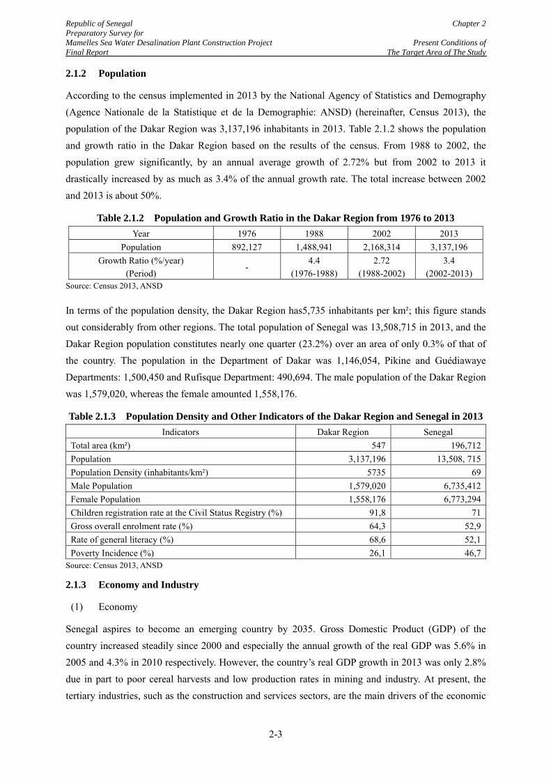
Republic of Senegal Chapter 2 Preparatory Survey for Mamelles Sea Water Desalination Plant Construction Project Present Conditions of Final Report The Target Area of The Study
2.1.2 Population
According to the census implemented in 2013 by the National Agency of Statistics and Demography (Agence Nationale de la Statistique et de la Demographie: ANSD) (hereinafter, Census 2013), the population of the Dakar Region was 3,137,196 inhabitants in 2013. Table 2.1.2 shows the population and growth ratio in the Dakar Region based on the results of the census. From 1988 to 2002, the population grew significantly, by an annual average growth of 2.72% but from 2002 to 2013 it drastically increased by as much as 3.4% of the annual growth rate. The total increase between 2002 and 2013 is about 50%.
Table 2.1.2 Population and Growth Ratio in the Dakar Region from 1976 to 2013 Year 1976 1988 2002 2013
Population 892,127 1,488,941 2,168,314 3,137,196 Growth Ratio (%/year)
(Period) -
4.4 (1976-1988)
2.72 (1988-2002)
3.4 (2002-2013)
Source: Census 2013, ANSD
In terms of the population density, the Dakar Region has5,735 inhabitants per km²; this figure stands out considerably from other regions. The total population of Senegal was 13,508,715 in 2013, and the Dakar Region population constitutes nearly one quarter (23.2%) over an area of only 0.3% of that of the country. The population in the Department of Dakar was 1,146,054, Pikine and Guédiawaye Departments: 1,500,450 and Rufisque Department: 490,694. The male population of the Dakar Region was 1,579,020, whereas the female amounted 1,558,176.
Table 2.1.3 Population Density and Other Indicators of the Dakar Region and Senegal in 2013 Indicators Dakar Region Senegal
Total area (km²) 547 196,712 Population 3,137,196 13,508, 715 Population Density (inhabitants/km²) 5735 69 Male Population 1,579,020 6,735,412 Female Population 1,558,176 6,773,294 Children registration rate at the Civil Status Registry (%) 91,8 71 Gross overall enrolment rate (%) 64,3 52,9 Rate of general literacy (%) 68,6 52,1 Poverty Incidence (%) 26,1 46,7
Source: Census 2013, ANSD
2.1.3 Economy and Industry
(1) Economy
Senegal aspires to become an emerging country by 2035. Gross Domestic Product (GDP) of the country increased steadily since 2000 and especially the annual growth of the real GDP was 5.6% in 2005 and 4.3% in 2010 respectively. However, the country’s real GDP growth in 2013 was only 2.8% due in part to poor cereal harvests and low production rates in mining and industry. At present, the tertiary industries, such as the construction and services sectors, are the main drivers of the economic
2-3
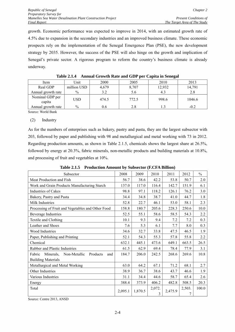
Republic of Senegal Chapter 2 Preparatory Survey for Mamelles Sea Water Desalination Plant Construction Project Present Conditions of Final Report The Target Area of The Study
growth. Economic performance was expected to improve in 2014, with an estimated growth rate of 4.5% due to expansion in the secondary industries and an improved business climate. These economic prospects rely on the implementation of the Senegal Emergence Plan (PSE), the new development strategy by 2035. However, the success of the PSE will also hinge on the growth and implication of Senegal’s private sector. A rigorous program to reform the country’s business climate is already underway.
Table 2.1.4 Annual Growth Rate and GDP per Capita in Senegal Item Unit 2000 2005 2010 2013
Real GDP million USD 4,679 8,707 12,932 14,791 Annual growth rate % 3.2 5.6 4.3 2.8 Nominal GDP per
capita USD 474.5 772.5 998.6 1046.6
Annual growth rate % 0.6 2.8 1.3 -0.2 Source: World Bank
(2) Industry
As for the numbers of enterprises such as bakery, pastry and pasta, they are the largest subsector with 203, followed by paper and publishing with 98 and metallurgical and metal working with 73 in 2012. Regarding production amounts, as shown in Table 2.1.5, chemicals shows the largest share at 26.5%, followed by energy at 20.3%, fabric minerals, non-metallic products and building materials at 10.8%, and processing of fruit and vegetables at 10%.
Table 2.1.5 Production Amount by Subsector (F.CFA Billion) Subsector 2008 2009 2010 2011 2012 %
Meat Production and Fish 56.7 38.6 42.2 53.8 50.7 2.0 Work and Grain Products Manufacturing Starch 137.0 117.0 116.4 142.7 151.9 6.1 Industries of Cakes 98.8 97.1 118.2 126.1 76.2 3.0 Bakery, Pastry and Pasta 34.4 34.8 38.7 41.0 44.7 1.8 Milk Industries 52.8 22.7 46.1 53.0 58.1 2.3 Processing of Fruit and Vegetables and Other Food 158.8 180.7 205.6 228.3 250.6 10.0 Beverage Industries 52.5 55.1 58.6 58.5 54.3 2.2 Textile and Clothing 10.1 9.3 9.4 7.2 7.2 0.3 Leather and Shoes 7.6 5.3 6.1 7.7 8.0 0.3 Wood Industries 34.6 32.7 33.8 47.5 46.5 1.9 Paper, Publishing and Printing 52.1 54.3 55.3 57.8 55.8 2.2 Chemical 632.1 445.1 473.6 649.1 663.5 26.5 Rubber and Plastic Industries 61.5 62.9 69.4 78.4 77.9 3.1 Fabric Minerals, Non-Metallic Products and Building Materials
184.7 206.0 242.5 268.6 269.6 10.8
Metallurgical and Metal Working 63.0 64.2 67.1 71.2 68.1 2.7 Other Industries 38.9 36.7 38.6 43.7 46.6 1.9 Various Industries 31.1 34.4 44.6 58.7 65.4 2.6 Energy 388.4 373.9 406.2 482.8 508.5 20.3 Total
2,095.1 1,870.5 2,072.
3 2,475.9
2,503.7
100.0
Source: Centre 2013, ANSD
2-4
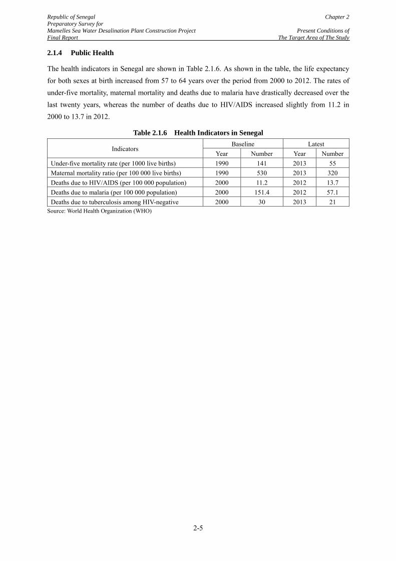
Republic of Senegal Chapter 2 Preparatory Survey for Mamelles Sea Water Desalination Plant Construction Project Present Conditions of Final Report The Target Area of The Study
2.1.4 Public Health
The health indicators in Senegal are shown in Table 2.1.6. As shown in the table, the life expectancy for both sexes at birth increased from 57 to 64 years over the period from 2000 to 2012. The rates of under-five mortality, maternal mortality and deaths due to malaria have drastically decreased over the last twenty years, whereas the number of deaths due to HIV/AIDS increased slightly from 11.2 in 2000 to 13.7 in 2012.
Table 2.1.6 Health Indicators in Senegal
Indicators Baseline Latest
Year Number Year Number Under-five mortality rate (per 1000 live births) 1990 141 2013 55 Maternal mortality ratio (per 100 000 live births) 1990 530 2013 320 Deaths due to HIV/AIDS (per 100 000 population) 2000 11.2 2012 13.7 Deaths due to malaria (per 100 000 population) 2000 151.4 2012 57.1 Deaths due to tuberculosis among HIV-negative 2000 30 2013 21
Source: World Health Organization (WHO)
2-5
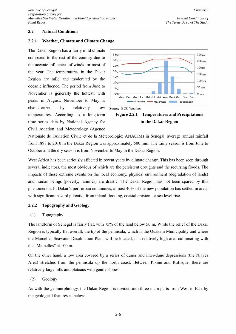
Republic of Senegal Chapter 2 Preparatory Survey for Mamelles Sea Water Desalination Plant Construction Project Present Conditions of Final Report The Target Area of The Study
2.2 Natural Conditions
2.2.1 Weather, Climate and Climate Change
The Dakar Region has a fairly mild climate compared to the rest of the country due to the oceanic influences of winds for most of the year. The temperatures in the Dakar Region are mild and moderated by the oceanic influence. The period from June to November is generally the hottest, with peaks in August. November to May is characterized by relatively low temperatures. According to a long-term time series data by National Agency for Civil Aviation and Meteorology (Agence Nationale de l'Aviation Civile et de la Météorologie: ANACIM) in Senegal, average annual rainfall from 1898 to 2010 in the Dakar Region was approximately 500 mm. The rainy season is from June to October and the dry season is from November to May in the Dakar Region.
West Africa has been seriously affected in recent years by climate change. This has been seen through several indicators, the most obvious of which are the persistent droughts and the recurring floods. The impacts of these extreme events on the local economy, physical environment (degradation of lands) and human beings (poverty, famines) are drastic. The Dakar Region has not been spared by this phenomenon. In Dakar’s peri-urban communes, almost 40% of the new population has settled in areas with significant hazard potential from inland flooding, coastal erosion, or sea level rise.
2.2.2 Topography and Geology
(1) Topography
The landform of Senegal is fairly flat, with 75% of the land below 50 m. While the relief of the Dakar Region is typically flat overall, the tip of the peninsula, which is the Ouakam Municipality and where the Mamelles Seawater Desalination Plant will be located, is a relatively high area culminating with the “Mamelles” at 100 m.
On the other hand, a low area covered by a series of dunes and inter-dune depressions (the Niayes Area) stretches from the peninsula up the north coast. Between Pikine and Rufisque, there are relatively large hills and plateaus with gentle slopes.
(2) Geology
As with the geomorphology, the Dakar Region is divided into three main parts from West to East by the geological features as below:
Source: BCC Weather
Figure 2.2.1 Temperatures and Precipitations in the Dakar Region
Mi nimum Maximum P articipation
J an . F év. Mar . A vr. Mai J uin J ul. A oût Sept. Oct. Nov. Déc .
2-6
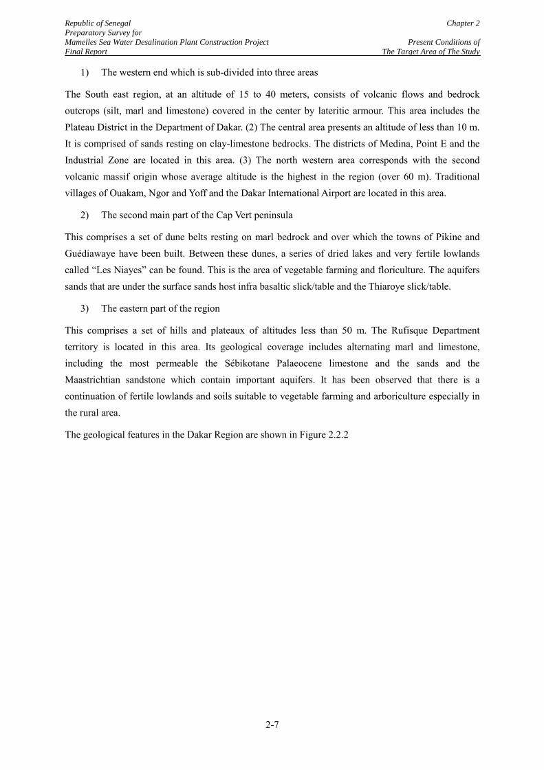
Republic of Senegal Chapter 2 Preparatory Survey for Mamelles Sea Water Desalination Plant Construction Project Present Conditions of Final Report The Target Area of The Study
1) The western end which is sub-divided into three areas
The South east region, at an altitude of 15 to 40 meters, consists of volcanic flows and bedrock outcrops (silt, marl and limestone) covered in the center by lateritic armour. This area includes the Plateau District in the Department of Dakar. (2) The central area presents an altitude of less than 10 m. It is comprised of sands resting on clay-limestone bedrocks. The districts of Medina, Point E and the Industrial Zone are located in this area. (3) The north western area corresponds with the second volcanic massif origin whose average altitude is the highest in the region (over 60 m). Traditional villages of Ouakam, Ngor and Yoff and the Dakar International Airport are located in this area.
2) The second main part of the Cap Vert peninsula
This comprises a set of dune belts resting on marl bedrock and over which the towns of Pikine and Guédiawaye have been built. Between these dunes, a series of dried lakes and very fertile lowlands called “Les Niayes” can be found. This is the area of vegetable farming and floriculture. The aquifers sands that are under the surface sands host infra basaltic slick/table and the Thiaroye slick/table.
3) The eastern part of the region
This comprises a set of hills and plateaux of altitudes less than 50 m. The Rufisque Department territory is located in this area. Its geological coverage includes alternating marl and limestone, including the most permeable the Sébikotane Palaeocene limestone and the sands and the Maastrichtian sandstone which contain important aquifers. It has been observed that there is a continuation of fertile lowlands and soils suitable to vegetable farming and arboriculture especially in the rural area.
The geological features in the Dakar Region are shown in Figure 2.2.2
2-7
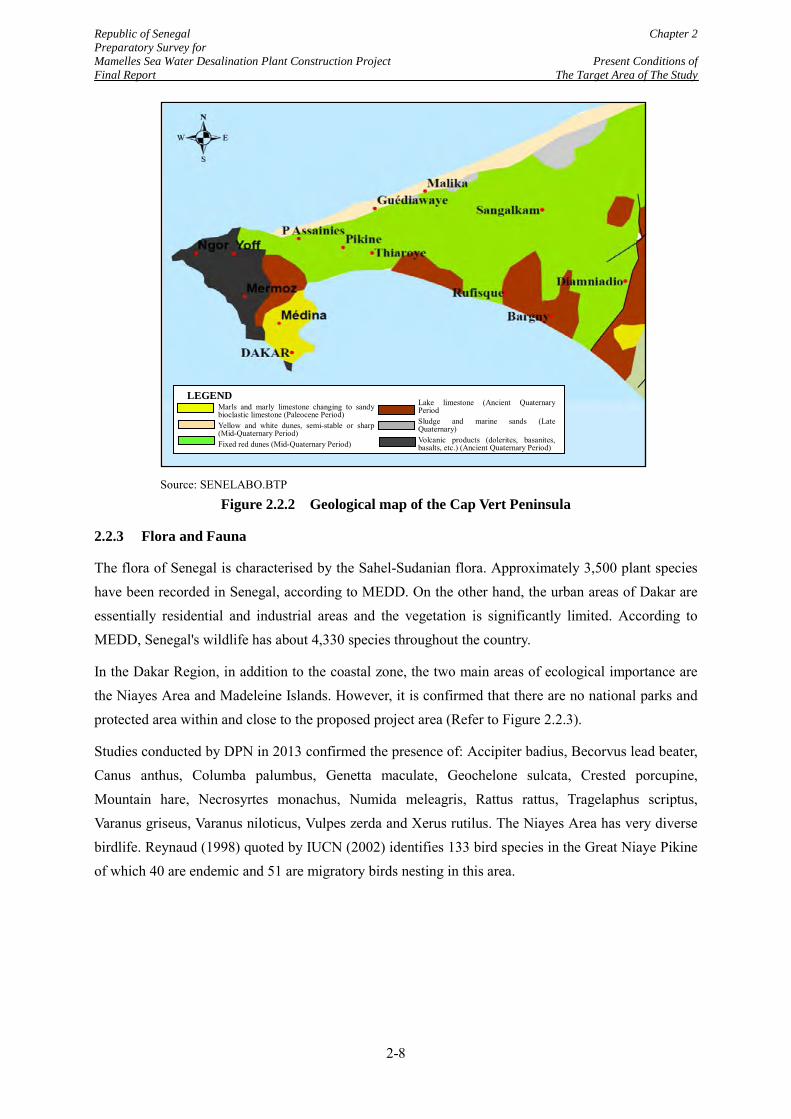
Republic of Senegal Chapter 2 Preparatory Survey for Mamelles Sea Water Desalination Plant Construction Project Present Conditions of Final Report The Target Area of The Study
Source: SENELABO.BTP
Figure 2.2.2 Geological map of the Cap Vert Peninsula
2.2.3 Flora and Fauna
The flora of Senegal is characterised by the Sahel-Sudanian flora. Approximately 3,500 plant species have been recorded in Senegal, according to MEDD. On the other hand, the urban areas of Dakar are essentially residential and industrial areas and the vegetation is significantly limited. According to MEDD, Senegal's wildlife has about 4,330 species throughout the country.
In the Dakar Region, in addition to the coastal zone, the two main areas of ecological importance are the Niayes Area and Madeleine Islands. However, it is confirmed that there are no national parks and protected area within and close to the proposed project area (Refer to Figure 2.2.3).
Studies conducted by DPN in 2013 confirmed the presence of: Accipiter badius, Becorvus lead beater, Canus anthus, Columba palumbus, Genetta maculate, Geochelone sulcata, Crested porcupine, Mountain hare, Necrosyrtes monachus, Numida meleagris, Rattus rattus, Tragelaphus scriptus, Varanus griseus, Varanus niloticus, Vulpes zerda and Xerus rutilus. The Niayes Area has very diverse birdlife. Reynaud (1998) quoted by IUCN (2002) identifies 133 bird species in the Great Niaye Pikine of which 40 are endemic and 51 are migratory birds nesting in this area.
Marls and marly limestone changing to sandy bioclastic limestone (Paleocene Period) Yellow and white dunes, semi-stable or sharp (Mid-Quaternary Period) Fixed red dunes (Mid-Quaternary Period)
Lake limestone (Ancient Quaternary Period Sludge and marine sands (Late Quaternary) Volcanic products (dolerites, basanites, basalts, etc.) (Ancient Quaternary Period)
LEGEND
2-8
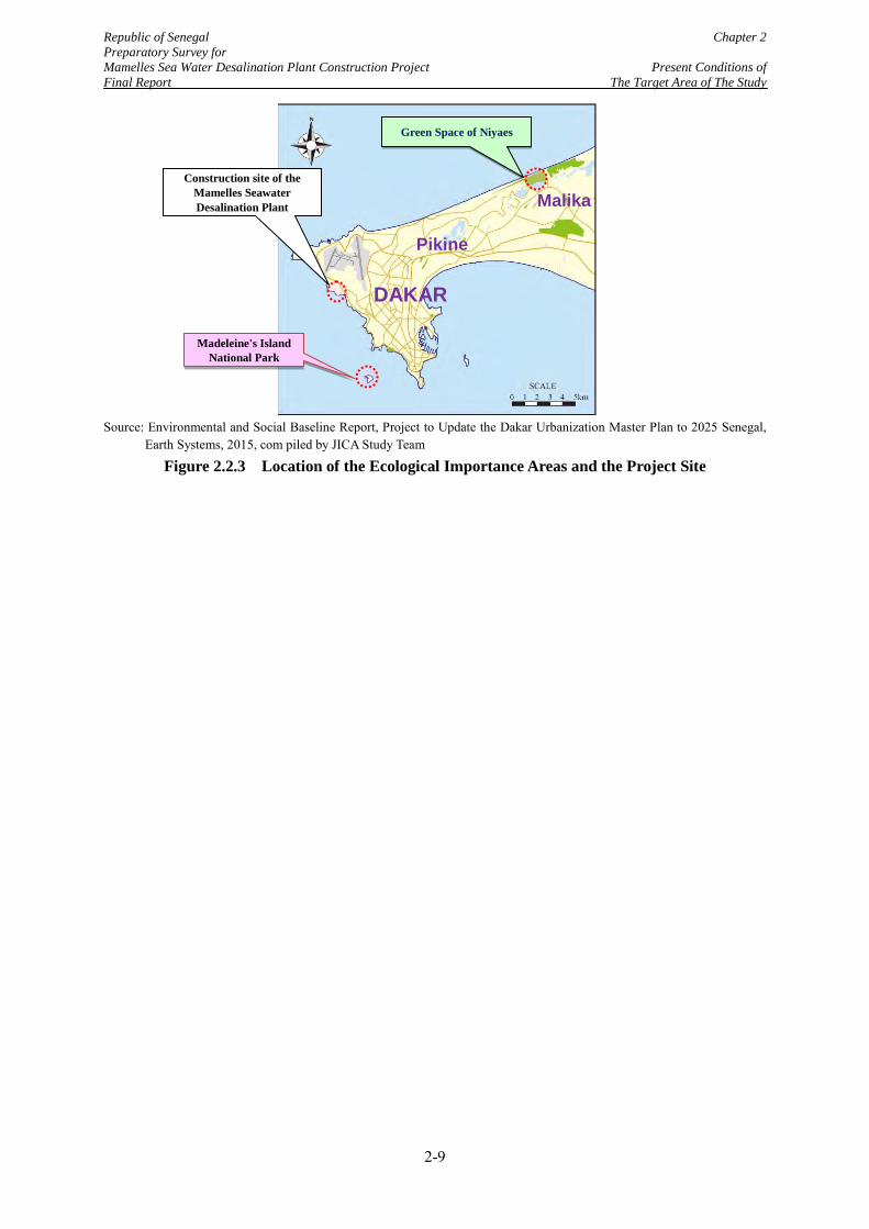
Republic of Senegal Chapter 2 Preparatory Survey for Mamelles Sea Water Desalination Plant Construction Project Present Conditions of Final Report The Target Area of The Study
Source: Environmental and Social Baseline Report, Project to Update the Dakar Urbanization Master Plan to 2025 Senegal,
Earth Systems, 2015, com piled by JICA Study Team
Figure 2.2.3 Location of the Ecological Importance Areas and the Project Site
Green Space of Niyaes
Madeleine's Island National Park
DAKAR
Pikine
Malika Construction site of the
Mamelles Seawater Desalination Plant
2-9
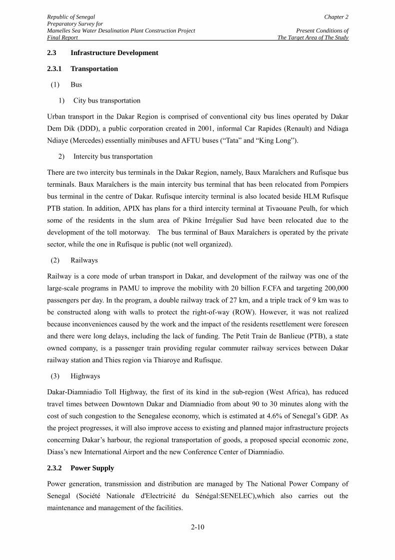
Republic of Senegal Chapter 2 Preparatory Survey for Mamelles Sea Water Desalination Plant Construction Project Present Conditions of Final Report The Target Area of The Study
2.3 Infrastructure Development
2.3.1 Transportation
(1) Bus
1) City bus transportation
Urban transport in the Dakar Region is comprised of conventional city bus lines operated by Dakar Dem Dik (DDD), a public corporation created in 2001, informal Car Rapides (Renault) and Ndiaga Ndiaye (Mercedes) essentially minibuses and AFTU buses (“Tata” and “King Long”).
2) Intercity bus transportation
There are two intercity bus terminals in the Dakar Region, namely, Baux Maraîchers and Rufisque bus terminals. Baux Maraîchers is the main intercity bus terminal that has been relocated from Pompiers bus terminal in the centre of Dakar. Rufisque intercity terminal is also located beside HLM Rufisque PTB station. In addition, APIX has plans for a third intercity terminal at Tivaouane Peulh, for which some of the residents in the slum area of Pikine Irrégulier Sud have been relocated due to the development of the toll motorway. The bus terminal of Baux Maraîchers is operated by the private sector, while the one in Rufisque is public (not well organized).
(2) Railways
Railway is a core mode of urban transport in Dakar, and development of the railway was one of the large-scale programs in PAMU to improve the mobility with 20 billion F.CFA and targeting 200,000 passengers per day. In the program, a double railway track of 27 km, and a triple track of 9 km was to be constructed along with walls to protect the right-of-way (ROW). However, it was not realized because inconveniences caused by the work and the impact of the residents resettlement were foreseen and there were long delays, including the lack of funding. The Petit Train de Banlieue (PTB), a state owned company, is a passenger train providing regular commuter railway services between Dakar railway station and Thies region via Thiaroye and Rufisque.
(3) Highways
Dakar-Diamniadio Toll Highway, the first of its kind in the sub-region (West Africa), has reduced travel times between Downtown Dakar and Diamniadio from about 90 to 30 minutes along with the cost of such congestion to the Senegalese economy, which is estimated at 4.6% of Senegal’s GDP. As the project progresses, it will also improve access to existing and planned major infrastructure projects concerning Dakar’s harbour, the regional transportation of goods, a proposed special economic zone, Diass’s new International Airport and the new Conference Center of Diamniadio.
2.3.2 Power Supply
Power generation, transmission and distribution are managed by The National Power Company of Senegal (Société Nationale d'Electricité du Sénégal:SENELEC),which also carries out the maintenance and management of the facilities.
2-10
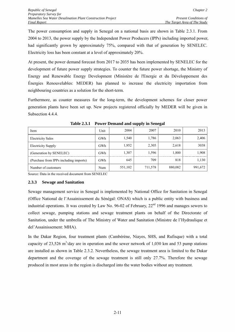
Republic of Senegal Chapter 2 Preparatory Survey for Mamelles Sea Water Desalination Plant Construction Project Present Conditions of Final Report The Target Area of The Study
The power consumption and supply in Senegal on a national basis are shown in Table 2.3.1. From 2004 to 2013, the power supply by the Independent Power Producers (IPPs) including imported power, had significantly grown by approximately 75%, compared with that of generation by SENELEC. Electricity loss has been constant at a level of approximately 20%.
At present, the power demand forecast from 2017 to 2035 has been implemented by SENELEC for the development of future power supply strategies. To counter the future power shortage, the Ministry of Energy and Renewable Energy Development (Ministère de l'Energie et du Développement des Énergies Renouvelables: MEDER) has planned to increase the electricity importation from neighbouring countries as a solution for the short-term.
Furthermore, as counter measures for the long-term, the development schemes for closer power generation plants have been set up. New projects registered officially by MEDER will be given in Subsection 4.4.4.
Table 2.3.1 Power Demand and supply in Senegal Item Unit 2004 2007 2010 2013
Electricity Sales GWh 1,540 1,786 2,063 2,406
Electricity Supply GWh 1,952 2,305 2,618 3038
(Generation by SENELEC) GWh 1,307 1,596 1,800 1,908
(Purchase from IPPs including imports) GWh 645 709 818 1,130
Number of customers Num 551,102 711,578 880,082 991,672
Source: Data in the received document from SENELEC
2.3.3 Sewage and Sanitation
Sewage management service in Senegal is implemented by National Office for Sanitation in Senegal (Office National de l’Assainissement du Sénégal: ONAS) which is a public entity with business and industrial operations. It was created by Law No. 96-02 of February, 22nd 1996 and manages sewers to collect sewage, pumping stations and sewage treatment plants on behalf of the Directorate of Sanitation, under the umbrella of The Ministry of Water and Sanitation (Ministre de l’Hydraulique et del’Assainissement: MHA).
In the Dakar Region, four treatment plants (Cambérène, Niayes, SHS, and Rufisque) with a total capacity of 23,526 m3/day are in operation and the sewer network of 1,030 km and 53 pump stations are installed as shown in Table 2.3.2. Nevertheless, the sewage treatment area is limited to the Dakar department and the coverage of the sewage treatment is still only 27.7%. Therefore the sewage produced in most areas in the region is discharged into the water bodies without any treatment.
2-11
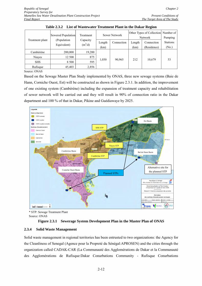
Republic of Senegal Chapter 2 Preparatory Survey for Mamelles Sea Water Desalination Plant Construction Project Present Conditions of Final Report The Target Area of The Study
Table 2.3.2 List of Wastewater Treatment Plant in the Dakar Region
Treatment plant Sewered Population
(Population Equivalent)
Treatment Capacity
(m3/d)
Sewer Network Other Types of Collection
Network Number of Pumping Stations
(No.) Length (km)
Connection Length (km)
Connection (Residence)
Cambérène 200,000 19,200
1,030 90,965 212 10,679 53 Niayes 12 500 875 SHS 8 500 595
Rufisque 45,403 2,856 Source: ONAS
Based on the Sewage Master Plan Study implemented by ONAS, three new sewage systems (Baie de Hann, Corniche Ouest, Est) will be constructed as shown in Figure 2.3.1. In addition, the improvement of one existing system (Cambérène) including the expansion of treatment capacity and rehabilitation of sewer network will be carried out and they will result in 90% of connection ratio in the Dakar department and 100 % of that in Dakar, Pikine and Guédiawaye by 2025.
* STP: Sewage Treatment Plant Source: ONAS
Figure 2.3.1 Sewerage System Development Plan in the Master Plan of ONAS
2.3.4 Solid Waste Management
Solid waste management in regional territories has been entrusted to two organizations: the Agency for the Cleanliness of Senegal (Agence pour la Propreté du Sénégal:APROSEN) and the cities through the organization called CADAK-CAR (La Communauté des Agglomérations de Dakar et la Communauté des Agglomérations de Rufisque:Dakar Conurbations Community - Rufisque Conurbations
Cambérène STP
Planned STPs
Alternative site for the planned STP
Est Basin
Cambérène Basin
Comiche Ouest Basin
Bal de Hann Basin
SHS STP
Niayes STP
2-12
Republic of Senegal Chapter 2 Preparatory Survey for Mamelles Sea Water Desalination Plant Construction Project Present Conditions of Final Report The Target Area of The Study
Community). These Government organizations have signed contracts with private operators for collecting household waste, namely the enterprise Veolia Cleanliness (since October, 5th 2005).
For the disposal of waste from the Dakar Region, the Mbeubeus Landfill Site and Mbao sorting & transfer station are in use.
The Mbeubeus Landfill Site is located in the Atlantic littoral zone15 km north-east of downtown Dakar. The operation of the landfill was started in 1968, and it receives about 1,800 to 2,100 tons/day of waste from the Dakar Region. Nevertheless, due to safety issues, it was decided to stop the usage of the Mbeubeuss Landfill Site by the Project carried out by Agence de Développement Municipal (ADM) and the World Bank
Therefore the Sindia Landfill Site with 61 ha of total area, located at the border between two communes of Sindia and Ndiass in Mbour Department approximately 50km from Dakar City, was developed as a new land fill site. Nevertheless, use of it was not started due to strong opposition by the residents living near the site, and the waste is being delivered to the Mbeubeus Landfill Site.
2-13
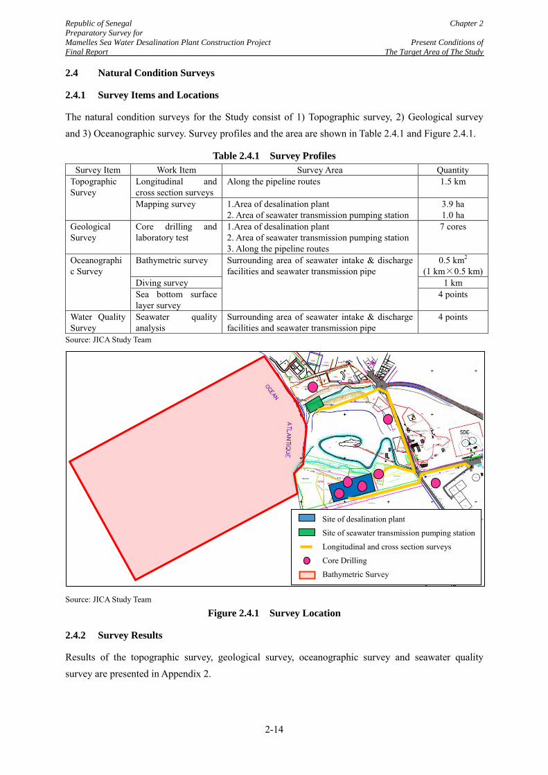
Republic of Senegal Chapter 2 Preparatory Survey for Mamelles Sea Water Desalination Plant Construction Project Present Conditions of Final Report The Target Area of The Study
2.4 Natural Condition Surveys
2.4.1 Survey Items and Locations
The natural condition surveys for the Study consist of 1) Topographic survey, 2) Geological survey and 3) Oceanographic survey. Survey profiles and the area are shown in Table 2.4.1 and Figure 2.4.1.
Table 2.4.1 Survey Profiles Survey Item Work Item Survey Area Quantity
Topographic Survey
Longitudinal and cross section surveys
Along the pipeline routes 1.5 km
Mapping survey 1.Area of desalination plant 2. Area of seawater transmission pumping station
3.9 ha 1.0 ha
Geological Survey
Core drilling and laboratory test
1.Area of desalination plant 2. Area of seawater transmission pumping station 3. Along the pipeline routes
7 cores
Oceanographic Survey
Bathymetric survey Surrounding area of seawater intake & discharge facilities and seawater transmission pipe
0.5 km2 (1 km×0.5 km)
Diving survey 1 km Sea bottom surface layer survey
4 points
Water Quality Survey
Seawater quality analysis
Surrounding area of seawater intake & discharge facilities and seawater transmission pipe
4 points
Source: JICA Study Team
Source: JICA Study Team
Figure 2.4.1 Survey Location
2.4.2 Survey Results
Results of the topographic survey, geological survey, oceanographic survey and seawater quality survey are presented in Appendix 2.
Site of desalination plant
Site of seawater transmission pumping station
Longitudinal and cross section surveys
Core Drilling
Bathymetric Survey
2-14
Republic of Senegal Chapter 3 Preparatory Survey for Mamelles Sea Water Desalination Plant Construction Project Present Situation of Final Report The Water Sector in the Target Area
CHAPTER 3 PRESENT SITUATION OF THE WATER SECTOR IN THE TARGET AREA
3.1 National Policies and Legal Systems in the Water Sector
3.1.1 National Policies
In the water sector in Senegal, the government, represented by the Ministry of Hydraulic and Sanitation (MHA), is always the delegating authority which makes the policies and approves all the plans and projects. Decision makings of MHA in the urban water supply sector are executed based on the following national policies:
Ensure an integrated and efficient management of all water services in order to satisfy all the demand in the water sector
Ensure universal access to drinking water through the reinforcement of existing facilities in order to guarantee the continuity of public water supply
Ensure good management of the water sector
The goal is to ensure that everybody has access to drinking water with no regard to financial and social status, and all the activities of water supply services can be accomplished without any type of discrimination by corporations (public or private).
3.1.2 Fundamental Law and Contracts in the Water Sector
The most fundamental law in the water sector in Senegal is The Water Code. The law proclaimed an institutional reform of the urban water supply sector in March 1995 and authorized the establishment of the National Water Company of Senegal (SONES). The law was followed by the government’s decision to introduce public-private partnership (PPP) and after a bidding procedure, the present implementation structure of the urban water supply sector was finally established by two contracts which are the Concession Contract signed between MHA and SONES and the Affermage Contract signed among NHA, SONES and a private operator, Sénégalaise des Eaux (SDE).
Table 3.1.1 summarizes the major contents of the Water Code, the Concession Contract and the Affermage Contract.
Table 3.1.1 Fundamental Law and Contracts in the Urban Water Supply Sector Law/Contract Contents Remarks Water Code As an executing entity of water supply services nationwide, SONES
was established and authorized by the government. The authorization of SONES was stipulated in 1995.
Concession Contract
The Government owns all the assets in the water sector, and manages it through the MHA.
Signed in 1996 between MHA and SONES
SONES receives from MHA the exclusive right to build, acquire, and manage all the assets of the urban and suburban hydraulic sector.
Affermage Contract
As the operator, SDE is in charge of the exploitation and the maintenance of all the assets put to his charge by MHA and SONES
Signed in 1996 by MHA, SONES and SDE
Source: Concession Contract and Affermage Contract, compiled by JICA Study Team
3-1
Republic of Senegal Chapter 3 Preparatory Survey for Mamelles Sea Water Desalination Plant Construction Project Present Situation of Final Report The Water Sector in the Target Area
3.2 The Current PPP Scheme in the Urban Water Supply Sector
3.2.1 Background of the Introduction of Public-Private Partnership Scheme to the Urban Water Supply Sector
During the 1980s and 1990s, the water sectors in West African countries re-engaged with the private sector, so that PPP would overcome 1) Poor operating performance leading to poor service, and 2) Lack of financial viability.
In Senegal, including the region of Dakar, water supply services were under the responsibility of Société Nationale d’Exploitation Eaux du Sénégal (SONEES) before 1996. Similar to the cases in the other West African countries, the water supply services had not been provided satisfactorily due to inefficient management and lack of investment. Under such circumstances, the introduction of a PPP scheme was discussed by the government assisted by World Bank and other donors. As the government expected to hold assets for the water supply services in the public sector, the Affermage scheme was adopted instead of full divestiture or concession. The Affermage scheme is one of the typical PPP schemes, which are summarized in Table 3.2.1.
Table 3.2.1 General PPP Schemes applied to Water Supply Services
PPP Scheme Asset Owner
Facility Investment
during O&M phase
Financing O&M Revenue of
Private Sector
Typical Contract Period
(1) Divestiture Private Private Private Private Private party collects tariff from users
No limit
(2) Concession Public* Private Private Private
Private party collects tariff from users and pays concession fee to the Public
Around 25 - 30 years
(3) Affermage (Lease)
Public* Public Public Private Private party collects tariff from users and pays the lease fee to the Public
Around 10 - 15 years
(4)Management Contract
Public Public Public Private Remuneration is paid as service fee by the public
Around 3 - 5 years
*: In the concession and affermage schemes the assets are basically held by the public sector, but the assets constructed by the private sector usually belong to the private sector until the expiration of the contract.
Note: Above terms and conditions do not always match to the practiced cases in the past. Source: JICA Study Team
Under the Affermage scheme, the private sector is in charge of the operation and maintenance (O&M) of facilities typically for a period of 10 – 15 years. The operator collects tariff from users and retains their own remuneration, and the rest of the revenue is paid back to the public regulator as the lease fee. The remuneration amount for O&M works is calculated by a formula stipulated in the contract. The public sector mainly manages the new and existing facility investment by procuring conventional loans from international donors and local financial institutions. Compared with the divestiture and
3-2
Republic of Senegal Chapter 3 Preparatory Survey for Mamelles Sea Water Desalination Plant Construction Project Present Situation of Final Report The Water Sector in the Target Area
concession schemes, the robust regulatory framework is not required for the Afterimage scheme since the facility investment by private operators is limited and the contract period is relatively short.
3.2.2 Implementation Structure under the Affermage Scheme in Senegal
In case of the Senegalese PPP from 1996, the unique PPP structure was established through the following procedures.
Firstly, the Water Code was proclaimed in March 1995 to split the previous SONEES (the former organization of SONES) into three parties of 1) asset holding company “SONES”, 2) operator (to be prioritized afterward), and 3) service provider of sanitation services, “National Office for Sanitation in Senegal (ONAS)”.
Secondly, the overall regulatory structure and future targets were fixed in the so called “Concession Contract” which was signed by MHA and SONES accompanied with the performance contract. The contract periods of the concession contract and the performance contract were fixed at 30 years and 10 years, respectively.
Thirdly, the Affermage Contract was signed by three parties, which are SONES, MHA and the private operator, SDE. The contract period of the Affermage Contract was designed at 10 years from 1996.
The principle roles of the entities involved by the Concession Contract and Affermage Contract are summarized in Figure 3.2.1 and Table 3.2.2. As shown in Figure 3.2.1, water and sanitation tariffs are collected from users by SDE on behalf of SONES, and lease fees and sanitation fees are transferred to SONES and ONAS based on the fixed formula, after SDE retains their own remuneration.
From the comparison of Table 3.2.1 and Figure 3.2.1, the “concession” scheme in Senegal is different from the general concession scheme. In the general concession scheme, the concessionaire is a private company, which will implement all activities including investment, financing and O&M. Also, the concessionaire prepares a long term capital investment expenditure (CAPEX) and operational expenditure (OPEX) program for the entire concession period, during which the concessionaire earns an investment return.
On the other hand, SONES is a state-owned company under MHA, and they do not carry out O&M works but outsource them to a private operator. The status as a state-owned company makes SONES exempt from termination or expiration of contracts in reality. In addition, the status allows SONES to be dependent on subsidies from the government or financial assistances from various donors. These conditions are completely different from the general private concessionaire who pursue security of investment returns under the conditions of the severe financial independence and a limited contract period.
Hence, it should be noted that “Concession” Contracts in the Senegalese water sector is not the common concession scheme, so as to avoid any misunderstanding of the Senegalese PPP scheme. The
3-3
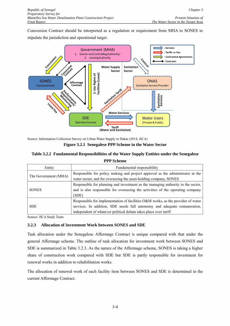
Republic of Senegal Chapter 3 Preparatory Survey for Mamelles Sea Water Desalination Plant Construction Project Present Situation of Final Report The Water Sector in the Target Area
Concession Contract should be interpreted as a regulation or requirement from MHA to SONES to stipulate the jurisdiction and operational target.
Source: Information Collection Survey on Urban Water Supply in Dakar (2014, JICA)
Figure 3.2.1 Senegalese PPP Scheme in the Water Sector
Table 3.2.2 Fundamental Responsibilities of the Water Supply Entities under the Senegalese PPP Scheme
Entity Fundamental responsibility
The Government (MHA) Responsible for policy making and project approval as the administrator in the water sector, and for overseeing the asset-holding company, SONES
SONES Responsible for planning and investment as the managing authority in the sector, and is also responsible for overseeing the activities of the operating company (SDE)
SDE Responsible for implementation of facilities O&M works, as the provider of water services. In addition, SDE needs full autonomy and adequate remuneration, independent of whatever political debate takes place over tariff
Source: JICA Study Team
3.2.3 Allocation of Investment Work between SONES and SDE
Task allocation under the Senegalese Affermage Contract is unique compared with that under the general Affermage scheme. The outline of task allocation for investment work between SONES and SDE is summarized in Table 3.2.3. As the nature of the Affermage scheme, SONES is taking a higher share of construction work compared with SDE but SDE is partly responsible for investment for renewal works in addition to rehabilitation works.
The allocation of renewal work of each facility item between SONES and SDE is determined in the current Affermage Contract.
Government (MHA)1. Owner and Controlling Authority/
2. Leasing Authority
SONESConcessionaire
SDEOperator/Lessee
ONASSanitation Service Provider
Water Users(Private & Public)
Water Services
Tariff (Water and Sanitation)
2. U
se R
ight
s of
Faci
litie
s (Le
ase)
Sani
tatio
n Se
rvic
es
Affermage Contract
Water Supply Sector
Sanitation Sector
: Services
: Contracted Agreements
: Tariffs or Fee
: Contracts
3-4
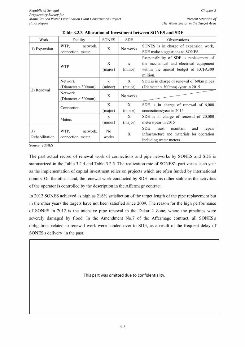
Republic of Senegal Chapter 3 Preparatory Survey for Mamelles Sea Water Desalination Plant Construction Project Present Situation of Final Report The Water Sector in the Target Area
Table 3.2.3 Allocation of Investment between SONES and SDE Work Facility SONES SDE Observations
1) Expansion WTP, network, connection, meter
X No works SONES is in charge of expansion work, SDE make suggestions to SONES
2) Renewal
WTP X
(major) x
(minor)
Responsibility of SDE is replacement of the mechanical and electrical equipment within the annual budget of F.CFA300 million.
Network (Diameter < 300mm)
x (minor)
X (major)
SDE is in charge of renewal of 60km pipes (Diameter < 300mm) /year in 2015
Network (Diameter > 300mm)
X No works
Connection X
(major) X
(minor) SDE is in charge of renewal of 6,000 connections/year in 2015
Meters x
(minor) X
(major) SDE is in charge of renewal of 20,000 meters/year in 2015
3) Rehabilitation
WTP, network, connection, meter
No works
X SDE must maintain and repair infrastructure and materials for operation including water meters.
Source: SONES
The past actual record of renewal work of connections and pipe networks by SONES and SDE is summarized in the Table 3.2.4 and Table 3.2.5. The realization rate of SONES's part varies each year as the implementation of capital investment relies on projects which are often funded by international donors. On the other hand, the renewal work conducted by SDE remains rather stable as the activities of the operator is controlled by the description in the Affermage contract.
In 2012 SONES achieved as high as 216% satisfaction of the target length of the pipe replacement but in the other years the targets have not been satisfied since 2009. The reason for the high performance of SONES in 2012 is the intensive pipe renewal in the Dakar 2 Zone, where the pipelines were severely damaged by flood. In the Amendment No.7 of the Affermage contract, all SONES's obligations related to renewal work were handed over to SDE, as a result of the frequent delay of SONES's delivery in the past.
This part was omitted due to confidentiality.
3-5
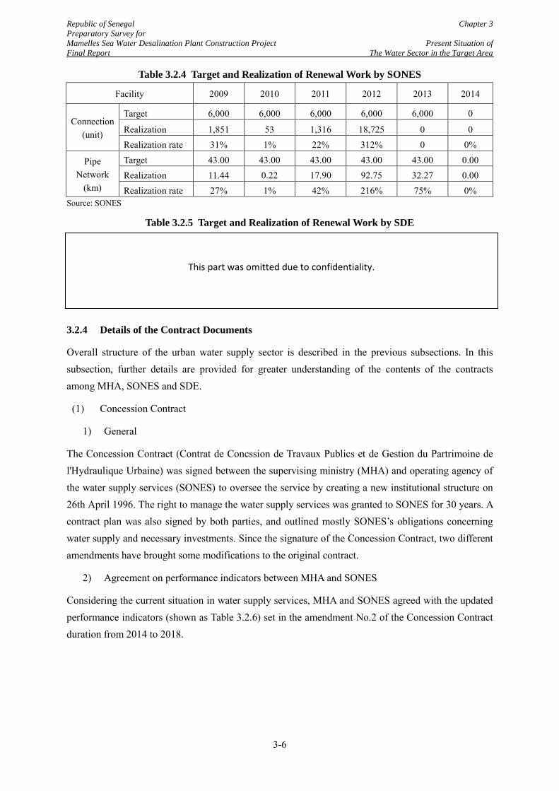
Republic of Senegal Chapter 3 Preparatory Survey for Mamelles Sea Water Desalination Plant Construction Project Present Situation of Final Report The Water Sector in the Target Area
Table 3.2.4 Target and Realization of Renewal Work by SONES
Facility 2009 2010 2011 2012 2013 2014
Connection (unit)
Target 6,000 6,000 6,000 6,000 6,000 0
Realization 1,851 53 1,316 18,725 0 0 Realization rate 31% 1% 22% 312% 0 0%
Pipe Network
(km)
Target 43.00 43.00 43.00 43.00 43.00 0.00 Realization 11.44 0.22 17.90 92.75 32.27 0.00 Realization rate 27% 1% 42% 216% 75% 0%
Source: SONES
Table 3.2.5 Target and Realization of Renewal Work by SDE
3.2.4 Details of the Contract Documents
Overall structure of the urban water supply sector is described in the previous subsections. In this subsection, further details are provided for greater understanding of the contents of the contracts among MHA, SONES and SDE.
(1) Concession Contract
1) General
The Concession Contract (Contrat de Concssion de Travaux Publics et de Gestion du Partrimoine de l'Hydraulique Urbaine) was signed between the supervising ministry (MHA) and operating agency of the water supply services (SONES) to oversee the service by creating a new institutional structure on 26th April 1996. The right to manage the water supply services was granted to SONES for 30 years. A contract plan was also signed by both parties, and outlined mostly SONES’s obligations concerning water supply and necessary investments. Since the signature of the Concession Contract, two different amendments have brought some modifications to the original contract.
2) Agreement on performance indicators between MHA and SONES
Considering the current situation in water supply services, MHA and SONES agreed with the updated performance indicators (shown as Table 3.2.6) set in the amendment No.2 of the Concession Contract duration from 2014 to 2018.
This part was omitted due to confidentiality.
3-6
Republic of Senegal Chapter 3 Preparatory Survey for Mamelles Sea Water Desalination Plant Construction Project Present Situation of Final Report The Water Sector in the Target Area
Table 3.2.6 Performance Indicators between MHA & SONES Indicators 2014 2015 2016 2017 2018
Water production (thousand m3/year) 164,037 169,695 174,223 178,366 182.687 Billed volume(thousand m3/year) 131,722 137,062 141,469 145,368 148.890 Produced water volume that does not satisfy WHO standard in terms of physicochemical characteristics (thousand m3/year)
32 32 32 18 18
Number of WTP operated and maintained 76 76 76 76 76 Number of service connections 552,359 574,029 595,699 617,369 639,039 Served population (No. of people) 5,491,592 5,621,529 5,754,552 5,890,736 6,030,155 Water access (%) 94.2 99.4 99.4 99.4 99.6 Financial debt Amount (Million CFCA) 83,614 84,913 97,795 108,439 102,039 Interest Payment (Million CFCA) 3,332 3,071 3,415 3,130 2,705 Reimbursement (Million CFCA) 5,393 7,741 8,079 8,090 8,400 Investment placed (Million CFCA) 17,627 9,434 27,156 19,968 2,400 Water consumption by administration and universities (m3/ year)
11.17 11.39 11.55 11.69 11.79
Water consumption in agriculture (m3/day) 12,000 12,000 12,000 12,000 12,000 Average water rate including sanitation and taxes per cubic meter(CFCA)
613.98 617.67 621.53 621.65 621.21
Source: Amendment No.2 of the Concession Contract
3) Urban Hydraulic Master Plan and implementation of a Five-year Investment Program
Besides the fact that programs such as the ‘Long-term Water Project or Millennium Program for Drinking Water and Sanitation (PEPAM)’, has made Senegal one of the West African Countries with the highest drinking water access, the country is still facing challenges in urban areas. The Senegalese Government came up with a plan called ‘The Urban Hydraulics Master Plan’ whose goal is to improve the water supply sector in urban areas and eventually eradicate deficits in water supply in urban areas. MHA and SONES are implementing the five-year investment program (2013-2018), which is a breakdown of the investment of all the projects that are part of the Urban Hydraulic Master Plan, over five year, using loans, subsidies and their own funds.
4) Water provision for agricultural purposes and water resources development
Water supply for agricultural purposes and the security of water resources are the responsibilities of SONES. As for the agricultural water, the following agreements are described in the Concession Contract:
Agricultural consumption will be limited to 12,000 m3/day after ground water from Thiaroye and recycled water from Cambérène wastewater treatment plant are supplemented.
Alternative ways such as wastewater and groundwater are used for irrigation in order to decrease the volume of irrigational water taken from the water supply system for urban areas.
3-7
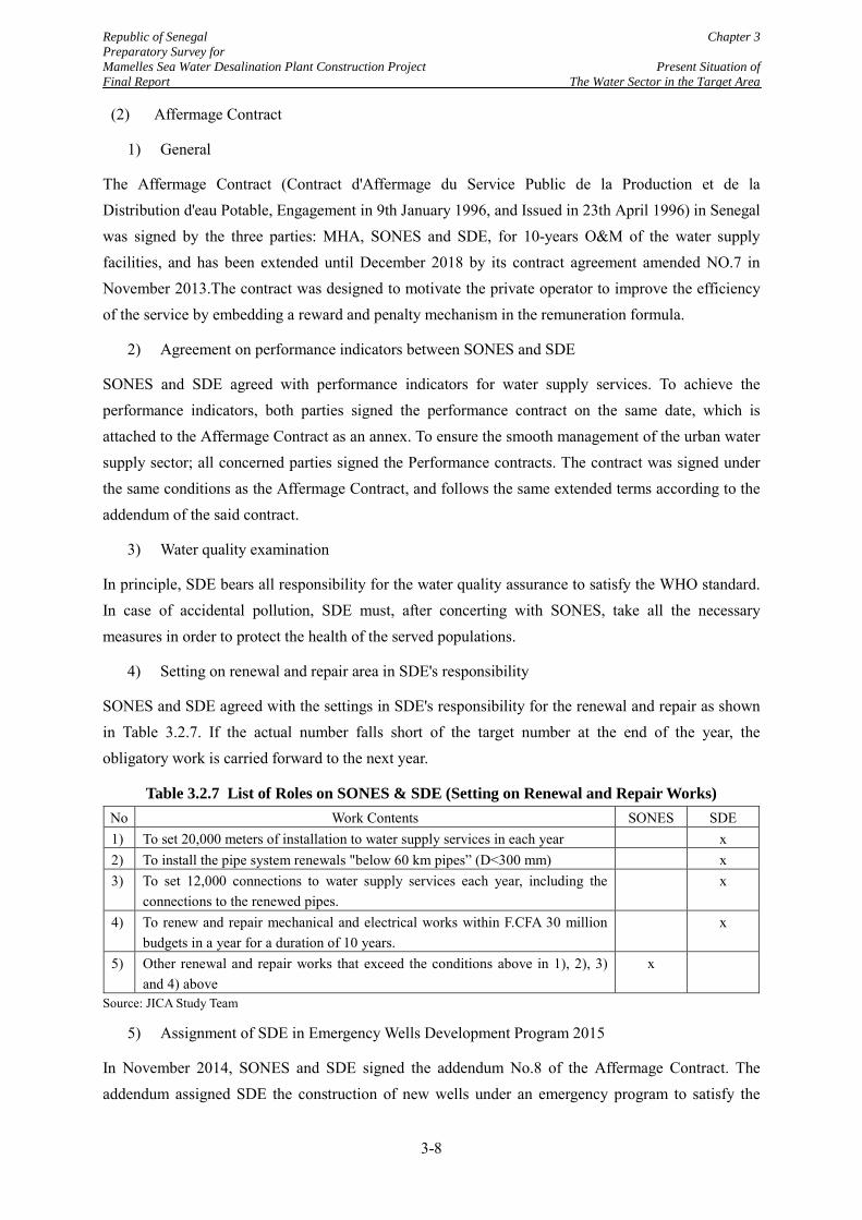
Republic of Senegal Chapter 3 Preparatory Survey for Mamelles Sea Water Desalination Plant Construction Project Present Situation of Final Report The Water Sector in the Target Area
(2) Affermage Contract
1) General
The Affermage Contract (Contract d'Affermage du Service Public de la Production et de la Distribution d'eau Potable, Engagement in 9th January 1996, and Issued in 23th April 1996) in Senegal was signed by the three parties: MHA, SONES and SDE, for 10-years O&M of the water supply facilities, and has been extended until December 2018 by its contract agreement amended NO.7 in November 2013.The contract was designed to motivate the private operator to improve the efficiency of the service by embedding a reward and penalty mechanism in the remuneration formula.
2) Agreement on performance indicators between SONES and SDE
SONES and SDE agreed with performance indicators for water supply services. To achieve the performance indicators, both parties signed the performance contract on the same date, which is attached to the Affermage Contract as an annex. To ensure the smooth management of the urban water supply sector; all concerned parties signed the Performance contracts. The contract was signed under the same conditions as the Affermage Contract, and follows the same extended terms according to the addendum of the said contract.
3) Water quality examination
In principle, SDE bears all responsibility for the water quality assurance to satisfy the WHO standard. In case of accidental pollution, SDE must, after concerting with SONES, take all the necessary measures in order to protect the health of the served populations.
4) Setting on renewal and repair area in SDE's responsibility
SONES and SDE agreed with the settings in SDE's responsibility for the renewal and repair as shown in Table 3.2.7. If the actual number falls short of the target number at the end of the year, the obligatory work is carried forward to the next year.
Table 3.2.7 List of Roles on SONES & SDE (Setting on Renewal and Repair Works) No Work Contents SONES SDE 1) To set 20,000 meters of installation to water supply services in each year x 2) To install the pipe system renewals "below 60 km pipes” (D<300 mm) x 3) To set 12,000 connections to water supply services each year, including the
connections to the renewed pipes. x
4) To renew and repair mechanical and electrical works within F.CFA 30 million budgets in a year for a duration of 10 years.
x
5) Other renewal and repair works that exceed the conditions above in 1), 2), 3) and 4) above
x
Source: JICA Study Team
5) Assignment of SDE in Emergency Wells Development Program 2015
In November 2014, SONES and SDE signed the addendum No.8 of the Affermage Contract. The addendum assigned SDE the construction of new wells under an emergency program to satisfy the
3-8
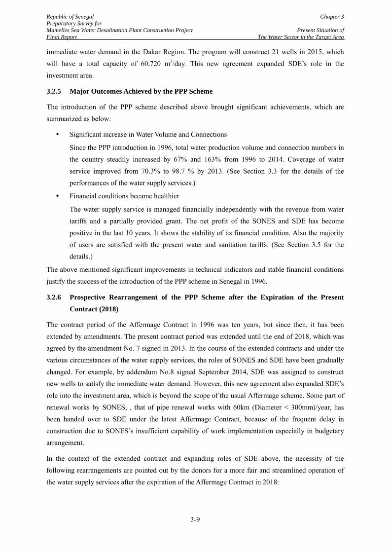
Republic of Senegal Chapter 3 Preparatory Survey for Mamelles Sea Water Desalination Plant Construction Project Present Situation of Final Report The Water Sector in the Target Area
immediate water demand in the Dakar Region. The program will construct 21 wells in 2015, which will have a total capacity of 60,720 m3/day. This new agreement expanded SDE’s role in the investment area.
3.2.5 Major Outcomes Achieved by the PPP Scheme
The introduction of the PPP scheme described above brought significant achievements, which are summarized as below:
Significant increase in Water Volume and Connections
Since the PPP introduction in 1996, total water production volume and connection numbers in the country steadily increased by 67% and 163% from 1996 to 2014. Coverage of water service improved from 70.3% to 98.7 % by 2013. (See Section 3.3 for the details of the performances of the water supply services.)
Financial conditions became healthier
The water supply service is managed financially independently with the revenue from water tariffs and a partially provided grant. The net profit of the SONES and SDE has become positive in the last 10 years. It shows the stability of its financial condition. Also the majority of users are satisfied with the present water and sanitation tariffs. (See Section 3.5 for the details.)
The above mentioned significant improvements in technical indicators and stable financial conditions justify the success of the introduction of the PPP scheme in Senegal in 1996.
3.2.6 Prospective Rearrangement of the PPP Scheme after the Expiration of the Present Contract (2018)
The contract period of the Affermage Contract in 1996 was ten years, but since then, it has been extended by amendments. The present contract period was extended until the end of 2018, which was agreed by the amendment No. 7 signed in 2013. In the course of the extended contracts and under the various circumstances of the water supply services, the roles of SONES and SDE have been gradually changed. For example, by addendum No.8 signed September 2014, SDE was assigned to construct new wells to satisfy the immediate water demand. However, this new agreement also expanded SDE’s role into the investment area, which is beyond the scope of the usual Affermage scheme. Some part of renewal works by SONES, , that of pipe renewal works with 60km (Diameter < 300mm)/year, has been handed over to SDE under the latest Affermage Contract, because of the frequent delay in construction due to SONES’s insufficient capability of work implementation especially in budgetary arrangement.
In the context of the extended contract and expanding roles of SDE above, the necessity of the following rearrangements are pointed out by the donors for a more fair and streamlined operation of the water supply services after the expiration of the Affermage Contract in 2018:
3-9
Republic of Senegal Chapter 3 Preparatory Survey for Mamelles Sea Water Desalination Plant Construction Project Present Situation of Final Report The Water Sector in the Target Area
A New bid would be conducted to select a new operator. (SDE can be one of the bidders)
The content of the Affermage scheme would be modified to clarify the rights and responsibilities of SONES and the private operator
According to SONES, the implementation structure after 2018 is under consideration, and a final decision will be made politically before the expiration of the contract.
3.2.7 Organizational Structures of the Relevant Entities
(1) Organizational Structure of SONES
Figure 3.2.2 shows organizational structure of SONES. The number of staff in SONES was 103 as of February 2015, which is larger than that in 2014 by 1 person. Direction of Studies and Planning is in charge of studies and planning of new projects including this desalination project. Direction of Works is in charge of project management including construction supervision. Direction of Control and Operation is in charge of instruction to SDE for operation and maintenance (O&M) works of water treatment plants (WTPs), water transmission pipes and other water supply facilities.
SONES, who is a state-owned company, is required to submit Financial Report every year and Technical Report in every 3 months to MHA, who is the controlling agency of SONES. Reviewing the reports, MHA provides instructions or advices to SONES, when necessary. Nevertheless, SONES has an authorized power to independently make decisions on their administrative matters, including budget and personnel issues.
Source: SONES
Figure 3.2.2 Organizational Structure of SONES (As of February 2015)
3-10
Republic of Senegal Chapter 3 Preparatory Survey for Mamelles Sea Water Desalination Plant Construction Project Present Situation of Final Report The Water Sector in the Target Area
(2) Organizational Structure of SDE
SDE is a private company which is registered under the procedure of the Senegalese Notarial Acts.
Table 3.2.8 Shareholder Composition of SDE
Figure 3.2.3 Organizational Structure of SDE (As of February 2015)
This part was omitted due to confidentiality.
This part was omitted due to confidentiality.
3-11
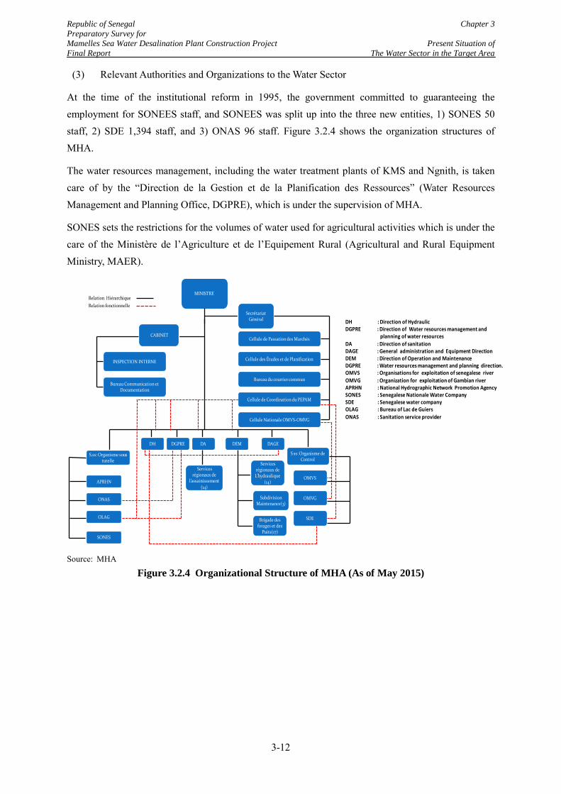
Republic of Senegal Chapter 3 Preparatory Survey for Mamelles Sea Water Desalination Plant Construction Project Present Situation of Final Report The Water Sector in the Target Area
(3) Relevant Authorities and Organizations to the Water Sector
At the time of the institutional reform in 1995, the government committed to guaranteeing the employment for SONEES staff, and SONEES was split up into the three new entities, 1) SONES 50 staff, 2) SDE 1,394 staff, and 3) ONAS 96 staff. Figure 3.2.4 shows the organization structures of MHA.
The water resources management, including the water treatment plants of KMS and Ngnith, is taken care of by the “Direction de la Gestion et de la Planification des Ressources” (Water Resources Management and Planning Office, DGPRE), which is under the supervision of MHA.
SONES sets the restrictions for the volumes of water used for agricultural activities which is under the care of the Ministère de l’Agriculture et de l’Equipement Rural (Agricultural and Rural Equipment Ministry, MAER).
Source: MHA
Figure 3.2.4 Organizational Structure of MHA (As of May 2015)
MINISTRE
Secrétariat Général
Cellule de Passation des Marchés
Cellule Nationale OMVS-OMVG
Cellule des Études et de Planification
Bureau du courrier commun
Cellule de Coordination du PEPAM
CABINET
INSPECTION INTERNE
Bureau Communication et Documentation
APRHN
ONAS
OLAG
SONES
S.ss: Organisme sous tutelle
S ss: Organisme de Control
DH DGPRE DA DEM DAGE
OMVS
OMVG
SDE
Services régionaux de L’hydraulique
(14)
Subdivision Maintenance(3)
Brigade des forages et des
Puits(17)
Services régionaux de
l’assainissement(14)
Relation Hiérarchique Relation fonctionnelle
DH : Direction of HydraulicDGPRE : Direction of Water resources management and
planning of water resourcesDA : Direction of sanitationDAGE : General administration and Equipment Direction DEM : Direction of Operation and Maintenance DGPRE : Water resources management and planning direction.OMVS : Organisations for exploitation of senegalese river OMVG : Organization for exploitation of Gambian river APRHN : National Hydrographic Network Promotion Agency SONES : Senegalese Nationale Water Company SDE : Senegalese water company OLAG : Bureau of Lac de Guiers ONAS : Sanitation service provider
3-12
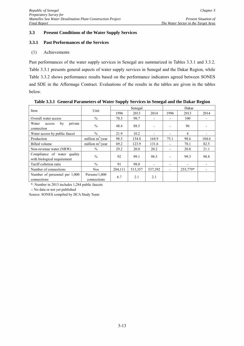
Republic of Senegal Chapter 3 Preparatory Survey for Mamelles Sea Water Desalination Plant Construction Project Present Situation of Final Report The Water Sector in the Target Area
3.3 Present Conditions of the Water Supply Services
3.3.1 Past Performances of the Services
(1) Achievements
Past performances of the water supply services in Senegal are summarized in Tables 3.3.1 and 3.3.2. Table 3.3.1 presents general aspects of water supply services in Senegal and the Dakar Region, while Table 3.3.2 shows performance results based on the performance indicators agreed between SONES and SDE in the Affermage Contract. Evaluations of the results in the tables are given in the tables below.
Table 3.3.1 General Parameters of Water Supply Services in Senegal and the Dakar Region
Item Unit Senegal Dakar
1996 2013 2014 1996 2013 2014 Overall water access % 70.3 98.7 - - 100 - Water access by private connection
% 48.4 88.5 - - 96 -
Water access by public faucet % 21.9 10.2 - - 4 - Production million m3/year 98.5 154.8 164.9 75.1 98.6 104.6 Billed volume million m3/year 69.2 123.9 131.6 - 78.1 82.5 Non-revenue water (NRW) % 29.2 20.0 20.2 - 20.8 21.1 Compliance of water quality with biological requirement
% 92 99.1 98.5 - 99.3 98.8
Tariff colletion ratio % 91 98.0 - - - - Number of connections Nos 204,111 513,357 537,392 - 255,779* - Number of personnel per 1,000 connections
Persons/1,000 connections
6.7 2.1 2.1
*: Number in 2013 includes 1,284 public faucets
-: No data or not yet published
Source: SONES compiled by JICA Study Team
3-13
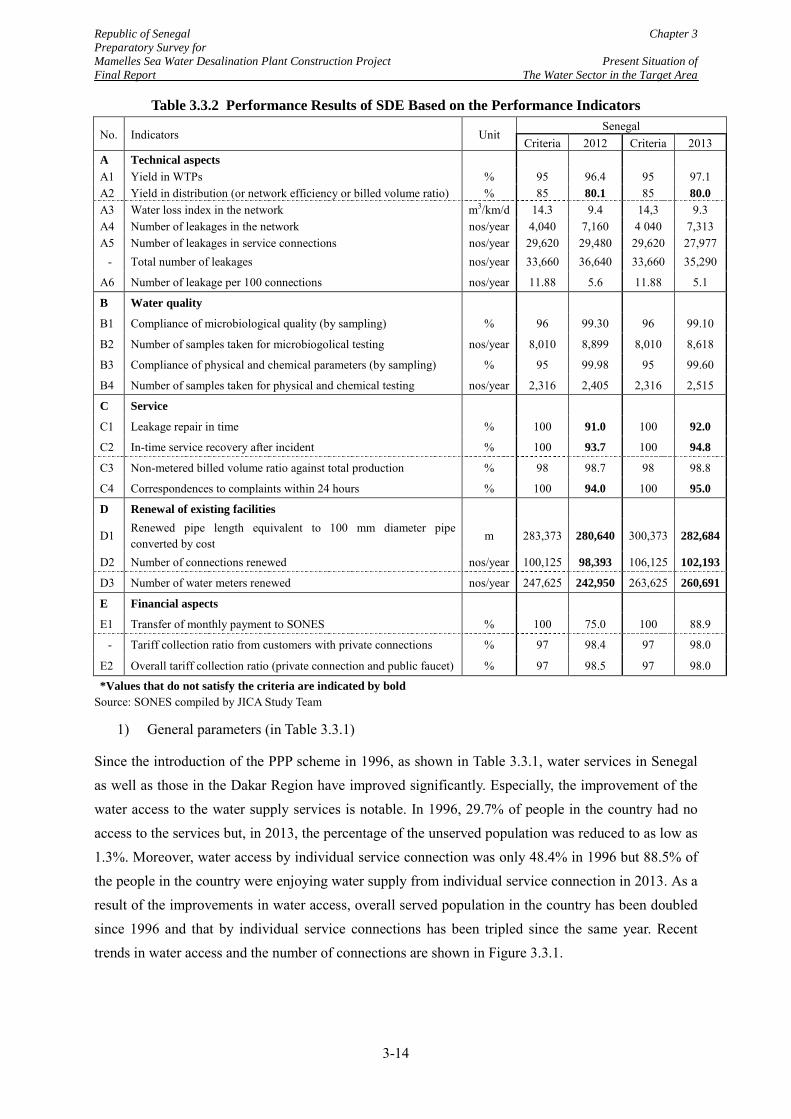
Republic of Senegal Chapter 3 Preparatory Survey for Mamelles Sea Water Desalination Plant Construction Project Present Situation of Final Report The Water Sector in the Target Area
Table 3.3.2 Performance Results of SDE Based on the Performance Indicators
No. Indicators Unit Senegal
Criteria 2012 Criteria 2013 A Technical aspects
A1 Yield in WTPs % 95 96.4 95 97.1 A2 Yield in distribution (or network efficiency or billed volume ratio) % 85 80.1 85 80.0 A3 Water loss index in the network m3/km/d 14.3 9.4 14,3 9.3 A4 Number of leakages in the network nos/year 4,040 7,160 4 040 7,313 A5 Number of leakages in service connections nos/year 29,620 29,480 29,620 27,977 - Total number of leakages nos/year 33,660 36,640 33,660 35,290
A6 Number of leakage per 100 connections nos/year 11.88 5.6 11.88 5.1
B Water quality
B1 Compliance of microbiological quality (by sampling) % 96 99.30 96 99.10
B2 Number of samples taken for microbiogolical testing nos/year 8,010 8,899 8,010 8,618
B3 Compliance of physical and chemical parameters (by sampling) % 95 99.98 95 99.60
B4 Number of samples taken for physical and chemical testing nos/year 2,316 2,405 2,316 2,515
C Service
C1 Leakage repair in time % 100 91.0 100 92.0
C2 In-time service recovery after incident % 100 93.7 100 94.8
C3 Non-metered billed volume ratio against total production % 98 98.7 98 98.8
C4 Correspondences to complaints within 24 hours % 100 94.0 100 95.0
D Renewal of existing facilities
D1 Renewed pipe length equivalent to 100 mm diameter pipe converted by cost
m 283,373 280,640 300,373 282,684
D2 Number of connections renewed nos/year 100,125 98,393 106,125 102,193
D3 Number of water meters renewed nos/year 247,625 242,950 263,625 260,691
E Financial aspects
E1 Transfer of monthly payment to SONES % 100 75.0 100 88.9
- Tariff collection ratio from customers with private connections % 97 98.4 97 98.0
E2 Overall tariff collection ratio (private connection and public faucet) % 97 98.5 97 98.0
*Values that do not satisfy the criteria are indicated by bold Source: SONES compiled by JICA Study Team
1) General parameters (in Table 3.3.1)
Since the introduction of the PPP scheme in 1996, as shown in Table 3.3.1, water services in Senegal as well as those in the Dakar Region have improved significantly. Especially, the improvement of the water access to the water supply services is notable. In 1996, 29.7% of people in the country had no access to the services but, in 2013, the percentage of the unserved population was reduced to as low as 1.3%. Moreover, water access by individual service connection was only 48.4% in 1996 but 88.5% of the people in the country were enjoying water supply from individual service connection in 2013. As a result of the improvements in water access, overall served population in the country has been doubled since 1996 and that by individual service connections has been tripled since the same year. Recent trends in water access and the number of connections are shown in Figure 3.3.1.
3-14
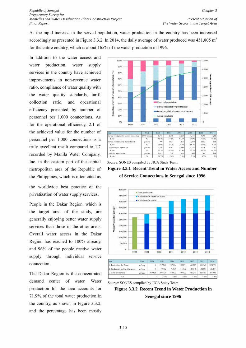
Republic of Senegal Chapter 3 Preparatory Survey for Mamelles Sea Water Desalination Plant Construction Project Present Situation of Final Report The Water Sector in the Target Area
As the rapid increase in the served population, water production in the country has been increased accordingly as presented in Figure 3.3.2. In 2014, the daily average of water produced was 451,805 m3 for the entire country, which is about 165% of the water production in 1996.
In addition to the water access and water production, water supply services in the country have achieved improvements in non-revenue water ratio, compliance of water quality with the water quality standards, tariff collection ratio, and operational efficiency presented by number of personnel per 1,000 connections. As for the operational efficiency, 2.1 of the achieved value for the number of personnel per 1,000 connections is a truly excellent result compared to 1.7 recorded by Manila Water Company, Inc. in the eastern part of the capital metropolitan area of the Republic of the Philippines, which is often cited as
the worldwide best practice of the privatization of water supply services.
People in the Dakar Region, which is the target area of the study, are generally enjoying better water supply services than those in the other areas. Overall water access in the Dakar Region has reached to 100% already, and 96% of the people receive water supply through individual service connection.
The Dakar Region is the concentrated demand center of water. Water production for the area accounts for 71.9% of the total water production in the country, as shown in Figure 3.3.2, and the percentage has been mostly
Source: SONES compiled by JICA Study Team
Figure 3.3.1 Recent Trend in Water Access and Number of Service Connections in Senegal since 1996
Item Unit 1996 2001 2006 2011 2012 2013Served population by service connection 1,000 person 1,746 2,376 3,207 4,114 4,398 5,256 Ratio % 48.4% 57.6% 67.6% 74.0% 76.9% 88.5%Served population by public faucet person 790 1,031 1,177 1,040 1,052 506 Ratio % 21.9% 25.0% 24.8% 18.7% 18.4% 10.2%Overall served population person 2,536 3,407 4,384 5,153 5,450 5,762 Ratio % 70.3% 82.6% 92.4% 92.7% 95.3% 98.7%Unserved popualation person 1,072 718 361 406 269 118 Ratio % 29.7% 17.4% 7.6% 7.3% 4.7% 1.3%
Source: SONES compiled by JICA Study Team
Figure 3.3.2 Recent Trend in Water Production in Senegal since 1996
Item Unit 1996 2001 2006 2011 2012 2013 2014
A. Production for Dakar m3/day 0 217,268 257,184 295,191 301,227 301,562 324,931
B. Production for the other areas m3/day 0 77,462 96,839 111,932 120,118 122,591 126,874
C. Total production m3/day 269,835 294,729 354,022 407,123 421,344 424,153 451,805
A/C - - 73.7% 72.6% 72.5% 71.5% 71.1% 71.9%
3-15
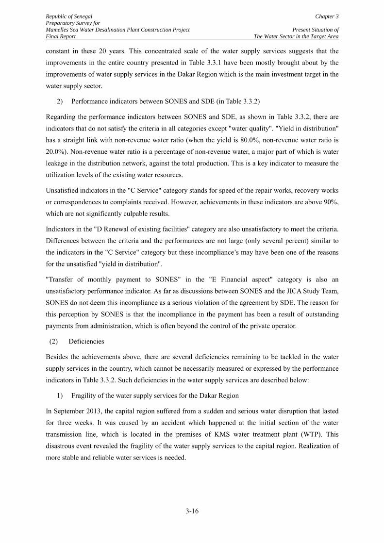
Republic of Senegal Chapter 3 Preparatory Survey for Mamelles Sea Water Desalination Plant Construction Project Present Situation of Final Report The Water Sector in the Target Area
constant in these 20 years. This concentrated scale of the water supply services suggests that the improvements in the entire country presented in Table 3.3.1 have been mostly brought about by the improvements of water supply services in the Dakar Region which is the main investment target in the water supply sector.
2) Performance indicators between SONES and SDE (in Table 3.3.2)
Regarding the performance indicators between SONES and SDE, as shown in Table 3.3.2, there are indicators that do not satisfy the criteria in all categories except "water quality". "Yield in distribution" has a straight link with non-revenue water ratio (when the yield is 80.0%, non-revenue water ratio is 20.0%). Non-revenue water ratio is a percentage of non-revenue water, a major part of which is water leakage in the distribution network, against the total production. This is a key indicator to measure the utilization levels of the existing water resources.
Unsatisfied indicators in the "C Service" category stands for speed of the repair works, recovery works or correspondences to complaints received. However, achievements in these indicators are above 90%, which are not significantly culpable results.
Indicators in the "D Renewal of existing facilities" category are also unsatisfactory to meet the criteria. Differences between the criteria and the performances are not large (only several percent) similar to the indicators in the "C Service" category but these incompliance’s may have been one of the reasons for the unsatisfied "yield in distribution".
"Transfer of monthly payment to SONES" in the "E Financial aspect" category is also an unsatisfactory performance indicator. As far as discussions between SONES and the JICA Study Team, SONES do not deem this incompliance as a serious violation of the agreement by SDE. The reason for this perception by SONES is that the incompliance in the payment has been a result of outstanding payments from administration, which is often beyond the control of the private operator.
(2) Deficiencies
Besides the achievements above, there are several deficiencies remaining to be tackled in the water supply services in the country, which cannot be necessarily measured or expressed by the performance indicators in Table 3.3.2. Such deficiencies in the water supply services are described below:
1) Fragility of the water supply services for the Dakar Region
In September 2013, the capital region suffered from a sudden and serious water disruption that lasted for three weeks. It was caused by an accident which happened at the initial section of the water transmission line, which is located in the premises of KMS water treatment plant (WTP). This disastrous event revealed the fragility of the water supply services to the capital region. Realization of more stable and reliable water services is needed.
3-16
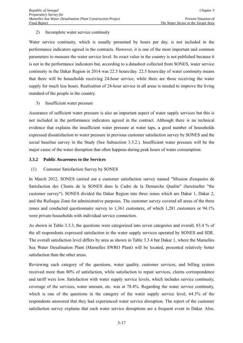
Republic of Senegal Chapter 3 Preparatory Survey for Mamelles Sea Water Desalination Plant Construction Project Present Situation of Final Report The Water Sector in the Target Area
2) Incomplete water service continuity
Water service continuity, which is usually presented by hours per day, is not included in the performance indicators agreed in the contracts. However, it is one of the most important and common parameters to measure the water service level. Its exact value in the country is not published because it is not in the performance indicators but, according to a datasheet collected from SONES, water service continuity in the Dakar Region in 2014 was 22.5 hours/day. 22.5 hours/day of water continuity means that there will be households receiving 24-hour service, while there are those receiving the water supply for much less hours. Realization of 24-hour service in all areas is needed to improve the living standard of the people in the country.
3) Insufficient water pressure
Assurance of sufficient water pressure is also an important aspect of water supply services but this is not included in the performance indicators agreed in the contract. Although there is no technical evidence that explains the insufficient water pressure at water taps, a good number of households expressed dissatisfaction to water pressure in previous customer satisfaction survey by SONES and the social baseline survey in the Study (See Subsection 3.3.2.). Insufficient water pressure will be the major cause of the water disruption that often happens during peak hours of water consumption.
3.3.2 Public Awareness to the Services
(1) Customer Satisfaction Survey by SONES
In March 2012, SONES carried out a customer satisfaction survey named "Mission d'enquetes de Satisfaction des Clients de la SONES dans le Cadre de la Demarche Qualite" (hereinafter "the customer survey"). SONES divided the Dakar Region into three zones which are Dakar 1, Dakar 2, and the Rufisque Zone for administrative purposes. The customer survey covered all areas of the three zones and conducted questionnaire survey to 1,361 customers, of which 1,281 customers or 94.1% were private households with individual service connection.
As shown in Table 3.3.3, the questions were categorized into seven categories and overall, 83.4 % of the all respondents expressed satisfaction to the water supply services operated by SONES and SDE. The overall satisfaction level differs by area as shown in Table 3.3.4 but Dakar 1, where the Mamelles Sea Water Desalination Plant (Mamelles SWRO Plant) will be located, presented relatively better satisfaction than the other areas.
Reviewing each category of the questions, water quality, customer services, and billing system received more than 80% of satisfaction, while satisfaction to repair services, claims correspondence and tariff were low. Satisfaction with water supply service levels, which includes service continuity, coverage of the services, water amount, etc. was at 78.4%. Regarding the water service continuity, which is one of the questions in the category of the water supply service level, 64.3% of the respondents answered that they had experienced water service disruption. The report of the customer satisfaction survey explains that such water service disruptions are a frequent event in Dakar. Also,
3-17
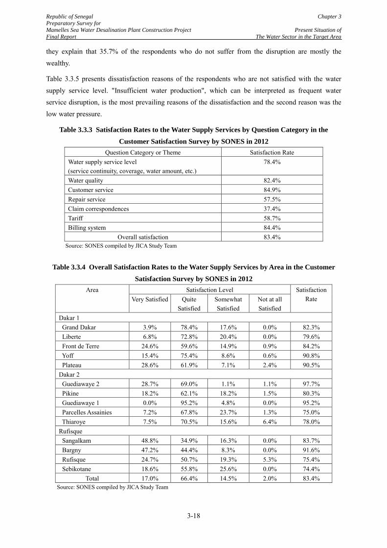
Republic of Senegal Chapter 3 Preparatory Survey for Mamelles Sea Water Desalination Plant Construction Project Present Situation of Final Report The Water Sector in the Target Area
they explain that 35.7% of the respondents who do not suffer from the disruption are mostly the wealthy.
Table 3.3.5 presents dissatisfaction reasons of the respondents who are not satisfied with the water supply service level. "Insufficient water production", which can be interpreted as frequent water service disruption, is the most prevailing reasons of the dissatisfaction and the second reason was the low water pressure.
Table 3.3.3 Satisfaction Rates to the Water Supply Services by Question Category in the Customer Satisfaction Survey by SONES in 2012
Question Category or Theme Satisfaction Rate Water supply service level (service continuity, coverage, water amount, etc.)
78.4%
Water quality 82.4% Customer service 84.9% Repair service 57.5% Claim correspondences 37.4% Tariff 58.7% Billing system 84.4%
Overall satisfaction 83.4% Source: SONES compiled by JICA Study Team
Table 3.3.4 Overall Satisfaction Rates to the Water Supply Services by Area in the Customer Satisfaction Survey by SONES in 2012
Area Satisfaction Level Satisfaction Rate Very Satisfied Quite
Satisfied Somewhat Satisfied
Not at all Satisfied
Dakar 1 Grand Dakar 3.9% 78.4% 17.6% 0.0% 82.3% Liberte 6.8% 72.8% 20.4% 0.0% 79.6% Front de Terre 24.6% 59.6% 14.9% 0.9% 84.2% Yoff 15.4% 75.4% 8.6% 0.6% 90.8% Plateau 28.6% 61.9% 7.1% 2.4% 90.5% Dakar 2 Guediawaye 2 28.7% 69.0% 1.1% 1.1% 97.7% Pikine 18.2% 62.1% 18.2% 1.5% 80.3% Guediawaye 1 0.0% 95.2% 4.8% 0.0% 95.2% Parcelles Assainies 7.2% 67.8% 23.7% 1.3% 75.0% Thiaroye 7.5% 70.5% 15.6% 6.4% 78.0% Rufisque Sangalkam 48.8% 34.9% 16.3% 0.0% 83.7% Bargny 47.2% 44.4% 8.3% 0.0% 91.6% Rufisque 24.7% 50.7% 19.3% 5.3% 75.4% Sebikotane 18.6% 55.8% 25.6% 0.0% 74.4%
Total 17.0% 66.4% 14.5% 2.0% 83.4% Source: SONES compiled by JICA Study Team
3-18
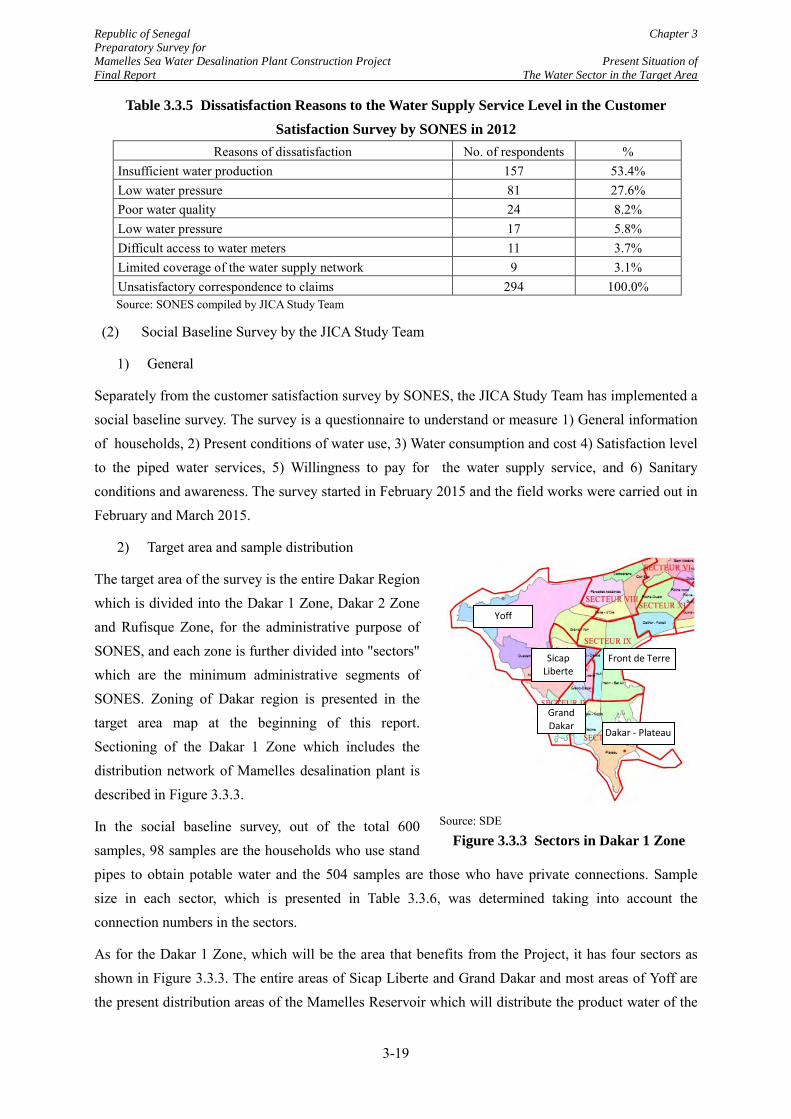
Republic of Senegal Chapter 3 Preparatory Survey for Mamelles Sea Water Desalination Plant Construction Project Present Situation of Final Report The Water Sector in the Target Area
Table 3.3.5 Dissatisfaction Reasons to the Water Supply Service Level in the Customer Satisfaction Survey by SONES in 2012
Reasons of dissatisfaction No. of respondents % Insufficient water production 157 53.4% Low water pressure 81 27.6% Poor water quality 24 8.2% Low water pressure 17 5.8% Difficult access to water meters 11 3.7% Limited coverage of the water supply network 9 3.1% Unsatisfactory correspondence to claims 294 100.0% Source: SONES compiled by JICA Study Team
(2) Social Baseline Survey by the JICA Study Team
1) General
Separately from the customer satisfaction survey by SONES, the JICA Study Team has implemented a social baseline survey. The survey is a questionnaire to understand or measure 1) General information of households, 2) Present conditions of water use, 3) Water consumption and cost 4) Satisfaction level to the piped water services, 5) Willingness to pay for the water supply service, and 6) Sanitary conditions and awareness. The survey started in February 2015 and the field works were carried out in February and March 2015.
2) Target area and sample distribution
The target area of the survey is the entire Dakar Region which is divided into the Dakar 1 Zone, Dakar 2 Zone and Rufisque Zone, for the administrative purpose of SONES, and each zone is further divided into "sectors" which are the minimum administrative segments of SONES. Zoning of Dakar region is presented in the target area map at the beginning of this report. Sectioning of the Dakar 1 Zone which includes the distribution network of Mamelles desalination plant is described in Figure 3.3.3.
In the social baseline survey, out of the total 600 samples, 98 samples are the households who use stand pipes to obtain potable water and the 504 samples are those who have private connections. Sample size in each sector, which is presented in Table 3.3.6, was determined taking into account the connection numbers in the sectors.
As for the Dakar 1 Zone, which will be the area that benefits from the Project, it has four sectors as shown in Figure 3.3.3. The entire areas of Sicap Liberte and Grand Dakar and most areas of Yoff are the present distribution areas of the Mamelles Reservoir which will distribute the product water of the
Source: SDE
Figure 3.3.3 Sectors in Dakar 1 Zone
Sicap Liberte
Front de Terre
Dakar - Plateau
Grand Dakar
Yoff
3-19
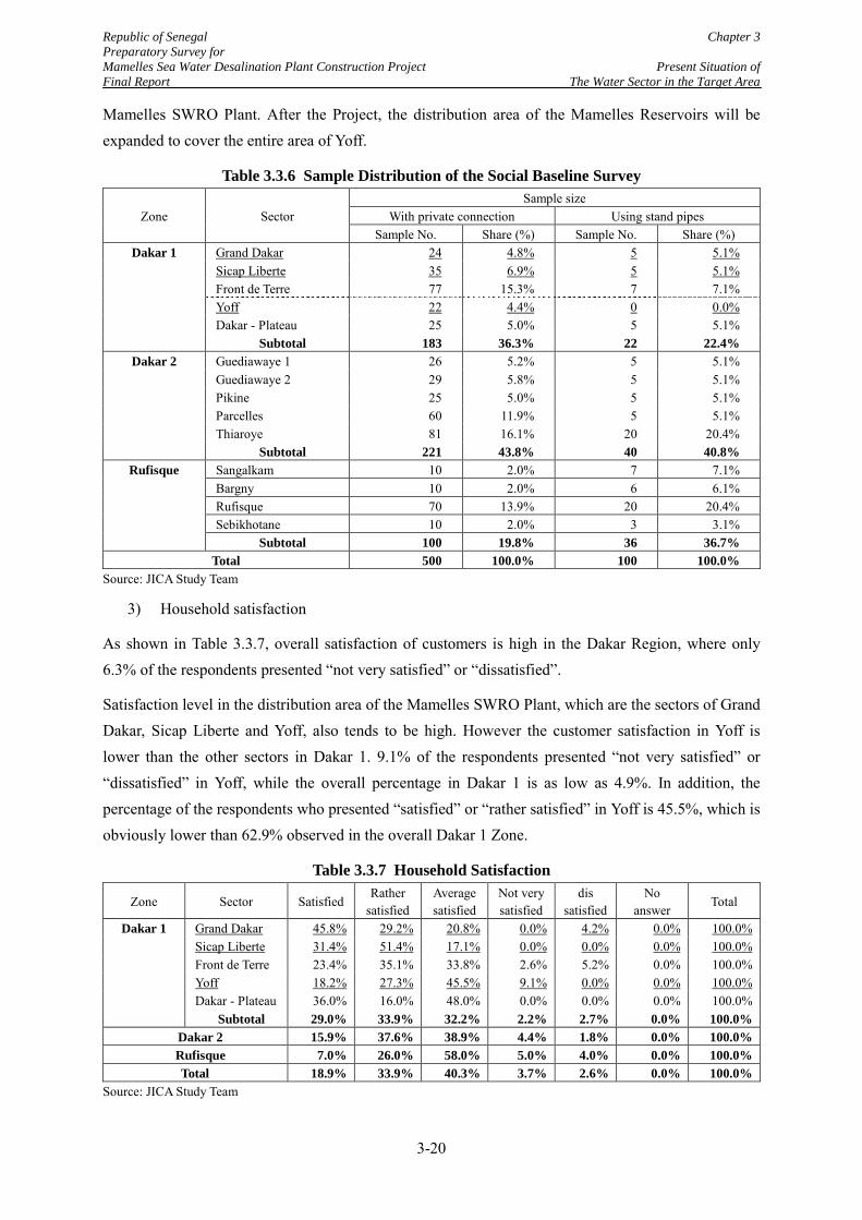
Republic of Senegal Chapter 3 Preparatory Survey for Mamelles Sea Water Desalination Plant Construction Project Present Situation of Final Report The Water Sector in the Target Area
Mamelles SWRO Plant. After the Project, the distribution area of the Mamelles Reservoirs will be expanded to cover the entire area of Yoff.
Table 3.3.6 Sample Distribution of the Social Baseline Survey
Zone Sector Sample size
With private connection Using stand pipes Sample No. Share (%) Sample No. Share (%)
Dakar 1 Grand Dakar 24 4.8% 5 5.1% Sicap Liberte 35 6.9% 5 5.1% Front de Terre 77 15.3% 7 7.1% Yoff 22 4.4% 0 0.0% Dakar - Plateau 25 5.0% 5 5.1%
Subtotal 183 36.3% 22 22.4% Dakar 2 Guediawaye 1 26 5.2% 5 5.1%
Guediawaye 2 29 5.8% 5 5.1% Pikine 25 5.0% 5 5.1% Parcelles 60 11.9% 5 5.1% Thiaroye 81 16.1% 20 20.4%
Subtotal 221 43.8% 40 40.8% Rufisque Sangalkam 10 2.0% 7 7.1%
Bargny 10 2.0% 6 6.1% Rufisque 70 13.9% 20 20.4% Sebikhotane 10 2.0% 3 3.1%
Subtotal 100 19.8% 36 36.7% Total 500 100.0% 100 100.0%
Source: JICA Study Team
3) Household satisfaction
As shown in Table 3.3.7, overall satisfaction of customers is high in the Dakar Region, where only 6.3% of the respondents presented “not very satisfied” or “dissatisfied”.
Satisfaction level in the distribution area of the Mamelles SWRO Plant, which are the sectors of Grand Dakar, Sicap Liberte and Yoff, also tends to be high. However the customer satisfaction in Yoff is lower than the other sectors in Dakar 1. 9.1% of the respondents presented “not very satisfied” or “dissatisfied” in Yoff, while the overall percentage in Dakar 1 is as low as 4.9%. In addition, the percentage of the respondents who presented “satisfied” or “rather satisfied” in Yoff is 45.5%, which is obviously lower than 62.9% observed in the overall Dakar 1 Zone.
Table 3.3.7 Household Satisfaction
Zone Sector Satisfied Rather
satisfied Average satisfied
Not very satisfied
dis satisfied
No answer
Total
Dakar 1 Grand Dakar 45.8% 29.2% 20.8% 0.0% 4.2% 0.0% 100.0% Sicap Liberte 31.4% 51.4% 17.1% 0.0% 0.0% 0.0% 100.0% Front de Terre 23.4% 35.1% 33.8% 2.6% 5.2% 0.0% 100.0% Yoff 18.2% 27.3% 45.5% 9.1% 0.0% 0.0% 100.0% Dakar - Plateau 36.0% 16.0% 48.0% 0.0% 0.0% 0.0% 100.0%
Subtotal 29.0% 33.9% 32.2% 2.2% 2.7% 0.0% 100.0% Dakar 2 15.9% 37.6% 38.9% 4.4% 1.8% 0.0% 100.0% Rufisque 7.0% 26.0% 58.0% 5.0% 4.0% 0.0% 100.0% Total 18.9% 33.9% 40.3% 3.7% 2.6% 0.0% 100.0%
Source: JICA Study Team
3-20
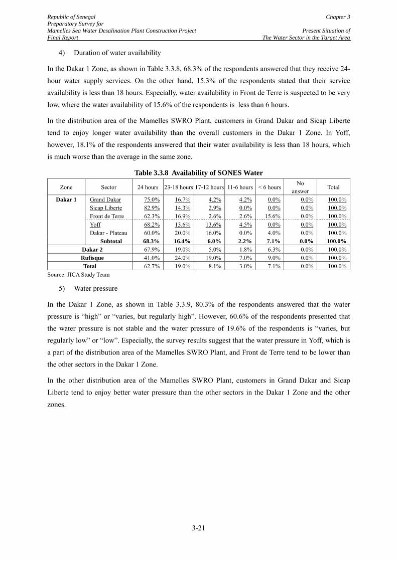
Republic of Senegal Chapter 3 Preparatory Survey for Mamelles Sea Water Desalination Plant Construction Project Present Situation of Final Report The Water Sector in the Target Area
4) Duration of water availability
In the Dakar 1 Zone, as shown in Table 3.3.8, 68.3% of the respondents answered that they receive 24-hour water supply services. On the other hand, 15.3% of the respondents stated that their service availability is less than 18 hours. Especially, water availability in Front de Terre is suspected to be very low, where the water availability of 15.6% of the respondents is less than 6 hours.
In the distribution area of the Mamelles SWRO Plant, customers in Grand Dakar and Sicap Liberte tend to enjoy longer water availability than the overall customers in the Dakar 1 Zone. In Yoff, however, 18.1% of the respondents answered that their water availability is less than 18 hours, which is much worse than the average in the same zone.
Table 3.3.8 Availability of SONES Water
Zone Sector 24 hours 23-18 hours 17-12 hours 11-6 hours < 6 hours No
answer Total
Dakar 1 Grand Dakar 75.0% 16.7% 4.2% 4.2% 0.0% 0.0% 100.0% Sicap Liberte 82.9% 14.3% 2.9% 0.0% 0.0% 0.0% 100.0% Front de Terre 62.3% 16.9% 2.6% 2.6% 15.6% 0.0% 100.0% Yoff 68.2% 13.6% 13.6% 4.5% 0.0% 0.0% 100.0% Dakar - Plateau 60.0% 20.0% 16.0% 0.0% 4.0% 0.0% 100.0%
Subtotal 68.3% 16.4% 6.0% 2.2% 7.1% 0.0% 100.0% Dakar 2 67.9% 19.0% 5.0% 1.8% 6.3% 0.0% 100.0% Rufisque 41.0% 24.0% 19.0% 7.0% 9.0% 0.0% 100.0% Total 62.7% 19.0% 8.1% 3.0% 7.1% 0.0% 100.0%
Source: JICA Study Team
5) Water pressure
In the Dakar 1 Zone, as shown in Table 3.3.9, 80.3% of the respondents answered that the water pressure is “high” or “varies, but regularly high”. However, 60.6% of the respondents presented that the water pressure is not stable and the water pressure of 19.6% of the respondents is “varies, but regularly low” or “low”. Especially, the survey results suggest that the water pressure in Yoff, which is a part of the distribution area of the Mamelles SWRO Plant, and Front de Terre tend to be lower than the other sectors in the Dakar 1 Zone.
In the other distribution area of the Mamelles SWRO Plant, customers in Grand Dakar and Sicap Liberte tend to enjoy better water pressure than the other sectors in the Dakar 1 Zone and the other zones.
3-21
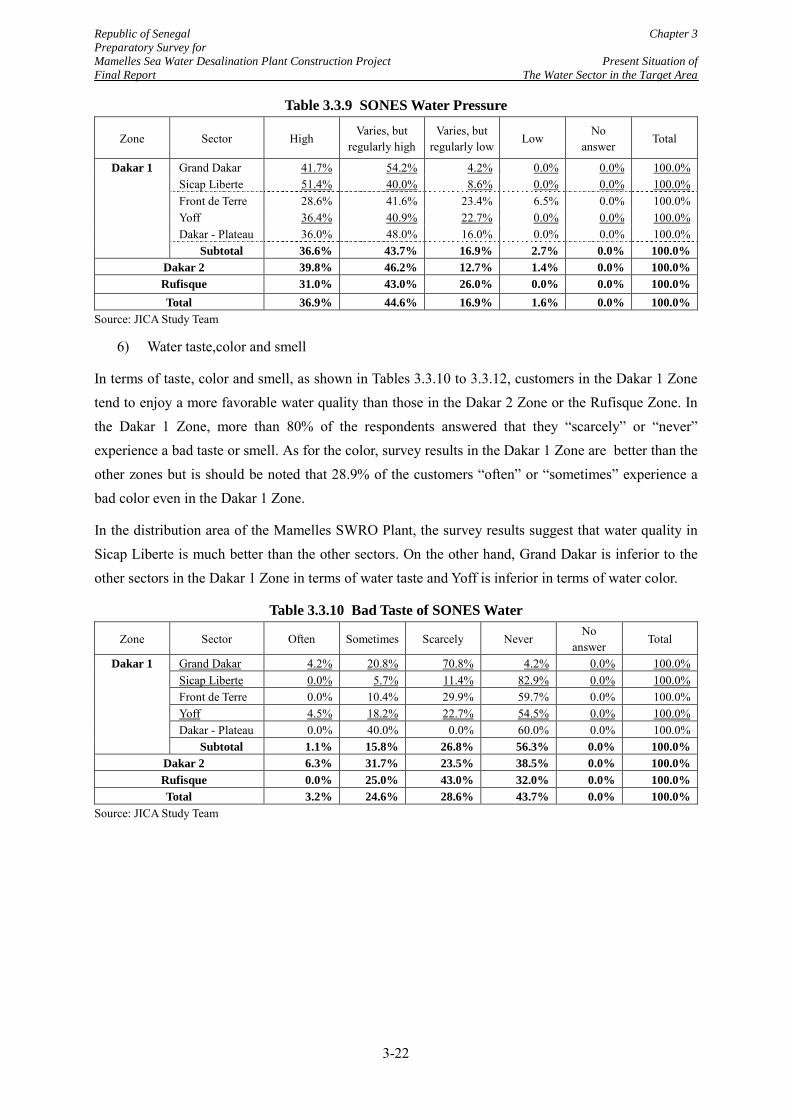
Republic of Senegal Chapter 3 Preparatory Survey for Mamelles Sea Water Desalination Plant Construction Project Present Situation of Final Report The Water Sector in the Target Area
Table 3.3.9 SONES Water Pressure
Zone Sector High Varies, but
regularly high Varies, but
regularly low Low
No answer
Total
Dakar 1 Grand Dakar 41.7% 54.2% 4.2% 0.0% 0.0% 100.0% Sicap Liberte 51.4% 40.0% 8.6% 0.0% 0.0% 100.0% Front de Terre 28.6% 41.6% 23.4% 6.5% 0.0% 100.0% Yoff 36.4% 40.9% 22.7% 0.0% 0.0% 100.0% Dakar - Plateau 36.0% 48.0% 16.0% 0.0% 0.0% 100.0%
Subtotal 36.6% 43.7% 16.9% 2.7% 0.0% 100.0% Dakar 2 39.8% 46.2% 12.7% 1.4% 0.0% 100.0% Rufisque 31.0% 43.0% 26.0% 0.0% 0.0% 100.0% Total 36.9% 44.6% 16.9% 1.6% 0.0% 100.0%
Source: JICA Study Team
6) Water taste,color and smell
In terms of taste, color and smell, as shown in Tables 3.3.10 to 3.3.12, customers in the Dakar 1 Zone tend to enjoy a more favorable water quality than those in the Dakar 2 Zone or the Rufisque Zone. In the Dakar 1 Zone, more than 80% of the respondents answered that they “scarcely” or “never” experience a bad taste or smell. As for the color, survey results in the Dakar 1 Zone are better than the other zones but is should be noted that 28.9% of the customers “often” or “sometimes” experience a bad color even in the Dakar 1 Zone.
In the distribution area of the Mamelles SWRO Plant, the survey results suggest that water quality in Sicap Liberte is much better than the other sectors. On the other hand, Grand Dakar is inferior to the other sectors in the Dakar 1 Zone in terms of water taste and Yoff is inferior in terms of water color.
Table 3.3.10 Bad Taste of SONES Water
Zone Sector Often Sometimes Scarcely Never No
answer Total
Dakar 1 Grand Dakar 4.2% 20.8% 70.8% 4.2% 0.0% 100.0% Sicap Liberte 0.0% 5.7% 11.4% 82.9% 0.0% 100.0% Front de Terre 0.0% 10.4% 29.9% 59.7% 0.0% 100.0% Yoff 4.5% 18.2% 22.7% 54.5% 0.0% 100.0% Dakar - Plateau 0.0% 40.0% 0.0% 60.0% 0.0% 100.0%
Subtotal 1.1% 15.8% 26.8% 56.3% 0.0% 100.0% Dakar 2 6.3% 31.7% 23.5% 38.5% 0.0% 100.0% Rufisque 0.0% 25.0% 43.0% 32.0% 0.0% 100.0% Total 3.2% 24.6% 28.6% 43.7% 0.0% 100.0%
Source: JICA Study Team
3-22
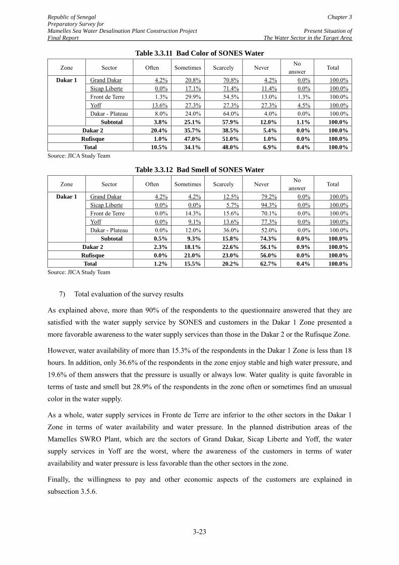
Republic of Senegal Chapter 3 Preparatory Survey for Mamelles Sea Water Desalination Plant Construction Project Present Situation of Final Report The Water Sector in the Target Area
Table 3.3.11 Bad Color of SONES Water
Zone Sector Often Sometimes Scarcely Never No
answer Total
Dakar 1 Grand Dakar 4.2% 20.8% 70.8% 4.2% 0.0% 100.0% Sicap Liberte 0.0% 17.1% 71.4% 11.4% 0.0% 100.0% Front de Terre 1.3% 29.9% 54.5% 13.0% 1.3% 100.0% Yoff 13.6% 27.3% 27.3% 27.3% 4.5% 100.0% Dakar - Plateau 8.0% 24.0% 64.0% 4.0% 0.0% 100.0%
Subtotal 3.8% 25.1% 57.9% 12.0% 1.1% 100.0% Dakar 2 20.4% 35.7% 38.5% 5.4% 0.0% 100.0% Rufisque 1.0% 47.0% 51.0% 1.0% 0.0% 100.0% Total 10.5% 34.1% 48.0% 6.9% 0.4% 100.0%
Source: JICA Study Team
Table 3.3.12 Bad Smell of SONES Water
Zone Sector Often Sometimes Scarcely Never No
answer Total
Dakar 1 Grand Dakar 4.2% 4.2% 12.5% 79.2% 0.0% 100.0% Sicap Liberte 0.0% 0.0% 5.7% 94.3% 0.0% 100.0% Front de Terre 0.0% 14.3% 15.6% 70.1% 0.0% 100.0% Yoff 0.0% 9.1% 13.6% 77.3% 0.0% 100.0% Dakar - Plateau 0.0% 12.0% 36.0% 52.0% 0.0% 100.0%
Subtotal 0.5% 9.3% 15.8% 74.3% 0.0% 100.0% Dakar 2 2.3% 18.1% 22.6% 56.1% 0.9% 100.0% Rufisque 0.0% 21.0% 23.0% 56.0% 0.0% 100.0% Total 1.2% 15.5% 20.2% 62.7% 0.4% 100.0%
Source: JICA Study Team
7) Total evaluation of the survey results
As explained above, more than 90% of the respondents to the questionnaire answered that they are satisfied with the water supply service by SONES and customers in the Dakar 1 Zone presented a more favorable awareness to the water supply services than those in the Dakar 2 or the Rufisque Zone.
However, water availability of more than 15.3% of the respondents in the Dakar 1 Zone is less than 18 hours. In addition, only 36.6% of the respondents in the zone enjoy stable and high water pressure, and 19.6% of them answers that the pressure is usually or always low. Water quality is quite favorable in terms of taste and smell but 28.9% of the respondents in the zone often or sometimes find an unusual color in the water supply.
As a whole, water supply services in Fronte de Terre are inferior to the other sectors in the Dakar 1 Zone in terms of water availability and water pressure. In the planned distribution areas of the Mamelles SWRO Plant, which are the sectors of Grand Dakar, Sicap Liberte and Yoff, the water supply services in Yoff are the worst, where the awareness of the customers in terms of water availability and water pressure is less favorable than the other sectors in the zone.
Finally, the willingness to pay and other economic aspects of the customers are explained in subsection 3.5.6.
3-23
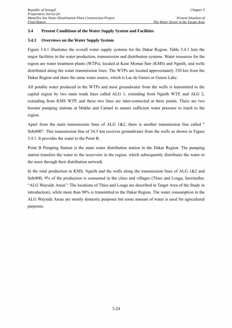
Republic of Senegal Chapter 3 Preparatory Survey for Mamelles Sea Water Desalination Plant Construction Project Present Situation of Final Report The Water Sector in the Target Area
3.4 Present Conditions of the Water Supply System and Facilities
3.4.1 Overviews on the Water Supply System
Figure 3.4.1 illustrates the overall water supply systems for the Dakar Region. Table 3.4.1 lists the major facilities in the water production, transmission and distribution systems. Water resources for the region are water treatment plants (WTPs), located at Keur Momar Sarr (KMS) and Ngnith, and wells distributed along the water transmission lines. The WTPs are located approximately 250 km from the Dakar Region and share the same water source, which is Lac de Guiers or Guiers Lake.
All potable water produced in the WTPs and most groundwater from the wells is transmitted to the capital region by two main trunk lines called ALG 1, extending from Ngnith WTP, and ALG 2, extending from KMS WTP, and these two lines are inter-connected at three points. There are two booster pumping stations at Mekhe and Carmel to ensure sufficient water pressure to reach to the region.
Apart from the main transmission lines of ALG 1&2, there is another transmission line called " Sebi800". This transmission line of 34.5 km receives groundwater from the wells as shown in Figure 3.4.1. It provides the water to the Point B.
Point B Pumping Station is the main water distribution station in the Dakar Region. The pumping station transfers the water to the reservoirs in the region, which subsequently distributes the water to the users through their distribution network.
In the total production in KMS, Ngnith and the wells along the transmission lines of ALG 1&2 and Sebi800, 9% of the production is consumed in the cities and villages (Thies and Louga, hereinafter, “ALG Wayside Areas”: The locations of Thies and Louga are described in Target Area of the Study in introduction), while more than 90% is transmitted to the Dakar Region. The water consumption in the ALG Wayside Areas are mostly domestic purposes but some amount of water is used for agricultural purposes.
3-24
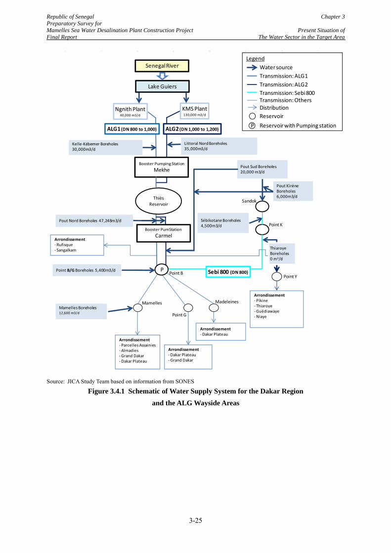
Republic of Senegal Chapter 3 Preparatory Survey for Mamelles Sea Water Desalination Plant Construction Project Present Situation of Final Report The Water Sector in the Target Area
Source: JICA Study Team based on information from SONES
Figure 3.4.1 Schematic of Water Supply System for the Dakar Region and the ALG Wayside Areas
ThièsReservoir
ALG2(DN 1,000 to 1,200)
Kelle-Kébemer Boreholes 30,000m3/d
Littoral Nord Boreholes 35,000m3/d
Ngnith Plant40,000 m3/d
KMS Plant130,000 m3/d
Senegal River
Lake Guiers
ALG1 (DN 800 to 1,000)
Booster Pumping StationMekhe
Arrondissement- Rufisque- Sangalkam
Point B
Pout Nord Boreholes 47,248m3/d
Point B/G Boreholes 5,400m3/d
Madeleines
Arrondissement- Dakar Plateau
Arrondissement- Dakar Plateau- Grand Dakar
Point G
Arrondissement- Parcelles Assainies- Almadies- Grand Dakar- Dakar Plateau
Mamelles Boreholes 12,600 m3/d
Mamelles
Arrondissement- Pikine- Thiaroye- Guédiawaye- Niaye
Point Y
Sébikotane Boreholes4,500m3/d
Pout Kiréne Boreholes 6,000m3/d
Sandok
Point K
Pout Sud Boreholes 20,000 m3/d
Sebi 800 (DN 800)
Booster PumStationCarmel
P
Transmission: Sebi 800
Transmission: ALG1
ReservoirP Reservoir with Pumping station
Distribution
Transmission: ALG2
Water sourceLegend
Transmission: Others
ThiaroyeBoreholes 0 m3/d
3-25
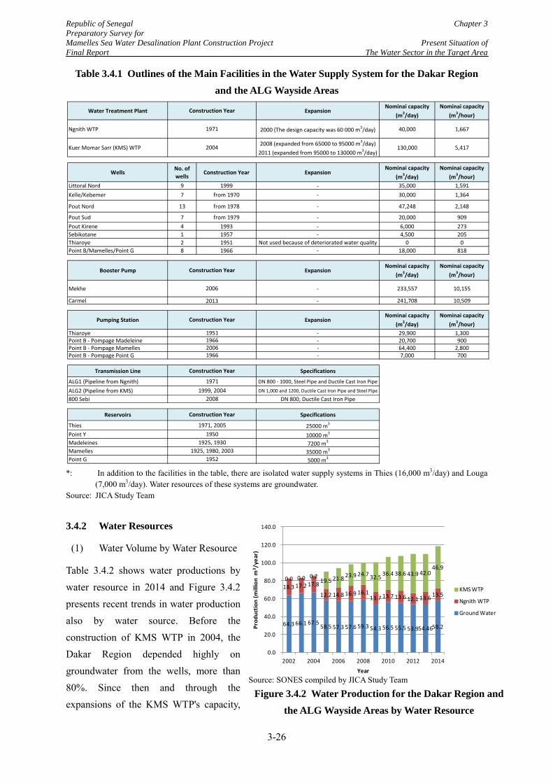
Republic of Senegal Chapter 3 Preparatory Survey for Mamelles Sea Water Desalination Plant Construction Project Present Situation of Final Report The Water Sector in the Target Area
Table 3.4.1 Outlines of the Main Facilities in the Water Supply System for the Dakar Region and the ALG Wayside Areas
*: In addition to the facilities in the table, there are isolated water supply systems in Thies (16,000 m3/day) and Louga
(7,000 m3/day). Water resources of these systems are groundwater. Source: JICA Study Team
3.4.2 Water Resources
(1) Water Volume by Water Resource
Table 3.4.2 shows water productions by water resource in 2014 and Figure 3.4.2 presents recent trends in water production also by water source. Before the construction of KMS WTP in 2004, the Dakar Region depended highly on groundwater from the wells, more than 80%. Since then and through the expansions of the KMS WTP's capacity,
Water Treatment Plant ExpansionNominai capacity
(m3/day)Nominai capacity
(m3/hour)
Ngnith WTP 2000 (The design capacity was 60 000 m3/day) 40,000 1,667
Kuer Momar Sarr (KMS) WTP2008 (expanded from 65000 to 95000 m3/day)
2011 (expanded from 95000 to 130000 m3/day)130,000 5,417
WellsNo. ofwells
Construction Year ExpansionNominai capacity
(m3/day)Nominai capacity
(m3/hour)Littoral Nord 9 1999 - 35,000 1,591Kelle/Kebemer 7 from 1970 - 30,000 1,364
Pout Nord 13 from 1978 - 47,248 2,148
Pout Sud 7 from 1979 - 20,000 909Pout Kirene 4 1993 - 6,000 273Sebikotane 1 1957 - 4,500 205Thiaroye 2 1951 Not used because of deteriorated water quality 0 0Point B/Mamelles/Point G 8 1966 - 18,000 818
Booster Pump ExpansionNominai capacity
(m3/day)Nominai capacity
(m3/hour)
Mekhe - 233,557 10,155
Carmel - 241,708 10,509
Pumping Station ExpansionNominai capacity
(m3/day)Nominai capacity
(m3/hour)Thiaroye - 29,900 1,300Point B - Pompage Madeleine - 20,700 900Point B - Pompage Mamelles - 64,400 2,800Point B - Pompage Point G - 7,000 700
Transmission Line Specifications
ALG1 (Pipeline from Ngnith) DN 800 - 1000, Steel Pipe and Ductile Cast Iron Pipe
ALG2 (Pipeline from KMS) DN 1,000 and 1200, Ductile Cast Iron Pipe and Steel Pipe
800 Sebi DN 800, Ductile Cast Iron Pipe
Reservoirs Specifications
Thies 25000 m3
Point Y 10000 m3
Madeleines 7200 m3
Mamelles 35000 m3
Point G 5000 m3
1925, 19301925, 1980, 2003
1952
Construction Year
1971, 20051950
19711999, 2004
2008
Construction Year
1951196620061966
Construction Year
1971
2004
Construction Year
2006
2013
Construction Year
Source: SONES compiled by JICA Study Team
Figure 3.4.2 Water Production for the Dakar Region and the ALG Wayside Areas by Water Resource
64.3 66.1 67.5 58.5 57.3 57.6 59.3 54.3 56.5 55.5 53.9 54.4658.2
18.3 17.2 17.8
12.2 14.8 16.9 16.1 13.7 13.7 13.6 12.1 13.6 13.5
0.0 0.0 0.2 19.5 21.8 23.9 24.7 32.5 36.4 38.6 43.9 42.0
46.9
0.0
20.0
40.0
60.0
80.0
100.0
120.0
140.0
2002 2004 2006 2008 2010 2012 2014
Prod
uctio
n (m
illio
n m
3 /ye
ar)
Year
KMS WTP
Ngnith WTP
Ground Water
3-26
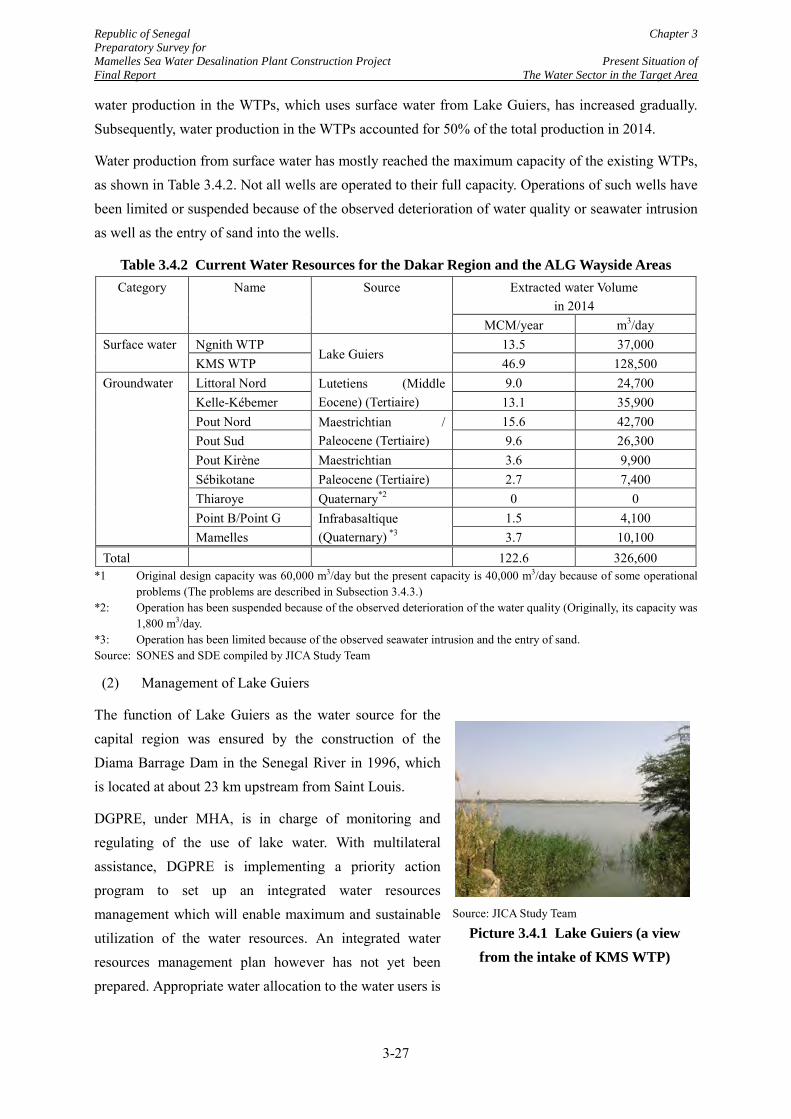
Republic of Senegal Chapter 3 Preparatory Survey for Mamelles Sea Water Desalination Plant Construction Project Present Situation of Final Report The Water Sector in the Target Area
water production in the WTPs, which uses surface water from Lake Guiers, has increased gradually. Subsequently, water production in the WTPs accounted for 50% of the total production in 2014.
Water production from surface water has mostly reached the maximum capacity of the existing WTPs, as shown in Table 3.4.2. Not all wells are operated to their full capacity. Operations of such wells have been limited or suspended because of the observed deterioration of water quality or seawater intrusion as well as the entry of sand into the wells.
Table 3.4.2 Current Water Resources for the Dakar Region and the ALG Wayside Areas Category Name Source Extracted water Volume
in 2014 MCM/year m3/day
Surface water Ngnith WTP Lake Guiers
13.5 37,000 KMS WTP 46.9 128,500
Groundwater
Littoral Nord Lutetiens (Middle Eocene) (Tertiaire)
9.0 24,700 Kelle-Kébemer 13.1 35,900 Pout Nord Maestrichtian /
Paleocene (Tertiaire) 15.6 42,700
Pout Sud 9.6 26,300 Pout Kirène Maestrichtian 3.6 9,900 Sébikotane Paleocene (Tertiaire) 2.7 7,400 Thiaroye Quaternary*2 0 0 Point B/Point G Infrabasaltique
(Quaternary) *3 1.5 4,100
Mamelles 3.7 10,100 Total 122.6 326,600
*1 Original design capacity was 60,000 m3/day but the present capacity is 40,000 m3/day because of some operational problems (The problems are described in Subsection 3.4.3.)
*2: Operation has been suspended because of the observed deterioration of the water quality (Originally, its capacity was 1,800 m3/day.
*3: Operation has been limited because of the observed seawater intrusion and the entry of sand. Source: SONES and SDE compiled by JICA Study Team
(2) Management of Lake Guiers
The function of Lake Guiers as the water source for the capital region was ensured by the construction of the Diama Barrage Dam in the Senegal River in 1996, which is located at about 23 km upstream from Saint Louis.
DGPRE, under MHA, is in charge of monitoring and regulating of the use of lake water. With multilateral assistance, DGPRE is implementing a priority action program to set up an integrated water resources management which will enable maximum and sustainable utilization of the water resources. An integrated water resources management plan however has not yet been prepared. Appropriate water allocation to the water users is
Source: JICA Study Team
Picture 3.4.1 Lake Guiers (a view from the intake of KMS WTP)
3-27
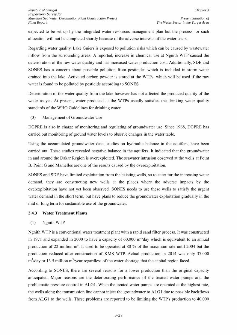
Republic of Senegal Chapter 3 Preparatory Survey for Mamelles Sea Water Desalination Plant Construction Project Present Situation of Final Report The Water Sector in the Target Area
expected to be set up by the integrated water resources management plan but the process for such allocation will not be completed shortly because of the adverse interests of the water users.
Regarding water quality, Lake Guiers is exposed to pollution risks which can be caused by wastewater inflow from the surrounding areas. A reported, increase in chemical use at Ngnith WTP caused the deterioration of the raw water quality and has increased water production cost. Additionally, SDE and SONES has a concern about possible pollution from pesticides which is included in storm water drained into the lake. Activated carbon powder is stored at the WTPs, which will be used if the raw water is found to be polluted by pesticide according to SONES.
Deterioration of the water quality from the lake however has not affected the produced quality of the water as yet. At present, water produced at the WTPs usually satisfies the drinking water quality standards of the WHO Guidelines for drinking water.
(3) Management of Groundwater Use
DGPRE is also in charge of monitoring and regulating of groundwater use. Since 1968, DGPRE has carried out monitoring of ground water levels to observe changes in the water table.
Using the accumulated groundwater data, studies on hydraulic balance in the aquifers, have been carried out. These studies revealed negative balance in the aquifers. It indicated that the groundwater in and around the Dakar Region is overexploited. The seawater intrusion observed at the wells at Point B, Point G and Mamelles are one of the results caused by the overexploitation.
SONES and SDE have limited exploitation from the existing wells, so to cater for the increasing water demand, they are constructing new wells at the places where the adverse impacts by the overexploitation have not yet been observed. SONES needs to use these wells to satisfy the urgent water demand in the short term, but have plans to reduce the groundwater exploitation gradually in the mid or long term for sustainable use of the groundwater.
3.4.3 Water Treatment Plants
(1) Ngnith WTP
Ngnith WTP is a conventional water treatment plant with a rapid sand filter process. It was constructed in 1971 and expanded in 2000 to have a capacity of 60,000 m3/day which is equivalent to an annual production of 22 million m3. It used to be operated at 80 % of the maximum rate until 2004 but the production reduced after construction of KMS WTP. Actual production in 2014 was only 37,000 m3/day or 13.5 million m3/year regardless of the water shortage that the capital region faced.
According to SONES, there are several reasons for a lower production than the original capacity anticipated. Major reasons are the deteriorating performance of the treated water pumps and the problematic pressure control in ALG1. When the treated water pumps are operated at the highest rate, the wells along the transmission line cannot inject the groundwater to ALG1 due to possible backflows from ALG1 to the wells. These problems are reported to be limiting the WTP's production to 40,000
3-28
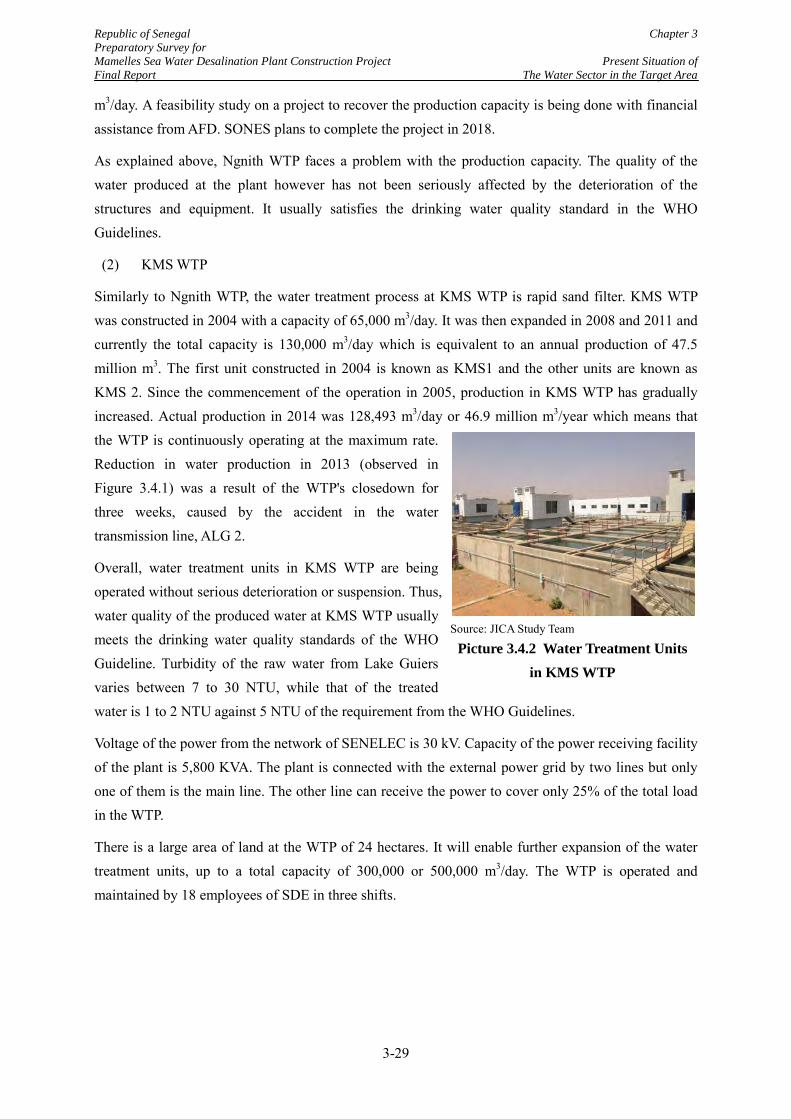
Republic of Senegal Chapter 3 Preparatory Survey for Mamelles Sea Water Desalination Plant Construction Project Present Situation of Final Report The Water Sector in the Target Area
m3/day. A feasibility study on a project to recover the production capacity is being done with financial assistance from AFD. SONES plans to complete the project in 2018.
As explained above, Ngnith WTP faces a problem with the production capacity. The quality of the water produced at the plant however has not been seriously affected by the deterioration of the structures and equipment. It usually satisfies the drinking water quality standard in the WHO Guidelines.
(2) KMS WTP
Similarly to Ngnith WTP, the water treatment process at KMS WTP is rapid sand filter. KMS WTP was constructed in 2004 with a capacity of 65,000 m3/day. It was then expanded in 2008 and 2011 and currently the total capacity is 130,000 m3/day which is equivalent to an annual production of 47.5 million m3. The first unit constructed in 2004 is known as KMS1 and the other units are known as KMS 2. Since the commencement of the operation in 2005, production in KMS WTP has gradually increased. Actual production in 2014 was 128,493 m3/day or 46.9 million m3/year which means that the WTP is continuously operating at the maximum rate. Reduction in water production in 2013 (observed in Figure 3.4.1) was a result of the WTP's closedown for three weeks, caused by the accident in the water transmission line, ALG 2.
Overall, water treatment units in KMS WTP are being operated without serious deterioration or suspension. Thus, water quality of the produced water at KMS WTP usually meets the drinking water quality standards of the WHO Guideline. Turbidity of the raw water from Lake Guiers varies between 7 to 30 NTU, while that of the treated water is 1 to 2 NTU against 5 NTU of the requirement from the WHO Guidelines.
Voltage of the power from the network of SENELEC is 30 kV. Capacity of the power receiving facility of the plant is 5,800 KVA. The plant is connected with the external power grid by two lines but only one of them is the main line. The other line can receive the power to cover only 25% of the total load in the WTP.
There is a large area of land at the WTP of 24 hectares. It will enable further expansion of the water treatment units, up to a total capacity of 300,000 or 500,000 m3/day. The WTP is operated and maintained by 18 employees of SDE in three shifts.
Source: JICA Study Team
Picture 3.4.2 Water Treatment Units in KMS WTP
3-29
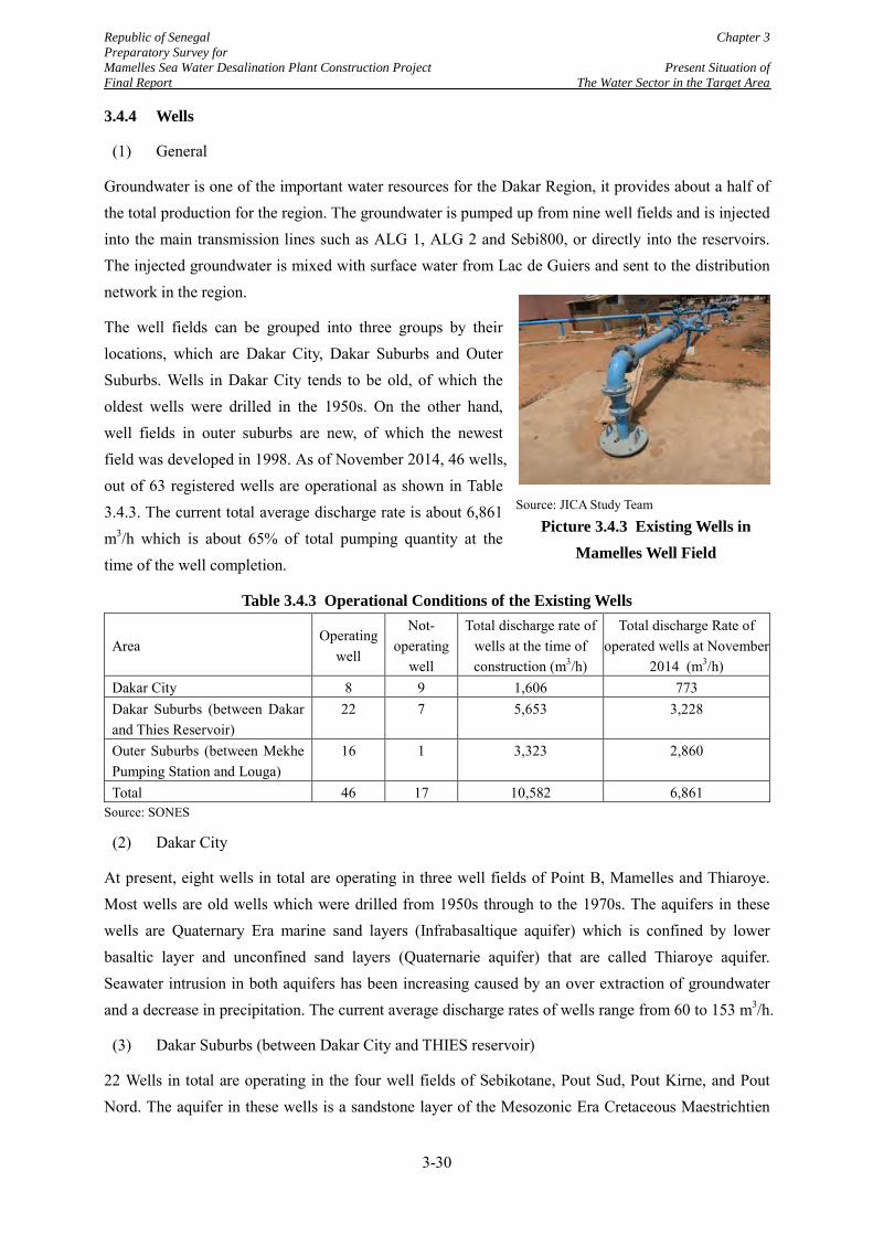
Republic of Senegal Chapter 3 Preparatory Survey for Mamelles Sea Water Desalination Plant Construction Project Present Situation of Final Report The Water Sector in the Target Area
3.4.4 Wells
(1) General
Groundwater is one of the important water resources for the Dakar Region, it provides about a half of the total production for the region. The groundwater is pumped up from nine well fields and is injected into the main transmission lines such as ALG 1, ALG 2 and Sebi800, or directly into the reservoirs. The injected groundwater is mixed with surface water from Lac de Guiers and sent to the distribution network in the region.
The well fields can be grouped into three groups by their locations, which are Dakar City, Dakar Suburbs and Outer Suburbs. Wells in Dakar City tends to be old, of which the oldest wells were drilled in the 1950s. On the other hand, well fields in outer suburbs are new, of which the newest field was developed in 1998. As of November 2014, 46 wells, out of 63 registered wells are operational as shown in Table 3.4.3. The current total average discharge rate is about 6,861 m3/h which is about 65% of total pumping quantity at the time of the well completion.
Table 3.4.3 Operational Conditions of the Existing Wells
Area Operating
well
Not-operating
well
Total discharge rate of wells at the time of construction (m3/h)
Total discharge Rate of operated wells at November
2014 (m3/h) Dakar City 8 9 1,606 773 Dakar Suburbs (between Dakar and Thies Reservoir)
22 7 5,653 3,228
Outer Suburbs (between Mekhe Pumping Station and Louga)
16 1 3,323 2,860
Total 46 17 10,582 6,861 Source: SONES
(2) Dakar City
At present, eight wells in total are operating in three well fields of Point B, Mamelles and Thiaroye. Most wells are old wells which were drilled from 1950s through to the 1970s. The aquifers in these wells are Quaternary Era marine sand layers (Infrabasaltique aquifer) which is confined by lower basaltic layer and unconfined sand layers (Quaternarie aquifer) that are called Thiaroye aquifer. Seawater intrusion in both aquifers has been increasing caused by an over extraction of groundwater and a decrease in precipitation. The current average discharge rates of wells range from 60 to 153 m3/h.
(3) Dakar Suburbs (between Dakar City and THIES reservoir)
22 Wells in total are operating in the four well fields of Sebikotane, Pout Sud, Pout Kirne, and Pout Nord. The aquifer in these wells is a sandstone layer of the Mesozonic Era Cretaceous Maestrichtien
Source: JICA Study Team
Picture 3.4.3 Existing Wells in Mamelles Well Field
3-30
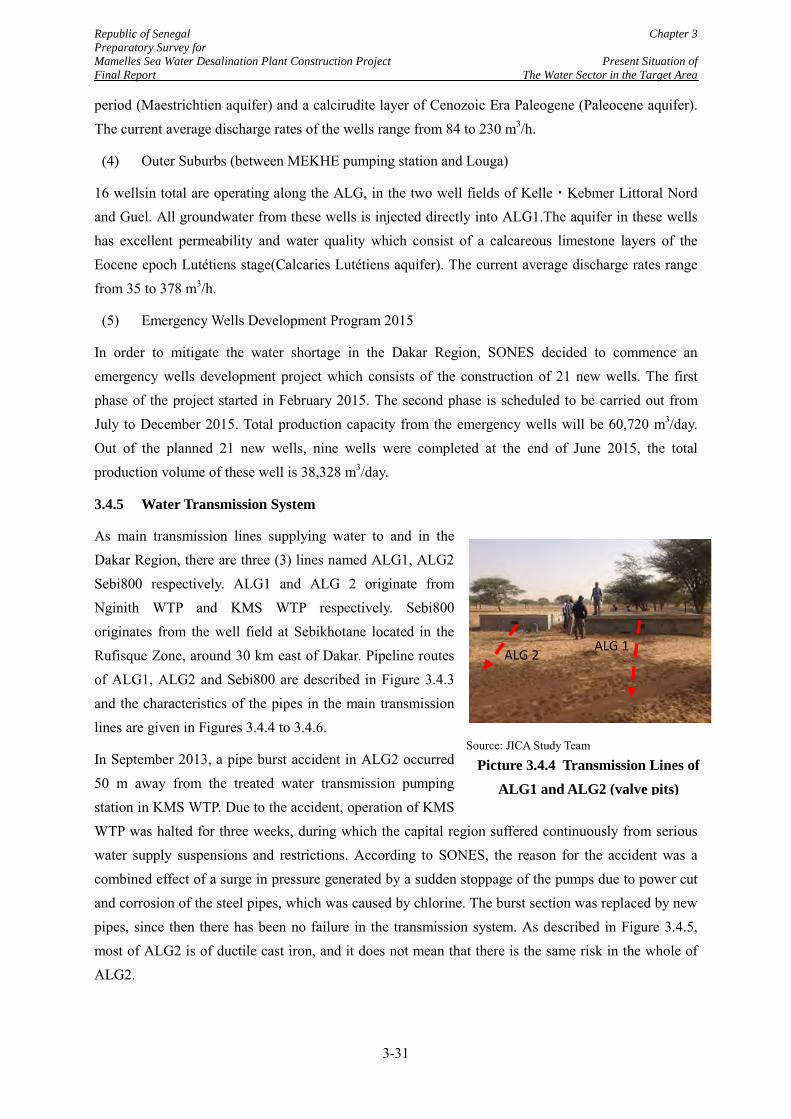
Republic of Senegal Chapter 3 Preparatory Survey for Mamelles Sea Water Desalination Plant Construction Project Present Situation of Final Report The Water Sector in the Target Area
period (Maestrichtien aquifer) and a calcirudite layer of Cenozoic Era Paleogene (Paleocene aquifer). The current average discharge rates of the wells range from 84 to 230 m3/h.
(4) Outer Suburbs (between MEKHE pumping station and Louga)
16 wellsin total are operating along the ALG, in the two well fields of Kelle・Kebmer Littoral Nord and Guel. All groundwater from these wells is injected directly into ALG1.The aquifer in these wells has excellent permeability and water quality which consist of a calcareous limestone layers of the Eocene epoch Lutétiens stage(Calcaries Lutétiens aquifer). The current average discharge rates range from 35 to 378 m3/h.
(5) Emergency Wells Development Program 2015
In order to mitigate the water shortage in the Dakar Region, SONES decided to commence an emergency wells development project which consists of the construction of 21 new wells. The first phase of the project started in February 2015. The second phase is scheduled to be carried out from July to December 2015. Total production capacity from the emergency wells will be 60,720 m3/day. Out of the planned 21 new wells, nine wells were completed at the end of June 2015, the total production volume of these well is 38,328 m3/day.
3.4.5 Water Transmission System
As main transmission lines supplying water to and in the Dakar Region, there are three (3) lines named ALG1, ALG2 Sebi800 respectively. ALG1 and ALG 2 originate from Nginith WTP and KMS WTP respectively. Sebi800 originates from the well field at Sebikhotane located in the Rufisque Zone, around 30 km east of Dakar. Pipeline routes of ALG1, ALG2 and Sebi800 are described in Figure 3.4.3 and the characteristics of the pipes in the main transmission lines are given in Figures 3.4.4 to 3.4.6.
In September 2013, a pipe burst accident in ALG2 occurred 50 m away from the treated water transmission pumping station in KMS WTP. Due to the accident, operation of KMS WTP was halted for three weeks, during which the capital region suffered continuously from serious water supply suspensions and restrictions. According to SONES, the reason for the accident was a combined effect of a surge in pressure generated by a sudden stoppage of the pumps due to power cut and corrosion of the steel pipes, which was caused by chlorine. The burst section was replaced by new pipes, since then there has been no failure in the transmission system. As described in Figure 3.4.5, most of ALG2 is of ductile cast iron, and it does not mean that there is the same risk in the whole of ALG2.
Source: JICA Study Team
Picture 3.4.4 Transmission Lines of ALG1 and ALG2 (valve pits)
ALG 2 ALG 1
3-31
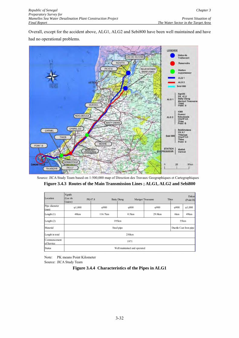
Republic of Senegal Chapter 3 Preparatory Survey for Mamelles Sea Water Desalination Plant Construction Project Present Situation of Final Report The Water Sector in the Target Area
Overall, except for the accident above, ALG1, ALG2 and Sebi800 have been well maintained and have had no operational problems.
Source: JICA Study Team based on 1:500,000 map of Direction des Travaux Geographiques et Cartegraphiques
Figure 3.4.3 Routes of the Main Transmission Lines ; ALG1, ALG2 and Sebi800
Note: PK means Point Kilometer Source: JICA Study Team
Figure 3.4.4 Characteristics of the Pipes in ALG1
Pipe diameter(mm)
φ900 φ1,000
Length (1) 6km 49km
Length (2)
Material
Length in total
Commencementof Service
Status
Location Marigot Tivaouane
48km 116.7km
φ1,000 φ900
Well maintained and operated
PK47.8
250km
1971
55km
Ngnith(Lac deGuiere)
Ductile Cast Iron pipeSteel pipe
Baity DiengDakar
(Point B)
φ800
0.5km
Thies
φ900
29.8km
195km
3-32
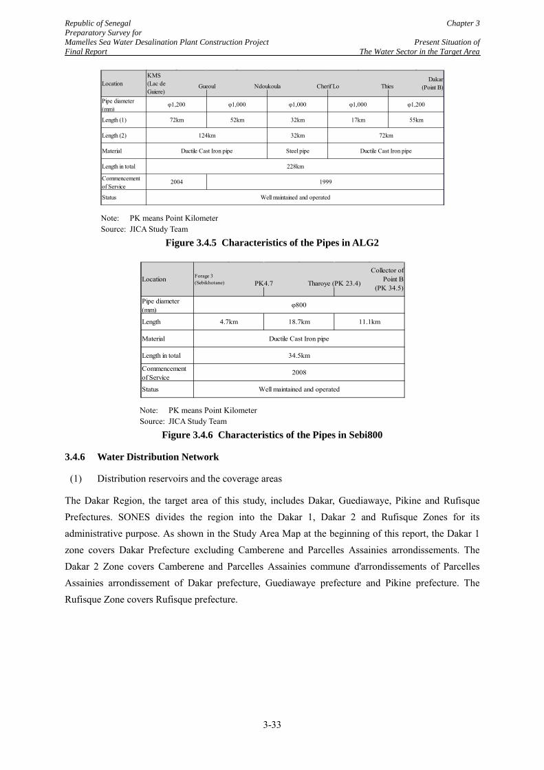
Republic of Senegal Chapter 3 Preparatory Survey for Mamelles Sea Water Desalination Plant Construction Project Present Situation of Final Report The Water Sector in the Target Area
Note: PK means Point Kilometer Source: JICA Study Team
Figure 3.4.5 Characteristics of the Pipes in ALG2
Note: PK means Point Kilometer Source: JICA Study Team
Figure 3.4.6 Characteristics of the Pipes in Sebi800
3.4.6 Water Distribution Network
(1) Distribution reservoirs and the coverage areas
The Dakar Region, the target area of this study, includes Dakar, Guediawaye, Pikine and Rufisque Prefectures. SONES divides the region into the Dakar 1, Dakar 2 and Rufisque Zones for its administrative purpose. As shown in the Study Area Map at the beginning of this report, the Dakar 1 zone covers Dakar Prefecture excluding Camberene and Parcelles Assainies arrondissements. The Dakar 2 Zone covers Camberene and Parcelles Assainies commune d'arrondissements of Parcelles Assainies arrondissement of Dakar prefecture, Guediawaye prefecture and Pikine prefecture. The Rufisque Zone covers Rufisque prefecture.
Pipe diameter(mm)
Length (1)
Length (2)
Material
Length in total
Commencementof Service
Status
17km
ThiesGueoul Ndoukoula Cherif Lo
228km
124km 32km
55km
φ1,200
Location
φ1,200
72km
φ1,000
52km
φ1,000
32km
Well maintained and operated
72km
Ductile Cast Iron pipe Steel pipe Ductile Cast Iron pipe
2004 1999
KMS(Lac deGuiere)
φ1,000
Dakar(Point B)
Pipe diameter(mm)
Length
Material
Length in total
Commencementof Service
Status
Forage 3(Sebikhotane)
2008
Location Tharoye (PK 23.4)PK4.7
φ800
Ductile Cast Iron pipe
34.5km
4.7km 18.7km 11.1km
Collector ofPoint B
(PK 34.5)
Well maintained and operated
3-33
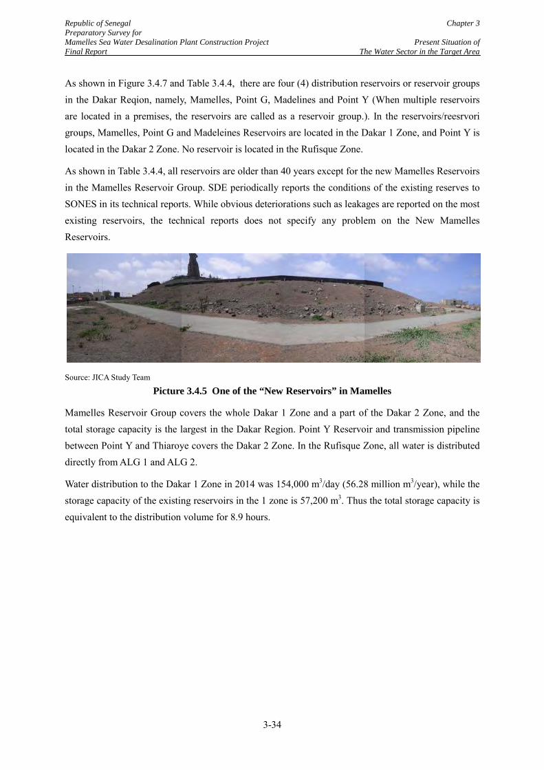
Republic of Senegal Chapter 3 Preparatory Survey for Mamelles Sea Water Desalination Plant Construction Project Present Situation of Final Report The Water Sector in the Target Area
As shown in Figure 3.4.7 and Table 3.4.4, there are four (4) distribution reservoirs or reservoir groups in the Dakar Reqion, namely, Mamelles, Point G, Madelines and Point Y (When multiple reservoirs are located in a premises, the reservoirs are called as a reservoir group.). In the reservoirs/reesrvori groups, Mamelles, Point G and Madeleines Reservoirs are located in the Dakar 1 Zone, and Point Y is located in the Dakar 2 Zone. No reservoir is located in the Rufisque Zone.
As shown in Table 3.4.4, all reservoirs are older than 40 years except for the new Mamelles Reservoirs in the Mamelles Reservoir Group. SDE periodically reports the conditions of the existing reserves to SONES in its technical reports. While obvious deteriorations such as leakages are reported on the most existing reservoirs, the technical reports does not specify any problem on the New Mamelles Reservoirs.
Source: JICA Study Team
Picture 3.4.5 One of the “New Reservoirs” in Mamelles
Mamelles Reservoir Group covers the whole Dakar 1 Zone and a part of the Dakar 2 Zone, and the total storage capacity is the largest in the Dakar Region. Point Y Reservoir and transmission pipeline between Point Y and Thiaroye covers the Dakar 2 Zone. In the Rufisque Zone, all water is distributed directly from ALG 1 and ALG 2.
Water distribution to the Dakar 1 Zone in 2014 was 154,000 m3/day (56.28 million m3/year), while the storage capacity of the existing reservoirs in the 1 zone is 57,200 m3. Thus the total storage capacity is equivalent to the distribution volume for 8.9 hours.
3-34
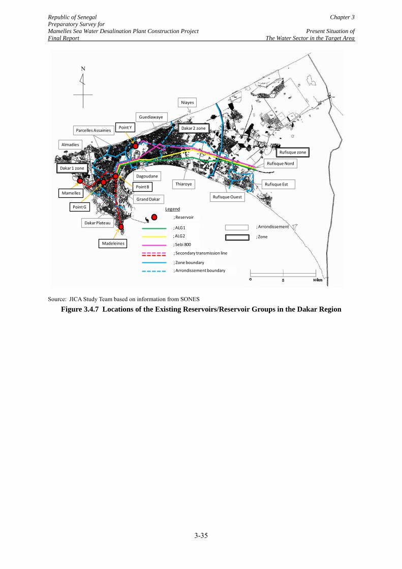
Republic of Senegal Chapter 3 Preparatory Survey for Mamelles Sea Water Desalination Plant Construction Project Present Situation of Final Report The Water Sector in the Target Area
Source: JICA Study Team based on information from SONES
Figure 3.4.7 Locations of the Existing Reservoirs/Reservoir Groups in the Dakar Region
Dakar 1 zone
Dakar 2 zone
Rufisque zone
Legend
; Reservoir
; ALG2
; ALG1
; Sebi 800
; Secondary transmission line
; Zone boundary
; Arrondissement boundary
; Arrondissement
; Zone
Almadies
Dakar Plateau
Grand Dakar
Parcelles Assainies
Dagoudane
Thiaroye
Rufisque Ouest
Niayes
Guediawaye
Mamelles
Point G
Madeleines
Point B
Point Y
Rufisque Est
Rufisque Nord
N
3-35
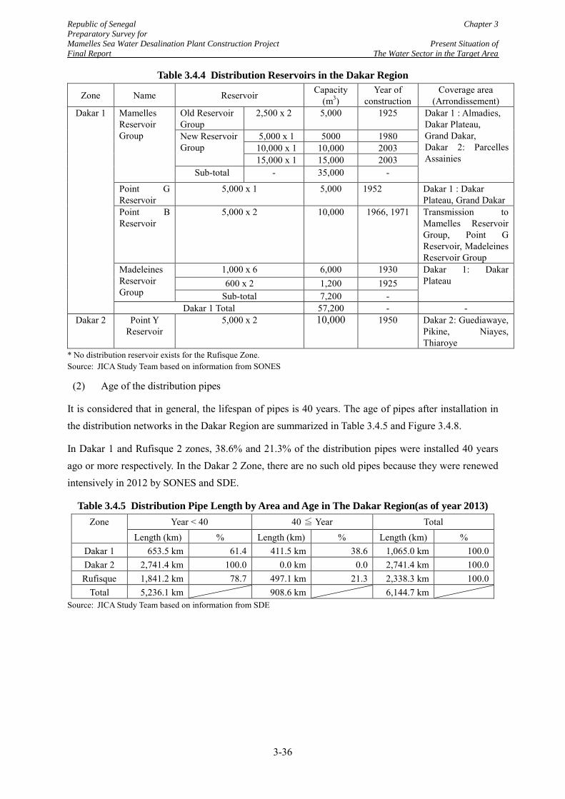
Republic of Senegal Chapter 3 Preparatory Survey for Mamelles Sea Water Desalination Plant Construction Project Present Situation of Final Report The Water Sector in the Target Area
Table 3.4.4 Distribution Reservoirs in the Dakar Region
Zone Name Reservoir Capacity (m3)
Year of construction
Coverage area (Arrondissement)
Dakar 1
Mamelles Reservoir Group
Old Reservoir Group
2,500 x 2 5,000 1925 Dakar 1 : Almadies, Dakar Plateau, Grand Dakar, Dakar 2: Parcelles Assainies
New Reservoir Group
5,000 x 1 5000 1980 10,000 x 1 10,000 2003 15,000 x 1 15,000 2003
Sub-total - 35,000 -
Point G Reservoir
5,000 x 1 5,000 1952 Dakar 1 : Dakar Plateau, Grand Dakar
Point B Reservoir
5,000 x 2 10,000 1966, 1971 Transmission to Mamelles Reservoir Group, Point G Reservoir, Madeleines Reservoir Group
Madeleines Reservoir Group
1,000 x 6 6,000 1930 Dakar 1: Dakar Plateau 600 x 2 1,200 1925
Sub-total 7,200 - Dakar 1 Total 57,200 - -
Dakar 2 Point Y Reservoir
5,000 x 2 10,000 1950 Dakar 2: Guediawaye, Pikine, Niayes, Thiaroye
* No distribution reservoir exists for the Rufisque Zone. Source: JICA Study Team based on information from SONES
(2) Age of the distribution pipes
It is considered that in general, the lifespan of pipes is 40 years. The age of pipes after installation in the distribution networks in the Dakar Region are summarized in Table 3.4.5 and Figure 3.4.8.
In Dakar 1 and Rufisque 2 zones, 38.6% and 21.3% of the distribution pipes were installed 40 years ago or more respectively. In the Dakar 2 Zone, there are no such old pipes because they were renewed intensively in 2012 by SONES and SDE.
Table 3.4.5 Distribution Pipe Length by Area and Age in The Dakar Region(as of year 2013) Zone Year < 40 40 ≦ Year Total
Length (km) % Length (km) % Length (km) % Dakar 1 653.5 km 61.4 411.5 km 38.6 1,065.0 km 100.0 Dakar 2 2,741.4 km 100.0 0.0 km 0.0 2,741.4 km 100.0 Rufisque 1,841.2 km 78.7 497.1 km 21.3 2,338.3 km 100.0
Total 5,236.1 km 908.6 km 6,144.7 km Source: JICA Study Team based on information from SDE
3-36
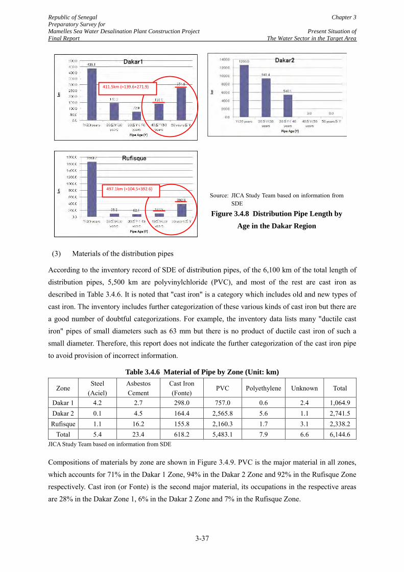
Republic of Senegal Chapter 3 Preparatory Survey for Mamelles Sea Water Desalination Plant Construction Project Present Situation of Final Report The Water Sector in the Target Area
(3) Materials of the distribution pipes
According to the inventory record of SDE of distribution pipes, of the 6,100 km of the total length of distribution pipes, 5,500 km are polyvinylchloride (PVC), and most of the rest are cast iron as described in Table 3.4.6. It is noted that "cast iron" is a category which includes old and new types of cast iron. The inventory includes further categorization of these various kinds of cast iron but there are a good number of doubtful categorizations. For example, the inventory data lists many "ductile cast iron" pipes of small diameters such as 63 mm but there is no product of ductile cast iron of such a small diameter. Therefore, this report does not indicate the further categorization of the cast iron pipe to avoid provision of incorrect information.
Table 3.4.6 Material of Pipe by Zone (Unit: km)
Zone Steel
(Aciel) Asbestos Cement
Cast Iron (Fonte)
PVC Polyethylene Unknown Total
Dakar 1 4.2 2.7 298.0 757.0 0.6 2.4 1,064.9 Dakar 2 0.1 4.5 164.4 2,565.8 5.6 1.1 2,741.5 Rufisque 1.1 16.2 155.8 2,160.3 1.7 3.1 2,338.2
Total 5.4 23.4 618.2 5,483.1 7.9 6.6 6,144.6 JICA Study Team based on information from SDE
Compositions of materials by zone are shown in Figure 3.4.9. PVC is the major material in all zones, which accounts for 71% in the Dakar 1 Zone, 94% in the Dakar 2 Zone and 92% in the Rufisque Zone respectively. Cast iron (or Fonte) is the second major material, its occupations in the respective areas are 28% in the Dakar Zone 1, 6% in the Dakar 2 Zone and 7% in the Rufisque Zone.
411.5km (=139.6+271.9)
497.1km (=104.5+392.6)
Source: JICA Study Team based on information from SDE
Figure 3.4.8 Distribution Pipe Length by Age in the Dakar Region
3-37
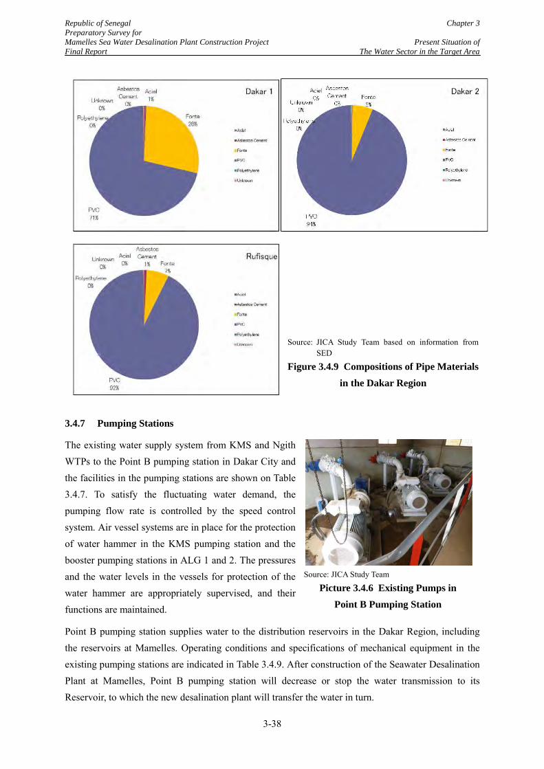
Republic of Senegal Chapter 3 Preparatory Survey for Mamelles Sea Water Desalination Plant Construction Project Present Situation of Final Report The Water Sector in the Target Area
3.4.7 Pumping Stations
The existing water supply system from KMS and Ngith WTPs to the Point B pumping station in Dakar City and the facilities in the pumping stations are shown on Table 3.4.7. To satisfy the fluctuating water demand, the pumping flow rate is controlled by the speed control system. Air vessel systems are in place for the protection of water hammer in the KMS pumping station and the booster pumping stations in ALG 1 and 2. The pressures and the water levels in the vessels for protection of the water hammer are appropriately supervised, and their functions are maintained.
Point B pumping station supplies water to the distribution reservoirs in the Dakar Region, including the reservoirs at Mamelles. Operating conditions and specifications of mechanical equipment in the existing pumping stations are indicated in Table 3.4.9. After construction of the Seawater Desalination Plant at Mamelles, Point B pumping station will decrease or stop the water transmission to its Reservoir, to which the new desalination plant will transfer the water in turn.
Source: JICA Study Team based on information from SED
Figure 3.4.9 Compositions of Pipe Materials in the Dakar Region
Source: JICA Study Team
Picture 3.4.6 Existing Pumps in Point B Pumping Station
3-38
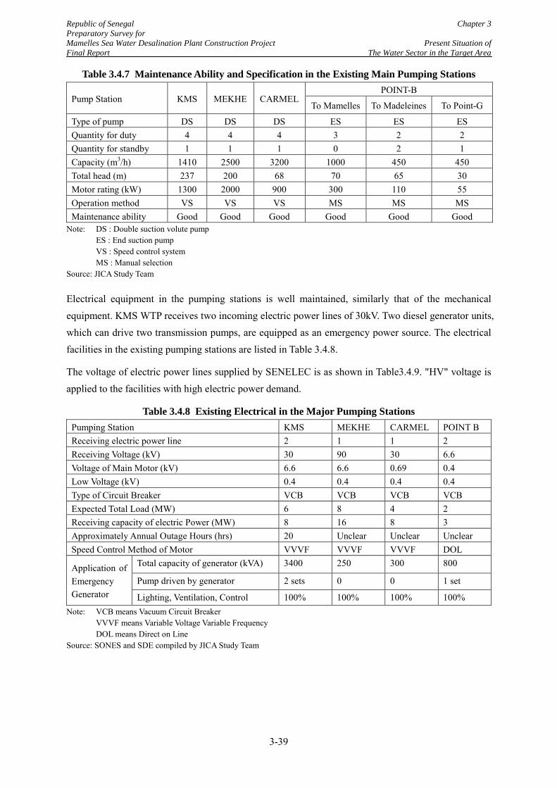
Republic of Senegal Chapter 3 Preparatory Survey for Mamelles Sea Water Desalination Plant Construction Project Present Situation of Final Report The Water Sector in the Target Area
Table 3.4.7 Maintenance Ability and Specification in the Existing Main Pumping Stations
Pump Station KMS MEKHE CARMEL POINT-B
To Mamelles To Madeleines To Point-G
Type of pump DS DS DS ES ES ES Quantity for duty 4 4 4 3 2 2 Quantity for standby 1 1 1 0 2 1 Capacity (m3/h) 1410 2500 3200 1000 450 450 Total head (m) 237 200 68 70 65 30 Motor rating (kW) 1300 2000 900 300 110 55 Operation method VS VS VS MS MS MS Maintenance ability Good Good Good Good Good Good
Note: DS : Double suction volute pump ES : End suction pump VS : Speed control system MS : Manual selection Source: JICA Study Team
Electrical equipment in the pumping stations is well maintained, similarly that of the mechanical equipment. KMS WTP receives two incoming electric power lines of 30kV. Two diesel generator units, which can drive two transmission pumps, are equipped as an emergency power source. The electrical facilities in the existing pumping stations are listed in Table 3.4.8.
The voltage of electric power lines supplied by SENELEC is as shown in Table3.4.9. "HV" voltage is applied to the facilities with high electric power demand.
Table 3.4.8 Existing Electrical in the Major Pumping Stations Pumping Station KMS MEKHE CARMEL POINT B Receiving electric power line 2 1 1 2 Receiving Voltage (kV) 30 90 30 6.6 Voltage of Main Motor (kV) 6.6 6.6 0.69 0.4 Low Voltage (kV) 0.4 0.4 0.4 0.4 Type of Circuit Breaker VCB VCB VCB VCB Expected Total Load (MW) 6 8 4 2 Receiving capacity of electric Power (MW) 8 16 8 3 Approximately Annual Outage Hours (hrs) 20 Unclear Unclear Unclear Speed Control Method of Motor VVVF VVVF VVVF DOL
Application of Emergency Generator
Total capacity of generator (kVA) 3400 250 300 800
Pump driven by generator 2 sets 0 0 1 set
Lighting, Ventilation, Control 100% 100% 100% 100% Note: VCB means Vacuum Circuit Breaker VVVF means Variable Voltage Variable Frequency DOL means Direct on Line Source: SONES and SDE compiled by JICA Study Team
3-39
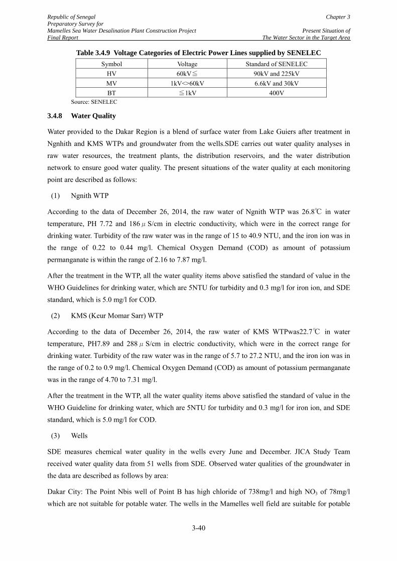
Republic of Senegal Chapter 3 Preparatory Survey for Mamelles Sea Water Desalination Plant Construction Project Present Situation of Final Report The Water Sector in the Target Area
Table 3.4.9 Voltage Categories of Electric Power Lines supplied by SENELEC Symbol Voltage Standard of SENELEC
HV 60kV≦ 90kV and 225kV MV 1kV<>60kV 6.6kV and 30kV BT ≦1kV 400V
Source: SENELEC
3.4.8 Water Quality
Water provided to the Dakar Region is a blend of surface water from Lake Guiers after treatment in Ngnhith and KMS WTPs and groundwater from the wells.SDE carries out water quality analyses in raw water resources, the treatment plants, the distribution reservoirs, and the water distribution network to ensure good water quality. The present situations of the water quality at each monitoring point are described as follows:
(1) Ngnith WTP
According to the data of December 26, 2014, the raw water of Ngnith WTP was 26.8℃ in water temperature, PH 7.72 and 186μS/cm in electric conductivity, which were in the correct range for drinking water. Turbidity of the raw water was in the range of 15 to 40.9 NTU, and the iron ion was in the range of 0.22 to 0.44 mg/l. Chemical Oxygen Demand (COD) as amount of potassium permanganate is within the range of 2.16 to 7.87 mg/l.
After the treatment in the WTP, all the water quality items above satisfied the standard of value in the WHO Guidelines for drinking water, which are 5NTU for turbidity and 0.3 mg/l for iron ion, and SDE standard, which is 5.0 mg/l for COD.
(2) KMS (Keur Momar Sarr) WTP
According to the data of December 26, 2014, the raw water of KMS WTPwas22.7℃ in water temperature, PH7.89 and 288μS/cm in electric conductivity, which were in the correct range for drinking water. Turbidity of the raw water was in the range of 5.7 to 27.2 NTU, and the iron ion was in the range of 0.2 to 0.9 mg/l. Chemical Oxygen Demand (COD) as amount of potassium permanganate was in the range of 4.70 to 7.31 mg/l.
After the treatment in the WTP, all the water quality items above satisfied the standard of value in the WHO Guideline for drinking water, which are 5NTU for turbidity and 0.3 mg/l for iron ion, and SDE standard, which is 5.0 mg/l for COD.
(3) Wells
SDE measures chemical water quality in the wells every June and December. JICA Study Team received water quality data from 51 wells from SDE. Observed water qualities of the groundwater in the data are described as follows by area:
Dakar City: The Point Nbis well of Point B has high chloride of 738mg/l and high NO3 of 78mg/l which are not suitable for potable water. The wells in the Mamelles well field are suitable for potable
3-40
Republic of Senegal Chapter 3 Preparatory Survey for Mamelles Sea Water Desalination Plant Construction Project Present Situation of Final Report The Water Sector in the Target Area
water. Four wells in Thiaroye well field were abandoned, because they have high chloride, manganese and nitrate which exceed the WHO Guideline values.
Dakar Suburb (between Thies Reservoir and Dakar): Iron ion and turbidity exceed the WHO Guideline values (0.3 mg/l and 5 NTU respectively) at all wells. The iron ion values range from 0.5 to 1.4 mg/l. The turbidity values are in proportion to iron ion values. If iron ion content is high, turbidity is also high.
Outer Suburb (between Mekhe Pumping Station and Louga): Water qualities of all wells satisfy the WHO Guideline values. According to the electrical conductivity, the water qualities of these well fields are excellent as drinking water.
(4) Distribution reservoirs
Chemical water quality in the distribution reservoirs in the Dakar Region is regularly measured by SDE. According to the 2014 monthly measurement results, there is no problem with the water quality in the reservoirs of Thies, Point B and Mamelles, which hold treated water from the Ngnith and KMS WTPs. However, iron ion exceeds the WHO Guideline values (0.3 mg/l) in most of the reservoirs which receive groundwater from the wells of Pout Kirene and Pout Sud.
(5) Distribution networks
Complying with the performance contract with SONES, SDE inspects coliform bacteria in the water distribution network throughout the whole country. According to the annual microbiological data of 2014 for the Dakar Region, 4,564 samples in total were taken from distribution pipes. As a result, bacteria were found in only 55 samples, which are 1.2 % of the total number of the samples.
3.4.9 Water Pressure
SDE installed manometer at the areas where the water deficits caused by low water pressures were reported to be significantly low to exactly identify the areas suffering from serious low pressure. Based on the measurement results, SDE has carried out improvement works at the low pressure areas as shown in Figure 3.4.10. The improvement works are to rearrange the distribution system so that the areas would be supplied by different distribution lines that have larger capacities or to shift the water source from the ALG system to the wells located near the low pressure areas.
At present, according to Figure 3.4.10, the low pressure areas are mostly located in Yoff, where the low pressure was reported in the social baseline survey in the Study as well (Refer to Table 3.3.9), and in Plateau. There used be several low pressure areas in Scap Liberte and Fronte de Terre but the improvement works have removed such areas expect for one area in Sicap Liberte.
As mentioned above, SDE is making their efforts to improve the water pressure. However, JICA Study Team points out the following difficulties and issues on the water pressure improvement:
3-41
Republic of Senegal Chapter 3 Preparatory Survey for Mamelles Sea Water Desalination Plant Construction Project Present Situation of Final Report The Water Sector in the Target Area
SDE has only 10 units of manometer. Therefore the pressure measurement points are very limited. It is anticipated that there are a large number of low pressure areas in addition to the currently measured areas.
The low pressure occurs in the activity time including the peak demand hours. Moreover, as reported in the social baseline survey in the Study, the pressure is not only low but also unstable in wide areas.
Distribution network in the Dakar 1 Zone is not sectorised into “district metered areas” (DMAs). Setup of DMA is the very essential and proven initial step to improve the water pressure and water loss management. The sectorization is necessary in the zone.
SDE has improved the water pressure in some areas by arranging the water distribution network and the water resources, but these countermeasures are emergency actions. Fundamental measures based on a comprehensive improvement plan, which takes into account the overall hydraulic situations in the entire distribution network, need to be considered. The fundamental measures will include upsizing of the existing distribution pipes and installation of booster pumps based on hydraulic calculations.
Developing areas tend to be suffering from the low pressure. The low pressure areas may expand according to further development in the Dakar 1 Zone.
3-42
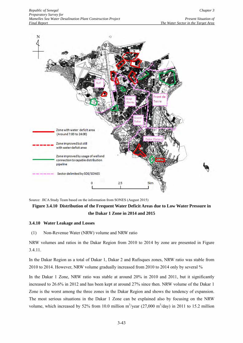
Republic of Senegal Chapter 3 Preparatory Survey for Mamelles Sea Water Desalination Plant Construction Project Present Situation of Final Report The Water Sector in the Target Area
Source: JICA Study Team based on the information from SONES (August 2015)
Figure 3.4.10 Distribution of the Frequent Water Deficit Areas due to Low Water Pressure in the Dakar 1 Zone in 2014 and 2015
3.4.10 Water Leakage and Losses
(1) Non-Revenue Water (NRW) volume and NRW ratio
NRW volumes and ratios in the Dakar Region from 2010 to 2014 by zone are presented in Figure 3.4.11.
In the Dakar Region as a total of Dakar 1, Dakar 2 and Rufisques zones, NRW ratio was stable from 2010 to 2014. However, NRW volume gradually increased from 2010 to 2014 only by several %
In the Dakar 1 Zone, NRW ratio was stable at around 20% in 2010 and 2011, but it significantly increased to 26.6% in 2012 and has been kept at around 27% since then. NRW volume of the Dakar 1 Zone is the worst among the three zones in the Dakar Region and shows the tendency of expansion. The most serious situations in the Dakar 1 Zone can be explained also by focusing on the NRW volume, which increased by 52% from 10.0 million m3/year (27,000 m3/day) in 2011 to 15.2 million
3-43
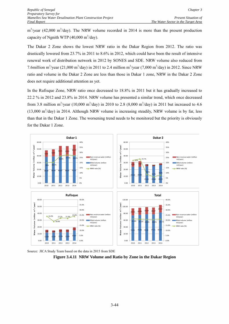
Republic of Senegal Chapter 3 Preparatory Survey for Mamelles Sea Water Desalination Plant Construction Project Present Situation of Final Report The Water Sector in the Target Area
m3/year (42,000 m3/day). The NRW volume recorded in 2014 is more than the present production capacity of Ngnith WTP (40,000 m3/day).
The Dakar 2 Zone shows the lowest NRW ratio in the Dakar Region from 2012. The ratio was drastically lowered from 23.7% in 2011 to 8.6% in 2012, which could have been the result of intensive renewal work of distribution network in 2012 by SONES and SDE. NRW volume also reduced from 7.6million m3/year (21,000 m3/day) in 2011 to 2.4 million m3/year (7,000 m3/day) in 2012. Since NRW ratio and volume in the Dakar 2 Zone are less than those in Dakar 1 zone, NRW in the Dakar 2 Zone does not require additional attention as yet.
In the Rufisque Zone, NRW ratio once decreased to 18.8% in 2011 but it has gradually increased to 22.2 % in 2012 and 23.8% in 2014. NRW volume has presented a similar trend, which once decreased from 3.8 million m3/year (10,000 m3/day) in 2010 to 2.8 (8,000 m3/day) in 2011 but increased to 4.6 (13,000 m3/day) in 2014. Although NRW volume is increasing steadily, NRW volume is by far, less than that in the Dakar 1 Zone. The worsening trend needs to be monitored but the priority is obviously for the Dakar 1 Zone.
Source: JICA Study Team based on the data in 2015 from SDE
Figure 3.4.11 NRW Volume and Ratio by Zone in the Dakar Region
12.02 12.07 12.78 12.69 14.87
3.80 2.80 3.65 3.564.64
24.0%
18.8%
22.2% 21.9%23.8%
0.0%
5.0%
10.0%
15.0%
20.0%
25.0%
30.0%
35.0%
40.0%
0.00
10.00
20.00
30.00
40.00
50.00
60.00
2010 2011 2012 2013 2014
WaterVolu
me
(million
m3/
year)
Rufisque
Non-revenue water (million m3/year)
Billed volume (million m3/year)
NRW ratio (%)
74.55 75.93 78.10 77.21 82.52
20.33 20.39 20.54 20.2722.12
21.4% 21.2% 20.8% 20.8% 21.1%
0.0%
5.0%
10.0%
15.0%
20.0%
25.0%
30.0%
35.0%
40.0%
0.00
20.00
40.00
60.00
80.00
100.00
120.00
2010 2011 2012 2013 2014
WaterVolu
me
(million
m3/
year)
Total
Non-revenue water (million m3/year)
Billed volume (million m3/year)
NRW ratio (%)
38.38 39.46 40.07 39.35 41.12
9.58 9.9914.51 15.03
15.16
20% 20.2%
26.6% 27.6% 26.9%
0%
5%
10%
15%
20%
25%
30%
35%
40%
0.00
10.00
20.00
30.00
40.00
50.00
60.00
2010 2011 2012 2013 2014
Wate
rVolum
e(m
illion
m3/
year)
Dakar 1
Non-revenue water (million m3/year)
Billed volume (million m3/year)
NRW ratio (%)
24.16 24.40
25.24 25.18 26.53
6.95 7.592.38 1.67 2.32
22%23.7%
8.6%6.2% 8.0%
0%
5%
10%
15%
20%
25%
30%
35%
40%
0.00
10.00
20.00
30.00
40.00
50.00
60.00
2010 2011 2012 2013 2014
Wate
rVolum
e(m
illion
m3/
year)
Dakar 2
Non-revenue water (million m3/year)
Billed volume (million m3/year)
NRW ratio (%)
3-44
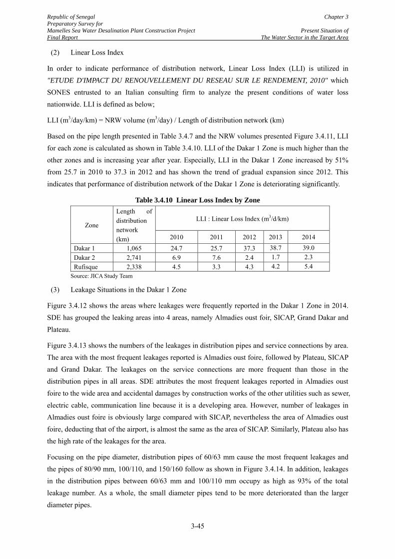
Republic of Senegal Chapter 3 Preparatory Survey for Mamelles Sea Water Desalination Plant Construction Project Present Situation of Final Report The Water Sector in the Target Area
(2) Linear Loss Index
In order to indicate performance of distribution network, Linear Loss Index (LLI) is utilized in "ETUDE D'IMPACT DU RENOUVELLEMENT DU RESEAU SUR LE RENDEMENT, 2010" which SONES entrusted to an Italian consulting firm to analyze the present conditions of water loss nationwide. LLI is defined as below;
LLI (m3/day/km) = NRW volume (m3/day) / Length of distribution network (km)
Based on the pipe length presented in Table 3.4.7 and the NRW volumes presented Figure 3.4.11, LLI for each zone is calculated as shown in Table 3.4.10. LLI of the Dakar 1 Zone is much higher than the other zones and is increasing year after year. Especially, LLI in the Dakar 1 Zone increased by 51% from 25.7 in 2010 to 37.3 in 2012 and has shown the trend of gradual expansion since 2012. This indicates that performance of distribution network of the Dakar 1 Zone is deteriorating significantly.
Table 3.4.10 Linear Loss Index by Zone
Zone
Length of distribution network (km)
LLI : Linear Loss Index (m3/d/km)
2010 2011 2012 2013 2014
Dakar 1 1,065 24.7 25.7 37.3 38.7 39.0 Dakar 2 2,741 6.9 7.6 2.4 1.7 2.3 Rufisque 2,338 4.5 3.3 4.3 4.2 5.4
Source: JICA Study Team
(3) Leakage Situations in the Dakar 1 Zone
Figure 3.4.12 shows the areas where leakages were frequently reported in the Dakar 1 Zone in 2014. SDE has grouped the leaking areas into 4 areas, namely Almadies oust foir, SICAP, Grand Dakar and Plateau.
Figure 3.4.13 shows the numbers of the leakages in distribution pipes and service connections by area. The area with the most frequent leakages reported is Almadies oust foire, followed by Plateau, SICAP and Grand Dakar. The leakages on the service connections are more frequent than those in the distribution pipes in all areas. SDE attributes the most frequent leakages reported in Almadies oust foire to the wide area and accidental damages by construction works of the other utilities such as sewer, electric cable, communication line because it is a developing area. However, number of leakages in Almadies oust foire is obviously large compared with SICAP, nevertheless the area of Almadies oust foire, deducting that of the airport, is almost the same as the area of SICAP. Similarly, Plateau also has the high rate of the leakages for the area.
Focusing on the pipe diameter, distribution pipes of 60/63 mm cause the most frequent leakages and the pipes of 80/90 mm, 100/110, and 150/160 follow as shown in Figure 3.4.14. In addition, leakages in the distribution pipes between 60/63 mm and 100/110 mm occupy as high as 93% of the total leakage number. As a whole, the small diameter pipes tend to be more deteriorated than the larger diameter pipes.
3-45
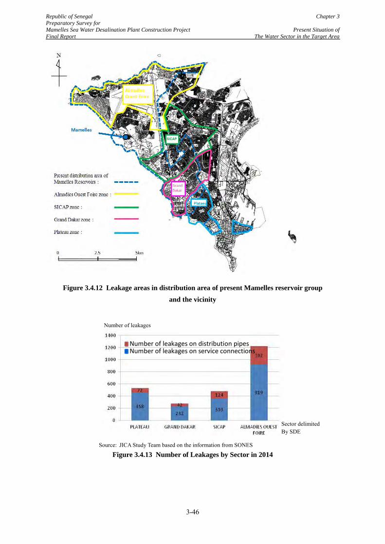
Republic of Senegal Chapter 3 Preparatory Survey for Mamelles Sea Water Desalination Plant Construction Project Present Situation of Final Report The Water Sector in the Target Area
Figure 3.4.12 Leakage areas in distribution area of present Mamelles reservoir group and the vicinity
Source: JICA Study Team based on the information from SONES
Figure 3.4.13 Number of Leakages by Sector in 2014
Number of leakages on distribution pipes
Number of leakages on service connections
Number of leakages
Sector delimited By SDE
3-46
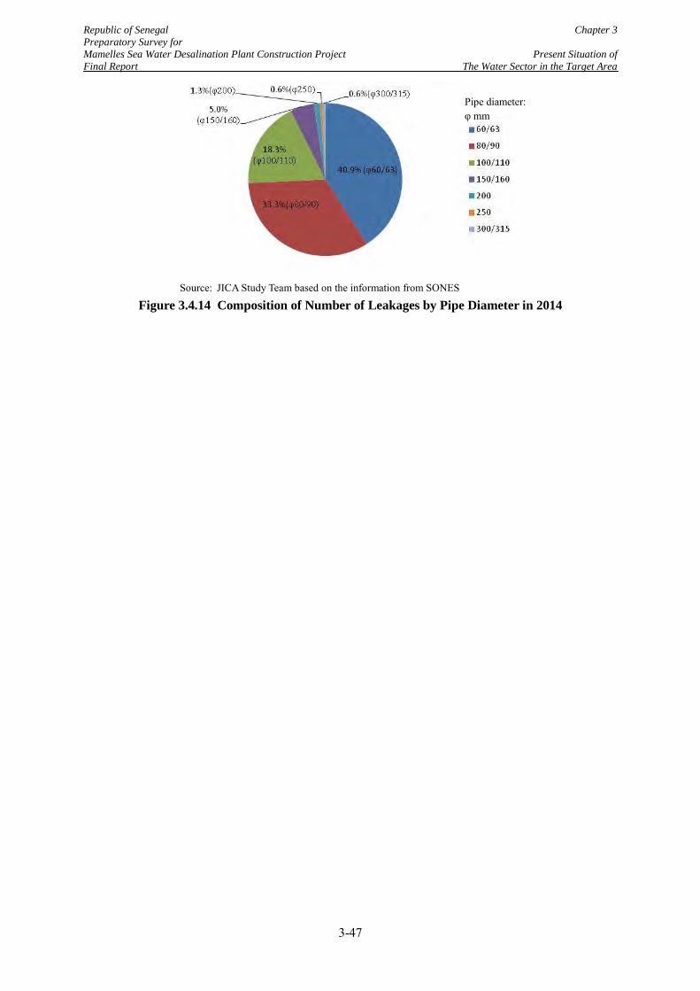
Republic of Senegal Chapter 3 Preparatory Survey for Mamelles Sea Water Desalination Plant Construction Project Present Situation of Final Report The Water Sector in the Target Area
Source: JICA Study Team based on the information from SONES
Figure 3.4.14 Composition of Number of Leakages by Pipe Diameter in 2014
Pipe diameter: φ mm
3-47
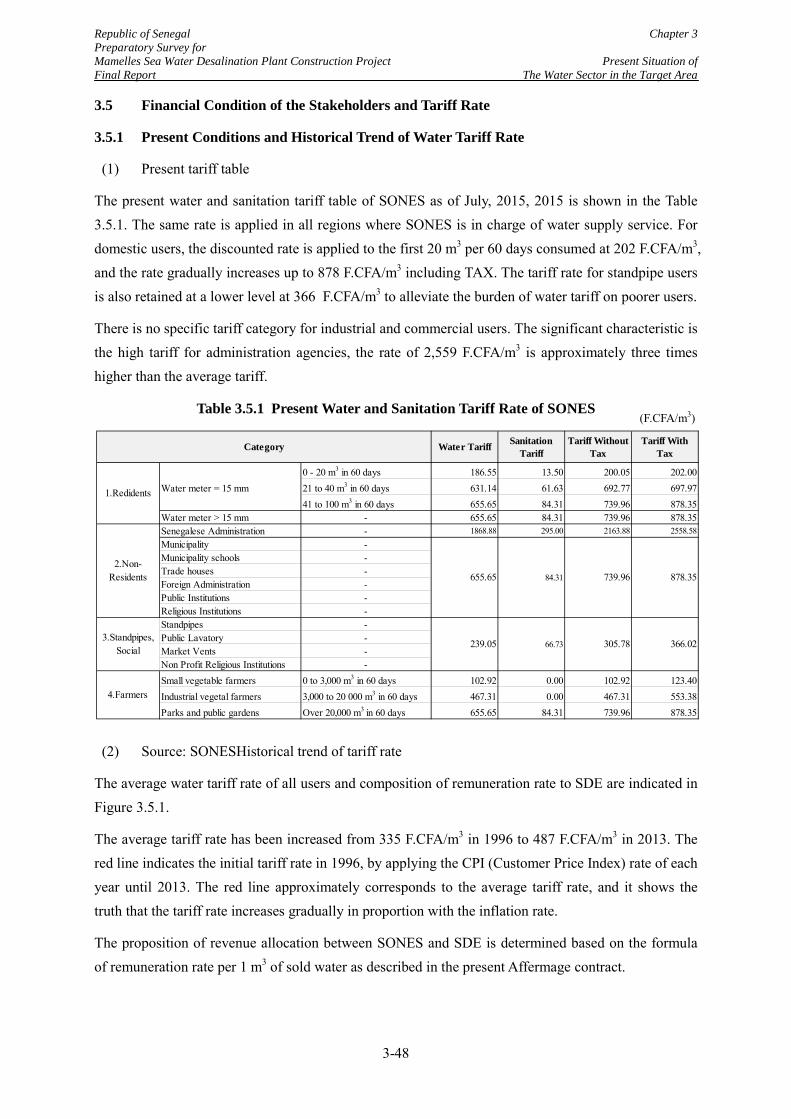
Republic of Senegal Chapter 3 Preparatory Survey for Mamelles Sea Water Desalination Plant Construction Project Present Situation of Final Report The Water Sector in the Target Area
3.5 Financial Condition of the Stakeholders and Tariff Rate
3.5.1 Present Conditions and Historical Trend of Water Tariff Rate
(1) Present tariff table
The present water and sanitation tariff table of SONES as of July, 2015, 2015 is shown in the Table 3.5.1. The same rate is applied in all regions where SONES is in charge of water supply service. For domestic users, the discounted rate is applied to the first 20 m3 per 60 days consumed at 202 F.CFA/m3, and the rate gradually increases up to 878 F.CFA/m3 including TAX. The tariff rate for standpipe users is also retained at a lower level at 366 F.CFA/m3 to alleviate the burden of water tariff on poorer users.
There is no specific tariff category for industrial and commercial users. The significant characteristic is the high tariff for administration agencies, the rate of 2,559 F.CFA/m3 is approximately three times higher than the average tariff.
Table 3.5.1 Present Water and Sanitation Tariff Rate of SONES
(2) Source: SONESHistorical trend of tariff rate
The average water tariff rate of all users and composition of remuneration rate to SDE are indicated in Figure 3.5.1.
The average tariff rate has been increased from 335 F.CFA/m3 in 1996 to 487 F.CFA/m3 in 2013. The red line indicates the initial tariff rate in 1996, by applying the CPI (Customer Price Index) rate of each year until 2013. The red line approximately corresponds to the average tariff rate, and it shows the truth that the tariff rate increases gradually in proportion with the inflation rate.
The proposition of revenue allocation between SONES and SDE is determined based on the formula of remuneration rate per 1 m3 of sold water as described in the present Affermage contract.
0 - 20 m3 in 60 days 186.55 13.50 200.05 202.00Water meter = 15 mm 21 to 40 m3 in 60 days 631.14 61.63 692.77 697.97
41 to 100 m3 in 60 days 655.65 84.31 739.96 878.35Water meter > 15 mm - 655.65 84.31 739.96 878.35Senegalese Administration - 1868.88 295.00 2163.88 2558.58Municipality -Municipality schools -Trade houses -Foreign Administration -Public Institutions -Religious Institutions -Standpipes -Public Lavatory -Market Vents -Non Profit Religious Institutions -Small vegetable farmers 0 to 3,000 m3 in 60 days 102.92 0.00 102.92 123.40Industrial vegetal farmers 3,000 to 20 000 m3 in 60 days 467.31 0.00 467.31 553.38Parks and public gardens Over 20,000 m3 in 60 days 655.65 84.31 739.96 878.35
Tariff WithoutTax
Tariff WithTax
878.35
366.02305.78
739.96
239.05
SanitationTariff
Category
66.73
Water Tariff
84.31655.65
4.Farmers
1.Redidents
3.Standpipes,Social
2.Non-Residents
(F.CFA/m3)
3-48
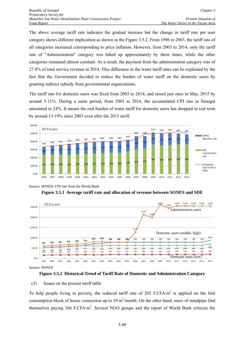
Republic of Senegal Chapter 3 Preparatory Survey for Mamelles Sea Water Desalination Plant Construction Project Present Situation of Final Report The Water Sector in the Target Area
The above average tariff rate indicates the gradual increase but the change in tariff rate per user category shows different implication as shown in the Figure 3.5.2. From 1996 to 2003, the tariff rate of all categories increased corresponding to price inflation. However, from 2003 to 2014, only the tariff rate of "Administration" category was hiked up approximately by three times, while the other categories remained almost constant. As a result, the payment from the administration category was of 27.8% of total service revenue in 2014. This difference in the water tariff rates can be explained by the fact that the Government decided to reduce the burden of water tariff on the domestic users by granting indirect subsidy from governmental organizations.
The tariff rate for domestic users was fixed from 2003 to 2014, and raised just once in May, 2015 by around 5-11%. During a same period, from 2003 to 2014, the accumulated CPI rate in Senegal amounted to 24%. It means the real burden of water tariff for domestic users has dropped in real term by around 13-19% since 2003 even after the 2015 tariff.
Source: SONES, CPI rate from the World Bank
Figure 3.5.1 Average tariff rate and allocation of revenue between SONES and SDE
Source: SONES
Figure 3.5.2 Historical Trend of Tariff Rate of Domestic and Administration Category
(3) Issues on the present tariff table
To help people living in poverty, the reduced tariff rate of 202 F.CFA/m3 is applied on the first consumption block of house connection up to 10 m3/month. On the other hand, users of standpipe find themselves paying 366 F.CFA/m3. Several NGO groups and the report of World Bank criticize the
235 240 240 235 243 246 251 258 258 260 279 301 316 361 349 356 364 364
100 110 117 136 139 141 140 144 146 143 141 164 150
149 150 148 133 123
335 350 357 370 382 387 391 402 404 403 420 466 466
510 500 504 497 487
0.00
100.00
200.00
300.00
400.00
500.00
600.00
1996 1997 1998 1999 2000 2001 2002 2003 2004 2005 2006 2007 2008 2009 2010 2011 2012 2013
SONES allocation rate
SDE remuneration rate
CPI applied Total Tariff in 1996
157 161 165 170 175 182 172 176 191 191 191 191 191 191 191 191 191 191 191 191 202 534 548 563 588 605 631 599 614 630 630 630 630 630 630 630 630 630 630 630 630 698
614 630 647 674 694 724 810 829 789 789 789 789 789 789 789 789 789 789 789 789
878
614 630 647 674 694 724 810 829 789 789 789
1,277
2,141 1,996
2,620 2,445
2,559 2,559 2,559 2,559 2,559
0.00
500.00
1000.00
1500.00
2000.00
2500.00
1995 1996 1997 1998 1999 2000 2001 2002 2003 2004 2005 2006 2007 2008 2009 2010 2011 2012 2013 2014 2015
Administration users
Domestic users (middle, high)
Domestic users (low)
(FCFA/m3)
(FCFA/m3)
3-49
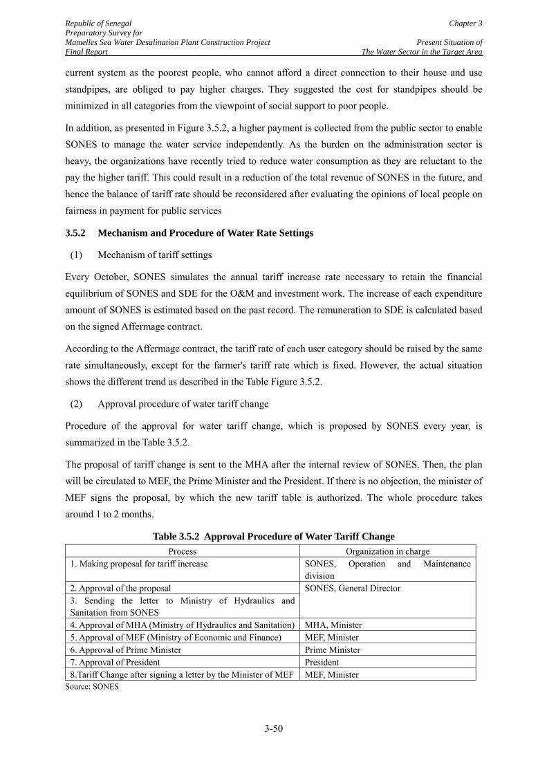
Republic of Senegal Chapter 3 Preparatory Survey for Mamelles Sea Water Desalination Plant Construction Project Present Situation of Final Report The Water Sector in the Target Area
current system as the poorest people, who cannot afford a direct connection to their house and use standpipes, are obliged to pay higher charges. They suggested the cost for standpipes should be minimized in all categories from the viewpoint of social support to poor people.
In addition, as presented in Figure 3.5.2, a higher payment is collected from the public sector to enable SONES to manage the water service independently. As the burden on the administration sector is heavy, the organizations have recently tried to reduce water consumption as they are reluctant to the pay the higher tariff. This could result in a reduction of the total revenue of SONES in the future, and hence the balance of tariff rate should be reconsidered after evaluating the opinions of local people on fairness in payment for public services
3.5.2 Mechanism and Procedure of Water Rate Settings
(1) Mechanism of tariff settings
Every October, SONES simulates the annual tariff increase rate necessary to retain the financial equilibrium of SONES and SDE for the O&M and investment work. The increase of each expenditure amount of SONES is estimated based on the past record. The remuneration to SDE is calculated based on the signed Affermage contract.
According to the Affermage contract, the tariff rate of each user category should be raised by the same rate simultaneously, except for the farmer's tariff rate which is fixed. However, the actual situation shows the different trend as described in the Table Figure 3.5.2.
(2) Approval procedure of water tariff change
Procedure of the approval for water tariff change, which is proposed by SONES every year, is summarized in the Table 3.5.2.
The proposal of tariff change is sent to the MHA after the internal review of SONES. Then, the plan will be circulated to MEF, the Prime Minister and the President. If there is no objection, the minister of MEF signs the proposal, by which the new tariff table is authorized. The whole procedure takes around 1 to 2 months.
Table 3.5.2 Approval Procedure of Water Tariff Change Process Organization in charge
1. Making proposal for tariff increase SONES, Operation and Maintenance division
2. Approval of the proposal SONES, General Director 3. Sending the letter to Ministry of Hydraulics and Sanitation from SONES 4. Approval of MHA (Ministry of Hydraulics and Sanitation) MHA, Minister 5. Approval of MEF (Ministry of Economic and Finance) MEF, Minister 6. Approval of Prime Minister Prime Minister 7. Approval of President President 8.Tariff Change after signing a letter by the Minister of MEF MEF, Minister
Source: SONES
3-50
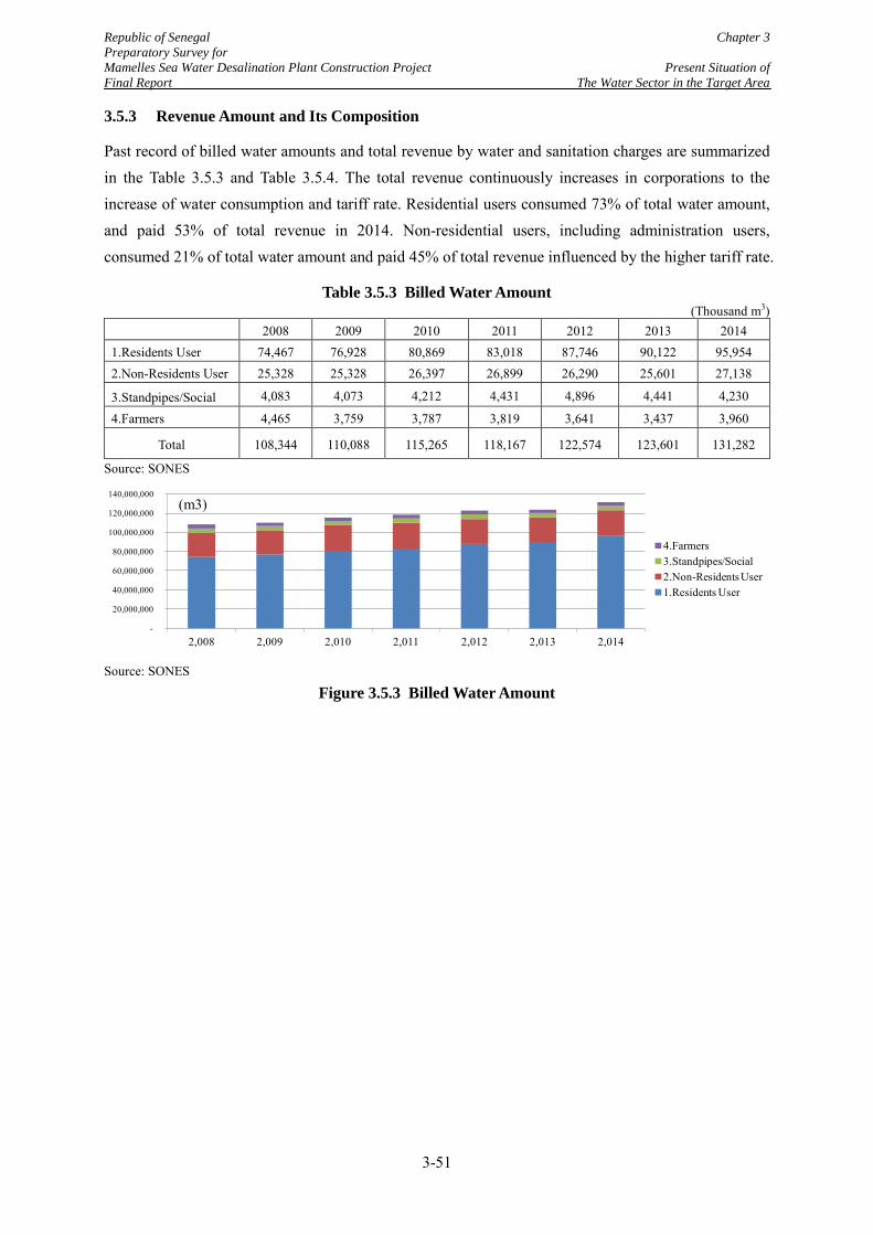
Republic of Senegal Chapter 3 Preparatory Survey for Mamelles Sea Water Desalination Plant Construction Project Present Situation of Final Report The Water Sector in the Target Area
3.5.3 Revenue Amount and Its Composition
Past record of billed water amounts and total revenue by water and sanitation charges are summarized in the Table 3.5.3 and Table 3.5.4. The total revenue continuously increases in corporations to the increase of water consumption and tariff rate. Residential users consumed 73% of total water amount, and paid 53% of total revenue in 2014. Non-residential users, including administration users, consumed 21% of total water amount and paid 45% of total revenue influenced by the higher tariff rate.
Table 3.5.3 Billed Water Amount (Thousand m3)
2008 2009 2010 2011 2012 2013 2014
1.Residents User 74,467 76,928 80,869 83,018 87,746 90,122 95,954 2.Non-Residents User 25,328 25,328 26,397 26,899 26,290 25,601 27,138
3.Standpipes/Social 4,083 4,073 4,212 4,431 4,896 4,441 4,230
4.Farmers 4,465 3,759 3,787 3,819 3,641 3,437 3,960
Total 108,344 110,088 115,265 118,167 122,574 123,601 131,282
Source: SONES
Source: SONES
Figure 3.5.3 Billed Water Amount
-
20,000,000
40,000,000
60,000,000
80,000,000
100,000,000
120,000,000
140,000,000
2,008 2,009 2,010 2,011 2,012 2,013 2,014
4.Farmers3.Standpipes/Social2.Non-Residents User1.Residents User
(m3)
3-51
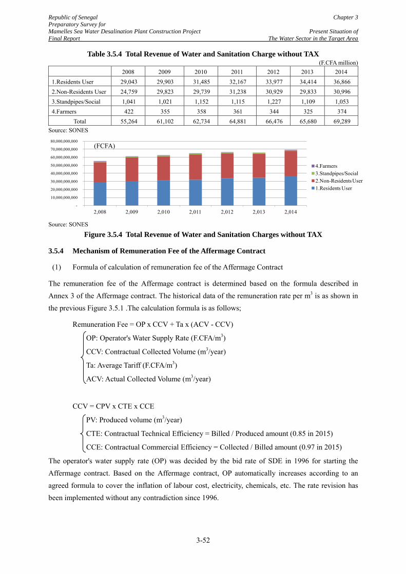
Republic of Senegal Chapter 3 Preparatory Survey for Mamelles Sea Water Desalination Plant Construction Project Present Situation of Final Report The Water Sector in the Target Area
Table 3.5.4 Total Revenue of Water and Sanitation Charge without TAX (F.CFA million)
2008 2009 2010 2011 2012 2013 2014 1.Residents User 29,043 29,903 31,485 32,167 33,977 34,414 36,866 2.Non-Residents User 24,759 29,823 29,739 31,238 30,929 29,833 30,996 3.Standpipes/Social 1,041 1,021 1,152 1,115 1,227 1,109 1,053 4.Farmers 422 355 358 361 344 325 374
Total 55,264 61,102 62,734 64,881 66,476 65,680 69,289 Source: SONES
Source: SONES
Figure 3.5.4 Total Revenue of Water and Sanitation Charges without TAX
3.5.4 Mechanism of Remuneration Fee of the Affermage Contract
(1) Formula of calculation of remuneration fee of the Affermage Contract
The remuneration fee of the Affermage contract is determined based on the formula described in Annex 3 of the Affermage contract. The historical data of the remuneration rate per m3 is as shown in the previous Figure 3.5.1 .The calculation formula is as follows;
Remuneration Fee = OP x CCV + Ta x (ACV - CCV)
OP: Operator's Water Supply Rate (F.CFA/m3)
CCV: Contractual Collected Volume (m3/year)
Ta: Average Tariff (F.CFA/m3)
ACV: Actual Collected Volume (m3/year)
CCV = CPV x CTE x CCE
PV: Produced volume (m3/year)
CTE: Contractual Technical Efficiency = Billed / Produced amount (0.85 in 2015)
CCE: Contractual Commercial Efficiency = Collected / Billed amount (0.97 in 2015)
The operator's water supply rate (OP) was decided by the bid rate of SDE in 1996 for starting the Affermage contract. Based on the Affermage contract, OP automatically increases according to an agreed formula to cover the inflation of labour cost, electricity, chemicals, etc. The rate revision has been implemented without any contradiction since 1996.
-
10,000,000,000
20,000,000,000
30,000,000,000
40,000,000,000
50,000,000,000
60,000,000,000
70,000,000,000
80,000,000,000
2,008 2,009 2,010 2,011 2,012 2,013 2,014
4.Farmers3.Standpipes/Social2.Non-Residents User1.Residents User
(FCFA)
3-52
Republic of Senegal Chapter 3 Preparatory Survey for Mamelles Sea Water Desalination Plant Construction Project Present Situation of Final Report The Water Sector in the Target Area
The existence of a gap between the "actual" collected volume (ACV) and "contractual" collected volume (CCV) works as the incentive mechanism embedded in the Affermage contract so as to maximize total revenue of the service. The said difference can affect either positively or negatively the remuneration amount of SDE.
The CCV is calculated by multiplying the produced volume, CTE and CCE. The latter two indexes are determined at 0.85 and 0.97 for 2014 by the contract, while the actual "Technical efficiency" and "Commercial Efficiency" in 2014 was 0.81 and 0.98 respectively. Therefore, SDE's remuneration is reduced by the gap between the actual and contractual numbers under the present condition. SDE has been complaining that the CTE is too high under real conditions of network facilities, though the target has not been changed.
(2) Advantage of the remuneration formula in the Affermage scheme
Related to the formula above, the report issued by the World Bank "Innovative Contracts, Sound Relationships: Urban Water Sector Reform in Senegal (2004)" pointed out the merit of this Affermage contract compared with the usual full concession scheme. In the full concession scheme, the operator is reluctant to divert water from rich areas to poor areas, as their revenue tends to be shrunken as the tariff rate in poor areas tends to be lower, the aim of the pro-poor policy. Under the Affermage scheme of Senegal, as the remuneration to SDE is purely dependant on the collected volume, the private sector is simply motivated to expand their services without considering the nominal revenue amount expected from the expansion. It is one of the merits of the Affermage scheme in Senegal, compared with the usual full concession scheme.
(3) Penalties in the Affermage Contract
In addition to the embedded reward and penalty mechanism in the formula for calculating the remuneration, the other penalty is stipulated in the Affermage contract (article 5). The interruption of water supply and low pressure is supposed to be charged by SONES based on the stipulated formula, duration and affected user amount. However, the indicators related to service continuity and water pressure are not included in the performance indicators and the monitoring process is not clearly mentioned in the contract. Thereby, such penalties have not been implemented in the past.
3.5.5 Financial Condition of SONES and SDE
This part was omitted due to confidentiality.
3-53
Republic of Senegal Chapter 3 Preparatory Survey for Mamelles Sea Water Desalination Plant Construction Project Present Situation of Final Report The Water Sector in the Target Area
This part was omitted due to confidentiality.
3-54
Republic of Senegal Chapter 3 Preparatory Survey for Mamelles Sea Water Desalination Plant Construction Project Present Situation of Final Report The Water Sector in the Target Area
Table 3.5.5 Financial Statements of SONES
(1) The Financial conditions of SDE
This part was omitted due to confidentiality.
This part was omitted due to confidentiality.
3-55
Republic of Senegal Chapter 3 Preparatory Survey for Mamelles Sea Water Desalination Plant Construction Project Present Situation of Final Report The Water Sector in the Target Area
Table 3.5.6 Financial Statements of SDE
As mentioned above, the financial condition of SDE is considered healthy, but the following risks should be noted to ensure a sustainable management.
1) Avoid serious water supply suspension for long periods
Some technical problems, such as breakage of main pipes or contamination of water treatment plants, result in the reduction of collected water volume. Even if the water interruption was caused by the lack
This part was omitted due to confidentiality.
3-56
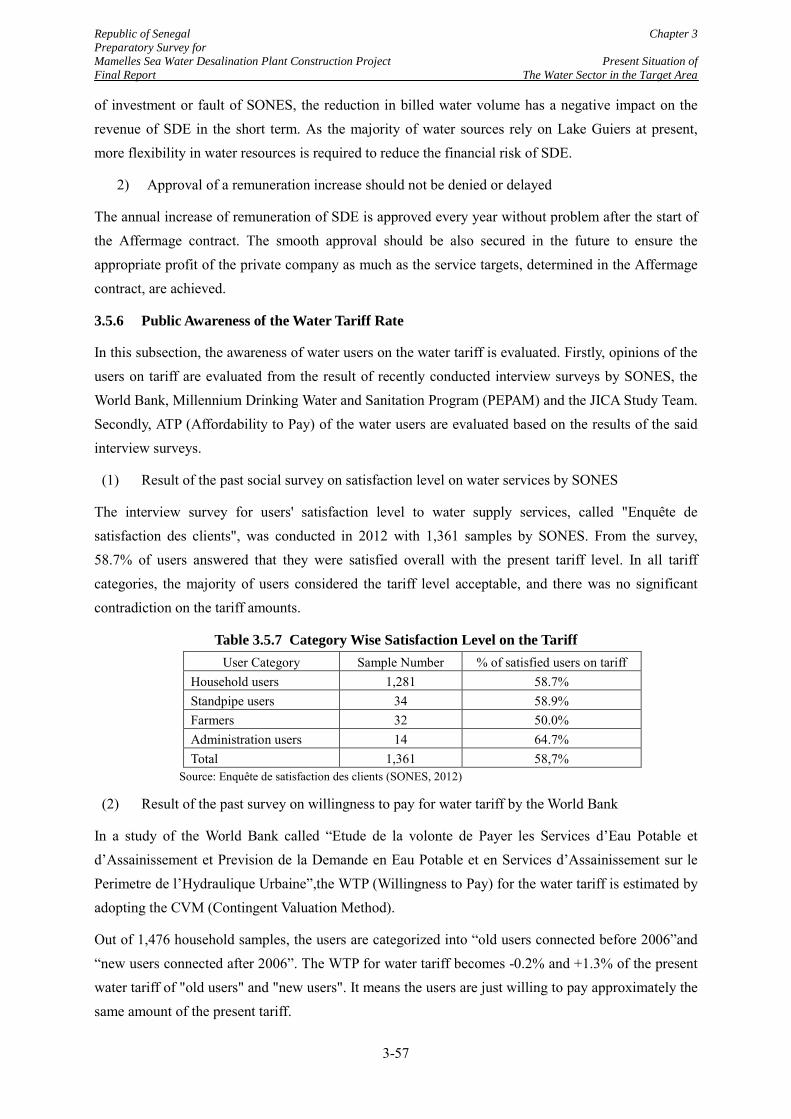
Republic of Senegal Chapter 3 Preparatory Survey for Mamelles Sea Water Desalination Plant Construction Project Present Situation of Final Report The Water Sector in the Target Area
of investment or fault of SONES, the reduction in billed water volume has a negative impact on the revenue of SDE in the short term. As the majority of water sources rely on Lake Guiers at present, more flexibility in water resources is required to reduce the financial risk of SDE.
2) Approval of a remuneration increase should not be denied or delayed
The annual increase of remuneration of SDE is approved every year without problem after the start of the Affermage contract. The smooth approval should be also secured in the future to ensure the appropriate profit of the private company as much as the service targets, determined in the Affermage contract, are achieved.
3.5.6 Public Awareness of the Water Tariff Rate
In this subsection, the awareness of water users on the water tariff is evaluated. Firstly, opinions of the users on tariff are evaluated from the result of recently conducted interview surveys by SONES, the World Bank, Millennium Drinking Water and Sanitation Program (PEPAM) and the JICA Study Team. Secondly, ATP (Affordability to Pay) of the water users are evaluated based on the results of the said interview surveys.
(1) Result of the past social survey on satisfaction level on water services by SONES
The interview survey for users' satisfaction level to water supply services, called "Enquête de satisfaction des clients", was conducted in 2012 with 1,361 samples by SONES. From the survey, 58.7% of users answered that they were satisfied overall with the present tariff level. In all tariff categories, the majority of users considered the tariff level acceptable, and there was no significant contradiction on the tariff amounts.
Table 3.5.7 Category Wise Satisfaction Level on the Tariff User Category Sample Number % of satisfied users on tariff
Household users 1,281 58.7% Standpipe users 34 58.9% Farmers 32 50.0% Administration users 14 64.7% Total 1,361 58,7%
Source: Enquête de satisfaction des clients (SONES, 2012)
(2) Result of the past survey on willingness to pay for water tariff by the World Bank
In a study of the World Bank called “Etude de la volonte de Payer les Services d’Eau Potable et d’Assainissement et Prevision de la Demande en Eau Potable et en Services d’Assainissement sur le Perimetre de l’Hydraulique Urbaine”,the WTP (Willingness to Pay) for the water tariff is estimated by adopting the CVM (Contingent Valuation Method).
Out of 1,476 household samples, the users are categorized into “old users connected before 2006”and “new users connected after 2006”. The WTP for water tariff becomes -0.2% and +1.3% of the present water tariff of "old users" and "new users". It means the users are just willing to pay approximately the same amount of the present tariff.
3-57
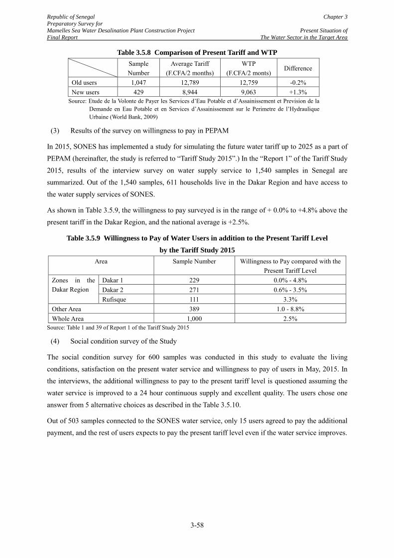
Republic of Senegal Chapter 3 Preparatory Survey for Mamelles Sea Water Desalination Plant Construction Project Present Situation of Final Report The Water Sector in the Target Area
Table 3.5.8 Comparison of Present Tariff and WTP Sample
Number Average Tariff
(F.CFA/2 months) WTP
(F.CFA/2 monts) Difference
Old users 1,047 12,789 12,759 -0.2% New users 429 8,944 9,063 +1.3%
Source: Etude de la Volonte de Payer les Services d’Eau Potable et d’Assainissement et Prevision de la Demande en Eau Potable et en Services d’Assainissement sur le Perimetre de l’Hydraulique Urbaine (World Bank, 2009)
(3) Results of the survey on willingness to pay in PEPAM
In 2015, SONES has implemented a study for simulating the future water tariff up to 2025 as a part of PEPAM (hereinafter, the study is referred to “Tariff Study 2015”.) In the “Report 1” of the Tariff Study 2015, results of the interview survey on water supply service to 1,540 samples in Senegal are summarized. Out of the 1,540 samples, 611 households live in the Dakar Region and have access to the water supply services of SONES.
As shown in Table 3.5.9, the willingness to pay surveyed is in the range of + 0.0% to +4.8% above the present tariff in the Dakar Region, and the national average is +2.5%.
Table 3.5.9 Willingness to Pay of Water Users in addition to the Present Tariff Level by the Tariff Study 2015
Area Sample Number Willingness to Pay compared with the Present Tariff Level
Zones in the Dakar Region
Dakar 1 229 0.0% - 4.8% Dakar 2 271 0.6% - 3.5% Rufisque 111 3.3%
Other Area 389 1.0 - 8.8% Whole Area 1,000 2.5%
Source: Table 1 and 39 of Report 1 of the Tariff Study 2015
(4) Social condition survey of the Study
The social condition survey for 600 samples was conducted in this study to evaluate the living conditions, satisfaction on the present water service and willingness to pay of users in May, 2015. In the interviews, the additional willingness to pay to the present tariff level is questioned assuming the water service is improved to a 24 hour continuous supply and excellent quality. The users chose one answer from 5 alternative choices as described in the Table 3.5.10.
Out of 503 samples connected to the SONES water service, only 15 users agreed to pay the additional payment, and the rest of users expects to pay the present tariff level even if the water service improves.
3-58
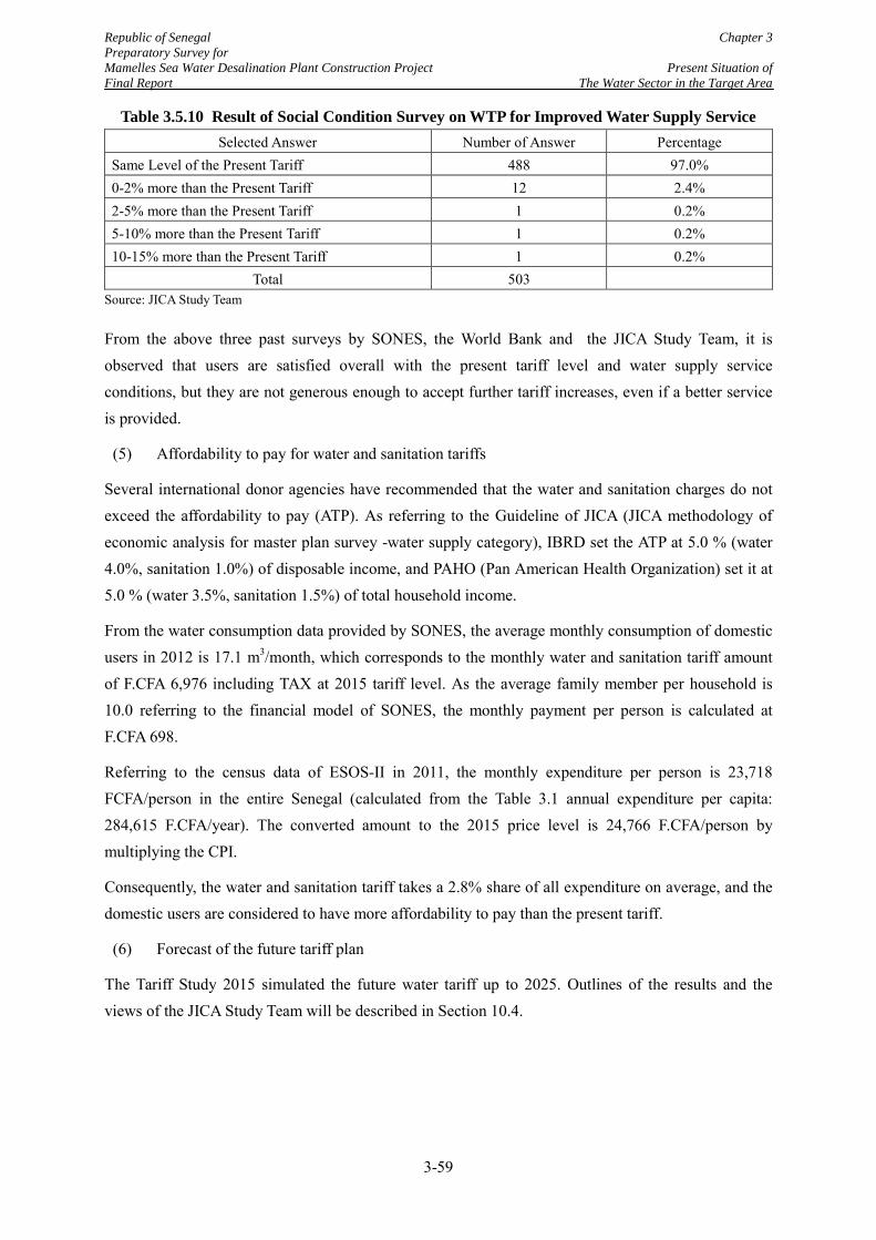
Republic of Senegal Chapter 3 Preparatory Survey for Mamelles Sea Water Desalination Plant Construction Project Present Situation of Final Report The Water Sector in the Target Area
Table 3.5.10 Result of Social Condition Survey on WTP for Improved Water Supply Service Selected Answer Number of Answer Percentage
Same Level of the Present Tariff 488 97.0% 0-2% more than the Present Tariff 12 2.4% 2-5% more than the Present Tariff 1 0.2% 5-10% more than the Present Tariff 1 0.2% 10-15% more than the Present Tariff 1 0.2%
Total 503
Source: JICA Study Team
From the above three past surveys by SONES, the World Bank and the JICA Study Team, it is observed that users are satisfied overall with the present tariff level and water supply service conditions, but they are not generous enough to accept further tariff increases, even if a better service is provided.
(5) Affordability to pay for water and sanitation tariffs
Several international donor agencies have recommended that the water and sanitation charges do not exceed the affordability to pay (ATP). As referring to the Guideline of JICA (JICA methodology of economic analysis for master plan survey -water supply category), IBRD set the ATP at 5.0 % (water 4.0%, sanitation 1.0%) of disposable income, and PAHO (Pan American Health Organization) set it at 5.0 % (water 3.5%, sanitation 1.5%) of total household income.
From the water consumption data provided by SONES, the average monthly consumption of domestic users in 2012 is 17.1 m3/month, which corresponds to the monthly water and sanitation tariff amount of F.CFA 6,976 including TAX at 2015 tariff level. As the average family member per household is 10.0 referring to the financial model of SONES, the monthly payment per person is calculated at F.CFA 698.
Referring to the census data of ESOS-II in 2011, the monthly expenditure per person is 23,718 FCFA/person in the entire Senegal (calculated from the Table 3.1 annual expenditure per capita: 284,615 F.CFA/year). The converted amount to the 2015 price level is 24,766 F.CFA/person by multiplying the CPI.
Consequently, the water and sanitation tariff takes a 2.8% share of all expenditure on average, and the domestic users are considered to have more affordability to pay than the present tariff.
(6) Forecast of the future tariff plan
The Tariff Study 2015 simulated the future water tariff up to 2025. Outlines of the results and the views of the JICA Study Team will be described in Section 10.4.
3-59
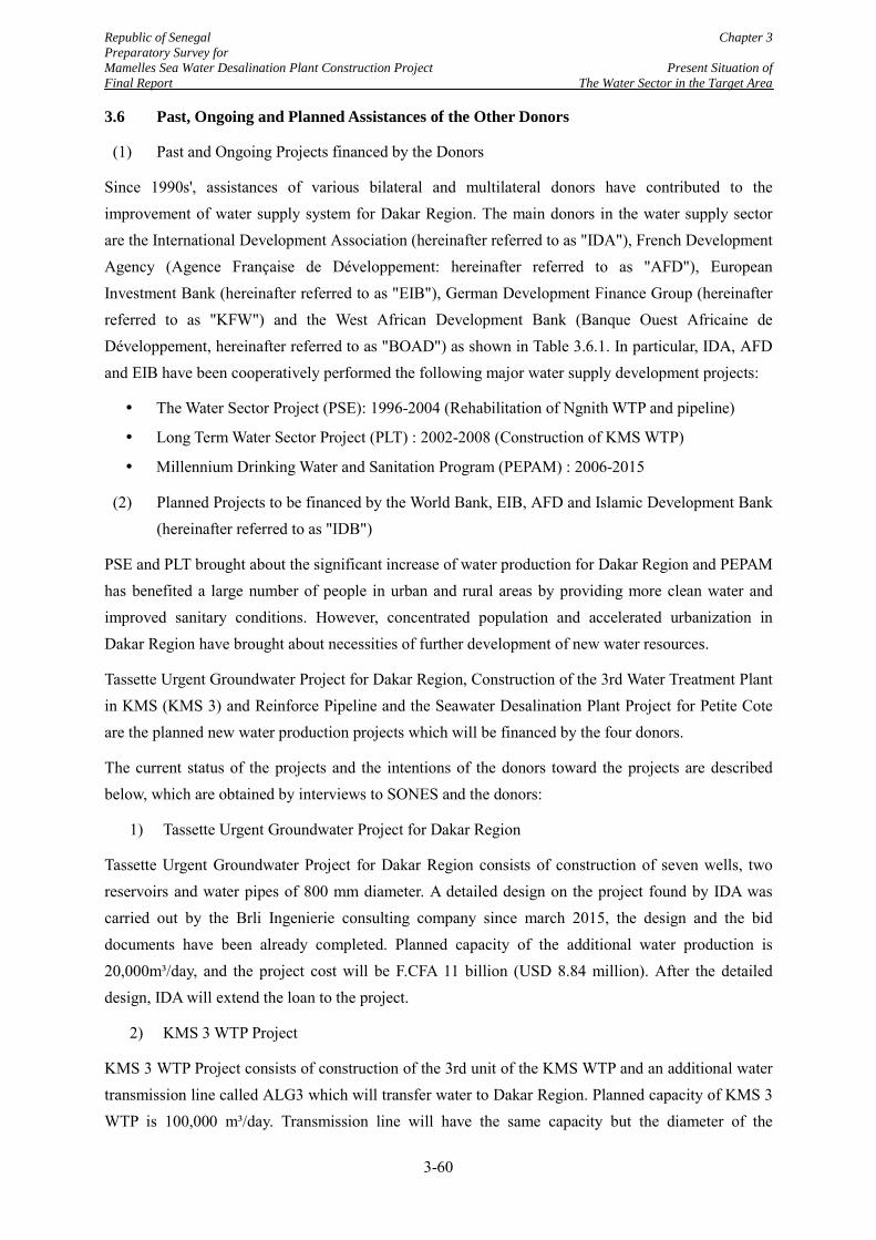
Republic of Senegal Chapter 3 Preparatory Survey for Mamelles Sea Water Desalination Plant Construction Project Present Situation of Final Report The Water Sector in the Target Area
3.6 Past, Ongoing and Planned Assistances of the Other Donors
(1) Past and Ongoing Projects financed by the Donors
Since 1990s', assistances of various bilateral and multilateral donors have contributed to the improvement of water supply system for Dakar Region. The main donors in the water supply sector are the International Development Association (hereinafter referred to as "IDA"), French Development Agency (Agence Française de Développement: hereinafter referred to as "AFD"), European Investment Bank (hereinafter referred to as "EIB"), German Development Finance Group (hereinafter referred to as "KFW") and the West African Development Bank (Banque Ouest Africaine de Développement, hereinafter referred to as "BOAD") as shown in Table 3.6.1. In particular, IDA, AFD and EIB have been cooperatively performed the following major water supply development projects:
The Water Sector Project (PSE): 1996-2004 (Rehabilitation of Ngnith WTP and pipeline)
Long Term Water Sector Project (PLT) : 2002-2008 (Construction of KMS WTP)
Millennium Drinking Water and Sanitation Program (PEPAM) : 2006-2015
(2) Planned Projects to be financed by the World Bank, EIB, AFD and Islamic Development Bank (hereinafter referred to as "IDB")
PSE and PLT brought about the significant increase of water production for Dakar Region and PEPAM has benefited a large number of people in urban and rural areas by providing more clean water and improved sanitary conditions. However, concentrated population and accelerated urbanization in Dakar Region have brought about necessities of further development of new water resources.
Tassette Urgent Groundwater Project for Dakar Region, Construction of the 3rd Water Treatment Plant in KMS (KMS 3) and Reinforce Pipeline and the Seawater Desalination Plant Project for Petite Cote are the planned new water production projects which will be financed by the four donors.
The current status of the projects and the intentions of the donors toward the projects are described below, which are obtained by interviews to SONES and the donors:
1) Tassette Urgent Groundwater Project for Dakar Region
Tassette Urgent Groundwater Project for Dakar Region consists of construction of seven wells, two reservoirs and water pipes of 800 mm diameter. A detailed design on the project found by IDA was carried out by the Brli Ingenierie consulting company since march 2015, the design and the bid documents have been already completed. Planned capacity of the additional water production is 20,000m³/day, and the project cost will be F.CFA 11 billion (USD 8.84 million). After the detailed design, IDA will extend the loan to the project.
2) KMS 3 WTP Project
KMS 3 WTP Project consists of construction of the 3rd unit of the KMS WTP and an additional water transmission line called ALG3 which will transfer water to Dakar Region. Planned capacity of KMS 3 WTP is 100,000 m³/day. Transmission line will have the same capacity but the diameter of the
3-60
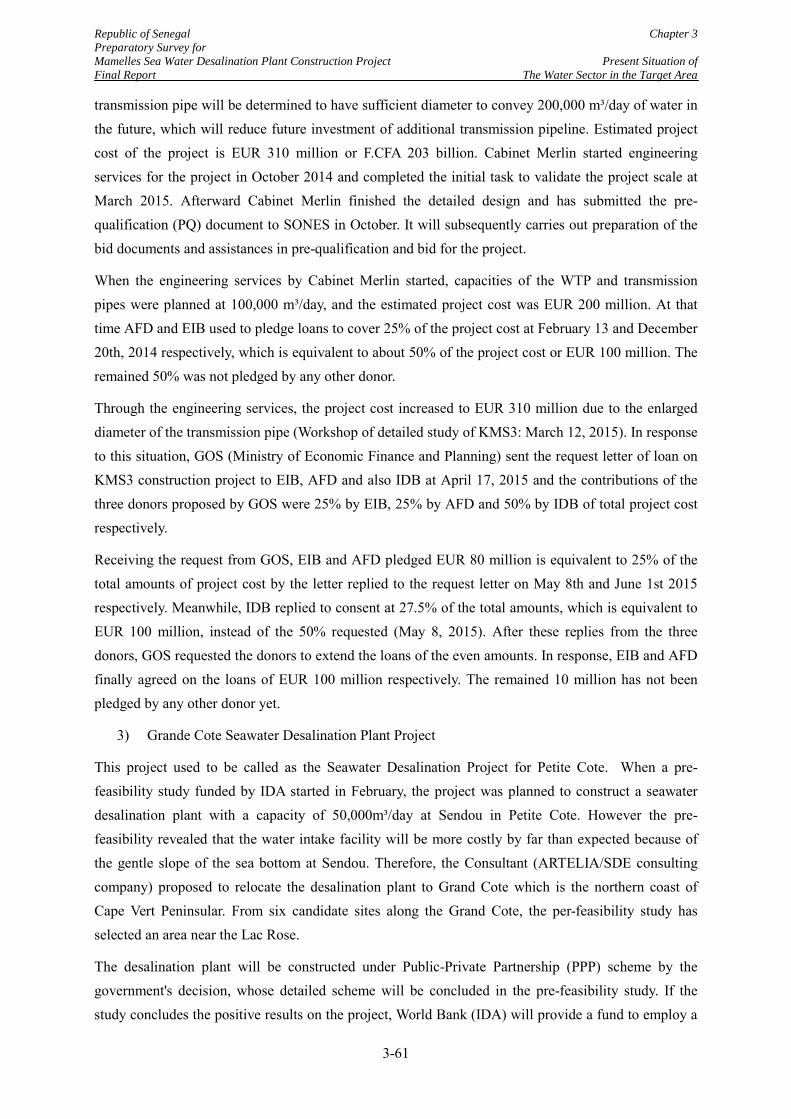
Republic of Senegal Chapter 3 Preparatory Survey for Mamelles Sea Water Desalination Plant Construction Project Present Situation of Final Report The Water Sector in the Target Area
transmission pipe will be determined to have sufficient diameter to convey 200,000 m³/day of water in the future, which will reduce future investment of additional transmission pipeline. Estimated project cost of the project is EUR 310 million or F.CFA 203 billion. Cabinet Merlin started engineering services for the project in October 2014 and completed the initial task to validate the project scale at March 2015. Afterward Cabinet Merlin finished the detailed design and has submitted the pre-qualification (PQ) document to SONES in October. It will subsequently carries out preparation of the bid documents and assistances in pre-qualification and bid for the project.
When the engineering services by Cabinet Merlin started, capacities of the WTP and transmission pipes were planned at 100,000 m³/day, and the estimated project cost was EUR 200 million. At that time AFD and EIB used to pledge loans to cover 25% of the project cost at February 13 and December 20th, 2014 respectively, which is equivalent to about 50% of the project cost or EUR 100 million. The remained 50% was not pledged by any other donor.
Through the engineering services, the project cost increased to EUR 310 million due to the enlarged diameter of the transmission pipe (Workshop of detailed study of KMS3: March 12, 2015). In response to this situation, GOS (Ministry of Economic Finance and Planning) sent the request letter of loan on KMS3 construction project to EIB, AFD and also IDB at April 17, 2015 and the contributions of the three donors proposed by GOS were 25% by EIB, 25% by AFD and 50% by IDB of total project cost respectively.
Receiving the request from GOS, EIB and AFD pledged EUR 80 million is equivalent to 25% of the total amounts of project cost by the letter replied to the request letter on May 8th and June 1st 2015 respectively. Meanwhile, IDB replied to consent at 27.5% of the total amounts, which is equivalent to EUR 100 million, instead of the 50% requested (May 8, 2015). After these replies from the three donors, GOS requested the donors to extend the loans of the even amounts. In response, EIB and AFD finally agreed on the loans of EUR 100 million respectively. The remained 10 million has not been pledged by any other donor yet.
3) Grande Cote Seawater Desalination Plant Project
This project used to be called as the Seawater Desalination Project for Petite Cote. When a pre-feasibility study funded by IDA started in February, the project was planned to construct a seawater desalination plant with a capacity of 50,000m³/day at Sendou in Petite Cote. However the pre-feasibility revealed that the water intake facility will be more costly by far than expected because of the gentle slope of the sea bottom at Sendou. Therefore, the Consultant (ARTELIA/SDE consulting company) proposed to relocate the desalination plant to Grand Cote which is the northern coast of Cape Vert Peninsular. From six candidate sites along the Grand Cote, the per-feasibility study has selected an area near the Lac Rose.
The desalination plant will be constructed under Public-Private Partnership (PPP) scheme by the government's decision, whose detailed scheme will be concluded in the pre-feasibility study. If the study concludes the positive results on the project, World Bank (IDA) will provide a fund to employ a
3-61
Republic of Senegal Chapter 3 Preparatory Survey for Mamelles Sea Water Desalination Plant Construction Project Present Situation of Final Report The Water Sector in the Target Area
consultant to carry out tender assistance and supervision of the project. SONES and IDA expects that the project will be completed by 2019. However, SONES has an intension to carry out a feasibility study using IFC (International Finance Cooperation) fund to solve all technical, financial, social and environmental issues and to fix the detailed conditions of the PPP scheme for the project.
3-62
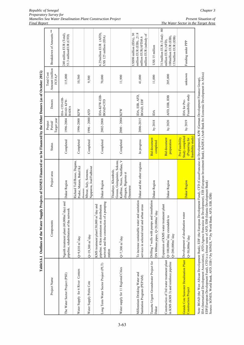
Republic of Senegal Chapter 3 Preparatory Survey for Mamelles Sea Water Desalination Plant Construction Project Present Situation of Final Report The Water Sector in the Target Area
Proj
ect N
ame
Com
pone
nts
Proj
ect a
rea
Stat
usPr
ojec
tPe
riod/
Targ
et y
ear
Don
ors
Tota
l Cos
tA
mou
nt (m
illio
nFC
FA)*
Bre
akdo
wn
of A
mou
nts *
*
The
Wat
er S
ecto
r Pro
ject
(PSE
)N
gnith
trea
tmen
t pla
nt (6
0,00
0m3 /d
ay) a
ndpi
pelin
e, re
habi
litat
ion
of th
e ne
twor
kD
akar
Reg
ion
Com
plet
ed19
96-2
004
IDA
- CFD
-EIB
-B
OA
D- K
FW-
BA
DEA
115,
000
240
mill
ion
EUR
(Tot
al),
53.3
mill
ionE
UR
(CFD
)
Wat
er S
uppl
y fo
r 6 R
iver
Cen
ters
Q=9
,810
m3 /d
ayR
icha
rd T
oll/R
osso
, Dag
ana,
Podo
r, M
atam
, Bak
el K
édo
ugou
Com
plet
ed19
96-2
000
KFW
10,5
60
Wat
er S
uppl
y Pe
tite
Cot
eQ
=19,
300
m3 /d
ayM
bour
, Sal
y, S
omon
e,N
gapa
rou,
Joal
/Fad
hiou
tC
ompl
eted
1996
- 20
00A
FD9,
500
Long
Ter
m W
ater
Sec
tor P
roje
ct (P
LT)
KM
S tre
atm
ent p
lant
130,
000
m3 /d
ay a
ndpi
pelin
e. 4
1km
ext
ensi
on o
n di
strib
utio
nne
twor
k an
d th
e co
nstru
ctio
n of
a p
umpi
ngst
atio
n
Dak
ar R
egio
nC
ompl
eted
2002
-200
8ID
A-K
FW-E
IB-
BO
AD
-CFD
70,0
006.
25m
illio
n EU
R (
AFD
),U
S$ 1
25 m
illio
n (I
DA
)
Wat
er su
pply
for 1
1 R
egio
nal C
ities
Q=7
,300
m3 /d
ay
Thia
diay
e, K
hom
bole
,G
ossa
s, G
uing
uiné
o, S
okon
e,K
affri
ne, N
ioro
, Ndo
ffane
, Vél
inga
ra, B
igno
na e
tO
usso
uye
Com
plet
ed20
00 -
2004
KFW
11,9
00
Mill
enni
um D
rinki
ng W
ater
and
Sani
tatio
n Pr
ogra
m (P
EPA
M)
To in
crea
se su
stai
nabl
e w
ater
and
sani
tatio
nse
rvic
es in
sele
cted
rura
l and
urb
an a
reas
Dak
ar a
nd th
e ot
her r
egio
nsIn
pro
gres
s20
06-2
015
IDA
, EIB
, AFD
,B
OA
D, E
DF
41,0
00
US$
90 m
illio
n (I
DA
), 30
mill
ion
EUR
(EIB
), ,2
1.8
mill
ion
EUR
(AFD
)8.6
mill
ion
EUR
(sub
sidy
of
Ta
sset
te U
rgen
t Gro
undw
ater
Pro
ject
for
Dak
arD
rillin
g 7
wel
ls w
ith p
umps
and
inst
alla
tion
DN
800
mm
pip
es, Q
=20,
000m
3 /day
Dak
ar R
egio
nB
id d
ocum
ent
com
plet
edby
201
8ID
A11
,000
US$
15
mill
ion
Con
stru
ctio
n of
3rd
wat
er tr
eatm
ent p
lant
in K
MS
(KM
S 3)
and
rein
forc
e pi
pelin
e
Expa
nsio
n of
KM
S w
ater
trea
tmen
t pla
ntQ
=100
,000
m3 /d
ay e
xten
dabl
e to
Q=2
00,0
00m
3 /day
Dak
ar R
egio
nB
id d
ocum
ent
prep
arat
ion
by 2
020
AFD
, EIB
, ID
B20
5,00
0
313m
illio
n EU
R (T
otal
) : 8
0m
illio
n EU
R (A
FD),
100m
illio
n EU
R (E
IB),
133m
illio
n EU
R (I
DB
)
Gra
nde
Cot
e Se
awat
er D
esal
inat
ion
Plan
tC
onst
ruct
ion
Proj
ect
Dev
elop
men
t of d
esal
inat
ion
wat
erQ
=50,
000m
3 /day
Dak
ar R
egio
n
Pre-
Feas
ibili
tySt
udy
com
plet
ed(P
repa
ring
for
feas
ibili
ty st
udy)
by 2
019
IDA
for P
re-
Feas
ibili
ty st
udy
unkn
own
Fund
ing
unde
r PPP
Not
e: B
OA
D (t
he W
est A
frica
n D
evel
opm
ent B
ank)
, ED
F (th
e Eu
rope
an D
evel
opm
ent F
und)
, CFD
(Cai
sseF
ranc
aise
de
Dev
elop
men
t), K
fW (G
erm
an D
evel
opm
ent F
inan
ce G
roup
), ID
A (I
nter
natio
nal D
evel
opm
ent A
ssoc
iatio
n),
AFD
(Age
nce
franc
asis
e de
Dev
elop
men
t), E
IB (E
urop
ean
Inve
stm
ent B
ank)
, BA
DEA
(Ara
b B
ank
fro E
cono
mic
Dev
elop
men
t in
Afri
ca)
EDF(
Euro
pean
Dev
elop
men
t Fun
d), C
FD is
a fo
rmer
nam
e of
AFD
, ID
B (I
slam
ic D
evel
opm
ent B
ank)
Sour
ce: S
ON
ES, W
orld
Ban
k, A
FD, E
IB (*
;by
SON
ES, *
*;by
Wor
ld B
ank,
AFD
, EIB
, ID
B)
Tab
le3.
6.1
Out
lines
of t
he W
ater
Sup
ply
Proj
ects
of S
ON
ES
Fina
nced
or
to b
e Fi
nanc
ed b
y th
e O
ther
Don
ors (
as o
f Oct
ober
201
5)
3-63
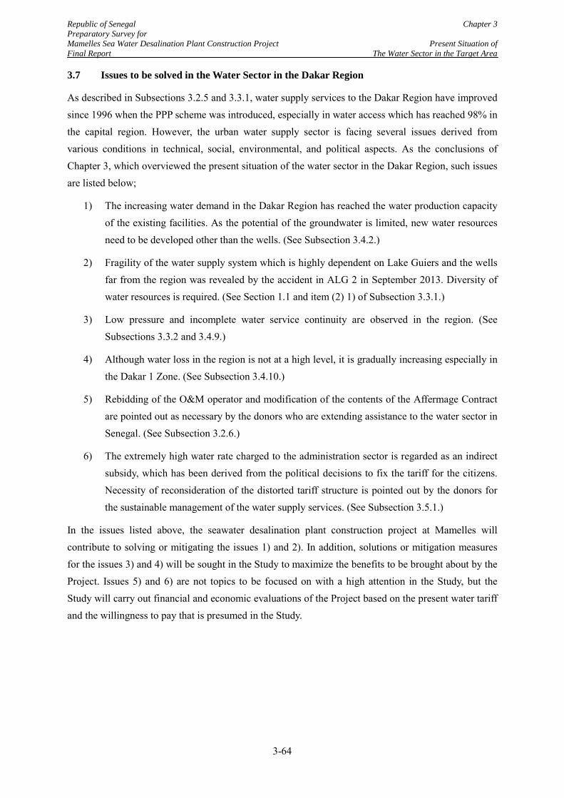
Republic of Senegal Chapter 3 Preparatory Survey for Mamelles Sea Water Desalination Plant Construction Project Present Situation of Final Report The Water Sector in the Target Area
3.7 Issues to be solved in the Water Sector in the Dakar Region
As described in Subsections 3.2.5 and 3.3.1, water supply services to the Dakar Region have improved since 1996 when the PPP scheme was introduced, especially in water access which has reached 98% in the capital region. However, the urban water supply sector is facing several issues derived from various conditions in technical, social, environmental, and political aspects. As the conclusions of Chapter 3, which overviewed the present situation of the water sector in the Dakar Region, such issues are listed below;
1) The increasing water demand in the Dakar Region has reached the water production capacity of the existing facilities. As the potential of the groundwater is limited, new water resources need to be developed other than the wells. (See Subsection 3.4.2.)
2) Fragility of the water supply system which is highly dependent on Lake Guiers and the wells far from the region was revealed by the accident in ALG 2 in September 2013. Diversity of water resources is required. (See Section 1.1 and item (2) 1) of Subsection 3.3.1.)
3) Low pressure and incomplete water service continuity are observed in the region. (See Subsections 3.3.2 and 3.4.9.)
4) Although water loss in the region is not at a high level, it is gradually increasing especially in the Dakar 1 Zone. (See Subsection 3.4.10.)
5) Rebidding of the O&M operator and modification of the contents of the Affermage Contract are pointed out as necessary by the donors who are extending assistance to the water sector in Senegal. (See Subsection 3.2.6.)
6) The extremely high water rate charged to the administration sector is regarded as an indirect subsidy, which has been derived from the political decisions to fix the tariff for the citizens. Necessity of reconsideration of the distorted tariff structure is pointed out by the donors for the sustainable management of the water supply services. (See Subsection 3.5.1.)
In the issues listed above, the seawater desalination plant construction project at Mamelles will contribute to solving or mitigating the issues 1) and 2). In addition, solutions or mitigation measures for the issues 3) and 4) will be sought in the Study to maximize the benefits to be brought about by the Project. Issues 5) and 6) are not topics to be focused on with a high attention in the Study, but the Study will carry out financial and economic evaluations of the Project based on the present water tariff and the willingness to pay that is presumed in the Study.
3-64
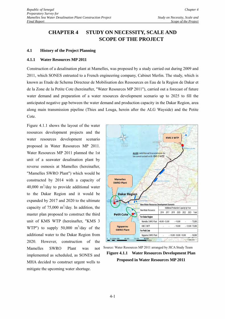
Republic of Senegal Chapter 4 Preparatory Survey for Mamelles Sea Water Desalination Plant Construction Project Study on Necessity, Scale and Final Report Scope of the Project
CHAPTER 4 STUDY ON NECESSITY, SCALE AND SCOPE OF THE PROJECT
4.1 History of the Project Planning
4.1.1 Water Resources MP 2011
Construction of a desalination plant at Mamelles, was proposed by a study carried out during 2009 and 2011, which SONES entrusted to a French engineering company, Cabinet Merlin. The study, which is known as Etude de Schema Directeur de Mobilisation des Ressources en Eau de la Region de Dakar et de la Zone de la Petite Cote (hereinafter, "Water Resources MP 2011"), carried out a forecast of future water demand and preparation of a water resources development scenario up to 2025 to fill the anticipated negative gap between the water demand and production capacity in the Dakar Region, area along main transmission pipeline (Thies and Louga, herein after the ALG Wayside) and the Petite Cote.
Figure 4.1.1 shows the layout of the water resources development projects and the water resources development scenario proposed in Water Resources MP 2011. Water Resources MP 2011 planned the 1st unit of a seawater desalination plant by reverse osmosis at Mamelles (hereinafter, "Mamelles SWRO Plant") which would be constructed by 2014 with a capacity of 40,000 m3/day to provide additional water to the Dakar Region and it would be expanded by 2017 and 2020 to the ultimate capacity of 75,000 m3/day. In addition, the master plan proposed to construct the third unit of KMS WTP (hereinafter, "KMS 3 WTP") to supply 50,000 m3/day of the additional water to the Dakar Region from 2020. However, construction of the Mamelles SWRO Plant was not implemented as scheduled, as SONES and MHA decided to construct urgent wells to mitigate the upcoming water shortage.
New Water Resources Development Scenario
2014 2017 2019 2020 2022 2023 Total
For Dakar Region
Mamelles SWRO Plant +40,000 +25,000 - +10,000 - - 75,000
KMS 3 WTP - - - +50,000 - +25,000 75,000
For Petit Cote
Ngaparou SWRO Plant - - +10,000 +30,000 +10,000 - 50,000
Additional Production Capacity by YearNew Water Resources
Source: Water Resources MP 2011 arranged by JICA Study Team
Figure 4.1.1 Water Resources Development Plan Proposed in Water Resources MP 2011
New Water Resources Development Scenario
2014 2017 2019 2020 2022 2023 Total
For Dakar Region
Mamelles SWRO Plant +40,000 +25,000 - +10,000 - - 75,000
KMS 3 WTP - - - +50,000 - +25,000 75,000
For Petit Cote
Ngaparou SWRO Plant - - +10,000 +30,000 +10,000 - 50,000
Additional Production Capacity by YearNew Water Resources
4-1
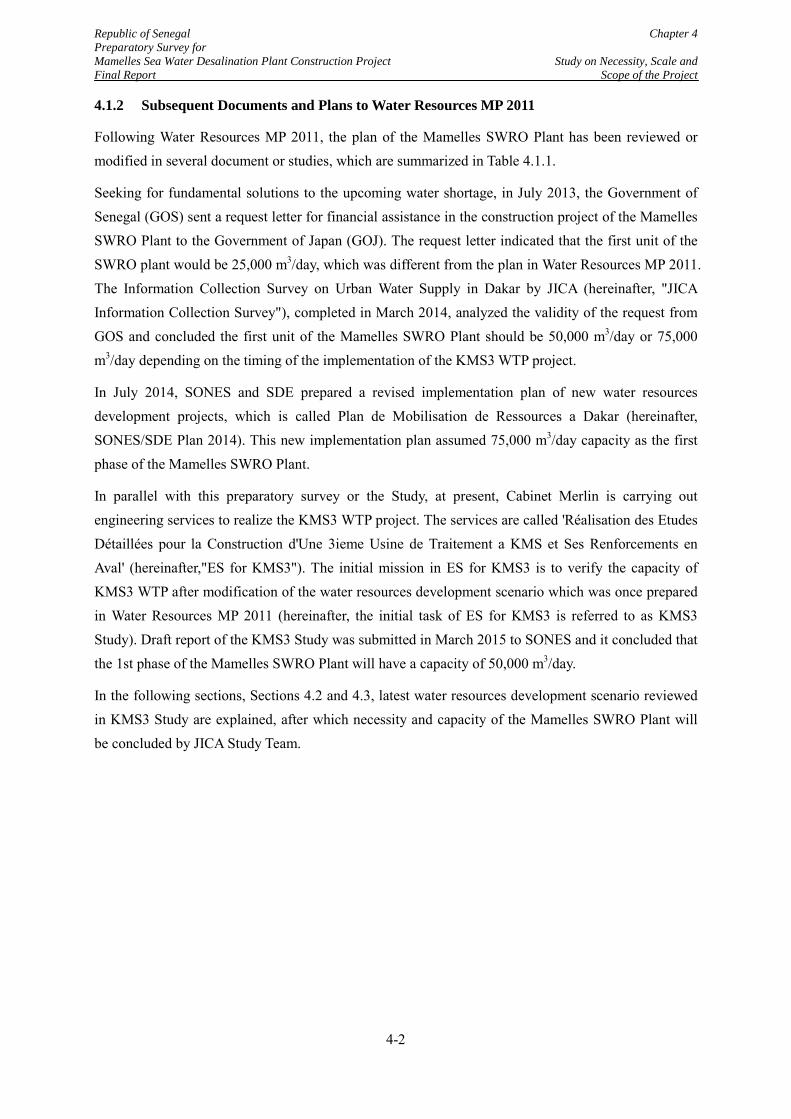
Republic of Senegal Chapter 4 Preparatory Survey for Mamelles Sea Water Desalination Plant Construction Project Study on Necessity, Scale and Final Report Scope of the Project
4.1.2 Subsequent Documents and Plans to Water Resources MP 2011
Following Water Resources MP 2011, the plan of the Mamelles SWRO Plant has been reviewed or modified in several document or studies, which are summarized in Table 4.1.1.
Seeking for fundamental solutions to the upcoming water shortage, in July 2013, the Government of Senegal (GOS) sent a request letter for financial assistance in the construction project of the Mamelles SWRO Plant to the Government of Japan (GOJ). The request letter indicated that the first unit of the SWRO plant would be 25,000 m3/day, which was different from the plan in Water Resources MP 2011. The Information Collection Survey on Urban Water Supply in Dakar by JICA (hereinafter, "JICA Information Collection Survey"), completed in March 2014, analyzed the validity of the request from GOS and concluded the first unit of the Mamelles SWRO Plant should be 50,000 m3/day or 75,000 m3/day depending on the timing of the implementation of the KMS3 WTP project.
In July 2014, SONES and SDE prepared a revised implementation plan of new water resources development projects, which is called Plan de Mobilisation de Ressources a Dakar (hereinafter, SONES/SDE Plan 2014). This new implementation plan assumed 75,000 m3/day capacity as the first phase of the Mamelles SWRO Plant.
In parallel with this preparatory survey or the Study, at present, Cabinet Merlin is carrying out engineering services to realize the KMS3 WTP project. The services are called 'Réalisation des Etudes Détaillées pour la Construction d'Une 3ieme Usine de Traitement a KMS et Ses Renforcements en Aval' (hereinafter,"ES for KMS3"). The initial mission in ES for KMS3 is to verify the capacity of KMS3 WTP after modification of the water resources development scenario which was once prepared in Water Resources MP 2011 (hereinafter, the initial task of ES for KMS3 is referred to as KMS3 Study). Draft report of the KMS3 Study was submitted in March 2015 to SONES and it concluded that the 1st phase of the Mamelles SWRO Plant will have a capacity of 50,000 m3/day.
In the following sections, Sections 4.2 and 4.3, latest water resources development scenario reviewed in KMS3 Study are explained, after which necessity and capacity of the Mamelles SWRO Plant will be concluded by JICA Study Team.
4-2
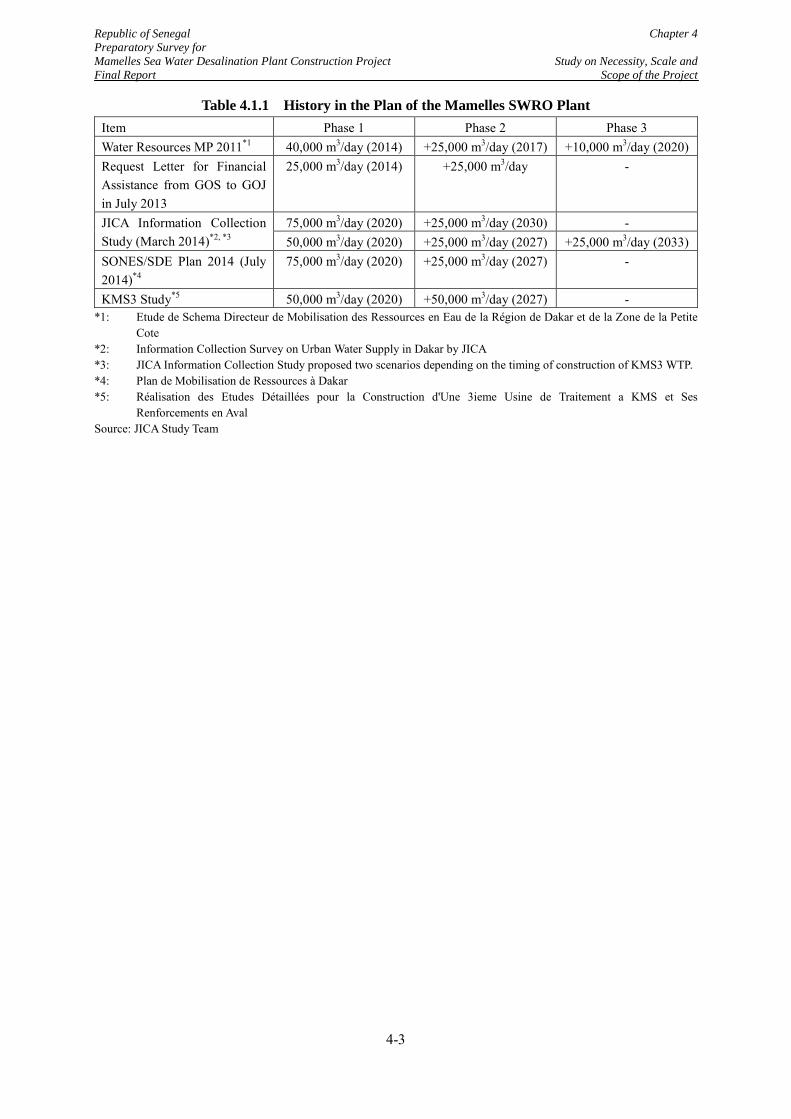
Republic of Senegal Chapter 4 Preparatory Survey for Mamelles Sea Water Desalination Plant Construction Project Study on Necessity, Scale and Final Report Scope of the Project
Table 4.1.1 History in the Plan of the Mamelles SWRO Plant Item Phase 1 Phase 2 Phase 3 Water Resources MP 2011*1 40,000 m3/day (2014) +25,000 m3/day (2017) +10,000 m3/day (2020) Request Letter for Financial Assistance from GOS to GOJ in July 2013
25,000 m3/day (2014) +25,000 m3/day -
JICA Information Collection Study (March 2014)*2, *3
75,000 m3/day (2020) +25,000 m3/day (2030) - 50,000 m3/day (2020) +25,000 m3/day (2027) +25,000 m3/day (2033)
SONES/SDE Plan 2014 (July 2014)*4
75,000 m3/day (2020) +25,000 m3/day (2027) -
KMS3 Study*5 50,000 m3/day (2020) +50,000 m3/day (2027) - *1: Etude de Schema Directeur de Mobilisation des Ressources en Eau de la Région de Dakar et de la Zone de la Petite
Cote *2: Information Collection Survey on Urban Water Supply in Dakar by JICA *3: JICA Information Collection Study proposed two scenarios depending on the timing of construction of KMS3 WTP. *4: Plan de Mobilisation de Ressources à Dakar *5: Réalisation des Etudes Détaillées pour la Construction d'Une 3ieme Usine de Traitement a KMS et Ses
Renforcements en Aval Source: JICA Study Team
4-3
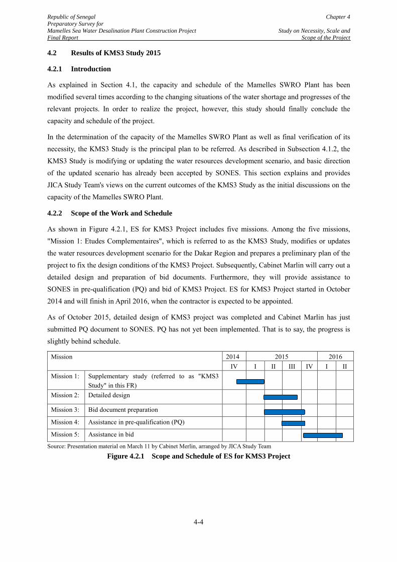
Republic of Senegal Chapter 4 Preparatory Survey for Mamelles Sea Water Desalination Plant Construction Project Study on Necessity, Scale and Final Report Scope of the Project
4.2 Results of KMS3 Study 2015
4.2.1 Introduction
As explained in Section 4.1, the capacity and schedule of the Mamelles SWRO Plant has been modified several times according to the changing situations of the water shortage and progresses of the relevant projects. In order to realize the project, however, this study should finally conclude the capacity and schedule of the project.
In the determination of the capacity of the Mamelles SWRO Plant as well as final verification of its necessity, the KMS3 Study is the principal plan to be referred. As described in Subsection 4.1.2, the KMS3 Study is modifying or updating the water resources development scenario, and basic direction of the updated scenario has already been accepted by SONES. This section explains and provides JICA Study Team's views on the current outcomes of the KMS3 Study as the initial discussions on the capacity of the Mamelles SWRO Plant.
4.2.2 Scope of the Work and Schedule
As shown in Figure 4.2.1, ES for KMS3 Project includes five missions. Among the five missions, "Mission 1: Etudes Complementaires", which is referred to as the KMS3 Study, modifies or updates the water resources development scenario for the Dakar Region and prepares a preliminary plan of the project to fix the design conditions of the KMS3 Project. Subsequently, Cabinet Marlin will carry out a detailed design and preparation of bid documents. Furthermore, they will provide assistance to SONES in pre-qualification (PQ) and bid of KMS3 Project. ES for KMS3 Project started in October 2014 and will finish in April 2016, when the contractor is expected to be appointed.
As of October 2015, detailed design of KMS3 project was completed and Cabinet Marlin has just submitted PQ document to SONES. PQ has not yet been implemented. That is to say, the progress is slightly behind schedule.
Mission 2014 2015 2016 IV I II III IV I II
Mission 1: Supplementary study (referred to as "KMS3 Study" in this FR)
Mission 2: Detailed design
Mission 3: Bid document preparation
Mission 4: Assistance in pre-qualification (PQ)
Mission 5: Assistance in bid
Source: Presentation material on March 11 by Cabinet Merlin, arranged by JICA Study Team
Figure 4.2.1 Scope and Schedule of ES for KMS3 Project
4-4
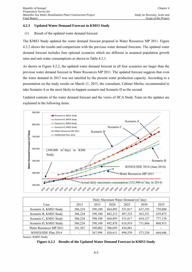
Republic of Senegal Chapter 4 Preparatory Survey for Mamelles Sea Water Desalination Plant Construction Project Study on Necessity, Scale and Final Report Scope of the Project
4.2.3 Updated Water Demand Forecast in KMS3 Study
(1) Result of the updated water demand forecast
The KMS3 Study updated the water demand forecast prepared in Water Resources MP 2011. Figure 4.2.2 shows the results and comparisons with the previous water demand forecasts. The updated water demand forecast includes four optional scenarios which are different in assumed population growth rates and unit water consumptions as shown in Table 4.2.1.
As shown in Figure 4.2.2, the updated water demand forecast in all four scenarios are larger than the previous water demand forecast in Water Resources MP 2011. The updated forecast suggests that even the water demand in 2013 was not satisfied by the present water production capacity. According to a presentation on the study results on March 11, 2015, the consultant, Cabinet Merlin, recommended to take Scenario A as the most likely-to-happen scenario and Scenario D as the second.
Updated contents of the water demand forecast and the views of JICA Study Team on the updates are explained in the following items.
Case Daily Maximum Water Demand (m3/day)
2013 2015 2020 2025 2030 2035 Scenario A, KMS3 Study 386,224 398,180 464,893 551,017 637,193 739,888 Scenario B, KMS3 Study 386,224 398,180 442,213 497,323 563,351 639,475 Scenario C, KMS3 Study 386,224 398,180 464,893 551,017 654,127 777,139 Scenario D, KMS3 Study 386,224 398,180 492,876 616,919 731,866 868,915 Water Resources MP 2011 341,367 349,082 386,695 434,961 - - SONES/SDE Plan 2014 - 367,998 426,611 494,559 573,330 664,646
Source: KMS3 Study
Figure 4.2.2 Results of the Updated Water Demand Forecast in KMS3 Study
300,000
400,000
500,000
600,000
700,000
800,000
900,000
Wat
er D
eman
d Fo
reca
ast (
m3 /
day)
Scenario A, KMS3 Study
Scenario B, KMS3 Study
Scenario C, KMS3 Study
Scenario D, KMS3 Study
Water Resources MP 2011
SONES/SDE Plan 2014
Actual daily maximum consumption (352,900 m3/day in 2014)
Scenario A
Scenario D
Scenario B
Scenario C
Water Resources MP 2011
SONES/SDE 2014 (June 2014)
(349,000 m3/day) in KMS Study
4-5
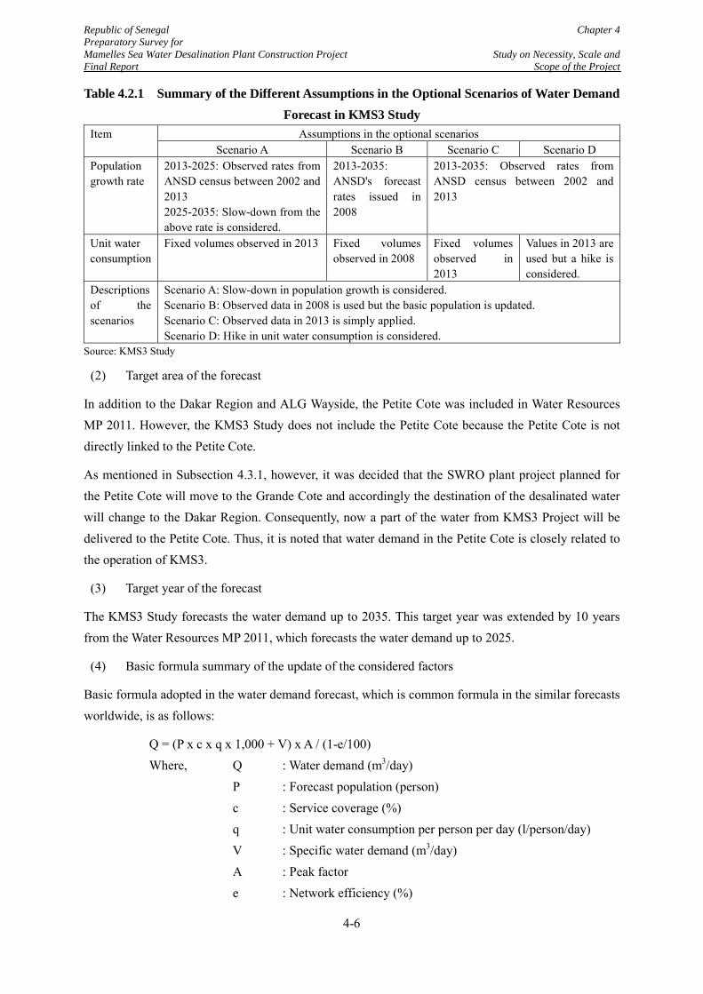
Republic of Senegal Chapter 4 Preparatory Survey for Mamelles Sea Water Desalination Plant Construction Project Study on Necessity, Scale and Final Report Scope of the Project
Table 4.2.1 Summary of the Different Assumptions in the Optional Scenarios of Water Demand Forecast in KMS3 Study
Item Assumptions in the optional scenarios Scenario A Scenario B Scenario C Scenario D
Population growth rate
2013-2025: Observed rates from ANSD census between 2002 and 2013 2025-2035: Slow-down from the above rate is considered.
2013-2035: ANSD's forecast rates issued in 2008
2013-2035: Observed rates from ANSD census between 2002 and 2013
Unit water consumption
Fixed volumes observed in 2013 Fixed volumes observed in 2008
Fixed volumes observed in 2013
Values in 2013 are used but a hike is considered.
Descriptions of the scenarios
Scenario A: Slow-down in population growth is considered. Scenario B: Observed data in 2008 is used but the basic population is updated. Scenario C: Observed data in 2013 is simply applied. Scenario D: Hike in unit water consumption is considered.
Source: KMS3 Study
(2) Target area of the forecast
In addition to the Dakar Region and ALG Wayside, the Petite Cote was included in Water Resources MP 2011. However, the KMS3 Study does not include the Petite Cote because the Petite Cote is not directly linked to the Petite Cote.
As mentioned in Subsection 4.3.1, however, it was decided that the SWRO plant project planned for the Petite Cote will move to the Grande Cote and accordingly the destination of the desalinated water will change to the Dakar Region. Consequently, now a part of the water from KMS3 Project will be delivered to the Petite Cote. Thus, it is noted that water demand in the Petite Cote is closely related to the operation of KMS3.
(3) Target year of the forecast
The KMS3 Study forecasts the water demand up to 2035. This target year was extended by 10 years from the Water Resources MP 2011, which forecasts the water demand up to 2025.
(4) Basic formula summary of the update of the considered factors
Basic formula adopted in the water demand forecast, which is common formula in the similar forecasts worldwide, is as follows:
Q = (P x c x q x 1,000 + V) x A / (1-e/100) Where, Q : Water demand (m3/day) P : Forecast population (person) c : Service coverage (%) q : Unit water consumption per person per day (l/person/day) V : Specific water demand (m3/day) A : Peak factor e : Network efficiency (%)
4-6
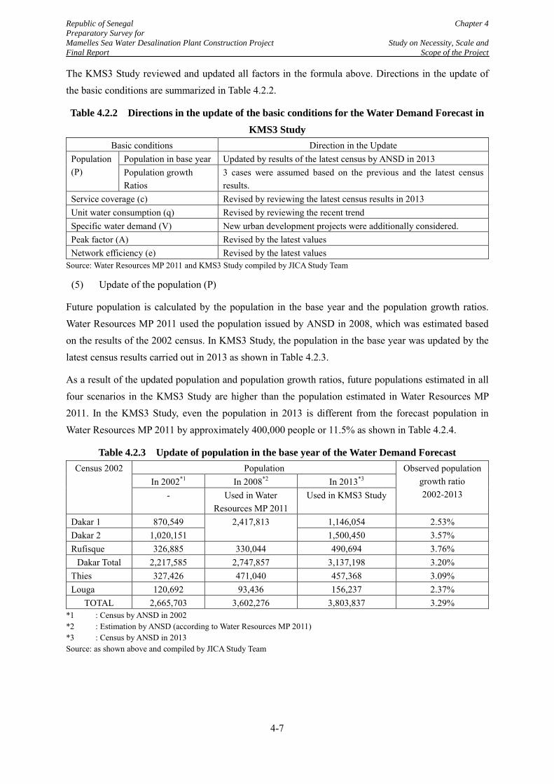
Republic of Senegal Chapter 4 Preparatory Survey for Mamelles Sea Water Desalination Plant Construction Project Study on Necessity, Scale and Final Report Scope of the Project
The KMS3 Study reviewed and updated all factors in the formula above. Directions in the update of the basic conditions are summarized in Table 4.2.2.
Table 4.2.2 Directions in the update of the basic conditions for the Water Demand Forecast in KMS3 Study
Basic conditions Direction in the Update Population (P)
Population in base year Updated by results of the latest census by ANSD in 2013 Population growth Ratios
3 cases were assumed based on the previous and the latest census results.
Service coverage (c) Revised by reviewing the latest census results in 2013 Unit water consumption (q) Revised by reviewing the recent trend Specific water demand (V) New urban development projects were additionally considered. Peak factor (A) Revised by the latest values Network efficiency (e) Revised by the latest values
Source: Water Resources MP 2011 and KMS3 Study compiled by JICA Study Team
(5) Update of the population (P)
Future population is calculated by the population in the base year and the population growth ratios. Water Resources MP 2011 used the population issued by ANSD in 2008, which was estimated based on the results of the 2002 census. In KMS3 Study, the population in the base year was updated by the latest census results carried out in 2013 as shown in Table 4.2.3.
As a result of the updated population and population growth ratios, future populations estimated in all four scenarios in the KMS3 Study are higher than the population estimated in Water Resources MP 2011. In the KMS3 Study, even the population in 2013 is different from the forecast population in Water Resources MP 2011 by approximately 400,000 people or 11.5% as shown in Table 4.2.4.
Table 4.2.3 Update of population in the base year of the Water Demand Forecast Census 2002 Population Observed population
growth ratio 2002-2013
In 2002*1 In 2008*2 In 2013*3 - Used in Water
Resources MP 2011 Used in KMS3 Study
Dakar 1 870,549 2,417,813 1,146,054 2.53% Dakar 2 1,020,151 1,500,450 3.57% Rufisque 326,885 330,044 490,694 3.76%
Dakar Total 2,217,585 2,747,857 3,137,198 3.20% Thies 327,426 471,040 457,368 3.09% Louga 120,692 93,436 156,237 2.37%
TOTAL 2,665,703 3,602,276 3,803,837 3.29% *1 : Census by ANSD in 2002 *2 : Estimation by ANSD (according to Water Resources MP 2011) *3 : Census by ANSD in 2013 Source: as shown above and compiled by JICA Study Team
4-7
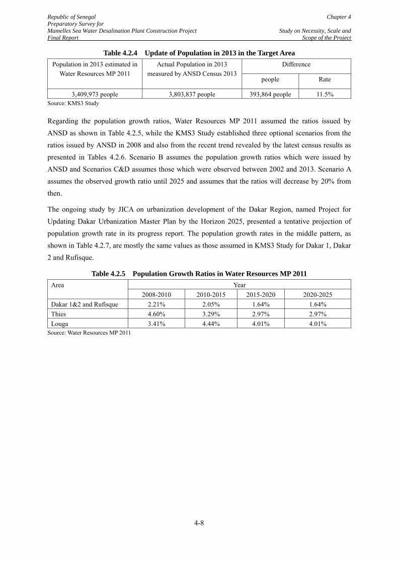
Republic of Senegal Chapter 4 Preparatory Survey for Mamelles Sea Water Desalination Plant Construction Project Study on Necessity, Scale and Final Report Scope of the Project
Table 4.2.4 Update of Population in 2013 in the Target Area Population in 2013 estimated in
Water Resources MP 2011 Actual Population in 2013
measured by ANSD Census 2013 Difference
people Rate
3,409,973 people 3,803,837 people 393,864 people 11.5% Source: KMS3 Study
Regarding the population growth ratios, Water Resources MP 2011 assumed the ratios issued by ANSD as shown in Table 4.2.5, while the KMS3 Study established three optional scenarios from the ratios issued by ANSD in 2008 and also from the recent trend revealed by the latest census results as presented in Tables 4.2.6. Scenario B assumes the population growth ratios which were issued by ANSD and Scenarios C&D assumes those which were observed between 2002 and 2013. Scenario A assumes the observed growth ratio until 2025 and assumes that the ratios will decrease by 20% from then.
The ongoing study by JICA on urbanization development of the Dakar Region, named Project for Updating Dakar Urbanization Master Plan by the Horizon 2025, presented a tentative projection of population growth rate in its progress report. The population growth rates in the middle pattern, as shown in Table 4.2.7, are mostly the same values as those assumed in KMS3 Study for Dakar 1, Dakar 2 and Rufisque.
Table 4.2.5 Population Growth Ratios in Water Resources MP 2011 Area Year
2008-2010 2010-2015 2015-2020 2020-2025 Dakar 1&2 and Rufisque 2.21% 2.05% 1.64% 1.64% Thies 4.60% 3.29% 2.97% 2.97% Louga 3.41% 4.44% 4.01% 4.01%
Source: Water Resources MP 2011
4-8
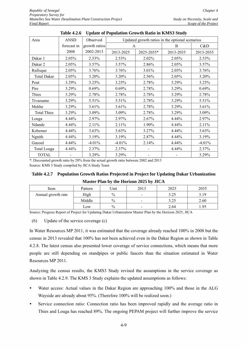
Republic of Senegal Chapter 4 Preparatory Survey for Mamelles Sea Water Desalination Plant Construction Project Study on Necessity, Scale and Final Report Scope of the Project
Table 4.2.6 Update of Population Growth Ratio in KMS3 Study Area ANSD
forecast in 2008
Observed growth ratios 2002-2013
Updated growth ratios in the optional scenarios A B C&D
2013-2025 2025-2035* 2013-2035 2013-2035 Dakar 1 2.05% 2.53% 2.53% 2.02% 2.05% 2.53% Dakar 2 2.05% 3.57% 3.57% 2.86% 2.05% 3.57% Rufisque 2.05% 3.76% 3.76% 3.01% 2.05% 3.76%
Total Dakar 2.05% 3.20% 3.20% 2.56% 2.05% 3.20% Pout 3.29% 3.25% 3.25% 2.78% 3.29% 3.25% Pire 3.29% 0.69% 0.69% 2.78% 3.29% 0.69% Thies 3.29% 2.78% 2.78% 2.78% 3.29% 2.78% Tivaouane 3.29% 5.51% 5.51% 2.78% 3.29% 5.51% Mekhe 3.29% 3.61% 3.61% 2.78% 3.29% 3.61%
Total Thies 3.29% 3.09% 3.09% 2.78% 3.29% 3.09% Louga 4.44% 2.97% 2.97% 2.67% 4.44% 2.97% Ndande 4.44% 2.11% 2.11% 1.90% 4.44% 2.11% Kebemer 4.44% 3.63% 3.63% 3.27% 4.44% 3.63% Ngnith 4.44% 3.19% 3.19% 2.87% 4.44% 3.19% Gueoul 4.44% -4.01% -4.01% 2.14% 4.44% -4.01%
Total Louga 4.44% 2.37% 2.37% - 4.44% 2.37% TOTAL - 3.29% 3.29% - - 3.29%
*: Discounted growth ratio by 20% from the actual growth ratio between 2002 and 2013 Source: KMS 3 Study compiled by JICA Study Team
Table 4.2.7 Population Growth Ratios Projected in Project for Updating Dakar Urbanization Master Plan by the Horizon 2025 by JICA
Item Pattern Unit 2013 2025 2035 Annual growth rate High % - 3.25 3.19
Middle % - 3.25 2.60 Low % - 2.64 1.95
Source: Progress Report of Project for Updating Dakar Urbanization Master Plan by the Horizon 2025, JICA
(6) Update of the service coverage (c)
In Water Resources MP 2011, it was estimated that the coverage already reached 100% in 2008 but the census in 2013 revealed that 100% has not been achieved even in the Dakar Region as shown in Table 4.2.8. The latest census also presented lower coverage of service connections, which means that more people are still depending on standpipes or public faucets than the situation estimated in Water Resources MP 2011.
Analyzing the census results, the KMS3 Study revised the assumptions in the service coverage as shown in Table 4.2.9. The KMS 3 Study explains the updated assumptions as follows:
Water access: Actual values in the Dakar Region are approaching 100% and those in the ALG Wayside are already about 95%. (Therefore 100% will be realized soon.)
Service connection ratio: Connection ratio has been improved rapidly and the average ratio in Thies and Louga has reached 89%. The ongoing PEPAM project will further improve the service
4-9
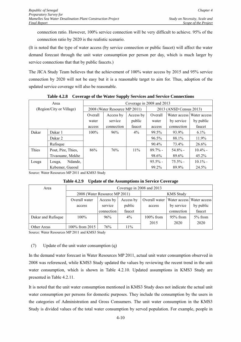
Republic of Senegal Chapter 4 Preparatory Survey for Mamelles Sea Water Desalination Plant Construction Project Study on Necessity, Scale and Final Report Scope of the Project
connection ratio. However, 100% service connection will be very difficult to achieve. 95% of the connection ratio by 2020 is the realistic scenario.
(It is noted that the type of water access (by service connection or public faucet) will affect the water demand forecast through the unit water consumption per person per day, which is much larger by service connections that that by public faucets.)
The JICA Study Team believes that the achievement of 100% water access by 2015 and 95% service connection by 2020 will not be easy but it is a reasonable target to aim for. Thus, adoption of the updated service coverage will also be reasonable.
Table 4.2.8 Coverage of the Water Supply Services and Service Connections Area
(Region/City or Village) Coverage in 2008 and 2013
2008 (Water Resource MP 2011) 2013 (ANSD Census 2013) Overall water access
Access by service
connection
Access by public faucet
Overall water access
Water access by service connection
Water access by public
faucet Dakar Dakar 1 100% 96% 4% 99.5% 93.9% 6.1%
Dakar 2 96.5% 88.1% 11.9% Rufisque 90.4% 73.4% 26.6%
Thies Pout, Pire, Thies, Tivaouane, Mekhe
86% 76% 11% 89.7% - 98.6%
54.8% - 89.6%
10.4% - 45.2%
Louga Louga, Ndande, Kebemer, Gueoul
95.5% - 99.2%
75.5% - 89.9%
10.1% - 24.5%
Source: Water Resources MP 2011 and KMS3 Study
Table 4.2.9 Update of the Assumptions in Service Coverage Area Coverage in 2008 and 2013
2008 (Water Resource MP 2011) KMS Study Overall water
access Access by
service connection
Access by public faucet
Overall water access
Water access by service connection
Water access by public
faucet Dakar and Rufisque 100% 96% 4% 100% from
2015 95% from
2020 5% from
2020 Other Areas 100% from 2015 76% 11%
Source: Water Resources MP 2011 and KMS3 Study
(7) Update of the unit water consumption (q)
In the demand water forecast in Water Resources MP 2011, actual unit water consumption observed in 2008 was referenced, while KMS3 Study updated the values by reviewing the recent trend in the unit water consumption, which is shown in Table 4.2.10. Updated assumptions in KMS3 Study are presented in Table 4.2.11.
It is noted that the unit water consumption mentioned in KMS3 Study does not indicate the actual unit water consumption per persons for domestic purposes. They include the consumption by the users in the categories of Administration and Gross Consumers. The unit water consumption in the KMS3 Study is divided values of the total water consumption by served population. For example, people in
4-10
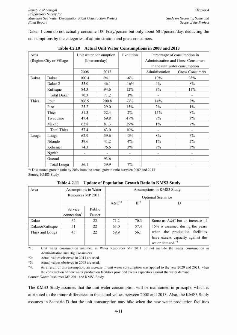
Republic of Senegal Chapter 4 Preparatory Survey for Mamelles Sea Water Desalination Plant Construction Project Study on Necessity, Scale and Final Report Scope of the Project
Dakar 1 zone do not actually consume 100 l/day/person but only about 60 l/person/day, deducting the consumptions by the categories of administration and grass consumers.
Table 4.2.10 Actual Unit Water Consumptions in 2008 and 2013 Area (Region/City or Village
Unit water consumption (l/person/day)
Evolution Percentage of consumption in Administration and Gross Consumers
in the unit water consumption 2008 2013 Administration Gross Consumers
Dakar Dakar 1 100.4 94.1 -6% 10% 28% Dakar 2 55.0 46.1 -16% 4% 8% Rufisque 84.3 94.6 12% 3% 11%
Total Dakar 70.3 71.2 1% - - Thies Pout 206.9 200.8 -3% 14% 2%
Pire 25.2 29.0 15% 2% 1% Thies 51.3 52.4 2% 15% 8% Tivaouane 47.4 69.8 47% 7% 3% Mekhe 62.8 81.3 29% 1% 7%
Total Thies 57.4 63.0 10% - - Louga Louga 62.9 59.6 -5% 8% 6%
Ndande 39.6 41.2 4% 1% 2% Kebemer 74.3 76.6 3% 8% 3% Ngnith - - - - - Gueoul - 93.6 - - -
Total Louga 56.1 59.9 7% - - *: Discounted growth ratio by 20% from the actual growth ratio between 2002 and 2013 Source: KMS3 Study
Table 4.2.11 Update of Population Growth Ratio in KMS3 Study Area Assumptions in Water
Resources MP 2011 Assumptions in KMS3 Study
Optional Scenarios A&C*2 B*3 D
Service connection*1
Public Faucet
Dakar 62 22 71.2 70.3 Same as A&C but an increase of 15% is assumed during the years when the production facilities have excess capacity against the water demand.*4
Dakar&Rufisque 51 22 63.0 57.4 Thies and Louga 45 22 59.9 56.1
*1: Unit water consumption assumed in Water Resources MP 2011 do not include the water consumption in Administration and Big Consumers
*2: Actual values observed in 2013 are used. *3: Actual values observed in 2008 are used. *4: As a result of this assumption, an increase in unit water consumption was applied to the year 2020 and 2021, when
the construction of new water production facilities provided excess capacities against the water demand. Source: Water Resources MP 2011 and KMS3 Study
The KMS3 Study assumes that the unit water consumption will be maintained in principle, which is attributed to the minor differences in the actual values between 2008 and 2013. Also, the KMS3 Study assumes in Scenario D that the unit consumption may hike when the new water production facilities
4-11
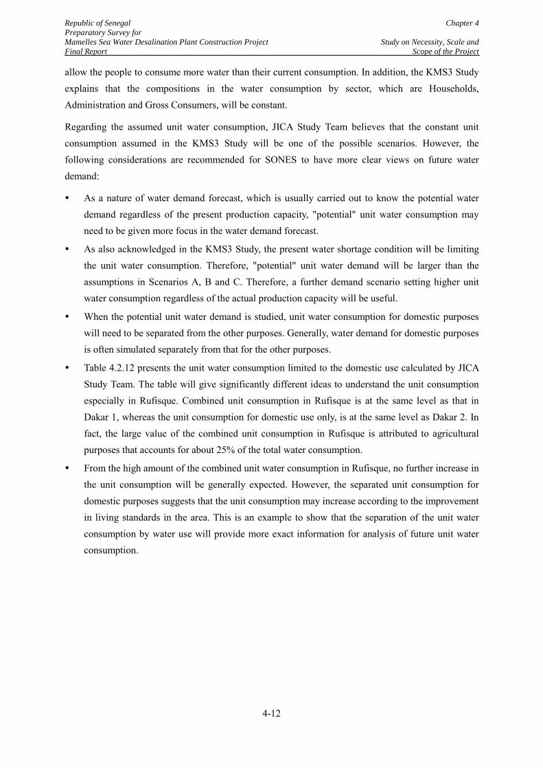
Republic of Senegal Chapter 4 Preparatory Survey for Mamelles Sea Water Desalination Plant Construction Project Study on Necessity, Scale and Final Report Scope of the Project
allow the people to consume more water than their current consumption. In addition, the KMS3 Study explains that the compositions in the water consumption by sector, which are Households, Administration and Gross Consumers, will be constant.
Regarding the assumed unit water consumption, JICA Study Team believes that the constant unit consumption assumed in the KMS3 Study will be one of the possible scenarios. However, the following considerations are recommended for SONES to have more clear views on future water demand:
As a nature of water demand forecast, which is usually carried out to know the potential water demand regardless of the present production capacity, "potential" unit water consumption may need to be given more focus in the water demand forecast.
As also acknowledged in the KMS3 Study, the present water shortage condition will be limiting the unit water consumption. Therefore, "potential" unit water demand will be larger than the assumptions in Scenarios A, B and C. Therefore, a further demand scenario setting higher unit water consumption regardless of the actual production capacity will be useful.
When the potential unit water demand is studied, unit water consumption for domestic purposes will need to be separated from the other purposes. Generally, water demand for domestic purposes is often simulated separately from that for the other purposes.
Table 4.2.12 presents the unit water consumption limited to the domestic use calculated by JICA Study Team. The table will give significantly different ideas to understand the unit consumption especially in Rufisque. Combined unit consumption in Rufisque is at the same level as that in Dakar 1, whereas the unit consumption for domestic use only, is at the same level as Dakar 2. In fact, the large value of the combined unit consumption in Rufisque is attributed to agricultural purposes that accounts for about 25% of the total water consumption.
From the high amount of the combined unit water consumption in Rufisque, no further increase in the unit consumption will be generally expected. However, the separated unit consumption for domestic purposes suggests that the unit consumption may increase according to the improvement in living standards in the area. This is an example to show that the separation of the unit water consumption by water use will provide more exact information for analysis of future unit water consumption.
4-12
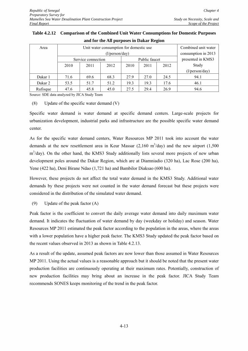
Republic of Senegal Chapter 4 Preparatory Survey for Mamelles Sea Water Desalination Plant Construction Project Study on Necessity, Scale and Final Report Scope of the Project
Table 4.2.12 Comparison of the Combined Unit Water Consumptions for Domestic Purposes and for the All purposes in Dakar Region
Area Unit water consumption for domestic use (l/person/day)
Combined unit water consumption in 2013 presented in KMS3
Study (l/person/day)
Service connection Public faucet 2010 2011 2012 2010 2011 2012
Dakar 1 71.6 69.6 68.3 27.9 27.0 24.5 94.1 Dakar 2 53.5 51.7 51.2 19.3 19.3 17.6 46.1 Rufisque 47.6 45.8 45.0 27.5 29.4 26.9 94.6
Source: SDE data analyzed by JICA Study Team
(8) Update of the specific water demand (V)
Specific water demand is water demand at specific demand centers. Large-scale projects for urbanization development, industrial parks and infrastructure are the possible specific water demand center.
As for the specific water demand centers, Water Resources MP 2011 took into account the water demands at the new resettlement area in Keur Massar (2,160 m3/day) and the new airport (1,500 m3/day). On the other hand, the KMS3 Study additionally lists several more projects of new urban development poles around the Dakar Region, which are at Diamniadio (320 ha), Lac Rose (200 ha), Yene (422 ha), Deni Birane Ndao (1,721 ha) and Bambilor Diaksao (600 ha).
However, these projects do not affect the total water demand in the KMS3 Study. Additional water demands by these projects were not counted in the water demand forecast but these projects were considered in the distribution of the simulated water demand.
(9) Update of the peak factor (A)
Peak factor is the coefficient to convert the daily average water demand into daily maximum water demand. It indicates the fluctuation of water demand by day (weekday or holiday) and season. Water Resources MP 2011 estimated the peak factor according to the population in the areas, where the areas with a lower population have a higher peak factor. The KMS3 Study updated the peak factor based on the recent values observed in 2013 as shown in Table 4.2.13.
As a result of the update, assumed peak factors are now lower than those assumed in Water Resources MP 2011. Using the actual values is a reasonable approach but it should be noted that the present water production facilities are continuously operating at their maximum rates. Potentially, construction of new production facilities may bring about an increase in the peak factor. JICA Study Team recommends SONES keeps monitoring of the trend in the peak factor.
4-13
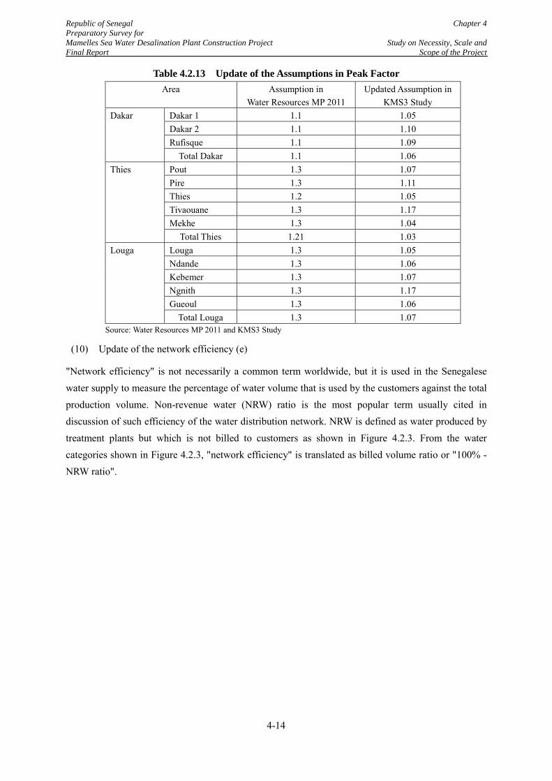
Republic of Senegal Chapter 4 Preparatory Survey for Mamelles Sea Water Desalination Plant Construction Project Study on Necessity, Scale and Final Report Scope of the Project
Table 4.2.13 Update of the Assumptions in Peak Factor Area Assumption in
Water Resources MP 2011 Updated Assumption in
KMS3 Study Dakar Dakar 1 1.1 1.05
Dakar 2 1.1 1.10 Rufisque 1.1 1.09
Total Dakar 1.1 1.06 Thies Pout 1.3 1.07
Pire 1.3 1.11 Thies 1.2 1.05 Tivaouane 1.3 1.17 Mekhe 1.3 1.04
Total Thies 1.21 1.03 Louga Louga 1.3 1.05
Ndande 1.3 1.06 Kebemer 1.3 1.07 Ngnith 1.3 1.17 Gueoul 1.3 1.06
Total Louga 1.3 1.07 Source: Water Resources MP 2011 and KMS3 Study
(10) Update of the network efficiency (e)
"Network efficiency" is not necessarily a common term worldwide, but it is used in the Senegalese water supply to measure the percentage of water volume that is used by the customers against the total production volume. Non-revenue water (NRW) ratio is the most popular term usually cited in discussion of such efficiency of the water distribution network. NRW is defined as water produced by treatment plants but which is not billed to customers as shown in Figure 4.2.3. From the water categories shown in Figure 4.2.3, "network efficiency" is translated as billed volume ratio or "100% - NRW ratio".
4-14
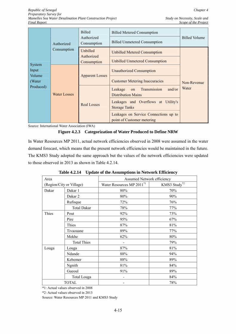
Republic of Senegal Chapter 4 Preparatory Survey for Mamelles Sea Water Desalination Plant Construction Project Study on Necessity, Scale and Final Report Scope of the Project
System Input Volume (Water Produced)
Authorized Consumption
Billed Authorized Consumption
Billed Metered Consumption Billed Volume
Billed Unmetered Consumption
Unbilled Authorized Consumption
Unbilled Metered Consumption
Non-Revenue Water
Unbilled Unmetered Consumption
Water Losses
Apparent Losses Unauthorized Consumption
Customer Metering Inaccuracies
Real Losses
Leakage on Transmission and/or Distribution Mains
Leakages and Overflows at Utility's Storage Tanks
Leakages on Service Connections up to point of Customer metering
Source: International Water Association (IWA)
Figure 4.2.3 Categorization of Water Produced to Define NRW
In Water Resources MP 2011, actual network efficiencies observed in 2008 were assumed in the water demand forecast, which means that the present network efficiencies would be maintained in the future. The KMS3 Study adopted the same approach but the values of the network efficiencies were updated to those observed in 2013 as shown in Table 4.2.14.
Table 4.2.14 Update of the Assumptions in Network Efficiency Area (Region/City or Village)
Assumed Network efficiency Water Resources MP 2011*1 KMS3 Study*2
Dakar Dakar 1 80% 70% Dakar 2 80% 90% Rufisque 72% 76%
Total Dakar 78% 77% Thies Pout 92% 73%
Pire 95% 67% Thies 87% 81% Tivaouane 89% 77% Mekhe 62% 80%
Total Thies - 79% Louga Louga 87% 81%
Ndande 88% 94% Kebemer 88% 89% Ngnith 81% 84% Gueoul 91% 89%
Total Louga - 84% TOTAL - 78%
*1: Actual values observed in 2008 *2: Actual values observed in 2013 Source: Water Resources MP 2011 and KMS3 Study
4-15
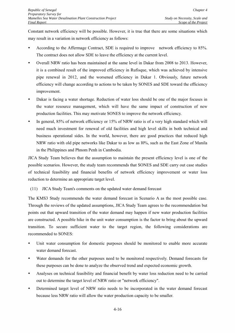
Republic of Senegal Chapter 4 Preparatory Survey for Mamelles Sea Water Desalination Plant Construction Project Study on Necessity, Scale and Final Report Scope of the Project
Constant network efficiency will be possible. However, it is true that there are some situations which may result in a variation in network efficiency as follows:
According to the Affermage Contract, SDE is required to improve network efficiency to 85%. The contract does not allow SDE to leave the efficiency at the current level.
Overall NRW ratio has been maintained at the same level in Dakar from 2008 to 2013. However, it is a combined result of the improved efficiency in Rufisque, which was achieved by intensive pipe renewal in 2012, and the worsened efficiency in Dakar 1. Obviously, future network efficiency will change according to actions to be taken by SONES and SDE toward the efficiency improvement.
Dakar is facing a water shortage. Reduction of water loss should be one of the major focuses in the water resource management, which will have the same impact of construction of new production facilities. This may motivate SONES to improve the network efficiency.
In general, 85% of network efficiency or 15% of NRW ratio is of a very high standard which will need much investment for renewal of old facilities and high level skills in both technical and business operational sides. In the world, however, there are good practices that reduced high NRW ratio with old pipe networks like Dakar to as low as l0%, such as the East Zone of Manila in the Philippines and Phnom Penh in Cambodia.
JICA Study Team believes that the assumption to maintain the present efficiency level is one of the possible scenarios. However, the study team recommends that SONES and SDE carry out case studies of technical feasibility and financial benefits of network efficiency improvement or water loss reduction to determine an appropriate target level.
(11) JICA Study Team's comments on the updated water demand forecast
The KMS3 Study recommends the water demand forecast in Scenario A as the most possible case. Through the reviews of the updated assumptions, JICA Study Team agrees to the recommendation but points out that upward transition of the water demand may happen if new water production facilities are constructed. A possible hike in the unit water consumption is the factor to bring about the upward transition. To secure sufficient water to the target region, the following considerations are recommended to SONES:
Unit water consumption for domestic purposes should be monitored to enable more accurate water demand forecast.
Water demands for the other purposes need to be monitored respectively. Demand forecasts for these purposes can be done to analyze the observed trend and expected economic growth.
Analyses on technical feasibility and financial benefit by water loss reduction need to be carried out to determine the target level of NRW ratio or "network efficiency".
Determined target level of NRW ratio needs to be incorporated in the water demand forecast because less NRW ratio will allow the water production capacity to be smaller.
4-16
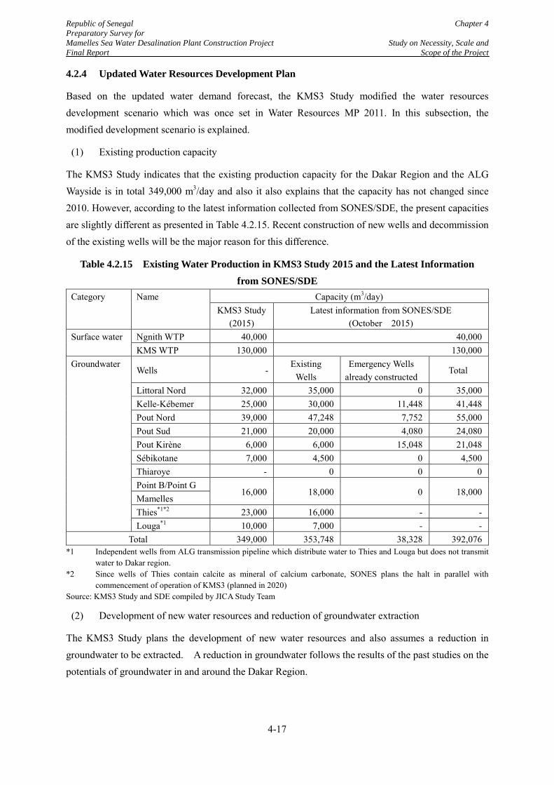
Republic of Senegal Chapter 4 Preparatory Survey for Mamelles Sea Water Desalination Plant Construction Project Study on Necessity, Scale and Final Report Scope of the Project
4.2.4 Updated Water Resources Development Plan
Based on the updated water demand forecast, the KMS3 Study modified the water resources development scenario which was once set in Water Resources MP 2011. In this subsection, the modified development scenario is explained.
(1) Existing production capacity
The KMS3 Study indicates that the existing production capacity for the Dakar Region and the ALG Wayside is in total 349,000 m3/day and also it also explains that the capacity has not changed since 2010. However, according to the latest information collected from SONES/SDE, the present capacities are slightly different as presented in Table 4.2.15. Recent construction of new wells and decommission of the existing wells will be the major reason for this difference.
Table 4.2.15 Existing Water Production in KMS3 Study 2015 and the Latest Information from SONES/SDE
Category Name Capacity (m3/day) KMS3 Study
(2015) Latest information from SONES/SDE
(October 2015) Surface water Ngnith WTP 40,000 40,000
KMS WTP 130,000 130,000 Groundwater
Wells - Existing
Wells Emergency Wells
already constructed Total
Littoral Nord 32,000 35,000 0 35,000 Kelle-Kébemer 25,000 30,000 11,448 41,448 Pout Nord 39,000 47,248 7,752 55,000 Pout Sud 21,000 20,000 4,080 24,080 Pout Kirène 6,000 6,000 15,048 21,048 Sébikotane 7,000 4,500 0 4,500 Thiaroye - 0 0 0 Point B/Point G
16,000 18,000 0 18,000 Mamelles Thies*1*2 23,000 16,000 - - Louga*1 10,000 7,000 - -
Total 349,000 353,748 38,328 392,076 *1 Independent wells from ALG transmission pipeline which distribute water to Thies and Louga but does not transmit
water to Dakar region. *2 Since wells of Thies contain calcite as mineral of calcium carbonate, SONES plans the halt in parallel with
commencement of operation of KMS3 (planned in 2020) Source: KMS3 Study and SDE compiled by JICA Study Team
(2) Development of new water resources and reduction of groundwater extraction
The KMS3 Study plans the development of new water resources and also assumes a reduction in groundwater to be extracted. A reduction in groundwater follows the results of the past studies on the potentials of groundwater in and around the Dakar Region.
4-17
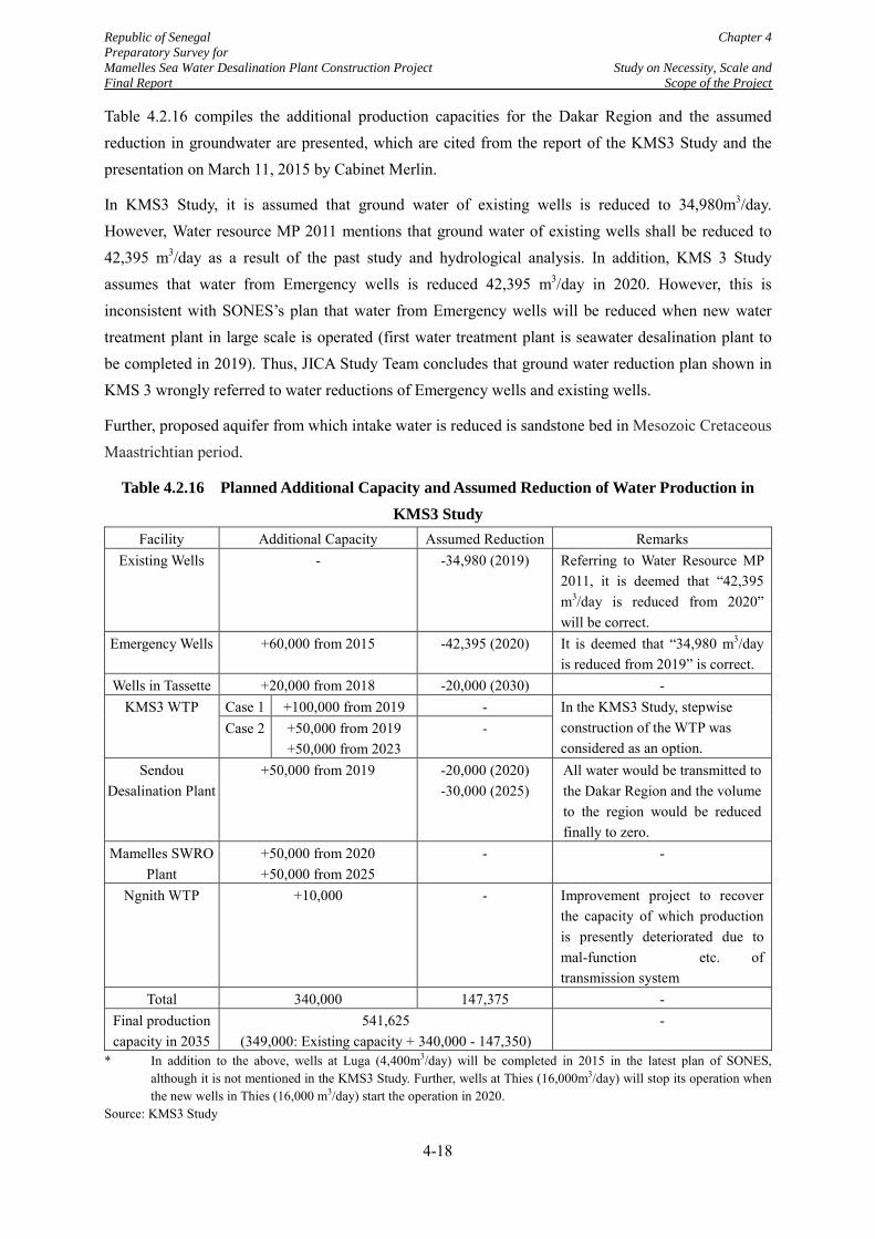
Republic of Senegal Chapter 4 Preparatory Survey for Mamelles Sea Water Desalination Plant Construction Project Study on Necessity, Scale and Final Report Scope of the Project
Table 4.2.16 compiles the additional production capacities for the Dakar Region and the assumed reduction in groundwater are presented, which are cited from the report of the KMS3 Study and the presentation on March 11, 2015 by Cabinet Merlin.
In KMS3 Study, it is assumed that ground water of existing wells is reduced to 34,980m3/day. However, Water resource MP 2011 mentions that ground water of existing wells shall be reduced to 42,395 m3/day as a result of the past study and hydrological analysis. In addition, KMS 3 Study assumes that water from Emergency wells is reduced 42,395 m3/day in 2020. However, this is inconsistent with SONES’s plan that water from Emergency wells will be reduced when new water treatment plant in large scale is operated (first water treatment plant is seawater desalination plant to be completed in 2019). Thus, JICA Study Team concludes that ground water reduction plan shown in KMS 3 wrongly referred to water reductions of Emergency wells and existing wells.
Further, proposed aquifer from which intake water is reduced is sandstone bed in Mesozoic Cretaceous Maastrichtian period.
Table 4.2.16 Planned Additional Capacity and Assumed Reduction of Water Production in KMS3 Study
Facility Additional Capacity Assumed Reduction Remarks Existing Wells - -34,980 (2019) Referring to Water Resource MP
2011, it is deemed that “42,395 m3/day is reduced from 2020” will be correct.
Emergency Wells +60,000 from 2015 -42,395 (2020) It is deemed that “34,980 m3/day is reduced from 2019” is correct.
Wells in Tassette +20,000 from 2018 -20,000 (2030) - KMS3 WTP Case 1 +100,000 from 2019 - In the KMS3 Study, stepwise
construction of the WTP was considered as an option.
Case 2 +50,000 from 2019 +50,000 from 2023
-
Sendou Desalination Plant
+50,000 from 2019 -20,000 (2020) -30,000 (2025)
All water would be transmitted to the Dakar Region and the volume to the region would be reduced finally to zero.
Mamelles SWRO Plant
+50,000 from 2020 +50,000 from 2025
- -
Ngnith WTP +10,000 - Improvement project to recover the capacity of which production is presently deteriorated due to mal-function etc. of transmission system
Total 340,000 147,375 - Final production capacity in 2035
541,625 (349,000: Existing capacity + 340,000 - 147,350)
-
* In addition to the above, wells at Luga (4,400m3/day) will be completed in 2015 in the latest plan of SONES, although it is not mentioned in the KMS3 Study. Further, wells at Thies (16,000m3/day) will stop its operation when the new wells in Thies (16,000 m3/day) start the operation in 2020.
Source: KMS3 Study
4-18
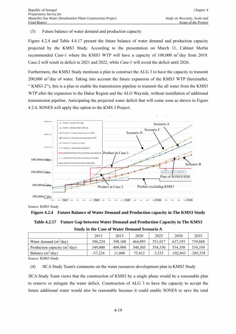
Republic of Senegal Chapter 4 Preparatory Survey for Mamelles Sea Water Desalination Plant Construction Project Study on Necessity, Scale and Final Report Scope of the Project
(3) Future balance of water demand and production capacity
Figure 4.2.4 and Table 4.4.17 present the future balance of water demand and production capacity projected by the KMS3 Study. According to the presentation on March 11, Cabinet Merlin recommended Case-1 where the KMS3 WTP will have a capacity of 100,000 m3/day from 2019. Case-2 will result in deficit in 2021 and 2022, while Case-1 will avoid the deficit until 2026.
Furthermore, the KMS3 Study mentions a plan to construct the ALG 3 to have the capacity to transmit 200,000 m3/day of water. Taking into account the future expansion of the KMS3 WTP (hereinafter, “ KMS3-2”), this is a plan to enable the transmission pipeline to transmit the all water from the KMS3 WTP after the expansion to the Dakar Region and the ALG Wayside, without installation of additional transmission pipeline. Anticipating the projected water deficit that will come soon as shown in Figure 4.2.4, SONES will apply this option to the KMS 3 Project.
Source: KMS3 Study
Figure 4.2.4 Future Balance of Water Demand and Production capacity in The KMS3 Study
Table 4.2.17 Future Gap between Water Demand and Production Capacity in The KMS3 Study in the Case of Water Demand Scenario A
2013 2015 2020 2025 2030 2035 Water demand (m3/day) 386,224 398,180 464,893 551,017 637,193 739,888 Production capacity (m3/day) 349,000 409,980 540,305 554,350 534,350 534,350 Balance (m3/day) -37,224 11,800 75,412 3,333 -102,843 -205,538
Source: KMS3 Study
(4) JICA Study Team's comments on the water resources development plan in KMS3 Study
JICA Study Team views that the construction of KMS3 by a single phase would be a reasonable plan to remove or mitigate the water deficit. Construction of ALG 3 to have the capacity to accept the future additional water would also be reasonable because it could enable SONES to save the total
Product in Case-1
Product in Case-2
Scenario A
Scenario D Scenario C
Plan of SONES/SDE
Scenario B
Product excluding KMS3
300,000m3/day
400,000m3/day
500,000m3/day
600,000m3/day
2015 2020 2025 2030 2035
4-19
Republic of Senegal Chapter 4 Preparatory Survey for Mamelles Sea Water Desalination Plant Construction Project Study on Necessity, Scale and Final Report Scope of the Project
investment in the long term and also save time for the future expansion to deliver the additional water to the Dakar Region.
As for the middle term to long term deficit from 2026, further expansion of the KMS WTP or KMS3-2 would be the first option as a countermeasure. Construction of the new seawater desalination plant could also be a possible option.
4-20

Republic of Senegal Chapter 4 Preparatory Survey for Mamelles Sea Water Desalination Plant Construction Project Study on Necessity, Scale and Final Report Scope of the Project
4.3 Necessity and Scale of the Project
Section 4.2 explained the present water resources development plan of SONES, modified in KMS3 Study. The JICA Study Team understands that the modified plan is the target to be aimed for by SONES, but does not assure its on-time implementation. In this section, the progress and schedule of the projects will be explained. In addition, the JICA Study Team will analyze the risks that could delay the implementation of the projects, and taking into account such possible delays, conclude the necessity and scale of the Project by a simulation of the future balance in water production and demand in different cases of the capacity of the Mamelles SWRO Plant.
4.3.1 Progress and Schedule of the Relevant Projects
(1) Ongoing and planned projects
Figure 4.3.1 shows the locations, capacities and completion years of the planned water production projects for Dakar region and the ALG Wayside.
4-21
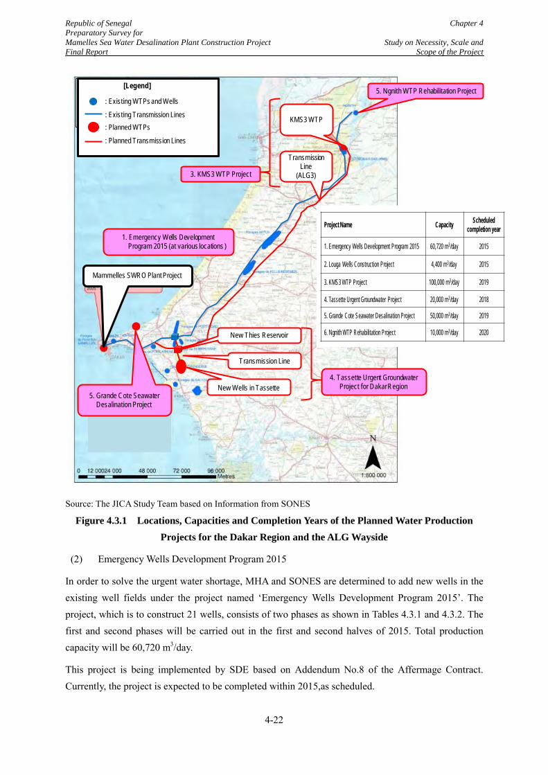
Republic of Senegal Chapter 4 Preparatory Survey for Mamelles Sea Water Desalination Plant Construction Project Study on Necessity, Scale and Final Report Scope of the Project
Source: The JICA Study Team based on Information from SONES
Figure 4.3.1 Locations, Capacities and Completion Years of the Planned Water Production Projects for the Dakar Region and the ALG Wayside
(2) Emergency Wells Development Program 2015
In order to solve the urgent water shortage, MHA and SONES are determined to add new wells in the existing well fields under the project named ‘Emergency Wells Development Program 2015’. The project, which is to construct 21 wells, consists of two phases as shown in Tables 4.3.1 and 4.3.2. The first and second phases will be carried out in the first and second halves of 2015. Total production capacity will be 60,720 m3/day.
This project is being implemented by SDE based on Addendum No.8 of the Affermage Contract. Currently, the project is expected to be completed within 2015,as scheduled.
[凡例]
既設浄水場及び井戸群 既設送水幹線 計画浄水場
5. Ngnith WTP Rehabilitation Project
Transmission Line
(ALG3)
New Wells in Tassette
New Thies Reservoir
5. Grande Cote Seawater Desalination Project
Mammelles SWRO Plant Project
Transmission Line
4. Tassette Urgent Groundwater Project for Dakar Region
: Existing WTPs and Wells
: Existing Transmission Lines: Planned WTPs
[Legend]
: Planned Transmission Lines
KMS3 WTP
3. KMS3 WTP Project
1. Emergency Wells Development Program 2015 (at various locations )
Project Name Capacity Scheduled completion year
1. Emergency Wells Development Program 2015 60,720 m3/day 2015
2. Louga Wells Construction Project 4,400 m3/day 2015
3. KMS3 WTP Project 100,000 m3/day 2019
4. Tassette Urgent Groundwater Project 20,000 m3/day 2018
5. Grande Cote Seawater Desalination Project 50,000 m3/day 2019
6. Ngnith WTP Rehabilitation Project 10,000 m3/day 2020
4-22
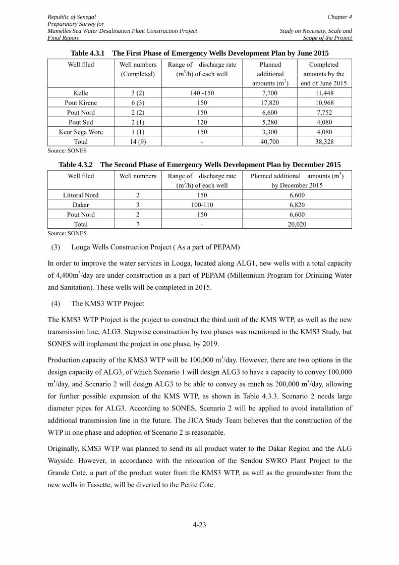
Republic of Senegal Chapter 4 Preparatory Survey for Mamelles Sea Water Desalination Plant Construction Project Study on Necessity, Scale and Final Report Scope of the Project
Table 4.3.1 The First Phase of Emergency Wells Development Plan by June 2015 Well filed Well numbers
(Completed) Range of discharge rate
(m3/h) of each well Planned
additional amounts (m3)
Completed amounts by the
end of June 2015 Kelle 3 (2) 140 -150 7,700 11,448
Pout Kirene 6 (3) 150 17,820 10,968 Pout Nord 2 (2) 150 6,600 7,752 Pout Sud 2 (1) 120 5,280 4,080
Keur Sega Wore 1 (1) 150 3,300 4,080 Total 14 (9) - 40,700 38,328
Source: SONES
Table 4.3.2 The Second Phase of Emergency Wells Development Plan by December 2015 Well filed Well numbers Range of discharge rate
(m3/h) of each well Planned additional amounts (m3)
by December 2015 Littoral Nord 2 150 6,600
Dakar 3 100-110 6,820 Pout Nord 2 150 6,600
Total 7 - 20,020 Source: SONES
(3) Louga Wells Construction Project ( As a part of PEPAM)
In order to improve the water services in Louga, located along ALG1, new wells with a total capacity of 4,400m3/day are under construction as a part of PEPAM (Millennium Program for Drinking Water and Sanitation). These wells will be completed in 2015.
(4) The KMS3 WTP Project
The KMS3 WTP Project is the project to construct the third unit of the KMS WTP, as well as the new transmission line, ALG3. Stepwise construction by two phases was mentioned in the KMS3 Study, but SONES will implement the project in one phase, by 2019.
Production capacity of the KMS3 WTP will be 100,000 m3/day. However, there are two options in the design capacity of ALG3, of which Scenario 1 will design ALG3 to have a capacity to convey 100,000 m3/day, and Scenario 2 will design ALG3 to be able to convey as much as 200,000 m3/day, allowing for further possible expansion of the KMS WTP, as shown in Table 4.3.3. Scenario 2 needs large diameter pipes for ALG3. According to SONES, Scenario 2 will be applied to avoid installation of additional transmission line in the future. The JICA Study Team believes that the construction of the WTP in one phase and adoption of Scenario 2 is reasonable.
Originally, KMS3 WTP was planned to send its all product water to the Dakar Region and the ALG Wayside. However, in accordance with the relocation of the Sendou SWRO Plant Project to the Grande Cote, a part of the product water from the KMS3 WTP, as well as the groundwater from the new wells in Tassette, will be diverted to the Petite Cote.
4-23
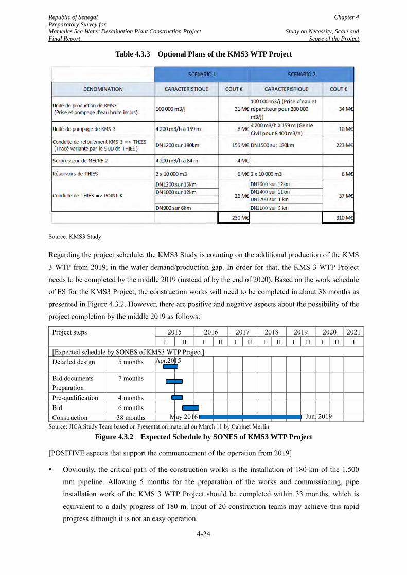
Republic of Senegal Chapter 4 Preparatory Survey for Mamelles Sea Water Desalination Plant Construction Project Study on Necessity, Scale and Final Report Scope of the Project
Table 4.3.3 Optional Plans of the KMS3 WTP Project
Source: KMS3 Study
Regarding the project schedule, the KMS3 Study is counting on the additional production of the KMS 3 WTP from 2019, in the water demand/production gap. In order for that, the KMS 3 WTP Project needs to be completed by the middle 2019 (instead of by the end of 2020). Based on the work schedule of ES for the KMS3 Project, the construction works will need to be completed in about 38 months as presented in Figure 4.3.2. However, there are positive and negative aspects about the possibility of the project completion by the middle 2019 as follows:
Project steps 2015 2016 2017 2018 2019 2020 2021 I II I II I II I II I II I II I
[Expected schedule by SONES of KMS3 WTP Project] Detailed design 5 months
Bid documents Preparation
7 months
Pre-qualification 4 months Bid 6 months Construction 38 months
Source: JICA Study Team based on Presentation material on March 11 by Cabinet Merlin
Figure 4.3.2 Expected Schedule by SONES of KMS3 WTP Project
[POSITIVE aspects that support the commencement of the operation from 2019]
Obviously, the critical path of the construction works is the installation of 180 km of the 1,500 mm pipeline. Allowing 5 months for the preparation of the works and commissioning, pipe installation work of the KMS 3 WTP Project should be completed within 33 months, which is equivalent to a daily progress of 180 m. Input of 20 construction teams may achieve this rapid progress although it is not an easy operation.
May 2016 Jun. 2019
Apr.2015
4-24
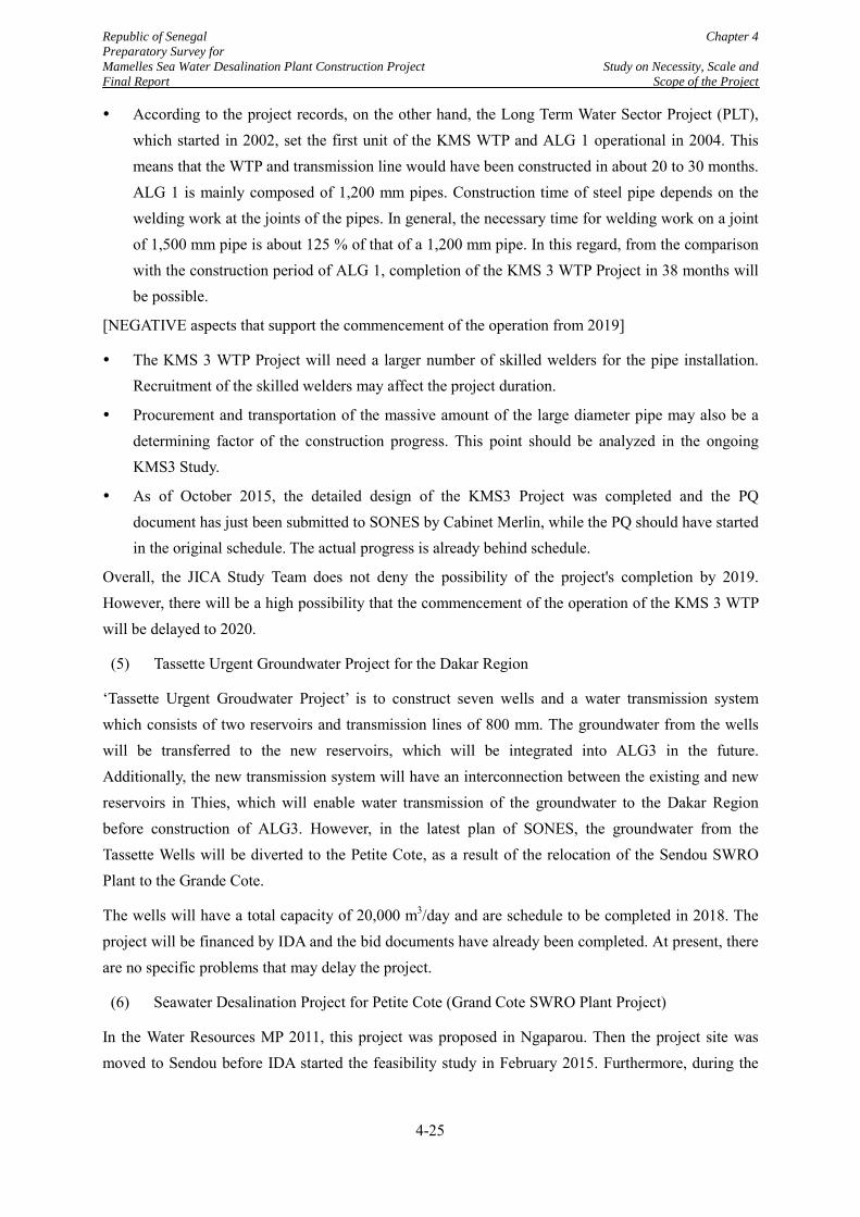
Republic of Senegal Chapter 4 Preparatory Survey for Mamelles Sea Water Desalination Plant Construction Project Study on Necessity, Scale and Final Report Scope of the Project
According to the project records, on the other hand, the Long Term Water Sector Project (PLT), which started in 2002, set the first unit of the KMS WTP and ALG 1 operational in 2004. This means that the WTP and transmission line would have been constructed in about 20 to 30 months. ALG 1 is mainly composed of 1,200 mm pipes. Construction time of steel pipe depends on the welding work at the joints of the pipes. In general, the necessary time for welding work on a joint of 1,500 mm pipe is about 125 % of that of a 1,200 mm pipe. In this regard, from the comparison with the construction period of ALG 1, completion of the KMS 3 WTP Project in 38 months will be possible.
[NEGATIVE aspects that support the commencement of the operation from 2019]
The KMS 3 WTP Project will need a larger number of skilled welders for the pipe installation. Recruitment of the skilled welders may affect the project duration.
Procurement and transportation of the massive amount of the large diameter pipe may also be a determining factor of the construction progress. This point should be analyzed in the ongoing KMS3 Study.
As of October 2015, the detailed design of the KMS3 Project was completed and the PQ document has just been submitted to SONES by Cabinet Merlin, while the PQ should have started in the original schedule. The actual progress is already behind schedule.
Overall, the JICA Study Team does not deny the possibility of the project's completion by 2019. However, there will be a high possibility that the commencement of the operation of the KMS 3 WTP will be delayed to 2020.
(5) Tassette Urgent Groundwater Project for the Dakar Region
‘Tassette Urgent Groudwater Project’ is to construct seven wells and a water transmission system which consists of two reservoirs and transmission lines of 800 mm. The groundwater from the wells will be transferred to the new reservoirs, which will be integrated into ALG3 in the future. Additionally, the new transmission system will have an interconnection between the existing and new reservoirs in Thies, which will enable water transmission of the groundwater to the Dakar Region before construction of ALG3. However, in the latest plan of SONES, the groundwater from the Tassette Wells will be diverted to the Petite Cote, as a result of the relocation of the Sendou SWRO Plant to the Grande Cote.
The wells will have a total capacity of 20,000 m3/day and are schedule to be completed in 2018. The project will be financed by IDA and the bid documents have already been completed. At present, there are no specific problems that may delay the project.
(6) Seawater Desalination Project for Petite Cote (Grand Cote SWRO Plant Project)
In the Water Resources MP 2011, this project was proposed in Ngaparou. Then the project site was moved to Sendou before IDA started the feasibility study in February 2015. Furthermore, during the
4-25
Republic of Senegal Chapter 4 Preparatory Survey for Mamelles Sea Water Desalination Plant Construction Project Study on Necessity, Scale and Final Report Scope of the Project
pre-feasibility study, the project site moved again to an area on the Grande Cote, which is on the western side of the Lac Rose.
Originally, this project was planned to provide the desalinated water exclusively to Petite Cote. However, because of the expanding concerns of water shortage in the capital region, SONES expected that the plant would function to supplement water to the capital region as well. After the relocation of the project to the Grande Cote, which is far to the Petite Cote, SONES has determined to send the all product water from the Grade Cote SWRO Plant to the Dakar Region, instead of the Petite Cote. Capacity of the desalination plant will be 50,000 m3/day and the scheduled completion year of the project is 2019.
MHA and SONES are going to implement the project by PPP scheme. BOOT (Build-Own-Operate-Transfer) is the most possible scheme and “Take or Pay” contract, under which the Client will always purchase the agreed volume of water regardless of the actual consumption, will be likely to be adopted
The pre-feasibility study, funded by IDA was completed. According to an interview with IDA, it has the intension to provide finance to employ consultants for tender assistance and supervision after SONES implements the environmental survey for the project but SONES is going to conduct a feasibility study by a finance from the International Funding Corporation (IFC) before the tender.
The environmental survey, which will be carried out in order to prepare an environmental impact assessment (EIA) report and to collect natural conditions data throughout a year for a detailed design by the contractor, has started, under the same contract as the EIA Study of the Mamelles SWRO Plant. The kick-off meeting between SONES and the consultant was held on 30th September, 2015.
The present views of the JICA Study Team on the possible schedule of the project from the information collected are given below:
If the entire procedure is implemented smoothly, the project will be completed in 2019 as shown in Figure 4.3.3.
Although the project site, determined to be located at Grande Cote, exact land for the project has not yet been finally identified. There is a risk that site identification and land acquisition will delay the project's progress.
The EIA Study has started in September 2015. However, the exact construction site of the SWRO plant has not been fixed yet. In the kick-off meeting on 30th September, the two sides discussed if the consultant would carry out the investigation on the multiple candidate sites or would wait for the final determination of the plant site. In these situations, EIA Study may not be completed as expected and the delayed acquisition of the ECC may slow the project.
This project is the first case for SONES to handle a PPP project. Although SONES will employ consultants to provide tender assistance and project supervision services, some difficulties are
4-26
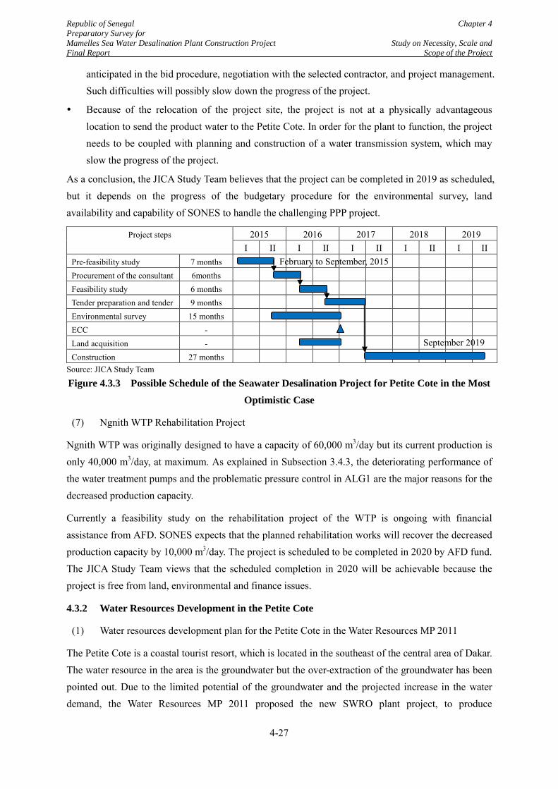
Republic of Senegal Chapter 4 Preparatory Survey for Mamelles Sea Water Desalination Plant Construction Project Study on Necessity, Scale and Final Report Scope of the Project
anticipated in the bid procedure, negotiation with the selected contractor, and project management. Such difficulties will possibly slow down the progress of the project.
Because of the relocation of the project site, the project is not at a physically advantageous location to send the product water to the Petite Cote. In order for the plant to function, the project needs to be coupled with planning and construction of a water transmission system, which may slow the progress of the project.
As a conclusion, the JICA Study Team believes that the project can be completed in 2019 as scheduled, but it depends on the progress of the budgetary procedure for the environmental survey, land availability and capability of SONES to handle the challenging PPP project.
Project steps 2015 2016 2017 2018 2019 I II I II I II I II I II
Pre-feasibility study 7 months Procurement of the consultant 6months Feasibility study 6 months Tender preparation and tender 9 months Environmental survey 15 months ECC - Land acquisition - Construction 27 months
Source: JICA Study Team
Figure 4.3.3 Possible Schedule of the Seawater Desalination Project for Petite Cote in the Most Optimistic Case
(7) Ngnith WTP Rehabilitation Project
Ngnith WTP was originally designed to have a capacity of 60,000 m3/day but its current production is only 40,000 m3/day, at maximum. As explained in Subsection 3.4.3, the deteriorating performance of the water treatment pumps and the problematic pressure control in ALG1 are the major reasons for the decreased production capacity.
Currently a feasibility study on the rehabilitation project of the WTP is ongoing with financial assistance from AFD. SONES expects that the planned rehabilitation works will recover the decreased production capacity by 10,000 m3/day. The project is scheduled to be completed in 2020 by AFD fund. The JICA Study Team views that the scheduled completion in 2020 will be achievable because the project is free from land, environmental and finance issues.
4.3.2 Water Resources Development in the Petite Cote
(1) Water resources development plan for the Petite Cote in the Water Resources MP 2011
The Petite Cote is a coastal tourist resort, which is located in the southeast of the central area of Dakar. The water resource in the area is the groundwater but the over-extraction of the groundwater has been pointed out. Due to the limited potential of the groundwater and the projected increase in the water demand, the Water Resources MP 2011 proposed the new SWRO plant project, to produce
September 2019
February to September, 2015
4-27
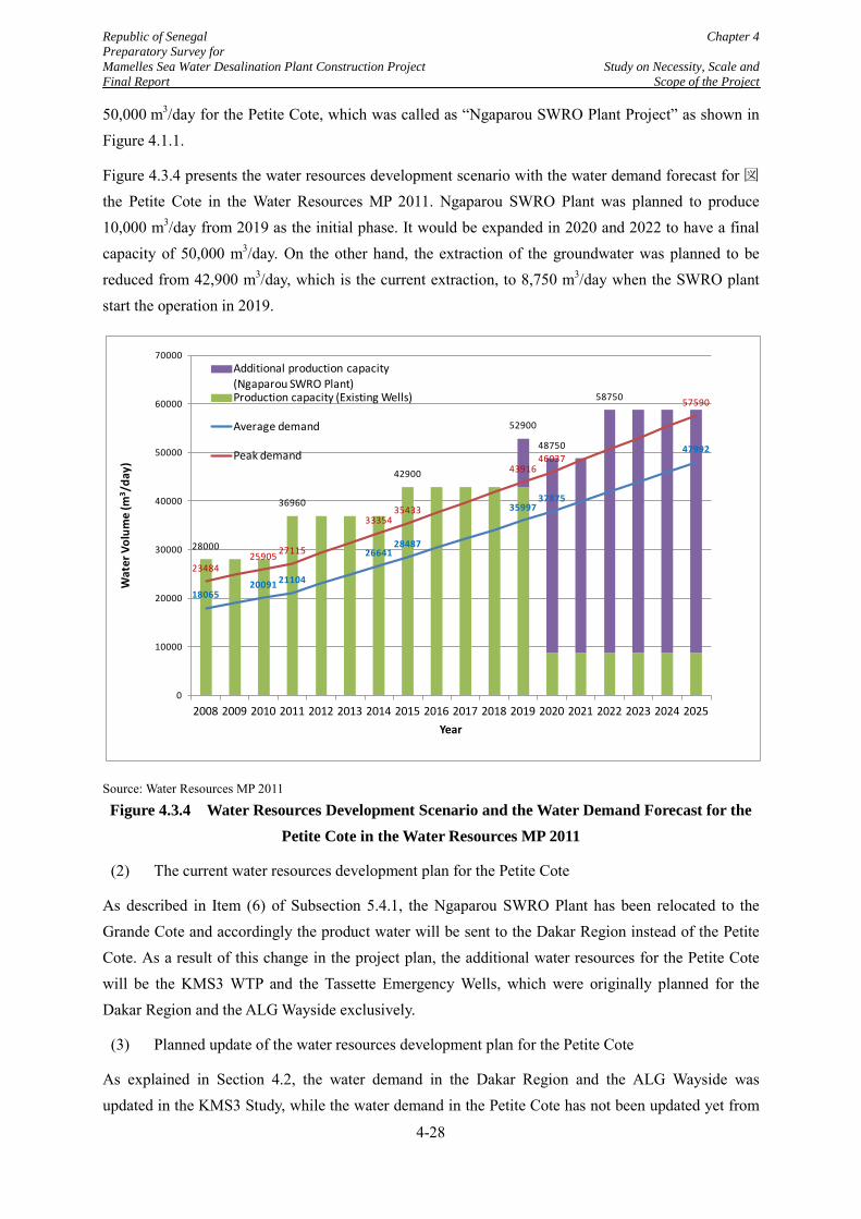
Republic of Senegal Chapter 4 Preparatory Survey for Mamelles Sea Water Desalination Plant Construction Project Study on Necessity, Scale and Final Report Scope of the Project
50,000 m3/day for the Petite Cote, which was called as “Ngaparou SWRO Plant Project” as shown in Figure 4.1.1.
Figure 4.3.4 presents the water resources development scenario with the water demand forecast for 図the Petite Cote in the Water Resources MP 2011. Ngaparou SWRO Plant was planned to produce 10,000 m3/day from 2019 as the initial phase. It would be expanded in 2020 and 2022 to have a final capacity of 50,000 m3/day. On the other hand, the extraction of the groundwater was planned to be reduced from 42,900 m3/day, which is the current extraction, to 8,750 m3/day when the SWRO plant start the operation in 2019.
Source: Water Resources MP 2011
Figure 4.3.4 Water Resources Development Scenario and the Water Demand Forecast for the Petite Cote in the Water Resources MP 2011
(2) The current water resources development plan for the Petite Cote
As described in Item (6) of Subsection 5.4.1, the Ngaparou SWRO Plant has been relocated to the Grande Cote and accordingly the product water will be sent to the Dakar Region instead of the Petite Cote. As a result of this change in the project plan, the additional water resources for the Petite Cote will be the KMS3 WTP and the Tassette Emergency Wells, which were originally planned for the Dakar Region and the ALG Wayside exclusively.
(3) Planned update of the water resources development plan for the Petite Cote
As explained in Section 4.2, the water demand in the Dakar Region and the ALG Wayside was updated in the KMS3 Study, while the water demand in the Petite Cote has not been updated yet from
1806520091 21104
2664128487
3599737875
47992
2348425905 27115
3335435433
4391646037
57590
28000
36960
42900
52900
48750
58750
0
10000
20000
30000
40000
50000
60000
70000
2008 2009 2010 2011 2012 2013 2014 2015 2016 2017 2018 2019 2020 2021 2022 2023 2024 2025
Wat
er V
olum
e (m
3 /da
y)
Year
Additional production capacity (Ngaparou SWRO Plant)Production capacity (Existing Wells)
Average demand
Peak demand
4-28
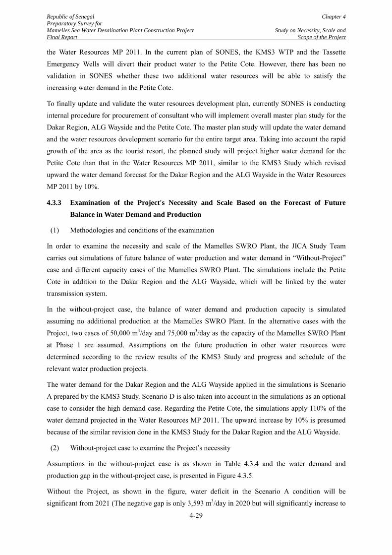
Republic of Senegal Chapter 4 Preparatory Survey for Mamelles Sea Water Desalination Plant Construction Project Study on Necessity, Scale and Final Report Scope of the Project
the Water Resources MP 2011. In the current plan of SONES, the KMS3 WTP and the Tassette Emergency Wells will divert their product water to the Petite Cote. However, there has been no validation in SONES whether these two additional water resources will be able to satisfy the increasing water demand in the Petite Cote.
To finally update and validate the water resources development plan, currently SONES is conducting internal procedure for procurement of consultant who will implement overall master plan study for the Dakar Region, ALG Wayside and the Petite Cote. The master plan study will update the water demand and the water resources development scenario for the entire target area. Taking into account the rapid growth of the area as the tourist resort, the planned study will project higher water demand for the Petite Cote than that in the Water Resources MP 2011, similar to the KMS3 Study which revised upward the water demand forecast for the Dakar Region and the ALG Wayside in the Water Resources MP 2011 by 10%.
4.3.3 Examination of the Project's Necessity and Scale Based on the Forecast of Future Balance in Water Demand and Production
(1) Methodologies and conditions of the examination
In order to examine the necessity and scale of the Mamelles SWRO Plant, the JICA Study Team carries out simulations of future balance of water production and water demand in “Without-Project” case and different capacity cases of the Mamelles SWRO Plant. The simulations include the Petite Cote in addition to the Dakar Region and the ALG Wayside, which will be linked by the water transmission system.
In the without-project case, the balance of water demand and production capacity is simulated assuming no additional production at the Mamelles SWRO Plant. In the alternative cases with the Project, two cases of 50,000 m3/day and 75,000 m3/day as the capacity of the Mamelles SWRO Plant at Phase 1 are assumed. Assumptions on the future production in other water resources were determined according to the review results of the KMS3 Study and progress and schedule of the relevant water production projects.
The water demand for the Dakar Region and the ALG Wayside applied in the simulations is Scenario A prepared by the KMS3 Study. Scenario D is also taken into account in the simulations as an optional case to consider the high demand case. Regarding the Petite Cote, the simulations apply 110% of the water demand projected in the Water Resources MP 2011. The upward increase by 10% is presumed because of the similar revision done in the KMS3 Study for the Dakar Region and the ALG Wayside.
(2) Without-project case to examine the Project’s necessity
Assumptions in the without-project case is as shown in Table 4.3.4 and the water demand and production gap in the without-project case, is presented in Figure 4.3.5.
Without the Project, as shown in the figure, water deficit in the Scenario A condition will be significant from 2021 (The negative gap is only 3,593 m3/day in 2020 but will significantly increase to
4-29
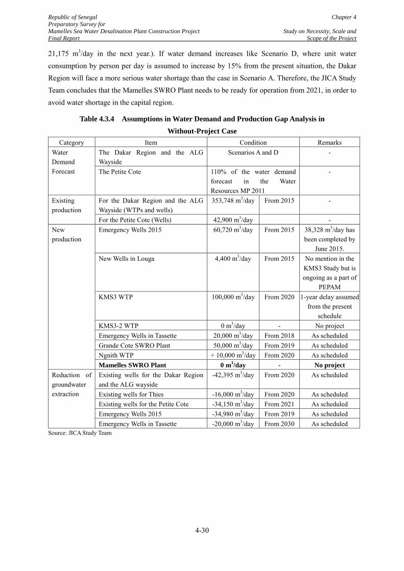
Republic of Senegal Chapter 4 Preparatory Survey for Mamelles Sea Water Desalination Plant Construction Project Study on Necessity, Scale and Final Report Scope of the Project
21,175 m3/day in the next year.). If water demand increases like Scenario D, where unit water consumption by person per day is assumed to increase by 15% from the present situation, the Dakar Region will face a more serious water shortage than the case in Scenario A. Therefore, the JICA Study Team concludes that the Mamelles SWRO Plant needs to be ready for operation from 2021, in order to avoid water shortage in the capital region.
Table 4.3.4 Assumptions in Water Demand and Production Gap Analysis in Without-Project Case
Category Item Condition Remarks Water Demand Forecast
The Dakar Region and the ALG Wayside
Scenarios A and D -
The Petite Cote 110% of the water demand forecast in the Water Resources MP 2011
-
Existing production
For the Dakar Region and the ALG Wayside (WTPs and wells)
353,748 m3/day From 2015 -
For the Petite Cote (Wells) 42,900 m3/day - New production
Emergency Wells 2015 60,720 m3/day From 2015 38,328 m3/day has been completed by
June 2015. New Wells in Louga 4,400 m3/day From 2015 No mention in the
KMS3 Study but is ongoing as a part of
PEPAM KMS3 WTP 100,000 m3/day From 2020 1-year delay assumed
from the present schedule
KMS3-2 WTP 0 m3/day - No project Emergency Wells in Tassette 20,000 m3/day From 2018 As scheduled Grande Cote SWRO Plant 50,000 m3/day From 2019 As scheduled Ngnith WTP + 10,000 m3/day From 2020 As scheduled Mamelles SWRO Plant 0 m3/day - No project
Reduction of groundwater extraction
Existing wells for the Dakar Region and the ALG wayside
-42,395 m3/day From 2020 As scheduled
Existing wells for Thies -16,000 m3/day From 2020 As scheduled Existing wells for the Petite Cote -34,150 m3/day From 2021 As scheduled Emergency Wells 2015 -34,980 m3/day From 2019 As scheduled Emergency Wells in Tassette -20,000 m3/day From 2030 As scheduled
Source: JICA Study Team
4-30
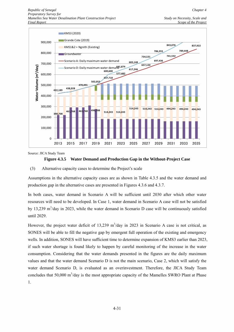
Republic of Senegal Chapter 4 Preparatory Survey for Mamelles Sea Water Desalination Plant Construction Project Study on Necessity, Scale and Final Report Scope of the Project
Source: JICA Study Team
Figure 4.3.5 Water Demand and Production Gap in the Without-Project Case
(3) Alternative capacity cases to determine the Project’s scale
Assumptions in the alternative capacity cases are as shown in Table 4.3.5 and the water demand and production gap in the alternative cases are presented in Figures 4.3.6 and 4.3.7.
In both cases, water demand in Scenario A will be sufficient until 2030 after which other water resources will need to be developed. In Case 1, water demand in Scenario A case will not be satisfied by 13,239 m3/day in 2023, while the water demand in Scenario D case will be continuously satisfied until 2029.
However, the project water deficit of 13,239 m3/day in 2023 in Scenario A case is not critical, as SONES will be able to fill the negative gap by emergent full operation of the existing and emergency wells. In addition, SONES will have sufficient time to determine expansion of KMS3 earlier than 2023, if such water shortage is found likely to happen by careful monitoring of the increase in the water consumption. Considering that the water demands presented in the figures are the daily maximum values and that the water demand Scenario D is not the main scenario, Case 2, which will satisfy the water demand Scenario D, is evaluated as an overinvestment. Therefore, the JICA Study Team concludes that 50,000 m3/day is the most appropriate capacity of the Mamelles SWRO Plant at Phase 1.
537,718
577,482
617,246
657,120
697,436
741,532
789,448
837,922
422,189 438,928
470,491 502,053
600,600
641,874
683,148
734,531
786,355
843,076
390,708 461,768 461,768 496,788
514,243 514,243 514,243 514,243 514,243 494,243 494,243 494,243
0
100,000
200,000
300,000
400,000
500,000
600,000
700,000
800,000
900,000
2013 2015 2017 2019 2021 2023 2025 2027 2029 2031 2033 2035
Wat
er V
olum
e (m
3 /da
y)KMS3 (2020)
Grande Cote (2019)
KMS1&2 + Ngnith (Existing)
Groundwater
Scenario A: Daily maximum water demand
Scenario D: Daily maximum water demand
4-31
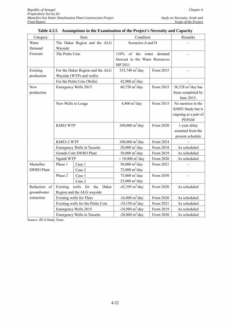
Republic of Senegal Chapter 4 Preparatory Survey for Mamelles Sea Water Desalination Plant Construction Project Study on Necessity, Scale and Final Report Scope of the Project
Table 4.3.5 Assumptions in the Examination of the Project's Necessity and Capacity Category Item Condition Remarks
Water Demand Forecast
The Dakar Region and the ALG Wayside
Scenarios A and D -
The Petite Cote 110% of the water demand forecast in the Water Resources MP 2011
-
Existing production
For the Dakar Region and the ALG Wayside (WTPs and wells)
353,748 m3/day From 2015 -
For the Petite Cote (Wells) 42,900 m3/day - New production
Emergency Wells 2015 60,720 m3/day From 2015 38,328 m3/day has been completed by
June 2015. New Wells in Louga 4,400 m3/day From 2015 No mention in the
KMS3 Study but is ongoing as a part of
PEPAM KMS3 WTP 100,000 m3/day From 2020 1-year delay
assumed from the present schedule
KMS3-2 WTP 100,000 m3/day From 2024 - Emergency Wells in Tassette 20,000 m3/day From 2018 As scheduled Grande Cote SWRO Plant 50,000 m3/day From 2019 As scheduled Ngnith WTP + 10,000 m3/day From 2020 As scheduled
Mamelles SWRO Plant
Phase 1 Case 1 50,000 m3/day 75,000 m3/day
From 2021 - Case 2
Phase 2 Case 1 75,000 m3/day 25,000 m3/day
From 2030 - Case 2
Reduction of groundwater extraction
Existing wells for the Dakar Region and the ALG wayside
-42,395 m3/day From 2020 As scheduled
Existing wells for Thies -16,000 m3/day From 2020 As scheduled Existing wells for the Petite Cote -34,150 m3/day From 2021 As scheduled Emergency Wells 2015 -34,980 m3/day From 2019 As scheduled Emergency Wells in Tassette -20,000 m3/day From 2030 As scheduled
Source: JICA Study Team
4-32
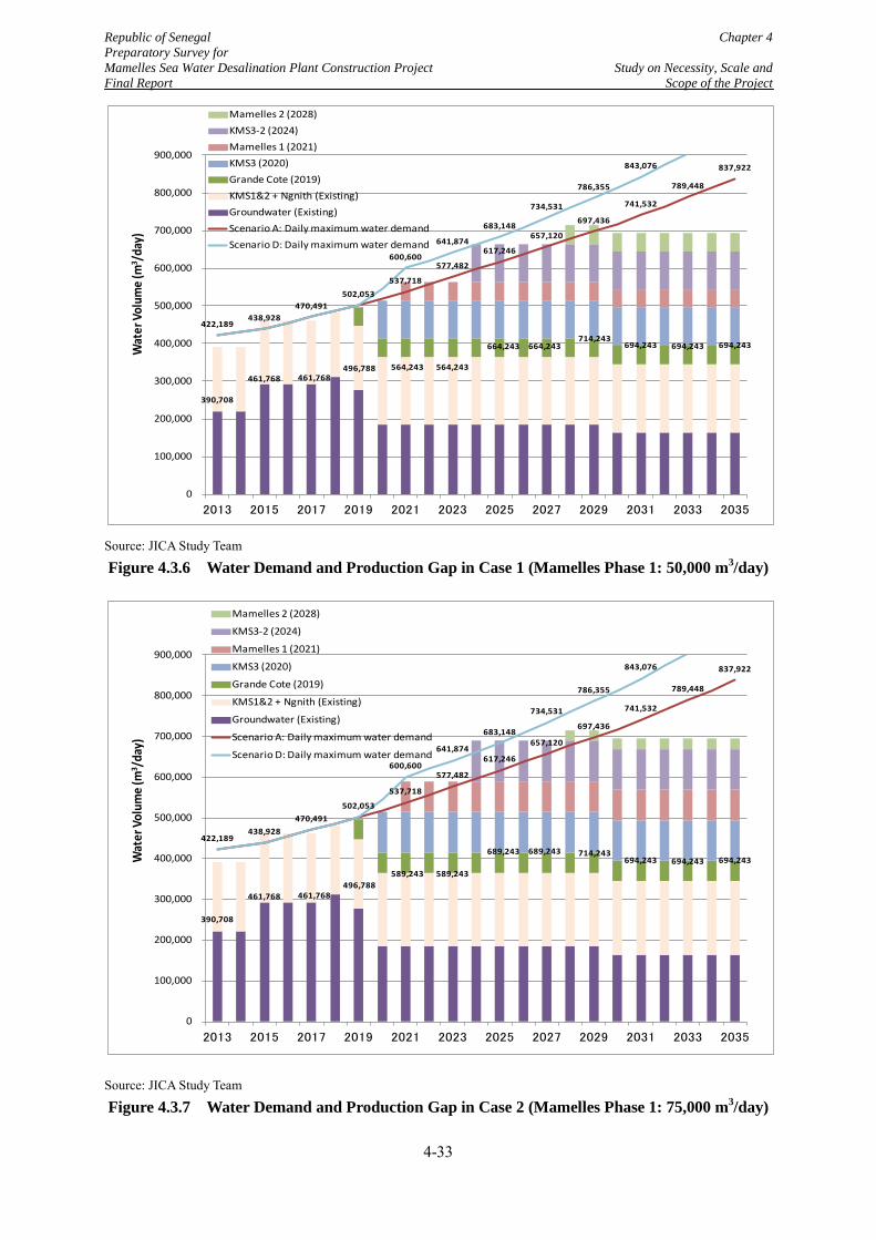
Republic of Senegal Chapter 4 Preparatory Survey for Mamelles Sea Water Desalination Plant Construction Project Study on Necessity, Scale and Final Report Scope of the Project
Source: JICA Study Team
Figure 4.3.6 Water Demand and Production Gap in Case 1 (Mamelles Phase 1: 50,000 m3/day)
Source: JICA Study Team
Figure 4.3.7 Water Demand and Production Gap in Case 2 (Mamelles Phase 1: 75,000 m3/day)
537,718
577,482
617,246
657,120
697,436
741,532
789,448
837,922
422,189 438,928
470,491 502,053
600,600
641,874
683,148
734,531
786,355
843,076
390,708
461,768 461,768 496,788 564,243 564,243
664,243 664,243 714,243
694,243 694,243 694,243
0
100,000
200,000
300,000
400,000
500,000
600,000
700,000
800,000
900,000
2013 2015 2017 2019 2021 2023 2025 2027 2029 2031 2033 2035
Wat
er Vo
lum
e (m
3 /day
)
Mamelles 2 (2028)KMS3-2 (2024)Mamelles 1 (2021)KMS3 (2020)Grande Cote (2019)KMS1&2 + Ngnith (Existing)Groundwater (Existing)Scenario A: Daily maximum water demandScenario D: Daily maximum water demand
537,718
577,482
617,246
657,120
697,436
741,532
789,448
837,922
422,189 438,928
470,491 502,053
600,600
641,874
683,148
734,531
786,355
843,076
390,708
461,768 461,768 496,788
589,243 589,243
689,243 689,243 714,243 694,243 694,243 694,243
0
100,000
200,000
300,000
400,000
500,000
600,000
700,000
800,000
900,000
2013 2015 2017 2019 2021 2023 2025 2027 2029 2031 2033 2035
Wat
er V
olum
e (m
3 /day
)
Mamelles 2 (2028)
KMS3-2 (2024)
Mamelles 1 (2021)
KMS3 (2020)
Grande Cote (2019)
KMS1&2 + Ngnith (Existing)
Groundwater (Existing)
Scenario A: Daily maximum water demand
Scenario D: Daily maximum water demand
4-33
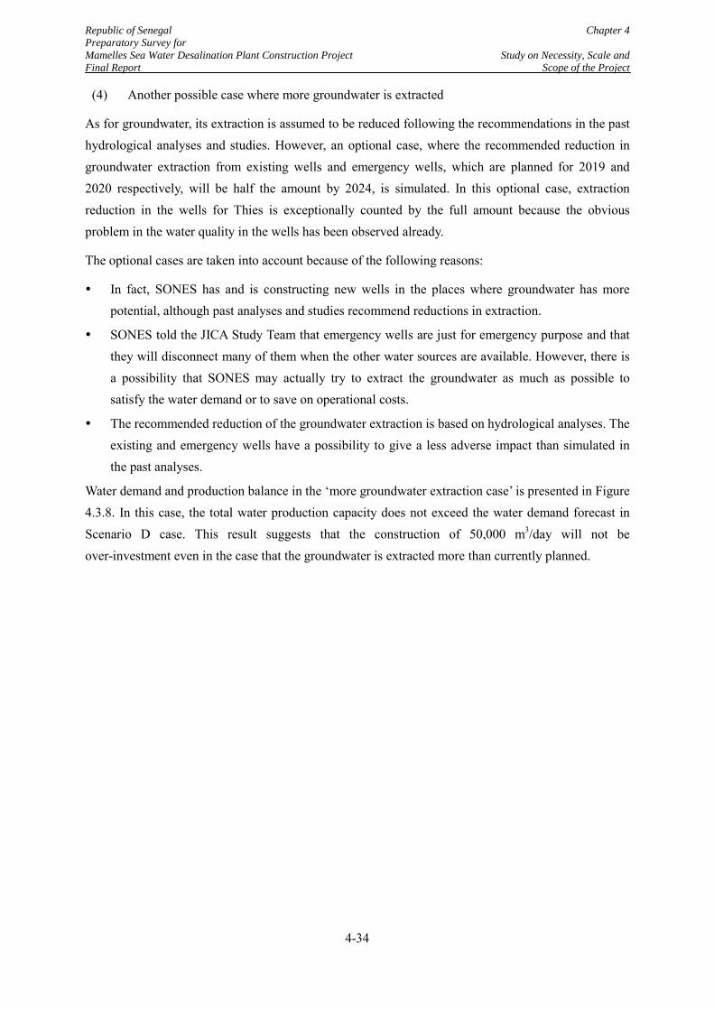
Republic of Senegal Chapter 4 Preparatory Survey for Mamelles Sea Water Desalination Plant Construction Project Study on Necessity, Scale and Final Report Scope of the Project
(4) Another possible case where more groundwater is extracted
As for groundwater, its extraction is assumed to be reduced following the recommendations in the past hydrological analyses and studies. However, an optional case, where the recommended reduction in groundwater extraction from existing wells and emergency wells, which are planned for 2019 and 2020 respectively, will be half the amount by 2024, is simulated. In this optional case, extraction reduction in the wells for Thies is exceptionally counted by the full amount because the obvious problem in the water quality in the wells has been observed already.
The optional cases are taken into account because of the following reasons:
In fact, SONES has and is constructing new wells in the places where groundwater has more potential, although past analyses and studies recommend reductions in extraction.
SONES told the JICA Study Team that emergency wells are just for emergency purpose and that they will disconnect many of them when the other water sources are available. However, there is a possibility that SONES may actually try to extract the groundwater as much as possible to satisfy the water demand or to save on operational costs.
The recommended reduction of the groundwater extraction is based on hydrological analyses. The existing and emergency wells have a possibility to give a less adverse impact than simulated in the past analyses.
Water demand and production balance in the ‘more groundwater extraction case’ is presented in Figure 4.3.8. In this case, the total water production capacity does not exceed the water demand forecast in Scenario D case. This result suggests that the construction of 50,000 m3/day will not be over-investment even in the case that the groundwater is extracted more than currently planned.
4-34
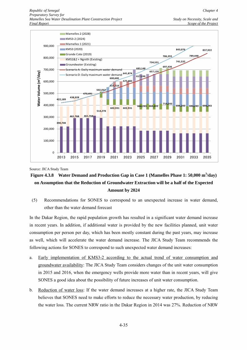
Republic of Senegal Chapter 4 Preparatory Survey for Mamelles Sea Water Desalination Plant Construction Project Study on Necessity, Scale and Final Report Scope of the Project
Source: JICA Study Team
Figure 4.3.8 Water Demand and Production Gap in Case 1 (Mamelles Phase 1: 50,000 m3/day) on Assumption that the Reduction of Groundwater Extraction will be a half of the Expected
Amount by 2024
(5) Recommendations for SONES to correspond to an unexpected increase in water demand, other than the water demand forecast
In the Dakar Region, the rapid population growth has resulted in a significant water demand increase in recent years. In addition, if additional water is provided by the new facilities planned, unit water consumption per person per day, which has been mostly constant during the past years, may increase as well, which will accelerate the water demand increase. The JICA Study Team recommends the following actions for SONES to correspond to such unexpected water demand increases:
a. Early implementation of KMS3-2 according to the actual trend of water consumption and groundwater availability: The JICA Study Team considers changes of the unit water consumption in 2015 and 2016, when the emergency wells provide more water than in recent years, will give SONES a good idea about the possibility of future increases of unit water consumption.
b. Reduction of water loss: If the water demand increases at a higher rate, the JICA Study Team believes that SONES need to make efforts to reduce the necessary water production, by reducing the water loss. The current NRW ratio in the Dakar Region in 2014 was 27%. Reduction of NRW
537,718
577,482
617,246
657,120
697,436
741,532
789,448
837,922
422,189 438,928
470,491 502,053
600,600
641,874
683,148
734,531
786,355
843,076
390,708
461,768 461,768
514,278 602,931 602,931
664,243 664,243 714,243
694,243 694,243 694,243
0
100,000
200,000
300,000
400,000
500,000
600,000
700,000
800,000
900,000
2013 2015 2017 2019 2021 2023 2025 2027 2029 2031 2033 2035
Wat
er V
olum
e (m
3 /day
)Mamelles 2 (2028)
KMS3-2 (2024)
Mamelles 1 (2021)
KMS3 (2020)
Grande Cote (2019)
KMS1&2 + Ngnith (Existing)
Groundwater (Existing)
Scenario A: Daily maximum water demand
Scenario D: Daily maximum water demand
4-35
Republic of Senegal Chapter 4 Preparatory Survey for Mamelles Sea Water Desalination Plant Construction Project Study on Necessity, Scale and Final Report Scope of the Project
ratio from 21.1% to 15%, which is the agreed target value between SONES and SDE, will lower the necessary production by 7%.
c. Control of water consumption for irrigation purpose: The present water consumption for agricultural purpose is about 15,000 m3/day. Some efforts to control the irrigational water demand are ongoing, which the JICA Study Team considers reasonable and needs to be continued:
According to the Affermage Contract, agricultural water will be limited to daily consumption of 12,000 m3, on the condition that the groundwater from Thiaroye and recycled water from the Cambérène wastewater treatment plant are supplemented.
At present, conversion of the water use purpose of groundwater from some wells in Thiaroye for agricultural purpose is ongoing. By this effort, demand increase in the agriculture sector will be limited.
4.3.4 Simulation of Operational Rate of the Mamelles SWRO Plant
(1) Conditions of the simulation
Operation rate or production amount of the Mamelles SWRO Plant will be different from water demand. As the water demand fluctuates, Operation rate of the Mamelles SWRO Plant is simulated to evaluate the validity of the determined project scale based on the following conditions:
Production of the respective water resources will be simulated for each case on maximum, average and minimum daily water demand case in the Dakar Region. Finally, simulation results for each demand case will be summed up to compute annual average and maximum productions of the Mamelles SWRO Plant for each year until 2035.
Average and minimum water demands are calculated based on a daily peak factor (= Daily maximum demand / Daily average demand) of 1.1. All demand cases are assumed to be observed for the same durations in a year (122 days in a year).
Assumed development scenario of the water resources in the simulation is Case 1in Table 4.3.5. The phase 1 capacity of the Mamelles SWRO Plant is 50,000 m3/day and the assumed water demand is Scenario A.
Priority of the operation depends on the assumed operation cost of water resources, except for the Grande Cote SWRO Plant, to which “Take or Pay” contract will be applied. For example, the operation of the KMS3 WTP will be prioritized higher than that of the Mamelles SWRO Plant. Accordingly, the operation priority of the water resources existing and planned is 1) Grande Cote SWRO Plant, 2) Wells, 3) KMS 1&2 and Ngith WTPs, 4) KMS 3 WTP, 5) KMS3-2 WTP, 6) Mamelles SWRO Plant Phase 1, and 7) the Mamelles SWRO Plant Phase 2, and 6) Grande Cote SWRO Plant. The Grande Cote SWRO Plant will always operate at the full capacity of 50,000 m3/day in the simulation.
Regarding the Mamelles SWRO Plant Phases 1 and 2, at least one unit, which will have a capacity of 10,000 m3/day production, will be in constant operation to maintain the function of the plant.
4-36
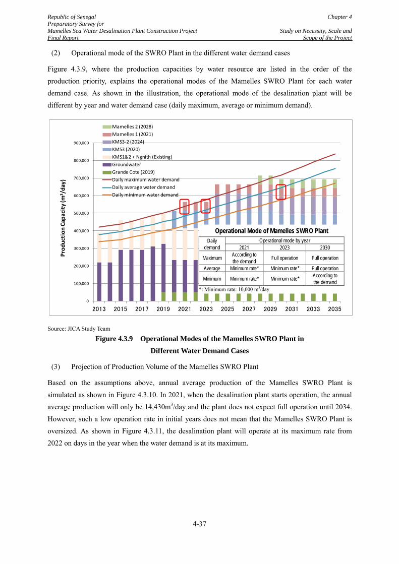
Republic of Senegal Chapter 4 Preparatory Survey for Mamelles Sea Water Desalination Plant Construction Project Study on Necessity, Scale and Final Report Scope of the Project
(2) Operational mode of the SWRO Plant in the different water demand cases
Figure 4.3.9, where the production capacities by water resource are listed in the order of the production priority, explains the operational modes of the Mamelles SWRO Plant for each water demand case. As shown in the illustration, the operational mode of the desalination plant will be different by year and water demand case (daily maximum, average or minimum demand).
Source: JICA Study Team
Figure 4.3.9 Operational Modes of the Mamelles SWRO Plant in Different Water Demand Cases
(3) Projection of Production Volume of the Mamelles SWRO Plant
Based on the assumptions above, annual average production of the Mamelles SWRO Plant is simulated as shown in Figure 4.3.10. In 2021, when the desalination plant starts operation, the annual average production will only be 14,430m3/day and the plant does not expect full operation until 2034. However, such a low operation rate in initial years does not mean that the Mamelles SWRO Plant is oversized. As shown in Figure 4.3.11, the desalination plant will operate at its maximum rate from 2022 on days in the year when the water demand is at its maximum.
0
100,000
200,000
300,000
400,000
500,000
600,000
700,000
800,000
900,000
2013 2015 2017 2019 2021 2023 2025 2027 2029 2031 2033 2035
Prod
uctio
n Ca
paci
ty (m
3 /da
y)
Mamelles 2 (2028)Mamelles 1 (2021)KMS3-2 (2024)KMS3 (2020)KMS1&2 + Ngnith (Existing)GroundwaterGrande Cote (2019)Daily maximum water demandDaily average water demandDaily minimum water demand
Operational Mode of Mamelles SWRO Plant Daily
demand Operational mode by year
2021 2023 2030
Maximum According to the demand Full operation Full operation
Average Minimum rate* Minimum rate* Full operation
Minimum Minimum rate* Minimum rate* According to the demand
*: Minimum rate: 10,000 m3/day
4-37
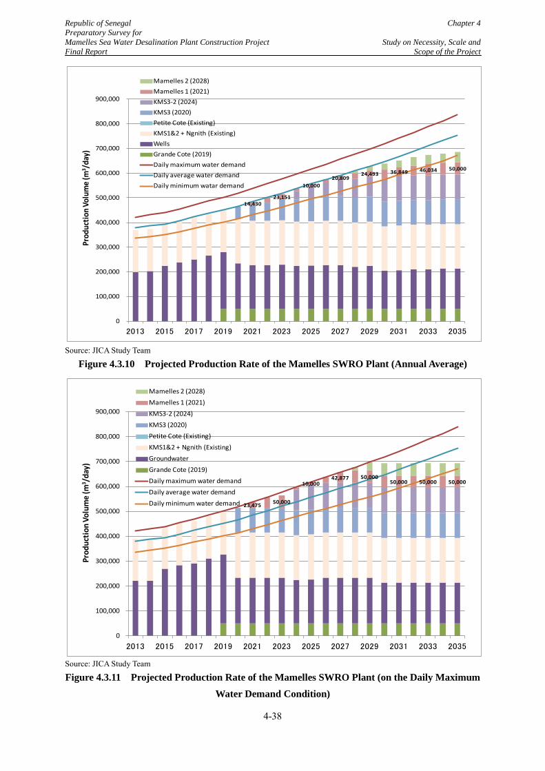
Republic of Senegal Chapter 4 Preparatory Survey for Mamelles Sea Water Desalination Plant Construction Project Study on Necessity, Scale and Final Report Scope of the Project
Source: JICA Study Team
Figure 4.3.10 Projected Production Rate of the Mamelles SWRO Plant (Annual Average)
Source: JICA Study Team
Figure 4.3.11 Projected Production Rate of the Mamelles SWRO Plant (on the Daily Maximum Water Demand Condition)
14,430 23,151
10,000 20,809
24,493 36,849 46,034 50,000
0
100,000
200,000
300,000
400,000
500,000
600,000
700,000
800,000
900,000
2013 2015 2017 2019 2021 2023 2025 2027 2029 2031 2033 2035
Prod
uctio
n Vo
lum
e (m
3 /day
)Mamelles 2 (2028)Mamelles 1 (2021)KMS3-2 (2024)KMS3 (2020)Petite Cote (Existing)KMS1&2 + Ngnith (Existing)WellsGrande Cote (2019)Daily maximum water demandDaily average water demandDaily minimum watar demand
23,475 50,000
10,000 42,877 50,000
50,000 50,000 50,000
0
100,000
200,000
300,000
400,000
500,000
600,000
700,000
800,000
900,000
2013 2015 2017 2019 2021 2023 2025 2027 2029 2031 2033 2035
Prod
uctio
n Vo
lum
e (m
3 /day
)
Mamelles 2 (2028)Mamelles 1 (2021)KMS3-2 (2024)KMS3 (2020)Petite Cote (Existing)KMS1&2 + Ngnith (Existing)GroundwaterGrande Cote (2019)Daily maximum water demandDaily average water demandDaily minimum water demand
4-38
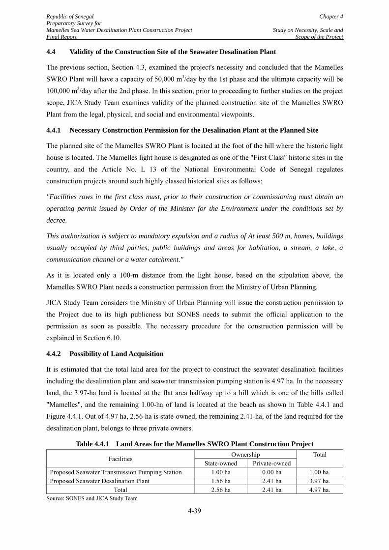
Republic of Senegal Chapter 4 Preparatory Survey for Mamelles Sea Water Desalination Plant Construction Project Study on Necessity, Scale and Final Report Scope of the Project
4.4 Validity of the Construction Site of the Seawater Desalination Plant
The previous section, Section 4.3, examined the project's necessity and concluded that the Mamelles SWRO Plant will have a capacity of 50,000 m3/day by the 1st phase and the ultimate capacity will be 100,000 m3/day after the 2nd phase. In this section, prior to proceeding to further studies on the project scope, JICA Study Team examines validity of the planned construction site of the Mamelles SWRO Plant from the legal, physical, and social and environmental viewpoints.
4.4.1 Necessary Construction Permission for the Desalination Plant at the Planned Site
The planned site of the Mamelles SWRO Plant is located at the foot of the hill where the historic light house is located. The Mamelles light house is designated as one of the "First Class" historic sites in the country, and the Article No. L 13 of the National Environmental Code of Senegal regulates construction projects around such highly classed historical sites as follows:
"Facilities rows in the first class must, prior to their construction or commissioning must obtain an operating permit issued by Order of the Minister for the Environment under the conditions set by decree.
This authorization is subject to mandatory expulsion and a radius of At least 500 m, homes, buildings usually occupied by third parties, public buildings and areas for habitation, a stream, a lake, a communication channel or a water catchment."
As it is located only a 100-m distance from the light house, based on the stipulation above, the Mamelles SWRO Plant needs a construction permission from the Ministry of Urban Planning.
JICA Study Team considers the Ministry of Urban Planning will issue the construction permission to the Project due to its high publicness but SONES needs to submit the official application to the permission as soon as possible. The necessary procedure for the construction permission will be explained in Section 6.10.
4.4.2 Possibility of Land Acquisition
It is estimated that the total land area for the project to construct the seawater desalination facilities including the desalination plant and seawater transmission pumping station is 4.97 ha. In the necessary land, the 3.97-ha land is located at the flat area halfway up to a hill which is one of the hills called "Mamelles", and the remaining 1.00-ha of land is located at the beach as shown in Table 4.4.1 and Figure 4.4.1. Out of 4.97 ha, 2.56-ha is state-owned, the remaining 2.41-ha, of the land required for the desalination plant, belongs to three private owners.
Table 4.4.1 Land Areas for the Mamelles SWRO Plant Construction Project
Facilities Ownership Total
State-owned Private-owned Proposed Seawater Transmission Pumping Station 1.00 ha 0.00 ha 1.00 ha. Proposed Seawater Desalination Plant 1.56 ha 2.41 ha 3.97 ha.
Total 2.56 ha 2.41 ha 4.97 ha. Source: SONES and JICA Study Team
4-39
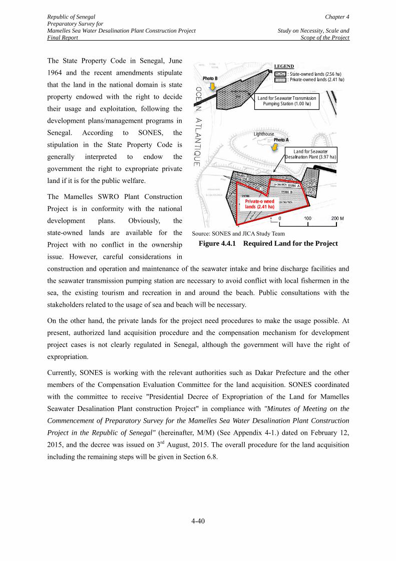
Republic of Senegal Chapter 4 Preparatory Survey for Mamelles Sea Water Desalination Plant Construction Project Study on Necessity, Scale and Final Report Scope of the Project
The State Property Code in Senegal, June 1964 and the recent amendments stipulate that the land in the national domain is state property endowed with the right to decide their usage and exploitation, following the development plans/management programs in Senegal. According to SONES, the stipulation in the State Property Code is generally interpreted to endow the government the right to expropriate private land if it is for the public welfare.
The Mamelles SWRO Plant Construction Project is in conformity with the national development plans. Obviously, the state-owned lands are available for the Project with no conflict in the ownership issue. However, careful considerations in construction and operation and maintenance of the seawater intake and brine discharge facilities and the seawater transmission pumping station are necessary to avoid conflict with local fishermen in the sea, the existing tourism and recreation in and around the beach. Public consultations with the stakeholders related to the usage of sea and beach will be necessary.
On the other hand, the private lands for the project need procedures to make the usage possible. At present, authorized land acquisition procedure and the compensation mechanism for development project cases is not clearly regulated in Senegal, although the government will have the right of expropriation.
Currently, SONES is working with the relevant authorities such as Dakar Prefecture and the other members of the Compensation Evaluation Committee for the land acquisition. SONES coordinated with the committee to receive "Presidential Decree of Expropriation of the Land for Mamelles Seawater Desalination Plant construction Project" in compliance with "Minutes of Meeting on the Commencement of Preparatory Survey for the Mamelles Sea Water Desalination Plant Construction Project in the Republic of Senegal" (hereinafter, M/M) (See Appendix 4-1.) dated on February 12, 2015, and the decree was issued on 3rd August, 2015. The overall procedure for the land acquisition including the remaining steps will be given in Section 6.8.
Source: SONES and JICA Study Team
Figure 4.4.1 Required Land for the Project
LEGEND: State-owned lands (2.56 ha): Private-owned lands (2.41 ha)
Land for Seawater Transmission Pumping Station (1.00 ha)
Land for SeawaterDesalination Plant (3.97 ha)
Private-o wned lands (2.41 ha)
LighthousePhoto A
Photo B
4-40

Republic of Senegal Chapter 4 Preparatory Survey for Mamelles Sea Water Desalination Plant Construction Project Study on Necessity, Scale and Final Report Scope of the Project
4.4.3 Possible Capacity of the Desalination Plant in the Planned Site
Excluding the land for the seawater transmission pumping station, SONES planned to acquire 6 ha of land for the desalination plant. However, available land for the plant turned out to be 3.9 ha because the neighboring areas were already reserved for a scheduled hotel business, which raised a question for SONES if the land can contain the seawater desalination plant of the ultimate capacity of 100,000 m3/day.
Area requirement of a desalination plant of 1 m3/day capacity depends on the scale of the plant. In the case of the middle to large scale seawater desalination plant of reverse osmosis (RO) technology, with a capacity of approximately 50,000 m3/day or more, area requirement is generally 0.25 to 0.60 m2 per 1m3/day production capacity, from the worldwide practices of the same type of plants.
Assuming the 3.9 ha land for the 100,000 m3/day plant, as shown in Table 4.4.1, available area by production capacity is 0.39 m2/(m3/day) and it is within the practical range of the area requirement, 0.25 to 0.6 m2/(m3/day). Therefore, it is concluded that the ultimate capacity of 100,000 m3/day will be possible with an available land of 3.9 ha.
Table 4.4.2 Examination of Area Requirement of the Mamelles Seawater Desalination Plant Ultimate capacity Available area Area/Capacity General area
Requirement*1 100,000 m3/day 3.9 ha 0.39 m2/(m3/day) 0.25 - 0.60 m2/(m3/day)*2
[Conclusion] Area/capacity (3.9) > Minimum area requirement (0.25) => 100,000 m3/day plant is possible in the 3.9 ha land.
*1: General area requirement of seawater desalination plant by RO of 50,000 m3/day or more, from the worldwide practices of the same type plants
*2: Minimum area requirement used be about 0.40 m2/(m3/day) but recently more compact plants have been constructed. Source: JICA Study Team
Photo A Photo B
[Land for the seawater desalination plant] [Beach near the seawater pumping station] Source: JICA Study Team
Photo 4.4.1 Present Situations of the Land for the Project
Plant Site
4-41
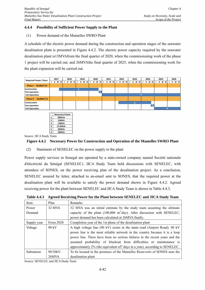
Republic of Senegal Chapter 4 Preparatory Survey for Mamelles Sea Water Desalination Plant Construction Project Study on Necessity, Scale and Final Report Scope of the Project
4.4.4 Possibility of Sufficient Power Supply to the Plant
(1) Power demand of the Mamelles SWRO Plant
A schedule of the electric power demand during the construction and operation stages of the seawater desalination plant is presented in Figure 4.4.2. The electric power capacity required by the seawater desalination plant is13MVAfrom the final quarter of 2020, when the commissioning work of the phase 1 project will be carried out, and 26MVAthe final quarter of 2025, when the commissioning work for the plant expansion will be carried out.
Source: JICA Study Team
Figure 4.4.2 Necessary Power for Construction and Operation of the Mamelles SWRO Plant
(2) Statement of SENELEC on the power supply to the plant
Power supply services in Senegal are operated by a state-owned company named Société nationale d'électricité du Sénégal (SENELEC). JICA Study Team held discussions with SENELEC, with attendees of SONES, on the power receiving plan of the desalination project. As a conclusion, SENELEC assured by letter, attached to an-email sent to SONES, that the required power at the desalination plant will be available to satisfy the power demand shown in Figure 4.4.2. Agreed receiving power for the plant between SENELEC and JICA Study Team is shown in Table 4.4.3.
Table 4.4.3 Agreed Receiving Power for the Plant between SENELEC and JICA Study Team Item Plan Remarks Power Demand
32 MVA 32 MVA was an initial estimate by the study team assuming the ultimate capacity of the plant (100,000 m3/day). After discussion with SENELEC, power demand has been calculated at 26MVA finally.
Supply year From 2020 Completion year of the 1st phase of the desalination plant Voltage 90 kV A high voltage line (90 kV) exists in the main road (Airport Road). 90 kV
power line is the most reliable network in the country because it is a loop power line. There have been no serious failures in the recent years and the assumed probability of blackout from difficulties or maintenance is approximately 2% (the equivalent of7 days in a year), according to SENELEC.
Substation 90/30kV- 26MVA
To be located in the premises of the Mamelles Reservoirs of SONES near the desalination plant
Source: SENELEC and JICA Study Team
I II III IV I II III IV I II III IV I II III IV I II III IV I II III IV I II III IV I II III IV I II III IV I II III IV
Phase I 50,000m3/dConstruction Test operation Full Operation
Phase II 50,000m3/d
Construction Test operation Full Operation
123456
Required Power /Years
Necessary Power
13MVA13MVA
13.3MVA26MVA26MVA
2017 2019 2020 20212018
300KVA
2022 2023 2024 2025 2026
12
3
45
6
4-42
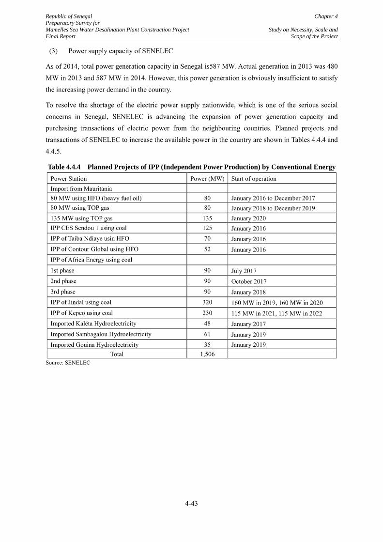
Republic of Senegal Chapter 4 Preparatory Survey for Mamelles Sea Water Desalination Plant Construction Project Study on Necessity, Scale and Final Report Scope of the Project
(3) Power supply capacity of SENELEC
As of 2014, total power generation capacity in Senegal is587 MW. Actual generation in 2013 was 480 MW in 2013 and 587 MW in 2014. However, this power generation is obviously insufficient to satisfy the increasing power demand in the country.
To resolve the shortage of the electric power supply nationwide, which is one of the serious social concerns in Senegal, SENELEC is advancing the expansion of power generation capacity and purchasing transactions of electric power from the neighbouring countries. Planned projects and transactions of SENELEC to increase the available power in the country are shown in Tables 4.4.4 and 4.4.5.
Table 4.4.4 Planned Projects of IPP (Independent Power Production) by Conventional Energy Power Station Power (MW) Start of operation Import from Mauritania 80 MW using HFO (heavy fuel oil) 80 January 2016 to December 2017 80 MW using TOP gas 80 January 2018 to December 2019 135 MW using TOP gas 135 January 2020 IPP CES Sendou 1 using coal 125 January 2016 IPP of Taiba Ndiaye usin HFO 70 January 2016 IPP of Contour Global using HFO 52 January 2016 IPP of Africa Energy using coal
1st phase 90 July 2017 2nd phase 90 October 2017 3rd phase 90 January 2018 IPP of Jindal using coal 320 160 MW in 2019, 160 MW in 2020 IPP of Kepco using coal 230 115 MW in 2021, 115 MW in 2022 Imported Kaléta Hydroelectricity 48 January 2017 Imported Sambagalou Hydroelectricity 61 January 2019 Imported Gouina Hydroelectricity 35 January 2019
Total 1,506
Source: SENELEC
4-43
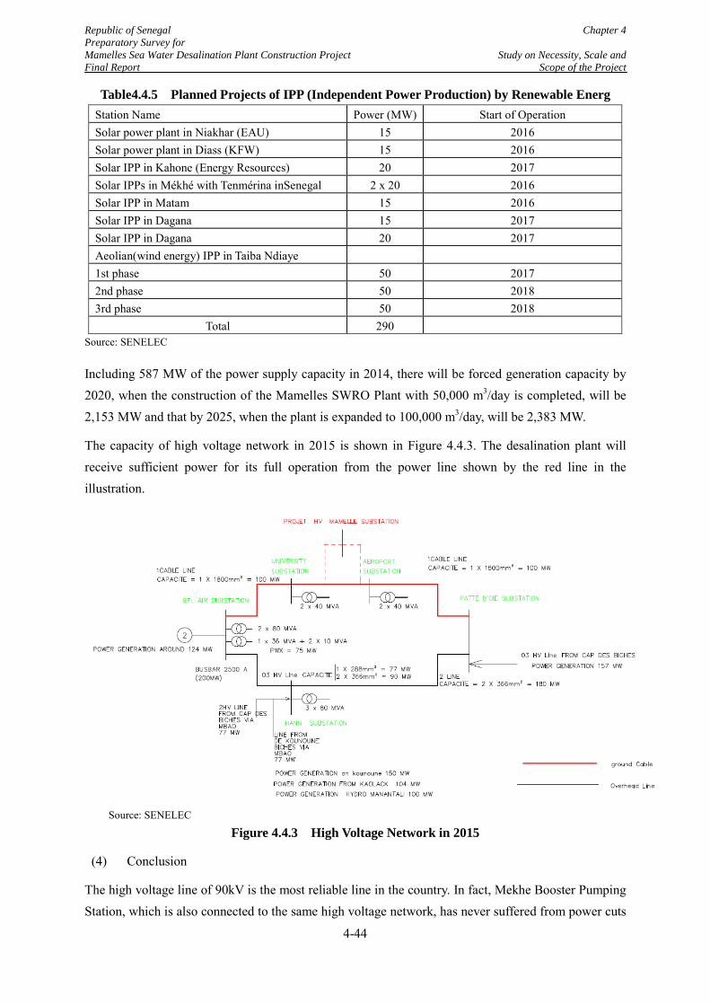
Republic of Senegal Chapter 4 Preparatory Survey for Mamelles Sea Water Desalination Plant Construction Project Study on Necessity, Scale and Final Report Scope of the Project
Table4.4.5 Planned Projects of IPP (Independent Power Production) by Renewable Energ Station Name Power (MW) Start of Operation Solar power plant in Niakhar (EAU) 15 2016 Solar power plant in Diass (KFW) 15 2016 Solar IPP in Kahone (Energy Resources) 20 2017 Solar IPPs in Mékhé with Tenmérina inSenegal 2 x 20 2016 Solar IPP in Matam 15 2016 Solar IPP in Dagana 15 2017 Solar IPP in Dagana 20 2017 Aeolian(wind energy) IPP in Taiba Ndiaye 1st phase 50 2017 2nd phase 50 2018 3rd phase 50 2018
Total 290 Source: SENELEC
Including 587 MW of the power supply capacity in 2014, there will be forced generation capacity by 2020, when the construction of the Mamelles SWRO Plant with 50,000 m3/day is completed, will be 2,153 MW and that by 2025, when the plant is expanded to 100,000 m3/day, will be 2,383 MW.
The capacity of high voltage network in 2015 is shown in Figure 4.4.3. The desalination plant will receive sufficient power for its full operation from the power line shown by the red line in the illustration.
Source: SENELEC
Figure 4.4.3 High Voltage Network in 2015
(4) Conclusion
The high voltage line of 90kV is the most reliable line in the country. In fact, Mekhe Booster Pumping Station, which is also connected to the same high voltage network, has never suffered from power cuts
4-44
Republic of Senegal Chapter 4 Preparatory Survey for Mamelles Sea Water Desalination Plant Construction Project Study on Necessity, Scale and Final Report Scope of the Project
since commencement of the operation in 2006. Power demand (13MVA) of the 50,000 m3/day plant from 2020 will be 0.6% of the expected national power capacity and that of the 100,000 m3/day plant from 2025 will be 1.1%. All planned projects of SENELEC will not be implemented as scheduled but the JICA Study Team believes that the plant has a high possibility of receiving a sufficient and stable power supply from the beginning of its operation.
4.4.5 Possible Environmental and Social Impacts and Acquisition of Environmental Certificate
Similar to all other infrastructure development projects, the Project may bring about both favourable and adverse impacts during the construction and operation phases. In order to assess such impacts and identify the mitigation measures, SONES is going to carry out an environmental impact assessment (EIA) study for the Project. The study report will be submitted to DEEC for the review and SONES expects that they will obtain an Environmental Compliance Certificate (ECC) from DEEC. According to M/M on February 12, 2015, SONES will start the EIA Study soon and will complete examination, if there are no obstacles for the implementation of the Project regarding EIA, by the time of submission of the final report of this Study, which is October 2015.
SONES plans to obtain the ECC by March 2016. However the commencement of the EIA study was delayed and the kick-off meeting between SONES and the consultant has just been held on 30th September, 2015. The overall procedure for the issuance of the ECC will be given in Section 6.7.
Possible adverse impacts and the mitigation measures will be carefully studied in the EIA Study by SONES. As an initial view, however, possible major adverse environmental and social impacts by the Project will be i) adverse impact on marine natural conditions by brine discharge from the seawater desalination, ii) noise and vibration from the seawater transmission pumping station which will be located near the operating hotel and iii) adverse impact on utilization of local use among the local fishermen and the recreation activities in the sea and beach where the seawater intake and brine discharge facilities and the seawater pumping station will be constructed. JICA Study Team considers that all such impacts would be mitigated or eliminated by careful design of the facilities and sufficient communications with the stakeholders, which will be done in the EIA Study by SONES.
More detailed information on the possible environmental and social impacts are given in Section 6.5.
As a conclusion of the discussions described in Subsections 4.4.1 to 4.4.5 above, JICA Study Team has confirmed validity of the planned construction site of the Mamelles SWRO Plant. Although there are important issues, especially regarding the construction permission, ECC, and land acquisition, SONES will be able to solve them to realize the Project.
4-45
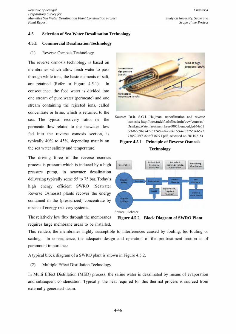
Republic of Senegal Chapter 4 Preparatory Survey for Mamelles Sea Water Desalination Plant Construction Project Study on Necessity, Scale and Final Report Scope of the Project
4.5 Selection of Sea Water Desalination Technology
4.5.1 Commercial Desalination Technology
(1) Reverse Osmosis Technology
The reverse osmosis technology is based on membranes which allow fresh water to pass through while ions, the basic elements of salt, are retained (Refer to Figure 4.5.1). In consequence, the feed water is divided into one stream of pure water (permeate) and one stream containing the rejected ions, called concentrate or brine, which is returned to the sea. The typical recovery ratio, i.e. the permeate flow related to the seawater flow fed into the reverse osmosis section, is typically 40% to 45%, depending mainly on the sea water salinity and temperature.
The driving force of the reverse osmosis process is pressure which is induced by a high pressure pump, in seawater desalination delivering typically some 55 to 75 bar. Today’s high energy efficient SWRO (Seawater Reverse Osmosis) plants recover the energy contained in the (pressurized) concentrate by means of energy recovery systems.
The relatively low flux through the membranes requires large membrane areas to be installed. This renders the membranes highly susceptible to interferences caused by fouling, bio-fouling or scaling. In consequence, the adequate design and operation of the pre-treatment section is of paramount importance.
A typical block diagram of a SWRO plant is shown in Figure 4.5.2.
(2) Multiple Effect Distillation Technology
In Multi Effect Distillation (MED) process, the saline water is desalinated by means of evaporation and subsequent condensation. Typically, the heat required for this thermal process is sourced from externally generated steam.
Source: Dr.ir. S.G.J. Heijman, nanofiltration and reverse osmosis; http://ocw.tudelft.nl/fileadmin/ocw/courses/ DrinkingWaterTreatment1/res00053/embedded/!4e616e6f66696c74726174696f6e20616e642072657665727365206f736d6f736973.pdf, accessed on 20110218)
Figure 4.5.1 Principle of Reverse Osmosis Technology
Source: Fichtner
Figure 4.5.2 Block Diagram of SWRO Plant
4-46
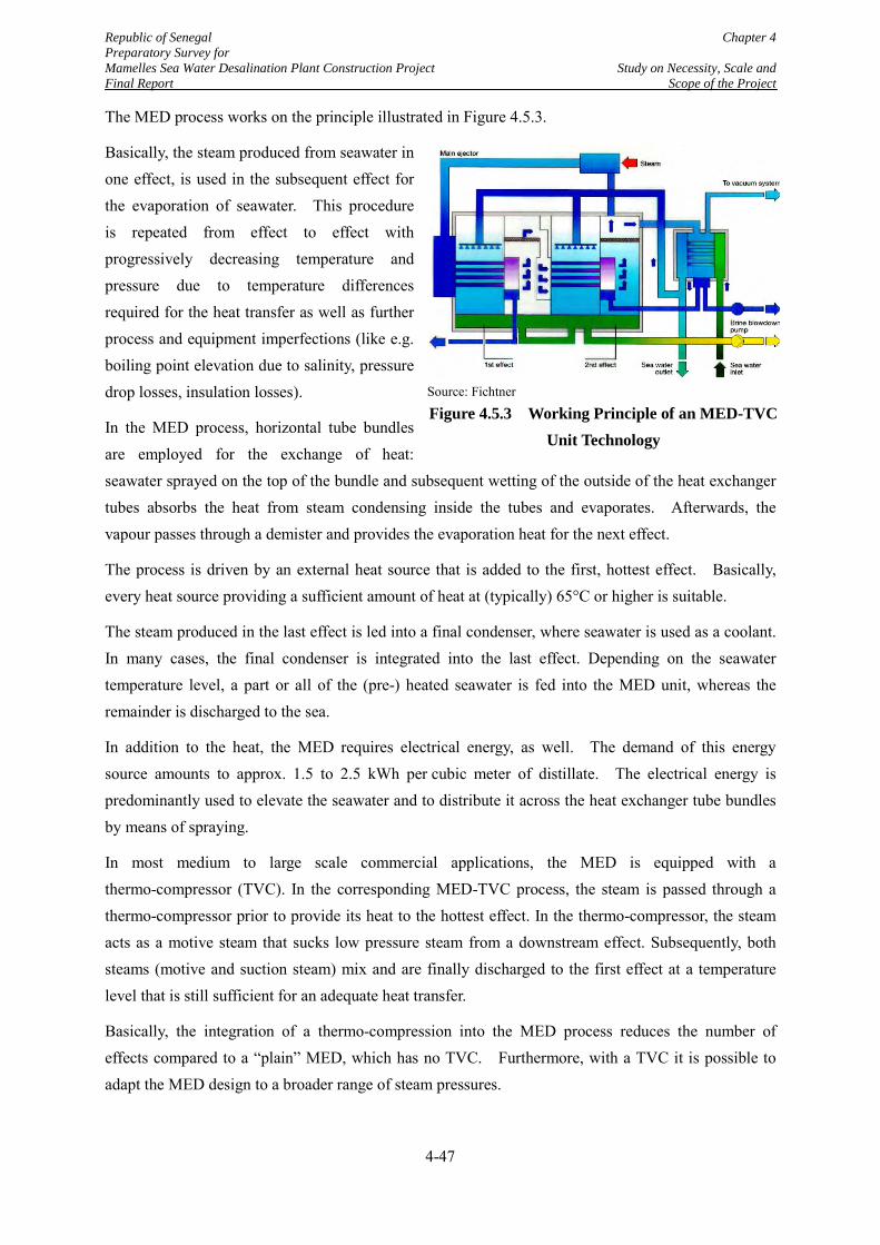
Republic of Senegal Chapter 4 Preparatory Survey for Mamelles Sea Water Desalination Plant Construction Project Study on Necessity, Scale and Final Report Scope of the Project
The MED process works on the principle illustrated in Figure 4.5.3.
Basically, the steam produced from seawater in one effect, is used in the subsequent effect for the evaporation of seawater. This procedure is repeated from effect to effect with progressively decreasing temperature and pressure due to temperature differences required for the heat transfer as well as further process and equipment imperfections (like e.g. boiling point elevation due to salinity, pressure drop losses, insulation losses).
In the MED process, horizontal tube bundles are employed for the exchange of heat: seawater sprayed on the top of the bundle and subsequent wetting of the outside of the heat exchanger tubes absorbs the heat from steam condensing inside the tubes and evaporates. Afterwards, the vapour passes through a demister and provides the evaporation heat for the next effect.
The process is driven by an external heat source that is added to the first, hottest effect. Basically, every heat source providing a sufficient amount of heat at (typically) 65°C or higher is suitable.
The steam produced in the last effect is led into a final condenser, where seawater is used as a coolant. In many cases, the final condenser is integrated into the last effect. Depending on the seawater temperature level, a part or all of the (pre-) heated seawater is fed into the MED unit, whereas the remainder is discharged to the sea.
In addition to the heat, the MED requires electrical energy, as well. The demand of this energy source amounts to approx. 1.5 to 2.5 kWh per cubic meter of distillate. The electrical energy is predominantly used to elevate the seawater and to distribute it across the heat exchanger tube bundles by means of spraying.
In most medium to large scale commercial applications, the MED is equipped with a thermo-compressor (TVC). In the corresponding MED-TVC process, the steam is passed through a thermo-compressor prior to provide its heat to the hottest effect. In the thermo-compressor, the steam acts as a motive steam that sucks low pressure steam from a downstream effect. Subsequently, both steams (motive and suction steam) mix and are finally discharged to the first effect at a temperature level that is still sufficient for an adequate heat transfer.
Basically, the integration of a thermo-compression into the MED process reduces the number of effects compared to a “plain” MED, which has no TVC. Furthermore, with a TVC it is possible to adapt the MED design to a broader range of steam pressures.
Source: Fichtner
Figure 4.5.3 Working Principle of an MED-TVC Unit Technology
4-47
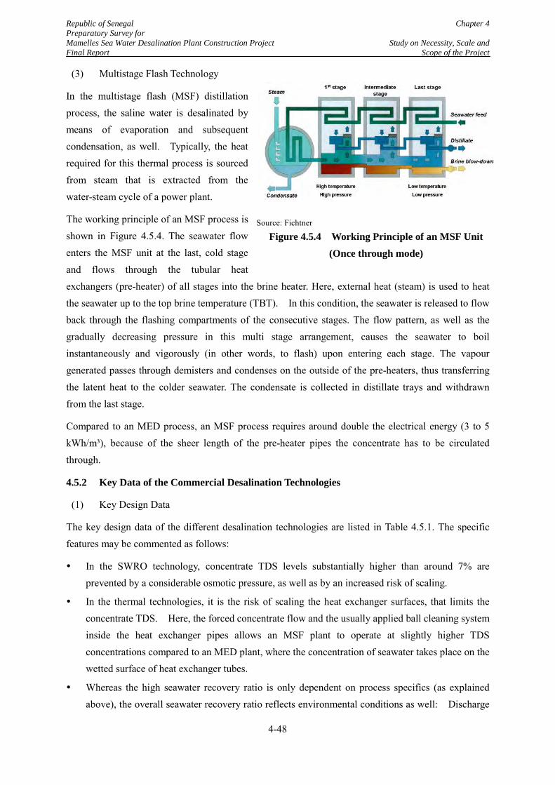
Republic of Senegal Chapter 4 Preparatory Survey for Mamelles Sea Water Desalination Plant Construction Project Study on Necessity, Scale and Final Report Scope of the Project
(3) Multistage Flash Technology
In the multistage flash (MSF) distillation process, the saline water is desalinated by means of evaporation and subsequent condensation, as well. Typically, the heat required for this thermal process is sourced from steam that is extracted from the water-steam cycle of a power plant.
The working principle of an MSF process is shown in Figure 4.5.4. The seawater flow enters the MSF unit at the last, cold stage and flows through the tubular heat exchangers (pre-heater) of all stages into the brine heater. Here, external heat (steam) is used to heat the seawater up to the top brine temperature (TBT). In this condition, the seawater is released to flow back through the flashing compartments of the consecutive stages. The flow pattern, as well as the gradually decreasing pressure in this multi stage arrangement, causes the seawater to boil instantaneously and vigorously (in other words, to flash) upon entering each stage. The vapour generated passes through demisters and condenses on the outside of the pre-heaters, thus transferring the latent heat to the colder seawater. The condensate is collected in distillate trays and withdrawn from the last stage.
Compared to an MED process, an MSF process requires around double the electrical energy (3 to 5 kWh/m³), because of the sheer length of the pre-heater pipes the concentrate has to be circulated through.
4.5.2 Key Data of the Commercial Desalination Technologies
(1) Key Design Data
The key design data of the different desalination technologies are listed in Table 4.5.1. The specific features may be commented as follows:
In the SWRO technology, concentrate TDS levels substantially higher than around 7% are prevented by a considerable osmotic pressure, as well as by an increased risk of scaling.
In the thermal technologies, it is the risk of scaling the heat exchanger surfaces, that limits the concentrate TDS. Here, the forced concentrate flow and the usually applied ball cleaning system inside the heat exchanger pipes allows an MSF plant to operate at slightly higher TDS concentrations compared to an MED plant, where the concentration of seawater takes place on the wetted surface of heat exchanger tubes.
Whereas the high seawater recovery ratio is only dependent on process specifics (as explained above), the overall seawater recovery ratio reflects environmental conditions as well: Discharge
Source: Fichtner
Figure 4.5.4 Working Principle of an MSF Unit (Once through mode)
4-48
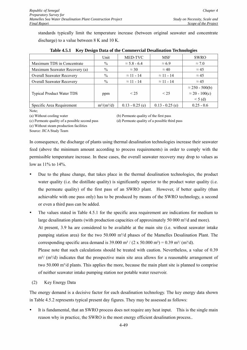
Republic of Senegal Chapter 4 Preparatory Survey for Mamelles Sea Water Desalination Plant Construction Project Study on Necessity, Scale and Final Report Scope of the Project
standards typically limit the temperature increase (between original seawater and concentrate discharge) to a value between 8 K and 10 K.
Table 4.5.1 Key Design Data of the Commercial Desalination Technologies Unit MED-TVC MSF SWRO Maximum TDS in Concentrate % ≈ 5.8 - 6.4 ≈ 6.9 ≈ 7.0 Maximum Seawater Recovery (a) % ≈ 30 ≈ 40 ≈ 45 Overall Seawater Recovery % ≈ 11 - 14 ≈ 11 - 14 ≈ 45 Overall Seawater Recovery % ≈ 11 - 14 ≈ 11 - 14 ≈ 45
Typical Product Water TDS ppm < 25 < 25 ≈ 250 - 500(b) ≈ 20 - 100(c)
< 5 (d) Specific Area Requirement m²/(m³/d) 0.13 - 0.25 (e) 0.13 - 0.25 (e) 0.25 - 0.6
Note; (a) Without cooling water (b) Permeate quality of the first pass (c) Permeate quality of a possible second pass (d) Permeate quality of a possible third pass (e) Without steam production facilities Source: JICA Study Team
In consequence, the discharge of plants using thermal desalination technologies increase their seawater feed (above the minimum amount according to process requirements) in order to comply with the permissible temperature increase. In these cases, the overall seawater recovery may drop to values as low as 11% to 14%.
Due to the phase change, that takes place in the thermal desalination technologies, the product water quality (i.e. the distillate quality) is significantly superior to the product water quality (i.e. the permeate quality) of the first pass of an SWRO plant. However, if better quality (than achievable with one pass only) has to be produced by means of the SWRO technology, a second or even a third pass can be added.
The values stated in Table 4.5.1 for the specific area requirement are indications for medium to large desalination plants (with production capacities of approximately 50 000 m³/d and more). At present, 3.9 ha are considered to be available at the main site (i.e. without seawater intake pumping station area) for the two 50.000 m³/d phases of the Mamelles Desalination Plant. The corresponding specific area demand is 39.000 m² / (2 x 50.000 m²) = 0.39 m²/ (m³/d). Please note that such calculations should be treated with caution. Nevertheless, a value of 0.39 m²/ (m³/d) indicates that the prospective main site area allows for a reasonable arrangement of two 50.000 m³/d plants. This applies the more, because the main plant site is planned to comprise of neither seawater intake pumping station nor potable water reservoir.
(2) Key Energy Data
The energy demand is a decisive factor for each desalination technology. The key energy data shown in Table 4.5.2 represents typical present day figures. They may be assessed as follows:
It is fundamental, that an SWRO process does not require any heat input. This is the single main reason why in practice, the SWRO is the most energy efficient desalination process..
4-49
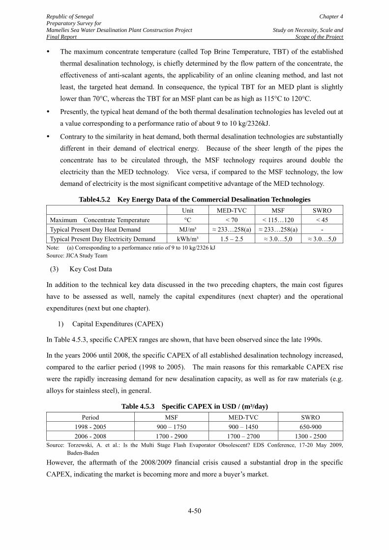
Republic of Senegal Chapter 4 Preparatory Survey for Mamelles Sea Water Desalination Plant Construction Project Study on Necessity, Scale and Final Report Scope of the Project
The maximum concentrate temperature (called Top Brine Temperature, TBT) of the established thermal desalination technology, is chiefly determined by the flow pattern of the concentrate, the effectiveness of anti-scalant agents, the applicability of an online cleaning method, and last not least, the targeted heat demand. In consequence, the typical TBT for an MED plant is slightly lower than 70°C, whereas the TBT for an MSF plant can be as high as 115°C to 120°C.
Presently, the typical heat demand of the both thermal desalination technologies has leveled out at a value corresponding to a performance ratio of about 9 to 10 kg/2326kJ.
Contrary to the similarity in heat demand, both thermal desalination technologies are substantially different in their demand of electrical energy. Because of the sheer length of the pipes the concentrate has to be circulated through, the MSF technology requires around double the electricity than the MED technology. Vice versa, if compared to the MSF technology, the low demand of electricity is the most significant competitive advantage of the MED technology.
Table4.5.2 Key Energy Data of the Commercial Desalination Technologies Unit MED-TVC MSF SWRO Maximum Concentrate Temperature °C < 70 < 115…120 < 45 Typical Present Day Heat Demand MJ/m³ ≈ 233…258(a) ≈ 233…258(a) - Typical Present Day Electricity Demand kWh/m³ 1.5 – 2.5 ≈ 3.0…5,0 ≈ 3.0…5,0
Note: (a) Corresponding to a performance ratio of 9 to 10 kg/2326 kJ Source: JICA Study Team
(3) Key Cost Data
In addition to the technical key data discussed in the two preceding chapters, the main cost figures have to be assessed as well, namely the capital expenditures (next chapter) and the operational expenditures (next but one chapter).
1) Capital Expenditures (CAPEX)
In Table 4.5.3, specific CAPEX ranges are shown, that have been observed since the late 1990s.
In the years 2006 until 2008, the specific CAPEX of all established desalination technology increased, compared to the earlier period (1998 to 2005). The main reasons for this remarkable CAPEX rise were the rapidly increasing demand for new desalination capacity, as well as for raw materials (e.g. alloys for stainless steel), in general.
Table 4.5.3 Specific CAPEX in USD / (m³/day) Period MSF MED-TVC SWRO
1998 - 2005 900 – 1750 900 – 1450 650-900 2006 - 2008 1700 - 2900 1700 – 2700 1300 - 2500
Source: Torzewski, A. et al.: Is the Multi Stage Flash Evaporator Obsolescent? EDS Conference, 17-20 May 2009, Baden-Baden
However, the aftermath of the 2008/2009 financial crisis caused a substantial drop in the specific CAPEX, indicating the market is becoming more and more a buyer’s market.
4-50
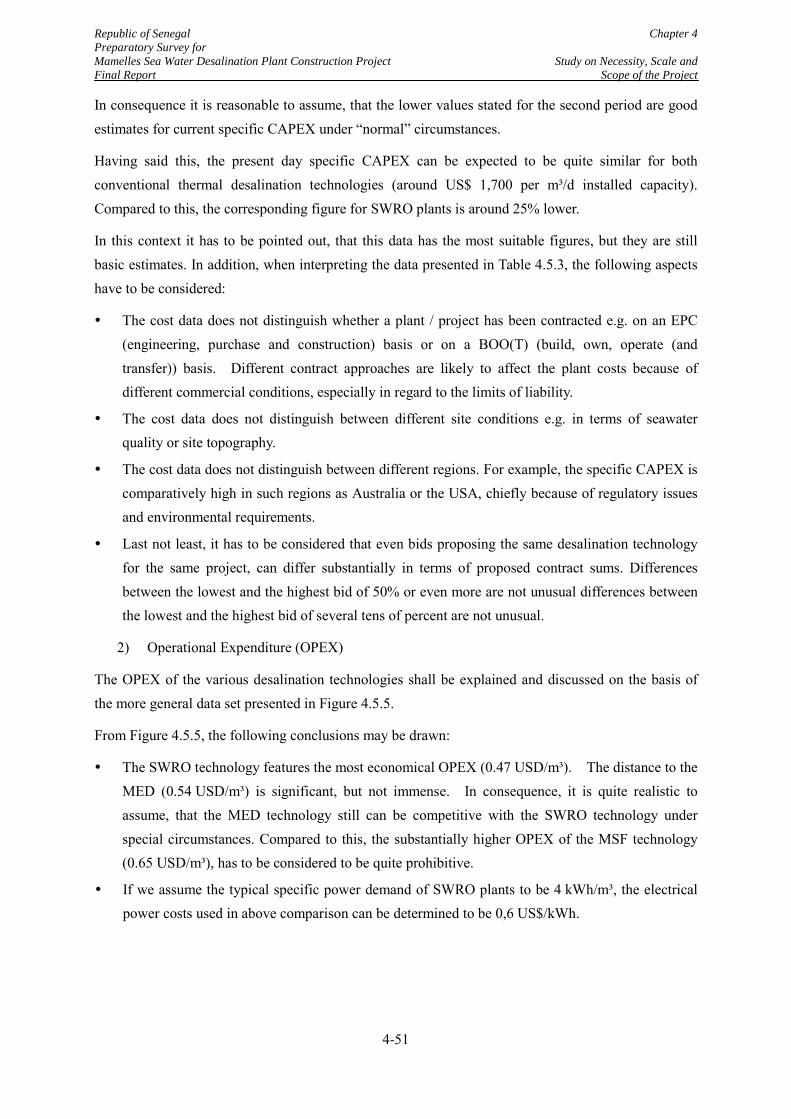
Republic of Senegal Chapter 4 Preparatory Survey for Mamelles Sea Water Desalination Plant Construction Project Study on Necessity, Scale and Final Report Scope of the Project
In consequence it is reasonable to assume, that the lower values stated for the second period are good estimates for current specific CAPEX under “normal” circumstances.
Having said this, the present day specific CAPEX can be expected to be quite similar for both conventional thermal desalination technologies (around US$ 1,700 per m³/d installed capacity). Compared to this, the corresponding figure for SWRO plants is around 25% lower.
In this context it has to be pointed out, that this data has the most suitable figures, but they are still basic estimates. In addition, when interpreting the data presented in Table 4.5.3, the following aspects have to be considered:
The cost data does not distinguish whether a plant / project has been contracted e.g. on an EPC (engineering, purchase and construction) basis or on a BOO(T) (build, own, operate (and transfer)) basis. Different contract approaches are likely to affect the plant costs because of different commercial conditions, especially in regard to the limits of liability.
The cost data does not distinguish between different site conditions e.g. in terms of seawater quality or site topography.
The cost data does not distinguish between different regions. For example, the specific CAPEX is comparatively high in such regions as Australia or the USA, chiefly because of regulatory issues and environmental requirements.
Last not least, it has to be considered that even bids proposing the same desalination technology for the same project, can differ substantially in terms of proposed contract sums. Differences between the lowest and the highest bid of 50% or even more are not unusual differences between the lowest and the highest bid of several tens of percent are not unusual.
2) Operational Expenditure (OPEX)
The OPEX of the various desalination technologies shall be explained and discussed on the basis of the more general data set presented in Figure 4.5.5.
From Figure 4.5.5, the following conclusions may be drawn:
The SWRO technology features the most economical OPEX (0.47 USD/m³). The distance to the MED (0.54 USD/m³) is significant, but not immense. In consequence, it is quite realistic to assume, that the MED technology still can be competitive with the SWRO technology under special circumstances. Compared to this, the substantially higher OPEX of the MSF technology (0.65 USD/m³), has to be considered to be quite prohibitive.
If we assume the typical specific power demand of SWRO plants to be 4 kWh/m³, the electrical power costs used in above comparison can be determined to be 0,6 US$/kWh.
4-51
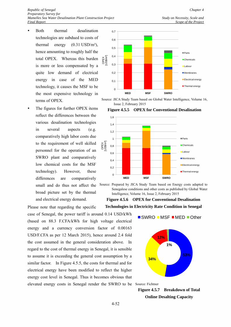
Republic of Senegal Chapter 4 Preparatory Survey for Mamelles Sea Water Desalination Plant Construction Project Study on Necessity, Scale and Final Report Scope of the Project
Both thermal desalination technologies are subdued to costs of thermal energy (0.31 USD/m³), hence amounting to roughly half the total OPEX. Whereas this burden is more or less compensated by a quite low demand of electrical energy in case of the MED technology, it causes the MSF to be the most expensive technology in terms of OPEX.
The figures for further OPEX items reflect the differences between the various desalination technologies in several aspects (e.g. comparatively high labor costs due to the requirement of well skilled personnel for the operation of an SWRO plant and comparatively low chemical costs for the MSF technology). However, these differences are comparatively small and do thus not affect the broad picture set by the thermal and electrical energy demand.
Please note that regarding the specific case of Senegal, the power tariff is around 0.14 USD/kWh (based on 88.3 F.CFA/kWh for high voltage electrical energy and a currency conversion factor of 0.00163 USD/F.CFA as per 12 March 2015), hence around 2.4 fold the cost assumed in the general consideration above. In regard to the cost of thermal energy in Senegal, it is sensible to assume it is exceeding the general cost assumption by a similar factor. In Figure 4.5.5, the costs for thermal and for electrical energy have been modified to reflect the higher energy cost level in Senegal. Thus it becomes obvious that elevated energy costs in Senegal render the SWRO to be
Source: JICA Study Team based on Global Water Intelligence, Volume 16,
Issue 2, February 2015
Figure 4.5.5 OPEX for Conventional Desalination Technologies in General Electricity Rate Condition
0
0,1
0,2
0,3
0,4
0,5
0,6
0,7
MED MSF SWRO
OP
EX
[US
$/m
³]
Parts
Chemicals
Labour
Membranes
Electrical energy
Thermal energy
Source: Fichtner
Figure 4.5.7 Breakdown of Total Online Desalting Capacity
53%34%
12%
1%
SWRO MSF MED Other
Source: Prepared by JICA Study Team based on Energy costs adapted to Senegalese conditions and other costs as published by Global Water Intelligence, Volume 16, Issue 2, February 2015
Figure 4.5.6 OPEX for Conventional Desalination Technologies in Electricity Rate Condition in Senegal
0
0,2
0,4
0,6
0,8
1
1,2
1,4
1,6
MED MSF SWRO
OPE
X[U
S$/m
³]
Parts
Chemicals
Labour
Membranes
Electrical energy
Thermal energy
4-52
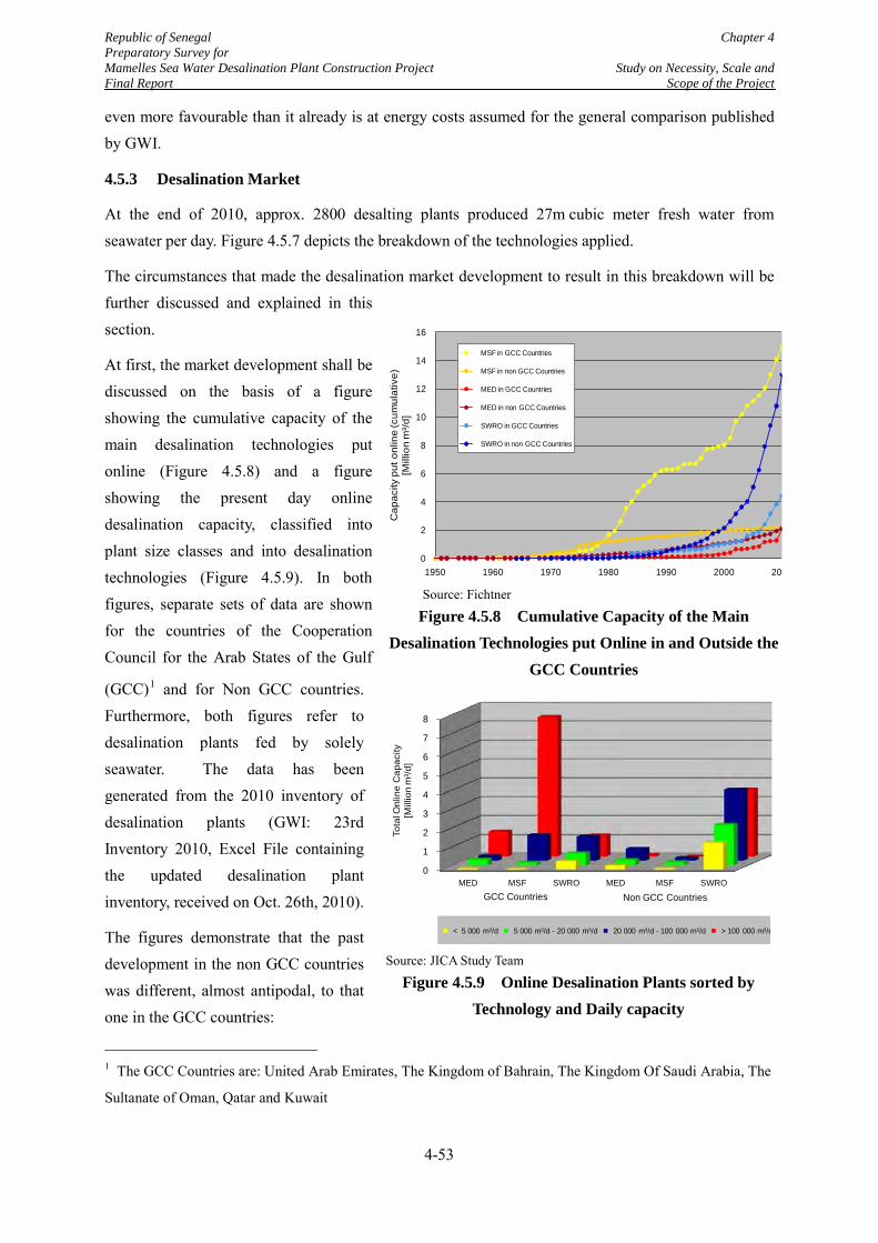
Republic of Senegal Chapter 4 Preparatory Survey for Mamelles Sea Water Desalination Plant Construction Project Study on Necessity, Scale and Final Report Scope of the Project
even more favourable than it already is at energy costs assumed for the general comparison published by GWI.
4.5.3 Desalination Market
At the end of 2010, approx. 2800 desalting plants produced 27m cubic meter fresh water from seawater per day. Figure 4.5.7 depicts the breakdown of the technologies applied.
The circumstances that made the desalination market development to result in this breakdown will be further discussed and explained in this section.
At first, the market development shall be discussed on the basis of a figure showing the cumulative capacity of the main desalination technologies put online (Figure 4.5.8) and a figure showing the present day online desalination capacity, classified into plant size classes and into desalination technologies (Figure 4.5.9). In both figures, separate sets of data are shown for the countries of the Cooperation Council for the Arab States of the Gulf
(GCC)1 and for Non GCC countries. Furthermore, both figures refer to desalination plants fed by solely seawater. The data has been generated from the 2010 inventory of desalination plants (GWI: 23rd Inventory 2010, Excel File containing the updated desalination plant inventory, received on Oct. 26th, 2010).
The figures demonstrate that the past development in the non GCC countries was different, almost antipodal, to that one in the GCC countries:
1 The GCC Countries are: United Arab Emirates, The Kingdom of Bahrain, The Kingdom Of Saudi Arabia, The
Sultanate of Oman, Qatar and Kuwait
Source: Fichtner
Figure 4.5.8 Cumulative Capacity of the Main Desalination Technologies put Online in and Outside the
GCC Countries
0
2
4
6
8
10
12
14
16
1950 1960 1970 1980 1990 2000 20
Cap
acity
put
onl
ine
(cum
ulat
ive)
[Mill
ion
m³/d
]
MSF in GCC Countries
MSF in non GCC Countries
MED in GCC Countries
MED in non GCC Countries
SWRO in GCC Countries
SWRO in non GCC Countries
Source: JICA Study Team
Figure 4.5.9 Online Desalination Plants sorted by Technology and Daily capacity
0
1
2
3
4
5
6
7
8
MED MSF SWRO MED MSF SWRO
Tota
l Onl
ine
Cap
acity
[Mill
ion
m³/d
]
Non GCC CountriesGCC Countries
< 5 000 m³/d 5 000 m³/d - 20 000 m³/d 20 000 m³/d - 100 000 m³/d > 100 000 m³/d
4-53
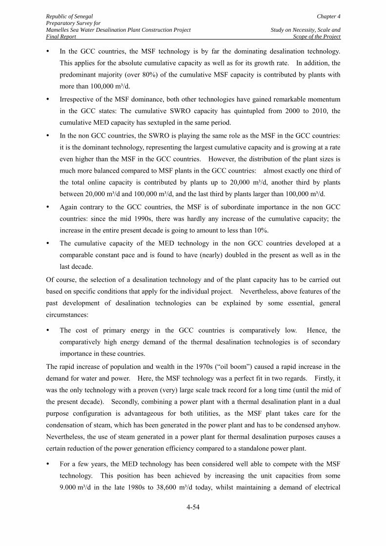
Republic of Senegal Chapter 4 Preparatory Survey for Mamelles Sea Water Desalination Plant Construction Project Study on Necessity, Scale and Final Report Scope of the Project
In the GCC countries, the MSF technology is by far the dominating desalination technology. This applies for the absolute cumulative capacity as well as for its growth rate. In addition, the predominant majority (over 80%) of the cumulative MSF capacity is contributed by plants with more than 100,000 m³/d.
Irrespective of the MSF dominance, both other technologies have gained remarkable momentum in the GCC states: The cumulative SWRO capacity has quintupled from 2000 to 2010, the cumulative MED capacity has sextupled in the same period.
In the non GCC countries, the SWRO is playing the same role as the MSF in the GCC countries: it is the dominant technology, representing the largest cumulative capacity and is growing at a rate even higher than the MSF in the GCC countries. However, the distribution of the plant sizes is much more balanced compared to MSF plants in the GCC countries: almost exactly one third of the total online capacity is contributed by plants up to 20,000 m³/d, another third by plants between 20,000 m³/d and 100,000 m³/d, and the last third by plants larger than 100,000 m³/d.
Again contrary to the GCC countries, the MSF is of subordinate importance in the non GCC countries: since the mid 1990s, there was hardly any increase of the cumulative capacity; the increase in the entire present decade is going to amount to less than 10%.
The cumulative capacity of the MED technology in the non GCC countries developed at a comparable constant pace and is found to have (nearly) doubled in the present as well as in the last decade.
Of course, the selection of a desalination technology and of the plant capacity has to be carried out based on specific conditions that apply for the individual project. Nevertheless, above features of the past development of desalination technologies can be explained by some essential, general circumstances:
The cost of primary energy in the GCC countries is comparatively low. Hence, the comparatively high energy demand of the thermal desalination technologies is of secondary importance in these countries.
The rapid increase of population and wealth in the 1970s (“oil boom”) caused a rapid increase in the demand for water and power. Here, the MSF technology was a perfect fit in two regards. Firstly, it was the only technology with a proven (very) large scale track record for a long time (until the mid of the present decade). Secondly, combining a power plant with a thermal desalination plant in a dual purpose configuration is advantageous for both utilities, as the MSF plant takes care for the condensation of steam, which has been generated in the power plant and has to be condensed anyhow. Nevertheless, the use of steam generated in a power plant for thermal desalination purposes causes a certain reduction of the power generation efficiency compared to a standalone power plant.
For a few years, the MED technology has been considered well able to compete with the MSF technology. This position has been achieved by increasing the unit capacities from some 9.000 m³/d in the late 1980s to 38,600 m³/d today, whilst maintaining a demand of electrical
4-54
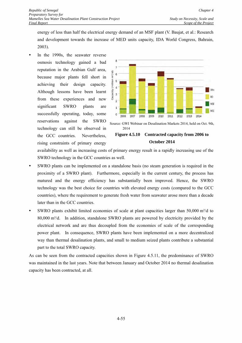
Republic of Senegal Chapter 4 Preparatory Survey for Mamelles Sea Water Desalination Plant Construction Project Study on Necessity, Scale and Final Report Scope of the Project
energy of less than half the electrical energy demand of an MSF plant (V. Baujat, et al.: Research and development towards the increase of MED units capacity, IDA World Congress, Bahrain, 2003).
In the 1990s, the seawater reverse osmosis technology gained a bad reputation in the Arabian Gulf area, because major plants fell short in achieving their design capacity. Although lessons have been learnt from these experiences and new significant SWRO plants are successfully operating, today, some reservations against the SWRO technology can still be observed in the GCC countries. Nevertheless, rising constraints of primary energy availability as well as increasing costs of primary energy result in a rapidly increasing use of the SWRO technology in the GCC countries as well.
SWRO plants can be implemented on a standalone basis (no steam generation is required in the proximity of a SWRO plant). Furthermore, especially in the current century, the process has matured and the energy efficiency has substantially been improved. Hence, the SWRO technology was the best choice for countries with elevated energy costs (compared to the GCC countries), where the requirement to generate fresh water from seawater arose more than a decade later than in the GCC countries.
SWRO plants exhibit limited economies of scale at plant capacities larger than 50,000 m³/d to 80,000 m³/d. In addition, standalone SWRO plants are powered by electricity provided by the electrical network and are thus decoupled from the economies of scale of the corresponding power plant. In consequence, SWRO plants have been implemented on a more decentralized way than thermal desalination plants, and small to medium seized plants contribute a substantial part to the total SWRO capacity.
As can be seen from the contracted capacities shown in Figure 4.5.11, the predominance of SWRO was maintained in the last years. Note that between January and October 2014 no thermal desalination capacity has been contracted, at all.
Source: GWI Webinar on Desalination Markets 2014, held on Oct. 9th,
2014
Figure 4.5.10 Contracted capacity from 2006 to October 2014
4-55
Republic of Senegal Chapter 4 Preparatory Survey for Mamelles Sea Water Desalination Plant Construction Project Study on Necessity, Scale and Final Report Scope of the Project
4.5.4 Conclusions
For the Mamelles Desalination Plant, the following conclusions can be drawn:
Seawater Reverse Osmosis is the most energy efficient technology, if you take electrical and thermal energy into account. Compared to a more global view on desalination, for Senegal this is the most obvious decision as energy is comparatively expensive.
Seawater Reverse Osmosis plants feature the lowest operational expenditures.
Neither MED nor MSF offer lower capital expenditures.
For using MED or MSF, it would be necessary to produce steam on site. In consequence there would be exhaust gas emissions, the demand for a considerable amount of cooling water and a temperature increase at the point of discharge of typically 8 K.
If MED or MSF is applied, the plant discharge would be an open discharge due to the amount of cooling water needed. This would cost a substantial part of the beach to be dedicated for industrial use (instead for recreational purposes).
At present there are no site specific indications known, which are against a SWRO. In particular, the area considered for placing the main plant of both phases can be considered to be sufficient, for the time being.
In summary, the SWRO is considered to be the most suitable technology because of its efficiency regarding energy demand and costs as well as because of unfavourable environmental impacts the thermal technologies would cause.
4-56
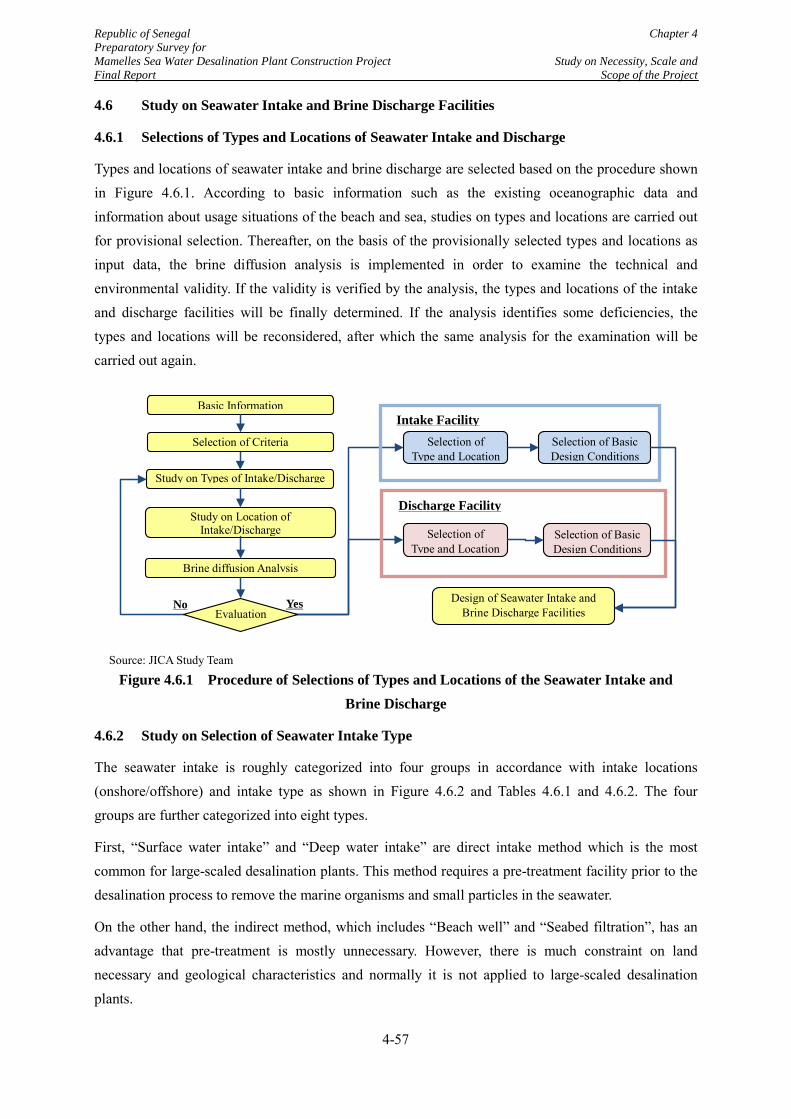
Republic of Senegal Chapter 4 Preparatory Survey for Mamelles Sea Water Desalination Plant Construction Project Study on Necessity, Scale and Final Report Scope of the Project
4.6 Study on Seawater Intake and Brine Discharge Facilities
4.6.1 Selections of Types and Locations of Seawater Intake and Discharge
Types and locations of seawater intake and brine discharge are selected based on the procedure shown in Figure 4.6.1. According to basic information such as the existing oceanographic data and information about usage situations of the beach and sea, studies on types and locations are carried out for provisional selection. Thereafter, on the basis of the provisionally selected types and locations as input data, the brine diffusion analysis is implemented in order to examine the technical and environmental validity. If the validity is verified by the analysis, the types and locations of the intake and discharge facilities will be finally determined. If the analysis identifies some deficiencies, the types and locations will be reconsidered, after which the same analysis for the examination will be carried out again.
Source: JICA Study Team
Figure 4.6.1 Procedure of Selections of Types and Locations of the Seawater Intake and Brine Discharge
4.6.2 Study on Selection of Seawater Intake Type
The seawater intake is roughly categorized into four groups in accordance with intake locations (onshore/offshore) and intake type as shown in Figure 4.6.2 and Tables 4.6.1 and 4.6.2. The four groups are further categorized into eight types.
First, “Surface water intake” and “Deep water intake” are direct intake method which is the most common for large-scaled desalination plants. This method requires a pre-treatment facility prior to the desalination process to remove the marine organisms and small particles in the seawater.
On the other hand, the indirect method, which includes “Beach well” and “Seabed filtration”, has an advantage that pre-treatment is mostly unnecessary. However, there is much constraint on land necessary and geological characteristics and normally it is not applied to large-scaled desalination plants.
Study on Types of Intake/Discharge
Study on Location of Intake/Discharge
Brine diffusion Analysis
Selection of Criteria
Basic Information
Selection of Basic Design Conditions
Selection of Basic Design Conditions
Selection of Type and Location
Selection of Type and Location
Design of Seawater Intake and Brine Discharge Facilities
Intake Facility
Discharge Facility
Yes No Evaluation
4-57
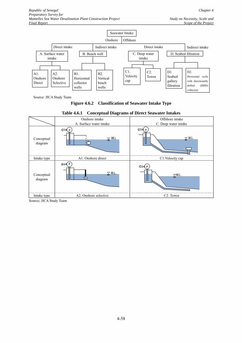
Republic of Senegal Chapter 4 Preparatory Survey for Mamelles Sea Water Desalination Plant Construction Project Study on Necessity, Scale and Final Report Scope of the Project
Source: JICA Study Team
Figure 4.6.2 Classification of Seawater Intake Type
Table 4.6.1 Conceptual Diagrams of Direct Seawater Intakes
Onshore intake Offshore intake A. Surface water intake C. Deep water intake
Conceptual diagram
Intake type A1. Onshore direct C1.Velocity cap
Conceptual diagram
Intake type A2. Onshore selective C2. Tower Source; JICA Study Team
Seawater Intake
A. Surface water intake
A1. Onshore Direct
A2. Onshore Selective
D1 Seabed gallery filtration
D. Seabed filtration
Indirect intake
B2. Vertical beach wells
B1. Horizontal collector wells
B. Beach well C. Deep water intake
C1. Velocity cap
C2. Tower
Direct intake
Onshore Offshore
Direct intake Indirect intake
D2. Horizontal wells with directionally drilled (HDD) collectors
W.L.
P
W.L
P
W.L.
P
W.L.
P
4-58
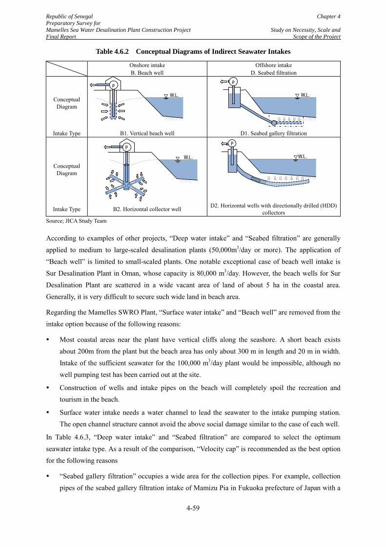
Republic of Senegal Chapter 4 Preparatory Survey for Mamelles Sea Water Desalination Plant Construction Project Study on Necessity, Scale and Final Report Scope of the Project
Table 4.6.2 Conceptual Diagrams of Indirect Seawater Intakes
Onshore intake Offshore intake B. Beach well D. Seabed filtration
Conceptual Diagram
Intake Type B1. Vertical beach well D1. Seabed gallery filtration
Conceptual Diagram
Intake Type B2. Horizontal collector well D2. Horizontal wells with directionally drilled (HDD) collectors
Source; JICA Study Team
According to examples of other projects, “Deep water intake” and “Seabed filtration” are generally applied to medium to large-scaled desalination plants (50,000m3/day or more). The application of “Beach well” is limited to small-scaled plants. One notable exceptional case of beach well intake is Sur Desalination Plant in Oman, whose capacity is 80,000 m3/day. However, the beach wells for Sur Desalination Plant are scattered in a wide vacant area of land of about 5 ha in the coastal area. Generally, it is very difficult to secure such wide land in beach area.
Regarding the Mamelles SWRO Plant, “Surface water intake” and “Beach well” are removed from the intake option because of the following reasons:
Most coastal areas near the plant have vertical cliffs along the seashore. A short beach exists about 200m from the plant but the beach area has only about 300 m in length and 20 m in width. Intake of the sufficient seawater for the 100,000 m3/day plant would be impossible, although no well pumping test has been carried out at the site.
Construction of wells and intake pipes on the beach will completely spoil the recreation and tourism in the beach.
Surface water intake needs a water channel to lead the seawater to the intake pumping station. The open channel structure cannot avoid the above social damage similar to the case of each well.
In Table 4.6.3, “Deep water intake” and “Seabed filtration” are compared to select the optimum seawater intake type. As a result of the comparison, “Velocity cap” is recommended as the best option for the following reasons
“Seabed gallery filtration” occupies a wide area for the collection pipes. For example, collection pipes of the seabed gallery filtration intake of Mamizu Pia in Fukuoka prefecture of Japan with a
W.L. P
W.L.
P
P
W.L. W.L. P
P
4-59
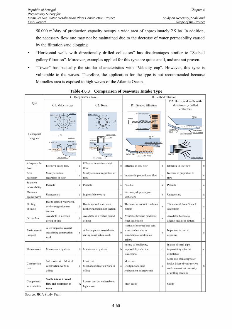
Republic of Senegal Chapter 4 Preparatory Survey for Mamelles Sea Water Desalination Plant Construction Project Study on Necessity, Scale and Final Report Scope of the Project
50,000 m3/day of production capacity occupy a wide area of approximately 2.9 ha. In addition, the necessary flow rate may not be maintained due to the decrease of water permeability caused by the filtration sand clogging.
“Horizontal wells with directionally drilled collectors” has disadvantages similar to “Seabed gallery filtration”. Moreover, examples applied for this type are quite small, and are not proven.
“Tower” has basically the similar characteristics with “Velocity cap”. However, this type is vulnerable to the waves. Therefore, the application for the type is not recommended because Mamelles area is exposed to high waves of the Atlantic Ocean.
Table 4.6.3 Comparison of Seawater Intake Type
Type
C. Deep water intake D. Seabed filtration
C1. Velocity cap C2. Tower D1. Seabed filtration D2. Horizontal wells with
directionally drilled collectors
Conceptual diagram
Adequacy for
flow Effective in any flow a
Effective in relatively high
flow b Effective in low flow b Effective in low flow b
Area
necessary
Mostly constant
regardless of flow a
Mostly constant regardless of
flow a Increase in proportion to flow c
Increase in proportion to
flow c
Selective
intake ability Possible a Possible a Possible a Possible a
Measures
against wave Unnecessary a Impressible to wave c
Necessary depending on
seabottom b Unnecessary a
Drifting
obstacle
Due to opened water area,
neither stagnation nor
suction
b Due to opened water area,
neither stagnation nor suction b
The material doesn’t reach sea
bottom a
The material doesn’t reach
sea bottom a
Oil outflow Avoidable in a certain
period of time b
Avoidable in a certain period
of time b
Avoidable because oil doesn’t
reach sea bottom a
Avoidable because oil
doesn’t reach sea bottom a
Environmenta
l impact
A few impact at coastal
area during construction
work
a A few impact at coastal area
during construction work b
Habitat of seaweed and coral
is encroached due to
installation of infiltration
gallery
c Impact on terrestrial
organism c
Maintenance Maintenance by diver b Maintenance by diver b
In case of small pipe,
impossibility after the
installation
c
In case of small pipe,
impossibility after the
installation
c
Construction
cost
2nd least cost. Most of
construction work in
offing
a
Least cost.
Most of construction work in
offing
a
Most cost.
Dredging and sand
replacement in large scale
c
More cost than deepwater
intake. Most of construction
work in coast but necessity
of drilling machine
b
Comprehensi
ve evaluation
Stable intake in small
flow and no impact of
wave
A Lowest cost but vulnerable to
high waves. - Most costly - Costly -
Source; JICA Study Team
SCREE
VELOCITY CAP
LOWER DECK
SCREEN VELOCITY CAP
W.L.
PIPE or TUNNEL
Surface layer
Middle layer
Bottom layer
INTAKE TOWER
INTAKE TOWER W.L.
PIPE or TUNNEL
Surface layer
Middle layer
Bottom layer
INFILTRATION GALLERY
PUMP PIT INTAKE PIPE
COLLECTION PIPES
W.L.
COLLECTING PIPES
INFILTRATION GALLERY REPLACED SAND
INTAKE PIPE
W.L.
COASTAL AQUIFER
HORIZONTAL WELLS
PRE-PACKED WELL SCREEN
PUMP PIT
HORIZONTAL WELLS
4-60
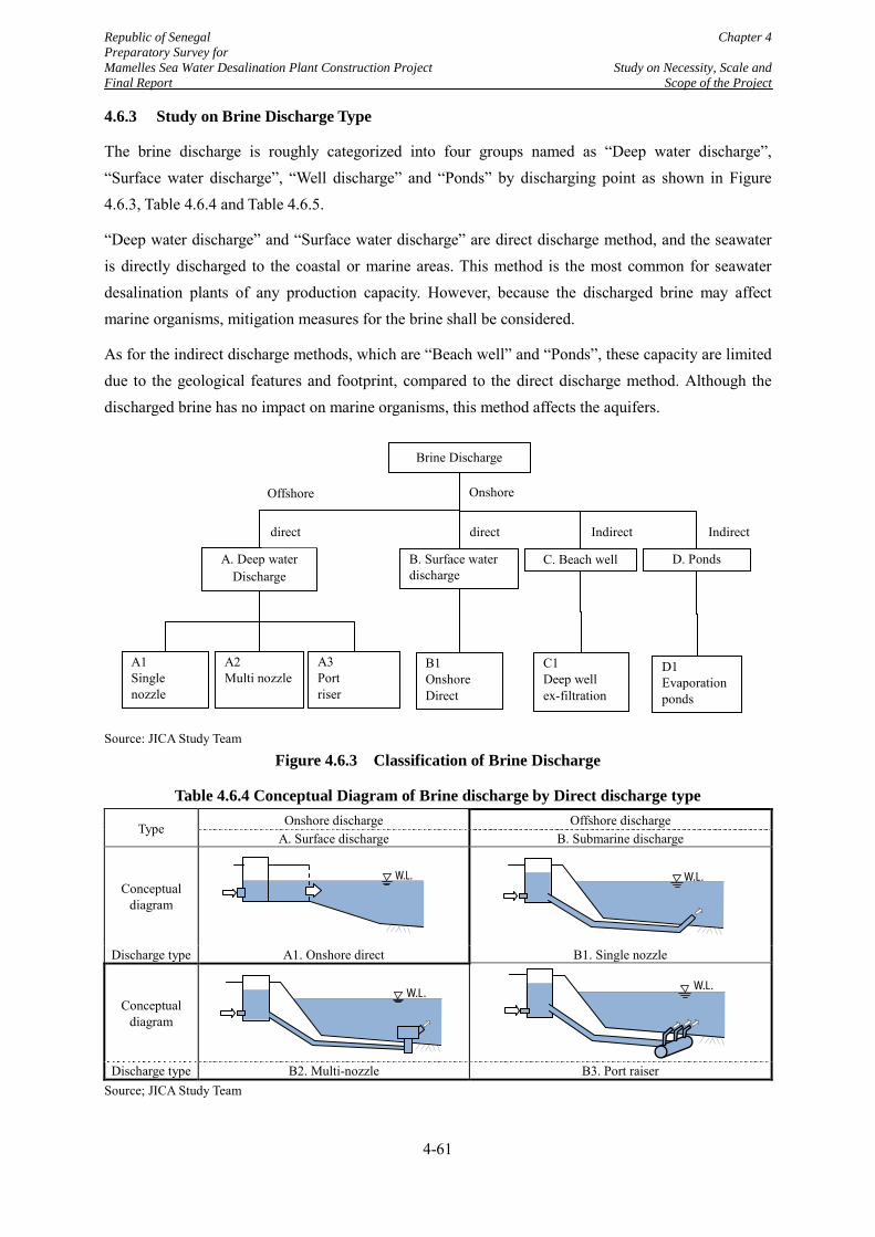
Republic of Senegal Chapter 4 Preparatory Survey for Mamelles Sea Water Desalination Plant Construction Project Study on Necessity, Scale and Final Report Scope of the Project
4.6.3 Study on Brine Discharge Type
The brine discharge is roughly categorized into four groups named as “Deep water discharge”, “Surface water discharge”, “Well discharge” and “Ponds” by discharging point as shown in Figure 4.6.3, Table 4.6.4 and Table 4.6.5.
“Deep water discharge” and “Surface water discharge” are direct discharge method, and the seawater is directly discharged to the coastal or marine areas. This method is the most common for seawater desalination plants of any production capacity. However, because the discharged brine may affect marine organisms, mitigation measures for the brine shall be considered.
As for the indirect discharge methods, which are “Beach well” and “Ponds”, these capacity are limited due to the geological features and footprint, compared to the direct discharge method. Although the discharged brine has no impact on marine organisms, this method affects the aquifers.
Source: JICA Study Team
Figure 4.6.3 Classification of Brine Discharge
Table 4.6.4 Conceptual Diagram of Brine discharge by Direct discharge type
Type Onshore discharge Offshore discharge A. Surface discharge B. Submarine discharge
Conceptual diagram
Discharge type A1. Onshore direct B1. Single nozzle
Conceptual diagram
Discharge type B2. Multi-nozzle B3. Port raiser Source; JICA Study Team
D1 Evaporation ponds
Brine Discharge
B. Surface water discharge
A. Deep water Discharge
C. Beach well D. Ponds
C1 Deep well ex-filtration
B1 Onshore Direct
A1 Single nozzle
A2 Multi nozzle
A3 Port riser
Offshore Onshore
Indirect Indirect direct direct
W.L.
W.L. W.L.
W.L.
4-61
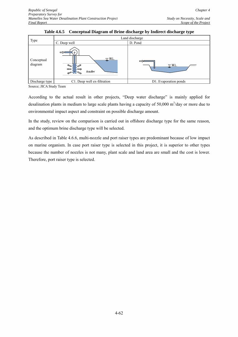
Republic of Senegal Chapter 4 Preparatory Survey for Mamelles Sea Water Desalination Plant Construction Project Study on Necessity, Scale and Final Report Scope of the Project
Table 4.6.5 Conceptual Diagram of Brine discharge by Indirect discharge type
Type Land discharge C. Deep well D. Pond
Conceptual diagram
Discharge type C1. Deep well ex-filtration D1. Evaporation ponds Source; JICA Study Team
According to the actual result in other projects, “Deep water discharge” is mainly applied for desalination plants in medium to large scale plants having a capacity of 50,000 m3/day or more due to environmental impact aspect and constraint on possible discharge amount.
In the study, review on the comparison is carried out in offshore discharge type for the same reason, and the optimum brine discharge type will be selected.
As described in Table 4.6.6, multi-nozzle and port raiser types are predominant because of low impact on marine organism. In case port raiser type is selected in this project, it is superior to other types because the number of nozzles is not many, plant scale and land area are small and the cost is lower. Therefore, port raiser type is selected.
W.L.
W.L. P
Aquifer
4-62
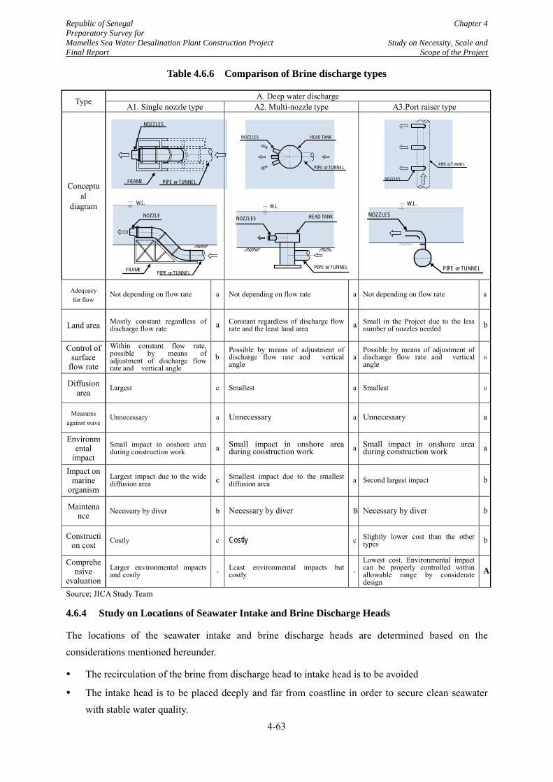
Republic of Senegal Chapter 4 Preparatory Survey for Mamelles Sea Water Desalination Plant Construction Project Study on Necessity, Scale and Final Report Scope of the Project
Table 4.6.6 Comparison of Brine discharge types
Source; JICA Study Team
4.6.4 Study on Locations of Seawater Intake and Brine Discharge Heads
The locations of the seawater intake and brine discharge heads are determined based on the considerations mentioned hereunder.
The recirculation of the brine from discharge head to intake head is to be avoided
The intake head is to be placed deeply and far from coastline in order to secure clean seawater with stable water quality.
Type A. Deep water discharge A1. Single nozzle type A2. Multi-nozzle type A3.Port raiser type
Conceptual
diagram
Adequacy for flow Not depending on flow rate a Not depending on flow rate a Not depending on flow rate a
Land area Mostly constant regardless of discharge flow rate a Constant regardless of discharge flow
rate and the least land area a Small in the Project due to the less number of nozzles needed b
Control of surface
flow rate
Within constant flow rate, possible by means of adjustment of discharge flow rate and vertical angle
b Possible by means of adjustment of discharge flow rate and vertical angle
a Possible by means of adjustment of discharge flow rate and vertical angle
a
Diffusion area Largest c Smallest a Smallest a
Measures against wave Unnecessary a Unnecessary a Unnecessary a
Environmental
impact Small impact in onshore area during construction work a Small impact in onshore area
during construction work a Small impact in onshore area during construction work a
Impact on marine
organism Largest impact due to the wide diffusion area c Smallest impact due to the smallest
diffusion area a Second largest impact b
Maintenance Necessary by diver b Necessary by diver B Necessary by diver b
Construction cost Costly c Costly c Slightly lower cost than the other
types b
Comprehensive
evaluation Larger environmental impacts and costly - Least environmental impacts but
costly - Lowest cost. Environmental impact can be properly controlled within allowable range by considerate design
A
PIPE or TUNNEL
NOZZLES
FRAME
FRAME
W.L.
NOZZLE
PIPE or TUNNEL
PIPE or TUNNEL
HEAD TANK NOZZLES
HEAD TANK
W.L
NOZZLES
PIPE or TUNNEL
PIPE or TUNNEL
NOZZLES
W.L.
NOZZLES
PIPE or TUNNEL
4-63
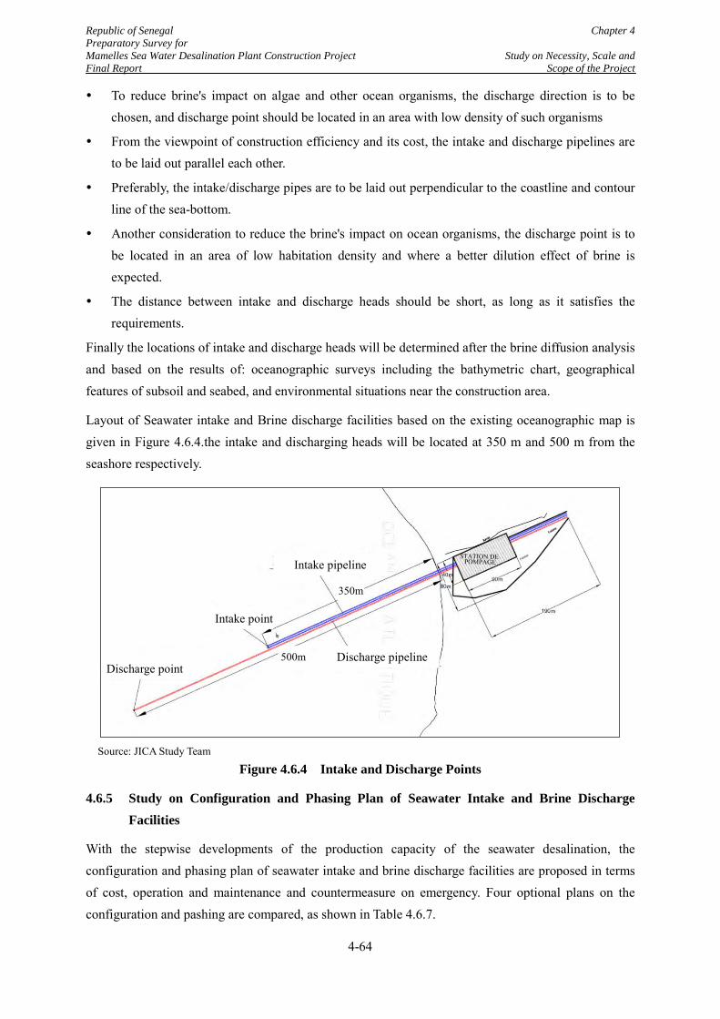
Republic of Senegal Chapter 4 Preparatory Survey for Mamelles Sea Water Desalination Plant Construction Project Study on Necessity, Scale and Final Report Scope of the Project
To reduce brine's impact on algae and other ocean organisms, the discharge direction is to be chosen, and discharge point should be located in an area with low density of such organisms
From the viewpoint of construction efficiency and its cost, the intake and discharge pipelines are to be laid out parallel each other.
Preferably, the intake/discharge pipes are to be laid out perpendicular to the coastline and contour line of the sea-bottom.
Another consideration to reduce the brine's impact on ocean organisms, the discharge point is to be located in an area of low habitation density and where a better dilution effect of brine is expected.
The distance between intake and discharge heads should be short, as long as it satisfies the requirements.
Finally the locations of intake and discharge heads will be determined after the brine diffusion analysis and based on the results of: oceanographic surveys including the bathymetric chart, geographical features of subsoil and seabed, and environmental situations near the construction area.
Layout of Seawater intake and Brine discharge facilities based on the existing oceanographic map is given in Figure 4.6.4.the intake and discharging heads will be located at 350 m and 500 m from the seashore respectively.
Source: JICA Study Team
Figure 4.6.4 Intake and Discharge Points
4.6.5 Study on Configuration and Phasing Plan of Seawater Intake and Brine Discharge Facilities
With the stepwise developments of the production capacity of the seawater desalination, the configuration and phasing plan of seawater intake and brine discharge facilities are proposed in terms of cost, operation and maintenance and countermeasure on emergency. Four optional plans on the configuration and pashing are compared, as shown in Table 4.6.7.
350m
500m Discharge pipeline
Intake point
Discharge point
Intake pipeline
4-64

Republic of Senegal Chapter 4 Preparatory Survey for Mamelles Sea Water Desalination Plant Construction Project Study on Necessity, Scale and Final Report Scope of the Project
As a result of comprehensive evaluation explained in Table 4.6.7, option No.4 is recommended. With this option, the seawater intake will be separated into two units so that any accidents or maintenance work will not completely result in suspension of the desalination plant, and it does not need any additional marine construction work in the future to expand the desalination plant.
4-65
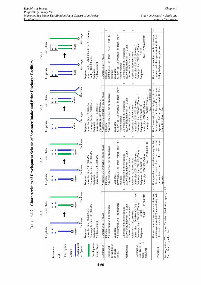
Republic of Senegal Chapter 4 Preparatory Survey for Mamelles Sea Water Desalination Plant Construction Project Study on Necessity, Scale and Final Report Scope of the Project
p
g
Rec
over
y ra
tion:
50%
, I
ntak
e C
apac
ity =
Pro
duct
ion
capa
city
/ 0.
5
A:e
xcel
lent
, b: g
ood,
c: f
air
N
o.1
No.
2 N
o.3
No.
4
Sche
mat
ic
and
Dev
elop
men
t
Sche
me
1st p
hase
2nd
phas
e
1s
t pha
se
Inta
ke F
acili
ty :
200,
000m
3/s
Dis
char
ge F
acili
ty: 1
00,0
00m
3/s
2nd
phas
e N
o de
velo
pmen
t
1st p
hase
2nd
phas
e
1s
t pha
se
Inta
ke F
acili
ty: 2
00,0
00m
3/s
Dis
char
ge F
acili
ty: 1
00,0
00m
3/s
2nd
phas
e In
take
Fac
ility
: 200
,000
m3/
s
1st p
hase
2nd
phas
e
1s
t pha
se
Inta
ke F
acili
ty:1
00,0
00m
3/s
Dis
char
ge F
acili
ty :5
0,00
0m3/
s 2n
d ph
ase
Inta
ke F
acili
ty:1
00,0
00m
3/s
Dis
char
ge F
acili
ty :5
0,00
0m3/
s
1st p
hase
2nd
phas
e
1s
t pha
se
Inta
ke F
acili
ty -
100,
000m
3/s
x 2
Dis
char
ge
Faci
lity:
100
,000
m3/
s 2n
d ph
ase
No
deve
lopm
ent
Con
stru
ctio
n C
ompl
etio
n at
1st
pha
se
N
eces
sity
of c
onst
ruct
ion
at 2
nd p
hase
Nec
essi
ty o
f con
stru
ctio
n at
2nd
pha
se
C
ompl
etio
n at
1st
pha
se
Ope
ratio
nal
diffi
culti
es o
f an
inta
ke
faci
lity
1st p
hase
N
o fr
esh
wat
er w
ill b
e pr
oduc
ed
1s
t pha
se
Any
fres
h w
ater
will
not
be
prod
uced
.
1st p
hase
A
ny fr
esh
wat
er w
ill n
ot b
e pr
oduc
ed
1s
t pha
se
100,
000m
3/s
of
fres
h w
ater
w
ill
be
oper
ated
a
2nd
phas
e
No
fres
h w
ater
will
be
pro
duce
d
2nd
pha
se
100,
000m
3/s
of
fres
h w
ater
m
ay
be
prod
uced
.
2n
d ph
ase
50~6
0% o
f 10
0,00
0m3/
s of
fre
sh w
ater
w
ill b
e op
erat
ed
2n
d ph
ase
50~6
0% o
f 10
0,00
0m3/
s of
fre
sh w
ater
w
ill b
e op
erat
ed
Mai
nten
ance
C
hlor
inat
ion
diffu
ser c
lean
ing
20,0
00 E
UR
/uni
t/yea
r ×
1 u
nit
= 20
,000
EU
R/y
ear (
Exce
llent
)
a C
hlor
inat
ion
diffu
ser c
lean
ing
20,0
00 E
UR
/uni
t/yea
r ×
2 u
nit
= 40
,000
EU
R/y
ear (
Fair)
c C
hlor
inat
ion
diffu
ser c
lean
ing
15,0
00 E
UR
/uni
t/yea
r ×
2 u
nit
= 30
,000
EU
R/y
ear (
Goo
d)
b C
hlor
inat
ion
diffu
ser c
lean
ing
15,0
00 E
UR
/uni
t/yea
r ×
2 u
nit
= 30
,000
EU
R/y
ear (
Goo
d)
b
Con
stru
ctio
n C
ost
(cos
ts
of
pum
p is
ex
clud
ed)
1stp
hase
: 11,
100,
000
EUR
In
take
pip
e :
DN
1800
(34
0m)
x 1
and
Dis
char
ge p
ipe
: DN
1300
(570
m) x
1
2nd
phas
e
-
0 EU
R
Tota
l: 11
,100
,000
EU
R
a 1s
tpha
se:1
1,10
0,00
0 EU
R
Inta
ke p
ipe
: DN
1800
(340
m) x
1
Dis
char
ge p
ipe
: DN
1300
(570
m) x
1
2nd
phas
e: 5
,100
,000
EUR
In
take
pip
e : D
N18
00 (3
40m
) x 1
To
tal:
16,2
00,0
00EU
R
c 1s
t pha
se: 1
0,50
0,00
0EU
R
Inta
ke p
ipe
: DN
1400
(340
m) x
1
Dis
char
ge p
ipe
: DN
1000
(570
m) x
1
2nd
phas
e: 7
,700
,000
EUR
In
take
pip
e : D
N14
00 (3
40m
) x 1
D
isch
arge
pip
e : D
N10
00 (5
70m
) x 1
To
tal:
18,2
00,0
00EU
R
c 1s
t pha
se: 1
3,30
0,00
0EU
R In
take
pip
e : D
N14
00 (3
40m
) x 2
D
isch
arge
pip
e : D
N13
00 x
570
m x
1
2nd
phas
e:
0 EU
R
Tota
l: 13
,300
,000
EUR
b
Eval
uatio
n
The
tota
l con
stru
ctio
n co
st is
the
chea
pest
, an
d th
e op
erat
iona
l diff
icul
ties
durin
g bo
th
phas
es a
re
quite
low
c Th
e op
erat
iona
l diff
icul
ties
durin
g th
e 2n
d ph
ase
is
quite
lo
w
but
the
tota
l co
nstru
ctio
n co
st
is
the
2nd
mos
t ex
pens
ive.
b Th
e C
onst
ruct
ion
cost
dur
ing1
st p
hase
is
the
chea
pest
, bu
t th
e to
tal
is t
he m
ost
expe
nsiv
e. A
nd th
e op
erat
iona
l diff
icul
ties
durin
g fir
st p
hase
is lo
w
c Th
e to
tal
cons
truct
ion
cost
is
the
seco
nd
chea
pest
and
the
ope
ratio
nal
diffi
culti
es
durin
g bo
th p
hase
s are
qui
te lo
w.
a
Inta
ke D
isch
arge
P P
P
P
Inta
ke D
isch
arge
P P
P
Inta
ke D
isch
arge
P P
P
P
Inta
ke D
isch
arge
P P
P
In
take
Dis
char
ge
P P
P
P
Inta
ke D
isch
arge
P P
P
Inta
ke D
isch
arge
P P
P
P
Inta
ke D
isch
arge
P P
P
Dev
elop
men
t
at 2
nd p
hase
Dev
elop
men
t
at 1
st p
hase
Tabl
e 4.6
.3
Cha
ract
erist
ics o
f Dev
elop
men
t Sch
eme o
f Sea
wat
er In
take
and
Bri
ne D
ischa
rge F
acili
ties
Tabl
e 4
.6.7
4-66
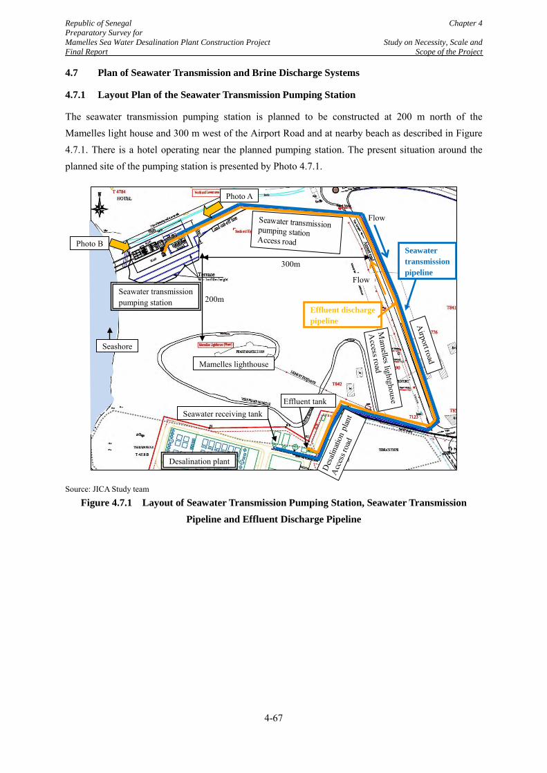
Republic of Senegal Chapter 4 Preparatory Survey for Mamelles Sea Water Desalination Plant Construction Project Study on Necessity, Scale and Final Report Scope of the Project
4.7 Plan of Seawater Transmission and Brine Discharge Systems
4.7.1 Layout Plan of the Seawater Transmission Pumping Station
The seawater transmission pumping station is planned to be constructed at 200 m north of the Mamelles light house and 300 m west of the Airport Road and at nearby beach as described in Figure 4.7.1. There is a hotel operating near the planned pumping station. The present situation around the planned site of the pumping station is presented by Photo 4.7.1.
Source: JICA Study team
Figure 4.7.1 Layout of Seawater Transmission Pumping Station, Seawater Transmission Pipeline and Effluent Discharge Pipeline
Effluent discharge pipeline
Desalination plant
Seawater transmission pumping station
Mamelles lighthouse
Seashore
Flow
Flow
Photo B
Photo A
Seawater transmission pipeline
Effluent tank
200m
Seawater receiving tank
300m
4-67
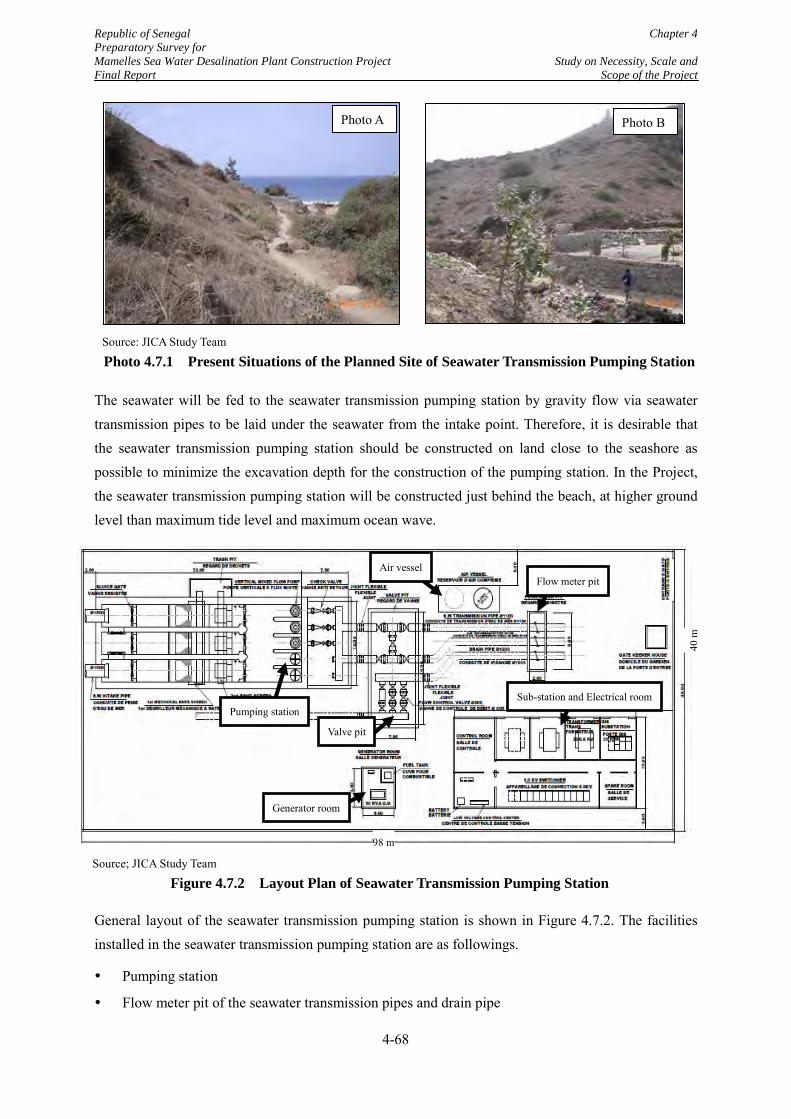
Republic of Senegal Chapter 4 Preparatory Survey for Mamelles Sea Water Desalination Plant Construction Project Study on Necessity, Scale and Final Report Scope of the Project
The seawater will be fed to the seawater transmission pumping station by gravity flow via seawater transmission pipes to be laid under the seawater from the intake point. Therefore, it is desirable that the seawater transmission pumping station should be constructed on land close to the seashore as possible to minimize the excavation depth for the construction of the pumping station. In the Project, the seawater transmission pumping station will be constructed just behind the beach, at higher ground level than maximum tide level and maximum ocean wave.
General layout of the seawater transmission pumping station is shown in Figure 4.7.2. The facilities installed in the seawater transmission pumping station are as followings.
Pumping station
Flow meter pit of the seawater transmission pipes and drain pipe
Source: JICA Study Team
Photo 4.7.1 Present Situations of the Planned Site of Seawater Transmission Pumping Station
Photo A Photo B
9
Source; JICA Study Team
Figure 4.7.2 Layout Plan of Seawater Transmission Pumping Station
98 m
40 m
Flow meter pit Air vessel
Pumping station
Valve pit
Generator room
Sub-station and Electrical room
4-68
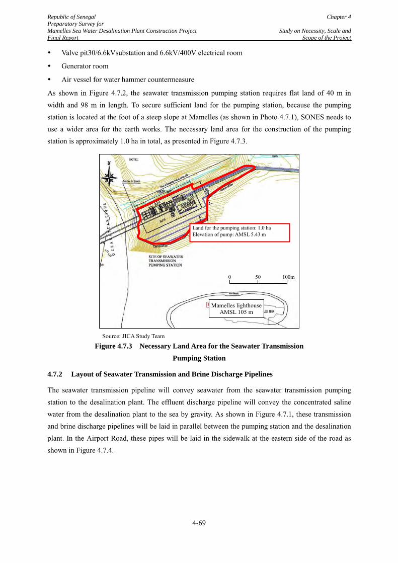
Republic of Senegal Chapter 4 Preparatory Survey for Mamelles Sea Water Desalination Plant Construction Project Study on Necessity, Scale and Final Report Scope of the Project
Valve pit30/6.6kVsubstation and 6.6kV/400V electrical room
Generator room
Air vessel for water hammer countermeasure
As shown in Figure 4.7.2, the seawater transmission pumping station requires flat land of 40 m in width and 98 m in length. To secure sufficient land for the pumping station, because the pumping station is located at the foot of a steep slope at Mamelles (as shown in Photo 4.7.1), SONES needs to use a wider area for the earth works. The necessary land area for the construction of the pumping station is approximately 1.0 ha in total, as presented in Figure 4.7.3.
Source: JICA Study Team
Figure 4.7.3 Necessary Land Area for the Seawater Transmission Pumping Station
4.7.2 Layout of Seawater Transmission and Brine Discharge Pipelines
The seawater transmission pipeline will convey seawater from the seawater transmission pumping station to the desalination plant. The effluent discharge pipeline will convey the concentrated saline water from the desalination plant to the sea by gravity. As shown in Figure 4.7.1, these transmission and brine discharge pipelines will be laid in parallel between the pumping station and the desalination plant. In the Airport Road, these pipes will be laid in the sidewalk at the eastern side of the road as shown in Figure 4.7.4.
Land for the pumping station: 1.0 ha Elevation of pump: AMSL 5.43 m
Mamelles lighthouse AMSL 105 m
0 50 100m
4-69
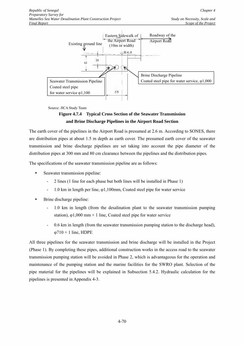
Republic of Senegal Chapter 4 Preparatory Survey for Mamelles Sea Water Desalination Plant Construction Project Study on Necessity, Scale and Final Report Scope of the Project
Source: JICA Study Team
Figure 4.7.4 Typical Cross Section of the Seawater Transmission and Brine Discharge Pipelines in the Airport Road Section
The earth cover of the pipelines in the Airport Road is presumed at 2.6 m. According to SONES, there are distribution pipes at about 1.5 m depth as earth cover. The presumed earth cover of the seawater transmission and brine discharge pipelines are set taking into account the pipe diameter of the distribution pipes at 300 mm and 80 cm clearance between the pipelines and the distribution pipes.
The specifications of the seawater transmission pipeline are as follows:
Seawater transmission pipeline:
- 2 lines (1 line for each phase but both lines will be installed in Phase 1)
- 1.0 km in length per line, φ1,100mm, Coated steel pipe for water service
Brine discharge pipeline:
- 1.0 km in length (from the desalination plant to the seawater transmission pumping station), φ1,000 mm × 1 line, Coated steel pipe for water service
- 0.6 km in length (from the seawater transmission pumping station to the discharge head), φ710 × 1 line, HDPE
All three pipelines for the seawater transmission and brine discharge will be installed in the Project (Phase 1). By completing these pipes, additional construction works in the access road to the seawater transmission pumping station will be avoided in Phase 2, which is advantageous for the operation and maintenance of the pumping station and the marine facilities for the SWRO plant. Selection of the pipe material for the pipelines will be explained in Subsection 5.4.2. Hydraulic calculation for the pipelines is presented in Appendix 4-3.
Brine Discharge Pipeline Coated steel pipe for water service, φ1,000
Roadway of the Airport Road
Eastern Sidewalk of the Airport Road (10m in width) Existing ground line
Seawater Transmission Pipeline Coated steel pipe for water service φ1,100
4-70
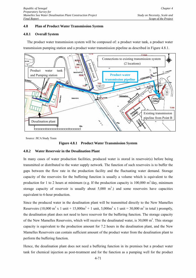
Republic of Senegal Chapter 4 Preparatory Survey for Mamelles Sea Water Desalination Plant Construction Project Study on Necessity, Scale and Final Report Scope of the Project
4.8 Plan of Product Water Transmission System
4.8.1 Overall System
The product water transmission system will be composed of: a product water tank, a product water transmission pumping station and a product water transmission pipeline as described in Figure 4.8.1.
Source: JICA Study Team
Figure 4.8.1 Product Water Transmission System
4.8.2 Water Reservoir in the Desalination Plant
In many cases of water production facilities, produced water is stored in reservoir(s) before being transmitted or distributed to the water supply network. The function of such reservoirs is to buffer the gaps between the flow rate in the production facility and the fluctuating water demand. Storage capacity of the reservoirs for the buffering function is usually a volume which is equivalent to the production for 1 to 2 hours at minimum (e.g. If the production capacity is 100,000 m3/day, minimum storage capacity of reservoir is usually about 5,000 m3.) and some reservoirs have capacities equivalent to 6-hour production.
Since the produced water in the desalination plant will be transmitted directly to the New Mamelles Reservoirs (10,000 m3 x 1 unit + 15,000m3 + 1 unit, 5,000m3 x 1 unit = 30,000 m3 in total ) promptly, the desalination plant does not need to have reservoir for the buffering function. The storage capacity of the New Mamelles Reservoirs, which will receive the desalinated water, is 30,000 m3. This storage capacity is equivalent to the production amount for 7.2 hours in the desalination plant, and the New Mamelles Reservoirs can contain sufficient amount of the product water from the desalination plant to perform the buffering function.
Hence, the desalination plant does not need a buffering function in its premises but a product water tank for chemical injection as post-treatment and for the function as a pumping well for the product
Desalination plant
Product water tank and Pumping station Product water
transmission pipeline
Connections to existing transmission system (2 locations)
Existing transmission pipeline from Point B
4-71
Republic of Senegal Chapter 4 Preparatory Survey for Mamelles Sea Water Desalination Plant Construction Project Study on Necessity, Scale and Final Report Scope of the Project
water pumping station is planned. The chemicals to be injected at the tank are calcium hydroxide and chloride. Calcium hydroxide will be for supplementing the minerals for the desalinated water and for pH adjustment. Storage capacity of the product water tank is to be determined to secure sufficient contact time with the chemicals. A tank of 2,000 m3 divided into two units is proposed, assuming 30 minutes of the contact time.
4.8.3 Product Water Transmission Pumping Station
The product water will be stored in the product water tank. From the tank, the product water will be transmitted to New Mamelles Reservoirs by the product water transmission pumps. The flow capacity of the product water at each phase will be as below, which was determined by nominal capacity of the desalination plant as explained in Section 5.1:
Flow rate at Phase 1: 53,191 m3/day (See Subsection 5.1.1 for the calculation of the flow rate.)
Flow rate at Phase 2: 53.191 m3/day additionally
The facilities to be installed in the pumping station are as follows:
Transmission pumps
400 V Motor starting panels
Suction and discharge pipes
Facility for water hammer countermeasure
4.8.4 Product Water Transmission Pipelines
As shown in Figure 4.8.1, the product water transmission pipelines will convey the product water from the desalination plant. The pipelines will be connected to the existing transmission system which currently conveys water from Point B to the Mamelles Reservoirs. The connection to the existing transmission system will enable the product water to be stored in the existing "New" Mamelles Reservoirs (5,000, 10,000 and 15,000 m3). To mitigate the risk of complete shutdown of the transmission system, the product water transmission system will have an independent line for each phase. The two pipelines will be constructed in the respective phases. Length of each line is assumed at 0.6 km, and the diameter is 800 mm. Pipe material is ductile cast iron. Hydraulic calculation for the product water transmission pipeline is presented in Appendix 4-3.
4-72
Republic of Senegal Chapter 4 Preparatory Survey for Mamelles Sea Water Desalination Plant Construction Project Study on Necessity, Scale and Final Report Scope of the Project
4.9 Study on Accessory Facilities of the Desalination Plant
(1) Substation and power line from the external network
As explained in Subsection 4.4.3, the Mamelles desalination Plant will receive the power supply from the existing 90kV line. The capacity of electric power required by the seawater desalination plant including seawater transmission pumps was calculated as 29 MW based on the ultimate capacity of 100,000 m3/day. Capacity of the substation for the desalination plant will be as below:
Phase 1 : 15 MW
Phase 2 : 30 MW
(2) Emergency power generator
In the request letter for financial assistance for the Mamelles Seawater Desalination Plant Construction Project from the Government of Senegal to the Government of Japan, issued in July 2013, a power generator to cover all treatment units in the plant was included in the project. This plan came out from the concern by SONES that a reliable power source might not be available for the plant.
As explained in Subsection 4.4.3, however, the JICA Study Team believes that the plant will be able to receive sufficient and stable power from SENELEC. In addition, a power generator to cover the all loads to operate the desalination plant will cost approximately F.CFA12 billion or JPY 2.4 billion assuming the necessary capacity in the 1st phase (15 MW).
Considering the extremely expensive costs for a generator and the expected reliability of the power source, it is concluded that the emergency power generator will be planned so that it will cover the equipment for security purposes such as follows:
Lighting for emergencies
Supervisory equipment and instrument
Ventilation and air conditioning apparatus
In case of a power cut, water production function of the desalination plant will be suspended. However, the New Mamelles Reservoirs, which have a total storage capacity of 30,000 m3/day, can continue the water supply for several hours to satisfy the water demand in its distribution area. The present water consumption in the distribution area of the New Mamelles Reservoirs is 70,000 m3/day which is the actual flow from Point B Pumping Station to the reservoirs. From the storage capacity and the water demand in the distribution area, the reservoirs could continue the water supply for more than five hours, if half amount of the storage capacity of water is stored when the power supply is cut. This is also one of the reasons that the extremely high investment in the generator to continue the water production will not be necessary.
4-73
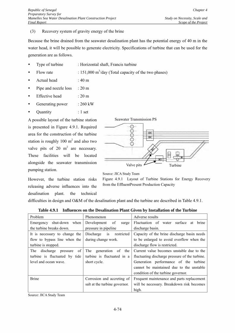
Republic of Senegal Chapter 4 Preparatory Survey for Mamelles Sea Water Desalination Plant Construction Project Study on Necessity, Scale and Final Report Scope of the Project
(3) Recovery system of gravity energy of the brine
Because the brine drained from the seawater desalination plant has the potential energy of 40 m in the water head, it will be possible to generate electricity. Specifications of turbine that can be used for the generation are as follows.
Type of turbine : Horizontal shaft, Francis turbine
Flow rate : 151,000 m3/day (Total capacity of the two phases)
Actual head : 40 m
Pipe and nozzle loss : 20 m
Effective head : 20 m
Generating power : 260 kW
Quantity : 1 set
A possible layout of the turbine station is presented in Figure 4.9.1. Required area for the construction of the turbine station is roughly 100 m2 and also two valve pits of 20 m2 are necessary. These facilities will be located alongside the seawater transmission pumping station.
However, the turbine station risks releasing adverse influences into the desalination plant. the technical difficulties in design and O&M of the desalination plant and the turbine are described in Table 4.9.1.
Table 4.9.1 Influences on the Desalination Plant Given by Installation of the Turbine Problem Phenomenon Adverse results Emergency shut-down when the turbine breaks down.
Development of surge pressure in pipeline
Fluctuation of water surface at brine discharge basin.
It is necessary to change the flow to bypass line when the turbine is stopped.
Discharge is restricted during change work.
Capacity of the brine discharge basin needs to be enlarged to avoid overflow when the discharge flow is restricted.
The discharge pressure of turbine is fluctuated by tide level and ocean wave.
The generation of the turbine is fluctuated in a short cycle.
Current value becomes unstable due to the fluctuating discharge pressure of the turbine. Generation performance of the turbine cannot be maintained due to the unstable condition of the turbine governor.
Brine Corrosion and accreting of salt at the turbine governor.
Frequent maintenance and parts replacement will be necessary. Breakdown risk becomes high.
Source: JICA Study Team
Source: JICA Study Team Figure 4.9.1 Layout of Turbine Stations for Energy Recovery from the EffluentPresent Production Capacity
Valve pits Turbine
Seawater Transmission PS
4-74
Republic of Senegal Chapter 4 Preparatory Survey for Mamelles Sea Water Desalination Plant Construction Project Study on Necessity, Scale and Final Report Scope of the Project
Although the generating power of the turbine (260 kW) is equivalent to only 1% of the loading capacity of the entire plant, installation of the turbine includes several technical difficulties as shown in Table 4.9.1. In addition, the land for the seawater transmission pumping station is so limited that the turbine installation will need additional cost for land preparation work. Therefore, it is concluded that the construction of the turbine plant is not feasible.
4-75
Republic of Senegal Chapter 4 Preparatory Survey for Mamelles Sea Water Desalination Plant Construction Project Study on Necessity, Scale and Final Report Scope of the Project
4.10 Study on the Necessity of Improvement of Distribution Network
In order to maximize the benefit of the construction project of the Mamelles SWRO Plant, the JICA Study Team proposes the renewal of distribution pipes for water loss reduction, water pressure improvement and 24-hour water supply services in the distribution area of the desalination plant.
(1) Present distribution network of the Mamelles SWRO Plant
The product water of the desalination plant will be distributed through the New Mamelles Reservoirs. The present distribution network of the New Mamelles Reservoirs is not fixed because the network from the reservoirs is not completely independent from the entire network. However, SONES and SDE roughly control the distribution area by operation of key valves in the main distribution pipes. From the usual operational mode of such valves, the present distribution area of the New Mamelles Reservoir has been estimated approximately, as illustrated in Figure 4.10.1.
(2) Future distribution area of the Mamelles SWRO Plant
After the construction of the Mamelles SWRO Plant, SONES has a plan to expand the distribution area of the New Mamelles Reservoirs, as also illustrated in Figure 4.10.1. Currently, the planned expansion area receives water from the ALG 2, the transmission line from the KMS2 WTP. However, in order to deliver sufficient water from KMS2 to Point B PS, SDE is forced to limit the flow to the planned expansion area by controlling a valve in a branch from ALG2 to the area. SONES and SDE plans to switch water sources of the area from KMS2 to the Mamelles SWRO Plant by closing the valve in the branch and in turn opening the valve in the main distribution pipe of DN400 to Front de Terre.
4-76
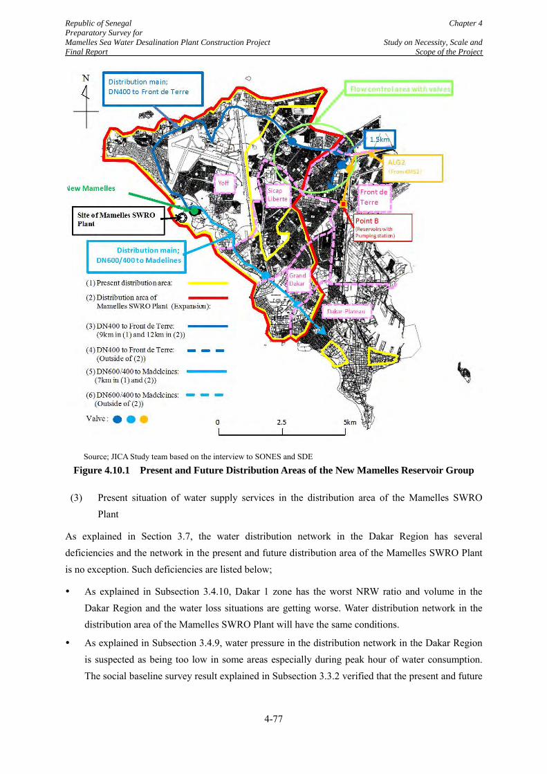
Republic of Senegal Chapter 4 Preparatory Survey for Mamelles Sea Water Desalination Plant Construction Project Study on Necessity, Scale and Final Report Scope of the Project
Source; JICA Study team based on the interview to SONES and SDE
Figure 4.10.1 Present and Future Distribution Areas of the New Mamelles Reservoir Group
(3) Present situation of water supply services in the distribution area of the Mamelles SWRO Plant
As explained in Section 3.7, the water distribution network in the Dakar Region has several deficiencies and the network in the present and future distribution area of the Mamelles SWRO Plant is no exception. Such deficiencies are listed below;
As explained in Subsection 3.4.10, Dakar 1 zone has the worst NRW ratio and volume in the Dakar Region and the water loss situations are getting worse. Water distribution network in the distribution area of the Mamelles SWRO Plant will have the same conditions.
As explained in Subsection 3.4.9, water pressure in the distribution network in the Dakar Region is suspected as being too low in some areas especially during peak hour of water consumption. The social baseline survey result explained in Subsection 3.3.2 verified that the present and future
4-77
Republic of Senegal Chapter 4 Preparatory Survey for Mamelles Sea Water Desalination Plant Construction Project Study on Necessity, Scale and Final Report Scope of the Project
distribution areas of the Mamelles SWRO Plant, which are Yoff, Grand Dakar, and Sicap Liberté sectors and a part of Dakar Plateau sector, have the same problem.
According to the social baseline survey results, the sector of Front de Terre, which is not in the distribution area of the Mamelles SWRO Plant, has the worst service level in the Dakar 1 Zone. The low service level will be derived from direct water receiving from ALG 2. If the water distribution area from reservoirs of Mamelles is expanded, necessary water to be diverted from ALG 2 will be reduced. It will improve the service level in the sector of Front de Terre.
(4) Necessity of the renewal of deteriorating distribution pipes for water loss reduction
As described in Subsection 3.4.10, the situations of water loss or NRW in the Dakar 1 Zone are the worst compared to the other zones in the region. All water loss indicators such as NRW ratio, NRW volume and LLI describe the worst situations in the Dakar 1 Zone and reveal that the situations are becoming worse year by year. Daily water loss in Dakar 1 zone in 2014 was 42,000 m3. This amount is more than the production capacity of Ngnith WTP (40,000 m3/day) and is more than the total storage capacity of the Mamelles Reservoirs. If the desalination plant is constructed leaving the present situations, much of the water produced in the plant will be lost before being delivered to the water users. It will deteriorate the project's benefit in such viewpoints as cost-effectiveness and satisfaction of water demand.
According to the performance contract between SONES and SDE, 85% of revenue water ratio or 15% of NRW ratio is given as an index value of water supply services. In the Dakar 1 Zone, the actual NRW ratio in 2010 was 20% but it increase to 26.9% by 2014. The JICA Study Team views a target of 15% may be too aggressive and proposes that 20% of NRW ratio will be the minimum target of the water loss reduction to be achieved initially.
In the Dakar Region, all service connections have water meters. Moreover, it is reported that the region is not an area where many people commit water theft. In these situations, water leaks from old distribution networks and service connections are suspected to be the major cause of the water losses. The JICA Study Team proposes the renewal of all distribution pipes of 40 years or more and service connections in the distribution pipes to be renewed.
More information on the pipe replacement for water loss reduction will be given in Subsection 5.10.
(5) Necessity of the replacement of distribution pipes of small diameter for water pressure improvement.
According to SONES, the minimum water pressure as target is 0.1 MPa at the end of service connection but it is not satisfied in wide areas in the Dakar Region. Insufficient water pressure is one of the deficiencies in the water supply services in the region.. In the social baseline survey conducted by the Study team, 63.3% of respondents answered water pressure was unstable or regularly low. Further, 31.7% of respondents answered they were not supplied with continuous water supply service. It is considered that, in many cases, suspension of the water supply services is derived from frequent
4-78
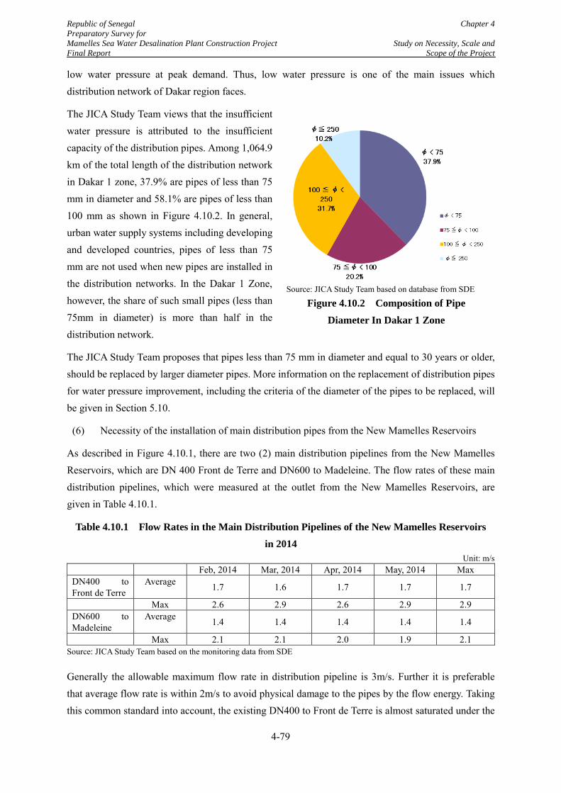
Republic of Senegal Chapter 4 Preparatory Survey for Mamelles Sea Water Desalination Plant Construction Project Study on Necessity, Scale and Final Report Scope of the Project
low water pressure at peak demand. Thus, low water pressure is one of the main issues which distribution network of Dakar region faces.
The JICA Study Team views that the insufficient water pressure is attributed to the insufficient capacity of the distribution pipes. Among 1,064.9 km of the total length of the distribution network in Dakar 1 zone, 37.9% are pipes of less than 75 mm in diameter and 58.1% are pipes of less than 100 mm as shown in Figure 4.10.2. In general, urban water supply systems including developing and developed countries, pipes of less than 75 mm are not used when new pipes are installed in the distribution networks. In the Dakar 1 Zone, however, the share of such small pipes (less than 75mm in diameter) is more than half in the distribution network.
The JICA Study Team proposes that pipes less than 75 mm in diameter and equal to 30 years or older, should be replaced by larger diameter pipes. More information on the replacement of distribution pipes for water pressure improvement, including the criteria of the diameter of the pipes to be replaced, will be given in Section 5.10.
(6) Necessity of the installation of main distribution pipes from the New Mamelles Reservoirs
As described in Figure 4.10.1, there are two (2) main distribution pipelines from the New Mamelles Reservoirs, which are DN 400 Front de Terre and DN600 to Madeleine. The flow rates of these main distribution pipelines, which were measured at the outlet from the New Mamelles Reservoirs, are given in Table 4.10.1.
Table 4.10.1 Flow Rates in the Main Distribution Pipelines of the New Mamelles Reservoirs in 2014
Unit: m/s Feb, 2014 Mar, 2014 Apr, 2014 May, 2014 Max DN400 to Front de Terre
Average 1.7 1.6 1.7 1.7 1.7
Max 2.6 2.9 2.6 2.9 2.9 DN600 to Madeleine
Average 1.4 1.4 1.4 1.4 1.4
Max 2.1 2.1 2.0 1.9 2.1 Source: JICA Study Team based on the monitoring data from SDE
Generally the allowable maximum flow rate in distribution pipeline is 3m/s. Further it is preferable that average flow rate is within 2m/s to avoid physical damage to the pipes by the flow energy. Taking this common standard into account, the existing DN400 to Front de Terre is almost saturated under the
Source: JICA Study Team based on database from SDE
Figure 4.10.2 Composition of Pipe Diameter In Dakar 1 Zone
4-79
Republic of Senegal Chapter 4 Preparatory Survey for Mamelles Sea Water Desalination Plant Construction Project Study on Necessity, Scale and Final Report Scope of the Project
current flow conditions, while the existing DN600 is not yet in the similar status. Since the distribution area of the New Mamelles Reservoris will be expanded as shown in Figure 4.101, obviously reinforcement of the existing DN400 is necessary. The Study proposes to install a new distribution main of DN700 in parallel with the existing DN400 as shown in Figure 4.10.1. Design of the new distribution main will be explained in Section 5.1.
(7) Proposed length of the distribution pipeline to be renewed and replaced
1) Target area of the improvement of the distribution network
Product water from the Mamelles SWRO Plant will be distributed to the existing distribution networks that are extended from the “New Mamelles Reservoirs” that are also existing. The main distribution lines from the reservoirs are DN400 to Fronte de Terre and DN600/400 to Madelines. These main lines are not independent from the distribution areas of the other reservoirs and pumping stations. Practically, the affection area of the New Mamelles Reservoirs is always changing according to the water pressure balance in the water distribution network.
In this situation, the JICA Study Team proposes that the improvement of the existing distribution network in the Project cover the entire Dakar 1 Zone. This plan will ensure the maximization of the benefit of the construction of the SWRO plant and the Project’s high contribution to improvement of the living conditions of the people in the Dakar Region.
2) Total pipe length to be replaced in the distribution area of the Mamelles SWRO Plant
Pipe length of 40 years or older, which meet the criteria of the pipes to be renewed for water loss reduction, is estimated at 412 km in the Dakar 1 Zone.
Furthermore, the JICA Study Team proposes that pipes less than 75 mm and of 30 years old or more should be replaced by larger diameter pipes to improve water pressure for better water supply services. Such pipes in the Dakar 1 Zone are 167 km from the inventory of SONES/SDE. . Deducting the overlapping length of the two pipe categories above, which are those smaller than 75 mm and 40 years old or more, proposed pipe length to be renewed or replaced for the improvement of the existing distribution network are 442 km. Table 4.10.3 shows length of the pipe construction works in the Project, which are for the replacement and reinforcement.
Table 4.10.2 Length of Improvement of Distribution Pipe Objectives For water loss reduction For water pressure
improvement Installation of the main
distribution pipe Target of the replacement or reinforcement
Distribution pipe of 40 years or older than 40 years (replacement)
Distribution pipe with diameter less than 75 mm and of 30 years or older than 30 years (replacement)
DN 700 to Font de Terre (reinforcement)
Length 412km 167 km 13.5 km 442 km*
*: Since distribution pipes to be replaced for water loss reduction (412 km) and for water pressure improvement (167 km) are overlapped, the simple total sum of them is not the total length of the replacement.
Source: JICA Study Team
4-80
Republic of Senegal Chapter 4 Preparatory Survey for Mamelles Sea Water Desalination Plant Construction Project Study on Necessity, Scale and Final Report Scope of the Project
(8) Installation of booster pumps and sectorization of the distribution network
SONES/SDE is conducting regular water pressure monitoring at some points in the distribution network. Some of the monitoring points are the fixed locations and the others are temporally ones. By the monitoring, SONES/SDE identify the areas with disrupted water supply services in the Dakar 1 Zone, most of which are caused by insufficient water pressure. By overlapping the locations of such areas and the contours, it is observed that the high elevation areas tend to be suffering from the disrupted water supply services due to the insufficient water pressure. To improve the water supply services in these high elevation areas, the Study proposes to install booster pumps in the Project. The plan will be explained in Section 5.10.
In addition to the booster pumps, the JICA Study Team proposes to carry out “sectorization” of the existing distribution network or setup of district metered areas (DMAs) in the Project. Being combined with the replacement work of the deteriorated and small-diameter distribution pipes, the sectorization will achieve good water loss and water pressure management. This plan will also be explained in Section 5.10.
4-81
Republic of Senegal Chapter 4 Preparatory Survey for Mamelles Sea Water Desalination Plant Construction Project Study on Necessity, Scale and Final Report Scope of the Project
4.11 Principal Feature of the Project
Based on the studies above, general scope of the Project is planned as shown in Table 4.11.1. Overall project layout, excluding the distribution network improvement, is shown in Figure 4.11.1.
Table 4.11.1 General Scope of the Mamelles Seawater Desalination Plant Construction Project Item Specification
I. Seawater desalination facilities
1. Seawater intake and brine discharge facilities
Seawater intake
Deep water intake Intake pipeline: D = 1,200 mm, L = 350 m x 2 lines, HDPE*1
Brine discharge
Deep water discharge Discharge pipeline (From the valve pit-to the discharge head): D = 710 mm, L = 500 m*2, HDPE*1
2. Seawater transmission pumping station
Vertical, Mixed flow pump Q = 44.83 m3/min (64,560 m3/day), H = 62 m, 3 units including 1 stand-by
3. Seawater transmission pipeline and brine discharge pipeline
Transmission pipeline
D = 1,100 mm, L = 1.01 km x 2 lines, Coated steel pipe for water service
Discharge pipeline (Seawater desalination plant – Valve pit)
D=1,000mm, L=0.96km, Coated steel pipe for water service
4. Seawater desalination plant Q = 53,191 m3/day, Recovery ratio: 45% Reverse osmosis (RO) process Including a substation (90 kV/30 kV, 13 MVA)
5. Product water transmission pumping station
Horizontal double suction pump Q = 18.47 m3/min (26,600 m3/day), H = 22 m, 3 units including 1 stand-by
6. Product water transmission pipeline
Ductile cast iron pipe, φ800 mm, 0.63 km Ductile cast iron pipe
7. Land development for the plant sites
4.96 ha (1.00 ha: Seawater transmission pumping station) (3.96 ha: desalination plant)
II Improvement of distribution network
- Installation of main distribution line (D700, L = 13.5 km) - Replacement of the existing distribution pipes (Distribution area of
Mamelles SWRO Plant: D75 – D700, L = 242.7 km) - Replacement of the existing distribution pipes (Dakar 1 zone
excluding distribution area of Mamelles SWRO Plant: D75 – D700, L = 198.6 km)
- Renewal of service connections, branched from the distribution pipes to be replaced, and the water meter (116,000 locations)
- Booster pumping station; 3 locations - Sectorization of distribution network
*1 HDPE: High density polyethylene pipe *2 Length based on the result of brine diffusion analysis mentioned in Chapter 5.
Source: JICA Study Team
4-82
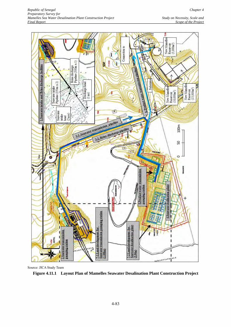
Republic of Senegal Chapter 4 Preparatory Survey for Mamelles Sea Water Desalination Plant Construction Project Study on Necessity, Scale and Final Report Scope of the Project
Source: JICA Study Team
Figure 4.11.1 Layout Plan of Mamelles Seawater Desalination Plant Construction Project
010
0m50
4-83
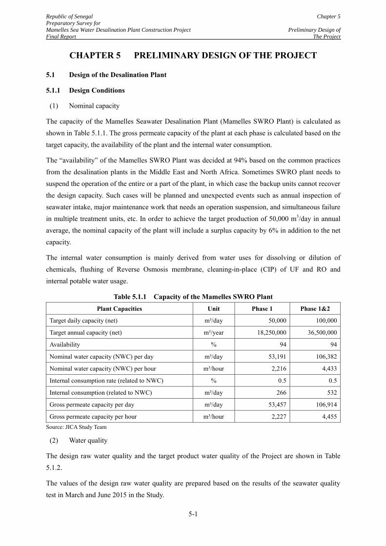
Republic of Senegal Chapter 5
Preparatory Survey for
Mamelles Sea Water Desalination Plant Construction Project Preliminary Design of
Final Report The Project
5-1
CHAPTER 5 PRELIMINARY DESIGN OF THE PROJECT
5.1 Design of the Desalination Plant
5.1.1 Design Conditions
(1) Nominal capacity
The capacity of the Mamelles Seawater Desalination Plant (Mamelles SWRO Plant) is calculated as shown in Table 5.1.1. The gross permeate capacity of the plant at each phase is calculated based on the target capacity, the availability of the plant and the internal water consumption.
The “availability” of the Mamelles SWRO Plant was decided at 94% based on the common practices from the desalination plants in the Middle East and North Africa. Sometimes SWRO plant needs to suspend the operation of the entire or a part of the plant, in which case the backup units cannot recover the design capacity. Such cases will be planned and unexpected events such as annual inspection of seawater intake, major maintenance work that needs an operation suspension, and simultaneous failure in multiple treatment units, etc. In order to achieve the target production of 50,000 m3/day in annual average, the nominal capacity of the plant will include a surplus capacity by 6% in addition to the net capacity.
The internal water consumption is mainly derived from water uses for dissolving or dilution of chemicals, flushing of Reverse Osmosis membrane, cleaning-in-place (CIP) of UF and RO and internal potable water usage.
Table 5.1.1 Capacity of the Mamelles SWRO Plant Plant Capacities Unit Phase 1 Phase 1&2
Target daily capacity (net) m³/day 50,000 100,000
Target annual capacity (net) m³/year 18,250,000 36,500,000
Availability % 94 94
Nominal water capacity (NWC) per day m³/day 53,191 106,382
Nominal water capacity (NWC) per hour m³/hour 2,216 4,433
Internal consumption rate (related to NWC) % 0.5 0.5
Internal consumption (related to NWC) m³/day 266 532
Gross permeate capacity per day m³/day 53,457 106,914
Gross permeate capacity per hour m³/hour 2,227 4,455 Source: JICA Study Team
(2) Water quality
The design raw water quality and the target product water quality of the Project are shown in Table 5.1.2.
The values of the design raw water quality are prepared based on the results of the seawater quality test in March and June 2015 in the Study.
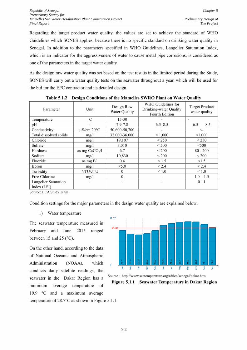
Republic of Senegal Chapter 5
Preparatory Survey for
Mamelles Sea Water Desalination Plant Construction Project Preliminary Design of
Final Report The Project
5-2
Regarding the target product water quality, the values are set to achieve the standard of WHO Guidelines which SONES applies, because there is no specific standard on drinking water quality in Senegal. In addition to the parameters specified in WHO Guidelines, Langelier Saturation Index, which is an indicator for the aggressiveness of water to cause metal pipe corrosions, is considered as one of the parameters in the target water quality.
As the design raw water quality was set based on the test results in the limited period during the Study, SONES will carry out a water quality tests on the seawater throughout a year, which will be used for the bid for the EPC contractor and its detailed design.
Table 5.1.2 Design Conditions of the Mamelles SWRO Plant on Water Quality
Parameter Unit Design Raw Water Quality
WHO Guidelines for Drinking-water Quality
Fourth Edition
Target Product water quality
Temperature °C 15-30 - - pH - 7.9-7.8 6.5–8.5 6.5 – 8.5 Conductivity S/cm 20C 50,600-50,700 - <- Total dissolved solids mg/l 32,000-36,000 < 1,000 <1,000 Chloride mg/l 19,107 < 250 < 250 Sulfate mg/l 3,010 < 500 <500 Hardness as mg CaCO3/l 6.7 < 200 80 - 200 Sodium mg/l 10,830 < 200 < 200 Fluoride as mg F/l 0.4 < 1.5 <1.5 Boron mg/l <5.0 < 2.4 < 2.4 Turbidity NTU/JTU 0 < 1.0 < 1.0 Free Chlorine mg/l 0 - 1.0 – 1.5 Langelier Saturation Index (LSI)
- - - 0 - 1
Source: JICA Study Team
Condition settings for the major parameters in the design water quality are explained below:
1) Water temperature
The seawater temperature measured in February and June 2015 ranged between 15 and 25 (°C).
On the other hand, according to the data of National Oceanic and Atmospheric Administration (NOAA), which conducts daily satellite readings, the seawater in the Dakar Region has a minimum average temperature of 19.9 °C and a maximum average temperature of 28.7°C as shown in Figure 5.1.1.
Source:http://www.seatemperature.org/africa/senegal/dakar.htm
Figure 5.1.1 Seawater Temperature in Dakar Region
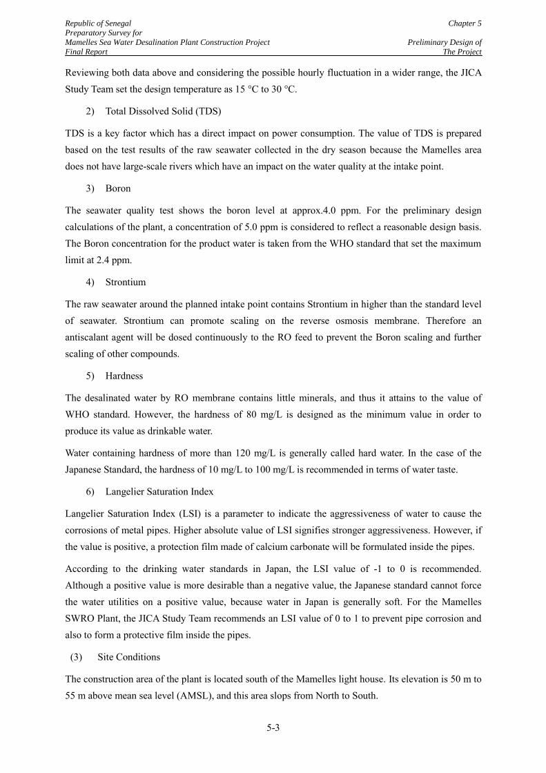
Republic of Senegal Chapter 5
Preparatory Survey for
Mamelles Sea Water Desalination Plant Construction Project Preliminary Design of
Final Report The Project
5-3
Reviewing both data above and considering the possible hourly fluctuation in a wider range, the JICA Study Team set the design temperature as 15 °C to 30 °C.
2) Total Dissolved Solid (TDS)
TDS is a key factor which has a direct impact on power consumption. The value of TDS is prepared based on the test results of the raw seawater collected in the dry season because the Mamelles area does not have large-scale rivers which have an impact on the water quality at the intake point.
3) Boron
The seawater quality test shows the boron level at approx.4.0 ppm. For the preliminary design calculations of the plant, a concentration of 5.0 ppm is considered to reflect a reasonable design basis. The Boron concentration for the product water is taken from the WHO standard that set the maximum limit at 2.4 ppm.
4) Strontium
The raw seawater around the planned intake point contains Strontium in higher than the standard level of seawater. Strontium can promote scaling on the reverse osmosis membrane. Therefore an antiscalant agent will be dosed continuously to the RO feed to prevent the Boron scaling and further scaling of other compounds.
5) Hardness
The desalinated water by RO membrane contains little minerals, and thus it attains to the value of WHO standard. However, the hardness of 80 mg/L is designed as the minimum value in order to produce its value as drinkable water.
Water containing hardness of more than 120 mg/L is generally called hard water. In the case of the Japanese Standard, the hardness of 10 mg/L to 100 mg/L is recommended in terms of water taste.
6) Langelier Saturation Index
Langelier Saturation Index (LSI) is a parameter to indicate the aggressiveness of water to cause the corrosions of metal pipes. Higher absolute value of LSI signifies stronger aggressiveness. However, if the value is positive, a protection film made of calcium carbonate will be formulated inside the pipes.
According to the drinking water standards in Japan, the LSI value of -1 to 0 is recommended. Although a positive value is more desirable than a negative value, the Japanese standard cannot force the water utilities on a positive value, because water in Japan is generally soft. For the Mamelles SWRO Plant, the JICA Study Team recommends an LSI value of 0 to 1 to prevent pipe corrosion and also to form a protective film inside the pipes.
(3) Site Conditions
The construction area of the plant is located south of the Mamelles light house. Its elevation is 50 m to 55 m above mean sea level (AMSL), and this area slops from North to South.
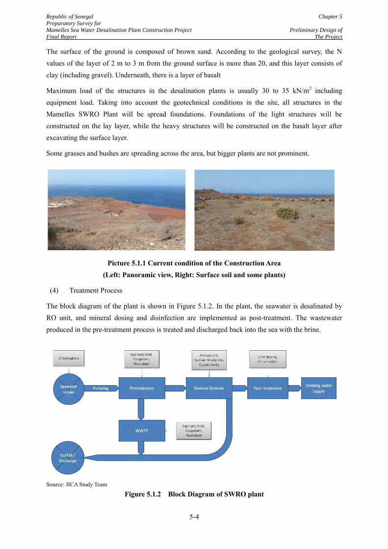
Republic of Senegal Chapter 5
Preparatory Survey for
Mamelles Sea Water Desalination Plant Construction Project Preliminary Design of
Final Report The Project
5-4
The surface of the ground is composed of brown sand. According to the geological survey, the N values of the layer of 2 m to 3 m from the ground surface is more than 20, and this layer consists of clay (including gravel). Underneath, there is a layer of basalt
Maximum load of the structures in the desalination plants is usually 30 to 35 kN/m2 including equipment load. Taking into account the geotechnical conditions in the site, all structures in the Mamelles SWRO Plant will be spread foundations. Foundations of the light structures will be constructed on the lay layer, while the heavy structures will be constructed on the basalt layer after excavating the surface layer.
Some grasses and bushes are spreading across the area, but bigger plants are not prominent.
Picture 5.1.1 Current condition of the Construction Area (Left: Panoramic view, Right: Surface soil and some plants)
(4) Treatment Process
The block diagram of the plant is shown in Figure 5.1.2. In the plant, the seawater is desalinated by RO unit, and mineral dosing and disinfection are implemented as post-treatment. The wastewater produced in the pre-treatment process is treated and discharged back into the sea with the brine.
Source: JICA Study Team
Figure 5.1.2 Block Diagram of SWRO plant
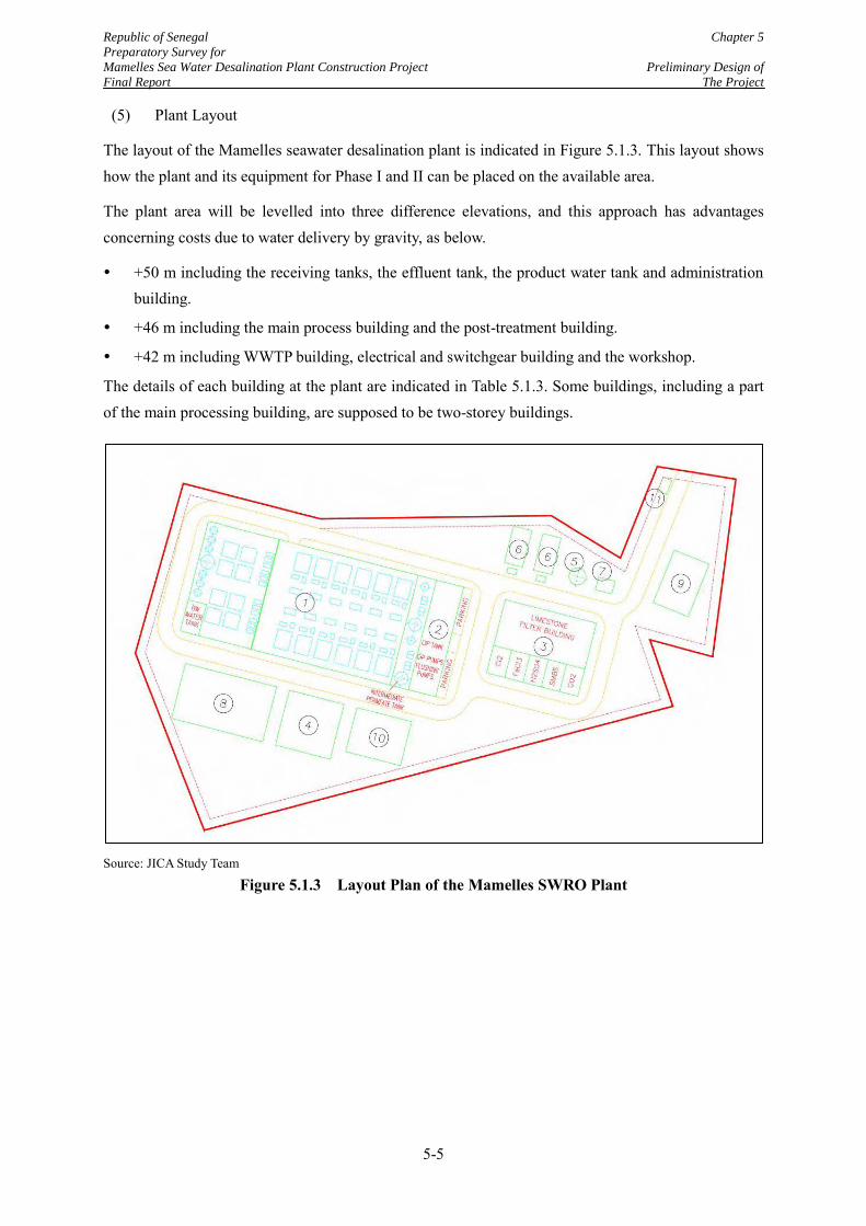
Republic of Senegal Chapter 5
Preparatory Survey for
Mamelles Sea Water Desalination Plant Construction Project Preliminary Design of
Final Report The Project
5-5
(5) Plant Layout
The layout of the Mamelles seawater desalination plant is indicated in Figure 5.1.3. This layout shows how the plant and its equipment for Phase I and II can be placed on the available area.
The plant area will be levelled into three difference elevations, and this approach has advantages concerning costs due to water delivery by gravity, as below.
+50 m including the receiving tanks, the effluent tank, the product water tank and administration building.
+46 m including the main process building and the post-treatment building.
+42 m including WWTP building, electrical and switchgear building and the workshop.
The details of each building at the plant are indicated in Table 5.1.3. Some buildings, including a part of the main processing building, are supposed to be two-storey buildings.
Source: JICA Study Team
Figure 5.1.3 Layout Plan of the Mamelles SWRO Plant
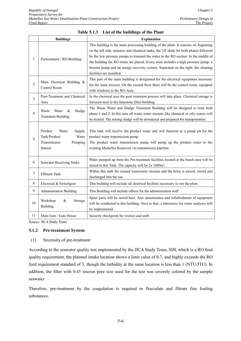
Republic of Senegal Chapter 5
Preparatory Survey for
Mamelles Sea Water Desalination Plant Construction Project Preliminary Design of
Final Report The Project
5-6
Table 5.1.3 List of the buildings of the Plant Buildings Explanation
1 Pretreatment / RO-Building
This building is the main processing building of the plant. It consists of, beginning on the left side, strainers and chemical tanks, the UF-skids for both phases followed by the low pressure pumps to transmit the water to the RO section. In the middle of the building the RO trains are placed. Every train includes a high pressure pump, a booster pump and an energy recovery system. Separated on the right, the cleaning facilities are installed.
2 Main Electrical Building & Control Room
This part of the main building is designated for the electrical equipment necessary for the main process. On the second floor there will be the control room, equipped with windows to the RO-Area.
3 Post-Treatment and Chemical Area
In the chemical area the post treatment process will take place. Chemical storage is foreseen next to the limestone filter-building.
4 Waste Water & Sludge Treatment Building
The Waste Water and Sludge Treatment Building will be designed to treat both phase 1 and 2. In this area all waste water streams like chemical or oily waters will be treated. The arising sludge will be dewatered and prepared for transportation.
5
Product Water Supply Tank/Product Water Transmission Pumping Station
This tank will receive the product water and will function as a pump pit for the product water transmission pump. The product water transmission pump will pump up the product water to the existing Mamelles Reservoir via transmission pipeline.
6 Seawater Receiving Tanks Water pumped up from the Pre-treatment facilities located at the beach area will be stored in this Tank. The capacity will be 2x 1800m³.
7 Effluent Tank Within this tank the treated wastewater streams and the brine is mixed, stored and discharged into the sea.
8 Electrical & Switchgear This building will include all electrical facilities necessary to run the plant.
9 Administration Building This Building will include offices for the administration staff
10 Workshop & Storage Building
Spare parts will be stored here. Also maintenance and refurbishment of equipment will be conducted in this building. Next to that, a laboratory for water analyses will be implemented.
11 Main Gate / Gate House Security checkpoint for visitors and staff.
Source: JICA Study Team
5.1.2 Pre-treatment System
(1) Necessity of pre-treatment
According to the seawater quality test implemented by the JICA Study Team, SDI, which is a RO feed quality requirement, the planned intake location shows a limit value of 6.7, and highly exceeds the RO feed requirement standard of 3, though the turbidity at the same location is less than 1 (NTU/JTU). In addition, the filter with 0.45 micron pore size used for the test was severely colored by the sample seawater
Therefore, pre-treatment by the coagulation is required to flocculate and filtrate fine fouling substances.
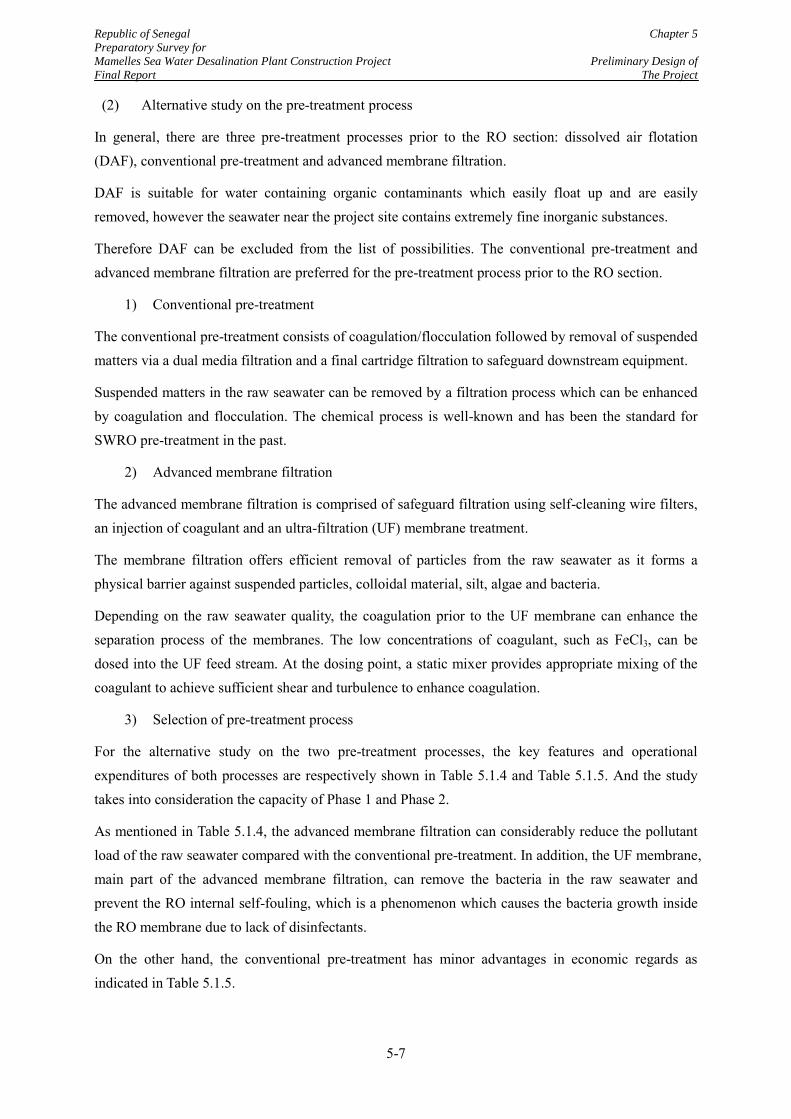
Republic of Senegal Chapter 5
Preparatory Survey for
Mamelles Sea Water Desalination Plant Construction Project Preliminary Design of
Final Report The Project
5-7
(2) Alternative study on the pre-treatment process
In general, there are three pre-treatment processes prior to the RO section: dissolved air flotation (DAF), conventional pre-treatment and advanced membrane filtration.
DAF is suitable for water containing organic contaminants which easily float up and are easily removed, however the seawater near the project site contains extremely fine inorganic substances.
Therefore DAF can be excluded from the list of possibilities. The conventional pre-treatment and advanced membrane filtration are preferred for the pre-treatment process prior to the RO section.
1) Conventional pre-treatment
The conventional pre-treatment consists of coagulation/flocculation followed by removal of suspended matters via a dual media filtration and a final cartridge filtration to safeguard downstream equipment.
Suspended matters in the raw seawater can be removed by a filtration process which can be enhanced by coagulation and flocculation. The chemical process is well-known and has been the standard for SWRO pre-treatment in the past.
2) Advanced membrane filtration
The advanced membrane filtration is comprised of safeguard filtration using self-cleaning wire filters, an injection of coagulant and an ultra-filtration (UF) membrane treatment.
The membrane filtration offers efficient removal of particles from the raw seawater as it forms a physical barrier against suspended particles, colloidal material, silt, algae and bacteria.
Depending on the raw seawater quality, the coagulation prior to the UF membrane can enhance the separation process of the membranes. The low concentrations of coagulant, such as FeCl3, can be dosed into the UF feed stream. At the dosing point, a static mixer provides appropriate mixing of the coagulant to achieve sufficient shear and turbulence to enhance coagulation.
3) Selection of pre-treatment process
For the alternative study on the two pre-treatment processes, the key features and operational expenditures of both processes are respectively shown in Table 5.1.4 and Table 5.1.5. And the study takes into consideration the capacity of Phase 1 and Phase 2.
As mentioned in Table 5.1.4, the advanced membrane filtration can considerably reduce the pollutant load of the raw seawater compared with the conventional pre-treatment. In addition, the UF membrane, main part of the advanced membrane filtration, can remove the bacteria in the raw seawater and prevent the RO internal self-fouling, which is a phenomenon which causes the bacteria growth inside the RO membrane due to lack of disinfectants.
On the other hand, the conventional pre-treatment has minor advantages in economic regards as indicated in Table 5.1.5.
Republic of Senegal Chapter 5
Preparatory Survey for
Mamelles Sea Water Desalination Plant Construction Project Preliminary Design of
Final Report The Project
5-8
However, the advanced membrane filtration was selected because of the following advantages.
Less frequent replacement of RO membrane
Lesser amount of sludge waste
Lower susceptibility to inferior quality sea water
Smaller floor print
The pre-treatment process should be finally selected in consideration of the whole treatment processes including the design of the RO section based on the seawater quality data throughout a year. Therefore, the suitable pre-treatment process can be proposed again in the bidding.
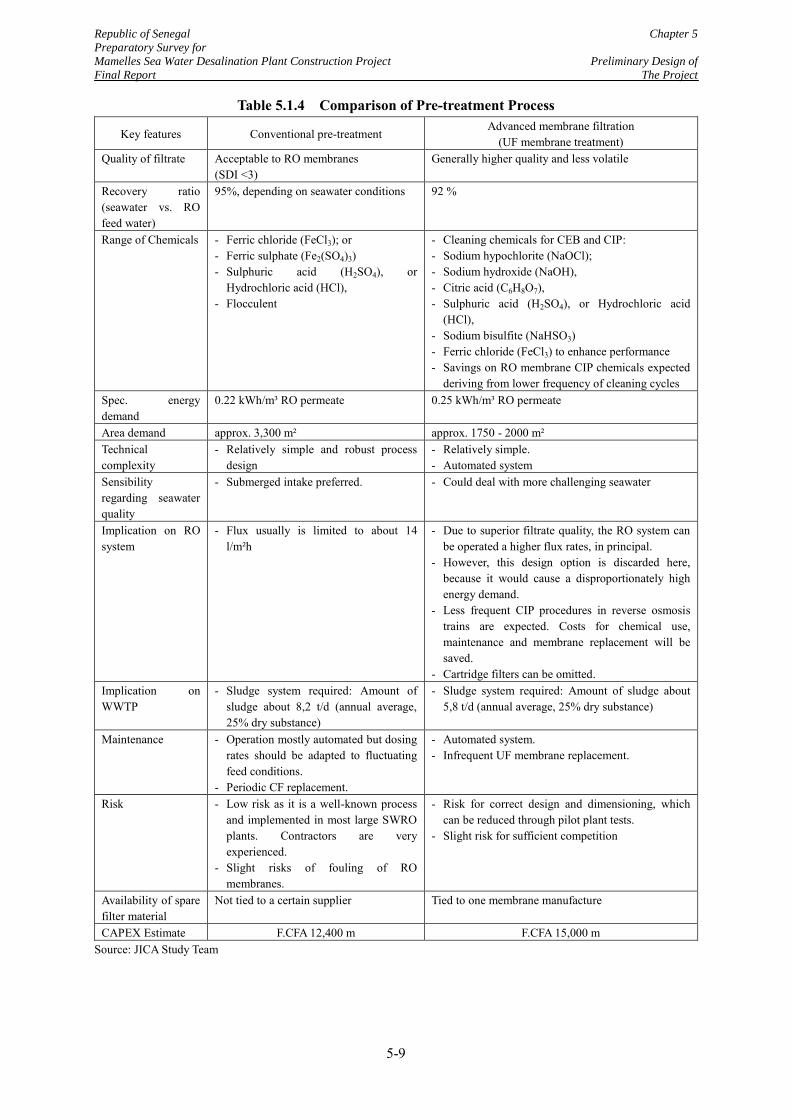
Republic of Senegal Chapter 5
Preparatory Survey for
Mamelles Sea Water Desalination Plant Construction Project Preliminary Design of
Final Report The Project
5-9
Table 5.1.4 Comparison of Pre-treatment Process
Key features Conventional pre-treatment Advanced membrane filtration
(UF membrane treatment) Quality of filtrate Acceptable to RO membranes
(SDI <3) Generally higher quality and less volatile
Recovery ratio (seawater vs. RO feed water)
95%, depending on seawater conditions 92 %
Range of Chemicals - Ferric chloride (FeCl3); or - Ferric sulphate (Fe2(SO4)3) - Sulphuric acid (H2SO4), or
Hydrochloric acid (HCl), - Flocculent
- Cleaning chemicals for CEB and CIP: - Sodium hypochlorite (NaOCl); - Sodium hydroxide (NaOH), - Citric acid (C6H8O7), - Sulphuric acid (H2SO4), or Hydrochloric acid
(HCl), - Sodium bisulfite (NaHSO3) - Ferric chloride (FeCl3) to enhance performance - Savings on RO membrane CIP chemicals expected
deriving from lower frequency of cleaning cycles Spec. energy demand
0.22 kWh/m³ RO permeate 0.25 kWh/m³ RO permeate
Area demand approx. 3,300 m² approx. 1750 - 2000 m² Technical complexity
- Relatively simple and robust process design
- Relatively simple. - Automated system
Sensibility regarding seawater quality
- Submerged intake preferred. - Could deal with more challenging seawater
Implication on RO system
- Flux usually is limited to about 14 l/m²h
- Due to superior filtrate quality, the RO system can be operated a higher flux rates, in principal.
- However, this design option is discarded here, because it would cause a disproportionately high energy demand.
- Less frequent CIP procedures in reverse osmosis trains are expected. Costs for chemical use, maintenance and membrane replacement will be saved.
- Cartridge filters can be omitted. Implication on WWTP
- Sludge system required: Amount of sludge about 8,2 t/d (annual average, 25% dry substance)
- Sludge system required: Amount of sludge about 5,8 t/d (annual average, 25% dry substance)
Maintenance - Operation mostly automated but dosing rates should be adapted to fluctuating feed conditions.
- Periodic CF replacement.
- Automated system. - Infrequent UF membrane replacement.
Risk - Low risk as it is a well-known process and implemented in most large SWRO plants. Contractors are very experienced.
- Slight risks of fouling of RO membranes.
- Risk for correct design and dimensioning, which can be reduced through pilot plant tests.
- Slight risk for sufficient competition
Availability of spare filter material
Not tied to a certain supplier Tied to one membrane manufacture
CAPEX Estimate F.CFA 12,400 m F.CFA 15,000 m Source: JICA Study Team
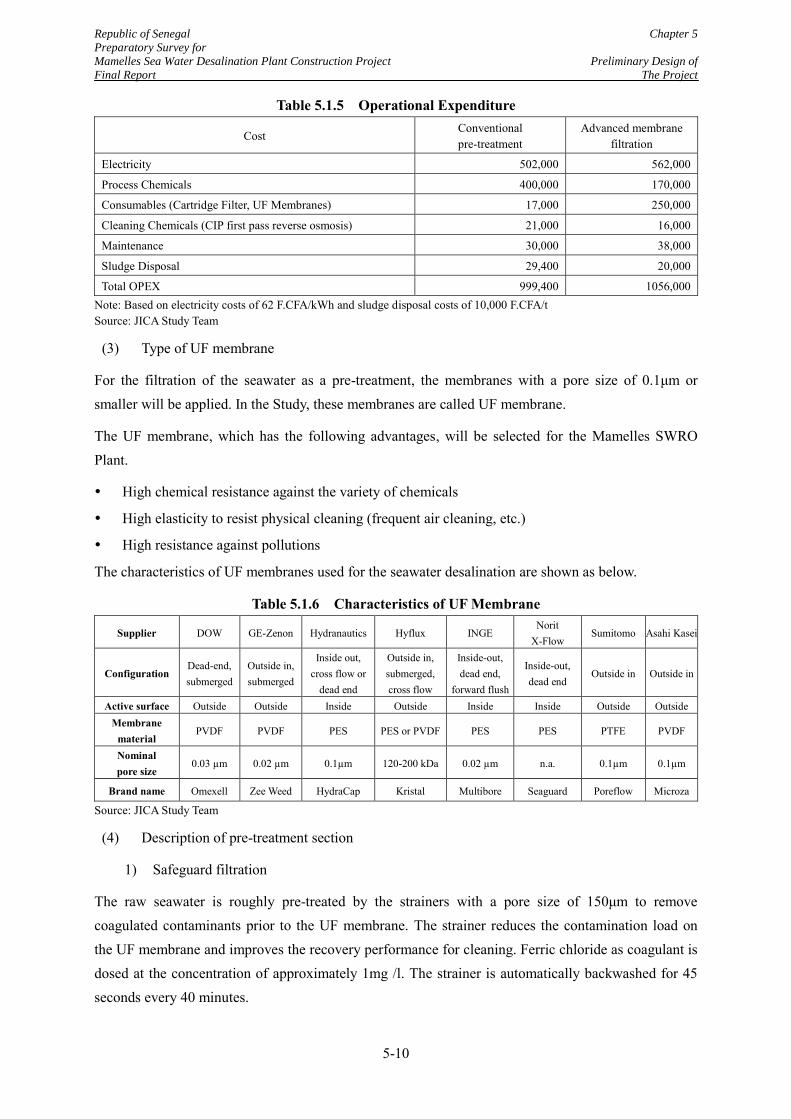
Republic of Senegal Chapter 5
Preparatory Survey for
Mamelles Sea Water Desalination Plant Construction Project Preliminary Design of
Final Report The Project
5-10
Table 5.1.5 Operational Expenditure
Cost Conventional pre-treatment
Advanced membrane filtration
Electricity 502,000 562,000
Process Chemicals 400,000 170,000
Consumables (Cartridge Filter, UF Membranes) 17,000 250,000
Cleaning Chemicals (CIP first pass reverse osmosis) 21,000 16,000
Maintenance 30,000 38,000
Sludge Disposal 29,400 20,000
Total OPEX 999,400 1056,000 Note: Based on electricity costs of 62 F.CFA/kWh and sludge disposal costs of 10,000 F.CFA/t Source: JICA Study Team
(3) Type of UF membrane
For the filtration of the seawater as a pre-treatment, the membranes with a pore size of 0.1μm or smaller will be applied. In the Study, these membranes are called UF membrane.
The UF membrane, which has the following advantages, will be selected for the Mamelles SWRO Plant.
High chemical resistance against the variety of chemicals
High elasticity to resist physical cleaning (frequent air cleaning, etc.)
High resistance against pollutions
The characteristics of UF membranes used for the seawater desalination are shown as below.
Table 5.1.6 Characteristics of UF Membrane
Supplier DOW GE-Zenon Hydranautics Hyflux INGE Norit
X-Flow Sumitomo Asahi Kasei
Configuration Dead-end, submerged
Outside in, submerged
Inside out, cross flow or
dead end
Outside in, submerged, cross flow
Inside-out, dead end,
forward flush
Inside-out, dead end
Outside in Outside in
Active surface Outside Outside Inside Outside Inside Inside Outside Outside Membrane
material PVDF PVDF PES PES or PVDF PES PES PTFE PVDF
Nominal pore size
0.03 µm 0.02 µm 0.1µm 120-200 kDa 0.02 µm n.a. 0.1µm 0.1µm
Brand name Omexell Zee Weed HydraCap Kristal Multibore Seaguard Poreflow Microza
Source: JICA Study Team
(4) Description of pre-treatment section
1) Safeguard filtration
The raw seawater is roughly pre-treated by the strainers with a pore size of 150μm to remove coagulated contaminants prior to the UF membrane. The strainer reduces the contamination load on the UF membrane and improves the recovery performance for cleaning. Ferric chloride as coagulant is dosed at the concentration of approximately 1mg /l. The strainer is automatically backwashed for 45 seconds every 40 minutes.
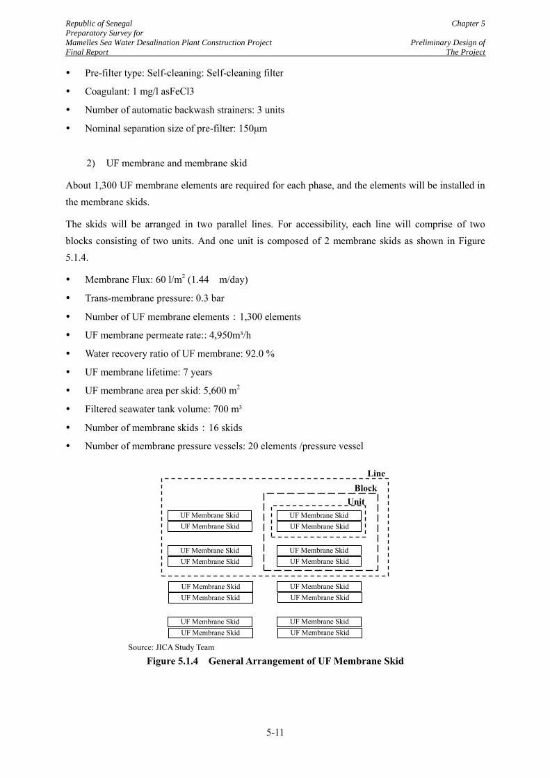
Republic of Senegal Chapter 5
Preparatory Survey for
Mamelles Sea Water Desalination Plant Construction Project Preliminary Design of
Final Report The Project
5-11
Pre-filter type: Self-cleaning: Self-cleaning filter
Coagulant: 1 mg/l asFeCl3
Number of automatic backwash strainers: 3 units
Nominal separation size of pre-filter: 150μm
2) UF membrane and membrane skid
About 1,300 UF membrane elements are required for each phase, and the elements will be installed in the membrane skids.
The skids will be arranged in two parallel lines. For accessibility, each line will comprise of two blocks consisting of two units. And one unit is composed of 2 membrane skids as shown in Figure 5.1.4.
Membrane Flux: 60 l/m2 (1.44 m/day)
Trans-membrane pressure: 0.3 bar
Number of UF membrane elements:1,300 elements
UF membrane permeate rate:: 4,950m³/h
Water recovery ratio of UF membrane: 92.0 %
UF membrane lifetime: 7 years
UF membrane area per skid: 5,600 m2
Filtered seawater tank volume: 700 m³
Number of membrane skids:16 skids
Number of membrane pressure vessels: 20 elements /pressure vessel
Source: JICA Study Team
Figure 5.1.4 General Arrangement of UF Membrane Skid
UF Membrane Skid UF Membrane Skid
UF Membrane Skid UF Membrane Skid
Unit Block
UF Membrane Skid UF Membrane Skid
UF Membrane Skid UF Membrane Skid
UF Membrane Skid UF Membrane Skid
UF Membrane Skid UF Membrane Skid
UF Membrane Skid UF Membrane Skid
UF Membrane Skid UF Membrane Skid
Line
Republic of Senegal Chapter 5
Preparatory Survey for
Mamelles Sea Water Desalination Plant Construction Project Preliminary Design of
Final Report The Project
5-12
3) Backwashing
The filtration performance of the UF membrane is maintained by regularly conducting physical cleaning, namely backwash with filtered water and air cleaning are automatically carried out approximately once every 30 minutes.
In case the membrane performance is not restored by the regular cleaning, chemical cleaning should be implemented to try to maintain filtration performance. Chemical cleaning should be conducted about 1-2 times in a year, using sulphuric acid (H2SO4), hydrochloric acid (HCl), caustic soda (NaOH), chlorinated water (Cl2), organic acids such as citric acid (C6H7O8) under CIP cleaning method. Since chemical cleaning conditions depend on the raw seawater chemistry, verification of the details by field tests is required.
Filtration cycle time: 30 min
Backwash duration: 45 sec
Number of backwash water pumps: 2 units (including one standby)
Capacity of backwash water pumps: 1400 m3/h
Number of chemical washing pumps: 2 units (including one standby)
Capacity of chemical washing pumps: 750 m3/h
(5) Requirements for detail design of the UF membrane process
1) Reference requirements and pilot plant testing
Regarding the suitability of the actual membrane manufacturer selection, the EPC Contractor shall be requested to demonstrate the pilot plant testing to confirm the performance and efficiency of the UF membrane system under site conditions.
Within the project implementation phase, pilot plant testing should be conducted over a minimum period of 4 months, during the most adverse seawater conditions, to confirm the selected pre-treatment process, to verify its efficiency and to optimize the dosing rates of chemicals.
2) Omission of cartridge filters
According to statements from all three relevant membrane manufacturers, it is not necessary to install cartridge filters in front of the reverse osmosis section, provided the UF filtrate is directly used as a feed into the first pass reverse osmosis pressure vessels, i.e. without any break/buffer tank between ultra-filtration units and reverse osmosis trains. In consequence, no cartridge filters are considered for the membrane based pre-treatment.
5.1.3 Design of RO Membrane Section
(1) Conditioning of feed water
The feed water will be conditioned prior to the RO membrane because SrSO4 scale would be precipitated on the RO membrane surface due to the high Strontium concentration in the feed water. It
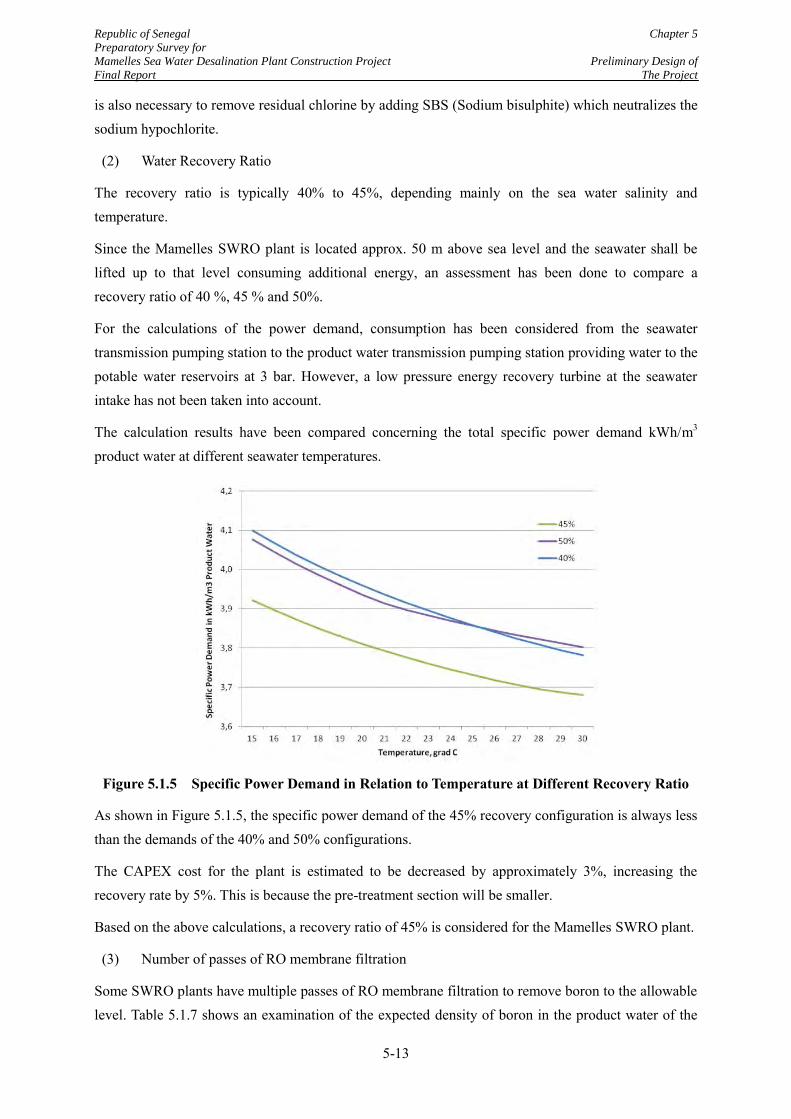
Republic of Senegal Chapter 5
Preparatory Survey for
Mamelles Sea Water Desalination Plant Construction Project Preliminary Design of
Final Report The Project
5-13
is also necessary to remove residual chlorine by adding SBS (Sodium bisulphite) which neutralizes the sodium hypochlorite.
(2) Water Recovery Ratio
The recovery ratio is typically 40% to 45%, depending mainly on the sea water salinity and temperature.
Since the Mamelles SWRO plant is located approx. 50 m above sea level and the seawater shall be lifted up to that level consuming additional energy, an assessment has been done to compare a recovery ratio of 40 %, 45 % and 50%.
For the calculations of the power demand, consumption has been considered from the seawater transmission pumping station to the product water transmission pumping station providing water to the potable water reservoirs at 3 bar. However, a low pressure energy recovery turbine at the seawater intake has not been taken into account.
The calculation results have been compared concerning the total specific power demand kWh/m3 product water at different seawater temperatures.
Figure 5.1.5 Specific Power Demand in Relation to Temperature at Different Recovery Ratio
As shown in Figure 5.1.5, the specific power demand of the 45% recovery configuration is always less than the demands of the 40% and 50% configurations.
The CAPEX cost for the plant is estimated to be decreased by approximately 3%, increasing the recovery rate by 5%. This is because the pre-treatment section will be smaller.
Based on the above calculations, a recovery ratio of 45% is considered for the Mamelles SWRO plant.
(3) Number of passes of RO membrane filtration
Some SWRO plants have multiple passes of RO membrane filtration to remove boron to the allowable level. Table 5.1.7 shows an examination of the expected density of boron in the product water of the
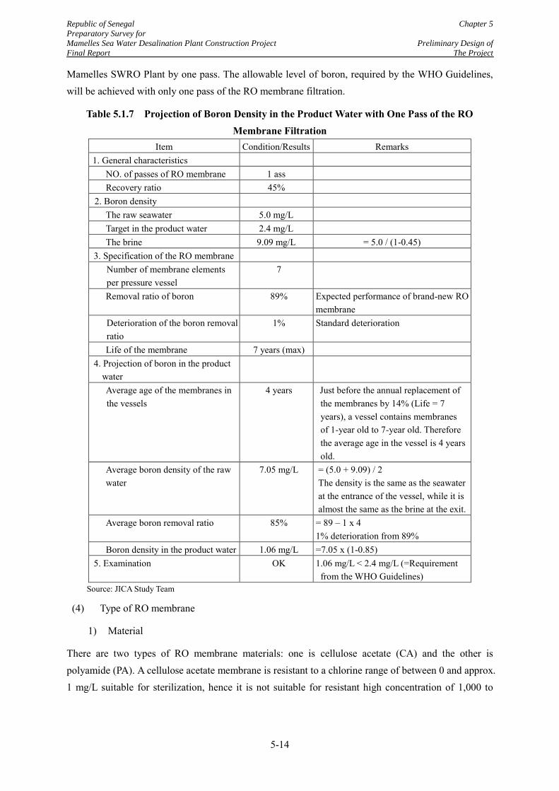
Republic of Senegal Chapter 5
Preparatory Survey for
Mamelles Sea Water Desalination Plant Construction Project Preliminary Design of
Final Report The Project
5-14
Mamelles SWRO Plant by one pass. The allowable level of boron, required by the WHO Guidelines, will be achieved with only one pass of the RO membrane filtration.
Table 5.1.7 Projection of Boron Density in the Product Water with One Pass of the RO Membrane Filtration
Item Condition/Results Remarks 1. General characteristics
NO. of passes of RO membrane 1 ass Recovery ratio 45%
2. Boron density The raw seawater 5.0 mg/L Target in the product water 2.4 mg/L The brine 9.09 mg/L = 5.0 / (1-0.45)
3. Specification of the RO membrane Number of membrane elements per pressure vessel
7
Removal ratio of boron 89% Expected performance of brand-new RO membrane
Deterioration of the boron removal ratio
1% Standard deterioration
Life of the membrane 7 years (max) 4. Projection of boron in the product
water
Average age of the membranes in the vessels
4 years Just before the annual replacement of the membranes by 14% (Life = 7 years), a vessel contains membranes of 1-year old to 7-year old. Therefore the average age in the vessel is 4 years old.
Average boron density of the raw water
7.05 mg/L = (5.0 + 9.09) / 2 The density is the same as the seawater at the entrance of the vessel, while it is almost the same as the brine at the exit.
Average boron removal ratio 85% = 89 – 1 x 4 1% deterioration from 89%
Boron density in the product water 1.06 mg/L =7.05 x (1-0.85) 5. Examination OK 1.06 mg/L < 2.4 mg/L (=Requirement
from the WHO Guidelines) Source: JICA Study Team
(4) Type of RO membrane
1) Material
There are two types of RO membrane materials: one is cellulose acetate (CA) and the other is polyamide (PA). A cellulose acetate membrane is resistant to a chlorine range of between 0 and approx. 1 mg/L suitable for sterilization, hence it is not suitable for resistant high concentration of 1,000 to
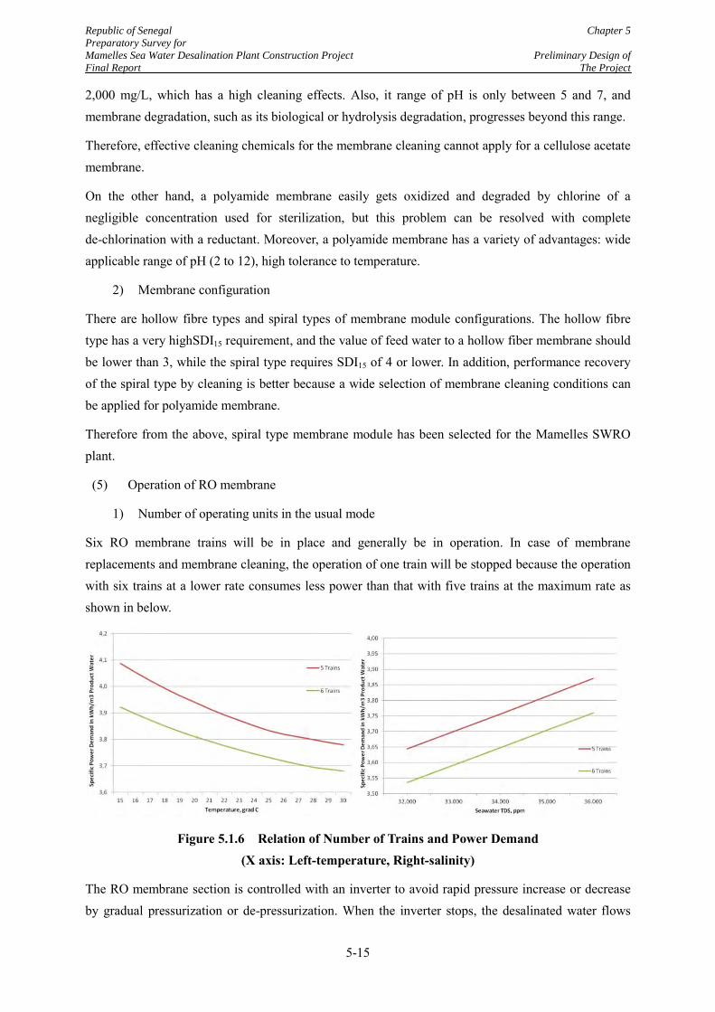
Republic of Senegal Chapter 5
Preparatory Survey for
Mamelles Sea Water Desalination Plant Construction Project Preliminary Design of
Final Report The Project
5-15
2,000 mg/L, which has a high cleaning effects. Also, it range of pH is only between 5 and 7, and membrane degradation, such as its biological or hydrolysis degradation, progresses beyond this range.
Therefore, effective cleaning chemicals for the membrane cleaning cannot apply for a cellulose acetate membrane.
On the other hand, a polyamide membrane easily gets oxidized and degraded by chlorine of a negligible concentration used for sterilization, but this problem can be resolved with complete de-chlorination with a reductant. Moreover, a polyamide membrane has a variety of advantages: wide applicable range of pH (2 to 12), high tolerance to temperature.
2) Membrane configuration
There are hollow fibre types and spiral types of membrane module configurations. The hollow fibre type has a very highSDI15 requirement, and the value of feed water to a hollow fiber membrane should be lower than 3, while the spiral type requires SDI15 of 4 or lower. In addition, performance recovery of the spiral type by cleaning is better because a wide selection of membrane cleaning conditions can be applied for polyamide membrane.
Therefore from the above, spiral type membrane module has been selected for the Mamelles SWRO plant.
(5) Operation of RO membrane
1) Number of operating units in the usual mode
Six RO membrane trains will be in place and generally be in operation. In case of membrane replacements and membrane cleaning, the operation of one train will be stopped because the operation with six trains at a lower rate consumes less power than that with five trains at the maximum rate as shown in below.
Figure 5.1.6 Relation of Number of Trains and Power Demand (X axis: Left-temperature, Right-salinity)
The RO membrane section is controlled with an inverter to avoid rapid pressure increase or decrease by gradual pressurization or de-pressurization. When the inverter stops, the desalinated water flows
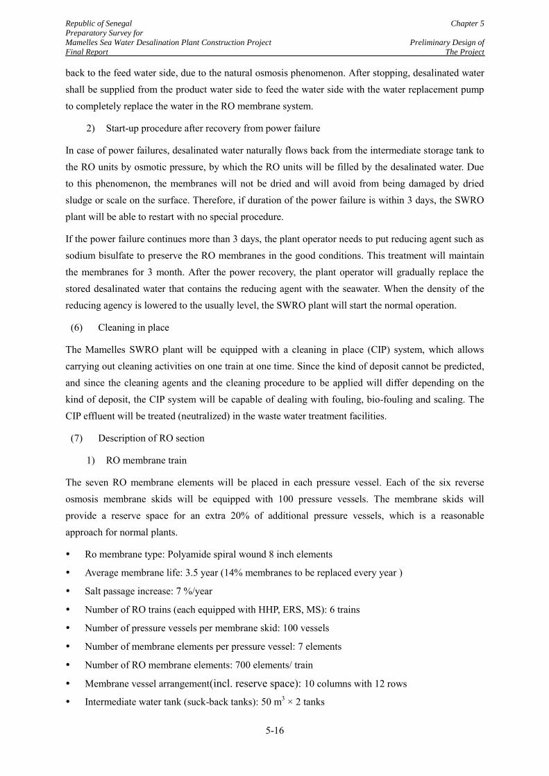
Republic of Senegal Chapter 5
Preparatory Survey for
Mamelles Sea Water Desalination Plant Construction Project Preliminary Design of
Final Report The Project
5-16
back to the feed water side, due to the natural osmosis phenomenon. After stopping, desalinated water shall be supplied from the product water side to feed the water side with the water replacement pump to completely replace the water in the RO membrane system.
2) Start-up procedure after recovery from power failure
In case of power failures, desalinated water naturally flows back from the intermediate storage tank to the RO units by osmotic pressure, by which the RO units will be filled by the desalinated water. Due to this phenomenon, the membranes will not be dried and will avoid from being damaged by dried sludge or scale on the surface. Therefore, if duration of the power failure is within 3 days, the SWRO plant will be able to restart with no special procedure.
If the power failure continues more than 3 days, the plant operator needs to put reducing agent such as sodium bisulfate to preserve the RO membranes in the good conditions. This treatment will maintain the membranes for 3 month. After the power recovery, the plant operator will gradually replace the stored desalinated water that contains the reducing agent with the seawater. When the density of the reducing agency is lowered to the usually level, the SWRO plant will start the normal operation.
(6) Cleaning in place
The Mamelles SWRO plant will be equipped with a cleaning in place (CIP) system, which allows carrying out cleaning activities on one train at one time. Since the kind of deposit cannot be predicted, and since the cleaning agents and the cleaning procedure to be applied will differ depending on the kind of deposit, the CIP system will be capable of dealing with fouling, bio-fouling and scaling. The CIP effluent will be treated (neutralized) in the waste water treatment facilities.
(7) Description of RO section
1) RO membrane train
The seven RO membrane elements will be placed in each pressure vessel. Each of the six reverse osmosis membrane skids will be equipped with 100 pressure vessels. The membrane skids will provide a reserve space for an extra 20% of additional pressure vessels, which is a reasonable approach for normal plants.
Ro membrane type: Polyamide spiral wound 8 inch elements
Average membrane life: 3.5 year (14% membranes to be replaced every year )
Salt passage increase: 7 %/year
Number of RO trains (each equipped with HHP, ERS, MS): 6 trains
Number of pressure vessels per membrane skid: 100 vessels
Number of membrane elements per pressure vessel: 7 elements
Number of RO membrane elements: 700 elements/ train
Membrane vessel arrangement(incl. reserve space): 10 columns with 12 rows
Intermediate water tank (suck-back tanks): 50 m3 × 2 tanks
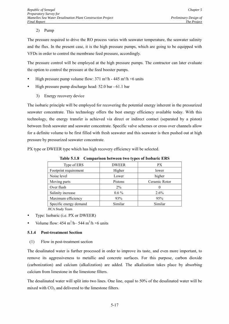
Republic of Senegal Chapter 5
Preparatory Survey for
Mamelles Sea Water Desalination Plant Construction Project Preliminary Design of
Final Report The Project
5-17
2) Pump
The pressure required to drive the RO process varies with seawater temperature, the seawater salinity and the flux. In the present case, it is the high pressure pumps, which are going to be equipped with VFDs in order to control the membrane feed pressure, accordingly.
The pressure control will be employed at the high pressure pumps. The contractor can later evaluate the option to control the pressure at the feed booster pumps.
High pressure pump volume flow: 371 m³/h - 445 m³/h ×6 units
High pressure pump discharge head: 52.0 bar - 61.1 bar
3) Energy recovery device
The isobaric principle will be employed for recovering the potential energy inherent in the pressurized seawater concentrate. This technology offers the best energy efficiency available today. With this technology, the energy transfer is achieved via direct or indirect contact (separated by a piston) between fresh seawater and seawater concentrate. Specific valve schemes or cross over channels allow for a definite volume to be first filled with fresh seawater and this seawater is then pushed out at high pressure by pressurized seawater concentrate.
PX type or DWEER type which has high recovery efficiency will be selected.
Table 5.1.8 Comparison between two types of Isobaric ERS Type of ERS DWEER PX
Footprint requirement Higher lower Noise level Lower higher Moving parts Pistons Ceramic Rotor Over flush 2% 0 Salinity increase 0.6 % 2.6% Maximum efficiency 93% 95% Specific energy demand Similar Similar
JICA Study Team
Type: Isobaric (i.e. PX or DWEER)
Volume flow: 454 m3/h– 544 m3/h ×6 units
5.1.4 Post-treatment Section
(1) Flow in post-treatment section
The desalinated water is further processed in order to improve its taste, and even more important, to remove its aggressiveness to metallic and concrete surfaces. For this purpose, carbon dioxide (carbonization) and calcium (alkalization) are added. The alkalization takes place by absorbing calcium from limestone in the limestone filters.
The desalinated water will split into two lines. One line, equal to 50% of the desalinated water will be mixed with CO2, and delivered to the limestone filters.
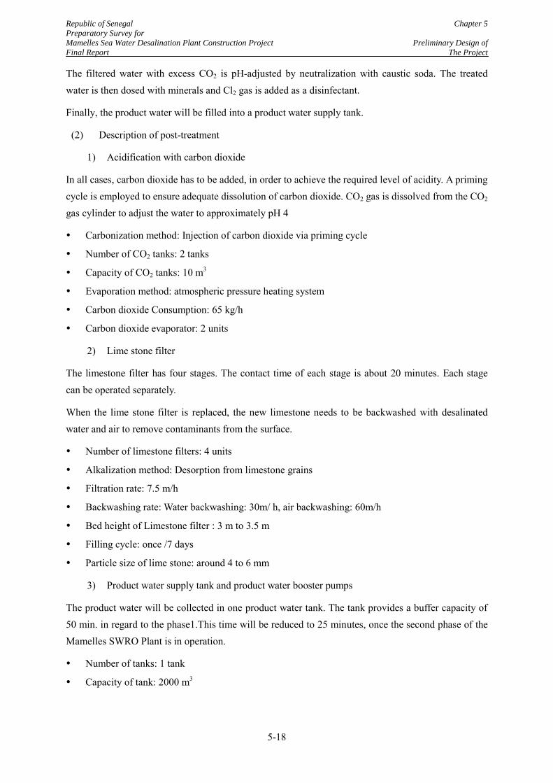
Republic of Senegal Chapter 5
Preparatory Survey for
Mamelles Sea Water Desalination Plant Construction Project Preliminary Design of
Final Report The Project
5-18
The filtered water with excess CO2 is pH-adjusted by neutralization with caustic soda. The treated water is then dosed with minerals and Cl2 gas is added as a disinfectant.
Finally, the product water will be filled into a product water supply tank.
(2) Description of post-treatment
1) Acidification with carbon dioxide
In all cases, carbon dioxide has to be added, in order to achieve the required level of acidity. A priming cycle is employed to ensure adequate dissolution of carbon dioxide. CO2 gas is dissolved from the CO2 gas cylinder to adjust the water to approximately pH 4
Carbonization method: Injection of carbon dioxide via priming cycle
Number of CO2 tanks: 2 tanks
Capacity of CO2 tanks: 10 m3
Evaporation method: atmospheric pressure heating system
Carbon dioxide Consumption: 65 kg/h
Carbon dioxide evaporator: 2 units
2) Lime stone filter
The limestone filter has four stages. The contact time of each stage is about 20 minutes. Each stage can be operated separately.
When the lime stone filter is replaced, the new limestone needs to be backwashed with desalinated water and air to remove contaminants from the surface.
Number of limestone filters: 4 units
Alkalization method: Desorption from limestone grains
Filtration rate: 7.5 m/h
Backwashing rate: Water backwashing: 30m/ h, air backwashing: 60m/h
Bed height of Limestone filter : 3 m to 3.5 m
Filling cycle: once /7 days
Particle size of lime stone: around 4 to 6 mm
3) Product water supply tank and product water booster pumps
The product water will be collected in one product water tank. The tank provides a buffer capacity of 50 min. in regard to the phase1.This time will be reduced to 25 minutes, once the second phase of the Mamelles SWRO Plant is in operation.
Number of tanks: 1 tank
Capacity of tank: 2000 m3
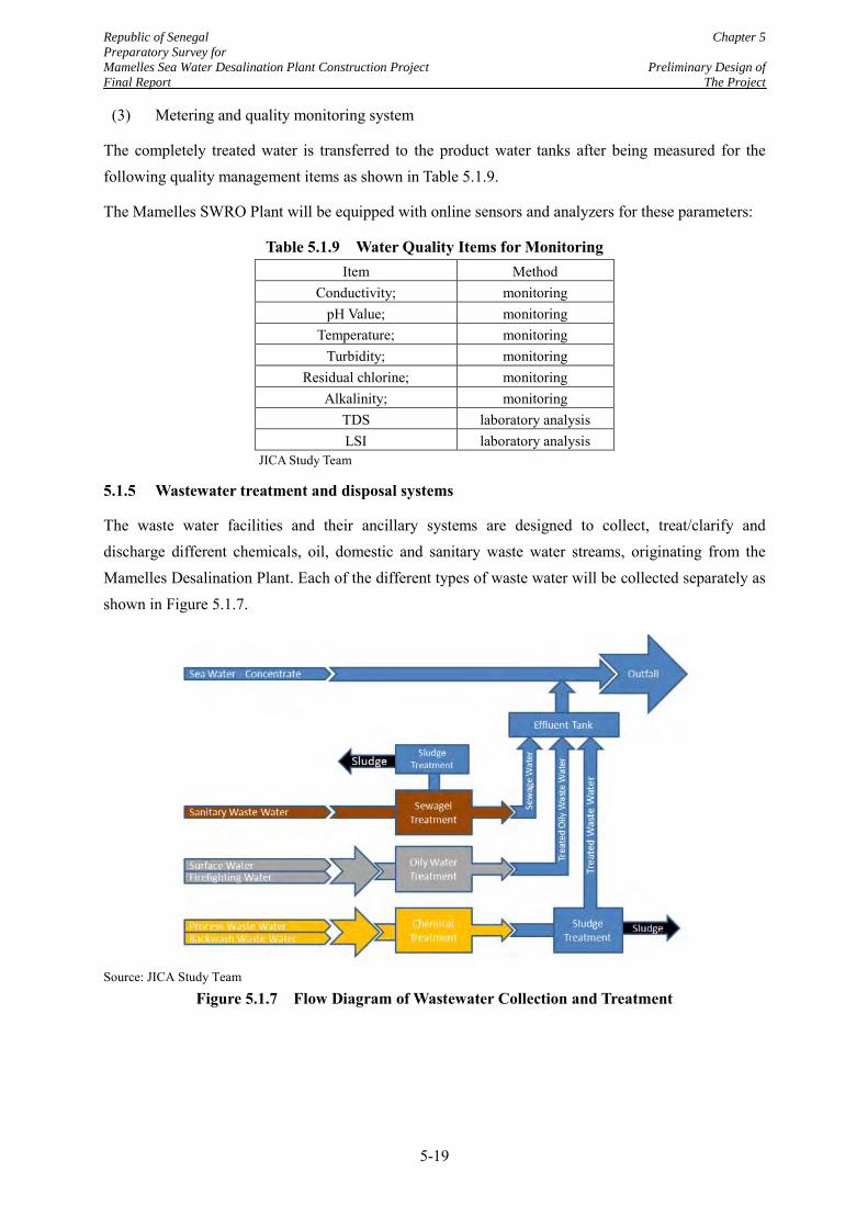
Republic of Senegal Chapter 5
Preparatory Survey for
Mamelles Sea Water Desalination Plant Construction Project Preliminary Design of
Final Report The Project
5-19
(3) Metering and quality monitoring system
The completely treated water is transferred to the product water tanks after being measured for the following quality management items as shown in Table 5.1.9.
The Mamelles SWRO Plant will be equipped with online sensors and analyzers for these parameters:
Table 5.1.9 Water Quality Items for Monitoring Item Method
Conductivity; monitoring pH Value; monitoring
Temperature; monitoring Turbidity; monitoring
Residual chlorine; monitoring Alkalinity; monitoring
TDS laboratory analysis LSI laboratory analysis
JICA Study Team
5.1.5 Wastewater treatment and disposal systems
The waste water facilities and their ancillary systems are designed to collect, treat/clarify and discharge different chemicals, oil, domestic and sanitary waste water streams, originating from the Mamelles Desalination Plant. Each of the different types of waste water will be collected separately as shown in Figure 5.1.7.
Source: JICA Study Team
Figure 5.1.7 Flow Diagram of Wastewater Collection and Treatment
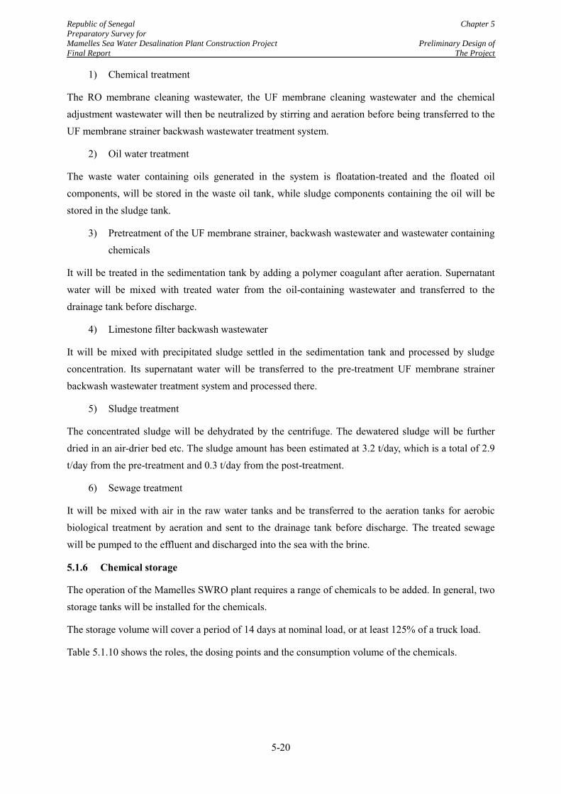
Republic of Senegal Chapter 5
Preparatory Survey for
Mamelles Sea Water Desalination Plant Construction Project Preliminary Design of
Final Report The Project
5-20
1) Chemical treatment
The RO membrane cleaning wastewater, the UF membrane cleaning wastewater and the chemical adjustment wastewater will then be neutralized by stirring and aeration before being transferred to the UF membrane strainer backwash wastewater treatment system.
2) Oil water treatment
The waste water containing oils generated in the system is floatation-treated and the floated oil components, will be stored in the waste oil tank, while sludge components containing the oil will be stored in the sludge tank.
3) Pretreatment of the UF membrane strainer, backwash wastewater and wastewater containing chemicals
It will be treated in the sedimentation tank by adding a polymer coagulant after aeration. Supernatant water will be mixed with treated water from the oil-containing wastewater and transferred to the drainage tank before discharge.
4) Limestone filter backwash wastewater
It will be mixed with precipitated sludge settled in the sedimentation tank and processed by sludge concentration. Its supernatant water will be transferred to the pre-treatment UF membrane strainer backwash wastewater treatment system and processed there.
5) Sludge treatment
The concentrated sludge will be dehydrated by the centrifuge. The dewatered sludge will be further dried in an air-drier bed etc. The sludge amount has been estimated at 3.2 t/day, which is a total of 2.9 t/day from the pre-treatment and 0.3 t/day from the post-treatment.
6) Sewage treatment
It will be mixed with air in the raw water tanks and be transferred to the aeration tanks for aerobic biological treatment by aeration and sent to the drainage tank before discharge. The treated sewage will be pumped to the effluent and discharged into the sea with the brine.
5.1.6 Chemical storage
The operation of the Mamelles SWRO plant requires a range of chemicals to be added. In general, two storage tanks will be installed for the chemicals.
The storage volume will cover a period of 14 days at nominal load, or at least 125% of a truck load.
Table 5.1.10 shows the roles, the dosing points and the consumption volume of the chemicals.
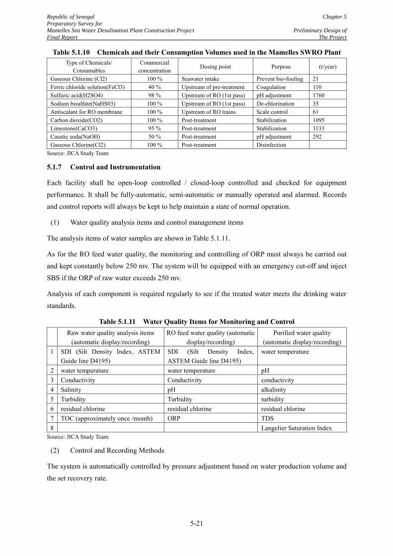
Republic of Senegal Chapter 5
Preparatory Survey for
Mamelles Sea Water Desalination Plant Construction Project Preliminary Design of
Final Report The Project
5-21
Table 5.1.10 Chemicals and their Consumption Volumes used in the Mamelles SWRO Plant Type of Chemicals/
Consumables Commercial
concentration Dosing point Purpose (t/year)
Gaseous Chlorine (Cl2) 100 % Seawater intake Prevent bio-fouling 21 Ferric chloride solution(FeCl3) 40 % Upstream of pre-treatment Coagulation 110 Sulfuric acid(H2SO4) 98 % Upstream of RO (1st pass) pH adjustment 1760 Sodium bisulfate(NaHS03) 100 % Upstream of RO (1st pass) De-chlorination 35 Antiscalant for RO membrane 100 % Upstream of RO trains Scale control 61 Carbon dioxide(CO2) 100 % Post-treatment Stabilization 1095 Limestone(CaCO3) 95 % Post-treatment Stabilization 1133 Caustic soda(NaOH) 50 % Post-treatment pH adjustment 292 Gaseous Chlorine(Cl2) 100 % Post-treatment Disinfection
Source: JICA Study Team
5.1.7 Control and Instrumentation
Each facility shall be open-loop controlled / closed-loop controlled and checked for equipment performance. It shall be fully-automatic, semi-automatic or manually operated and alarmed. Records and control reports will always be kept to help maintain a state of normal operation.
(1) Water quality analysis items and control management items
The analysis items of water samples are shown in Table 5.1.11.
As for the RO feed water quality, the monitoring and controlling of ORP must always be carried out and kept constantly below 250 mv. The system will be equipped with an emergency cut-off and inject SBS if the ORP of raw water exceeds 250 mv.
Analysis of each component is required regularly to see if the treated water meets the drinking water standards.
Table 5.1.11 Water Quality Items for Monitoring and Control Raw water quality analysis items
(automatic display/recording) RO feed water quality (automatic
display/recording) Purified water quality
(automatic display/recording) 1 SDI (Silt Density Index, ASTEM
Guide line D4195) SDI (Silt Density Index, ASTEM Guide line D4195)
water temperature
2 water temperature water temperature pH 3 Conductivity Conductivity conductivity 4 Salinity pH alkalinity 5 Turbidity Turbidity turbidity 6 residual chlorine residual chlorine residual chlorine 7 TOC (approximately once /month) ORP TDS 8 Langelier Saturation Index
Source: JICA Study Team
(2) Control and Recording Methods
The system is automatically controlled by pressure adjustment based on water production volume and the set recovery rate.
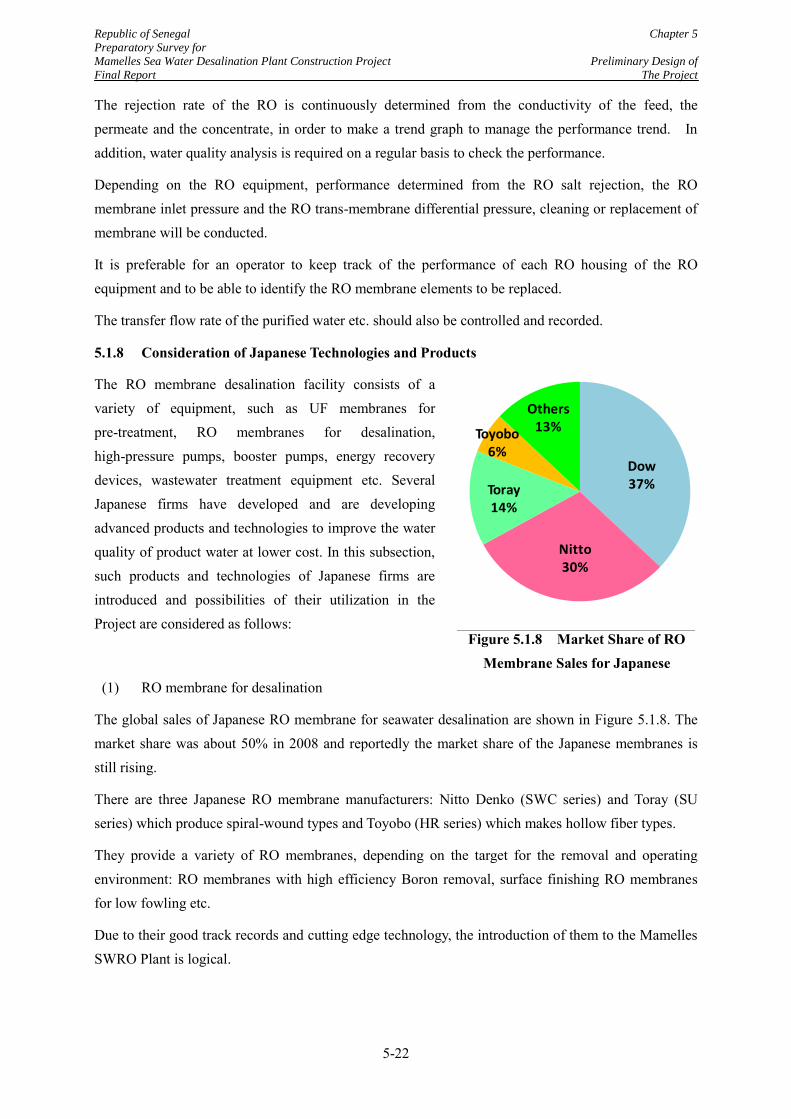
Republic of Senegal Chapter 5
Preparatory Survey for
Mamelles Sea Water Desalination Plant Construction Project Preliminary Design of
Final Report The Project
5-22
Source: Fuji Keizai
Figure 5.1.8 Market Share of RO Membrane Sales for Japanese
Dow37%
Nitto30%
Toray14%
Toyobo 6%
Others13%
グラフ タイトル
The rejection rate of the RO is continuously determined from the conductivity of the feed, the permeate and the concentrate, in order to make a trend graph to manage the performance trend. In addition, water quality analysis is required on a regular basis to check the performance.
Depending on the RO equipment, performance determined from the RO salt rejection, the RO membrane inlet pressure and the RO trans-membrane differential pressure, cleaning or replacement of membrane will be conducted.
It is preferable for an operator to keep track of the performance of each RO housing of the RO equipment and to be able to identify the RO membrane elements to be replaced.
The transfer flow rate of the purified water etc. should also be controlled and recorded.
5.1.8 Consideration of Japanese Technologies and Products
The RO membrane desalination facility consists of a variety of equipment, such as UF membranes for pre-treatment, RO membranes for desalination, high-pressure pumps, booster pumps, energy recovery devices, wastewater treatment equipment etc. Several Japanese firms have developed and are developing advanced products and technologies to improve the water quality of product water at lower cost. In this subsection, such products and technologies of Japanese firms are introduced and possibilities of their utilization in the Project are considered as follows:
(1) RO membrane for desalination
The global sales of Japanese RO membrane for seawater desalination are shown in Figure 5.1.8. The market share was about 50% in 2008 and reportedly the market share of the Japanese membranes is still rising.
There are three Japanese RO membrane manufacturers: Nitto Denko (SWC series) and Toray (SU series) which produce spiral-wound types and Toyobo (HR series) which makes hollow fiber types.
They provide a variety of RO membranes, depending on the target for the removal and operating environment: RO membranes with high efficiency Boron removal, surface finishing RO membranes for low fowling etc.
Due to their good track records and cutting edge technology, the introduction of them to the Mamelles SWRO Plant is logical.
Republic of Senegal Chapter 5
Preparatory Survey for
Mamelles Sea Water Desalination Plant Construction Project Preliminary Design of
Final Report The Project
5-23
(2) UF membrane for pre-treatment
UF membranes manufactured by Sumitomo Electric (PORE FLOW with PTFE membrane)and by Asahi Kasei (Microza of PVDF membrane) give excellent performance in the pre-treatment process for seawater desalination in terms of physical tolerance and chemical stability.
Especially, the UF membranre of Sumitomo Electric, made of PTFE, which is very tolerant to pollution
Therefore, an introduction to the Mamelles SWRO Plant is highly anticipated.
(3) Pumps for seawater desalination
Seawater desalination plants are equipped with various kinds of pumps such as intake pumps, feed pumps, high-pressure pumps, booster pump, transfer pumps etc. It is important to use pumps which have a high resistance to corrosion and a good track record for this application.
Japanese pump manufactures have enough technology for the above requirements. In addition, Kubota and Dengyosha provide all types of pumps.
Especially, Torishima as a Japanese pump manufacturer, has 50% of the market share in the Middle East and 40% global share for seawater desalination pumps. Therefore, the introductions of Japanese pumps are highly recommended.
(4) Plant construction
Mitsubishi Heavy Industries Ltd. and Hitachi have track records with desalination plant construction including the evaporation method and RO membrane method.
Mitsubishi Heavy Industries Ltd .has completed the constructions of more than four plants. Hitachi has been implementing the SWRO plant construction project under a DBO contract in Iraq.
(5) New seawater desalination technology with the RO membranes method in Japan
There are challenges regarding the current seawater desalination technologies: reduction of the pollution load generated by chemical contamination and the running costs. The following advanced technologies are being developed in Japan especially for the reduction of power consumption and construction cost:
1) Energy recovery device (ERD)
There are two types of energy recovery device (ERD) being manufactured in Japan.
A rotary type is produced by Kubota. Its energy recovery efficiency is more than 95%.
In the world, 98 % of recover ratio has been achieved by Energy Recovery, Inc. Therefore Kubota’s technology is almost the world’s best level.
Kubota has been conducting demonstration of the system which combines a high-pressure pump with a booster pump.
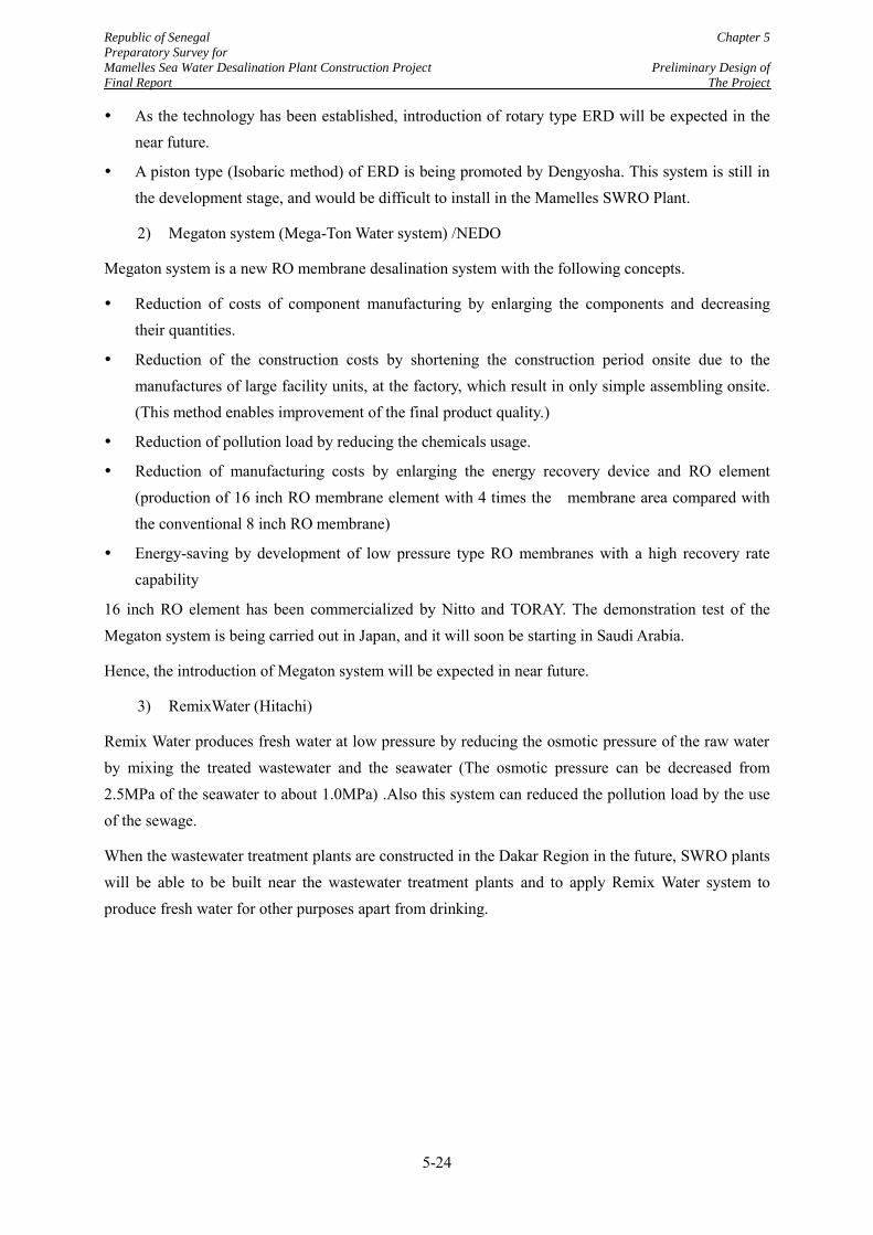
Republic of Senegal Chapter 5
Preparatory Survey for
Mamelles Sea Water Desalination Plant Construction Project Preliminary Design of
Final Report The Project
5-24
As the technology has been established, introduction of rotary type ERD will be expected in the near future.
A piston type (Isobaric method) of ERD is being promoted by Dengyosha. This system is still in the development stage, and would be difficult to install in the Mamelles SWRO Plant.
2) Megaton system (Mega-Ton Water system) /NEDO
Megaton system is a new RO membrane desalination system with the following concepts.
Reduction of costs of component manufacturing by enlarging the components and decreasing their quantities.
Reduction of the construction costs by shortening the construction period onsite due to the manufactures of large facility units, at the factory, which result in only simple assembling onsite. (This method enables improvement of the final product quality.)
Reduction of pollution load by reducing the chemicals usage.
Reduction of manufacturing costs by enlarging the energy recovery device and RO element (production of 16 inch RO membrane element with 4 times the membrane area compared with the conventional 8 inch RO membrane)
Energy-saving by development of low pressure type RO membranes with a high recovery rate capability
16 inch RO element has been commercialized by Nitto and TORAY. The demonstration test of the Megaton system is being carried out in Japan, and it will soon be starting in Saudi Arabia.
Hence, the introduction of Megaton system will be expected in near future.
3) RemixWater (Hitachi)
Remix Water produces fresh water at low pressure by reducing the osmotic pressure of the raw water by mixing the treated wastewater and the seawater (The osmotic pressure can be decreased from 2.5MPa of the seawater to about 1.0MPa) .Also this system can reduced the pollution load by the use of the sewage.
When the wastewater treatment plants are constructed in the Dakar Region in the future, SWRO plants will be able to be built near the wastewater treatment plants and to apply Remix Water system to produce fresh water for other purposes apart from drinking.
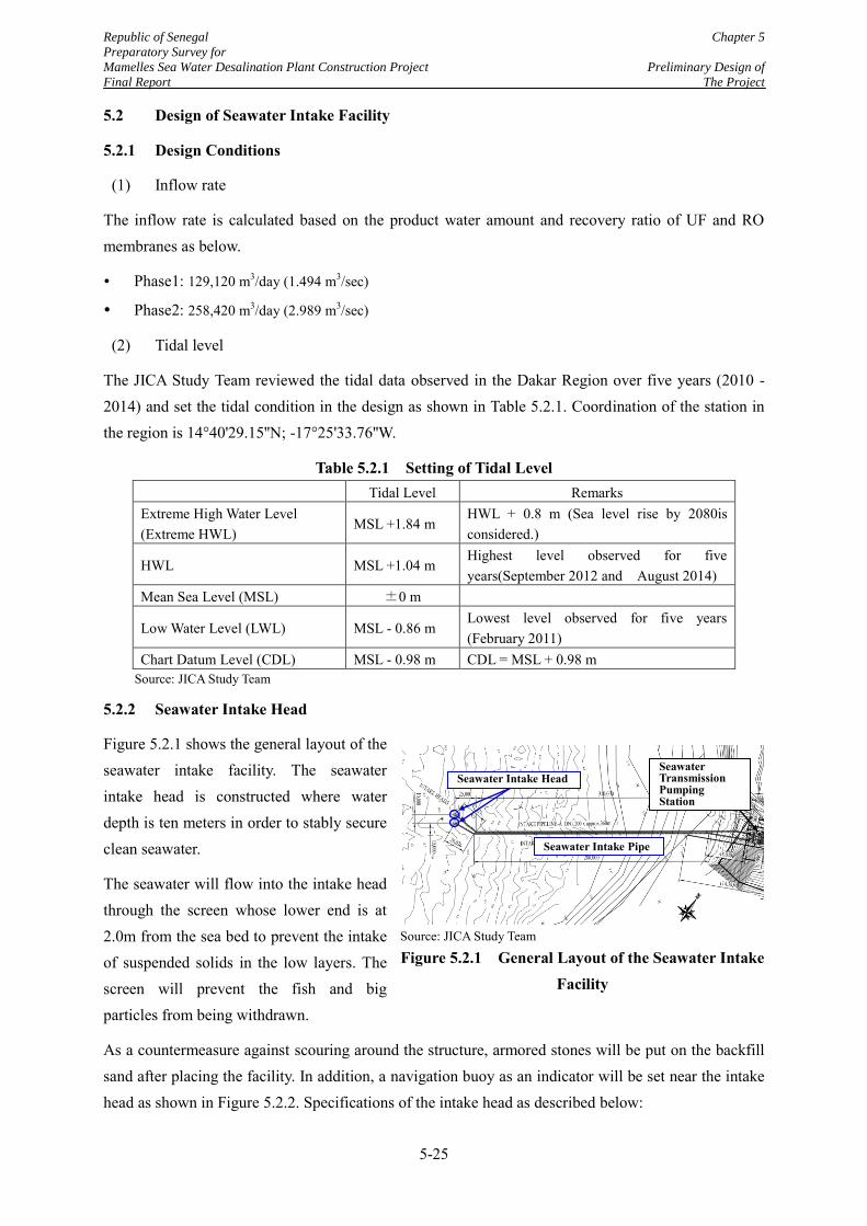
Republic of Senegal Chapter 5
Preparatory Survey for
Mamelles Sea Water Desalination Plant Construction Project Preliminary Design of
Final Report The Project
5-25
5.2 Design of Seawater Intake Facility
5.2.1 Design Conditions
(1) Inflow rate
The inflow rate is calculated based on the product water amount and recovery ratio of UF and RO membranes as below.
Phase1: 129,120 m3/day (1.494 m3/sec)
Phase2: 258,420 m3/day (2.989 m3/sec)
(2) Tidal level
The JICA Study Team reviewed the tidal data observed in the Dakar Region over five years (2010 - 2014) and set the tidal condition in the design as shown in Table 5.2.1. Coordination of the station in the region is 14°40'29.15''N; -17°25'33.76''W.
Table 5.2.1 Setting of Tidal Level Tidal Level Remarks
Extreme High Water Level (Extreme HWL)
MSL +1.84 m HWL + 0.8 m (Sea level rise by 2080is considered.)
HWL MSL +1.04 m Highest level observed for five years(September 2012 and August 2014)
Mean Sea Level (MSL) ±0 m
Low Water Level (LWL) MSL - 0.86 m Lowest level observed for five years (February 2011)
Chart Datum Level (CDL) MSL - 0.98 m CDL = MSL + 0.98 m Source: JICA Study Team
5.2.2 Seawater Intake Head
Figure 5.2.1 shows the general layout of the seawater intake facility. The seawater intake head is constructed where water depth is ten meters in order to stably secure clean seawater.
The seawater will flow into the intake head through the screen whose lower end is at 2.0m from the sea bed to prevent the intake of suspended solids in the low layers. The screen will prevent the fish and big particles from being withdrawn.
As a countermeasure against scouring around the structure, armored stones will be put on the backfill sand after placing the facility. In addition, a navigation buoy as an indicator will be set near the intake head as shown in Figure 5.2.2. Specifications of the intake head as described below:
Source: JICA Study Team
Figure 5.2.1 General Layout of the Seawater Intake Facility
Seawater Intake Head
Seawater Intake Pipe
Seawater Transmission Pumping Station
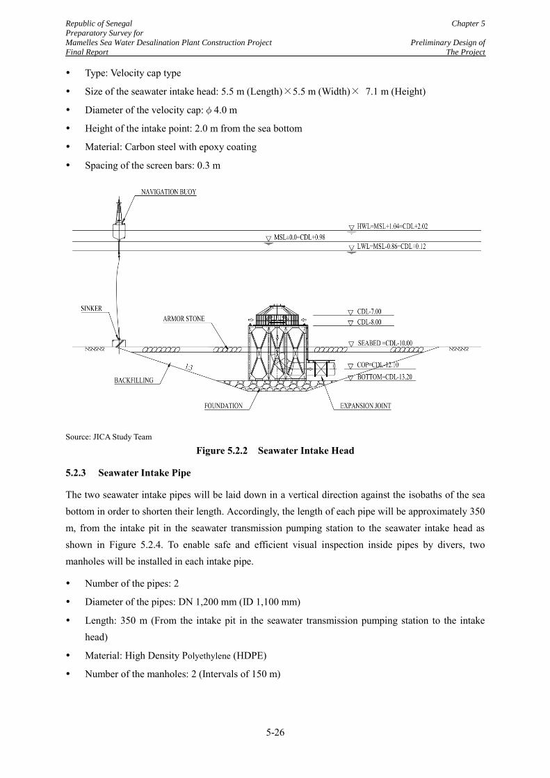
Republic of Senegal Chapter 5
Preparatory Survey for
Mamelles Sea Water Desalination Plant Construction Project Preliminary Design of
Final Report The Project
5-26
Type: Velocity cap type
Size of the seawater intake head: 5.5 m (Length)×5.5 m (Width)× 7.1 m (Height)
Diameter of the velocity cap:φ4.0 m
Height of the intake point: 2.0 m from the sea bottom
Material: Carbon steel with epoxy coating
Spacing of the screen bars: 0.3 m
Source: JICA Study Team
Figure 5.2.2 Seawater Intake Head
5.2.3 Seawater Intake Pipe
The two seawater intake pipes will be laid down in a vertical direction against the isobaths of the sea bottom in order to shorten their length. Accordingly, the length of each pipe will be approximately 350 m, from the intake pit in the seawater transmission pumping station to the seawater intake head as shown in Figure 5.2.4. To enable safe and efficient visual inspection inside pipes by divers, two manholes will be installed in each intake pipe.
Number of the pipes: 2
Diameter of the pipes: DN 1,200 mm (ID 1,100 mm)
Length: 350 m (From the intake pit in the seawater transmission pumping station to the intake head)
Material: High Density Polyethylene (HDPE)
Number of the manholes: 2 (Intervals of 150 m)
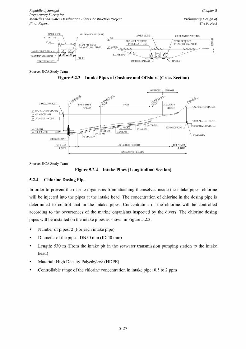
Republic of Senegal Chapter 5
Preparatory Survey for
Mamelles Sea Water Desalination Plant Construction Project Preliminary Design of
Final Report The Project
5-27
Source: JICA Study Team
Figure 5.2.3 Intake Pipes at Onshore and Offshore (Cross Section)
Source: JICA Study Team
Figure 5.2.4 Intake Pipes (Longitudinal Section)
5.2.4 Chlorine Dosing Pipe
In order to prevent the marine organisms from attaching themselves inside the intake pipes, chlorine will be injected into the pipes at the intake head. The concentration of chlorine in the dosing pipe is determined to control that in the intake pipes. Concentration of the chlorine will be controlled according to the occurrences of the marine organisms inspected by the divers. The chlorine dosing pipes will be installed on the intake pipes as shown in Figure 5.2.3.
Number of pipes: 2 (For each intake pipe)
Diameter of the pipes: DN50 mm (ID 40 mm)
Length: 530 m (From the intake pit in the seawater transmission pumping station to the intake head)
Material: High Density Polyethylene (HDPE)
Controllable range of the chlorine concentration in intake pipe: 0.5 to 2 ppm
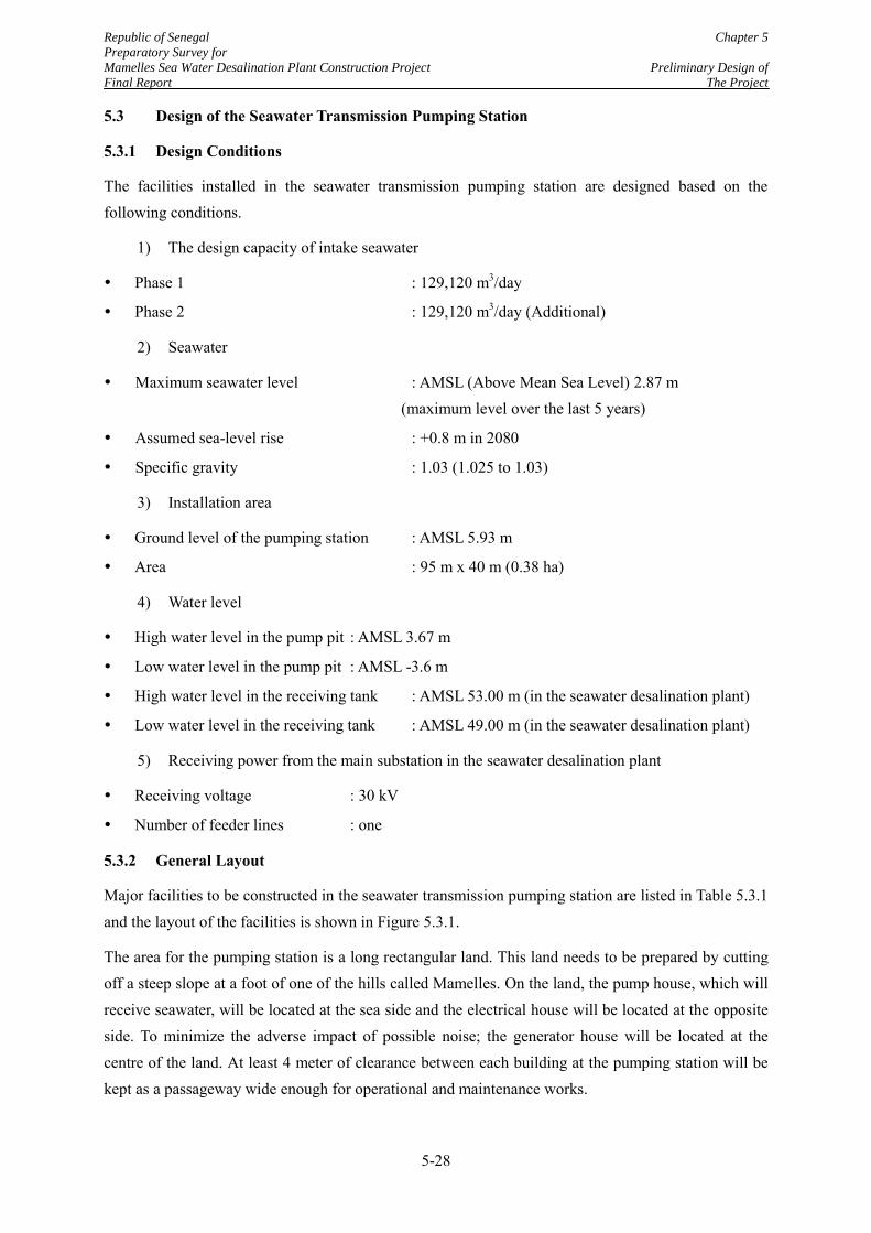
Republic of Senegal Chapter 5
Preparatory Survey for
Mamelles Sea Water Desalination Plant Construction Project Preliminary Design of
Final Report The Project
5-28
5.3 Design of the Seawater Transmission Pumping Station
5.3.1 Design Conditions
The facilities installed in the seawater transmission pumping station are designed based on the following conditions.
1) The design capacity of intake seawater
Phase 1 : 129,120 m3/day
Phase 2 : 129,120 m3/day (Additional)
2) Seawater
Maximum seawater level : AMSL (Above Mean Sea Level) 2.87 m (maximum level over the last 5 years)
Assumed sea-level rise : +0.8 m in 2080
Specific gravity : 1.03 (1.025 to 1.03)
3) Installation area
Ground level of the pumping station : AMSL 5.93 m
Area : 95 m x 40 m (0.38 ha)
4) Water level
High water level in the pump pit : AMSL 3.67 m
Low water level in the pump pit : AMSL -3.6 m
High water level in the receiving tank : AMSL 53.00 m (in the seawater desalination plant)
Low water level in the receiving tank : AMSL 49.00 m (in the seawater desalination plant)
5) Receiving power from the main substation in the seawater desalination plant
Receiving voltage : 30 kV
Number of feeder lines : one
5.3.2 General Layout
Major facilities to be constructed in the seawater transmission pumping station are listed in Table 5.3.1 and the layout of the facilities is shown in Figure 5.3.1.
The area for the pumping station is a long rectangular land. This land needs to be prepared by cutting off a steep slope at a foot of one of the hills called Mamelles. On the land, the pump house, which will receive seawater, will be located at the sea side and the electrical house will be located at the opposite side. To minimize the adverse impact of possible noise; the generator house will be located at the centre of the land. At least 4 meter of clearance between each building at the pumping station will be kept as a passageway wide enough for operational and maintenance works.
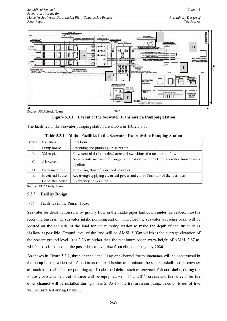
Republic of Senegal Chapter 5
Preparatory Survey for
Mamelles Sea Water Desalination Plant Construction Project Preliminary Design of
Final Report The Project
5-29
Source: JICA Study Team
Figure 5.3.1 Layout of the Seawater Transmission Pumping Station
The facilities in the seawater pumping station are shown in Table 5.3.1.
Table 5.3.1 Major Facilities in the Seawater Transmission Pumping Station Code Facilities Functions
A Pump house Screening and pumping up seawater B Valve pit Flow control for brine discharge and switching of transmission flow
C Air vessel As a countermeasure for surge suppression to protect the seawater transmission pipeline
D Flow meter pit Measuring flow of brine and seawater E Electrical house Receiving/supplying electrical power and control/monitor of the facilities F Generator house Emergency power supply
Source: JICA Study Team
5.3.3 Facility Design
(1) Facilities in the Pump House
Seawater for desalination runs by gravity flow in the intake pipes laid down under the seabed, into the receiving basin in the seawater intake pumping station. Therefore the seawater receiving basin will be located on the sea side of the land for the pumping station to make the depth of the structure as shallow as possible. Ground level of the land will be AMSL 5.93m which is the average elevation of the present ground level. It is 2.26 m higher than the maximum ocean wave height of AMSL 3.67 m, which takes into account the possible sea-level rise from climate change by 2080.
As shown in Figure 5.3.2, three channels including one channel for maintenance will be constructed in the pump house, which will function as removal basins to eliminate the sand/seashell in the seawater as much as possible before pumping up. To clear off debris such as seaweed, fish and shells, during the Phase1, two channels out of three will be equipped with 1st and 2nd screens and the screens for the other channel will be installed during Phase 2. As for the transmission pump, three units out of five will be installed during Phase 1.
A
B
C
D
E
F
98m
40m
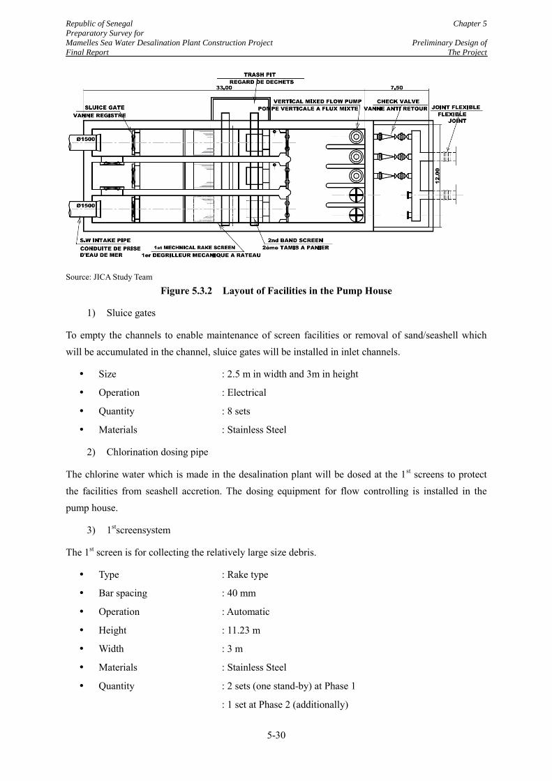
Republic of Senegal Chapter 5
Preparatory Survey for
Mamelles Sea Water Desalination Plant Construction Project Preliminary Design of
Final Report The Project
5-30
Source: JICA Study Team
Figure 5.3.2 Layout of Facilities in the Pump House
1) Sluice gates
To empty the channels to enable maintenance of screen facilities or removal of sand/seashell which will be accumulated in the channel, sluice gates will be installed in inlet channels.
Size : 2.5 m in width and 3m in height
Operation : Electrical
Quantity : 8 sets
Materials : Stainless Steel
2) Chlorination dosing pipe
The chlorine water which is made in the desalination plant will be dosed at the 1st screens to protect the facilities from seashell accretion. The dosing equipment for flow controlling is installed in the pump house.
3) 1stscreensystem
The 1st screen is for collecting the relatively large size debris.
Type : Rake type
Bar spacing : 40 mm
Operation : Automatic
Height : 11.23 m
Width : 3 m
Materials : Stainless Steel
Quantity : 2 sets (one stand-by) at Phase 1
: 1 set at Phase 2 (additionally)
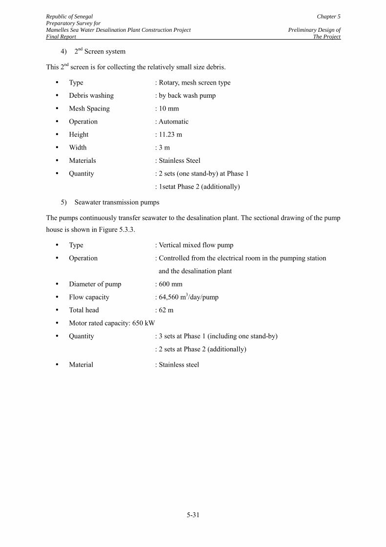
Republic of Senegal Chapter 5
Preparatory Survey for
Mamelles Sea Water Desalination Plant Construction Project Preliminary Design of
Final Report The Project
5-31
4) 2nd Screen system
This 2nd screen is for collecting the relatively small size debris.
Type : Rotary, mesh screen type
Debris washing : by back wash pump
Mesh Spacing : 10 mm
Operation : Automatic
Height : 11.23 m
Width : 3 m
Materials : Stainless Steel
Quantity : 2 sets (one stand-by) at Phase 1
: 1setat Phase 2 (additionally)
5) Seawater transmission pumps
The pumps continuously transfer seawater to the desalination plant. The sectional drawing of the pump house is shown in Figure 5.3.3.
Type : Vertical mixed flow pump
Operation : Controlled from the electrical room in the pumping station
and the desalination plant
Diameter of pump : 600 mm
Flow capacity : 64,560 m3/day/pump
Total head : 62 m
Motor rated capacity: 650 kW
Quantity : 3 sets at Phase 1 (including one stand-by)
: 2 sets at Phase 2 (additionally)
Material : Stainless steel
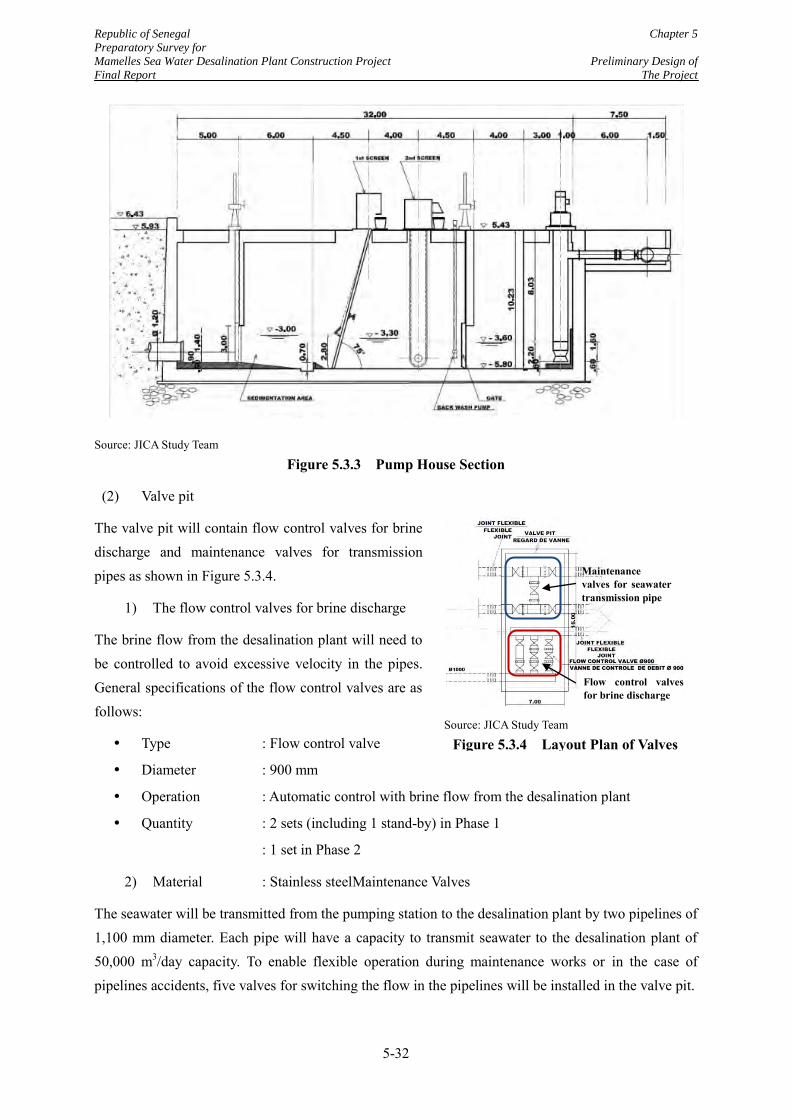
Republic of Senegal Chapter 5
Preparatory Survey for
Mamelles Sea Water Desalination Plant Construction Project Preliminary Design of
Final Report The Project
5-32
Source: JICA Study Team
Figure 5.3.3 Pump House Section
(2) Valve pit
The valve pit will contain flow control valves for brine discharge and maintenance valves for transmission pipes as shown in Figure 5.3.4.
1) The flow control valves for brine discharge
The brine flow from the desalination plant will need to be controlled to avoid excessive velocity in the pipes. General specifications of the flow control valves are as follows:
Type : Flow control valve
Diameter : 900 mm
Operation : Automatic control with brine flow from the desalination plant
Quantity : 2 sets (including 1 stand-by) in Phase 1
: 1 set in Phase 2
2) Material : Stainless steelMaintenance Valves
The seawater will be transmitted from the pumping station to the desalination plant by two pipelines of 1,100 mm diameter. Each pipe will have a capacity to transmit seawater to the desalination plant of 50,000 m3/day capacity. To enable flexible operation during maintenance works or in the case of pipelines accidents, five valves for switching the flow in the pipelines will be installed in the valve pit.
Source: JICA Study Team
Figure 5.3.4 Layout Plan of Valves
Flow control valves for brine discharge
Maintenance valves for seawater transmission pipe
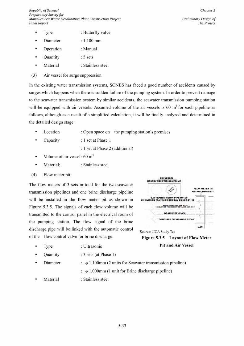
Republic of Senegal Chapter 5
Preparatory Survey for
Mamelles Sea Water Desalination Plant Construction Project Preliminary Design of
Final Report The Project
5-33
Type : Butterfly valve
Diameter : 1,100 mm
Operation : Manual
Quantity : 5 sets
Material : Stainless steel
(3) Air vessel for surge suppression
In the existing water transmission systems, SONES has faced a good number of accidents caused by surges which happens when there is sudden failure of the pumping system. In order to prevent damage to the seawater transmission system by similar accidents, the seawater transmission pumping station will be equipped with air vessels. Assumed volume of the air vessels is 60 m3 for each pipeline as follows, although as a result of a simplified calculation, it will be finally analyzed and determined in the detailed design stage:
Location : Open space on the pumping station’s premises
Capacity : 1 set at Phase 1
: 1 set at Phase 2 (additional)
Volume of air vessel : 60 m3
Material; : Stainless steel
(4) Flow meter pit
The flow meters of 3 sets in total for the two seawater transmission pipelines and one brine discharge pipeline will be installed in the flow meter pit as shown in Figure 5.3.5. The signals of each flow volume will be transmitted to the control panel in the electrical room of the pumping station. The flow signal of the brine discharge pipe will be linked with the automatic control of the flow control valve for brine discharge.
Type : Ultrasonic
Quantity : 3 sets (at Phase 1)
Diameter : φ1,100mm (2 units for Seawater transmission pipeline)
: φ1,000mm (1 unit for Brine discharge pipeline)
Material : Stainless steel
Source: JICA Study Tea
Figure 5.3.5 Layout of Flow Meter Pit and Air Vessel
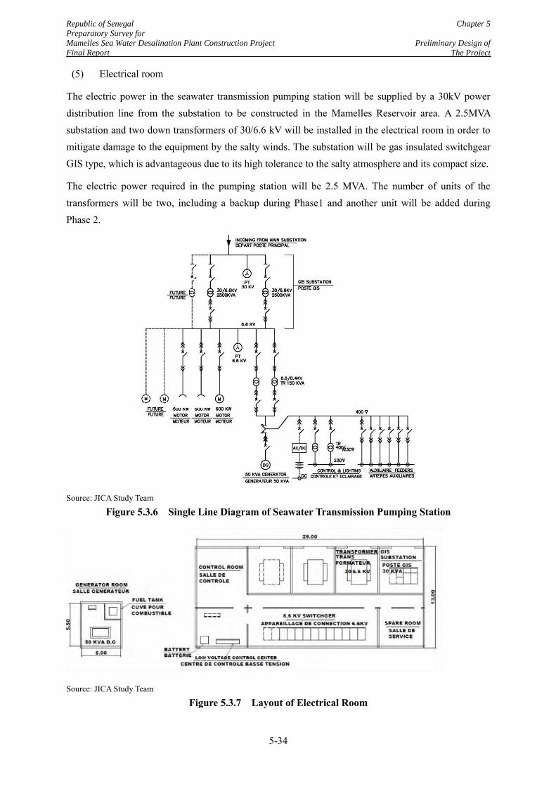
Republic of Senegal Chapter 5
Preparatory Survey for
Mamelles Sea Water Desalination Plant Construction Project Preliminary Design of
Final Report The Project
5-34
(5) Electrical room
The electric power in the seawater transmission pumping station will be supplied by a 30kV power distribution line from the substation to be constructed in the Mamelles Reservoir area. A 2.5MVA substation and two down transformers of 30/6.6 kV will be installed in the electrical room in order to mitigate damage to the equipment by the salty winds. The substation will be gas insulated switchgear GIS type, which is advantageous due to its high tolerance to the salty atmosphere and its compact size.
The electric power required in the pumping station will be 2.5 MVA. The number of units of the transformers will be two, including a backup during Phase1 and another unit will be added during Phase 2.
Source: JICA Study Team
Figure 5.3.6 Single Line Diagram of Seawater Transmission Pumping Station
Source: JICA Study Team
Figure 5.3.7 Layout of Electrical Room
650k
W
moto
rs
Republic of Senegal Chapter 5
Preparatory Survey for
Mamelles Sea Water Desalination Plant Construction Project Preliminary Design of
Final Report The Project
5-35
The single line diagram and layout of the electrical room are shown in Figure 5.3.6 and Figure 5.3.7 respectively.
(6) Generator house
The seawater transmission pumping station will receive the electric power transmitted from the 90/30kV substation on the Mamelles Reservoir premises. High reliability of the 90 kV grids will ensure that very few blackouts will occur and the power supplied will be stable. Therefore, the generator will not need to cover the main pumps but only the following loads for security purposes:
Control power
Instrument
Lighting
Ventilation fans
Air conditioners
Charger for DC power
Supervision
Specification of the generator:
Type : Diesel generator
Capacity : 50 kVA
Starting : Start automatically by blackout signal
Quantity : 1 set
5.3.4 Land Development Design
The pumping station is located 50m away from the seashore, in order to avoid limitation of the recreational activities on the beach, at the foot of one of the hills called “Mamelles”, its top has an altitude of +106 m above mean sea level. Because of the topographic condition, cutting the slope is necessary to secure flat land to construct the pumping station. Plan and cross section of the site of the pumping station are shown in Figure 5.3.8.
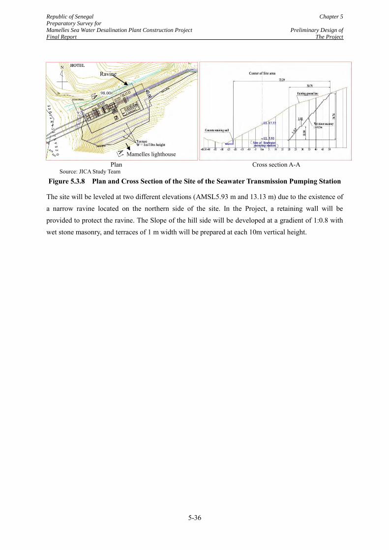
Republic of Senegal Chapter 5
Preparatory Survey for
Mamelles Sea Water Desalination Plant Construction Project Preliminary Design of
Final Report The Project
5-36
Source: JICA Study Team
Figure 5.3.8 Plan and Cross Section of the Site of the Seawater Transmission Pumping Station
The site will be leveled at two different elevations (AMSL5.93 m and 13.13 m) due to the existence of a narrow ravine located on the northern side of the site. In the Project, a retaining wall will be provided to protect the ravine. The Slope of the hill side will be developed at a gradient of 1:0.8 with wet stone masonry, and terraces of 1 m width will be prepared at each 10m vertical height.
Plan Cross section A-A Mamelles lighthouse
Ravine N
98.00
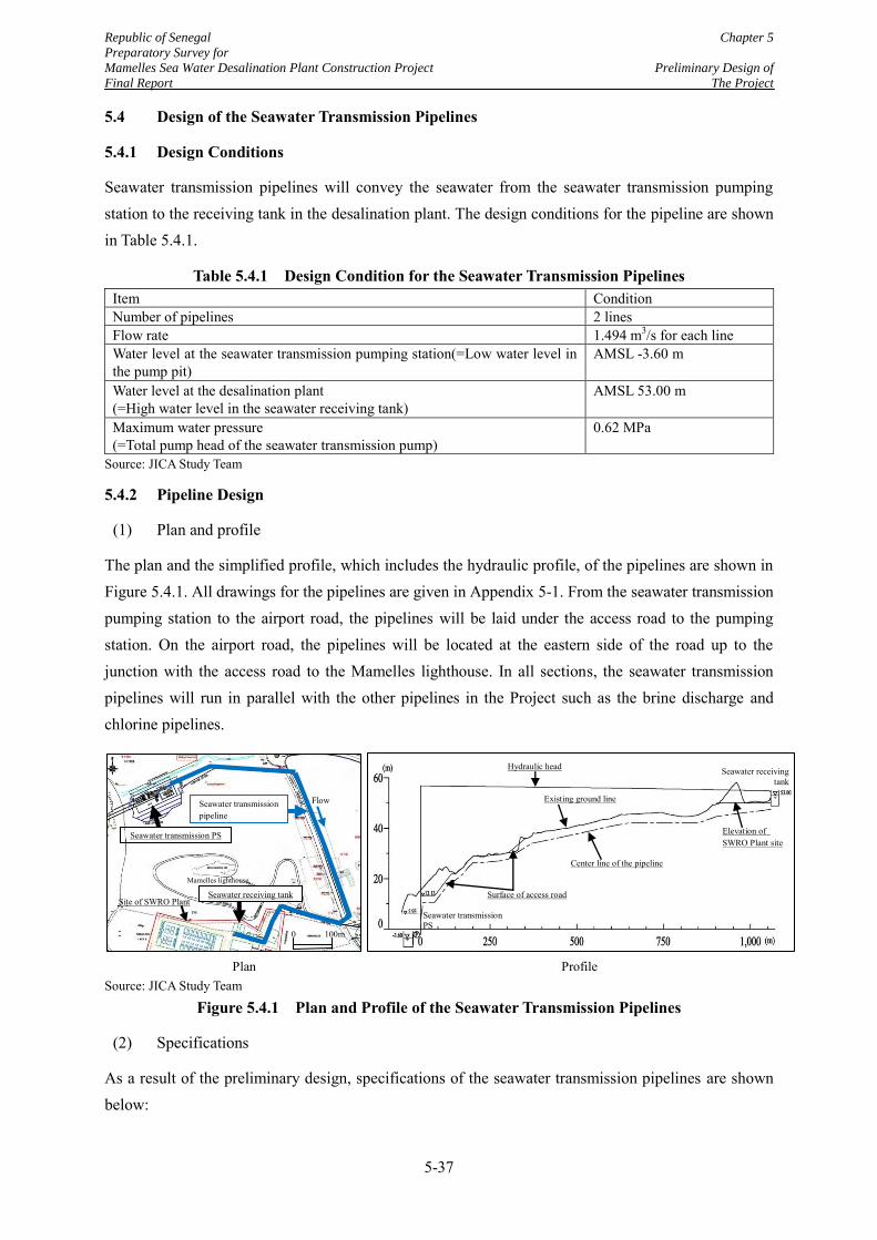
Republic of Senegal Chapter 5
Preparatory Survey for
Mamelles Sea Water Desalination Plant Construction Project Preliminary Design of
Final Report The Project
5-37
5.4 Design of the Seawater Transmission Pipelines
5.4.1 Design Conditions
Seawater transmission pipelines will convey the seawater from the seawater transmission pumping station to the receiving tank in the desalination plant. The design conditions for the pipeline are shown in Table 5.4.1.
Table 5.4.1 Design Condition for the Seawater Transmission Pipelines Item Condition Number of pipelines 2 lines Flow rate 1.494 m3/s for each line Water level at the seawater transmission pumping station(=Low water level in the pump pit)
AMSL -3.60 m
Water level at the desalination plant (=High water level in the seawater receiving tank)
AMSL 53.00 m
Maximum water pressure (=Total pump head of the seawater transmission pump)
0.62 MPa
Source: JICA Study Team
5.4.2 Pipeline Design
(1) Plan and profile
The plan and the simplified profile, which includes the hydraulic profile, of the pipelines are shown in Figure 5.4.1. All drawings for the pipelines are given in Appendix 5-1. From the seawater transmission pumping station to the airport road, the pipelines will be laid under the access road to the pumping station. On the airport road, the pipelines will be located at the eastern side of the road up to the junction with the access road to the Mamelles lighthouse. In all sections, the seawater transmission pipelines will run in parallel with the other pipelines in the Project such as the brine discharge and chlorine pipelines.
Source: JICA Study Team
Figure 5.4.1 Plan and Profile of the Seawater Transmission Pipelines
(2) Specifications
As a result of the preliminary design, specifications of the seawater transmission pipelines are shown below:
Mamelles lighthouse
Plan
Seawater transmission PS
Site of SWRO Plant
Seawater transmission pipeline
Seawater receiving tank
Flow
Seawater transmission PS
Seawater receiving tank
Profile
Existing ground line
Center line of the pipeline
Surface of access road
Elevation of SWRO Plant site
Hydraulic head
0 100m
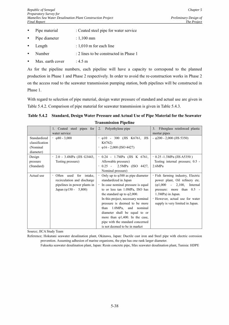
Republic of Senegal Chapter 5
Preparatory Survey for
Mamelles Sea Water Desalination Plant Construction Project Preliminary Design of
Final Report The Project
5-38
Pipe material : Coated steel pipe for water service
Pipe diameter : 1,100 mm
Length : 1,010 m for each line
Number : 2 lines to be constructed in Phase 1
Max. earth cover : 4.5 m
As for the pipeline numbers, each pipeline will have a capacity to correspond to the planned production in Phase 1 and Phase 2 respectively. In order to avoid the re-construction works in Phase 2 on the access road to the seawater transmission pumping station, both pipelines will be constructed in Phase 1.
With regard to selection of pipe material, design water pressure of standard and actual use are given in Table 5.4.2. Comparison of pipe material for seawater transmission is given in Table 5.4.3.
Table 5.4.2 Standard, Design Water Pressure and Actual Use of Pipe Material for the Seawater Transmission Pipeline
1. Coated steel pipes for water service
2. Polyethylene pipe 3. Fiberglass reinforced plastic mortar pipes
Standardized classification (Nominal diameter)
- φ80 - 3,000 - φ10 - 300 (JIS K6761, JIS K6762)
- φ16 - 2,000 (ISO 4427)
- φ200 - 2,000 (JIS 5350)
Design pressure (Standard)
- 2.0 - 3.4MPa (JIS G3443, Testing pressure)
- 0.24 - 1.7MPa (JIS K 6761, Allowable pressure)
- 0.25 - 2.5MPa (ISO 4427, Nominal pressure)
- 0.25 -1.3MPa (JIS A5350 ) Testing internal pressure; 0.5 -
2.6MPa
Actual use - Often used for intake, recirculation and discharge pipelines in power plants in Japan (φ150 - 5,800)
- Only up to φ300 as pipe diameter standardized in Japan
- In case nominal pressure is equal to or less tan 1.0MPa, ISO has the standard up to φ2,000. In this project, necessary nominal pressure is deemed to be more than 1.0MPa, and nominal diameter shall be equal to or more than φ1,400. In the case, pipe with the standard concerned is not deemed to be in market
- Fish farming industry, Electric power plant, Oil refinery etc. (φ1,000 - 2,100, Internal pressure: more than 0.5 - 1.3MPa) in Japan.
- However, actual use for water supply is very limited in Japan.
Source; JICA Study Team Reference; Hokutani seawater desalination plant, Okinawa, Japan: Ductile cast iron and Steel pipe with electric corrosion
prevention. Assuming adhesion of marine organisms, the pipe has one rank larger diameter. Fukuoka seawater desalination plant, Japan: Resin concrete pipe, Sfax seawater desalination plant, Tunisia: HDPE
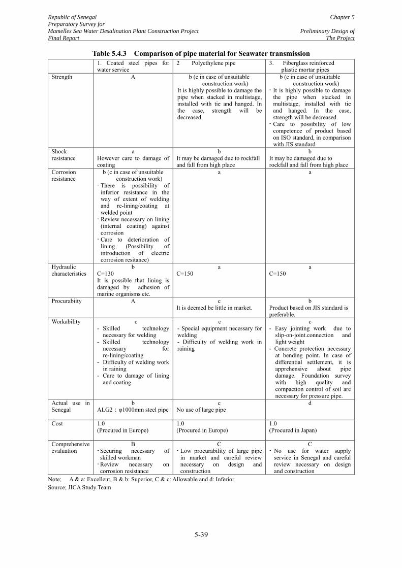
Republic of Senegal Chapter 5
Preparatory Survey for
Mamelles Sea Water Desalination Plant Construction Project Preliminary Design of
Final Report The Project
5-39
Table 5.4.3 Comparison of pipe material for Seawater transmission 1. Coated steel pipes for
water service 2 Polyethylene pipe
3. Fiberglass reinforced plastic mortar pipes
Strength A b (c in case of unsuitable construction work)
It is highly possible to damage the pipe when stacked in multistage, installed with tie and hanged. In the case, strength will be decreased.
b (c in case of unsuitable construction work)
- It is highly possible to damage the pipe when stacked in multistage, installed with tie and hanged. In the case, strength will be decreased.
- Care to possibility of low competence of product based on ISO standard, in comparison with JIS standard
Shock resistance
a However care to damage of coating
b It may be damaged due to rockfall and fall from high place
b It may be damaged due to rockfall and fall from high place
Corrosion resistance
b (c in case of unsuitable construction work)
- There is possibility of inferior resistance in the way of extent of welding and re-lining/coating at welded point
- Review necessary on lining (internal coating) against corrosion
- Care to deterioration of lining (Possibility of introduction of electric corrosion resitance)
a a
Hydraulic characteristics
b C=130 It is possible that lining is damaged by adhesion of marine organisms etc.
a C=150
a C=150
Procurabiity A c It is deemed be little in market.
b Product based on JIS standard is preferable.
Workability c - Skilled technology
necessary for welding - Skilled technology
necessary for re-lining/coating
- Difficulty of welding work in raining
- Care to damage of lining and coating
c - Special equipment necessary for welding - Difficulty of welding work in raining
c - Easy jointing work due to
slip-on-joint.connection and light weight
- Concrete protection necessary at bending point. In case of differential settlement, it is apprehensive about pipe damage. Foundation survey with high quality and compaction control of soil are necessary for pressure pipe.
Actual use in Senegal
b ALG2:φ1000mm steel pipe
c No use of large pipe
d
Cost 1.0 (Procured in Europe)
1.0 (Procured in Europe)
1.0 (Procured in Japan)
Comprehensive evaluation
B - Securing necessary of skilled workman
- Review necessary on corrosion resistance
C - Low procurability of large pipe
in market and careful review necessary on design and construction
C - No use for water supply
service in Senegal and careful review necessary on design and construction
Note; A & a: Excellent, B & b: Superior, C & c: Allowable and d: Inferior Source; JICA Study Team
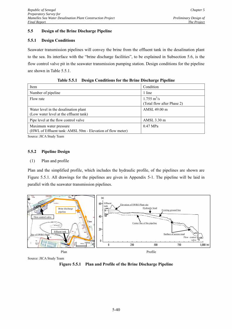
Republic of Senegal Chapter 5
Preparatory Survey for
Mamelles Sea Water Desalination Plant Construction Project Preliminary Design of
Final Report The Project
5-40
5.5 Design of the Brine Discharge Pipeline
5.5.1 Design Conditions
Seawater transmission pipelines will convey the brine from the effluent tank in the desalination plant to the sea. Its interface with the “brine discharge facilities”, to be explained in Subsection 5.6, is the flow control valve pit in the seawater transmission pumping station. Design conditions for the pipeline are shown in Table 5.5.1.
Table 5.5.1 Design Conditions for the Brine Discharge Pipeline Item Condition Number of pipeline 1 line Flow rate 1.755 m3/s
(Total flow after Phase 2) Water level in the desalination plant (Low water level at the effluent tank)
AMSL 49.00 m
Pipe level at the flow control valve AMSL 3.30 m Maximum water pressure (HWL of Effluent tank: AMSL 50m - Elevation of flow meter)
0.47 MPa
Source: JICA Study Team
5.5.2 Pipeline Design
(1) Plan and profile
Plan and the simplified profile, which includes the hydraulic profile, of the pipelines are shown are Figure 5.5.1. All drawings for the pipelines are given in Appendix 5-1. The pipeline will be laid in parallel with the seawater transmission pipelines.
Source: JICA Study Team
Figure 5.5.1 Plan and Profile of the Brine Discharge Pipeline
Effluent tank
Flow control valve
Profile
Existing ground line
Center line of the pipeline
Surface of access road
Elevation of SWRO Plant site Hydraulic head
Plan
Flow
Flow control valve
Site of SWRO Plant
Brine discharge pipeline
Effluent tank
0 100m
Republic of Senegal Chapter 5
Preparatory Survey for
Mamelles Sea Water Desalination Plant Construction Project Preliminary Design of
Final Report The Project
5-41
(2) Specifications
As a result of the preliminary design, specifications of the brine discharge pipeline are shown below:
Pipe material : Coated steel pipe for water service
Pipe diameter : 1,000 mm
Length : 960 m
Number : 1 (common in Phase 1 and 2)
Max. earth cover : 4.5 m
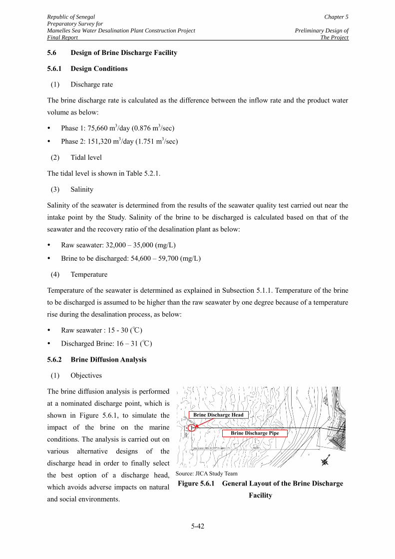
Republic of Senegal Chapter 5
Preparatory Survey for
Mamelles Sea Water Desalination Plant Construction Project Preliminary Design of
Final Report The Project
5-42
5.6 Design of Brine Discharge Facility
5.6.1 Design Conditions
(1) Discharge rate
The brine discharge rate is calculated as the difference between the inflow rate and the product water volume as below:
Phase 1: 75,660 m3/day (0.876 m3/sec)
Phase 2: 151,320 m3/day (1.751 m3/sec)
(2) Tidal level
The tidal level is shown in Table 5.2.1.
(3) Salinity
Salinity of the seawater is determined from the results of the seawater quality test carried out near the intake point by the Study. Salinity of the brine to be discharged is calculated based on that of the seawater and the recovery ratio of the desalination plant as below:
Raw seawater: 32,000 – 35,000 (mg/L)
Brine to be discharged: 54,600 – 59,700 (mg/L)
(4) Temperature
Temperature of the seawater is determined as explained in Subsection 5.1.1. Temperature of the brine to be discharged is assumed to be higher than the raw seawater by one degree because of a temperature rise during the desalination process, as below:
Raw seawater : 15 - 30 (℃)
Discharged Brine: 16 – 31 (℃)
5.6.2 Brine Diffusion Analysis
(1) Objectives
The brine diffusion analysis is performed at a nominated discharge point, which is shown in Figure 5.6.1, to simulate the impact of the brine on the marine conditions. The analysis is carried out on various alternative designs of the discharge head in order to finally select the best option of a discharge head, which avoids adverse impacts on natural and social environments.
Source: JICA Study Team
Figure 5.6.1 General Layout of the Brine Discharge Facility
Brine Discharge Pipe
Brine Discharge Head
Republic of Senegal Chapter 5
Preparatory Survey for
Mamelles Sea Water Desalination Plant Construction Project Preliminary Design of
Final Report The Project
5-43
(2) Analysis conditions
Location of the nominated discharge point: 470m from the shoreline (decided by the bathymetric survey data as explained in Subsection 4.7.4.)
Water depth: CDL (Chart Datum Level) -15 m
Tidal current: Not considered
Brine temperature
For Salinity forecast: 16 ℃, For Velocity forecast: 31 ℃
(Both values above are the strictest conditions in the possible range.)
Salinity
For Salinity forecast: 59.7 (g/L), For Velocity forecast 54.6 (g/L)
(Both values above are the strictest conditions in the possible range)
(3) Goals for the analysis results
Analysis results shall satisfy the following conditions:
The concentration of the brine shall be less than 40 g/L before reaching the seabed to maintain the habitable environment of shoals of white grouper, which is the major commercial fish near the Mamelles area.
The brine with the velocity of 0.25 m/s will not reach the sea surface, to avoid any impact on the traffic of ships or boats.
(4) Methodologies
The diffusion range of the brine is divided into Near-field and Far-field to evaluate the brine impact as shown in Figure 5.6.2, due to the different diffusion characteristics.
Near-field is the area from discharge outlet to the point where the brine reaches the seabed. The diffusion analysis in the area is implemented by Gravity Jet Model, and this model provides the distribution of salinity and velocity of the brine.
Far-field is defined as the outside area of Near-field. Joseph-Sendner’s equation is applied for this area to analyze the horizontal brine diffusion. The results of the forecast in Near-field (flow rate, salinity, thickness of the diffusion layer, etc.) are used as the input data at virtual outlet for the analysis on the horizontal brine diffusion in Far-field.
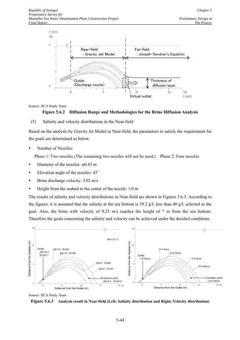
Republic of Senegal Chapter 5
Preparatory Survey for
Mamelles Sea Water Desalination Plant Construction Project Preliminary Design of
Final Report The Project
5-44
Source: JICA Study Team
Figure 5.6.2 Diffusion Range and Methodologies for the Brine Diffusion Analysis
(5) Salinity and velocity distributions in the Near-field
Based on the analysis by Gravity Jet Model in Near-field, the parameters to satisfy the requirement for the goals are determined as below.
Number of Nozzles:
Phase 1: Two nozzles (The remaining two nozzles will not be used.) Phase 2: Four nozzles
Diameter of the nozzles: φ0.43 m
Elevation angle of the nozzles: 45°
Brine discharge velocity: 3.02 m/s
Height from the seabed to the center of the nozzle: 1.0 m
The results of salinity and velocity distributions in Near-field are shown in Figures 5.6.3. According to the figures, it is assumed that the salinity at the sea bottom is 39.2 g/L less than 40 g/L selected as the goal. Also, the brine with velocity of 0.25 m/s reaches the height of 7 m from the sea bottom. Therefore the goals concerning the salinity and velocity can be achieved under the decided conditions.
Source: JICA Study Team
Figure 5.6.3 Analysis result in Near-field (Left; Salinity distribution and Right; Velocity distribution)
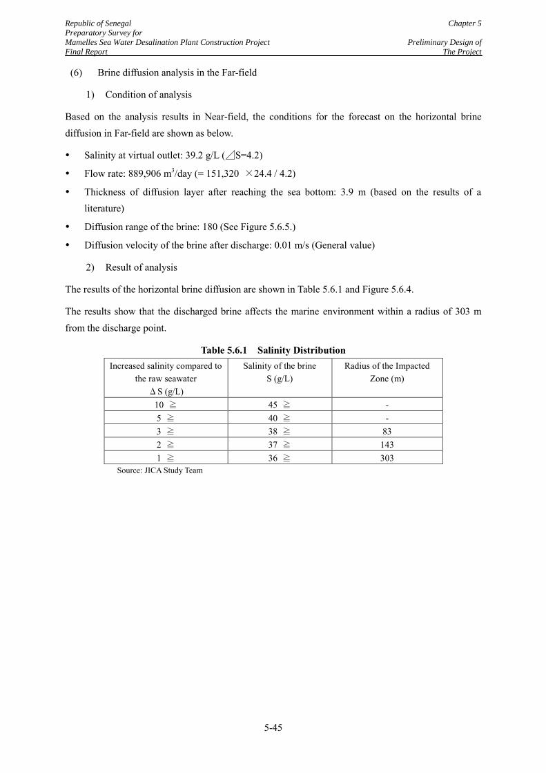
Republic of Senegal Chapter 5
Preparatory Survey for
Mamelles Sea Water Desalination Plant Construction Project Preliminary Design of
Final Report The Project
5-45
(6) Brine diffusion analysis in the Far-field
1) Condition of analysis
Based on the analysis results in Near-field, the conditions for the forecast on the horizontal brine diffusion in Far-field are shown as below.
Salinity at virtual outlet: 39.2 g/L (⊿S=4.2)
Flow rate: 889,906 m3/day (= 151,320 ×24.4 / 4.2)
Thickness of diffusion layer after reaching the sea bottom: 3.9 m (based on the results of a literature)
Diffusion range of the brine: 180 (See Figure 5.6.5.)
Diffusion velocity of the brine after discharge: 0.01 m/s (General value)
2) Result of analysis
The results of the horizontal brine diffusion are shown in Table 5.6.1 and Figure 5.6.4.
The results show that the discharged brine affects the marine environment within a radius of 303 m from the discharge point.
Table 5.6.1 Salinity Distribution Increased salinity compared to
the raw seawater ΔS (g/L)
Salinity of the brine S (g/L)
Radius of the Impacted Zone (m)
10 ≧ 45 ≧ - 5 ≧ 40 ≧ - 3 ≧ 38 ≧ 83 2 ≧ 37 ≧ 143 1 ≧ 36 ≧ 303
Source: JICA Study Team
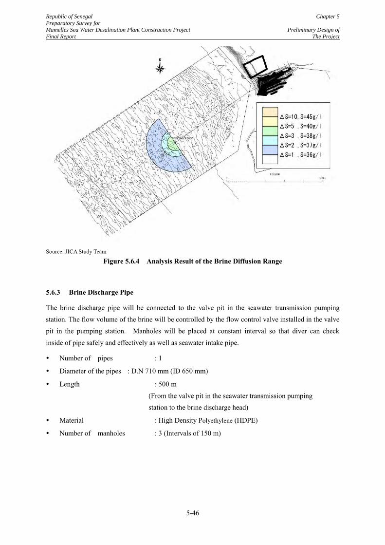
Republic of Senegal Chapter 5
Preparatory Survey for
Mamelles Sea Water Desalination Plant Construction Project Preliminary Design of
Final Report The Project
5-46
Source: JICA Study Team
Figure 5.6.4 Analysis Result of the Brine Diffusion Range
5.6.3 Brine Discharge Pipe
The brine discharge pipe will be connected to the valve pit in the seawater transmission pumping station. The flow volume of the brine will be controlled by the flow control valve installed in the valve pit in the pumping station. Manholes will be placed at constant interval so that diver can check inside of pipe safely and effectively as well as seawater intake pipe.
Number of pipes : 1
Diameter of the pipes : D.N 710 mm (ID 650 mm)
Length : 500 m (From the valve pit in the seawater transmission pumping station to the brine discharge head)
Material : High Density Polyethylene (HDPE)
Number of manholes : 3 (Intervals of 150 m)
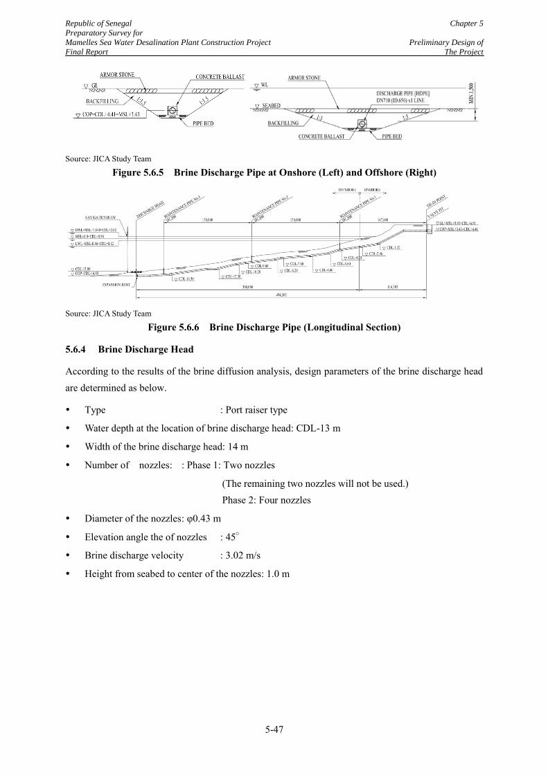
Republic of Senegal Chapter 5
Preparatory Survey for
Mamelles Sea Water Desalination Plant Construction Project Preliminary Design of
Final Report The Project
5-47
Source: JICA Study Team
Figure 5.6.5 Brine Discharge Pipe at Onshore (Left) and Offshore (Right)
Source: JICA Study Team
Figure 5.6.6 Brine Discharge Pipe (Longitudinal Section)
5.6.4 Brine Discharge Head
According to the results of the brine diffusion analysis, design parameters of the brine discharge head are determined as below.
Type : Port raiser type
Water depth at the location of brine discharge head: CDL-13 m
Width of the brine discharge head: 14 m
Number of nozzles: : Phase 1: Two nozzles
(The remaining two nozzles will not be used.) Phase 2: Four nozzles
Diameter of the nozzles : φ0.43 m
Elevation angle the of nozzles : 45°
Brine discharge velocity : 3.02 m/s
Height from seabed to center of the nozzles: 1.0 m
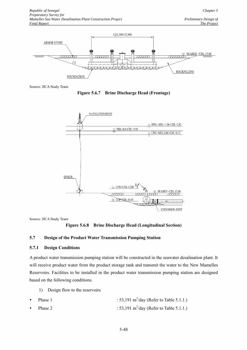
Republic of Senegal Chapter 5
Preparatory Survey for
Mamelles Sea Water Desalination Plant Construction Project Preliminary Design of
Final Report The Project
5-48
Source: JICA Study Team
Figure 5.6.7 Brine Discharge Head (Frontage)
Source: JICA Study Team
Figure 5.6.8 Brine Discharge Head (Longitudinal Section)
5.7 Design of the Product Water Transmission Pumping Station
5.7.1 Design Conditions
A product water transmission pumping station will be constructed in the seawater desalination plant. It will receive product water from the product storage tank and transmit the water to the New Mamelles Reservoirs. Facilities to be installed in the product water transmission pumping station are designed based on the following conditions.
1) Design flow to the reservoirs
Phase 1 : 53,191 m3/day (Refer to Table 5.1.1.)
Phase 2 : 53,191 m3/day (Refer to Table 5.1.1.)
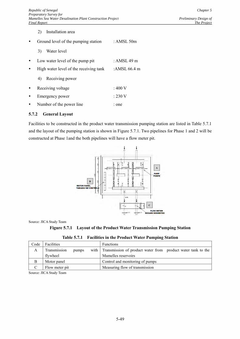
Republic of Senegal Chapter 5
Preparatory Survey for
Mamelles Sea Water Desalination Plant Construction Project Preliminary Design of
Final Report The Project
5-49
2) Installation area
Ground level of the pumping station : AMSL 50m
3) Water level
Low water level of the pump pit : AMSL 49 m
High water level of the receiving tank :AMSL 66.4 m
4) Receiving power
Receiving voltage : 400 V
Emergency power : 230 V
Number of the power line : one
5.7.2 General Layout
Facilities to be constructed in the product water transmission pumping station are listed in Table 5.7.1 and the layout of the pumping station is shown in Figure 5.7.1. Two pipelines for Phase 1 and 2 will be constructed at Phase 1and the both pipelines will have a flow meter pit.
Source: JICA Study Team
Figure 5.7.1 Layout of the Product Water Transmission Pumping Station
Table 5.7.1 Facilities in the Product Water Pumping Station Code Facilities Functions
A Transmission pumps with flywheel
Transmission of product water from product water tank to the Mamelles reservoirs
B Motor panel Control and monitoring of pumps C Flow meter pit Measuring flow of transmission
Source: JICA Study Team
construct at Phase 1 and the both pipelines will have a flow meter pit.
Figure 5.7.1 Layout of the Product Water Transmission Pumping Station
Table 5.7.1 Facilities in Product Water Pumping Station
A
B
C
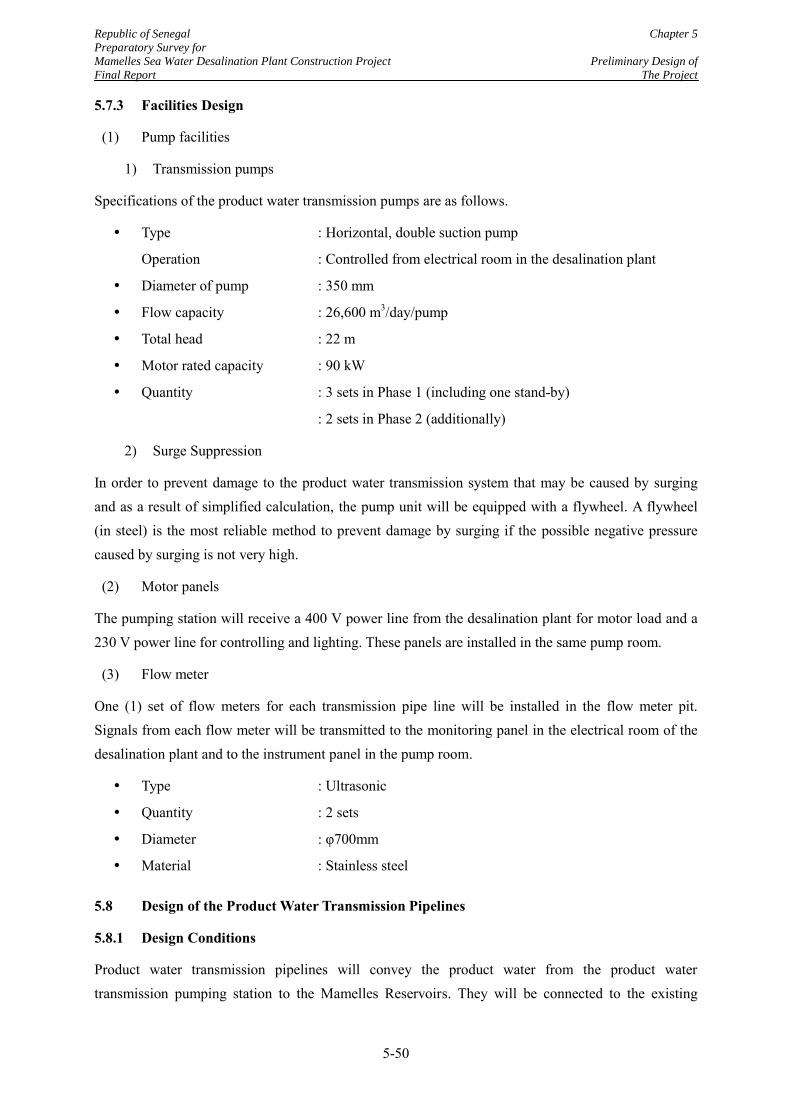
Republic of Senegal Chapter 5
Preparatory Survey for
Mamelles Sea Water Desalination Plant Construction Project Preliminary Design of
Final Report The Project
5-50
5.7.3 Facilities Design
(1) Pump facilities
1) Transmission pumps
Specifications of the product water transmission pumps are as follows.
Type : Horizontal, double suction pump
Operation : Controlled from electrical room in the desalination plant
Diameter of pump : 350 mm
Flow capacity : 26,600 m3/day/pump
Total head : 22 m
Motor rated capacity : 90 kW
Quantity : 3 sets in Phase 1 (including one stand-by)
: 2 sets in Phase 2 (additionally)
2) Surge Suppression
In order to prevent damage to the product water transmission system that may be caused by surging and as a result of simplified calculation, the pump unit will be equipped with a flywheel. A flywheel (in steel) is the most reliable method to prevent damage by surging if the possible negative pressure caused by surging is not very high.
(2) Motor panels
The pumping station will receive a 400 V power line from the desalination plant for motor load and a 230 V power line for controlling and lighting. These panels are installed in the same pump room.
(3) Flow meter
One (1) set of flow meters for each transmission pipe line will be installed in the flow meter pit. Signals from each flow meter will be transmitted to the monitoring panel in the electrical room of the desalination plant and to the instrument panel in the pump room.
Type : Ultrasonic
Quantity : 2 sets
Diameter : φ700mm
Material : Stainless steel
5.8 Design of the Product Water Transmission Pipelines
5.8.1 Design Conditions
Product water transmission pipelines will convey the product water from the product water transmission pumping station to the Mamelles Reservoirs. They will be connected to the existing
Republic of Senegal Chapter 5
Preparatory Survey for
Mamelles Sea Water Desalination Plant Construction Project Preliminary Design of
Final Report The Project
5-51
inflow pipes to the reservoirs on the premises of the Mamelles Reservoirs. Design conditions for the pipeline are shown in Table 5.8.1.
Table 5.8.1 Design Condition on Seawater Transmission Pipeline Item Condition Number of pipelines 2 lines Flow rate 0.616 m3/s for each line Water level at the product water transmission pumping station (=Low water level in the pump pit)
AMSL 49.00 m
Water level at the Mamelles Reservoir (=High water level of the existing Mamelles Reservoirs)
AMSL 66.40 m
Maximum water pressure (=Total pump head of the product water transmission pump)
0.22 MPa
Source: JICA Study Team
5.8.2 Pipe Design
(1) Plan and Profile
Plan and profile of the pipelines are shown in Figure 5.8.1. The pipeline originates from the product water supply tank in the desalination plant and ends at the connection points to the inflow pipes to the New Mamelles Reservoirs (3 reservoirs of 5,000, 10,000 and 15,000 m3 respectively).
The plan and profile was prepared based on the results of topographic survey and is presented in Appendix 5-1. The hydraulic head is also presented as well as the plan and profile.
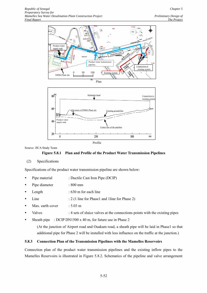
Republic of Senegal Chapter 5
Preparatory Survey for
Mamelles Sea Water Desalination Plant Construction Project Preliminary Design of
Final Report The Project
5-52
Source: JICA Study Team
Figure 5.8.1 Plan and Profile of the Product Water Transmission Pipelines
(2) Specifications
Specifications of the product water transmission pipeline are shown below:
Pipe material : Ductile Cast Iron Pipe (DCIP)
Pipe diameter : 800 mm
Length : 630 m for each line
Line : 2 (1 line for Phase1 and 1line for Phase 2)
Max. earth cover : 5.03 m
Valves : 4 sets of sluice valves at the connections points with the existing pipes
Sheath pipe : DCIP DN1500 x 40 m, for future use in Phase 2
(At the junction of Airport road and Ouakam road, a sheath pipe will be laid in Phase1 so that additional pipe for Phase 2 will be installed with less influence on the traffic at the junction.)
5.8.3 Connection Plan of the Transmission Pipelines with the Mamelles Reservoirs
Connection plan of the product water transmission pipelines and the existing inflow pipes to the Mamelles Reservoirs is illustrated in Figure 5.8.2. Schematics of the pipeline and valve arrangement
Plan
Flow
SWRO Plant site
Product water transmission pipeline
Product water supply tank
Connection to existing system
Existing system
Profile
Product water supply tank
Existing ground line
Center line of the pipeline
Elevation of SWRO Plant site
Hydraulic head Connection to existing system
0 50 100
m
Airport road
Ouakam road
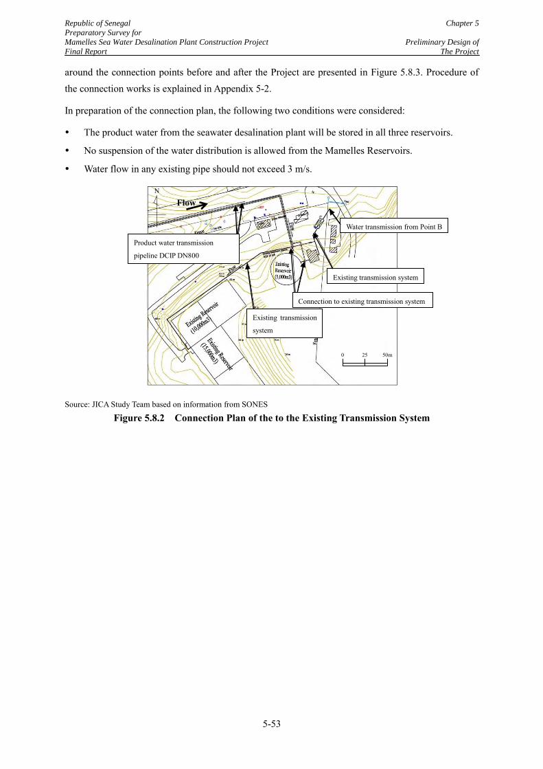
Republic of Senegal Chapter 5
Preparatory Survey for
Mamelles Sea Water Desalination Plant Construction Project Preliminary Design of
Final Report The Project
5-53
around the connection points before and after the Project are presented in Figure 5.8.3. Procedure of the connection works is explained in Appendix 5-2.
In preparation of the connection plan, the following two conditions were considered:
The product water from the seawater desalination plant will be stored in all three reservoirs.
No suspension of the water distribution is allowed from the Mamelles Reservoirs.
Water flow in any existing pipe should not exceed 3 m/s.
Source: JICA Study Team based on information from SONES
Figure 5.8.2 Connection Plan of the to the Existing Transmission System
Water transmission from Point B
Existing transmission system
Connection to existing transmission system
Existing transmission
system
Product water transmission
pipeline DCIP DN800
Flow N
0 25 50m
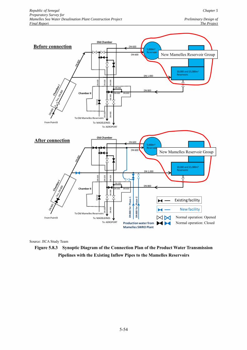
Republic of Senegal Chapter 5
Preparatory Survey for
Mamelles Sea Water Desalination Plant Construction Project Preliminary Design of
Final Report The Project
5-54
Source: JICA Study Team
Figure 5.8.3 Synoptic Diagram of the Connection Plan of the Product Water Transmission Pipelines with the Existing Inflow Pipes to the Mamelles Reservoirs
DN 800
From Point B
DN 600
DN
60
0
DN
60
0
DN
30
0
To Old Mamelles Reservoirs
Clo
sed
To MADELEINES
To AEROPORT
Chamber II
DN
60
0
DN
40
0D
N 3
00
DN 600
DN 300
Old Chamber
DN 600
DN 600
5,000m3
Reservoir
DN 1,000
10,000 and 15,000m3
Reservoirs
DN 600DN 600
From Point B
To Old Mamelles Reservoirs
Clo
sed
To MADELEINES
To AEROPORT
Chamber II
DN
60
0
DN
60
0
DN
30
0
DN
60
0
DN
40
0D
N 3
00
DN 300
Existing facility
Production water from Mamelles SWRO Plant
DN
800
fo
r P
has
e-1
DN
800
fo
r P
has
e-2
Old Chamber
DN 600
DN 600
5,000m3
Reservoir
DN 1,000
DN 800
10,000 and 15,000m3
Reservoirs
New facility
New Mamelles Reservoir Group
New Mamelles Reservoir Group
Before connection
After connection
Normal operation: Closed Normal operation: Opened
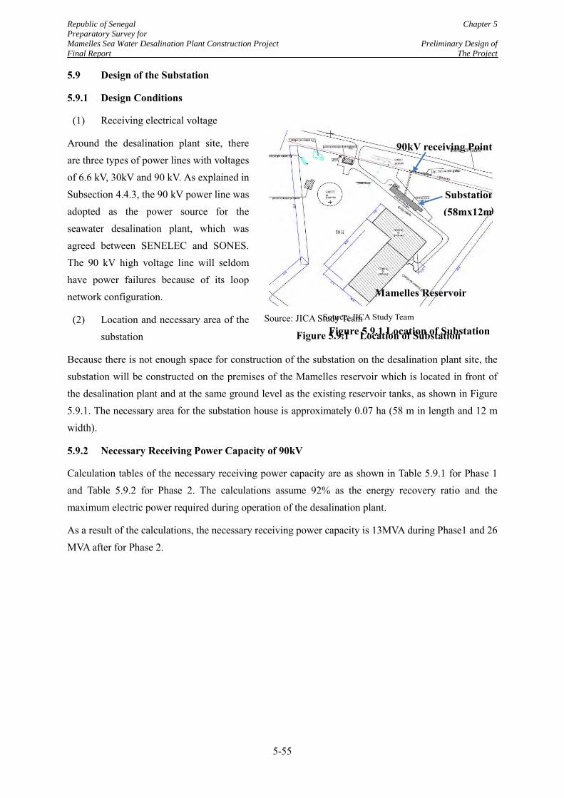
Republic of Senegal Chapter 5
Preparatory Survey for
Mamelles Sea Water Desalination Plant Construction Project Preliminary Design of
Final Report The Project
5-55
5.9 Design of the Substation
5.9.1 Design Conditions
(1) Receiving electrical voltage
Around the desalination plant site, there are three types of power lines with voltages of 6.6 kV, 30kV and 90 kV. As explained in Subsection 4.4.3, the 90 kV power line was adopted as the power source for the seawater desalination plant, which was agreed between SENELEC and SONES. The 90 kV high voltage line will seldom have power failures because of its loop network configuration.
(2) Location and necessary area of the substation
Because there is not enough space for construction of the substation on the desalination plant site, the substation will be constructed on the premises of the Mamelles reservoir which is located in front of the desalination plant and at the same ground level as the existing reservoir tanks, as shown in Figure 5.9.1. The necessary area for the substation house is approximately 0.07 ha (58 m in length and 12 m width).
5.9.2 Necessary Receiving Power Capacity of 90kV
Calculation tables of the necessary receiving power capacity are as shown in Table 5.9.1 for Phase 1 and Table 5.9.2 for Phase 2. The calculations assume 92% as the energy recovery ratio and the maximum electric power required during operation of the desalination plant.
As a result of the calculations, the necessary receiving power capacity is 13MVA during Phase1 and 26 MVA after for Phase 2.
Source: JICA Study Team
Figure 5.9.1 Location of Substation
5.1 Design of the Product Water Transmission Pipeline
5.2 Design of the Substation
5.2.1 Design Conditions
(1) Receiving electrical voltage
Around the desalination plant site, there are thrework configuration.
(2) Location and necessary area of the substation
Because there is not enough space for
construction of the substation in the desalination
plant site, the substation will be constructed
in the premise of Mamelles reservoir
which is located in front of the desalination plant and at the same ground level as the existing reservoir tanks as
shown in Figure 5.9.1. Necessary area for the substation house i
Substation (58mx12m)
Mamelles Reservoir
90kV receiving Point
Source: JICA Study Team
Figure 5.9.1 Location of Substation
)
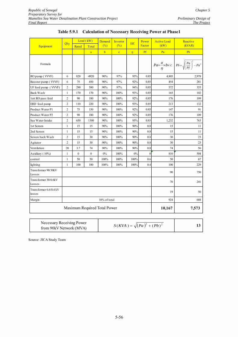
Republic of Senegal Chapter 5
Preparatory Survey for
Mamelles Sea Water Desalination Plant Construction Project Preliminary Design of
Final Report The Project
5-56
Table 5.9.1 Calculation of Necessary Receiving Power at Phase1
Source: JICA Study Team
Rated Total
a b c ŋ Pf Pa Pb
Formula
RO pump ( VVVF) 6 820 4920 90% 97% 95% 0.85 4,805 2,978
Booster pump ( VVVF) 6 75 450 90% 97% 92% 0.85 454 281
UF feed pump ( VVVF) 2 290 580 90% 97% 94% 0.85 572 355
Back Wash 1 170 170 90% 100% 93% 0.85 165 102
1srt RO pass feed 2 90 180 90% 100% 92% 0.85 176 109
ERD feed pump 2 110 220 90% 100% 93% 0.85 213 132
Product Water P1 2 75 150 90% 100% 92% 0.85 147 91
Product Water P2 2 90 180 90% 100% 92% 0.85 176 109
Sea Water Intake 2 650 1300 90% 100% 95% 0.85 1,232 763
1st Screen 1 15 15 90% 100% 90% 0.8 15 11
2nd Screen 1 15 15 90% 100% 90% 0.8 15 11
Screen back Wash 2 15 30 90% 100% 90% 0.8 30 23
Agitator 2 15 30 90% 100% 90% 0.8 30 23
Ventilation 20 3.7 74 90% 100% 90% 0.8 74 56
Auxiliary ( 10%) 1 0 0 0% 100% 0% 0 810 504
control 1 50 50 100% 100% 100% 0.6 50 67
lighting 1 100 100 100% 100% 100% 0.4 100 229
Transformer 90/30kV Losses
90 750
Transformer 30/6.6kV Losses
70 241
Transformer 6.6/0.4 kV losses 19 50
Margin 924 688
10,167 7,573
13
Reactive (kVAR)Equipment
Inverter(%)Q'ty
Necessary Receiving Power from 90kV Network (MVA)
Load ( kW) Demand(%) Eff.
Power Factor
Active Load (kW)
10% of total
Maximum Required Total Power
22
PaPf
PaPb
22 )()( PbPaKVAS
c ba
Pa
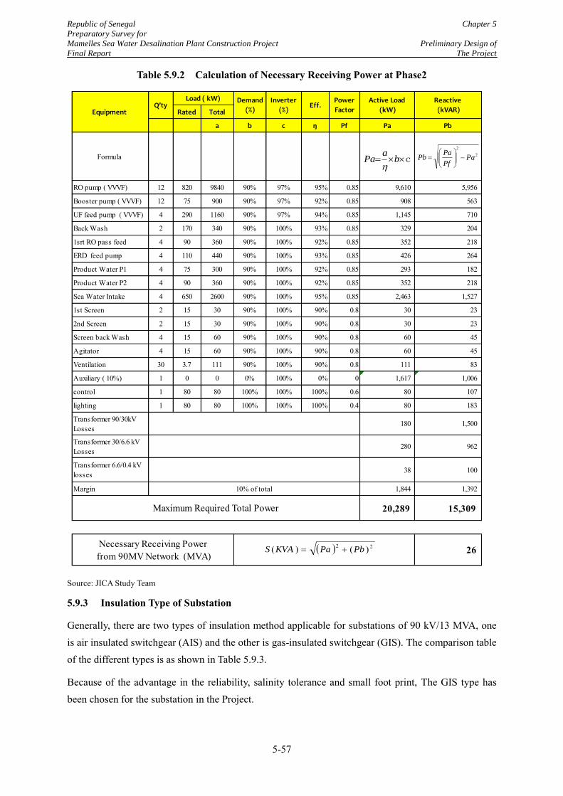
Republic of Senegal Chapter 5
Preparatory Survey for
Mamelles Sea Water Desalination Plant Construction Project Preliminary Design of
Final Report The Project
5-57
Table 5.9.2 Calculation of Necessary Receiving Power at Phase2
Source: JICA Study Team
5.9.3 Insulation Type of Substation
Generally, there are two types of insulation method applicable for substations of 90 kV/13 MVA, one is air insulated switchgear (AIS) and the other is gas-insulated switchgear (GIS). The comparison table of the different types is as shown in Table 5.9.3.
Because of the advantage in the reliability, salinity tolerance and small foot print, The GIS type has been chosen for the substation in the Project.
Rated Total
a b c ŋ Pf Pa Pb
Formula
RO pump ( VVVF) 12 820 9840 90% 97% 95% 0.85 9,610 5,956
Booster pump ( VVVF) 12 75 900 90% 97% 92% 0.85 908 563
UF feed pump ( VVVF) 4 290 1160 90% 97% 94% 0.85 1,145 710
Back Wash 2 170 340 90% 100% 93% 0.85 329 204
1srt RO pass feed 4 90 360 90% 100% 92% 0.85 352 218
ERD feed pump 4 110 440 90% 100% 93% 0.85 426 264
Product Water P1 4 75 300 90% 100% 92% 0.85 293 182
Product Water P2 4 90 360 90% 100% 92% 0.85 352 218
Sea Water Intake 4 650 2600 90% 100% 95% 0.85 2,463 1,527
1st Screen 2 15 30 90% 100% 90% 0.8 30 23
2nd Screen 2 15 30 90% 100% 90% 0.8 30 23
Screen back Wash 4 15 60 90% 100% 90% 0.8 60 45
Agitator 4 15 60 90% 100% 90% 0.8 60 45
Ventilation 30 3.7 111 90% 100% 90% 0.8 111 83
Auxiliary ( 10%) 1 0 0 0% 100% 0% 0 1,617 1,006
control 1 80 80 100% 100% 100% 0.6 80 107
lighting 1 80 80 100% 100% 100% 0.4 80 183
Transformer 90/30kV Losses
180 1,500
Transformer 30/6.6 kV Losses
280 962
Transformer 6.6/0.4 kV losses 38 100
Margin 1,844 1,392
20,289 15,309
26 Necessary Receiving Power from 90MV Network (MVA)
Active Load
(kW)
Reactive
(kVAR)
10% of total
Maximum Required Total Power
Eff.Power
Factor Q'ty
Load ( kW) Demand
(%)
Inverter
(%)Equipment
c ba
Pa
22
PaPf
PaPb
22 )()( PbPaKVAS
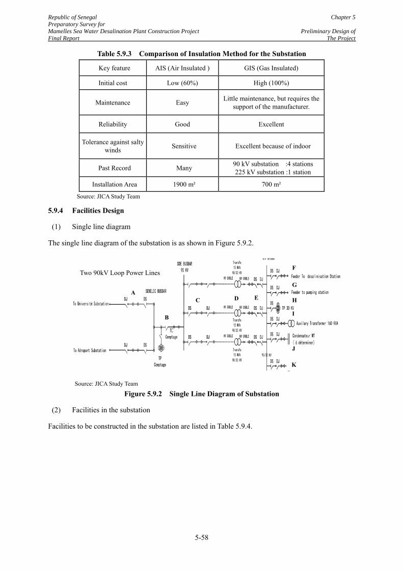
Republic of Senegal Chapter 5
Preparatory Survey for
Mamelles Sea Water Desalination Plant Construction Project Preliminary Design of
Final Report The Project
5-58
Table 5.9.3 Comparison of Insulation Method for the Substation
Key feature AIS (Air Insulated ) GIS (Gas Insulated)
Initial cost Low (60%) High (100%)
Maintenance Easy Little maintenance, but requires the support of the manufacturer.
Reliability Good Excellent
Tolerance against salty winds Sensitive Excellent because of indoor
Past Record Many 90 kV substation :4 stations 225 kV substation :1 station
Installation Area 1900 m² 700 m²
Source: JICA Study Team
5.9.4 Facilities Design
(1) Single line diagram
The single line diagram of the substation is as shown in Figure 5.9.2.
Source: JICA Study Team
Figure 5.9.2 Single Line Diagram of Substation
(2) Facilities in the substation
Facilities to be constructed in the substation are listed in Table 5.9.4.
C D E
F
G A
B
K
J
I
H
Figure5.9.5 Single Line Diagram
90kV Loop Existing Power Line
①
①
Two 90kV Loop Power Lines
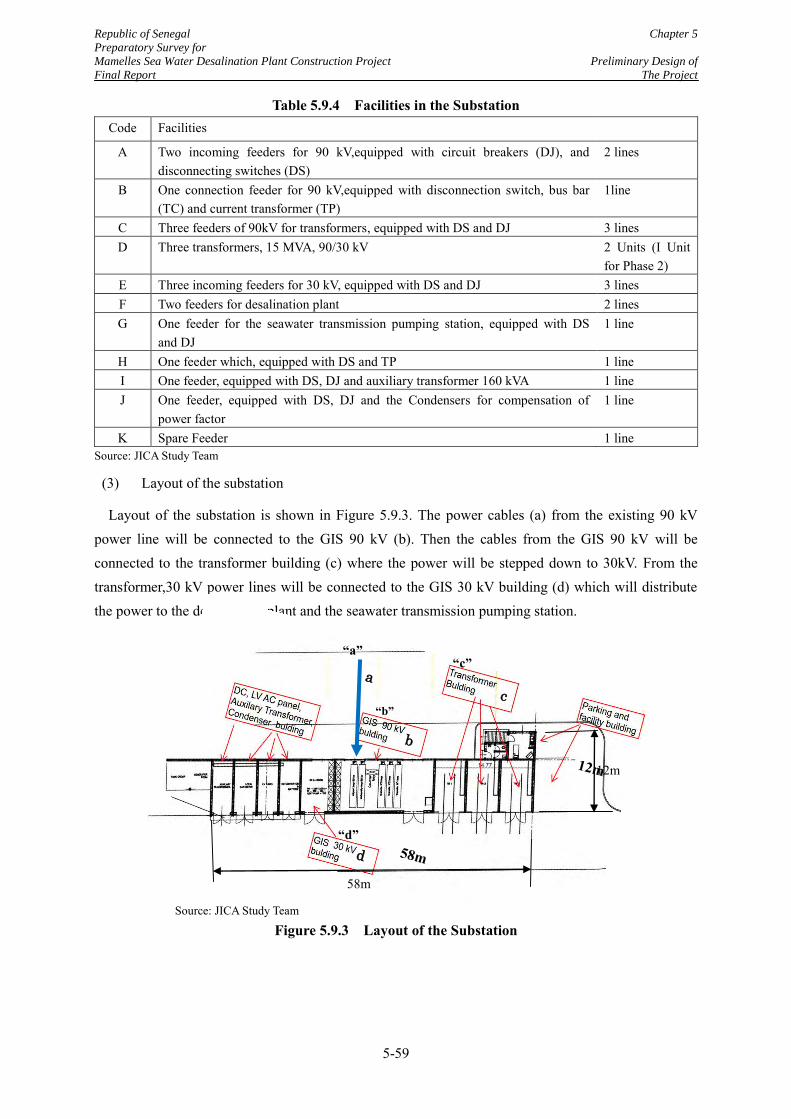
Republic of Senegal Chapter 5
Preparatory Survey for
Mamelles Sea Water Desalination Plant Construction Project Preliminary Design of
Final Report The Project
5-59
Table 5.9.4 Facilities in the Substation Code Facilities
A Two incoming feeders for 90 kV,equipped with circuit breakers (DJ), and disconnecting switches (DS)
2 lines
B One connection feeder for 90 kV,equipped with disconnection switch, bus bar (TC) and current transformer (TP)
1line
C Three feeders of 90kV for transformers, equipped with DS and DJ 3 lines D Three transformers, 15 MVA, 90/30 kV 2 Units (I Unit
for Phase 2) E Three incoming feeders for 30 kV, equipped with DS and DJ 3 lines F Two feeders for desalination plant 2 lines G One feeder for the seawater transmission pumping station, equipped with DS
and DJ 1 line
H One feeder which, equipped with DS and TP 1 line I One feeder, equipped with DS, DJ and auxiliary transformer 160 kVA 1 line J One feeder, equipped with DS, DJ and the Condensers for compensation of
power factor 1 line
K Spare Feeder 1 line Source: JICA Study Team
(3) Layout of the substation
Layout of the substation is shown in Figure 5.9.3. The power cables (a) from the existing 90 kV power line will be connected to the GIS 90 kV (b). Then the cables from the GIS 90 kV will be connected to the transformer building (c) where the power will be stepped down to 30kV. From the transformer,30 kV power lines will be connected to the GIS 30 kV building (d) which will distribute the power to the desalination plant and the seawater transmission pumping station.
Source: JICA Study Team
Figure 5.9.3 Layout of the Substation
12m
58m
a
b
c
d
“d”
“b”
“c” “a”
12m
58m
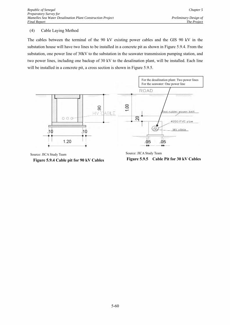
Republic of Senegal Chapter 5
Preparatory Survey for
Mamelles Sea Water Desalination Plant Construction Project Preliminary Design of
Final Report The Project
5-60
(4) Cable Laying Method
The cables between the terminal of the 90 kV existing power cables and the GIS 90 kV in the substation house will have two lines to be installed in a concrete pit as shown in Figure 5.9.4. From the substation, one power line of 30kV to the substation in the seawater transmission pumping station, and two power lines, including one backup of 30 kV to the desalination plant, will be installed. Each line will be installed in a concrete pit, a cross section is shown in Figure 5.9.5.
For the desalination plant: Two power lines For the seawater: One power line
Source: JICA Study Team
Figure 5.9.5 Cable Pit for 30 kV Cables Source: JICA Study Team
Figure 5.9.4 Cable pit for 90 kV Cables
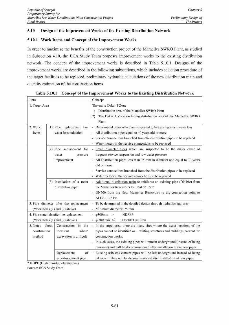
Republic of Senegal Chapter 5
Preparatory Survey for
Mamelles Sea Water Desalination Plant Construction Project Preliminary Design of
Final Report The Project
5-61
5.10 Design of the Improvement Works of the Existing Distribution Network
5.10.1 Work Items and Concept of the Improvement Works
In order to maximize the benefits of the construction project of the Mamelles SWRO Plant, as studied in Subsection 4.10, the JICA Study Team proposes improvement works to the existing distribution network. The concept of the improvement works is described in Table 5.10.1. Designs of the improvement works are described in the following subsections, which includes selection procedure of the target facilities to be replaced, preliminary hydraulic calculations of the new distribution main and quantity estimation of the construction items.
Table 5.10.1 Concept of the Improvement Works to the Existing Distribution Network Item Concept 1. Target Area The entire Dakar 1 Zone
1) Distribution area of the Mamelles SWRO Plant 2) The Dakar 1 Zone excluding distribution area of the Mamelles SWRO
Plant 2. Work
Items (1) Pipe replacement For
water loss reduction - Deteriorated pipes which are suspected to be causing much water loss - All distribution pipes equal to 40 years old or more - Service connections branched from the distribution pipes to be replaced - Water meters in the service connections to be replaced
(2) Pipe replacement for water pressure improvement
- Small diameter pipes which are suspected to be the major cause of frequent service suspension and low water pressure
- All Distribution pipes less than 75 mm in diameter and equal to 30 years old or more
- Service connections branched from the distribution pipes to be replaced - Water meters in the service connections to be replaced
(3) Installation of a main distribution pipe
- Additional distribution main to reinforce an existing pipe (DN400) from the Mamelles Reservoirs to Front de Terre
- DN700 from the New Mamelles Reservoirs to the connection point to ALG2, 13.5 km
3. Pipe diameter after the replacement (Work items (1) and (2) above)
- To be determined in the detailed design through hydraulic analyses - Minimum diameter: 75 mm
4. Pipe materials after the replacement (Work items (1) and (2) above.)
- φ300mm > ; HDPE* - φ 300 mm ≦ ; Ductile Cast Iron
5. Notes about constructionmethod
Construction in the locations where excavation is difficult
- In the target area, there are many sites where the exact locations of the pipes cannot be identified or existing structures and buildings prevent the construction works.
- In such cases, the existing pipes will remain underground (instead of being removed) and will be decommissioned after installation of the new pipes.
Replacement of asbestos cement pipe
- Existing asbestos cement pipes will be left underground instead of being taken out. They will be decommissioned after installation of new pipes.
* HDPE (High density polyethylene) Source: JICA Study Team
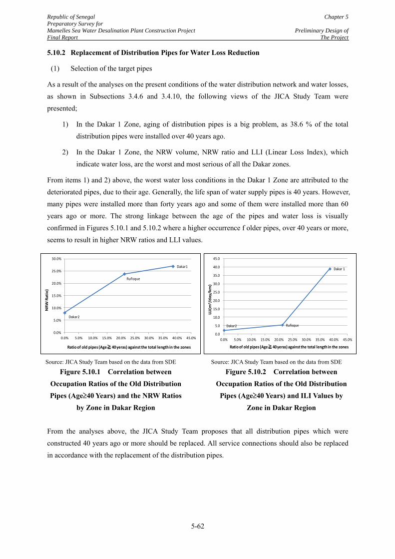
Republic of Senegal Chapter 5
Preparatory Survey for
Mamelles Sea Water Desalination Plant Construction Project Preliminary Design of
Final Report The Project
5-62
5.10.2 Replacement of Distribution Pipes for Water Loss Reduction
(1) Selection of the target pipes
As a result of the analyses on the present conditions of the water distribution network and water losses, as shown in Subsections 3.4.6 and 3.4.10, the following views of the JICA Study Team were presented;
1) In the Dakar 1 Zone, aging of distribution pipes is a big problem, as 38.6 % of the total distribution pipes were installed over 40 years ago.
2) In the Dakar 1 Zone, the NRW volume, NRW ratio and LLI (Linear Loss Index), which indicate water loss, are the worst and most serious of all the Dakar zones.
From items 1) and 2) above, the worst water loss conditions in the Dakar 1 Zone are attributed to the deteriorated pipes, due to their age. Generally, the life span of water supply pipes is 40 years. However, many pipes were installed more than forty years ago and some of them were installed more than 60 years ago or more. The strong linkage between the age of the pipes and water loss is visually confirmed in Figures 5.10.1 and 5.10.2 where a higher occurrence f older pipes, over 40 years or more, seems to result in higher NRW ratios and LLI values.
From the analyses above, the JICA Study Team proposes that all distribution pipes which were constructed 40 years ago or more should be replaced. All service connections should also be replaced in accordance with the replacement of the distribution pipes.
Source: JICA Study Team based on the data from SDE
Figure 5.10.1 Correlation between Occupation Ratios of the Old Distribution Pipes (Age≥40 Years) and the NRW Ratios
by Zone in Dakar Region
Source: JICA Study Team based on the data from SDE
Figure 5.10.2 Correlation between Occupation Ratios of the Old Distribution
Pipes (Age≥40 Years) and ILI Values by Zone in Dakar Region
Dakar2
Rufisque
Dakar1
0.0%
5.0%
10.0%
15.0%
20.0%
25.0%
30.0%
0.0% 5.0% 10.0% 15.0% 20.0% 25.0% 30.0% 35.0% 40.0% 45.0%
Ratio of old pipes (Age≧40 yeras) against the total length in the zones
NR
W R
ati
o)
Dakar2 Rufisque
Dakar 1
0.0
5.0
10.0
15.0
20.0
25.0
30.0
35.0
40.0
45.0
0.0% 5.0% 10.0% 15.0% 20.0% 25.0% 30.0% 35.0% 40.0% 45.0%
Ratio of old pipes (Age≧40 yeras) against the total length in the zones
LLI(
m3/d
ay
/km
)
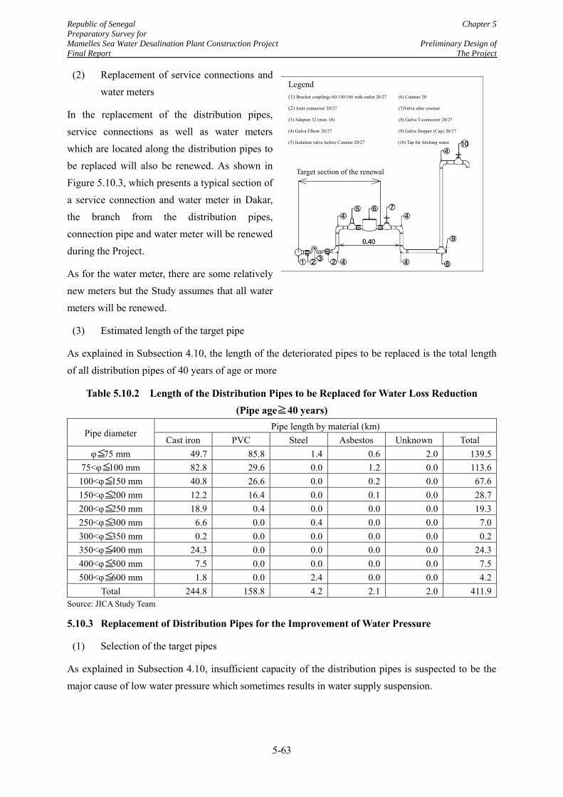
Republic of Senegal Chapter 5
Preparatory Survey for
Mamelles Sea Water Desalination Plant Construction Project Preliminary Design of
Final Report The Project
5-63
(2) Replacement of service connections and water meters
In the replacement of the distribution pipes, service connections as well as water meters which are located along the distribution pipes to be replaced will also be renewed. As shown in Figure 5.10.3, which presents a typical section of a service connection and water meter in Dakar, the branch from the distribution pipes, connection pipe and water meter will be renewed during the Project.
As for the water meter, there are some relatively new meters but the Study assumes that all water meters will be renewed.
(3) Estimated length of the target pipe
As explained in Subsection 4.10, the length of the deteriorated pipes to be replaced is the total length of all distribution pipes of 40 years of age or more
Table 5.10.2 Length of the Distribution Pipes to be Replaced for Water Loss Reduction (Pipe age≧40 years)
Pipe diameter Pipe length by material (km)
Cast iron PVC Steel Asbestos Unknown Total φ≦75 mm 49.7 85.8 1.4 0.6 2.0 139.5
75<φ≦100 mm 82.8 29.6 0.0 1.2 0.0 113.6 100<φ≦150 mm 40.8 26.6 0.0 0.2 0.0 67.6 150<φ≦200 mm 12.2 16.4 0.0 0.1 0.0 28.7 200<φ≦250 mm 18.9 0.4 0.0 0.0 0.0 19.3 250<φ≦300 mm 6.6 0.0 0.4 0.0 0.0 7.0 300<φ≦350 mm 0.2 0.0 0.0 0.0 0.0 0.2 350<φ≦400 mm 24.3 0.0 0.0 0.0 0.0 24.3 400<φ≦500 mm 7.5 0.0 0.0 0.0 0.0 7.5 500<φ≦600 mm 1.8 0.0 2.4 0.0 0.0 4.2
Total 244.8 158.8 4.2 2.1 2.0 411.9 Source: JICA Study Team
5.10.3 Replacement of Distribution Pipes for the Improvement of Water Pressure
(1) Selection of the target pipes
As explained in Subsection 4.10, insufficient capacity of the distribution pipes is suspected to be the major cause of low water pressure which sometimes results in water supply suspension.
Source: JICA Study Team
Figure 5.10.3 Typical Section of Service Connection for Renewal
From the analyses above, JICA Study Team proposes that all distribution pipes which were constructed 40 years ago or more be replaced. All service connections will also be replaced in according to the replacement of the distribution pipes.
(1) Replacement of service connection and water meter
In the replacement of the distribution pipes, service connections as well as water meters which are located in the distribution pipes to be replaced will also be renewed. As shown in Figure 5.10.3, which presents typical section of the service connection and water meter in Dakar, the branch from the distribution pipes, connection pipe and water meter will be renewed in the Project.
As for the water meter, there will be relatively new meters but the Study assumes all water meters to be renewed.
(2) Estimated length of the target pipe
As explained in Section 4.10, the length of the
deteriorated pipes to be replaced is estimated from that
in the entire Dakar 1 zone. As the distribution area of
Mamelles SWRO Plant occupies 50.1 % of the total area of Dakar 1 zone, the Study estimates that a half of the
all pipes with the age of 40 years or more will be the length of the target pipes of the replacement in the
distribution area of Mamelles SWRO Plant. Estimated length
Source: JICA Study Team
Figure 5.10.3 Typical Section of Service Connection for Renewal
Legend (1) Bracket couplings 60/110/160 with outlet 20/27 (6) Counter 20
(2) Joint connector 20/27 (7)Valve after counter
(3) Adaptor 32 (max 10) (8) Galva T-connector 20/27
(4) Galva Elbow 20/27 (9) Galva Stopper (Cap) 20/27
(5) Isolation valve before Counter 20/27 (10) Tap for fetching water
Target section of the renewal
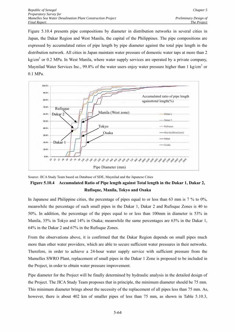
Republic of Senegal Chapter 5
Preparatory Survey for
Mamelles Sea Water Desalination Plant Construction Project Preliminary Design of
Final Report The Project
5-64
Figure 5.10.4 presents pipe compositions by diameter in distribution networks in several cities in Japan, the Dakar Region and West Manila, the capital of the Philippines. The pipe compositions are expressed by accumulated ratios of pipe length by pipe diameter against the total pipe length in the distribution network. All cities in Japan maintain water pressure of domestic water taps at more than 2 kg/cm2 or 0.2 MPa. In West Manila, where water supply services are operated by a private company, Maynilad Water Services Inc., 99.8% of the water users enjoy water pressure higher than 1 kg/cm2 or 0.1 MPa.
Source: JICA Study Team based on Database of SDE, Maynilad and the Japanese Cities
Figure 5.10.4 Accumulated Ratio of Pipe length against Total length in the Dakar 1, Dakar 2, Rufisque, Manila, Tokyo and Osaka
In Japanese and Philippine cities, the percentage of pipes equal to or less than 63 mm is 7 % to 0%, meanwhile the percentage of such small pipes in the Dakar 1, Dakar 2 and Rufisque Zones is 40 to 50%. In addition, the percentage of the pipes equal to or less than 100mm in diameter is 53% in Manila, 35% in Tokyo and 14% in Osaka; meanwhile the same percentages are 63% in the Dakar 1, 64% in the Dakar 2 and 67% in the Rufisque Zones.
From the observations above, it is confirmed that the Dakar Region depends on small pipes much more than other water providers, which are able to secure sufficient water pressures in their networks. Therefore, in order to achieve a 24-hour water supply service with sufficient pressure from the Mamelles SWRO Plant, replacement of small pipes in the Dakar 1 Zone is proposed to be included in the Project, in order to obtain water pressure improvement.
Pipe diameter for the Project will be finally determined by hydraulic analysis in the detailed design of the Project. The JICA Study Team proposes that in principle, the minimum diameter should be 75 mm. This minimum diameter brings about the necessity of the replacement of all pipes less than 75 mm. As, however, there is about 402 km of smaller pipes of less than 75 mm, as shown in Table 5.10.3,
Accumulated ratio of pipe length againsttotal length(%)
Pipe Diameter (mm)
Dakar 2 Rufisque
Dakar 1
Manila (West zone)
Tokyo
Osaka
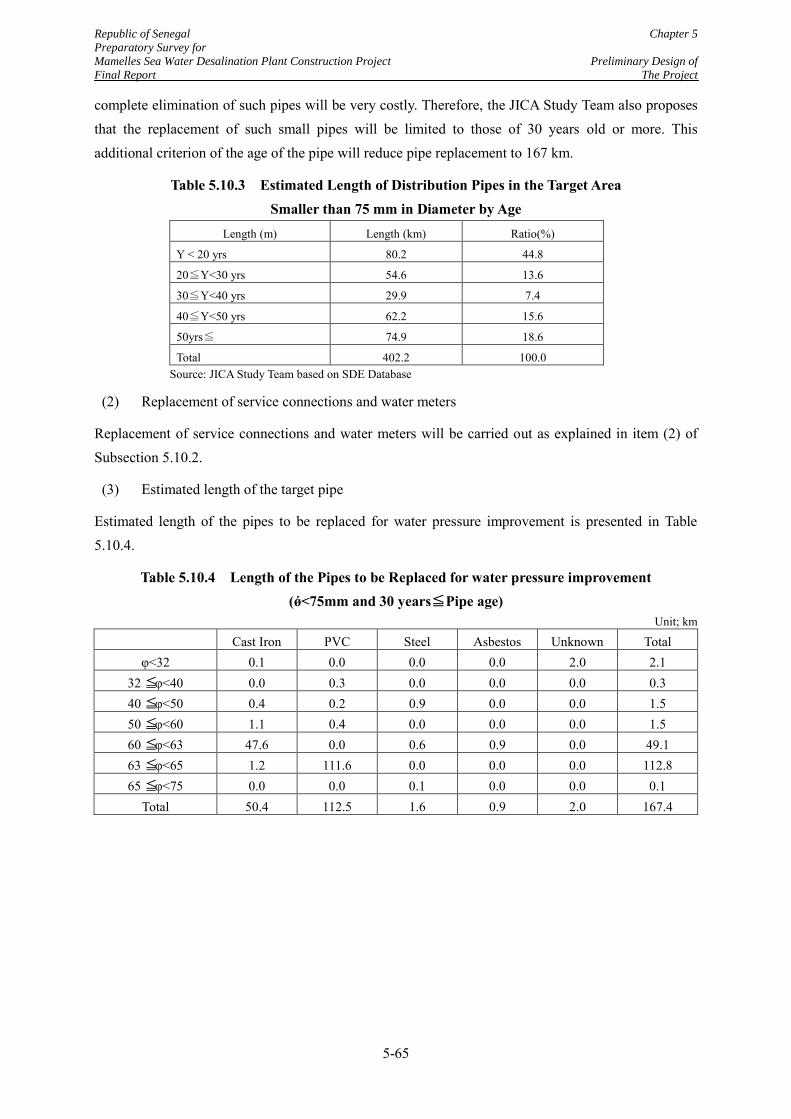
Republic of Senegal Chapter 5
Preparatory Survey for
Mamelles Sea Water Desalination Plant Construction Project Preliminary Design of
Final Report The Project
5-65
complete elimination of such pipes will be very costly. Therefore, the JICA Study Team also proposes that the replacement of such small pipes will be limited to those of 30 years old or more. This additional criterion of the age of the pipe will reduce pipe replacement to 167 km.
Table 5.10.3 Estimated Length of Distribution Pipes in the Target Area Smaller than 75 mm in Diameter by Age
Length (m) Length (km) Ratio(%)
Y < 20 yrs 80.2 44.8
20≦Y<30 yrs 54.6 13.6
30≦Y<40 yrs 29.9 7.4
40≦Y<50 yrs 62.2 15.6
50yrs≦ 74.9 18.6
Total 402.2 100.0 Source: JICA Study Team based on SDE Database
(2) Replacement of service connections and water meters
Replacement of service connections and water meters will be carried out as explained in item (2) of Subsection 5.10.2.
(3) Estimated length of the target pipe
Estimated length of the pipes to be replaced for water pressure improvement is presented in Table 5.10.4.
Table 5.10.4 Length of the Pipes to be Replaced for water pressure improvement (ǿ<75mm and 30 years≦Pipe age)
Unit; km
Cast Iron PVC Steel Asbestos Unknown Total
φ<32 0.1 0.0 0.0 0.0 2.0 2.1 32 ≦φ<40 0.0 0.3 0.0 0.0 0.0 0.3 40 ≦φ<50 0.4 0.2 0.9 0.0 0.0 1.5 50 ≦φ<60 1.1 0.4 0.0 0.0 0.0 1.5 60 ≦φ<63 47.6 0.0 0.6 0.9 0.0 49.1 63 ≦φ<65 1.2 111.6 0.0 0.0 0.0 112.8 65 ≦φ<75 0.0 0.0 0.1 0.0 0.0 0.1
Total 50.4 112.5 1.6 0.9 2.0 167.4
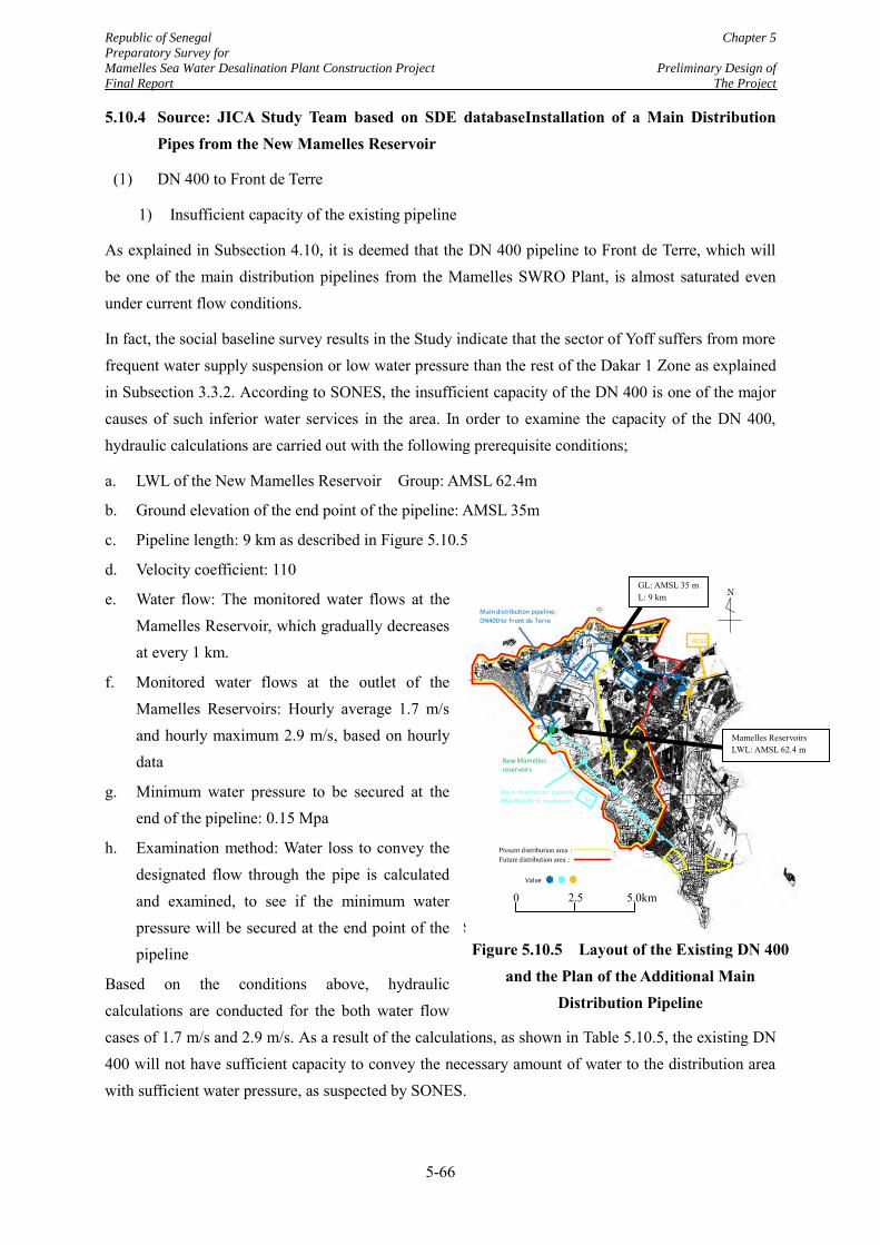
Republic of Senegal Chapter 5
Preparatory Survey for
Mamelles Sea Water Desalination Plant Construction Project Preliminary Design of
Final Report The Project
5-66
5.10.4 Source: JICA Study Team based on SDE databaseInstallation of a Main Distribution Pipes from the New Mamelles Reservoir
(1) DN 400 to Front de Terre
1) Insufficient capacity of the existing pipeline
As explained in Subsection 4.10, it is deemed that the DN 400 pipeline to Front de Terre, which will be one of the main distribution pipelines from the Mamelles SWRO Plant, is almost saturated even under current flow conditions.
In fact, the social baseline survey results in the Study indicate that the sector of Yoff suffers from more frequent water supply suspension or low water pressure than the rest of the Dakar 1 Zone as explained in Subsection 3.3.2. According to SONES, the insufficient capacity of the DN 400 is one of the major causes of such inferior water services in the area. In order to examine the capacity of the DN 400, hydraulic calculations are carried out with the following prerequisite conditions;
a. LWL of the New Mamelles Reservoir Group: AMSL 62.4m
b. Ground elevation of the end point of the pipeline: AMSL 35m
c. Pipeline length: 9 km as described in Figure 5.10.5
d. Velocity coefficient: 110
e. Water flow: The monitored water flows at the Mamelles Reservoir, which gradually decreases at every 1 km.
f. Monitored water flows at the outlet of the Mamelles Reservoirs: Hourly average 1.7 m/s and hourly maximum 2.9 m/s, based on hourly data
g. Minimum water pressure to be secured at the end of the pipeline: 0.15 Mpa
h. Examination method: Water loss to convey the designated flow through the pipe is calculated and examined, to see if the minimum water pressure will be secured at the end point of the pipeline
Based on the conditions above, hydraulic calculations are conducted for the both water flow cases of 1.7 m/s and 2.9 m/s. As a result of the calculations, as shown in Table 5.10.5, the existing DN 400 will not have sufficient capacity to convey the necessary amount of water to the distribution area with sufficient water pressure, as suspected by SONES.
Source: JICA Study Team
Figure 5.10.5 Layout of the Existing DN 400 and the Plan of the Additional Main
Distribution Pipeline
Main distribution pipeline; DN600/400 to madelines
Main distribution pipeline; DN400 to Front de Terre
New Mamelles
reservoirs
Valve
Present distribution area:Future distribution area:
ALG2
N
0 2.5 5.0km
GL: AMSL 35 m L: 9 km
Mamelles Reservoirs LWL: AMSL 62.4 m
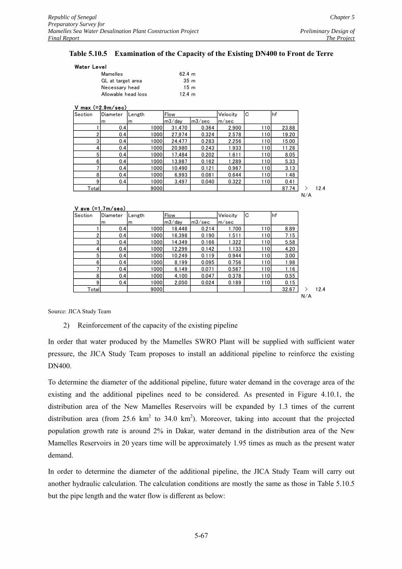
Republic of Senegal Chapter 5
Preparatory Survey for
Mamelles Sea Water Desalination Plant Construction Project Preliminary Design of
Final Report The Project
5-67
Table 5.10.5 Examination of the Capacity of the Existing DN400 to Front de Terre
Source: JICA Study Team
2) Reinforcement of the capacity of the existing pipeline
In order that water produced by the Mamelles SWRO Plant will be supplied with sufficient water pressure, the JICA Study Team proposes to install an additional pipeline to reinforce the existing DN400.
To determine the diameter of the additional pipeline, future water demand in the coverage area of the existing and the additional pipelines need to be considered. As presented in Figure 4.10.1, the distribution area of the New Mamelles Reservoirs will be expanded by 1.3 times of the current distribution area (from 25.6 km2 to 34.0 km2). Moreover, taking into account that the projected population growth rate is around 2% in Dakar, water demand in the distribution area of the New Mamelles Reservoirs in 20 years time will be approximately 1.95 times as much as the present water demand.
In order to determine the diameter of the additional pipeline, the JICA Study Team will carry out another hydraulic calculation. The calculation conditions are mostly the same as those in Table 5.10.5 but the pipe length and the water flow is different as below:
Water Level
Mamelles 62.4 mGL at target area 35 mNecessary head 15 mAllowable head loss 12.4 m
V max (=2.9m/sec)Section Diameter Length Flow Velocity C hf
m m m3/day m3/sec m/sec1 0.4 1000 31,470 0.364 2.900 110 23.882 0.4 1000 27,974 0.324 2.578 110 19.203 0.4 1000 24,477 0.283 2.256 110 15.004 0.4 1000 20,980 0.243 1.933 110 11.285 0.4 1000 17,484 0.202 1.611 110 8.056 0.4 1000 13,987 0.162 1.289 110 5.337 0.4 1000 10,490 0.121 0.967 110 3.138 0.4 1000 6,993 0.081 0.644 110 1.489 0.4 1000 3,497 0.040 0.322 110 0.41
Total 9000 87.74 > 12.4N/A
V ave (=1.7m/sec)Section Diameter Length Flow Velocity C hf
m m m3/day m3/sec m/sec1 0.4 1000 18,448 0.214 1.700 110 8.892 0.4 1000 16,398 0.190 1.511 110 7.153 0.4 1000 14,349 0.166 1.322 110 5.584 0.4 1000 12,299 0.142 1.133 110 4.205 0.4 1000 10,249 0.119 0.944 110 3.006 0.4 1000 8,199 0.095 0.756 110 1.987 0.4 1000 6,149 0.071 0.567 110 1.168 0.4 1000 4,100 0.047 0.378 110 0.559 0.4 1000 2,050 0.024 0.189 110 0.15
Total 9000 32.67 > 12.4N/A
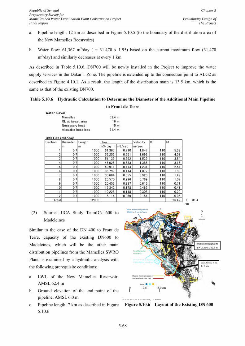
Republic of Senegal Chapter 5
Preparatory Survey for
Mamelles Sea Water Desalination Plant Construction Project Preliminary Design of
Final Report The Project
5-68
a. Pipeline length: 12 km as described in Figure 5.10.5 (to the boundary of the distribution area of the New Mamelles Reesrvoirs)
b. Water flow: 61,367 m3/day ( = 31,470 x 1.95) based on the current maximum flow (31,470 m3/day) and similarly decreases at every 1 km
As described in Table 5.10.6, DN700 will be newly installed in the Project to improve the water supply services in the Dakar 1 Zone. The pipeline is extended up to the connection point to ALG2 as described in Figure 4.10.1. As a result, the length of the distribution main is 13.5 km, which is the same as that of the existing DN700.
Table 5.10.6 Hydraulic Calculation to Determine the Diameter of the Additional Main Pipeline to Front de Terre
(2) Source: JICA Study TeamDN 600 to Madeleines
Similar to the case of the DN 400 to Front de Terre, capacity of the existing DN600 to Madeleines, which will be the other main distribution pipelines from the Mamelles SWRO Plant, is examined by a hydraulic analysis with the following prerequisite conditions;
a. LWL of the New Mamelles Reservoir: AMSL 62.4 m
b. Ground elevation of the end point of the pipeline: AMSL 6.0 m
c. Pipeline length: 7 km as described in Figure 5.10.6
Water Level
Mamelles 62.4 mGL at target area 16 mNecessary head 15 mAllowable head loss 31.4 m
Q=61,367m3/daySection Diameter Length Flow Velocity C hf
m m m3/day m3/sec m/sec1 0.7 1000 61,367 0.710 1.847 110 5.382 0.7 1000 56,253 0.651 1.693 110 4.583 0.7 1000 51,139 0.592 1.539 110 3.844 0.7 1000 46,025 0.533 1.385 110 3.165 0.7 1000 40,911 0.474 1.231 110 2.546 0.7 1000 35,797 0.414 1.077 110 1.997 0.7 1000 30,684 0.355 0.923 110 1.498 0.7 1000 25,570 0.296 0.769 110 1.079 0.7 1000 20,456 0.237 0.616 110 0.71
10 0.7 1000 15,342 0.178 0.462 110 0.4111 0.7 1000 10,228 0.118 0.308 110 0.2012 0.7 1000 5,114 0.059 0.154 110 0.05
Total 12000 25.42 < 31.4OK
Source: JICA Study Team
Figure 5.10.6 Layout of the Existing DN 600
Main distribution pipeline; DN600/400 to madelines
Main distribution pipeline; DN400 to Front de Terre
New Mamelles
reservoirs
Valve
Present distribution area:Future distribution area:
ALG2
N
0 2.5 5.0km
Mamelles Reservoirs LWL: AMSL 62.4 m
GL: AMSL 6 m L: 7 km
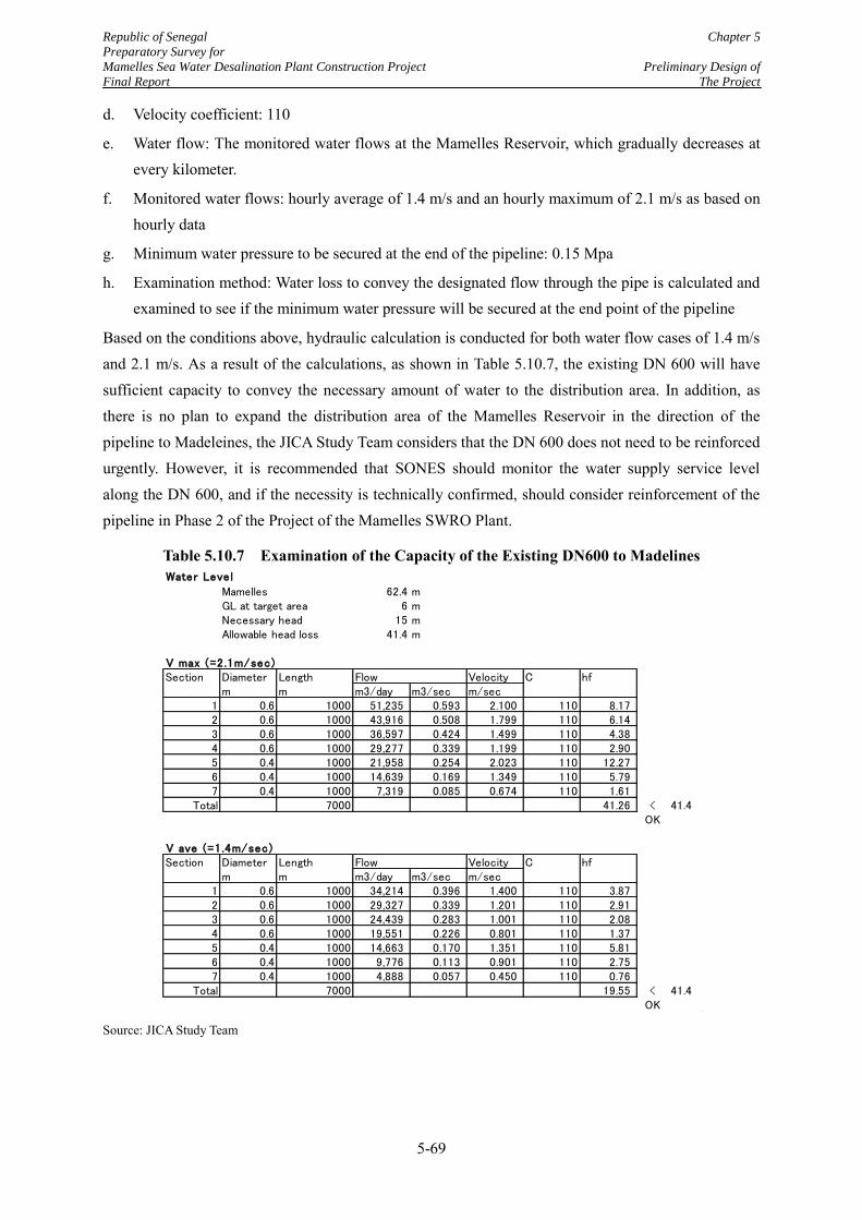
Republic of Senegal Chapter 5
Preparatory Survey for
Mamelles Sea Water Desalination Plant Construction Project Preliminary Design of
Final Report The Project
5-69
d. Velocity coefficient: 110
e. Water flow: The monitored water flows at the Mamelles Reservoir, which gradually decreases at every kilometer.
f. Monitored water flows: hourly average of 1.4 m/s and an hourly maximum of 2.1 m/s as based on hourly data
g. Minimum water pressure to be secured at the end of the pipeline: 0.15 Mpa
h. Examination method: Water loss to convey the designated flow through the pipe is calculated and examined to see if the minimum water pressure will be secured at the end point of the pipeline
Based on the conditions above, hydraulic calculation is conducted for both water flow cases of 1.4 m/s and 2.1 m/s. As a result of the calculations, as shown in Table 5.10.7, the existing DN 600 will have sufficient capacity to convey the necessary amount of water to the distribution area. In addition, as there is no plan to expand the distribution area of the Mamelles Reservoir in the direction of the pipeline to Madeleines, the JICA Study Team considers that the DN 600 does not need to be reinforced urgently. However, it is recommended that SONES should monitor the water supply service level along the DN 600, and if the necessity is technically confirmed, should consider reinforcement of the pipeline in Phase 2 of the Project of the Mamelles SWRO Plant.
Table 5.10.7 Examination of the Capacity of the Existing DN600 to Madelines
Source: JICA Study Team
Water Level
Mamelles 62.4 mGL at target area 6 mNecessary head 15 mAllowable head loss 41.4 m
V max (=2.1m/sec)Section Diameter Length Flow Velocity C hf
m m m3/day m3/sec m/sec1 0.6 1000 51,235 0.593 2.100 110 8.172 0.6 1000 43,916 0.508 1.799 110 6.143 0.6 1000 36,597 0.424 1.499 110 4.384 0.6 1000 29,277 0.339 1.199 110 2.905 0.4 1000 21,958 0.254 2.023 110 12.276 0.4 1000 14,639 0.169 1.349 110 5.797 0.4 1000 7,319 0.085 0.674 110 1.61
Total 7000 41.26 < 41.4OK
V ave (=1.4m/sec)Section Diameter Length Flow Velocity C hf
m m m3/day m3/sec m/sec1 0.6 1000 34,214 0.396 1.400 110 3.872 0.6 1000 29,327 0.339 1.201 110 2.913 0.6 1000 24,439 0.283 1.001 110 2.084 0.6 1000 19,551 0.226 0.801 110 1.375 0.4 1000 14,663 0.170 1.351 110 5.816 0.4 1000 9,776 0.113 0.901 110 2.757 0.4 1000 4,888 0.057 0.450 110 0.76
Total 7000 19.55 < 41.4OK
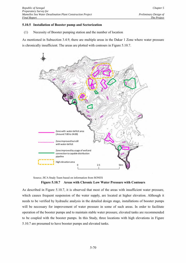
Republic of Senegal Chapter 5
Preparatory Survey for
Mamelles Sea Water Desalination Plant Construction Project Preliminary Design of
Final Report The Project
5-70
5.10.5 Installation of Booster pump and Sectorization
(1) Necessity of Booster pumping station and the number of location
As mentioned in Subsection 3.4.9, there are multiple areas in the Dakar 1 Zone where water pressure is chronically insufficient. The areas are plotted with contours in Figure 5.10.7.
Source; JICA Study Team based on information from SONES
Figure 5.10.7 Areas with Chronic Low Water Pressure with Contours
As described in Figure 5.10.7, it is observed that most of the areas with insufficient water pressure, which causes frequent suspension of the water supply, are located at higher elevation. Although it needs to be verified by hydraulic analysis in the detailed design stage, installations of booster pumps will be necessary for improvement of water pressure in some of such areas. In order to facilitate operation of the booster pumps and to maintain stable water pressure, elevated tanks are recommended to be coupled with the booster pumps. In this Study, three locations with high elevations in Figure 5.10.7 are presumed to have booster pumps and elevated tanks.
Zone with water deficit area(Around 7:00 to 24:00)
Zone improved but still with water deficit
Zone improved by usage of well and connection to capable distribution pipeline
High elevation area0 2.5 5km
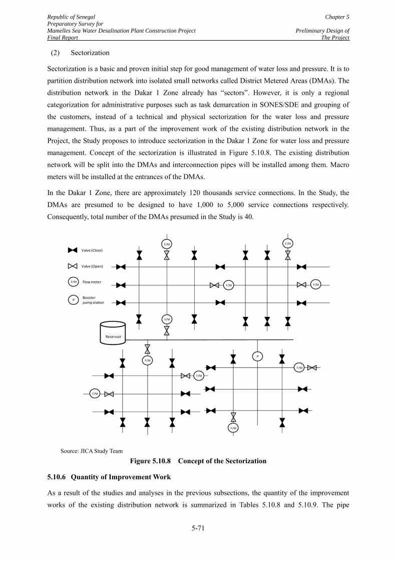
Republic of Senegal Chapter 5
Preparatory Survey for
Mamelles Sea Water Desalination Plant Construction Project Preliminary Design of
Final Report The Project
5-71
(2) Sectorization
Sectorization is a basic and proven initial step for good management of water loss and pressure. It is to partition distribution network into isolated small networks called District Metered Areas (DMAs). The distribution network in the Dakar 1 Zone already has “sectors”. However, it is only a regional categorization for administrative purposes such as task demarcation in SONES/SDE and grouping of the customers, instead of a technical and physical sectorization for the water loss and pressure management. Thus, as a part of the improvement work of the existing distribution network in the Project, the Study proposes to introduce sectorization in the Dakar 1 Zone for water loss and pressure management. Concept of the sectorization is illustrated in Figure 5.10.8. The existing distribution network will be split into the DMAs and interconnection pipes will be installed among them. Macro meters will be installed at the entrances of the DMAs.
In the Dakar 1 Zone, there are approximately 120 thousands service connections. In the Study, the DMAs are presumed to be designed to have 1,000 to 5,000 service connections respectively. Consequently, total number of the DMAs presumed in the Study is 40.
Source: JICA Study Team
Figure 5.10.8 Concept of the Sectorization
5.10.6 Quantity of Improvement Work
As a result of the studies and analyses in the previous subsections, the quantity of the improvement works of the existing distribution network is summarized in Tables 5.10.8 and 5.10.9. The pipe
F/M
Reservoir
F/M
F/M
P
F/M
Valve (Close)
F/M Flow meter
PBoosterpump station
Valve (Open)
F/M
F/M
F/M
F/M
F/M
F/M
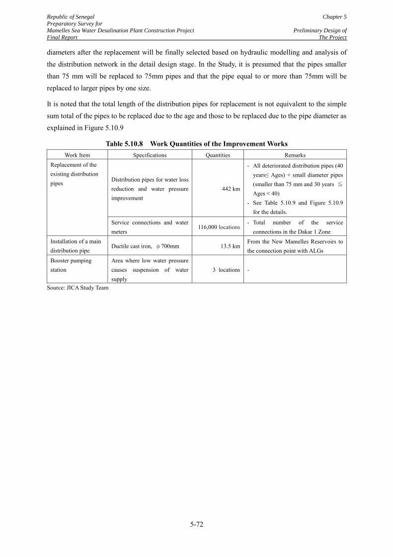
Republic of Senegal Chapter 5
Preparatory Survey for
Mamelles Sea Water Desalination Plant Construction Project Preliminary Design of
Final Report The Project
5-72
diameters after the replacement will be finally selected based on hydraulic modelling and analysis of the distribution network in the detail design stage. In the Study, it is presumed that the pipes smaller than 75 mm will be replaced to 75mm pipes and that the pipe equal to or more than 75mm will be replaced to larger pipes by one size.
It is noted that the total length of the distribution pipes for replacement is not equivalent to the simple sum total of the pipes to be replaced due to the age and those to be replaced due to the pipe diameter as explained in Figure 5.10.9
Table 5.10.8 Work Quantities of the Improvement Works Work Item Specifications Quantities Remarks
Replacement of the existing distribution pipes Distribution pipes for water loss
reduction and water pressure improvement
442 km
- All deteriorated distribution pipes (40 years≤ Ages) + small diameter pipes (smaller than 75 mm and 30 years ≦ Ages < 40)
- See Table 5.10.9 and Figure 5.10.9 for the details.
Service connections and water meters
116,000 locations - Total number of the service
connections in the Dakar 1 Zone Installation of a main distribution pipe
Ductile cast iron, φ700mm 13.5 km From the New Mamelles Reservoirs to the connection point with ALGs
Booster pumping station
Area where low water pressure causes suspension of water supply
3 locations -
Source: JICA Study Team
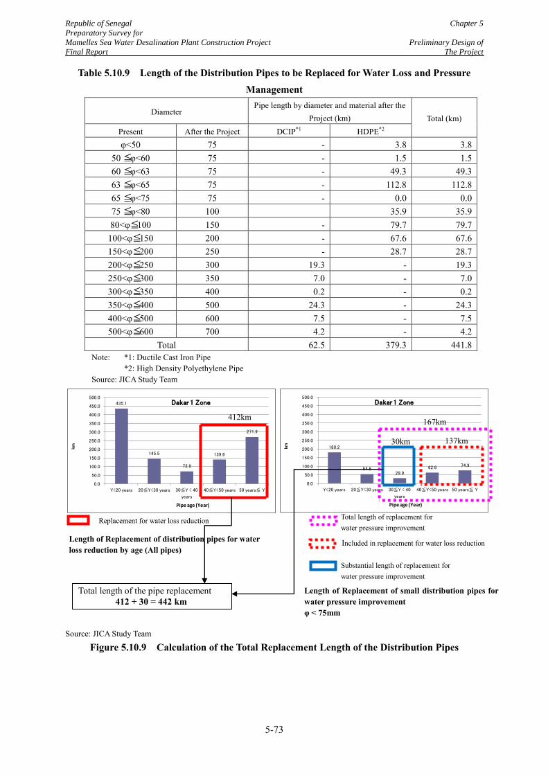
Republic of Senegal Chapter 5
Preparatory Survey for
Mamelles Sea Water Desalination Plant Construction Project Preliminary Design of
Final Report The Project
5-73
Table 5.10.9 Length of the Distribution Pipes to be Replaced for Water Loss and Pressure Management
Note: *1: Ductile Cast Iron Pipe *2: High Density Polyethylene Pipe Source: JICA Study Team
Source: JICA Study Team
Figure 5.10.9 Calculation of the Total Replacement Length of the Distribution Pipes
Diameter Pipe length by diameter and material after the
Project (km) Total (km) Present After the Project DCIP*1 HDPE*2 φ<50 75 - 3.8 3.8
50 ≦φ<60 75 - 1.5 1.5 60 ≦φ<63 75 - 49.3 49.3 63 ≦φ<65 75 - 112.8 112.8 65 ≦φ<75 75 - 0.0 0.0 75 ≦φ<80 100 35.9 35.9 80<φ≦100 150 - 79.7 79.7
100<φ≦150 200 - 67.6 67.6 150<φ≦200 250 - 28.7 28.7 200<φ≦250 300 19.3 - 19.3 250<φ≦300 350 7.0 - 7.0 300<φ≦350 400 0.2 - 0.2 350<φ≦400 500 24.3 - 24.3 400<φ≦500 600 7.5 - 7.5 500<φ≦600 700 4.2 - 4.2
Total 62.5 379.3 441.8
435.1
145.5
72.9
139.6
271.9
0.0
50.0
100.0
150.0
200.0
250.0
300.0
350.0
400.0
450.0
500.0
Y<20 years 20≦Y<30 years 30≦Y < 40
years
40≦Y<50 years 50 years≦ Y
km
Pipe age (Year)
Dakar 1 Zone
180.2
54.6 29.9
62.6 74.9
0.0
50.0
100.0
150.0
200.0
250.0
300.0
350.0
400.0
450.0
500.0
Y<20 years 20≦Y<30 years 30≦Y < 40
years
40≦Y<50 years 50 years≦ Y
km
Pipe age (Year)
Dakar 1 Zone
412km 167km
137km 30km
Length of Replacement of small distribution pipes for water pressure improvement φ < 75mm
Total length of replacement for water pressure improvement
Included in replacement for water loss reduction
Substantial length of replacement for water pressure improvement
Length of Replacement of distribution pipes for water loss reduction by age (All pipes)
Replacement for water loss reduction
Total length of the pipe replacement 412 + 30 = 442 km
Republic of Senegal Chapter 5
Preparatory Survey for
Mamelles Sea Water Desalination Plant Construction Project Preliminary Design of
Final Report The Project
5-74
5.10.7 Proposed Methodologies for the Final Determination of the Distribution Pipes to be replaced in the Detailed Design
(1) Conditions for the setting of the methodologies
In the detailed design of the Project, the exact identification of the target pipes to be replaced and determination of the pipe diameters will be conducted and the pipe diameters after the replacement works will be calculated. The method of the detailed design is planned in consideration of the following conditions:
An ongoing study, which is called as “Sectorization Study” being implemented by SDE and a local consultant, is trying to draw clear boundaries of the distribution areas of all water sources, such as the Mamelles Reservoir, Madeleines Reservoir, Point G Pumping Station, etc. The study results may present a different plan for the distribution area of the Mamelles Reservoir or the Mamelles SWRO Plant from that in the Study.
SDE has an inventory database of the distribution pipes which indicate the diameters, materials, length and year of construction. Separately, there is a distribution network map which indicates diameters, materials and length of the distribution pipes. However, the database and map do not have a link, because of which, the location of an old pipe to be replaced in the database cannot be identified in the map. The location information on the database is only the zone to which the pipe belongs.
When SDE carries out the intensive rehabilitation program of the distribution network, according to the interviews with SDE, firstly it will select the target area based on leakage detection investigation results and the number of the incidents in the distribution network. Then, if necessary, it will carry out additional leakage detection investigations in the target area and sometimes conduct excavations tests to visually check the materials and conditions of the pipes, so as to finally determine the pipes to be replaced.
(2) Proposed methodologies and necessary information from SONES and SDE
In the detailed design, replacement works of the existing distribution pipes will be carried out based on hydraulic analyses. The hydraulic analyses will simulate the capacity of the existing distribution network to identify the deficiencies in the distribution area of the Mamelles SWRO Plant. According to the deficiencies, the consultancy company will prepare an improvement plan of the distribution network and verify the plan by another hydraulic analysis.
In the design process above, the consultant will prepare the hydraulic models of the distribution network. In addition, it will prepare an improvement plan taking into account the prioritized pipes to be replaced for water loss reduction and water pressure improvement. To complete these tasks, the consultancy company will need important information from SONES and SDE as follows:
a. Distribution area of the Mamelles SWRO Plant ( Result of review on the aforesaid Sectorization Study)
Republic of Senegal Chapter 5
Preparatory Survey for
Mamelles Sea Water Desalination Plant Construction Project Preliminary Design of
Final Report The Project
5-75
b. Distribution network map which presents the latest network information to prepare a hydraulic model
c. Flow, water pressure, water consumption and water level data of the reservoirs to know flow conditions in the distribution network
d. List of prioritized pipes of the distribution pipes to be replaced, with the exact locations of the pipes and their diameters, ages and materials assumed.
(Because of the missing link between the inventory database and the distribution network map, the consultant will not be able to identify the deteriorated pipes alone. Thus, selection of target pipes for replacement shall be carried out by SONES /SDE. If it is difficult to identify the pipe age after installation of the pipe, SONES/SDE will estimate the age referring to development year of the area concerned, or provide all information that are necessary for identification of the target pipes.)
e. Basis of the above prioritization such as leakage detection investigation results, visual inspection results of the existing pipes by test excavation and record of incidents.
f. Development plan of the distribution network in the Dakar 1 Zone especially in the developing areas, as the developing area tend to suffer from the insufficient water pressure.
The proposed methodologies in the detailed design to finally determine the pipes to be replaced are given in Figure 5.10.10.
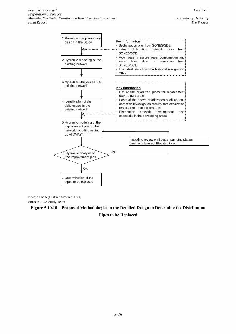
Republic of Senegal Chapter 5
Preparatory Survey for
Mamelles Sea Water Desalination Plant Construction Project Preliminary Design of
Final Report The Project
5-76
Note; *DMA (District Metered Area) Source: JICA Study Team
Figure 5.10.10 Proposed Methodologies in the Detailed Design to Determine the Distribution Pipes to be Replaced
1. Review of the preliminary
design in the Study
2. Hydraulic modeling of the
existing network
3. Hydraulic analysis of the
existing network
5 Hydraulic modeling of the
improvement plan of the
network including setting
up of DMAs*
Key information
Sectorization plan from SONES/SDE
Latest distribution network map from
SONES/SDE
Flow, water pressure water consumption and
water level data of reservoirs from
SONES/SDE
The latest map from the National Geographic
Office
Key information
List of the prioritized pipes for replacement
from SONES/SDE
Basis of the above prioritization such as leak
detection investigation results, test excavation
results, record of incidents, etc
Distribution network development plan
especially in the developing areas
4. Identification of the
deficiencies in the
existing network
7 Determination of the
pipes to be replaced
6. Hydraulic analysis of
the improvement plan
OK
NG
Including review on Booster pumping station
and installation of Elevated tank
Republic of Senegal Chapter 6
Preparatory Survey for
Mamelles Sea Water Desalination Plant Construction Project Environmental and Social
Final Report Considerations
6-1
CHAPTER 6 ENVIRONMENTAL AND SOCIAL CONSIDERATIONS
6.1 General Scope of the Project and Relevant Environmental and Social Situations
6.1.1 General Scope and Target Area of the Project
(1) Objective of the Project
The project is to construct the seawater desalination plant and the related facilities such as a sea water transmission pipeline and brine discharge pipeline in the Mamelles Area and to improve the existing water distribution network in order to mitigate the serious water shortage and the insufficient water pressure in the region.
(2) Main scope of the Project
1) Seawater desalination facilities
The proposed facilities of the seawater desalination facilities are as followed.
Seawater intake and brine discharge
Seawater transmission pumping station
Seawater transmission pipeline and brine discharge pipeline
Seawater desalination plant
Product water transmission pumping station
Product water transmission pipeline
Land development for the plant sites
2) Improvement of the existing distribution network
Installation of 13.5 km of the main distribution pipes from the Mamelles Reservoirs
Replacement of 442 km of the existing distribution pipes in the Dakar Zone 1
(3) Target Areas of the Project
Target areas of the Project are shown in Figure 6.1.1.
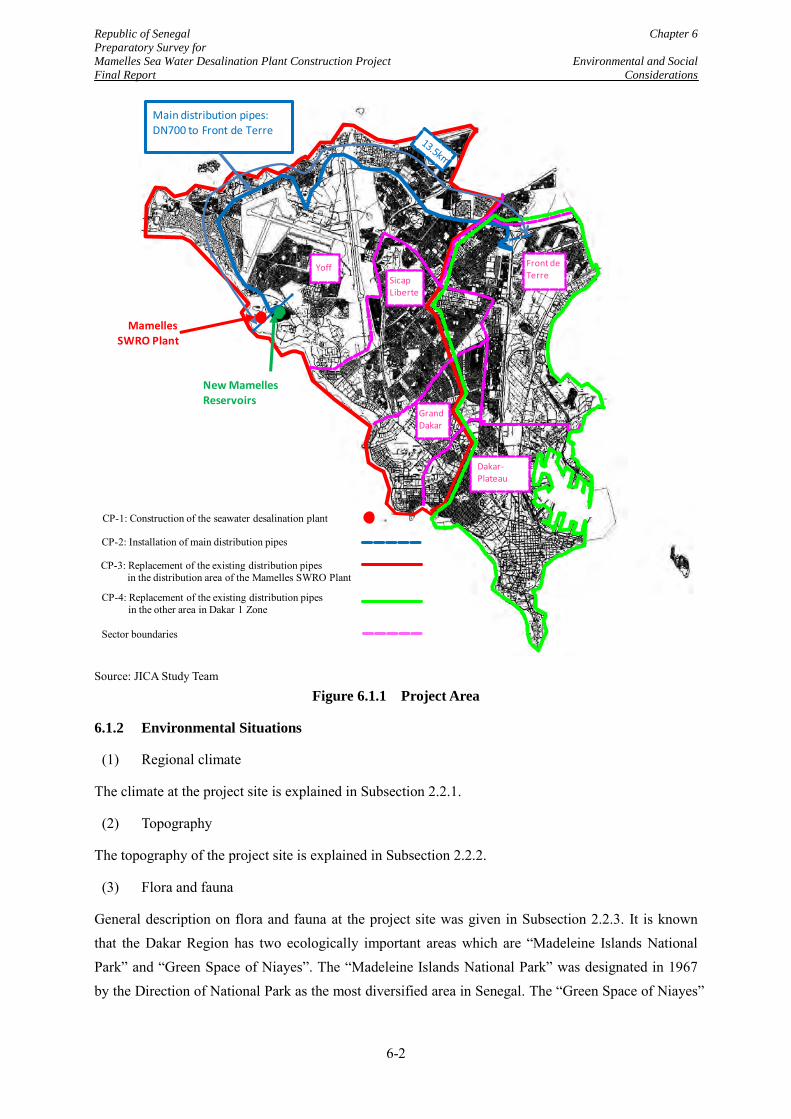
Republic of Senegal Chapter 6
Preparatory Survey for
Mamelles Sea Water Desalination Plant Construction Project Environmental and Social
Final Report Considerations
6-2
Source: JICA Study Team
Figure 6.1.1 Project Area
6.1.2 Environmental Situations
(1) Regional climate
The climate at the project site is explained in Subsection 2.2.1.
(2) Topography
The topography of the project site is explained in Subsection 2.2.2.
(3) Flora and fauna
General description on flora and fauna at the project site was given in Subsection 2.2.3. It is known that the Dakar Region has two ecologically important areas which are “Madeleine Islands National Park” and “Green Space of Niayes”. The “Madeleine Islands National Park” was designated in 1967 by the Direction of National Park as the most diversified area in Senegal. The “Green Space of Niayes”
Main distribution pipes: DN700 to Front de Terre
New Mamelles
Reservoirs
SicapLiberte
Front deTerre
Dakar-Plateau
Grand Dakar
Yoff
CP-3: Replacement of the existing distribution pipes in the distribution area of the Mamelles SWRO Plant
Sector boundaries
CP-2: Installation of main distribution pipes
CP-4: Replacement of the existing distribution pipes in the other area in Dakar 1 Zone
Mamelles
SWRO Plant
CP-1: Construction of the seawater desalination plant
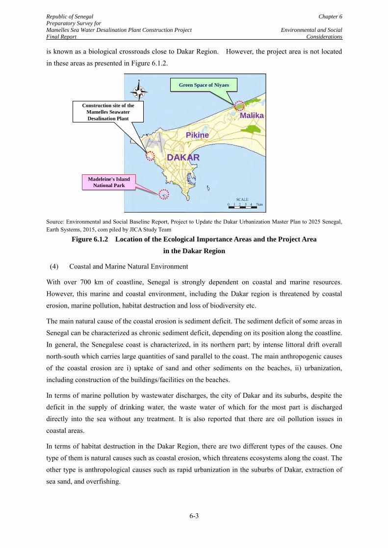
Republic of Senegal Chapter 6
Preparatory Survey for
Mamelles Sea Water Desalination Plant Construction Project Environmental and Social
Final Report Considerations
6-3
is known as a biological crossroads close to Dakar Region. However, the project area is not located in these areas as presented in Figure 6.1.2.
Source: Environmental and Social Baseline Report, Project to Update the Dakar Urbanization Master Plan to 2025 Senegal, Earth Systems, 2015, com piled by JICA Study Team
Figure 6.1.2 Location of the Ecological Importance Areas and the Project Area
in the Dakar Region
(4) Coastal and Marine Natural Environment
With over 700 km of coastline, Senegal is strongly dependent on coastal and marine resources. However, this marine and coastal environment, including the Dakar region is threatened by coastal erosion, marine pollution, habitat destruction and loss of biodiversity etc.
The main natural cause of the coastal erosion is sediment deficit. The sediment deficit of some areas in Senegal can be characterized as chronic sediment deficit, depending on its position along the coastline. In general, the Senegalese coast is characterized, in its northern part; by intense littoral drift overall north-south which carries large quantities of sand parallel to the coast. The main anthropogenic causes of the coastal erosion are i) uptake of sand and other sediments on the beaches, ii) urbanization, including construction of the buildings/facilities on the beaches.
In terms of marine pollution by wastewater discharges, the city of Dakar and its suburbs, despite the deficit in the supply of drinking water, the waste water of which for the most part is discharged directly into the sea without any treatment. It is also reported that there are oil pollution issues in coastal areas.
In terms of habitat destruction in the Dakar Region, there are two different types of the causes. One type of them is natural causes such as coastal erosion, which threatens ecosystems along the coast. The other type is anthropological causes such as rapid urbanization in the suburbs of Dakar, extraction of sea sand, and overfishing.
Green Space of Niyaes
Madeleine's Island
National Park
DAKAR
Pikine
Malika
Construction site of the
Mamelles Seawater
Desalination Plant
Republic of Senegal Chapter 6
Preparatory Survey for
Mamelles Sea Water Desalination Plant Construction Project Environmental and Social
Final Report Considerations
6-4
For the loss of biodiversity, of the 400 species of fishes reported in Senegal, at least 10 are considered threatened with extinction due to overfishing or destruction of their habitats. Almost all reptiles (snakes and turtles) are threatened with extinction due to various reasons. Overexploitation and habitat destruction are the main causes of the threats to these species, according to the International Union for Conservation of Nature (IUCN). In the target area of the Project, however, no threatened species has been observed.
(5) Water Quality
In the Dakar Region, there is only old sampling data of marine water quality and recent surface and marine water quality data are very limited. On the other hand, it is reported that sewage leakage from septic tanks, direct faecal contamination, and seawater intrusion may be causing water pollution of the surface water and groundwater in the region.
(6) Air Quality
There are five air monitoring stations for measuring of Particulate Matter (PM) 10, PM2.5, NO2, SO2, Ozone, and Air Quality Index (AQI) within Dakar City. The monthly results from year 2010 to 2013 of the monitoring data are open to the public by web -site (www.air-dakar.org).
According to the monitoring data in 2013, there was little monitoring data, which exceeded the air quality standards in Senegal during the rainy season (from June to October). On the other hand, there is some excess data of PM2.5 during the dry season (from November to May) at some of monitoring stations.
(7) Noise and Vibration
Chapter IV of Title II of the National Environmental Code of Senegal prohibits noise emissions "likely to harm the health of man ...” Also, Article R84 of the code stipulates that the maximum noise limits shall not exceeded fifty five (55) to sixty (60) decibels during the day, and forty (40) decibels during the night time. However, there is no baseline data for noise and vibrations in Senegal.
(8) Bottom Sediment
A heavy metal study of coastal sediments at the discharge points of the wastewater in Dakar showed that significant amounts of cadmium and lead in the sediments. The index of sediment pollution, which estimates the degree of contamination of a site based on the relative toxicity of each metal considered, reported heavy pollution, or even danger of the studied sediments.
6.1.3 Social Situations
The Dakar Region has the highest population density (5,739 inhabitants per km2) compared to the other regions in Senegal. The population of the region was 3,139,325 inhabitants in 2013, which is nearly one quarter of the total population of Senegal, while the land area of the region is only approximately 0.3 % of the total land of Senegal. The Dakar Region attracts people because of its economic development which provides them with job opportunities. In terms of the poverty situation,
Republic of Senegal Chapter 6
Preparatory Survey for
Mamelles Sea Water Desalination Plant Construction Project Environmental and Social
Final Report Considerations
6-5
the incidences of poverty have been declining in the region (38.1% in 2001-2002 to 26.2% in 2010-2011) and also on a national level, according to the ANSD census in 2013.
The Project Site (Mamelles) is located in the municipality of Ouakam. The main features of the Ouakam municipality are as follows:
(1) Demography
Ouakam Municipality has considerably expanded population due to a large influx of the people from the rest of the country and neighbouring countries. The official population of the municipality was 50,626 inhabitants in 2009, 53,943 inhabitants in 2012, and 58,418 in 2015 (estimated numbers).
(2) Social Characteristic
The residents are 96.8% Muslim, 3% Christian, and 0.2% animists. The advance of the urban front, boosted by population growth, experienced by the Dakar region makes it difficult to preserve the spatial identity and conservation status of the traditional fishing village. The town has several religious infrastructures such as 17 mosques, one catholic and one protestant church.
Ouakam town has now six public elementary schools, 12 private elementary schools, and 12 private preschools. In secondary education, it has one public high school, one public middle school, two private secondary education colleges, three special education facilities and one facility for education resources and training. The Ouakam commune also has four hospitals, two markets, one youth culture facility, one socio-cultural facility, and two women's homes.
Women are also very active at the commune level; they have organized women's groups and are active in the processing and sale of fish products, household waste management, dyeing, and the processing of fruits and vegetables. They have the support of the state and of NGOs in the locality.
(3) Economic Situations
The town municipality of Ouakam derives most of its resources from the Senegalese State endowments. As the tax income, the municipality derives the source from direct taxes such as patents, licensing farms liquor stores etc and from indirect taxes such as municipal tax on water, electricity, entertainment, fuel distribution and revenue on the occupation of public land (occupation of the area by workers, sidewalks, carpenters, mechanics, construction projecting landfills, kiosks, food stalls, containers, display in front of stores, workshops garages, etc.).
(4) Fisheries
Fisheries are one of the most important economic activities in the municipality. It is traditionally carried out with the use of traditional boats, but increasingly, it is being modernized by means such as motorized canoes, nets turning, diving equipment for underwater fishing, GPS, and fishing piers.
The fisheries sector contributes a lot today in respect of job creation for young people and women in the locality. The fishermen are organized in fishermen's associations and generate more than 500 permanent jobs, with associated industry players including wholesalers and fish processors. Fishing
Republic of Senegal Chapter 6
Preparatory Survey for
Mamelles Sea Water Desalination Plant Construction Project Environmental and Social
Final Report Considerations
6-6
practices in the area include: fishing lines, fishing nets and deep sea fishing with nets. Basically, the vast majority of fishermen go out to sea in all seasons.
(5) Public Health
The Ouakam Municipality has several health facilities due to the presence of the French forces. Thus, the town has one health care facility, one health station, one military infirmary, one military hospital, one private clinic, and eight pharmacies.
The Ouakam sector analysis reveals the presence of several types of diseases. The most significant diseases in the area are i) malaria, ii) acute respiratory infections, iii) chronic non-communicable skin diseases, iv) anaemia.
(6) Tourism
There are currently no high standard hotels in the town of Ouakam. However, two major hotels, one is located close to the proposed Project site, has been under construction for almost three years and are slow to complete. The present tourist attractions are as follows:
The lighthouse at Mamelles dating from the colonial era was built in 1864, representing the highest point of the city of Dakar and offers panoramic views.
The Mosque of the Divinity is a building of unique architecture. It opens onto the Atlantic Ocean, located by the sea, at the end of the Western corniche
The Monument of the African Renaissance, at 150 meters, it is one of the tallest monuments in Africa (including the base erected on the second hill 100 meters high while the monument itself is 50 meters high).
(7) Wastes and Other Issues
The Senegalese state supports standardization in solid waste management with the new Coordination of Solid Waste Management Unit ,established in 2011 whose main mission is to coordinate the collection, transport, landfill and treatment, and recovery (including the management of equipment and infrastructure) of solid waste throughout the country.
But health problems related to this still arise in Ouakam according to the authorities of the municipality. Collection and disposal of solid waste is made difficult because of the informal settlements and inaccessibility in certain places of the cliff and beaches.
Republic of Senegal Chapter 6
Preparatory Survey for
Mamelles Sea Water Desalination Plant Construction Project Environmental and Social
Final Report Considerations
6-7
6.2 Legal and Institutional Framework in Senegal relevant to Environmental and Social
Considerations
6.2.1 Legal and Institutional Framework in Senegal
(1) Legal framework in Senegal relevant to environmental and social considerations
In Senegal, Articles L48 to L 54 of Chapter V, Impact Assessment of the National Environmental Code (hereinafter, the “Environmental Code”) stipulates the concept of Environmental and Social Impact Assessment (ESIA), Strategic Environmental Assessment (SEA) and environmental audits, and describes the mandated impact studies on the environment. Article L49 regulates the procedures of implementation of the impact studies. Also, Article L49 of the Environmental Code defines that the study report should be submitted to the competent authority (Directorate of the Environment and of Classified Establishments, hereinafter “DEEC”) under the Ministry of Environment and Sustainable Development (MEDD). Articles R38 to R 44A also explain the administrative procedures of the environmental impact studies.
As shown in Table 6.2.1, Article R40 of the Environmental Code stipulates that projects are classified into two categories by their potential environmental impacts, extents of the potential impacts, and locations of the project. Also, the said article requires the project owners to implement Environmental Impact Assessment (EIA) for the Category 1 projects or Initial Environmental Examination (IEE) for Category 2 projects. The generic name of these two different environmental studies is ESIA. In addition, Article R40 requires the project owners to obtain Environmental Compliance Certificate (ECC) from DEEC after the ESIA.
Table 6.2.1 Project Categories and Required Environmental and Social Impact Assessment
(ESIA)
Category Project Type Necessary ESIA
1
Projects that are likely to have significant impact on the environment; a study of the assessment of environmental social impact will integrate environmental social and economic and financial analysis of the project.
Environmental Impact Assessment (EIA)
2 Projects that have limited impact on the environment; the impact can be mitigated by implementing measures or changes in their designs.
Initial Environmental Examination (IEE)
Source: Environmental Code of Senegal
In addition to the Environmental Code, there is a project classification table, which is called “Nomenclature”. The Nomenclature stipulates necessary environmental procedures for installation of new facilities or development activities according to the type and the scale of the projects. For the facilities or development activities related to water supply, the Nomenclature presents the project categories as shown in Table 6.2.2.
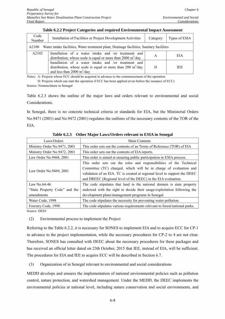
Republic of Senegal Chapter 6
Preparatory Survey for
Mamelles Sea Water Desalination Plant Construction Project Environmental and Social
Final Report Considerations
6-8
Table 6.2.2 Project Categories and required Environmental Impact Assessment
Code Number Installation of Facilities or Project Development Activities Category Types of ESIA
A2100 Water intake facilities, Water treatment plant, Drainage facilities, Sanitary facilities
A2102 Installation of a water intake and /or treatment and distribution, whose scale is equal or more than 2000 m3/day A EIA
Installation of a water intake and /or treatment and distribution, whose scale is equal or more than 200 m3/day and less than 2000 m3/day
D IEE
Notes: A: Projects whose ECC should be acquired in advance to the commencement of the operation D: Projects which can start the operation if ECC has been applied (even before the issuance of ECC)
Source: Nomenclature in Senegal
Table 6.2.3 shows the outline of the major laws and orders relevant to environmental and social Considerations.
In Senegal, there is no concrete technical criteria or standards for EIA, but the Ministerial Orders No.9471 (2001) and No.9472 (2001) regulates the outlines of the necessary contents of the TOR of the EIA.
Table 6.2.3 Other Major Laws/Orders relevant to ESIA in Senegal
Laws/Orders Main Contents Ministry Order No.9471, 2001 This order sets out the contents of an Terms of Reference (TOR) of EIA Ministry Order No.9472, 2001 This order sets out the contents of EIA reports. Law Order No.9468, 2001 This order is aimed at ensuring public participation in ESIA process.
Law Order No.9469, 2001
This order sets out the roles and responsibilities of the Technical Committee (TC) charged, which will be in charge of evaluation and validation of an EIA. TC is created at regional level to support the DEEC and DREEC (Regional level of the DEEC) in the EIA evaluation.
Law No.64-46 “State Property Code” and the amendments
The code stipulates that land in the national domain is state property endowed with the right to decide their usage/exploitation following the development plans/management programs in Senegal.
Water Code, 1998 The code stipulates the necessity for preventing water pollution. Forestry Code, 1998 The code stipulates various requirements relevant to forest/national parks.
Source: DEEC
(2) Environmental process to implement the Project
Referring to the Table 6.2.2, it is necessary for SONES to implement EIA and to acquire ECC for CP-1 in advance to the project implementation, while the necessary procedures for CP-2 to 4 are not clear. Therefore, SONES has consulted with DEEC about the necessary procedures for these packages and has received an official letter dated on 23th October, 2015 that IEE, instead of EIA, will be sufficient. The procedures for EIA and IEE to acquire ECC will be described in Section 6.7.
(3) Organization of in Senegal relevant to environmental and social considerations
MEDD develops and ensures the implementation of national environmental policies such as pollution control, nature protection, and watershed management. Under the MEDD, the DEEC implements the environmental policies at national level, including nature conservation and social environments, and
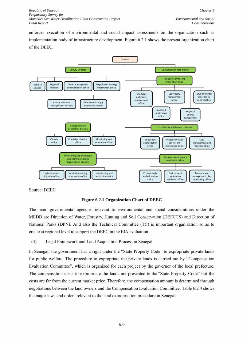
Republic of Senegal Chapter 6
Preparatory Survey for
Mamelles Sea Water Desalination Plant Construction Project Environmental and Social
Final Report Considerations
6-9
enforces execution of environmental and social impact assessments on the organization such as implementation body of infrastructure development. Figure 6.2.1 shows the present organization chart of the DEEC.
Source: DEEC
Figure 6.2.1 Organization Chart of DEEC
The main governmental agencies relevant to environmental and social considerations under the MEDD are Direction of Water, Forestry, Hunting and Soil Conservation (DEFCCS) and Direction of National Parks (DPN). And also the Technical Committee (TC) is important organization so as to create at regional level to support the DEEC in the EIA evaluation.
(4) Legal Framework and Land Acquisition Process in Senegal
In Senegal, the government has a right under the “State Property Code” to expropriate private lands for public welfare. The procedure to expropriate the private lands is carried out by “Compensation Evaluation Committee”, which is organized for each project by the governor of the local prefecture. The compensation costs to expropriate the lands are presented in the “State Property Code” but the costs are far from the current market price. Therefore, the compensation amount is determined through negotiations between the land owners and the Compensation Evaluation Committee. Table 6.2.4 shows the major laws and orders relevant to the land expropriation procedure in Senegal.
Director
Deputy Director Convention center of Bale
Pollution control and prevention office
Coastal climate protection division
Logistics technologyinformation office
General equipmentadministration office
Standard application
office
Coastal protection office
Natural resourcemanagement section
Finance and supply accounting section
Regionaldivision
Technicaladvisor
Climate office
Monitoring and evaluation office
Laboratory management
office
Chemical pollutants
managementoffice
Environmental emergency
control office
Regional quality
management
Environmental impact evaluation office
Project study and education
office
Environment management plan monitoring office
Environment evaluation
validation office
Monitoring and evaluation and communications legal affaires division
Monitoring and evaluation office
Sensitivity training information office
Legislation and litigation office
Classified establishment division
Inspection authorization
office
Pressure vessel control and
monitoring office
DataManagement and
recovery office
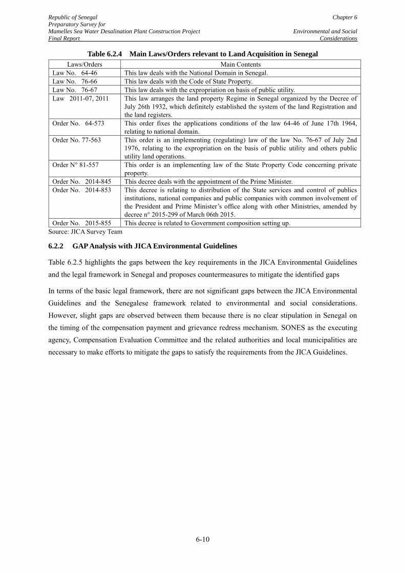
Republic of Senegal Chapter 6
Preparatory Survey for
Mamelles Sea Water Desalination Plant Construction Project Environmental and Social
Final Report Considerations
6-10
Table 6.2.4 Main Laws/Orders relevant to Land Acquisition in Senegal
Laws/Orders Main Contents Law No. 64-46 This law deals with the National Domain in Senegal. Law No. 76-66 This law deals with the Code of State Property. Law No. 76-67 This law deals with the expropriation on basis of public utility. Law 2011-07, 2011 This law arranges the land property Regime in Senegal organized by the Decree of
July 26th 1932, which definitely established the system of the land Registration and the land registers.
Order No. 64-573 This order fixes the applications conditions of the law 64-46 of June 17th 1964, relating to national domain.
Order No. 77-563 This order is an implementing (regulating) law of the law No. 76-67 of July 2nd 1976, relating to the expropriation on the basis of public utility and others public utility land operations.
Order N° 81-557 This order is an implementing law of the State Property Code concerning private property.
Order No. 2014-845 This decree deals with the appointment of the Prime Minister. Order No. 2014-853 This decree is relating to distribution of the State services and control of publics
institutions, national companies and public companies with common involvement of the President and Prime Minister’s office along with other Ministries, amended by decree n° 2015-299 of March 06th 2015.
Order No. 2015-855 This decree is related to Government composition setting up. Source: JICA Survey Team
6.2.2 GAP Analysis with JICA Environmental Guidelines
Table 6.2.5 highlights the gaps between the key requirements in the JICA Environmental Guidelines and the legal framework in Senegal and proposes countermeasures to mitigate the identified gaps
In terms of the basic legal framework, there are not significant gaps between the JICA Environmental Guidelines and the Senegalese framework related to environmental and social considerations. However, slight gaps are observed between them because there is no clear stipulation in Senegal on the timing of the compensation payment and grievance redress mechanism. SONES as the executing agency, Compensation Evaluation Committee and the related authorities and local municipalities are necessary to make efforts to mitigate the gaps to satisfy the requirements from the JICA Guidelines.
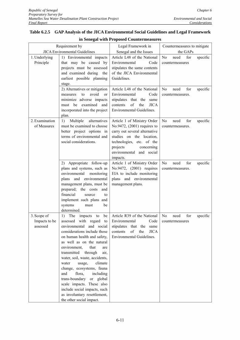
Republic of Senegal Chapter 6
Preparatory Survey for
Mamelles Sea Water Desalination Plant Construction Project Environmental and Social
Final Report Considerations
6-11
Table 6.2.5 GAP Analysis of the JICA Environmental Social Guidelines and Legal Framework
in Senegal with Proposed Countermeasures
Requirement by JICA Environmental Guidelines
Legal Framework in Senegal and the Issues
Countermeasures to mitigate the GAPs
1. Underlying Principle
1) Environmental impacts that may be caused by projects must be assessed and examined during the earliest possible planning stage.
Article L48 of the National Environmental Code stipulates the same contents of the JICA Environmental Guidelines.
No need for specific countermeasures
2) Alternatives or mitigation measures to avoid or minimize adverse impacts must be examined and incorporated into the project plan.
Article L48 of the National Environmental Code stipulates that the same contents of the JICA Environmental Guidelines.
No need for specific countermeasures.
2. Examination of Measures
1) Multiple alternatives must be examined to choose better project options in terms of environmental and social considerations.
Article 1 of Ministry Order No.9472, (2001) requires to carry out several alternative studies on the location, technologies, etc. of the projects concerning environmental and social impacts.
No need for specific countermeasures.
2) Appropriate follow-up plans and systems, such as environmental monitoring plans and environmental management plans, must be prepared; the costs and financial source to implement such plans and systems must be determined.
Article 1 of Ministry Order No.9472, (2001) requires EIA to include monitoring plans and environmental management plans.
No need for specific countermeasures.
3. Scope of Impacts to be assessed
1) The impacts to be assessed with regard to environmental and social considerations include those on human health and safety, as well as on the natural environment, that are transmitted through air, water, soil, waste, accidents, water usage, climate change, ecosystems, fauna and flora, including trans-boundary or global scale impacts. These also include social impacts, such as involuntary resettlement, the other social impact.
Article R39 of the National Environmental Code stipulates that the same contents of the JICA Environmental Guidelines.
No need for specific countermeasures
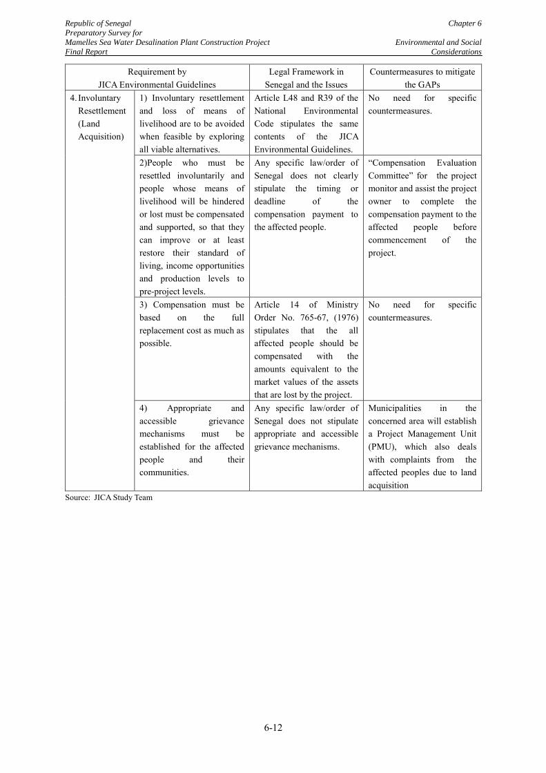
Republic of Senegal Chapter 6
Preparatory Survey for
Mamelles Sea Water Desalination Plant Construction Project Environmental and Social
Final Report Considerations
6-12
Requirement by JICA Environmental Guidelines
Legal Framework in Senegal and the Issues
Countermeasures to mitigate the GAPs
4. Involuntary Resettlement (Land Acquisition)
1) Involuntary resettlement and loss of means of livelihood are to be avoided when feasible by exploring all viable alternatives.
Article L48 and R39 of the National Environmental Code stipulates the same contents of the JICA Environmental Guidelines.
No need for specific countermeasures.
2)People who must be resettled involuntarily and people whose means of livelihood will be hindered or lost must be compensated and supported, so that they can improve or at least restore their standard of living, income opportunities and production levels to pre-project levels.
Any specific law/order of Senegal does not clearly stipulate the timing or deadline of the compensation payment to the affected people.
“Compensation Evaluation Committee” for the project monitor and assist the project owner to complete the compensation payment to the affected people before commencement of the project.
3) Compensation must be based on the full replacement cost as much as possible.
Article 14 of Ministry Order No. 765-67, (1976) stipulates that the all affected people should be compensated with the amounts equivalent to the market values of the assets that are lost by the project.
No need for specific countermeasures.
4) Appropriate and accessible grievance mechanisms must be established for the affected people and their communities.
Any specific law/order of Senegal does not stipulate appropriate and accessible grievance mechanisms.
Municipalities in the concerned area will establish a Project Management Unit (PMU), which also deals with complaints from the affected peoples due to land acquisition
Source: JICA Study Team
Republic of Senegal Chapter 6
Preparatory Survey for
Mamelles Sea Water Desalination Plant Construction Project Environmental and Social
Final Report Considerations
6-13
6.3 Alternative Analysis and Scoping
6.3.1 Alternative Analysis
The alternative analysis for environmental and social considerations is a comparative analysis to verify that the proposed project is the best of all the possible alternative projects including the “without project” alternative. This analysis is to be carried out with viewpoints of the possible environmental and social impacts, the cost and the other important factors.
(1) Alternative analysis of the water resources for additional water production
At first, based on the latest understandings on the present situation of available water resources for additional water production in the Dakar Region, the following three major alternatives analyzed are: i) zero option, ii) increase of water intake from Lac de Guiers, iii) construction of the Mamelles SWRO Plant.
In this alternative study, development of additional wells for large-scale groundwater extraction is not considered. Because the past study reports, and monitoring data indicate, lowering of groundwater, intrusion of seawater into groundwater and groundwater pollution. Additional extraction of groundwater is not a sustainable solution to meet the increasing water demand.
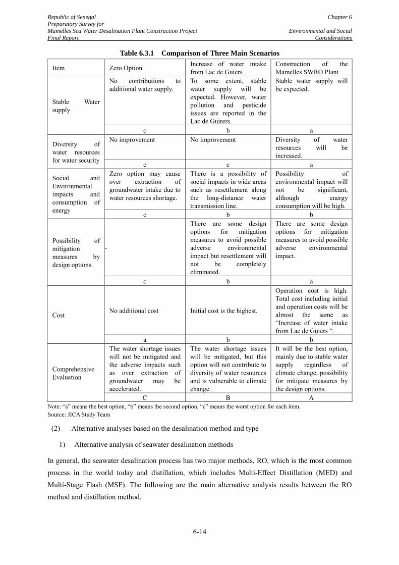
Republic of Senegal Chapter 6
Preparatory Survey for
Mamelles Sea Water Desalination Plant Construction Project Environmental and Social
Final Report Considerations
6-14
Table 6.3.1 Comparison of Three Main Scenarios
Item Zero Option Increase of water intake from Lac de Guiers
Construction of the Mamelles SWRO Plant
Stable Water supply
No contributions to additional water supply.
To some extent, stable water supply will be expected. However, water pollution and pesticide issues are reported in the Lac de Guirers.
Stable water supply will be expected.
c b a
Diversity of water resources for water security
No improvement No improvement Diversity of water resources will be increased.
c c a
Social and Environmental impacts and consumption of energy
Zero option may cause over extraction of groundwater intake due to water resources shortage.
There is a possibility of social impacts in wide areas such as resettlement along the long-distance water transmission line.
Possibility of environmental impact will not be significant, although energy consumption will be high.
c b b
Possibility of mitigation measures by design options.
-
There are some design options for mitigation measures to avoid possible adverse environmental impact but resettlement will not be completely eliminated.
There are some design options for mitigation measures to avoid possible adverse environmental impact.
c b a
Cost No additional cost Initial cost is the highest.
Operation cost is high. Total cost including initial and operation costs will be almost the same as “Increase of water intake from Lac de Guiers “.
a b b
Comprehensive Evaluation
The water shortage issues will not be mitigated and the adverse impacts such as over extraction of groundwater may be accelerated.
The water shortage issues will be mitigated, but this option will not contribute to diversity of water resources and is vulnerable to climate change.
It will be the best option, mainly due to stable water supply regardless of climate change, possibility for mitigate measures by the design options.
C B A Note: “a” means the best option, “b” means the second option, “c” means the worst option for each item. Source: JICA Study Team
(2) Alternative analyses based on the desalination method and type
1) Alternative analysis of seawater desalination methods
In general, the seawater desalination process has two major methods, RO, which is the most common process in the world today and distillation, which includes Multi-Effect Distillation (MED) and Multi-Stage Flash (MSF). The following are the main alternative analysis results between the RO method and distillation method.
Republic of Senegal Chapter 6
Preparatory Survey for
Mamelles Sea Water Desalination Plant Construction Project Environmental and Social
Final Report Considerations
6-15
Both methods need environmental considerations to avoid harmful impact on the eco-system by discharged saline water.
However, the RO method is advantageous to the distillation method in respect of energy consumption.
2) Alternative analysis by design of the sea water intake types
The seawater intake methods are divided into four major categories. The two selected possible methods for this project are the deep water intake method and seabed filtration method. The deep water intake method consists of “velocity cap” type and “tower” type, and the seabed filtration is divided into “seabed galley filtration” and “HDD collectors”.
Among the four types, the velocity cap type has been selected as this method takes into account possible environmental impacts (best option) and the project cost (second option) as described in Table 4.6.4 in Section 4.6.
3) Alternative analysis by design of the brine discharge types
The brine discharge methods are divided into four major categories. And the deep water discharge method is selected as a possible alternative for this project. The deep water discharge method is composed of three types; i) single nozzle, ii) multi-nozzle, iii) port riser.
As explained in Table 4.6.6. in Section 4.6, the port riser type has been selected by overall analysis of the cost, constructability and the potential impact on the marine ecosystems.
6.3.2 Scoping
Table 6.3.2 shows the scoping results based on the understandings of the initial step of the environmental and social impact evaluation.
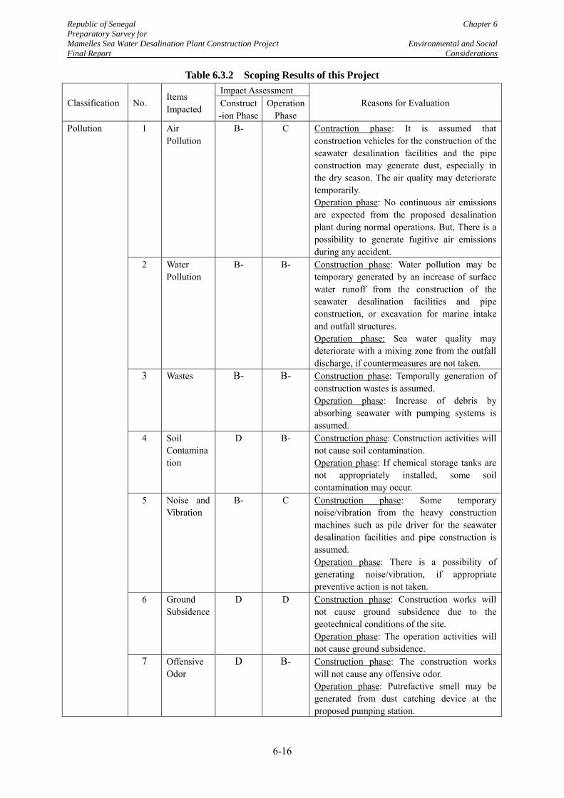
Republic of Senegal Chapter 6
Preparatory Survey for
Mamelles Sea Water Desalination Plant Construction Project Environmental and Social
Final Report Considerations
6-16
Table 6.3.2 Scoping Results of this Project
Classification No. Items Impacted
Impact Assessment Reasons for Evaluation Construct
-ion Phase Operation
Phase Pollution 1 Air
Pollution B- C Contraction phase: It is assumed that
construction vehicles for the construction of the seawater desalination facilities and the pipe construction may generate dust, especially in the dry season. The air quality may deteriorate temporarily. Operation phase: No continuous air emissions are expected from the proposed desalination plant during normal operations. But, There is a possibility to generate fugitive air emissions during any accident.
2 Water Pollution
B- B- Construction phase: Water pollution may be temporary generated by an increase of surface water runoff from the construction of the seawater desalination facilities and pipe construction, or excavation for marine intake and outfall structures. Operation phase: Sea water quality may deteriorate with a mixing zone from the outfall discharge, if countermeasures are not taken.
3 Wastes B- B- Construction phase: Temporally generation of construction wastes is assumed. Operation phase: Increase of debris by absorbing seawater with pumping systems is assumed.
4 Soil Contamination
D B- Construction phase: Construction activities will not cause soil contamination. Operation phase: If chemical storage tanks are not appropriately installed, some soil contamination may occur.
5 Noise and Vibration
B- C Construction phase: Some temporary noise/vibration from the heavy construction machines such as pile driver for the seawater desalination facilities and pipe construction is assumed. Operation phase: There is a possibility of generating noise/vibration, if appropriate preventive action is not taken.
6 Ground Subsidence
D D Construction phase: Construction works will not cause ground subsidence due to the geotechnical conditions of the site. Operation phase: The operation activities will not cause ground subsidence.
7 Offensive Odor
D B- Construction phase: The construction works will not cause any offensive odor. Operation phase: Putrefactive smell may be generated from dust catching device at the proposed pumping station.
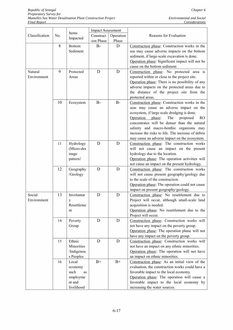
Republic of Senegal Chapter 6
Preparatory Survey for
Mamelles Sea Water Desalination Plant Construction Project Environmental and Social
Final Report Considerations
6-17
Classification No. Items Impacted
Impact Assessment Reasons for Evaluation Construct
-ion Phase Operation
Phase 8 Bottom
Sediment B- D Construction phase: Construction works in the
sea may cause adverse impacts on the bottom sediment, if large-scale excavation is done. Operation phase: Significant impact will not be cause on the bottom sediment.
Natural Environment
9 Protected Areas
D D Construction phase: No protected area is reported within or close to the project site. Operation phase: There is no possibility of any adverse impacts on the protected areas due to the distance of the project site from the protected areas.
10 Ecosystem B- B- Construction phase: Construction works in the seas may cause an adverse impact on the ecosystem, if large scale dredging is done. Operation phase: The proposed RO concentrates will be denser than the natural salinity and macro-benthic organisms may increase the risks to life. The increase of debris may cause an adverse impact on the ecosystem.
11 Hydrology (Micro-drainage pattern)
D D Construction phase: The construction works will not cause an impact on the present hydrology due to the location. Operation phase: The operation activities will not cause an impact on the present hydrology.
12 Geography/Geology
D D Construction phase: The construction works will not cause present geography/geology due to the scale of the construction. Operation phase: The operation could not cause impact on present geography/geology.
Social Environment
13 Involuntary Resettlement
D D Construction phase: No resettlement due to Project will occur, although small-scale land acquisition is needed. Operation phase: No resettlement due to the Project will occur.
14 Poverty Group
D D Construction phase: Construction works will not have any impact on the poverty group. Operation phase: The operation phase will not have any impact on the poverty group.
15 Ethnic Minorities /Indigenous Peoples
D D Construction phase: Construction works will not have an impact on any ethnic minorities. Operation phase: The operation will not have an impact on ethnic minorities.
16 Local economy such as employment and livelihood
B+ B+ Construction phase: As an initial view of the evaluation, the construction works could have a favorable impact to the local economy. Operation phase: The operation will cause a favorable impact to the local economy by increasing the water sources.
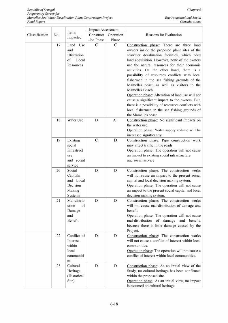
Republic of Senegal Chapter 6
Preparatory Survey for
Mamelles Sea Water Desalination Plant Construction Project Environmental and Social
Final Report Considerations
6-18
Classification No. Items Impacted
Impact Assessment Reasons for Evaluation Construct
-ion Phase Operation
Phase 17 Land Use
and Utilization of Local Resources
C C Construction phase: There are three land owners inside the proposed plant sites of the seawater desalination facilities, which need land acquisition. However, none of the owners use the natural resources for their economic activities. On the other hand, there is a possibility of resources conflicts with local fishermen in the sea fishing grounds of the Mamelles coast, as well as visitors to the Mamelles Beach. Operation phase: Alteration of land use will not cause a significant impact to the owners. But, there is a possibility of resources conflicts with local fishermen in the sea fishing grounds of the Mamelles coast.
18 Water Use D A+ Construction phase: No significant impacts on the water use. Operation phase: Water supply volume will be increased significantly.
19 Existing social infrastructure and social service
C D Construction phase: Pipe construction work may affect traffic in the roads Operation phase: The operation will not cause an impact to existing social infrastructure and social service
20 Social Capitals and Local Decision Making Systems
D D Construction phase: The construction works will not cause an impact to the present social capital and local decision making system. Operation phase: The operation will not cause an impact to the present social capital and local decision making system.
21 Mal-distribution of Damage and Benefit
D D Construction phase: The construction works will not cause mal-distribution of damage and benefit. Operation phase: The operation will not cause mal-distribution of damage and benefit, because there is little damage caused by the Project.
22 Conflict of Interest within local communities
D D Construction phase: The construction works will not cause a conflict of interest within local communities. Operation phase: The operation will not cause a conflict of interest within local communities.
23 Cultural Heritage (Historical Site)
D D Construction phase: As an initial view of the Study, no cultural heritage has been confirmed within the proposed site. Operation phase: As an initial view, no impact is assumed on cultural heritage.
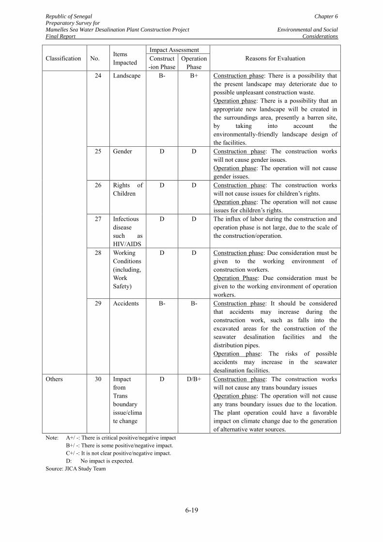
Republic of Senegal Chapter 6
Preparatory Survey for
Mamelles Sea Water Desalination Plant Construction Project Environmental and Social
Final Report Considerations
6-19
Classification No. Items Impacted
Impact Assessment Reasons for Evaluation Construct
-ion Phase Operation
Phase 24 Landscape B- B+ Construction phase: There is a possibility that
the present landscape may deteriorate due to possible unpleasant construction waste. Operation phase: There is a possibility that an appropriate new landscape will be created in the surroundings area, presently a barren site, by taking into account the environmentally-friendly landscape design of the facilities.
25 Gender D D Construction phase: The construction works will not cause gender issues. Operation phase: The operation will not cause gender issues.
26 Rights of Children
D D Construction phase: The construction works will not cause issues for children’s rights. Operation phase: The operation will not cause issues for children’s rights.
27 Infectious disease such as HIV/AIDS
D D The influx of labor during the construction and operation phase is not large, due to the scale of the construction/operation.
28 Working Conditions (including, Work Safety)
D D Construction phase: Due consideration must be given to the working environment of construction workers. Operation Phase: Due consideration must be given to the working environment of operation workers.
29 Accidents B- B- Construction phase: It should be considered that accidents may increase during the construction work, such as falls into the excavated areas for the construction of the seawater desalination facilities and the distribution pipes. Operation phase: The risks of possible accidents may increase in the seawater desalination facilities.
Others 30 Impact from Trans boundary issue/climate change
D D/B+ Construction phase: The construction works will not cause any trans boundary issues Operation phase: The operation will not cause any trans boundary issues due to the location. The plant operation could have a favorable impact on climate change due to the generation of alternative water sources.
Note: A+/ -: There is critical positive/negative impact B+/ -: There is some positive/negative impact. C+/ -: It is not clear positive/negative impact. D: No impact is expected. Source: JICA Study Team
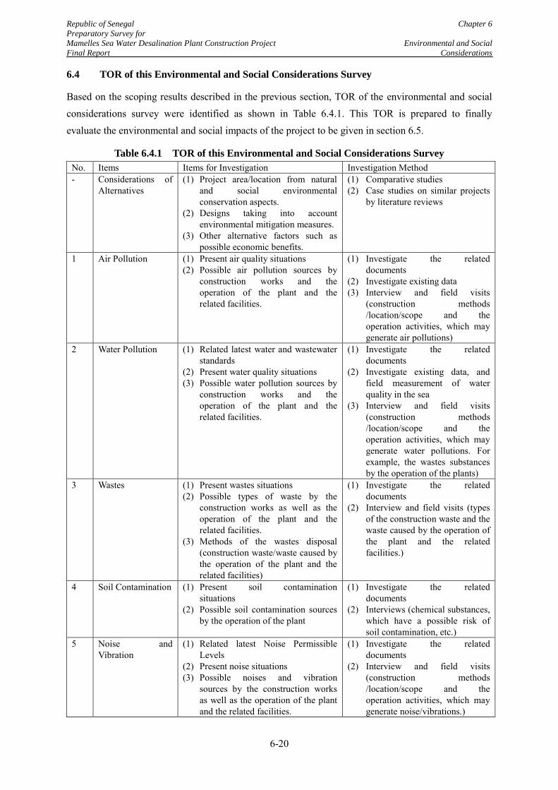
Republic of Senegal Chapter 6
Preparatory Survey for
Mamelles Sea Water Desalination Plant Construction Project Environmental and Social
Final Report Considerations
6-20
6.4 TOR of this Environmental and Social Considerations Survey
Based on the scoping results described in the previous section, TOR of the environmental and social considerations survey were identified as shown in Table 6.4.1. This TOR is prepared to finally evaluate the environmental and social impacts of the project to be given in section 6.5.
Table 6.4.1 TOR of this Environmental and Social Considerations Survey
No. Items Items for Investigation Investigation Method - Considerations of
Alternatives
(1) Project area/location from natural and social environmental conservation aspects.
(2) Designs taking into account environmental mitigation measures.
(3) Other alternative factors such as possible economic benefits.
(1) Comparative studies (2) Case studies on similar projects
by literature reviews
1 Air Pollution (1) Present air quality situations (2) Possible air pollution sources by
construction works and the operation of the plant and the related facilities.
(1) Investigate the related documents
(2) Investigate existing data (3) Interview and field visits
(construction methods /location/scope and the operation activities, which may generate air pollutions)
2 Water Pollution (1) Related latest water and wastewater standards
(2) Present water quality situations (3) Possible water pollution sources by
construction works and the operation of the plant and the related facilities.
(1) Investigate the related documents
(2) Investigate existing data, and field measurement of water quality in the sea
(3) Interview and field visits (construction methods /location/scope and the operation activities, which may generate water pollutions. For example, the wastes substances by the operation of the plants)
3 Wastes (1) Present wastes situations (2) Possible types of waste by the
construction works as well as the operation of the plant and the related facilities.
(3) Methods of the wastes disposal (construction waste/waste caused by the operation of the plant and the related facilities)
(1) Investigate the related documents
(2) Interview and field visits (types of the construction waste and the waste caused by the operation of the plant and the related facilities.)
4 Soil Contamination (1) Present soil contamination situations
(2) Possible soil contamination sources by the operation of the plant
(1) Investigate the related documents
(2) Interviews (chemical substances, which have a possible risk of soil contamination, etc.)
5 Noise and Vibration
(1) Related latest Noise Permissible Levels
(2) Present noise situations (3) Possible noises and vibration
sources by the construction works as well as the operation of the plant and the related facilities.
(1) Investigate the related documents
(2) Interview and field visits (construction methods /location/scope and the operation activities, which may generate noise/vibrations.)
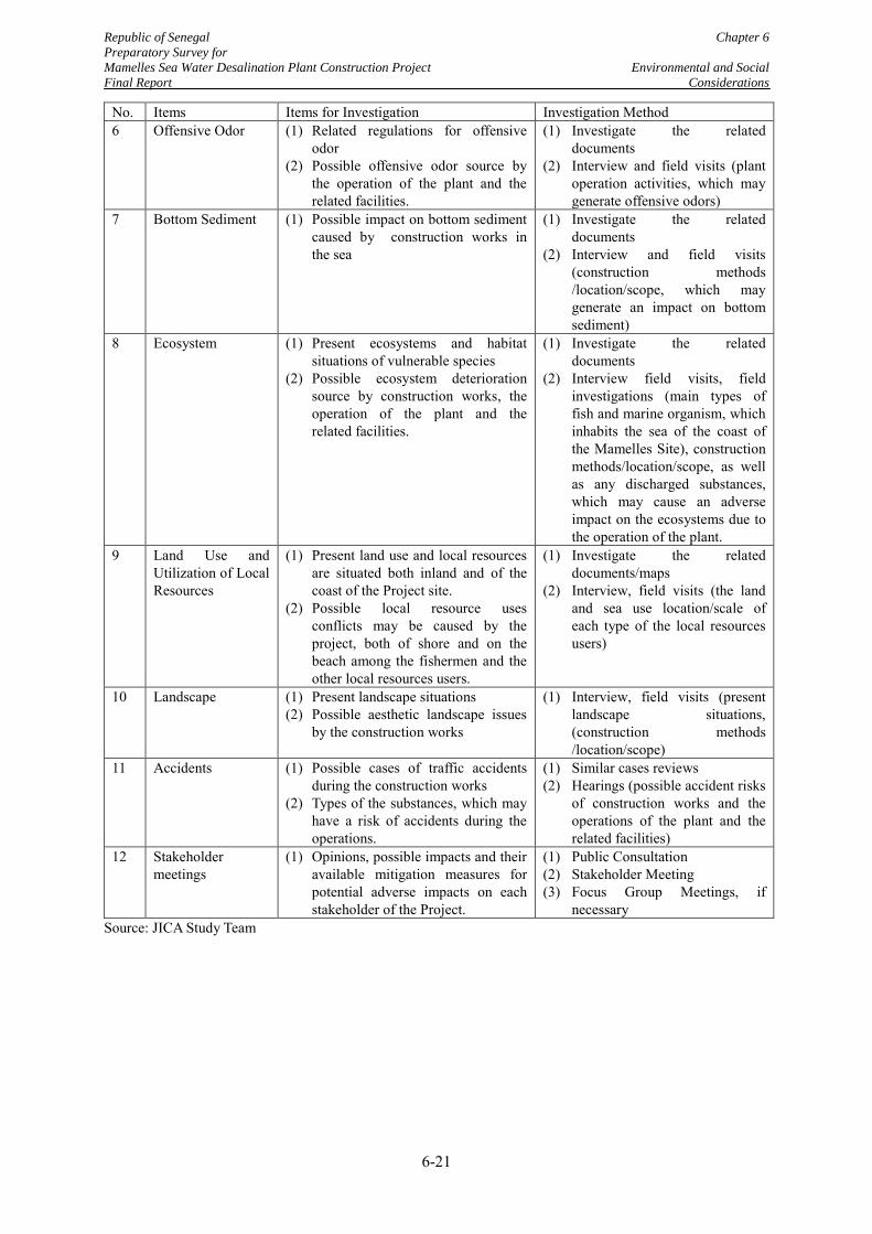
Republic of Senegal Chapter 6
Preparatory Survey for
Mamelles Sea Water Desalination Plant Construction Project Environmental and Social
Final Report Considerations
6-21
No. Items Items for Investigation Investigation Method 6 Offensive Odor (1) Related regulations for offensive
odor (2) Possible offensive odor source by
the operation of the plant and the related facilities.
(1) Investigate the related documents
(2) Interview and field visits (plant operation activities, which may generate offensive odors)
7 Bottom Sediment (1) Possible impact on bottom sediment caused by construction works in the sea
(1) Investigate the related documents
(2) Interview and field visits (construction methods /location/scope, which may generate an impact on bottom sediment)
8 Ecosystem (1) Present ecosystems and habitat situations of vulnerable species
(2) Possible ecosystem deterioration source by construction works, the operation of the plant and the related facilities.
(1) Investigate the related documents
(2) Interview field visits, field investigations (main types of fish and marine organism, which inhabits the sea of the coast of the Mamelles Site), construction methods/location/scope, as well as any discharged substances, which may cause an adverse impact on the ecosystems due to the operation of the plant.
9 Land Use and Utilization of Local Resources
(1) Present land use and local resources are situated both inland and of the coast of the Project site.
(2) Possible local resource uses conflicts may be caused by the project, both of shore and on the beach among the fishermen and the other local resources users.
(1) Investigate the related documents/maps
(2) Interview, field visits (the land and sea use location/scale of each type of the local resources users)
10 Landscape (1) Present landscape situations (2) Possible aesthetic landscape issues
by the construction works
(1) Interview, field visits (present landscape situations, (construction methods /location/scope)
11 Accidents (1) Possible cases of traffic accidents during the construction works
(2) Types of the substances, which may have a risk of accidents during the operations.
(1) Similar cases reviews (2) Hearings (possible accident risks
of construction works and the operations of the plant and the related facilities)
12 Stakeholder meetings
(1) Opinions, possible impacts and their available mitigation measures for potential adverse impacts on each stakeholder of the Project.
(1) Public Consultation (2) Stakeholder Meeting (3) Focus Group Meetings, if
necessary Source: JICA Study Team
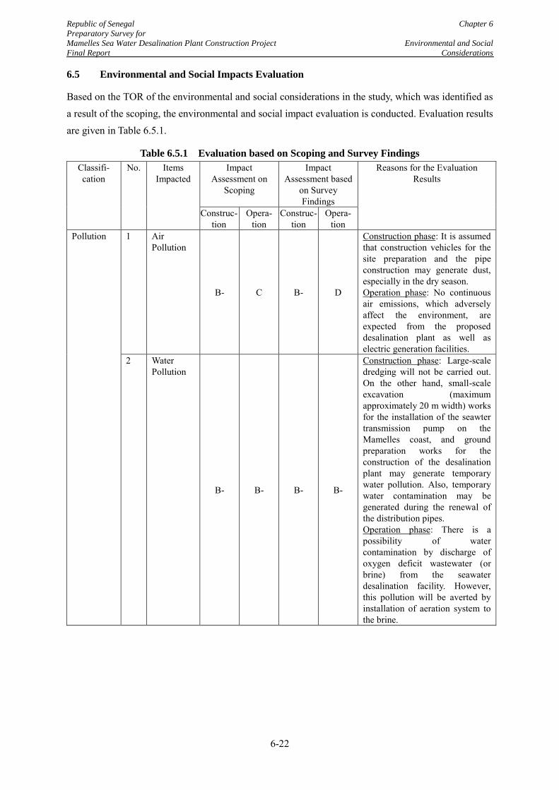
Republic of Senegal Chapter 6
Preparatory Survey for
Mamelles Sea Water Desalination Plant Construction Project Environmental and Social
Final Report Considerations
6-22
6.5 Environmental and Social Impacts Evaluation
Based on the TOR of the environmental and social considerations in the study, which was identified as a result of the scoping, the environmental and social impact evaluation is conducted. Evaluation results are given in Table 6.5.1.
Table 6.5.1 Evaluation based on Scoping and Survey Findings
Classifi- cation
No. Items Impacted
Impact Assessment on
Scoping
Impact Assessment based
on Survey Findings
Reasons for the Evaluation Results
Construc-tion
Opera- tion
Construc-tion
Opera- tion
Pollution 1
Air Pollution
B- C B- D
Construction phase: It is assumed that construction vehicles for the site preparation and the pipe construction may generate dust, especially in the dry season. Operation phase: No continuous air emissions, which adversely affect the environment, are expected from the proposed desalination plant as well as electric generation facilities.
2 Water Pollution
B- B- B- B-
Construction phase: Large-scale dredging will not be carried out. On the other hand, small-scale excavation (maximum approximately 20 m width) works for the installation of the seawter transmission pump on the Mamelles coast, and ground preparation works for the construction of the desalination plant may generate temporary water pollution. Also, temporary water contamination may be generated during the renewal of the distribution pipes. Operation phase: There is a possibility of water contamination by discharge of oxygen deficit wastewater (or brine) from the seawater desalination facility. However, this pollution will be averted by installation of aeration system to the brine.
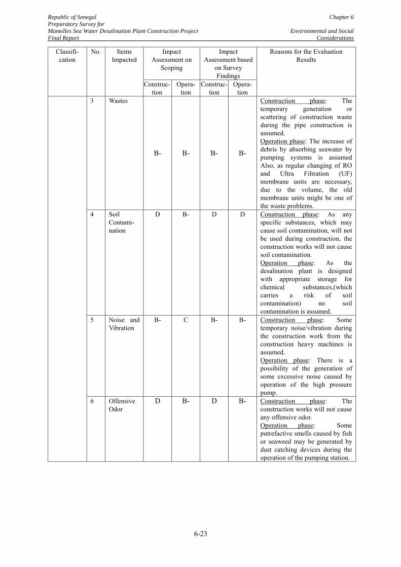
Republic of Senegal Chapter 6
Preparatory Survey for
Mamelles Sea Water Desalination Plant Construction Project Environmental and Social
Final Report Considerations
6-23
Classifi- cation
No. Items Impacted
Impact Assessment on
Scoping
Impact Assessment based
on Survey Findings
Reasons for the Evaluation Results
Construc-tion
Opera- tion
Construc-tion
Opera- tion
3 Wastes
B- B- B- B-
Construction phase: The temporary generation or scattering of construction waste during the pipe construction is assumed. Operation phase: The increase of debris by absorbing seawater by pumping systems is assumed Also, as regular changing of RO and Ultra Filtration (UF) membrane units are necessary, due to the volume, the old membrane units might be one of the waste problems.
4 Soil Contami- nation
D B- D D Construction phase: As any specific substances, which may cause soil contamination, will not be used during construction, the construction works will not cause soil contamination. Operation phase: As the desalination plant is designed with appropriate storage for chemical substances,(which carries a risk of soil contamination) no soil contamination is assumed.
5 Noise and Vibration
B- C B- B- Construction phase: Some temporary noise/vibration during the construction work from the construction heavy machines is assumed. Operation phase: There is a possibility of the generation of some excessive noise caused by operation of the high pressure pump.
6 Offensive Odor
D B- D B- Construction phase: The construction works will not cause any offensive odor. Operation phase: Some putrefactive smells caused by fish or seaweed may be generated by dust catching devices during the operation of the pumping station.
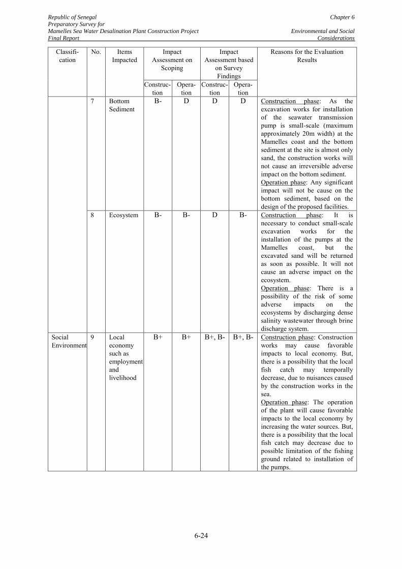
Republic of Senegal Chapter 6
Preparatory Survey for
Mamelles Sea Water Desalination Plant Construction Project Environmental and Social
Final Report Considerations
6-24
Classifi- cation
No. Items Impacted
Impact Assessment on
Scoping
Impact Assessment based
on Survey Findings
Reasons for the Evaluation Results
Construc-tion
Opera- tion
Construc-tion
Opera- tion
7 Bottom Sediment
B- D D D Construction phase: As the excavation works for installation of the seawater transmission pump is small-scale (maximum approximately 20m width) at the Mamelles coast and the bottom sediment at the site is almost only sand, the construction works will not cause an irreversible adverse impact on the bottom sediment. Operation phase: Any significant impact will not be cause on the bottom sediment, based on the design of the proposed facilities.
8 Ecosystem B- B- D B- Construction phase: It is necessary to conduct small-scale excavation works for the installation of the pumps at the Mamelles coast, but the excavated sand will be returned as soon as possible. It will not cause an adverse impact on the ecosystem. Operation phase: There is a possibility of the risk of some adverse impacts on the ecosystems by discharging dense salinity wastewater through brine discharge system.
Social Environment
9 Local economy such as employment and livelihood
B+ B+ B+, B- B+, B- Construction phase: Construction works may cause favorable impacts to local economy. But, there is a possibility that the local fish catch may temporally decrease, due to nuisances caused by the construction works in the sea. Operation phase: The operation of the plant will cause favorable impacts to the local economy by increasing the water sources. But, there is a possibility that the local fish catch may decrease due to possible limitation of the fishing ground related to installation of the pumps.
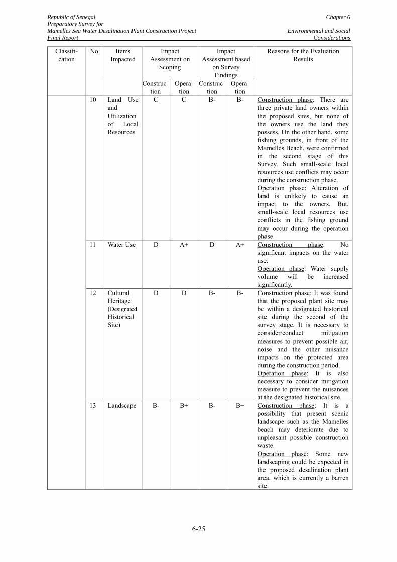
Republic of Senegal Chapter 6
Preparatory Survey for
Mamelles Sea Water Desalination Plant Construction Project Environmental and Social
Final Report Considerations
6-25
Classifi- cation
No. Items Impacted
Impact Assessment on
Scoping
Impact Assessment based
on Survey Findings
Reasons for the Evaluation Results
Construc-tion
Opera- tion
Construc-tion
Opera- tion
10 Land Use and Utilization of Local Resources
C C B- B- Construction phase: There are three private land owners within the proposed sites, but none of the owners use the land they possess. On the other hand, some fishing grounds, in front of the Mamelles Beach, were confirmed in the second stage of this Survey. Such small-scale local resources use conflicts may occur during the construction phase. Operation phase: Alteration of land is unlikely to cause an impact to the owners. But, small-scale local resources use conflicts in the fishing ground may occur during the operation phase.
11 Water Use D A+ D A+ Construction phase: No significant impacts on the water use. Operation phase: Water supply volume will be increased significantly.
12 Cultural Heritage (Designated Historical Site)
D D B- B- Construction phase: It was found that the proposed plant site may be within a designated historical site during the second of the survey stage. It is necessary to consider/conduct mitigation measures to prevent possible air, noise and the other nuisance impacts on the protected area during the construction period. Operation phase: It is also necessary to consider mitigation measure to prevent the nuisances at the designated historical site.
13 Landscape B- B+ B- B+ Construction phase: It is a possibility that present scenic landscape such as the Mamelles beach may deteriorate due to unpleasant possible construction waste. Operation phase: Some new landscaping could be expected in the proposed desalination plant area, which is currently a barren site.
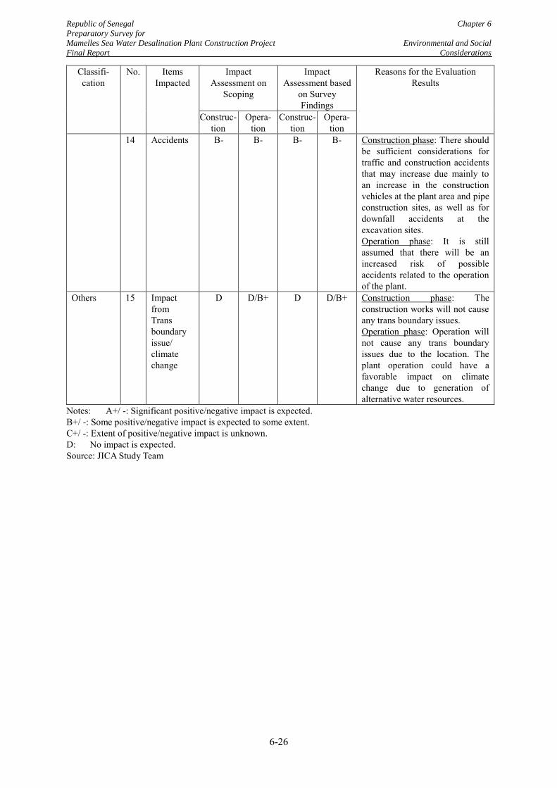
Republic of Senegal Chapter 6
Preparatory Survey for
Mamelles Sea Water Desalination Plant Construction Project Environmental and Social
Final Report Considerations
6-26
Classifi- cation
No. Items Impacted
Impact Assessment on
Scoping
Impact Assessment based
on Survey Findings
Reasons for the Evaluation Results
Construc-tion
Opera- tion
Construc-tion
Opera- tion
14 Accidents B- B- B- B- Construction phase: There should be sufficient considerations for traffic and construction accidents that may increase due mainly to an increase in the construction vehicles at the plant area and pipe construction sites, as well as for downfall accidents at the excavation sites. Operation phase: It is still assumed that there will be an increased risk of possible accidents related to the operation of the plant.
Others 15 Impact from Trans boundary issue/ climate change
D D/B+ D D/B+ Construction phase: The construction works will not cause any trans boundary issues. Operation phase: Operation will not cause any trans boundary issues due to the location. The plant operation could have a favorable impact on climate change due to generation of alternative water resources.
Notes: A+/ -: Significant positive/negative impact is expected. B+/ -: Some positive/negative impact is expected to some extent. C+/ -: Extent of positive/negative impact is unknown. D: No impact is expected. Source: JICA Study Team
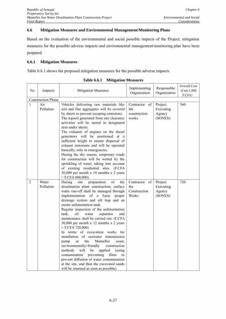
Republic of Senegal Chapter 6
Preparatory Survey for
Mamelles Sea Water Desalination Plant Construction Project Environmental and Social
Final Report Considerations
6-27
6.6 Mitigation Measures and Environmental Management/Monitoring Plans
Based on the evaluation of the environmental and social possible impacts of the Project, mitigation measures for the possible adverse impacts and environmental management/monitoring plan have been prepared.
6.6.1 Mitigation Measures
Table 6.6.1 shows the proposed mitigation measures for the possible adverse impacts.
Table 6.6.1 Mitigation Measures
No Impacts Mitigation Measures Implementing Organization
Responsible Organization
Overall Cost (Unit:1,000
F.CFA) Construction Phase 1 Air
Pollution Vehicles delivering raw materials like soil and fine aggregates will be covered by sheets to prevent escaping emissions. The topsoil generated from site clearance activities will be stored in designated area under sheets. The exhausts of engines on the diesel generators will be positioned at a sufficient height to ensure dispersal of exhaust emissions and will be operated basically, only in emergencies. During the dry season, temporary roads for construction will be wetted by the sprinkling of water, taking into account of existing residential sites. (F.CFA 30,000 per month x 10 months x 2 years = F.CFA 600,000)
Contractor of the construction works
Project Executing Agency (SONES)
360
2 Water Pollution
During site preparation of the desalination plant construction, surface water run-off shall be managed through implementation of a basic proper drainage system and silt trap and an onsite sedimentation tank. Regular inspection of the sedimentation tank, oil water separator and maintenance shall be carried out. (F.CFA 30,000 per month x 12 months x 2 years = F.CFA 720,000) In terms of excavation works for installation of seawater transmission pump at the Mamelles coast, environmentally-friendly construction methods will be applied (using contamination preventing films to prevent diffusion of water contamination at the site, and then the excavated sands will be returned as soon as possible)
Contractor of the Construction Works
Project Executing Agency (SONES)
720
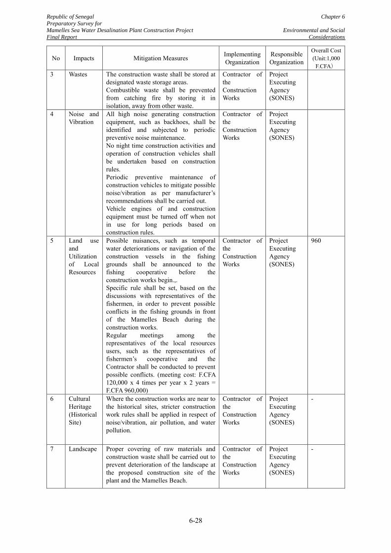
Republic of Senegal Chapter 6
Preparatory Survey for
Mamelles Sea Water Desalination Plant Construction Project Environmental and Social
Final Report Considerations
6-28
No Impacts Mitigation Measures Implementing Organization
Responsible Organization
Overall Cost (Unit:1,000
F.CFA) 3 Wastes
The construction waste shall be stored at designated waste storage areas. Combustible waste shall be prevented from catching fire by storing it in isolation, away from other waste.
Contractor of the Construction Works
Project Executing Agency (SONES)
4 Noise and Vibration
All high noise generating construction equipment, such as backhoes, shall be identified and subjected to periodic preventive noise maintenance. No night time construction activities and operation of construction vehicles shall be undertaken based on construction rules. Periodic preventive maintenance of construction vehicles to mitigate possible noise/vibration as per manufacturer’s recommendations shall be carried out. Vehicle engines of and construction equipment must be turned off when not in use for long periods based on construction rules.
Contractor of the Construction Works
Project Executing Agency (SONES)
5 Land use and Utilization of Local Resources
Possible nuisances, such as temporal water deteriorations or navigation of the construction vessels in the fishing grounds shall be announced to the fishing cooperative before the construction works begin.,. Specific rule shall be set, based on the discussions with representatives of the fishermen, in order to prevent possible conflicts in the fishing grounds in front of the Mamelles Beach during the construction works. Regular meetings among the representatives of the local resources users, such as the representatives of fishermen’s cooperative and the Contractor shall be conducted to prevent possible conflicts. (meeting cost: F.CFA 120,000 x 4 times per year x 2 years = F.CFA 960,000)
Contractor of the Construction Works
Project Executing Agency (SONES)
960
6 Cultural Heritage (Historical Site)
Where the construction works are near to the historical sites, stricter construction work rules shall be applied in respect of noise/vibration, air pollution, and water pollution.
Contractor of the Construction Works
Project Executing Agency (SONES)
-
7 Landscape Proper covering of raw materials and construction waste shall be carried out to prevent deterioration of the landscape at the proposed construction site of the plant and the Mamelles Beach.
Contractor of the Construction Works
Project Executing Agency (SONES)
-
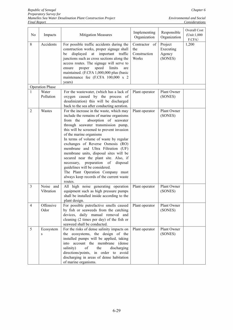
Republic of Senegal Chapter 6
Preparatory Survey for
Mamelles Sea Water Desalination Plant Construction Project Environmental and Social
Final Report Considerations
6-29
No Impacts Mitigation Measures Implementing Organization
Responsible Organization
Overall Cost (Unit:1,000
F.CFA) 8 Accidents
For possible traffic accidents during the construction works, proper signage shall be displayed at important traffic junctions such as cross sections along the access routes. The signage will serve to ensure proper speed limits are maintained. (F.CFA 1,000,000 plus (basic maintenance fee (F.CFA 100,000 x 2 years)
Contractor of the Construction Works
Project Executing Agency (SONES)
1,200
Operation Phase 1 Water
Pollution For the wastewater, (which has a lack of oxygen caused by the process of desalinization) this will be discharged back to the sea after conducting aeration.
Plant operator Plant Owner (SONES)
2 Wastes
For the increase in the waste, which may include the remains of marine organisms from the absorption of seawater through seawater transmission pump, this will be screened to prevent invasion of the marine organisms In terms of volume of waste by regular exchanges of Reverse Osmosis (RO) membrane and Ultra Filtration (UF) membrane units, disposal sites will be secured near the plant site. Also, if necessary, preparation of disposal guidelines will be considered. The Plant Operation Company must always keep records of the current waste routes.
Plant operator Plant Owner (SONES)
3 Noise and Vibration
All high noise generating operation equipment such as high pressure pumps shall be installed inside according to the plant design.
Plant operator Plant Owner (SONES)
4 Offensive Odor
For possible putrefactive smells caused by fish or seaweeds from the catching devices, daily manual removal and cleaning (2 times per day) of the fish or seaweed shall be conducted.
Plant operator Plant Owner (SONES)
5 Ecosystems
For the risks of dense salinity impacts on the ecosystems, the design of the installed pumps will be applied, taking into account the membrane (dense salinity) of the discharging directions/points, in order to avoid discharging in areas of dense habitation of marine organisms.
Plant operator Plant Owner (SONES)
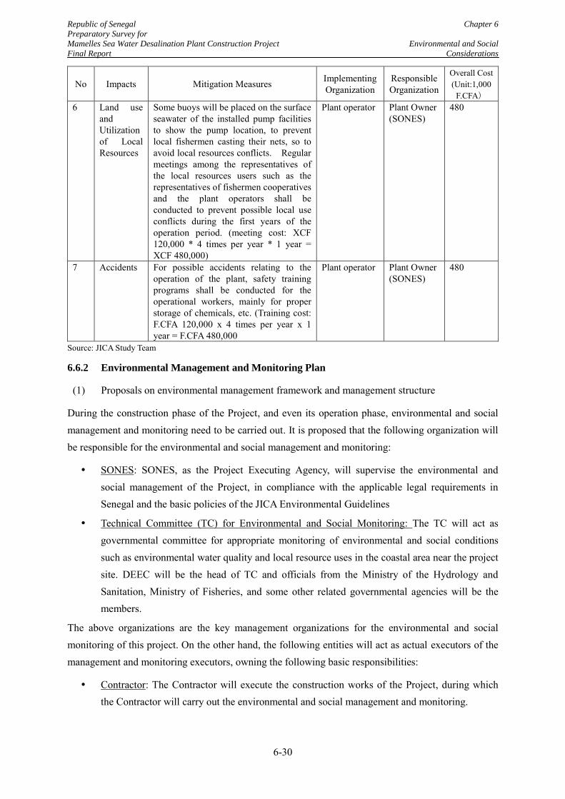
Republic of Senegal Chapter 6
Preparatory Survey for
Mamelles Sea Water Desalination Plant Construction Project Environmental and Social
Final Report Considerations
6-30
No Impacts Mitigation Measures Implementing Organization
Responsible Organization
Overall Cost (Unit:1,000
F.CFA) 6 Land use
and Utilization of Local Resources
Some buoys will be placed on the surface seawater of the installed pump facilities to show the pump location, to prevent local fishermen casting their nets, so to avoid local resources conflicts. Regular meetings among the representatives of the local resources users such as the representatives of fishermen cooperatives and the plant operators shall be conducted to prevent possible local use conflicts during the first years of the operation period. (meeting cost: XCF 120,000 * 4 times per year * 1 year = XCF 480,000)
Plant operator Plant Owner (SONES)
480
7 Accidents For possible accidents relating to the operation of the plant, safety training programs shall be conducted for the operational workers, mainly for proper storage of chemicals, etc. (Training cost: F.CFA 120,000 x 4 times per year x 1 year = F.CFA 480,000
Plant operator Plant Owner (SONES)
480
Source: JICA Study Team
6.6.2 Environmental Management and Monitoring Plan
(1) Proposals on environmental management framework and management structure
During the construction phase of the Project, and even its operation phase, environmental and social management and monitoring need to be carried out. It is proposed that the following organization will be responsible for the environmental and social management and monitoring:
SONES: SONES, as the Project Executing Agency, will supervise the environmental and social management of the Project, in compliance with the applicable legal requirements in Senegal and the basic policies of the JICA Environmental Guidelines
Technical Committee (TC) for Environmental and Social Monitoring: The TC will act as governmental committee for appropriate monitoring of environmental and social conditions such as environmental water quality and local resource uses in the coastal area near the project site. DEEC will be the head of TC and officials from the Ministry of the Hydrology and Sanitation, Ministry of Fisheries, and some other related governmental agencies will be the members.
The above organizations are the key management organizations for the environmental and social monitoring of this project. On the other hand, the following entities will act as actual executors of the management and monitoring executors, owning the following basic responsibilities:
Contractor: The Contractor will execute the construction works of the Project, during which the Contractor will carry out the environmental and social management and monitoring.
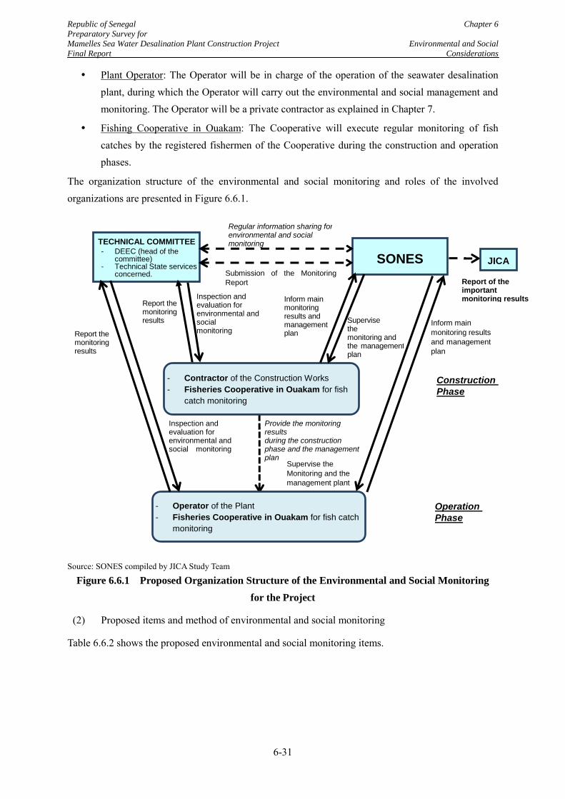
Republic of Senegal Chapter 6
Preparatory Survey for
Mamelles Sea Water Desalination Plant Construction Project Environmental and Social
Final Report Considerations
6-31
Plant Operator: The Operator will be in charge of the operation of the seawater desalination plant, during which the Operator will carry out the environmental and social management and monitoring. The Operator will be a private contractor as explained in Chapter 7.
Fishing Cooperative in Ouakam: The Cooperative will execute regular monitoring of fish catches by the registered fishermen of the Cooperative during the construction and operation phases.
The organization structure of the environmental and social monitoring and roles of the involved organizations are presented in Figure 6.6.1.
Source: SONES compiled by JICA Study Team
Figure 6.6.1 Proposed Organization Structure of the Environmental and Social Monitoring
for the Project
(2) Proposed items and method of environmental and social monitoring
Table 6.6.2 shows the proposed environmental and social monitoring items.
Submission of the Monitoring
Report
Inspection and evaluation for environmental and social monitoring
Inform main
monitoring results
and management
plan
SONES
Regular information sharing for environmental and social monitoring
Supervise the
Monitoring and the
management plant
JICA
Report of the important monitoring results
TECHNICAL COMMITTEE - DEEC (head of the
committee) - Technical State services
concerned.
Construction
Phase
Operation
Phase
Inspection and evaluation for environmental and social monitoring
- Operator of the Plant
- Fisheries Cooperative in Ouakam for fish catch
monitoring
Provide the monitoring results during the construction phase and the management plan
- Contractor of the Construction Works
- Fisheries Cooperative in Ouakam for fish
catch monitoring
Inform main monitoring results and management plan
Supervise the monitoring and the management plan
Report the monitoring results
Report the monitoring results
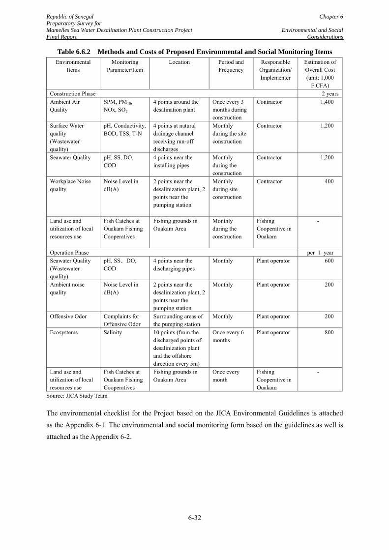
Republic of Senegal Chapter 6
Preparatory Survey for
Mamelles Sea Water Desalination Plant Construction Project Environmental and Social
Final Report Considerations
6-32
Table 6.6.2 Methods and Costs of Proposed Environmental and Social Monitoring Items
Environmental Items
Monitoring Parameter/Item
Location Period and Frequency
Responsible Organization/ Implementer
Estimation of Overall Cost (unit: 1,000
F.CFA) Construction Phase 2 years Ambient Air Quality
SPM, PM10, NOx, SO2
4 points around the desalination plant
Once every 3 months during construction
Contractor 1,400
Surface Water quality (Wastewater quality)
pH, Conductivity, BOD, TSS, T-N
4 points at natural drainage channel receiving run-off discharges
Monthly during the site construction
Contractor 1,200
Seawater Quality pH, SS, DO, COD
4 points near the installing pipes
Monthly during the construction
Contractor 1,200
Workplace Noise quality
Noise Level in dB(A)
2 points near the desalinization plant, 2 points near the pumping station
Monthly during site construction
Contractor 400
Land use and utilization of local resources use
Fish Catches at Ouakam Fishing Cooperatives
Fishing grounds in Ouakam Area
Monthly during the construction
Fishing Cooperative in Ouakam
-
Operation Phase per 1 year Seawater Quality (Wastewater quality)
pH, SS、DO, COD
4 points near the discharging pipes
Monthly Plant operator 600
Ambient noise quality
Noise Level in dB(A)
2 points near the desalinization plant, 2 points near the pumping station
Monthly Plant operator 200
Offensive Odor Complaints for Offensive Odor
Surrounding areas of the pumping station
Monthly Plant operator 200
Ecosystems Salinity 10 points (from the discharged points of desalinization plant and the offshore direction every 5m)
Once every 6 months
Plant operator 800
Land use and utilization of local resources use
Fish Catches at Ouakam Fishing Cooperatives
Fishing grounds in Ouakam Area
Once every month
Fishing Cooperative in Ouakam
-
Source: JICA Study Team
The environmental checklist for the Project based on the JICA Environmental Guidelines is attached as the Appendix 6-1. The environmental and social monitoring form based on the guidelines as well is attached as the Appendix 6-2.
Republic of Senegal Chapter 6
Preparatory Survey for
Mamelles Sea Water Desalination Plant Construction Project Environmental and Social
Final Report Considerations
6-33
6.7 Progress of the Environmental and Social considerations Impact Assessment (ESIA) by
SONES and Expected Schedule
6.7.1 EIA study for the Construction of the Seawater Desalination Plant
(1) Review of the TOR of the EIA Study
The EIA Study is required for the construction of the seawater desalination plant in the Project. The EIA Study will be carried out by SONES, entrusting the study works to consultants. The study will cover the area of the proposed desalination plant and the related facilities area.
The TOR of the EIA Study has already been approved by DEEC. On the other hand, JICA Study Team has reviewed the approved TOR of the EIA Study taking into account the JICA Environmental Guidelines.
As a result of the review, it is understood that the overall contents of the TOR of the EIA Study meet the basic policies of the JICA Guidelines. However, the JICA Study Team points out that the TOR does not describe the methodologies of the study in detail. It is assumed that the detailed methodologies will be planned and proposed by the consultant, but the JICA Study Team recommends that the following contents should be considered or be clarified when the EIA Study commences.
Implementation of the public hearing as soon as possible, which collects citizen opinions about the Project
Inclusion of air quality item as one of the potential environmental impacts and impact assessment
Clarification of concrete sampling or measuring points for each survey item
(2) Procedure and necessary duration for EIA approval
As mentioned in Subsections 6.2.1 and 6.2.2, the National Environmental Code of Senegal stipulates the concept of ESIA. However, the related procedures of the environmental assessment and the necessary or estimated duration are not described in any relevant regulation/guideline in Senegal.
Figure 6.7.1 shows the general EIA procedure until issuance of the ECC in Senegal. According to the interview to the Chief of the Environmental Impact Assessment Division of the DEEC, the estimated duration for issuance of the Environmental Compliance Certificate (ECC) in Senegal, is generally six months after DECC’s approval to TOR of EIA study, although there is no legal base for the duration mentioned. In the interview above, it was also mentioned that the duration depends on the scale of the project, or significance of the possible adverse impacts caused by the activities of the project.
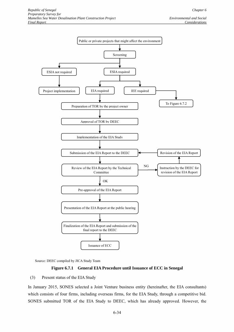
Republic of Senegal Chapter 6
Preparatory Survey for
Mamelles Sea Water Desalination Plant Construction Project Environmental and Social
Final Report Considerations
6-34
Source: DEEC compiled by JICA Study Team
Figure 6.7.1 General EIA Procedure until Issuance of ECC in Senegal
(3) Present status of the EIA Study
In January 2015, SONES selected a Joint Venture business entity (hereinafter, the EIA consultants) which consists of four firms, including overseas firms, for the EIA Study, through a competitive bid. SONES submitted TOR of the EIA Study to DEEC, which has already approved. However, the
Public or private projects that might affect the environment
ESIA not required
Screening
Project implementation IEE required EIA required
ESIA required
Preparation of TOR by the project owner
Approval of TOR by DEEC
Finalization of the EIA Report and submission of the final report to the DEEC
Implementation of the EIA Study
Presentation of the EIA Report at the public hearing
Submission of the EIA Report to the DEEC
OK
NG Review of the EIA Report by the Technical Committee
Pre-approval of the EIA Report
Issuance of ECC
Instruction by the DEEC for revision of the EIA Report
To Figure 6.7.2
Revision of the EIA Report
Republic of Senegal Chapter 6
Preparatory Survey for
Mamelles Sea Water Desalination Plant Construction Project Environmental and Social
Final Report Considerations
6-35
commencement of the EIA Study has been delayed due to the slow budgetary arrangement for the study in the government. The kick-off meeting between SONES and the EIA consultants has just been held on 30th September, 2015.
It is noted that the EIA Study include the study, not only for the Mamelles SWRO Plant, but also the other desalination plant in Grande Cote, which used be called Sendou Seawater Desalination Plant.
(4) Future plan
Based on the discussions during the FF mission (from August to September 2015), ”Minutes of Discussions on Mamelles Sea Water Desalination Project between Ministry of Economy, Finance and Planning of the Government of the Republic of Senegal, and Societe Nationale des Eaux du Senegal and Japan International Cooperation Agency” between JICA, the Ministry of Economy, Finance and Planning (MEFP) and SONES was signed on 4th September in 2015 (hereinafter, “FF mission MD”). According to the FF mission MD, EIA Study will be conducted in the following schedule:
By the end of November 2015, the EIA Consultants will provide “Initial Notes” to SONES. Initial Notes includes results of initial assessment on if the project might have environmental and social issues. SONES shall share “Initial Notes” between JICA promptly after receiving the note.
By the end of February 2016, SONES will prepare Draft EIA Report and submit it to the DEEC. The Draft EIA Report includes environmental management plan and environmental monitoring plan.
The Draft EIA Report will be examined by the Technical Committee of the DEEC.
After a pre-approval by the DEEC, SONES will conduct public hearing. Based on the hearing, SONES will finalize the EIA Report.
By the end of March 2016, SONES will obtain ECC from the DEEC.
EIA Study for ECC acquisition will be completed by March in 2016. However, the EIA Consultant will conduct natural environment to gather information required for detail design until June 2016.
As stated in the above, according to FF mission MD, SONES will prepare “Initial Notes” by the end of November. However, minutes for the kick-off meeting with the EIA Consultants on 30th September states “Initial Notes” will be submitted by 15th December. According to SONES, the delay will not affect ECC acquisition process. Considering the delayed commencement of the EIA Study, the expected schedule is not sure to be followed. It is strongly recommended that SONES should take all necessary and possible measures to implement the EIA Study efficiently. Further delay of the EIA procedure may bring about a delay of the loan agreement expected in March 2016.
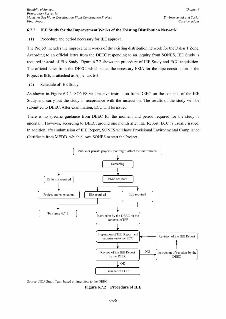
Republic of Senegal Chapter 6
Preparatory Survey for
Mamelles Sea Water Desalination Plant Construction Project Environmental and Social
Final Report Considerations
6-36
6.7.2 IEE Study for the Improvement Works of the Existing Distribution Network
(1) Procedure and period necessary for IEE approval
The Project includes the improvement works of the existing distribution network for the Dakar 1 Zone. According to an official letter from the DEEC responding to an inquiry from SONES, IEE Study is required instead of EIA Study. Figure 6.7.2 shows the procedure of IEE Study and ECC acquisition. The official letter from the DEEC, which states the necessary ESIA for the pipe construction in the Project is IEE, is attached as Appendix 6-3.
(2) Schedule of IEE Study
As shown in Figure 6.7.2, SONES will receive instruction from DEEC on the contents of the IEE Study and carry out the study in accordance with the instruction. The results of the study will be submitted to DEEC. After examination, ECC will be issued.
There is no specific guidance from DEEC for the moment and period required for the study is uncertain. However, according to DEEC, around one month after IEE Report, ECC is usually issued. In addition, after submission of IEE Report, SONES will have Provisional Environmental Compliance Certificate from MEDD, which allows SONES to start the Project.
Source: JICA Study Team based on interview to the DEEC
Figure 6.7.2 Procedure of IEE
Public or private projects that might affect the environment
ESIA not required
Screening
Project implementation IEE requiredEIA required
ESIA requierd
Instruction by the DEEC on the contents of IEE
Preparation of IEE Report and submission to the ECC Revision of the IEE Report
Review of the IEE Report by the DEEC
Instruction of revision by the DEEC
Issuance of ECC
To Figure 6.7.1
OK
NG
Republic of Senegal Chapter 6
Preparatory Survey for
Mamelles Sea Water Desalination Plant Construction Project Environmental and Social
Final Report Considerations
6-37
6.8 Progress and Schedule of Land Acquisition Process
(1) Basic understandings for land acquisition of this Project
As mentioned in Subsection 4.4.2, the total land area to be acquired for the Project to construct the seawater desalination facilities, including the desalination plant and seawater pumping station, is 4.97 ha. In the necessary land, 3.97 ha of the land is located at the flat area halfway up a hill, which is one of the hills known as "Mamelles", and 1.00 ha of land is located on the beach. Out of 4.97 ha, 2.56 ha of land is state-owned, but 2.41 ha of the land, which is the land for the desalination plant, is the property of three private owners. Therefore, land acquisition procedures for the private land are necessary.
(2) Present status of the land acquisition process for the Project
Compensation Evaluation Committee will conduct the land acquisition process. Compensation Evaluation Committee for Mamelles Sea Water Desalination Plant Construction Project was established on 18th February, 2015. The following members consists the committee.
・ Prefect of Dakar Department): chair person
・ Tax Receiver’s Office of Ngor-Almadies: vice chair person
・ Mayor of Dakar City
・ Sub-Prefect of Almadies Arrondissement
・ Mayor of Ouakam Municipality
・ Head of Regional Division of Urbanism
・ Head of Regional Division of Environment and Classified Establishment
・ Head of Land Registry Office of Ngor-Almadies
・ Head of Territorial Gendarmerie
・ Head of Department Service of Social Action
・ Head of Water and Forestry Sector
・ Two representatives of SONES
Figure 6.8.1 shows the procedure of land acquisition. On 3rd June 2015, Directore of Tax and Domain announced the Project to citizens through the national newspaper under directive of the Compensation Evaluation Committee. Until 10th June, stakeholder survey which is called”Commodo et Incommodo” was conducted.
In general, the cut-off date is the commencement day of the census or stakeholder survey of the Project Affected Persons (PAPs) or the stakeholders. Therefore, the cut-off date of the Project will be 3rd June 3, 2015.
Republic of Senegal Chapter 6
Preparatory Survey for
Mamelles Sea Water Desalination Plant Construction Project Environmental and Social
Final Report Considerations
6-38
Based on the stakeholder survey result, Decree No. 2015-1146, Presidential Decree of Expropriation Order of the Land for the Purpose of Public Utility was issued on 3rd August 2015. The expropriation decree specifies that land located in Mamelles Sea Water Desalination Plant Construction Project shall be expropriated within 3 years and implementation of the decree is responsible for MEFP. After the expropriation decree, the Compensation Evaluation Committee will evaluate the lands and existing structures through site investigations to discuss compensation amount. The result of the discussion about the compensation amount will be announced in a presidential decree for transferability. Based on the transferability decree, Compensation Evaluation Committee negotiates with the land owners. Usually, the decrees of the land expropriation and transferability are issues at the same time. To show progress of the land acquisition process to JICA, however, the expropriation decree was issued prior to the transferability decree in the Project.
For the compensation amount, Article 14, No.76-67 (2th July, 1976), stipulates that replacement price shall be paid after negotiation between land owners. However, there is no provision about timing for payment of the compensation. Therefore, Compensation Evaluation Committee and SONES need to conduct appropriate process for compensation before starting the project, in accordance with JICA Environmental Guidelines.
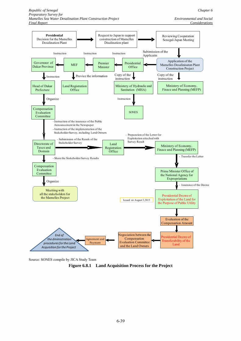
Republic of Senegal Chapter 6
Preparatory Survey for
Mamelles Sea Water Desalination Plant Construction Project Environmental and Social
Final Report Considerations
6-39
Source: SONES compile by JICA Study Team
Figure 6.8.1 Land Acquisition Process for the Project
Ministery of Economy,Finace and Planning (MEFP)
Ministery of Hydraulic andSanitation (MHA)
Head of DakarPrefecture
Land RegistrationOffice
Provice the information
Presidential
Decision for the Mamelles Desalination Plant
Request to Japan to support construction of Mamelles
Disalination plant
Reviewing CooperationSenegal-Japan Meeting
PresidentialOffice
PremierMinister
MEFGovernnor ofDakar Province
Instruction Instruction Instruction Subimission of the Applicatin
Application of the Mamelles Desalinisaton Plant
Construction Project
Presidential Decree of Exploitation of the Land for the Purpose of Public Utility
SONES
Copy of theinstruction
CompensationEvaluationCommittee
Directorate of Taxes andDomain
LandRegistration
Office
Meetiing with all the stakeholders for the Mamelles Project
Prime Minister Office ofthe National Agency for
Expropriations
End of the dmimistration
procedures for the LandAcquisition for the Project
Negociation between the Compensation
Evaluation Committee and the Land Owners
Copy of theinstructionInstruction
Instruction Organize
- Instruction of the issurance of the Public Announcement in the Newspaper
- Instruction of the implementation of theStakeholder Survey, including Land Owners
- Preparation of the Letter for Exploitation attached with Survey Result
- Subimission of the Resuls of the Stakeholder Survey
Ministery of Economy,Finace and Planning (MEFP)
CompensationEvaluationCommittee
- Share the Stakeholder Survey Results
Organize
- Transfer the Letter
Issued on August 3,2015
- Issurance of the Decree
Presidential Decree of Transferability of the
Land
Evaluation of the Compensation Amount
Agreement and Payment
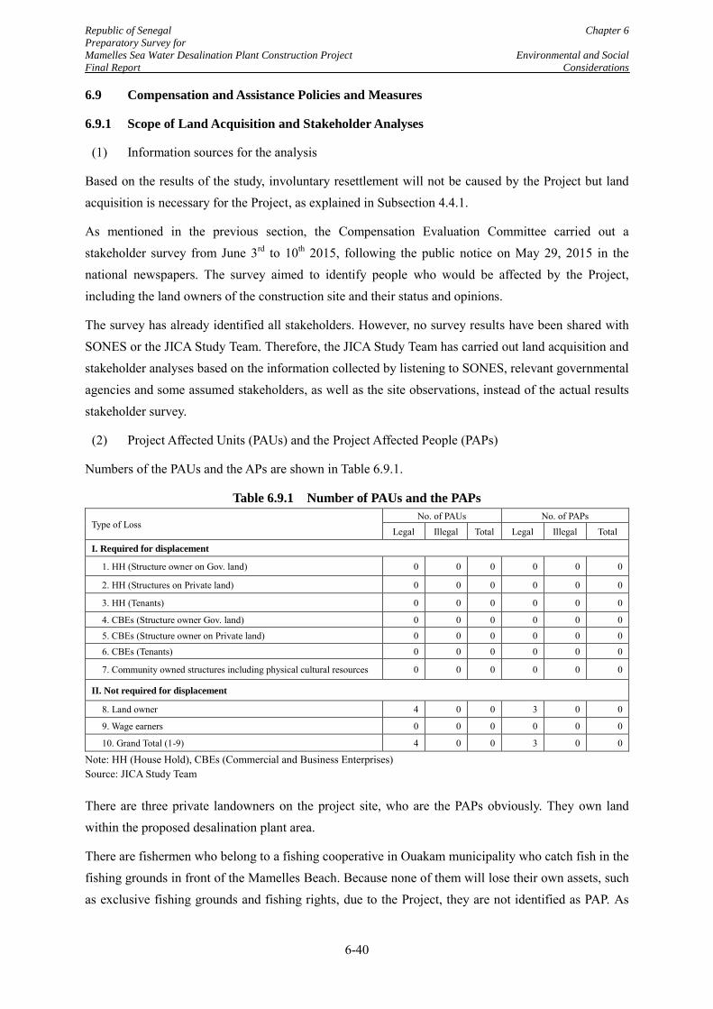
Republic of Senegal Chapter 6
Preparatory Survey for
Mamelles Sea Water Desalination Plant Construction Project Environmental and Social
Final Report Considerations
6-40
6.9 Compensation and Assistance Policies and Measures
6.9.1 Scope of Land Acquisition and Stakeholder Analyses
(1) Information sources for the analysis
Based on the results of the study, involuntary resettlement will not be caused by the Project but land acquisition is necessary for the Project, as explained in Subsection 4.4.1.
As mentioned in the previous section, the Compensation Evaluation Committee carried out a stakeholder survey from June 3rd to 10th 2015, following the public notice on May 29, 2015 in the national newspapers. The survey aimed to identify people who would be affected by the Project, including the land owners of the construction site and their status and opinions.
The survey has already identified all stakeholders. However, no survey results have been shared with SONES or the JICA Study Team. Therefore, the JICA Study Team has carried out land acquisition and stakeholder analyses based on the information collected by listening to SONES, relevant governmental agencies and some assumed stakeholders, as well as the site observations, instead of the actual results stakeholder survey.
(2) Project Affected Units (PAUs) and the Project Affected People (PAPs)
Numbers of the PAUs and the APs are shown in Table 6.9.1.
Table 6.9.1 Number of PAUs and the PAPs
Type of Loss No. of PAUs No. of PAPs
Legal Illegal Total Legal Illegal Total
I. Required for displacement
1. HH (Structure owner on Gov. land) 0 0 0 0 0 0
2. HH (Structures on Private land) 0 0 0 0 0 0
3. HH (Tenants) 0 0 0 0 0 0
4. CBEs (Structure owner Gov. land) 0 0 0 0 0 0 5. CBEs (Structure owner on Private land) 0 0 0 0 0 0 6. CBEs (Tenants) 0 0 0 0 0 0
7. Community owned structures including physical cultural resources 0 0 0 0 0 0
II. Not required for displacement
8. Land owner 4 0 0 3 0 0
9. Wage earners 0 0 0 0 0 0
10. Grand Total (1-9) 4 0 0 3 0 0
Note: HH (House Hold), CBEs (Commercial and Business Enterprises) Source: JICA Study Team
There are three private landowners on the project site, who are the PAPs obviously. They own land within the proposed desalination plant area.
There are fishermen who belong to a fishing cooperative in Ouakam municipality who catch fish in the fishing grounds in front of the Mamelles Beach. Because none of them will lose their own assets, such as exclusive fishing grounds and fishing rights, due to the Project, they are not identified as PAP. As
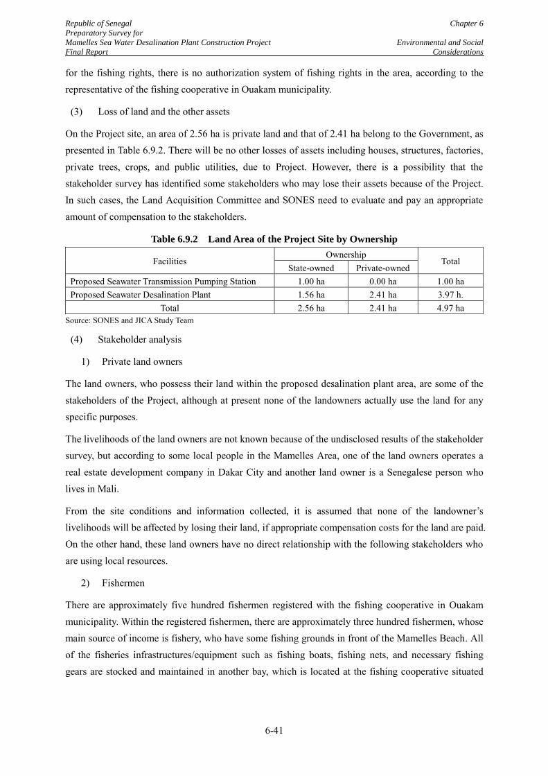
Republic of Senegal Chapter 6
Preparatory Survey for
Mamelles Sea Water Desalination Plant Construction Project Environmental and Social
Final Report Considerations
6-41
for the fishing rights, there is no authorization system of fishing rights in the area, according to the representative of the fishing cooperative in Ouakam municipality.
(3) Loss of land and the other assets
On the Project site, an area of 2.56 ha is private land and that of 2.41 ha belong to the Government, as presented in Table 6.9.2. There will be no other losses of assets including houses, structures, factories, private trees, crops, and public utilities, due to Project. However, there is a possibility that the stakeholder survey has identified some stakeholders who may lose their assets because of the Project. In such cases, the Land Acquisition Committee and SONES need to evaluate and pay an appropriate amount of compensation to the stakeholders.
Table 6.9.2 Land Area of the Project Site by Ownership
Facilities Ownership
Total State-owned Private-owned
Proposed Seawater Transmission Pumping Station 1.00 ha 0.00 ha 1.00 ha Proposed Seawater Desalination Plant 1.56 ha 2.41 ha 3.97 h.
Total 2.56 ha 2.41 ha 4.97 ha Source: SONES and JICA Study Team
(4) Stakeholder analysis
1) Private land owners
The land owners, who possess their land within the proposed desalination plant area, are some of the stakeholders of the Project, although at present none of the landowners actually use the land for any specific purposes.
The livelihoods of the land owners are not known because of the undisclosed results of the stakeholder survey, but according to some local people in the Mamelles Area, one of the land owners operates a real estate development company in Dakar City and another land owner is a Senegalese person who lives in Mali.
From the site conditions and information collected, it is assumed that none of the landowner’s livelihoods will be affected by losing their land, if appropriate compensation costs for the land are paid. On the other hand, these land owners have no direct relationship with the following stakeholders who are using local resources.
2) Fishermen
There are approximately five hundred fishermen registered with the fishing cooperative in Ouakam municipality. Within the registered fishermen, there are approximately three hundred fishermen, whose main source of income is fishery, who have some fishing grounds in front of the Mamelles Beach. All of the fisheries infrastructures/equipment such as fishing boats, fishing nets, and necessary fishing gears are stocked and maintained in another bay, which is located at the fishing cooperative situated
Republic of Senegal Chapter 6
Preparatory Survey for
Mamelles Sea Water Desalination Plant Construction Project Environmental and Social
Final Report Considerations
6-42
just over one km from the beach. A possible conflict of resources use caused by the Project to the fishermen will be about their use of the fishing grounds.
Recently the Ministry of Fisheries has been preparing for setting of ‘fish catch conservation zones’ along the Mamelles coast, including in front of the Mamelles Beach. According to talks with the ministry by the JICA Study Team, the setting of the conservation zone aims to conserve the present fish stock and to promote appropriate fishing methods. The purpose of setting the conservation zone is to prohibit inappropriate fishing methods and to regulate fishing vessels/periods in certain zones to maintain a sustainable fish catch in the area. In addition, the ministry told the JICA Study Team that the ‘fish catch conservation zones’ will not limit any construction work in and around the zone, including that of seawater intake and brine discharge facilities of the Project. On the other hand, application of this new conservation zone may decrease fish catches by the fishermen.
3) Local tourists
It is observed that a good number of local people occasionally visit the Mamelles Beach for recreation purposes. Such local tourists are also considered as one of the stakeholders of the Project. There is a possibility of small-scale conflict caused by the Project on visitors during the construction phase.
On the other hand, the local tourists will not lose their own asset because of the project. Therefore, local tourists are not identified as PAPs, and have no right of entitlement to compensation or assistance.
4) A Sports Association
According to the Senegalese Climbing Association and Nature Sports, the cliff site under the Mamelles Lighthouse is one of their bases for sports activities. The representative of the association insists that the Project will spoil their sports activities.
The JICA Study Team understands that the Project will not affect their activities because it does not change the cliff, and access to the cliff will not be limited, except during the construction phase. In any case, the sports association members are considered as one of the stakeholders of the Project.
On the other hand, the sports association members would not lose an exclusively owned asset because of the project. Therefore, the sports association members are not identified as PAPs, and have no right of entitlement to compensation or assistance by the project.
6.9.2 Compensation Policy and Entitlement Matrix
(1) Compensation policy
In the Project, compensation to the affected landowners will be provided for their private properties. Based on the JICA Environmental and Social Considerations Guidelines, such compensation to landowners should be, as far as possible, the amount of the full replacement cost of the land. The Cut-Off date of the land acquisition will be June 3, 2015 when the stakeholder survey was commenced.
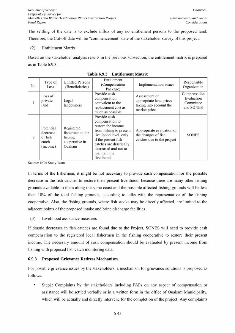
Republic of Senegal Chapter 6
Preparatory Survey for
Mamelles Sea Water Desalination Plant Construction Project Environmental and Social
Final Report Considerations
6-43
The settling of the date is to exclude influx of any no entitlement persons to the proposed land. Therefore, the Cut-off date will be “commencement” date of the stakeholder survey of this project.
(2) Entitlement Matrix
Based on the stakeholder analysis results in the previous subsection, the entitlement matrix is prepared as in Table 6.9.3.
Table 6.9.3 Entitlement Matrix
No. Type of
Loss Entitled Persons (Beneficiaries)
Entitlement (Compensation
Package) Implementation issues Responsible
Organization
1
Loss of private land
Legal landowners
Provide cash compensation equivalent to the replacement cost as much as possible
Assessment of appropriate land prices taking into account the market price
Compensation Evaluation Committee and SONES
2
Potential decrease of fish catch (income)
Registered fishermen to the fishing cooperative in Ouakam
Provide cash compensation to restore the income from fishing to present livelihood level, only if the present fish catches are drastically decreased and not to maintain the livelihood.
Appropriate evaluation of the changes of fish catches due to the project
SONES
Source: JICA Study Team
In terms of the fishermen, it might be not necessary to provide cash compensation for the possible decrease in the fish catches to restore their present livelihood, because there are many other fishing grounds available to them along the same coast and the possible affected fishing grounds will be less than 10% of the total fishing grounds, according to talks with the representative of the fishing cooperative. Also, the fishing grounds, where fish stocks may be directly affected, are limited to the adjacent points of the proposed intake and brine discharge facilities.
(3) Livelihood assistance measures
If drastic decreases in fish catches are found due to the Project, SONES will need to provide cash compensation to the registered local fishermen in the fishing cooperative to restore their present income. The necessary amount of cash compensation should be evaluated by present income from fishing with proposed fish catch monitoring data.
6.9.3 Proposed Grievance Redress Mechanism
For possible grievance issues by the stakeholders, a mechanism for grievance solutions is proposed as follows:
Step1: Complaints by the stakeholders including PAPs on any aspect of compensation or assistance will be settled verbally or in a written form in the office of Ouakam Municipality, which will be actually and directly intervene for the completion of the project. Any complaints
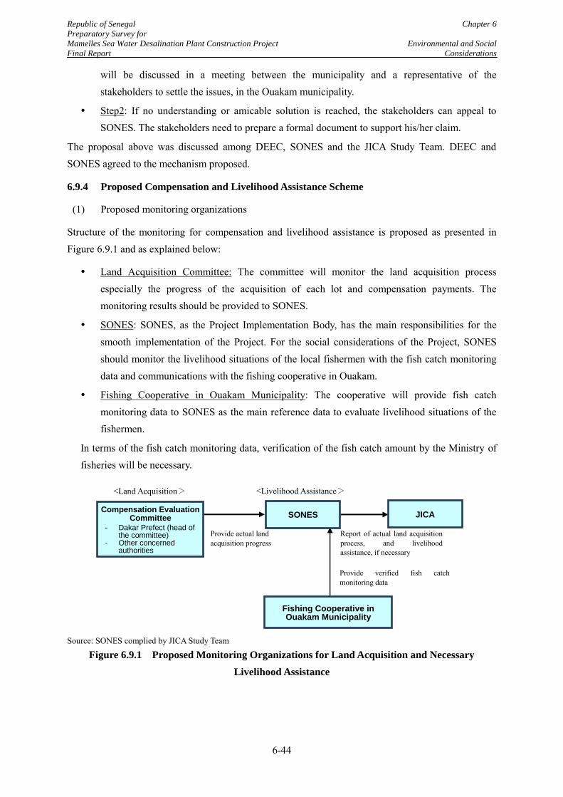
Republic of Senegal Chapter 6
Preparatory Survey for
Mamelles Sea Water Desalination Plant Construction Project Environmental and Social
Final Report Considerations
6-44
will be discussed in a meeting between the municipality and a representative of the stakeholders to settle the issues, in the Ouakam municipality.
Step2: If no understanding or amicable solution is reached, the stakeholders can appeal to SONES. The stakeholders need to prepare a formal document to support his/her claim.
The proposal above was discussed among DEEC, SONES and the JICA Study Team. DEEC and SONES agreed to the mechanism proposed.
6.9.4 Proposed Compensation and Livelihood Assistance Scheme
(1) Proposed monitoring organizations
Structure of the monitoring for compensation and livelihood assistance is proposed as presented in Figure 6.9.1 and as explained below:
Land Acquisition Committee: The committee will monitor the land acquisition process especially the progress of the acquisition of each lot and compensation payments. The monitoring results should be provided to SONES.
SONES: SONES, as the Project Implementation Body, has the main responsibilities for the smooth implementation of the Project. For the social considerations of the Project, SONES should monitor the livelihood situations of the local fishermen with the fish catch monitoring data and communications with the fishing cooperative in Ouakam.
Fishing Cooperative in Ouakam Municipality: The cooperative will provide fish catch monitoring data to SONES as the main reference data to evaluate livelihood situations of the fishermen.
In terms of the fish catch monitoring data, verification of the fish catch amount by the Ministry of fisheries will be necessary.
Source: SONES complied by JICA Study Team
Figure 6.9.1 Proposed Monitoring Organizations for Land Acquisition and Necessary
Livelihood Assistance
Provide actual land acquisition progress
Report of actual land acquisition process, and livelihood assistance, if necessary
<Livelihood Assistance> <Land Acquisition>
JICA
Provide verified fish catch monitoring data
SONES Compensation Evaluation Committee
- Dakar Prefect (head of the committee)
- Other concerned authorities
Fishing Cooperative in Ouakam Municipality
Republic of Senegal Chapter 6
Preparatory Survey for
Mamelles Sea Water Desalination Plant Construction Project Environmental and Social
Final Report Considerations
6-45
(2) Overall costs and funding sources of compensation and assistance.
In the Study, it is estimated that the overall total of land acquisition cost is F.CFA 4,800 million. If it is found that livelihood assistance compensation is necessary for the fishermen, such costs should be additionally paid to restore their income to maintain present livelihood levels. All costs for the compensation and assistance will be paid by SONES.
Republic of Senegal Chapter 6
Preparatory Survey for
Mamelles Sea Water Desalination Plant Construction Project Environmental and Social
Final Report Considerations
6-46
6.10 Construction Permission based on the National Environmental Code
As explained in Sub-section 4.4.1, the Mamelles SWRO Plant is located within 500 m from the historic light house of Mamelles. In compliance with Article L13 of the National Environmental Code, therefore, the Project needs a construction permission from the Ministry of Urban Planning.
Figure 6.10.1 shows the procedure to acquire the construction permission. First, SONES needs to submit the application to the Regional Service of Urban Planning of Dakar. As the application needs to be attached with ECC, the application is possible only after acquisition of the ECC. After the Regional Service of Urban Planning of Dakar hears the opinions of the Ouakam municipality and the local technical services, the application will be transferred to Direction of Urban Planning and Architecture for the final evaluation. After being evaluated, the application will be sent to the Minister of Urban Planning and the permission will be finally signed by the municipality. According to the ministry, duration of the procedure from the submission of the application to the issuance of the permission is usually 30 days.
JICA Study Team views that the construction permission would be issued with no difficult problem considering the project’s high publicness and the fact that the expropriation order has been issued. However, SONES needs to submit the application as soon as possible after the ECC is acquired.
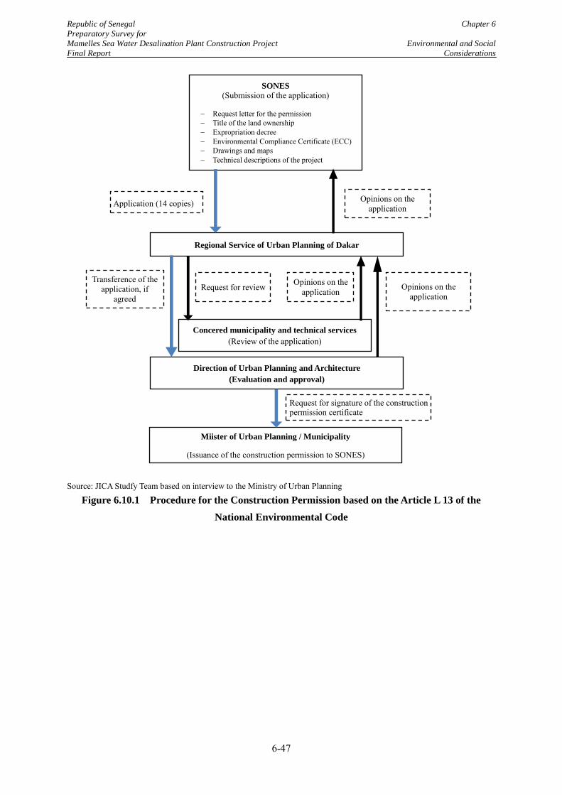
Republic of Senegal Chapter 6
Preparatory Survey for
Mamelles Sea Water Desalination Plant Construction Project Environmental and Social
Final Report Considerations
6-47
Source: JICA Studfy Team based on interview to the Ministry of Urban Planning
Figure 6.10.1 Procedure for the Construction Permission based on the Article L 13 of the
National Environmental Code
SONES (Submission of the application)
Request letter for the permission Title of the land ownership Expropriation decree Environmental Compliance Certificate (ECC) Drawings and maps Technical descriptions of the project
Regional Service of Urban Planning of Dakar
Application (14 copies) Opinions on the application
Concered municipality and technical services
(Review of the application)
Request for review Opinions on the application
Direction of Urban Planning and Architecture
(Evaluation and approval)
Transference of the application, if
agreed
Request for signature of the construction permission certificate
Miister of Urban Planning / Municipality
(Issuance of the construction permission to SONES)
Opinions on the application
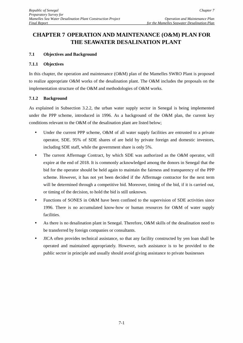
Republic of Senegal Chapter 7 Preparatory Survey for Mamelles Sea Water Desalination Plant Construction Project Operation and Maintenance Plan Final Report for the Mamelles Seawater Desalination Plan
CHAPTER 7 OPERATION AND MAINTENANCE (O&M) PLAN FOR THE SEAWATER DESALINATION PLANT
7.1 Objectives and Background
7.1.1 Objectives
In this chapter, the operation and maintenance (O&M) plan of the Mamelles SWRO Plant is proposed to realize appropriate O&M works of the desalination plant. The O&M includes the proposals on the implementation structure of the O&M and methodologies of O&M works.
7.1.2 Background
As explained in Subsection 3.2.2, the urban water supply sector in Senegal is being implemented under the PPP scheme, introduced in 1996. As a background of the O&M plan, the current key conditions relevant to the O&M of the desalination plant are listed below;
Under the current PPP scheme, O&M of all water supply facilities are entrusted to a private operator, SDE. 95% of SDE shares of are held by private foreign and domestic investors, including SDE staff, while the government share is only 5%.
The current Affermage Contract, by which SDE was authorized as the O&M operator, will expire at the end of 2018. It is commonly acknowledged among the donors in Senegal that the bid for the operator should be held again to maintain the fairness and transparency of the PPP scheme. However, it has not yet been decided if the Affermage contractor for the next term will be determined through a competitive bid. Moreover, timing of the bid, if it is carried out, or timing of the decision, to hold the bid is still unknown.
Functions of SONES in O&M have been confined to the supervision of SDE activities since 1996. There is no accumulated know-how or human resources for O&M of water supply facilities.
As there is no desalination plant in Senegal. Therefore, O&M skills of the desalination need to be transferred by foreign companies or consultants.
JICA often provides technical assistance, so that any facility constructed by yen loan shall be operated and maintained appropriately. However, such assistance is to be provided to the public sector in principle and usually should avoid giving assistance to private businesses
7-1
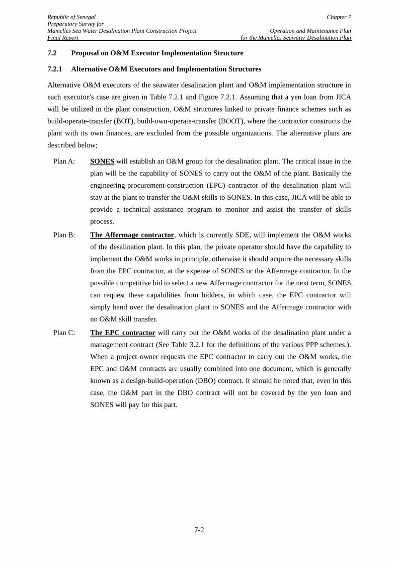
Republic of Senegal Chapter 7 Preparatory Survey for Mamelles Sea Water Desalination Plant Construction Project Operation and Maintenance Plan Final Report for the Mamelles Seawater Desalination Plan
7.2 Proposal on O&M Executor Implementation Structure
7.2.1 Alternative O&M Executors and Implementation Structures
Alternative O&M executors of the seawater desalination plant and O&M implementation structure in each executor’s case are given in Table 7.2.1 and Figure 7.2.1. Assuming that a yen loan from JICA will be utilized in the plant construction, O&M structures linked to private finance schemes such as build-operate-transfer (BOT), build-own-operate-transfer (BOOT), where the contractor constructs the plant with its own finances, are excluded from the possible organizations. The alternative plans are described below;
Plan A: SONES will establish an O&M group for the desalination plant. The critical issue in the plan will be the capability of SONES to carry out the O&M of the plant. Basically the engineering-procurement-construction (EPC) contractor of the desalination plant will stay at the plant to transfer the O&M skills to SONES. In this case, JICA will be able to provide a technical assistance program to monitor and assist the transfer of skills process.
Plan B: The Affermage contractor, which is currently SDE, will implement the O&M works of the desalination plant. In this plan, the private operator should have the capability to implement the O&M works in principle, otherwise it should acquire the necessary skills from the EPC contractor, at the expense of SONES or the Affermage contractor. In the possible competitive bid to select a new Affermage contractor for the next term, SONES, can request these capabilities from bidders, in which case, the EPC contractor will simply hand over the desalination plant to SONES and the Affermage contractor with no O&M skill transfer.
Plan C: The EPC contractor will carry out the O&M works of the desalination plant under a management contract (See Table 3.2.1 for the definitions of the various PPP schemes.). When a project owner requests the EPC contractor to carry out the O&M works, the EPC and O&M contracts are usually combined into one document, which is generally known as a design-build-operation (DBO) contract. It should be noted that, even in this case, the O&M part in the DBO contract will not be covered by the yen loan and SONES will pay for this part.
7-2
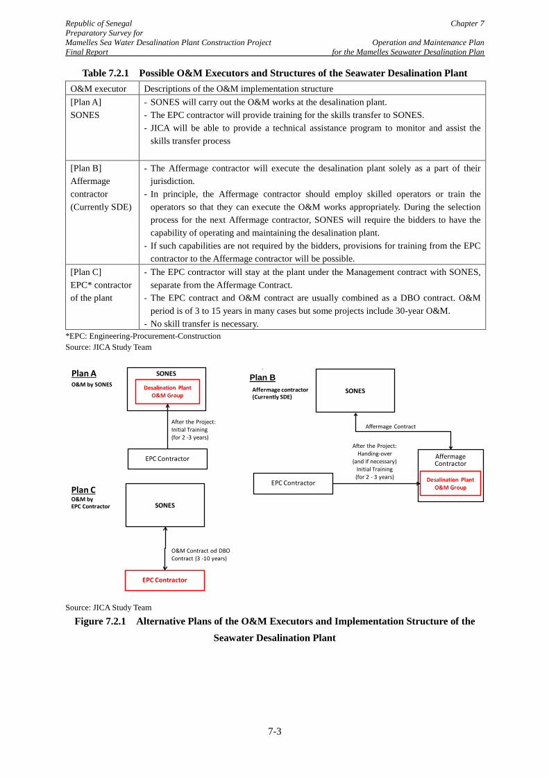
Republic of Senegal Chapter 7 Preparatory Survey for Mamelles Sea Water Desalination Plant Construction Project Operation and Maintenance Plan Final Report for the Mamelles Seawater Desalination Plan
Table 7.2.1 Possible O&M Executors and Structures of the Seawater Desalination Plant O&M executor Descriptions of the O&M implementation structure [Plan A] SONES
- SONES will carry out the O&M works at the desalination plant. - The EPC contractor will provide training for the skills transfer to SONES. - JICA will be able to provide a technical assistance program to monitor and assist the
skills transfer process
[Plan B] Affermage contractor (Currently SDE)
- The Affermage contractor will execute the desalination plant solely as a part of their jurisdiction.
- In principle, the Affermage contractor should employ skilled operators or train the operators so that they can execute the O&M works appropriately. During the selection process for the next Affermage contractor, SONES will require the bidders to have the capability of operating and maintaining the desalination plant.
- If such capabilities are not required by the bidders, provisions for training from the EPC contractor to the Affermage contractor will be possible.
[Plan C] EPC* contractor of the plant
- The EPC contractor will stay at the plant under the Management contract with SONES, separate from the Affermage Contract.
- The EPC contract and O&M contract are usually combined as a DBO contract. O&M period is of 3 to 15 years in many cases but some projects include 30-year O&M.
- No skill transfer is necessary. *EPC: Engineering-Procurement-Construction Source: JICA Study Team
Source: JICA Study Team
Figure 7.2.1 Alternative Plans of the O&M Executors and Implementation Structure of the Seawater Desalination Plant
SONES
Desalination PlantO&M Group
EPC Contractor
After the Project:Initial Training(for 2 -3 years)
Plan AO&M by SONES
Affermage Contractor
Desalination Plant O&M Group
Affermage Contract
B案O&M by Affermage contractor(Currently SDE)
SONES
After the Project:Handing-over
(and if necessary) Initial Training(for 2 - 3 years)
EPC Contractor
O&M Contract od DBO Contract (3 -10 years)
Plan CO&M by EPC Contractor SONES
EPC Contractor
Plan B
7-3
Republic of Senegal Chapter 7 Preparatory Survey for Mamelles Sea Water Desalination Plant Construction Project Operation and Maintenance Plan Final Report for the Mamelles Seawater Desalination Plan
7.2.2 Evaluations of the Alternative O&M Executors and Implementation Structures
Evaluations of the alternative O&M structures by the JICA Study Team are presented in Table 7.2.2.
According to interviews with SONES, SONES do not intend to implement the O&M works by themselves. Such unwillingness for direct involvement in the O&M works is understandable because it is 20 years since they ceased O&M functions and the present O&M structure has achieved good results. Therefore, Plan A is not one of the possible solutions for SONES.
The JICA Study Team recommends Plan B as the viable option, because a satisfactory quality O&M works at the plant is expected and the structure will be conform completely with the present Affermage scheme. In addition, O&M costs (to be paid by SONES) are the lowest of three alternatives, because the Affermage contractor can share the chemicals, materials, equipment, and human sources with the other water treatment plants and pumping stations under their jurisdiction.
On the other hand, Plan C, where the EPC contractor will carry out O&M works at the desalination plant, will not have any problem in respect of the technical aspect. It may mean slightly higher costs of O&M than Plan B but it is expected that the EPC contractor will pay more attention to O&M costs and efficiency in the design and construction of the plant. In addition, quick and flexible correspondences to any accident or trouble at the desalination plant will be expected. These technical advantages will be very attractive to SONES who has no experience of seawater desalination.
Advantages and disadvantages of the alternative O&M executors and implementation structures are described in Table 7.2.2. As Plan B and C have advantages and disadvantages, there is no definite priority between the two alternatives. Considering that there is no accumulated skills and knowledge on O&M of seawater desalination plants in Senegal, however, the JICA Study Team views that Plan C, which has the advantage of high reliability in technical aspects, will be the better plan.
The JICA Study Team also suggests that the O&M structure does not have to be fixed after it is applied. In the next subsection, another alternative for the O&M operator and structure, which will include the possibility of a future shift of the structure, will be proposed so as to present other suitable alternatives to SONES, enabling them to select the best plan
7-4
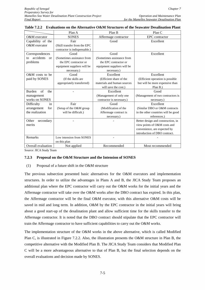
Republic of Senegal Chapter 7 Preparatory Survey for Mamelles Sea Water Desalination Plant Construction Project Operation and Maintenance Plan Final Report for the Mamelles Seawater Desalination Plan
Table 7.2.2 Evaluations on the Alternative O&M Structures of the Seawater Desalination Plant Plan A Plan B Plan C O&M executor SONES Affermage contractor EPC contractor Capability of the O&M executor
Fair (Skill transfer from the EPC contractor is indispensable.)
Good Excellent
Correspondences to accidents or problems
Good (Sometimes assistance from
the EPC contractor or equipment suppliers will be
necessary.)
Good (Sometimes assistance from
the EPC contractor or equipment suppliers will be
necessary.)
Excellent
O&M costs to be paid by SONES
Good (If the skills are
appropriately transferred)
Excellent (Efficient share of the
materials and human sources will save the cost.)
Excellent (Efficient operation is possible
but will be more expensive than Plan B.)
Burden of the management works on SONES
- Excellent (Management of only one contractor is necessary.)
Good (Management of two contractors is
necessary.) Difficulty in arrangement for the realization
Fair (Setup of the O&M group
will be difficult.)
Good (Modification of the
Affermage contract is necessary.)
Excellent (Similar DBO or O&M contracts
in the other countries will be good references.)
Other secondary merits
- - Better design and construction, in view points of O&M costs and convenience, are expected by introduction of DBO contract.
Remarks Low intension from SONES on this plan
- -
Overall evaluation Not applied Recommended Most recommended Source: JICA Study Team
7.2.3 Proposal on the O&M Structure and the Intension of SONES
(1) Proposal of a future shift in the O&M structure
The previous subsection presented basic alternatives for the O&M executors and implementation structures. In order to utilize the advantages in Plans A and B, the JICA Study Team proposes an additional plan where the EPC contractor will carry out the O&M works for the initial years and the Affermage contractor will take over the O&M works after the DBO contract has expired. In this plan, the Affermage contractor will be the final O&M executor, with this alternative O&M costs will be saved in mid and long term. In addition, O&M by the EPC contractor in the initial years will bring about a good start-up of the desalination plant and allow sufficient time for the skills transfer to the Affermage contractor. It is noted that the DBO contract should stipulate that the EPC contractor will train the Affermage contractor to have sufficient capabilities to carry out the O&M works.
The implementation structure of the O&M works in the above alternative, which is called Modified Plan C, is illustrated in Figure 7.2.2. Also, the illustration presents the O&M structure in Plan B, the competitive alternative with the Modified Plan B. The JICA Study Team considers that Modified Plan C will be a more advantageous alternative to that of Plan B, but the final selection depends on the overall evaluations and decision made by SONES.
7-5
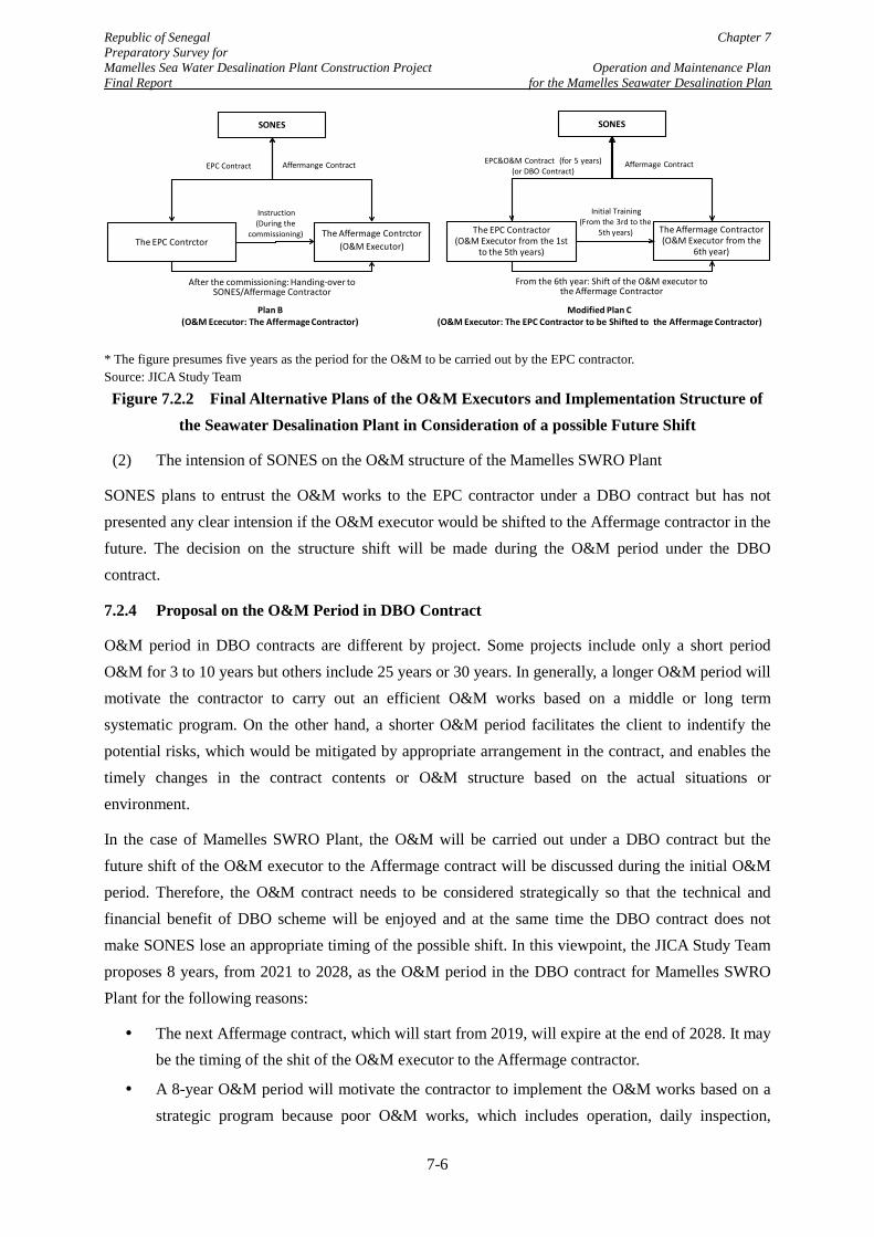
Republic of Senegal Chapter 7 Preparatory Survey for Mamelles Sea Water Desalination Plant Construction Project Operation and Maintenance Plan Final Report for the Mamelles Seawater Desalination Plan
* The figure presumes five years as the period for the O&M to be carried out by the EPC contractor. Source: JICA Study Team
Figure 7.2.2 Final Alternative Plans of the O&M Executors and Implementation Structure of the Seawater Desalination Plant in Consideration of a possible Future Shift
(2) The intension of SONES on the O&M structure of the Mamelles SWRO Plant
SONES plans to entrust the O&M works to the EPC contractor under a DBO contract but has not presented any clear intension if the O&M executor would be shifted to the Affermage contractor in the future. The decision on the structure shift will be made during the O&M period under the DBO contract.
7.2.4 Proposal on the O&M Period in DBO Contract
O&M period in DBO contracts are different by project. Some projects include only a short period O&M for 3 to 10 years but others include 25 years or 30 years. In generally, a longer O&M period will motivate the contractor to carry out an efficient O&M works based on a middle or long term systematic program. On the other hand, a shorter O&M period facilitates the client to indentify the potential risks, which would be mitigated by appropriate arrangement in the contract, and enables the timely changes in the contract contents or O&M structure based on the actual situations or environment.
In the case of Mamelles SWRO Plant, the O&M will be carried out under a DBO contract but the future shift of the O&M executor to the Affermage contract will be discussed during the initial O&M period. Therefore, the O&M contract needs to be considered strategically so that the technical and financial benefit of DBO scheme will be enjoyed and at the same time the DBO contract does not make SONES lose an appropriate timing of the possible shift. In this viewpoint, the JICA Study Team proposes 8 years, from 2021 to 2028, as the O&M period in the DBO contract for Mamelles SWRO Plant for the following reasons:
The next Affermage contract, which will start from 2019, will expire at the end of 2028. It may be the timing of the shit of the O&M executor to the Affermage contractor.
A 8-year O&M period will motivate the contractor to implement the O&M works based on a strategic program because poor O&M works, which includes operation, daily inspection,
The Affermage Contractor(O&M Executor from the
6th year)
SONES
The EPC Contractor(O&M Executor from the 1st
to the 5th years)
Initial Training(From the 3rd to the
5th years)
EPC&O&M Contract (for 5 years)(or DBO Contract)
Affermage Contract
From the 6th year: Shift of the O&M executor to the Affermage Contractor
The Affermage Contrctor(O&M Executor)
SONES
The EPC Contrctor
Instruction(During the
commissioning)
EPC Contract Affermange Contract
After the commissioning: Handing-over to SONES/Affermage Contractor
Plan B(O&M Ececutor: The Affermage Contractor)
Modified Plan C(O&M Executor: The EPC Contractor to be Shifted to the Affermage Contractor)
7-6
Republic of Senegal Chapter 7 Preparatory Survey for Mamelles Sea Water Desalination Plant Construction Project Operation and Maintenance Plan Final Report for the Mamelles Seawater Desalination Plan
replacement of consumables, etc., will gradually bring about visible problems in the equipment in the plant after 5 years.
Although it depends on the design of the contractor, life span of the RO membrane will be 5 to 7 years. Therefore, 8 years will be a reasonable duration to cover one cycle period of O&M works of a SWRO plant
In the bid to procure the DBO contractor, the financial evaluation may be done on the lifecycle cost, which includes initial and running costs. O&M works for 8 years will surely cover the initial cycle of the O&M works and the responsibility for the O&M cost proposed in the bid will be clear.
7-7
Republic of Senegal Chapter 7 Preparatory Survey for Mamelles Sea Water Desalination Plant Construction Project Operation and Maintenance Plan Final Report for the Mamelles Seawater Desalination Plan
7.3 Proposal on O&M Methodologies
7.3.1 Types of the O&M Contract and Possible Supervision Works by SONES
As explained in Section 7.2, the O&M of the Mamelles SWRO Plant will be entrusted to a private O&M executor, who will be the Affermage contractor or the EPC contractor. The O&M executer will be responsible for the appropriate execution of the O&M works at the plant. On the other hand, SONES should manage or supervise the O&M works by the O&M executor and, if necessary, should give instructions for improvement.
Supervision works of SONES and responsibilities of the O&M executor depends on the stipulations in the O&M contract. Generally, the O&M contract has two different types which are a specification order and a performance order. Outlines of the two types of the O&M contract and possible supervision works by SONES are described in Table 7.3.1. In the two O&M contract types, the performance order is suitable for the Mamelles SWRO Plant, as SONES, which has no experience of the O&M of a desalination plant and cannot prepare valid specifications of O&M works of a desalination plant. The performance contract has another advantage, it is relatively similar to the Affermage structure and the ongoing O&M scheme, because of this future integration of the O&M contract with the Affermage contract would be easier.
In case of performance order, the supervision works of the client have a wide variety by contract. For example, if all cost items are defined as the fixed fee, supervision work of the client will be only to evaluate if the required performance in the contract is satisfied. On the other hand, if variable fee is introduced, the client needs to regularly verify if the actual consumptions of the variable cost items such as electricity and chemical are in appropriate ranges.
In O&M of seawater desalination plant, unfavourable change in the seawater quality, which is out of control of the O&M executor, may incur unexpected hikes in electricity cost and chemical cost. In particular, electricity, whose cost occupies more than a half of the total O&M cost, is usually defined as a variable fee as the O&M executor is unwilling to take the risk of such unexpected hike in the electricity cost. In addition, daily maintenance and replacement of the consumable equipment or materials are usually included in the fixed fee. However, when an unusual and unexpected repair or replacement work turns out necessary, the client needs to discuss with the O&M executor on the reasons and responsibility of such event. Therefore, the client should have sufficient knowledge on O&M of the seawater desalination plant to appropriately supervise the O&M work technically and financially.
7-8
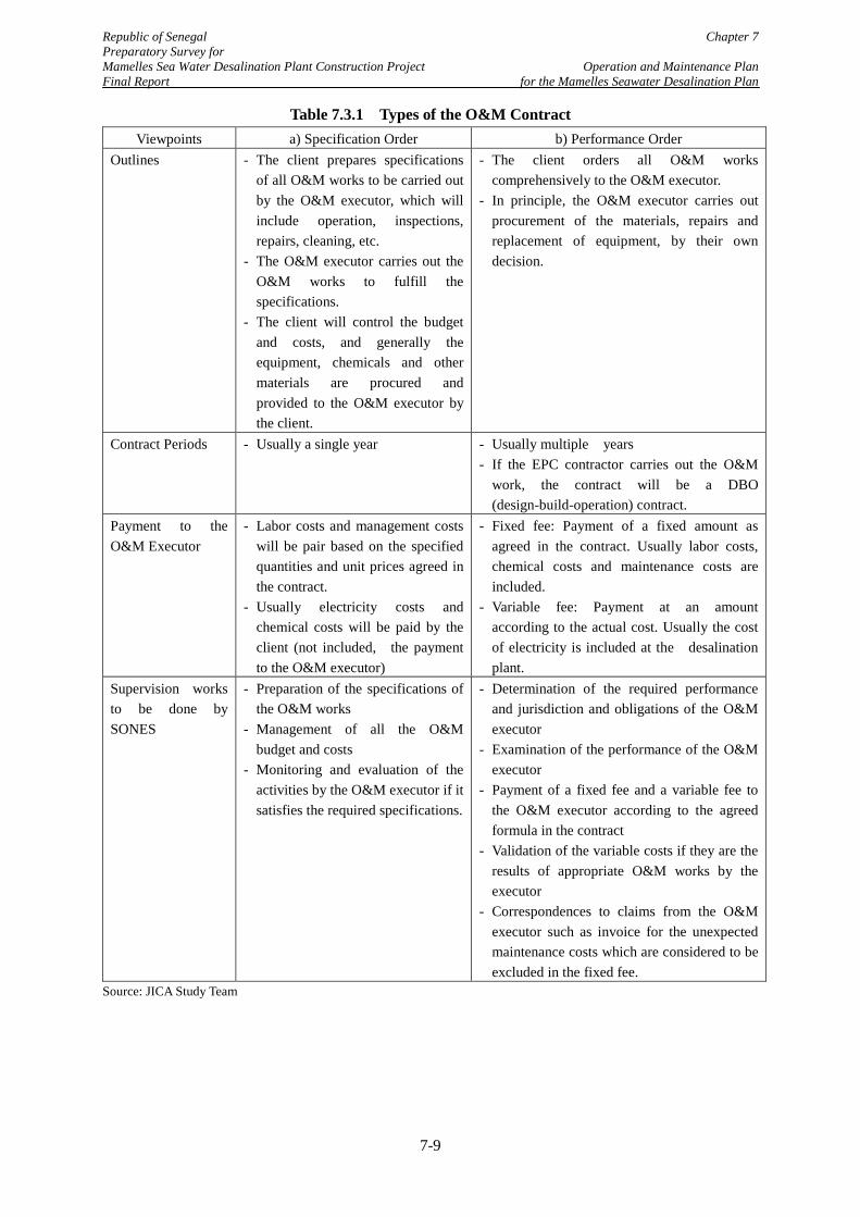
Republic of Senegal Chapter 7 Preparatory Survey for Mamelles Sea Water Desalination Plant Construction Project Operation and Maintenance Plan Final Report for the Mamelles Seawater Desalination Plan
Table 7.3.1 Types of the O&M Contract Viewpoints a) Specification Order b) Performance Order
Outlines - The client prepares specifications of all O&M works to be carried out by the O&M executor, which will include operation, inspections, repairs, cleaning, etc.
- The O&M executor carries out the O&M works to fulfill the specifications.
- The client will control the budget and costs, and generally the equipment, chemicals and other materials are procured and provided to the O&M executor by the client.
- The client orders all O&M works comprehensively to the O&M executor.
- In principle, the O&M executor carries out procurement of the materials, repairs and replacement of equipment, by their own decision.
Contract Periods - Usually a single year - Usually multiple years - If the EPC contractor carries out the O&M
work, the contract will be a DBO (design-build-operation) contract.
Payment to the O&M Executor
- Labor costs and management costs will be pair based on the specified quantities and unit prices agreed in the contract.
- Usually electricity costs and chemical costs will be paid by the client (not included, the payment to the O&M executor)
- Fixed fee: Payment of a fixed amount as agreed in the contract. Usually labor costs, chemical costs and maintenance costs are included.
- Variable fee: Payment at an amount according to the actual cost. Usually the cost of electricity is included at the desalination plant.
Supervision works to be done by SONES
- Preparation of the specifications of the O&M works
- Management of all the O&M budget and costs
- Monitoring and evaluation of the activities by the O&M executor if it satisfies the required specifications.
- Determination of the required performance and jurisdiction and obligations of the O&M executor
- Examination of the performance of the O&M executor
- Payment of a fixed fee and a variable fee to the O&M executor according to the agreed formula in the contract
- Validation of the variable costs if they are the results of appropriate O&M works by the executor
- Correspondences to claims from the O&M executor such as invoice for the unexpected maintenance costs which are considered to be excluded in the fixed fee.
Source: JICA Study Team
7-9
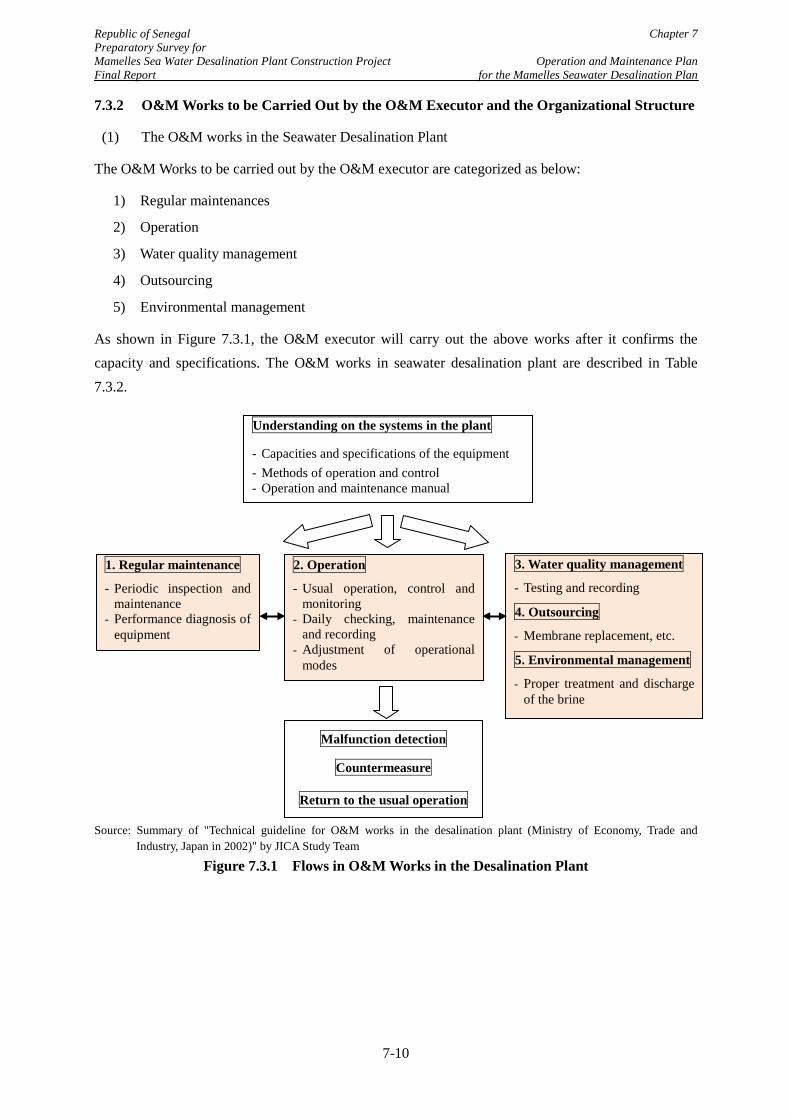
Republic of Senegal Chapter 7 Preparatory Survey for Mamelles Sea Water Desalination Plant Construction Project Operation and Maintenance Plan Final Report for the Mamelles Seawater Desalination Plan
7.3.2 O&M Works to be Carried Out by the O&M Executor and the Organizational Structure
(1) The O&M works in the Seawater Desalination Plant
The O&M Works to be carried out by the O&M executor are categorized as below:
1) Regular maintenances
2) Operation
3) Water quality management
4) Outsourcing
5) Environmental management
As shown in Figure 7.3.1, the O&M executor will carry out the above works after it confirms the capacity and specifications. The O&M works in seawater desalination plant are described in Table 7.3.2.
Source: Summary of "Technical guideline for O&M works in the desalination plant (Ministry of Economy, Trade and
Industry, Japan in 2002)" by JICA Study Team
Figure 7.3.1 Flows in O&M Works in the Desalination Plant
1. Regular maintenance
- Periodic inspection and maintenance
- Performance diagnosis of equipment
2. Operation
- Usual operation, control and monitoring
- Daily checking, maintenance and recording
- Adjustment of operational modes
3. Water quality management
- Testing and recording
4. Outsourcing
- Membrane replacement, etc.
5. Environmental management
- Proper treatment and discharge of the brine
Understanding on the systems in the plant
- Capacities and specifications of the equipment - Methods of operation and control - Operation and maintenance manual
Malfunction detection
Countermeasure
Return to the usual operation
7-10
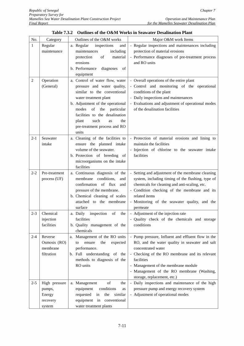
Republic of Senegal Chapter 7 Preparatory Survey for Mamelles Sea Water Desalination Plant Construction Project Operation and Maintenance Plan Final Report for the Mamelles Seawater Desalination Plan
Table 7.3.2 Outlines of the O&M Works in Seawater Desalination Plant No. Category Outlines of the O&M works Major O&M work Items 1 Regular
maintenance a. Regular inspections and
maintenances including protection of material erosions
b. Performance diagnoses of equipment
- Regular inspections and maintenances including protection of material erosions
- Performance diagnoses of pre-treatment process and RO units
2 Operation (General)
a. Control of water flow, water pressure and water quality, similar to the conventional water treatment plant
b. Adjustment of the operational modes of the particular facilities to the desalination plant such as the pre-treatment process and RO units
- Overall operations of the entire plant - Control and monitoring of the operational
conditions of the plant - Daily inspections and maintenances - Evaluations and adjustment of operational modes
of the desalination facilities
2-1 Seawater intake
a. Cleaning of the facilities to ensure the planned intake volume of the seawater.
b. Protection of breeding of microorganisms on the intake facilities
- Protection of material erosions and lining to maintain the facilities
- Injection of chlorine to the seawater intake facilities
2-2 Pre-treatment process (UF)
a. Continuous diagnosis of the membrane conditions, and confirmation of flux and pressure of the membrane.
b. Chemical cleaning of scales attached to the membrane surface
- Setting and adjustment of the membrane cleaning system, including timing of the flushing, type of chemicals for cleaning and anti-scaling, etc.
- Condition checking of the membrane and its related items
- Monitoring of the seawater quality, and the permeate
2-3 Chemical injection facilities
a. Daily inspection of the facilities
b. Quality management of the chemicals
- Adjustment of the injection rate - Quality check of the chemicals and storage
conditions
2-4 Reverse Osmosis (RO) membrane filtration
a. Management of the RO units to ensure the expected performance.
b. Full understanding of the methods to diagnosis of the RO units
- Pump pressure, Influent and effluent flow in the RO, and the water quality in seawater and salt concentrated water
- Checking of the RO membrane and its relevant facilities
- Management of the membrane module - Management of the RO membrane (Washing,
storage, replacement, etc.) 2-5 High pressure
pumps, Energy recovery system
a. Management of the equipment conditions as requested in the similar equipment in conventional water treatment plants
- Daily inspections and maintenance of the high pressure pump and energy recovery system
- Adjustment of operational modes
7-11
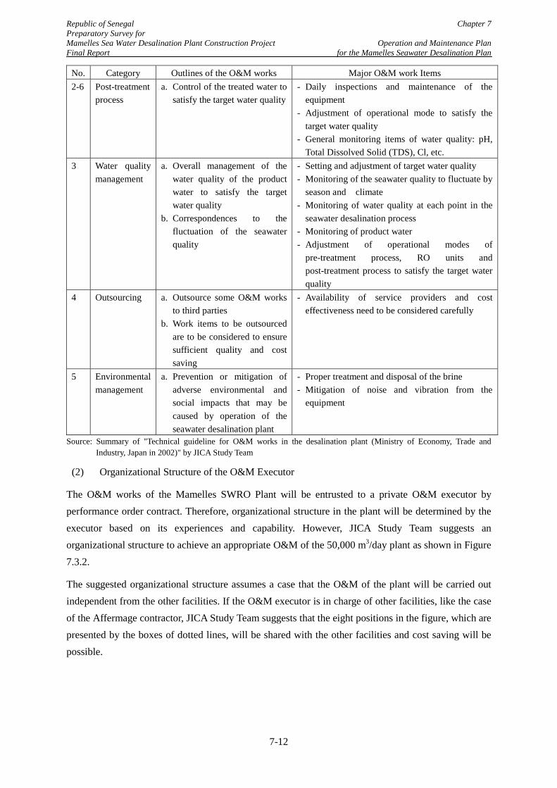
Republic of Senegal Chapter 7 Preparatory Survey for Mamelles Sea Water Desalination Plant Construction Project Operation and Maintenance Plan Final Report for the Mamelles Seawater Desalination Plan
No. Category Outlines of the O&M works Major O&M work Items 2-6 Post-treatment
process a. Control of the treated water to
satisfy the target water quality
- Daily inspections and maintenance of the equipment
- Adjustment of operational mode to satisfy the target water quality
- General monitoring items of water quality: pH, Total Dissolved Solid (TDS), Cl, etc.
3 Water quality management
a. Overall management of the water quality of the product water to satisfy the target water quality
b. Correspondences to the fluctuation of the seawater quality
- Setting and adjustment of target water quality - Monitoring of the seawater quality to fluctuate by
season and climate - Monitoring of water quality at each point in the
seawater desalination process - Monitoring of product water - Adjustment of operational modes of
pre-treatment process, RO units and post-treatment process to satisfy the target water quality
4 Outsourcing a. Outsource some O&M works to third parties
b. Work items to be outsourced are to be considered to ensure sufficient quality and cost saving
- Availability of service providers and cost effectiveness need to be considered carefully
5 Environmental management
a. Prevention or mitigation of adverse environmental and social impacts that may be caused by operation of the seawater desalination plant
- Proper treatment and disposal of the brine - Mitigation of noise and vibration from the
equipment
Source: Summary of "Technical guideline for O&M works in the desalination plant (Ministry of Economy, Trade and Industry, Japan in 2002)" by JICA Study Team
(2) Organizational Structure of the O&M Executor
The O&M works of the Mamelles SWRO Plant will be entrusted to a private O&M executor by performance order contract. Therefore, organizational structure in the plant will be determined by the executor based on its experiences and capability. However, JICA Study Team suggests an organizational structure to achieve an appropriate O&M of the 50,000 m3/day plant as shown in Figure 7.3.2.
The suggested organizational structure assumes a case that the O&M of the plant will be carried out independent from the other facilities. If the O&M executor is in charge of other facilities, like the case of the Affermage contractor, JICA Study Team suggests that the eight positions in the figure, which are presented by the boxes of dotted lines, will be shared with the other facilities and cost saving will be possible.
7-12
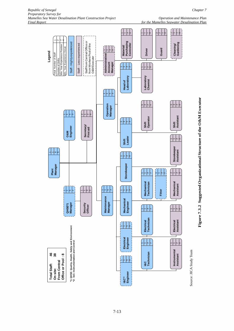
Republic of Senegal Chapter 7 Preparatory Survey for Mamelles Sea Water Desalination Plant Construction Project Operation and Maintenance Plan Final Report for the Mamelles Seawater Desalination Plan
Adm
inis
trat
ive/
Acc
ount
Man
ager
1 1 3 0
Mai
nten
ance
M
anag
er
1 1 5 3
Plan
tM
anag
er
1 1 8 5
QH
SE*1
Man
ager
1 1 5 2
O&
M
Engi
neer
1 1 5 3
Secu
rity
Off
icer
1 1 3 0
Ope
ratio
n M
anag
er
1 1 5 3
I&C
*2
Engi
neer
1 1 5 0
Elec
tric
alEn
gine
er
1 1 5 0St
orek
eepe
r1 1 3 0
Mec
hani
cal
Engi
neer
1 1 5 3
Hea
d of
Labo
rato
ry
1 1 3 2
Shift
Le
ader
5 3 5 3
Mec
hani
cal
Tech
nici
an
1 1 3 2
Elec
tric
alTe
chni
cian
1 1 3 2
I&C
Tech
nici
an
1 1 3 2
Fitt
er3 1 3 2
Elec
tric
al
Ass
ista
nt
1 1 2 0
Inst
rum
enta
lA
ssis
tant
1 1 2 0
Shift
Ope
rato
r
5 3 2 0
Labo
rato
ry
Che
mis
t
1 1 2 0
Secr
etar
y/Fi
rst a
id
2 1 2 0
Mat
eria
l/Pu
rcha
sing
C
ontr
olle
r
1 1 3 0
Driv
er
1 1 1 0
Gua
rd2 2 1 0
1 2 3 4
Tota
l N
umbe
r of
Sta
ffN
umbe
r of S
hift
s
Min
. Yea
r Exp
erie
nce
Des
al.
Lege
nd
Staf
f -H
ighl
y exp
erie
nced
Staf
f -Le
ss e
xper
ienc
ed
Min
. Yea
r Exp
erie
nce
Pos
ition
Tota
l Sta
ff:
4
6O
n si
te:
3
8Fr
om C
entra
l O
ffice
or P
ool :
8
Cle
anin
g/G
arde
ning
1 1 1 0
Mec
hani
cal
Ass
ista
nt
2 1 2 0
Stor
ekee
per
Ass
ista
nt
1 1 2 0
Shift
Ass
ista
nt
5 3 2 0
Staf
f fro
m C
entra
l Offi
ce o
r fro
m W
orke
rs P
ool o
f the
O
&M E
xecu
ter
*1: Q
HSE
: Qua
lity,
Hea
lth, S
afet
y an
d En
viro
nmen
t*2
: I&
C: I
nstr
umen
tatio
n an
d C
ontr
ol
Sour
ce: J
ICA
Stu
dy T
eam
Fig
ure
7.3.
2 S
ugge
sted
Org
aniz
atio
nal S
truc
ture
of t
he O
&M
Exe
cuto
r
7-13
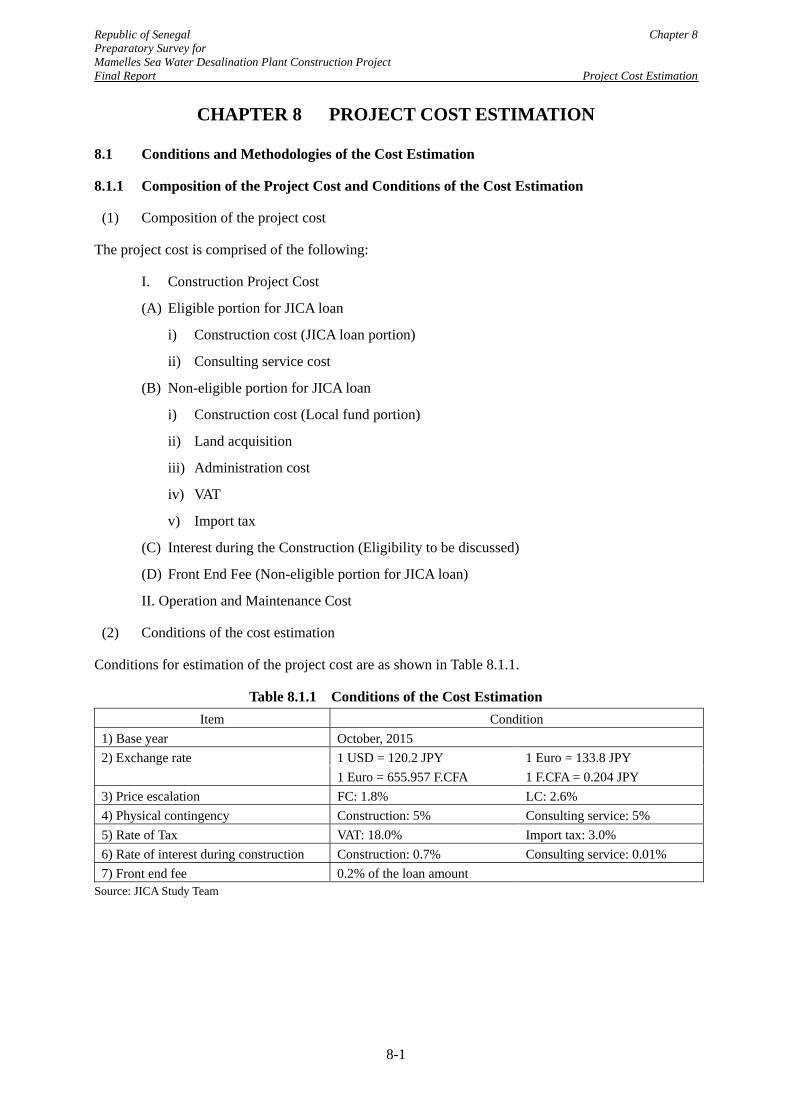
Republic of Senegal Chapter 8 Preparatory Survey for Mamelles Sea Water Desalination Plant Construction Project Final Report Project Cost Estimation
8-1
CHAPTER 8 PROJECT COST ESTIMATION
8.1 Conditions and Methodologies of the Cost Estimation
8.1.1 Composition of the Project Cost and Conditions of the Cost Estimation
(1) Composition of the project cost
The project cost is comprised of the following:
I. Construction Project Cost
(A) Eligible portion for JICA loan
i) Construction cost (JICA loan portion)
ii) Consulting service cost
(B) Non-eligible portion for JICA loan
i) Construction cost (Local fund portion)
ii) Land acquisition
iii) Administration cost
iv) VAT
v) Import tax
(C) Interest during the Construction (Eligibility to be discussed)
(D) Front End Fee (Non-eligible portion for JICA loan)
II. Operation and Maintenance Cost
(2) Conditions of the cost estimation
Conditions for estimation of the project cost are as shown in Table 8.1.1.
Table 8.1.1 Conditions of the Cost Estimation Item Condition
1) Base year October, 2015 2) Exchange rate 1 USD = 120.2 JPY 1 Euro = 133.8 JPY 1 Euro = 655.957 F.CFA 1 F.CFA = 0.204 JPY 3) Price escalation FC: 1.8% LC: 2.6% 4) Physical contingency Construction: 5% Consulting service: 5% 5) Rate of Tax VAT: 18.0% Import tax: 3.0% 6) Rate of interest during construction Construction: 0.7% Consulting service: 0.01% 7) Front end fee 0.2% of the loan amount
Source: JICA Study Team
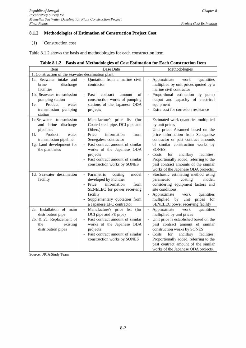
Republic of Senegal Chapter 8 Preparatory Survey for Mamelles Sea Water Desalination Plant Construction Project Final Report Project Cost Estimation
8-2
8.1.2 Methodologies of Estimation of Construction Project Cost
(1) Construction cost
Table 8.1.2 shows the basis and methodologies for each construction item.
Table 8.1.2 Basis and Methodologies of Cost Estimation for Each Construction Item Item Base Data Methodologies
1. Construction of the seawater desalination plant 1a. Seawater intake and
brine discharge facilities
- Quotation from a marine civil contractor
- Approximate work quantities multiplied by unit prices quoted by a marine civil contractor
1b. Seawater transmission pumping station
1e. Product water transmission pumping station
- Past contract amount of construction works of pumping stations of the Japanese ODA projects
- Proportional estimation by pump output and capacity of electrical equipment
- Extra cost for corrosion resistance
1c.Seawater transmission and brine discharge pipelines
1f. Product water transmission pipeline
1g. Land development for the plant sites
- Manufacture's price list (for Coated steel pipe, DCI pipe and Others)
- Price information from Senegalese contractor
- Past contract amount of similar works of the Japanese ODA projects
- Past contract amount of similar construction works by SONES
- Estimated work quantities multiplied by unit prices
- Unit price: Assumed based on the price information from Senegalese contractor or past contract amounts of similar construction works by SONES
- Costs for ancillary facilities: Proportionally added, referring to the past contract amounts of the similar works of the Japanese ODA projects.
1d. Seawater desalination facility
- Parametric costing model developed by Fichtner
- Price information from SENELEC for power receiving facility
- Supplementary quotation from a Japanese EPC contractor
- Stochastic estimating method using parametric costing model, considering equipment factors and site conditions.
- Approximate work quantities multiplied by unit prices for SENELEC power receiving facility
2a. Installation of main distribution pipe
2b. & 2c. Replacement of the existing distribution pipes
- Manufacture's price list (for DCI pipe and PE pipe)
- Past contract amount of similar works of the Japanese ODA projects
- Past contract amount of similar construction works by SONES
- Approximate work quantities multiplied by unit prices
- Unit price is established based on the past contract amount of similar construction works by SONES
- Costs for ancillary facilities: Proportionally added, referring to the past contract amount of the similar works of the Japanese ODA projects.
Source: JICA Study Team
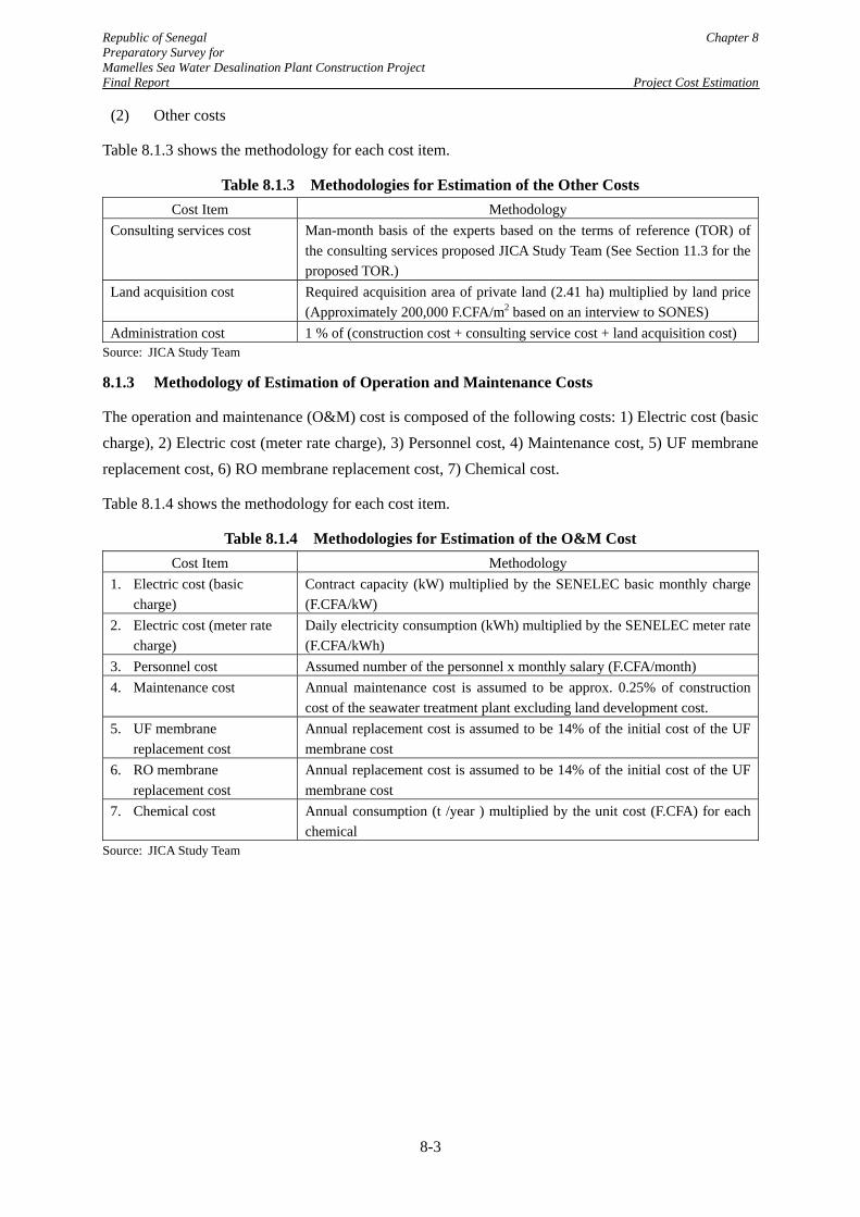
Republic of Senegal Chapter 8 Preparatory Survey for Mamelles Sea Water Desalination Plant Construction Project Final Report Project Cost Estimation
8-3
(2) Other costs
Table 8.1.3 shows the methodology for each cost item.
Table 8.1.3 Methodologies for Estimation of the Other Costs Cost Item Methodology
Consulting services cost Man-month basis of the experts based on the terms of reference (TOR) of the consulting services proposed JICA Study Team (See Section 11.3 for the proposed TOR.)
Land acquisition cost Required acquisition area of private land (2.41 ha) multiplied by land price (Approximately 200,000 F.CFA/m2 based on an interview to SONES)
Administration cost 1 % of (construction cost + consulting service cost + land acquisition cost) Source: JICA Study Team
8.1.3 Methodology of Estimation of Operation and Maintenance Costs
The operation and maintenance (O&M) cost is composed of the following costs: 1) Electric cost (basic charge), 2) Electric cost (meter rate charge), 3) Personnel cost, 4) Maintenance cost, 5) UF membrane replacement cost, 6) RO membrane replacement cost, 7) Chemical cost.
Table 8.1.4 shows the methodology for each cost item.
Table 8.1.4 Methodologies for Estimation of the O&M Cost Cost Item Methodology
1. Electric cost (basic charge)
Contract capacity (kW) multiplied by the SENELEC basic monthly charge (F.CFA/kW)
2. Electric cost (meter rate charge)
Daily electricity consumption (kWh) multiplied by the SENELEC meter rate (F.CFA/kWh)
3. Personnel cost Assumed number of the personnel x monthly salary (F.CFA/month) 4. Maintenance cost Annual maintenance cost is assumed to be approx. 0.25% of construction
cost of the seawater treatment plant excluding land development cost. 5. UF membrane
replacement cost Annual replacement cost is assumed to be 14% of the initial cost of the UF membrane cost
6. RO membrane replacement cost
Annual replacement cost is assumed to be 14% of the initial cost of the UF membrane cost
7. Chemical cost Annual consumption (t /year ) multiplied by the unit cost (F.CFA) for each chemical
Source: JICA Study Team
Republic of Senegal Chapter 8 Preparatory Survey for Mamelles Sea Water Desalination Plant Construction Project Final Report Project Cost Estimation
8-4
8.2 Cost Estimation
8.2.1 Construction Project Cost
(1) Construction cost
Summary of the estimated construction costs is presented in Table 8.2.1. Breakdown of the cost is shown in Appendix 8-1.
(2) Total project cost and disbursement schedule
Summary of the overall project cost and the annual disbursement plan are presented in Tables 8.2.2 and 8.2.3. Bases of the cost estimation, which include the cost breakdown and schedule of the consulting services, are shown in Appendix 8-2.Further, costs estimated for the consulting services and dispute board cost are shown in Appendix 8-3 and 8-4 respectively.
Cost items are separated into the eligible item of the yen loan and the non-eligible items (See Section 9.1 for the definition of the eligible and non-eligible items.). In the project cost estimation, the yen loan is assumed to cover the all eligible items except for the interest during construction.
Republic of Senegal Chapter 8
Preparatory Survey for
Mamelles Sea Water Desalination Plant Construction Project
Final Report Project Cost Estimation
8-5
Table 8.2.1 Summary of the Construction Cost in the Project
Item Amount (Yen) Amount (F.CFA)
1. Construction of the seawater desalination plant
1a. Seawater intake and brine discharge facilities 1,371,560,000 6,723,332,000
(1) Material Procurement 252,068,000 1,235,627,000 (2) Transportation 22,800,000 111,765,000 (3) Offshore civil works 170,880,000 837,647,000 (4) Pipe Installation Works 170,958,000 838,029,000 (5) Onshore Civil Works 204,000,000 1,000,000,000 (6) Onshore Pipe Installation Works 3,600,000 17,647,000 (7) Temporary Works 139,200,000 682,353,000 (8) Site Management 184,320,000 903,529,000 (9) Engineering 18,000,000 88,235,000 (10) General Expense 205,734,000 1,008,500,000 1b. Seawater transmission pumping station 585,846,000 2,871,795,000
(1) Mechanical works 328,844,500 1,611,983,000 (2) Electrical Works 109,021,740 534,420,000 (3) Civil Works 147,980,000 725,392,000 1c. Seawater transmission and brine discharge pipeline 394,777,000 1,935,181,000
(1) Pipe material 316,594,000 1,551,931,000 (2) Installation 78,182,934 383,250,000 1d. Seawater desalination facility 8,443,000,000 41,387,255,000
(1) Mechanical works 1) Pre-treatment section 1,180,000,000 5,784,314,000 2) Reverse osmosis section 2,712,000,000 13,294,118,000 3) Post treatment section 685,000,000 3,357,843,000 4) Waste water treatment plant 231,000,000 1,132,353,000 Sub-total 4,808,000,000 23,568,628,000
(2) Electrical works 1,039,000,000 5,093,137,000 (3) I&C works 346,000,000 1,696,078,000 (4) Auxiliary systems 462,000,000 2,264,706,000 (5) Civil works 1,154,000,000 5,656,863,000 (6) SENELEC Power Receiving 634,000,000 3,107,843,000 1e. Product water transmission pumping station 50,182,000 245,989,000
(1) Mechanical works 27,464,000 134,627,000 (2) Electrical Works 13,655,000 66,936,000 (3) Civil Works 9,063,000 44,426,000 1f. Product water transmission pipeline 65,880,000 322,941,000
(1) Pipe material 51,702,000 253,441,000 (2) Installation 14,178,000 69,500,000 1g. Land development for the plant sites 278,004,000 1,362,765,000
(1) Temporary Work 20,593,000 100,946,000 (2) Earth Work 136,212,000 667,706,000 (3) Slope Protection and Retaining Wall 56,989,000 279,358,000 (4) Road work 51,952,000 254,667,000 (5) Miscellaneous Work 12,258,000 60,088,000 Grand total of 1 11,189,249,000 54,849,258,000
2. Improvement works of the existing distribution network
2a. Installation of main distribution pipes (D700, L=13.5km ) 1,317,191,000 6,456,819,000
(1) Pipe material 890,873,000 4,367,025,000 (2) Installation 363,595,000 1,782,328,000 (3) Miscellaneous 62,723,000 307,466,000 2b. Replacement of the existing distribution pipes in the distribution
area of the Mamelles SWRO Plant (L= 243km)
5,319,196,000 26,074,490,000
2c. Replacement of the existing distribution pipes in the other area in
the Dakar 1 Zone (L=199km)
4,560,990,000 22,357,794,000
Grand total of 2 11,197,377,000 54,889,103,000
Construction Cost (Grand total 1+2) 22,386,626,000 109,738,361,000
Source: JICA Study Team
This part was omitted due to confidentiality.
Republic of Senegal Chapter 8 Preparatory Survey for Mamelles Sea Water Desalination Plant Construction Project Final Report Project Cost Estimation
8-6
Table 8.2.2 Total Project Cost
This part was omitted due to confidentiality.
Republic of Senegal Chapter 8 Preparatory Survey for Mamelles Sea Water Desalination Plant Construction Project Final Report Project Cost Estimation
8-7
Table 8.2.3 Annual Disbursement Schedule
8.2.2 Operation and Maintenance Cost
The estimated operation and maintenance (O&M) cost is presented in the form of the cost per m3 of the product water. As shown in Table 8.2.4, total O&M cost is estimated at 462 F.CFA/m3, and the electricity cost accounts for more than 70% of the total O&M cost. In the total O&M cost, the fixed cost is 123 F.CFA/m3 and the variable cost is 339 F.CFA/m3.
This part was omitted due to confidentiality.
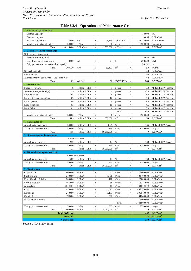
Republic of Senegal Chapter 8 Preparatory Survey for Mamelles Sea Water Desalination Plant Construction Project Final Report Project Cost Estimation
8-8
Table 8.2.4 Operation and Maintenance Cost 1. Electric cost (basic charge)
Contract Capacity 13,000 kW Basic monthly rate 9,855 F.CFA/kW Basic monthly charge 13,000 kW x 9,855 F.CFA/kW = 128,115,000 F.CFA/month Monthly production of water 50,000 m3/day x 30 days = 1,500,000 m3/month
Thus, 128,115,000 F.CFA/year / 1,500,000 m3/year = 85 F.CFA/m3 2. Electric cost (meter rate charge) Unit electric consumption
Average Electricity load 8,680 kW Daily Electricity consumption 8,680 kW x 24 h = 208,320 kWh Daily production of water (nominal capacity) 53,191 m3
Thus, 208,320 kWh / 53,191 m3 = 3.9 kWh/m3 Off-peak time rate 58 F.CFA/kWh Peak time rate 83 F.CFA/kWh Average rate (Off peak: 20 hr, Peak time: 4 hr) 62 F.CFA/kWh
Thus, 3.9 kWh/m3 x 62 F.CFA/kWh = 243 F.CFA/m3 3. Personnel cost Manager (Foreign) 8 Million F.CFA x 1 person = 8.0 Million F.CFA / month Assistant manager (Foreign) 5 Million F.CFA x 4 person = 20.0 Million F.CFA / month Local Manager 0.8 Million F.CFA x 4 person = 3.2 Million F.CFA / month Local chief operator/engineer 0.5 Million F.CFA x 12 person = 6.0 Million F.CFA / month Local operator 0.4 Million F.CFA x 6 person = 2.4 Million F.CFA / month Local technician 0.3 Million F.CFA x 15 person = 4.5 Million F.CFA / month Local Labor 0.2 Million F.CFA x 4 person = 0.8 Million F.CFA / month Total 44.9 Million F.CFA / month
Monthly production of water 50,000 m3/day x 30 days = 1,500,000 m3/month Thus, 44.9 Million F.CFA / 1,500,000 m3 = 30 F.CFA/m3
4. Maintenance cost Annual maintenance cost 54,000 Million F.CFA x 0.25 % = 135 Million F.CFA / year Yearly production of water 50,000 m3/day x 365 days = 18,250,000 m3/year
Thus, 135 Million F.CFA / 18,250,000 m3 = 7 F.CFA/m3 5. UF membrane replacement cost UF membrane cost Annual replacement cost 950 Million F.CFA 14 % = 133 Million F.CFA / year Yearly production of water 50,000 m3/day x 365 days = 18,250,000 m3/year
Thus, 133 Million F.CFA / 18,250,000 m3 = 7 F.CFA/m3 6. RO membrane replacement cost RO membrane cost Annual replacement cost 1,200 Million F.CFA 14 % = 168 Million F.CFA / year Yearly production of water 50,000 m3/day x 365 days = 18,250,000 m3/year
Thus, 168 Million F.CFA / 18,250,000 m3 = 9 F.CFA/m3 7. Chemical cost Chlorine Gas 800,000 F.CFA/t x 21 t/year = 16,800,000 F.CFA/year Sulphuric acid 240,000 F.CFA/t x 1,760 t/year = 422,400,000 F.CFA/year Ferric Chloride Solution 200,000 F.CFA/t x 110 t/year = 22,000,000 F.CFA/year Sodium Bisulfite 465,000 F.CFA/t x 35 t/year = 16,275,000 F.CFA/year Antiscalant 2,000,000 F.CFA/t x 61 t/year = 122,000,000 F.CFA/year CO2 425,000 F.CFA/t x 1,095 t/year = 465,375,000 F.CFA/year Limestone 270,000 F.CFA/t x 1,133 t/year = 305,910,000 F.CFA/year Caustic Soda 220000 F.CFA/t x 292 t/year = 64,240,000 F.CFA/year RO Chemical Cleaning 9,000,000 F.CFA/year
Total 1,444,000,000 F.CFA/year Yearly production of water 50,000 m3/day x 365 days = 18,250,000 m3/year
Thus, 1,444,000,000 F.CFA / 18,250,000 m3 = 79 F.CFA/m3 Total O&M cost 462 F.CFA/m3
Fixed cost 123 F.CFA/m3 Variable cost 339 F.CFA/m3
Source: JICA Study Team
Republic of Senegal Chapter 8 Preparatory Survey for Mamelles Sea Water Desalination Plant Construction Project Final Report Project Cost Estimation
8-9
8.2.3 Water Production Cost
Table 8.2.5 Water Production Cost of the Mamelles SWRO Plant
This part was omitted due to confidentiality.
This part was omitted due to confidentiality.
Republic of Senegal Chapter 8 Preparatory Survey for Mamelles Sea Water Desalination Plant Construction Project Final Report Project Cost Estimation
8-10
8.3 Comparison of the Construction Cost of Desalination Plant with Past Projects
In order to verify the estimated construction cost of the seawater desalination plant in the Project, the estimated cost was compared with the previous desalination projects as shown in Figure 8.3.1. The data source for the past projects is "DesalData .com/March 2015". For a valid comparison, the project cost data in the figure were extracted from the database in the following manner:
Plants that have been contracted in 2005 or later and are online or under construction
Plants between 30,000 and 70,000 m3/d capacity
Four highest and four lowest case (EPC price per capacity) omitted
Figure 8.3.1 Comparison of the Construction Cost of Seawater Desalination Facility
As shown in the above figure, the estimated cost for this project seems to be slightly higher than the average level. However, JICA Study Team concludes that the estimated cost is in a reasonable range from the comparisons with the other projects for the following reasons:
This part was omitted due to confidentiality.
Republic of Senegal Chapter 8 Preparatory Survey for Mamelles Sea Water Desalination Plant Construction Project Final Report Project Cost Estimation
8-11
It should be noted that the available cost in the DesalData is the contracted amount which reflects the competition environment in the bid. Taking into account that the estimated cost is for the feasibility study, the construction cost will be higher than the other projects’ contracted costs.
The contracted costs in the figure also reflect different technical features of the projects. Considering that the Project includes the cost for the seawater transmission pumping station of the high pump head and the transmission pipeline, the higher cost is fully possible.
The construction site of the Project is Western Africa which is not close to the equipment suppliers. Transportation costs pushes up the construction costs.
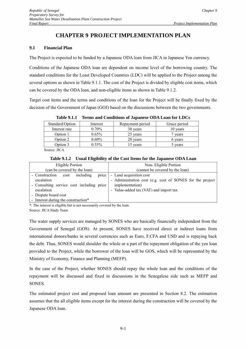
Republic of Senegal Chapter 9
Preparatory Survey for
Mamelles Sea Water Desalination Plant Construction Project
Final Report Project Implementation Plan
9-1
CHAPTER 9 PROJECT IMPLEMENTATION PLAN
9.1 Financial Plan
The Project is expected to be funded by a Japanese ODA loan from JICA in Japanese Yen currency.
Conditions of the Japanese ODA loan are dependent on income level of the borrowing country. The standard conditions for the Least Developed Countries (LDC) will be applied to the Project among the several options as shown in Table 9.1.1. The cost of the Project is divided by eligible cost items, which can be covered by the ODA loan, and non-eligible items as shown in Table 9.1.2.
Target cost items and the terms and conditions of the loan for the Project will be finally fixed by the decision of the Government of Japan (GOJ) based on the discussions between the two governments.
Table 9.1.1 Terms and Conditions of Japanese ODA Loan for LDCs
Standard/Option Interest Repayment period Grace period Interest rate 0.70% 30 years 10 years
Option 1 0.65% 25 years 7 years Option 2 0.60% 20 years 6 years Option 3 0.55% 15 years 5 years
Source: JICA
Table 9.1.2 Usual Eligibility of the Cost Items for the Japanese ODA Loan
Eligible Portion (can be covered by the loan)
Non- Eligible Portion (cannot be covered by the loan)
- Construction cost including price escalation
- Consulting service cost including price escalation
- Dispute board cost - Interest during the construction*
- Land acquisition cost - Administration cost (e.g. cost of SONES for the project
implementation) - Value-added tax (VAT) and import tax
*: The interest is eligible but is not necessarily covered by the loan. Source: JICA Study Team
The water supply services are managed by SONES who are basically financially independent from the Government of Senegal (GOS). At present, SONES have received direct or indirect loans from international donors/banks in several currencies such as Euro, F.CFA and USD and is repaying back the debt. Thus, SONES would shoulder the whole or a part of the repayment obligation of the yen loan provided to the Project, while the borrower of the loan will be GOS, which will be represented by the Ministry of Economy, Finance and Planning (MEFP).
In the case of the Project, whether SONES should repay the whole loan and the conditions of the repayment will be discussed and fixed in discussions in the Senegalese side such as MEFP and SONES.
The estimated project cost and proposed loan amount are presented in Section 8.2. The estimation assumes that the all eligible items except for the interest during the construction will be covered by the Japanese ODA loan.
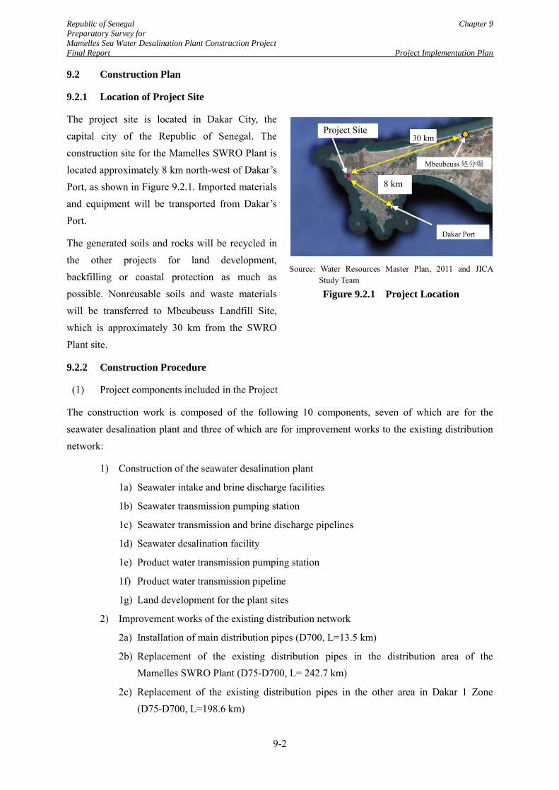
Republic of Senegal Chapter 9
Preparatory Survey for
Mamelles Sea Water Desalination Plant Construction Project
Final Report Project Implementation Plan
9-2
9.2 Construction Plan
9.2.1 Location of Project Site
The project site is located in Dakar City, the capital city of the Republic of Senegal. The construction site for the Mamelles SWRO Plant is located approximately 8 km north-west of Dakar’s Port, as shown in Figure 9.2.1. Imported materials and equipment will be transported from Dakar’s Port.
The generated soils and rocks will be recycled in the other projects for land development, backfilling or coastal protection as much as possible. Nonreusable soils and waste materials will be transferred to Mbeubeuss Landfill Site, which is approximately 30 km from the SWRO Plant site.
9.2.2 Construction Procedure
(1) Project components included in the Project
The construction work is composed of the following 10 components, seven of which are for the seawater desalination plant and three of which are for improvement works to the existing distribution network:
1) Construction of the seawater desalination plant
1a) Seawater intake and brine discharge facilities
1b) Seawater transmission pumping station
1c) Seawater transmission and brine discharge pipelines
1d) Seawater desalination facility
1e) Product water transmission pumping station
1f) Product water transmission pipeline
1g) Land development for the plant sites
2) Improvement works of the existing distribution network
2a) Installation of main distribution pipes (D700, L=13.5 km)
2b) Replacement of the existing distribution pipes in the distribution area of the Mamelles SWRO Plant (D75-D700, L= 242.7 km)
2c) Replacement of the existing distribution pipes in the other area in Dakar 1 Zone (D75-D700, L=198.6 km)
Source: Water Resources Master Plan, 2011 and JICA Study Team
Figure 9.2.1 Project Location
Project Site
Dakar Port
8 km
Mbeubeuss処分場
30 km
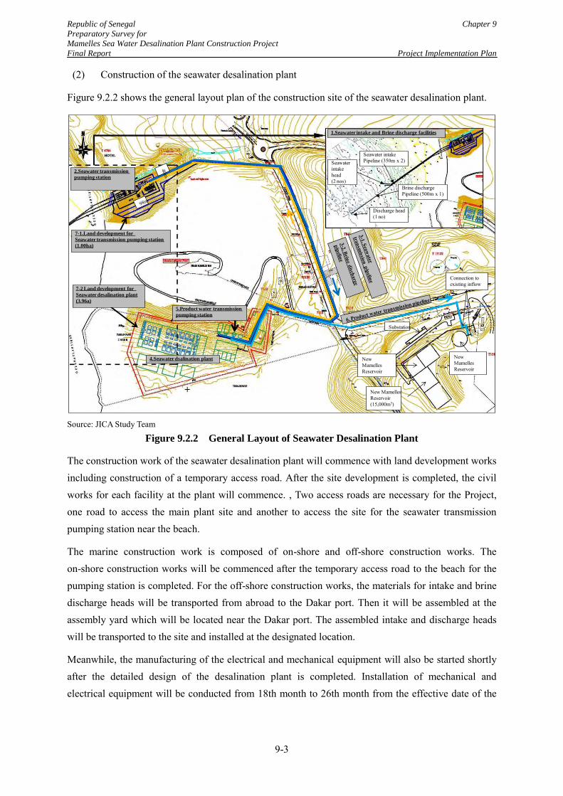
Republic of Senegal Chapter 9
Preparatory Survey for
Mamelles Sea Water Desalination Plant Construction Project
Final Report Project Implementation Plan
9-3
(2) Construction of the seawater desalination plant
Figure 9.2.2 shows the general layout plan of the construction site of the seawater desalination plant.
Source: JICA Study Team
Figure 9.2.2 General Layout of Seawater Desalination Plant
The construction work of the seawater desalination plant will commence with land development works including construction of a temporary access road. After the site development is completed, the civil works for each facility at the plant will commence. , Two access roads are necessary for the Project, one road to access the main plant site and another to access the site for the seawater transmission pumping station near the beach.
The marine construction work is composed of on-shore and off-shore construction works. The on-shore construction works will be commenced after the temporary access road to the beach for the pumping station is completed. For the off-shore construction works, the materials for intake and brine discharge heads will be transported from abroad to the Dakar port. Then it will be assembled at the assembly yard which will be located near the Dakar port. The assembled intake and discharge heads will be transported to the site and installed at the designated location.
Meanwhile, the manufacturing of the electrical and mechanical equipment will also be started shortly after the detailed design of the desalination plant is completed. Installation of mechanical and electrical equipment will be conducted from 18th month to 26th month from the effective date of the
1.Seawater intake and Brine discharge facilities
Seawater intake Pipeline (350m x 2)
Brine discharge Pipeline (500m x 1)
Seawater intake head (2 nos)
Discharge head(1 no)
2.Seawater transmission
pumping station
4.Seawater dsalination plant
5.Product water transmission
pumping station
7-1.Land development for
Seawater transmission pumping station
(1.00ha)
7-2 Land development for
Seawater desalination plant
(3.96a)
Connection toexisting inflow
Substation
New Mamelles Reservoir
New Mamelles Reservoir (15,000m3)
New Mamelles Reservoir
Source: JICA Study Team
Figure 4.11.1 Layout plan of Mamelles Seawater Desalination Plant Construction Project
Republic of Senegal Chapter 9
Preparatory Survey for
Mamelles Sea Water Desalination Plant Construction Project
Final Report Project Implementation Plan
9-4
EPC contract. The total construction period of the seawater desalination plant is envisaged to be 29 months including detailed design, construction and commissioning periods.
(3) Improvement works of the existing distribution network
Figure 9.2.3 shows the area for the improvement works to the existing distribution network.
Source: JICA Study Team
Figure 9.2.3 Target Area of the Improvement Works of the Existing Distribution Network
The improvement works of the existing network requires 442 km of pipe replacement works and renewals of the service connections and water meters. In Ouakam municipality, which is a part of the CP-3 site, the rock layer appears at 1 to 2 m depth from the surface. In the most area of Plateau municipality, which is a part of the CP-4 site, the buildings are clustered and the existing utilities such as power cables, communication cables and sewer pipes are congested in the streets. In addition, high groundwater level in Plateau requires pump-dewatering work during the pipe replacement works. The construction period of CP-3 and CP-4 needs to be planned in consideration of the low constructability in these areas.
Main distribution pipes: DN700 to Front de Terre
New Mamelles Reservoirs
SicapLiberte
Front deTerre
Dakar-Plateau
Grand Dakar
Yoff
CP-3: Replacement of the existing distribution pipes in the distribution area of the Mamelles SWRO Plant
Sector boundaries
CP-2: Installation of main distribution pipes
CP-4: Replacement of the existing distribution pipes in the other area in Dakar 1 Zone
Republic of Senegal Chapter 9
Preparatory Survey for
Mamelles Sea Water Desalination Plant Construction Project
Final Report Project Implementation Plan
9-5
JICA Study Team conducted interviews to the local construction companies who have many experiences of the similar projects ordered by SONES or SDE. Table 9.2.1 shows the interview results on the possible accomplishment per 1 shift of the pipe replacement works, replied by the local contractors, who are SVTP, EIFFAGE Senegal, SADE Senegal and GTHE.
As shown in the table, there is a wide variation in the possible accomplishment suggested by the construction companies. However, the extremely high values presented by GTHE are attributed to the fact that the company’s most works have been small PVC pipes smaller than 160mm. Observing the proposed daily construction length by the other companies, JICA Study Team views that 25 m per shift will be the moderate level as the possible performance per shift as the average in the overall CP-3 and CP-4. This will be a reasonably safety assumption because the areas with the difficult construction conditions are not predicted in the all construction sites of CP-3 and CP-4.
According to SONES, as for the other important factors in estimation of the construction period, the construction areas will allow 2 shifts in each construction site. In addition, SONES considers that the construction works would be permitted by the local municipalities if the number of the simultaneous construction sites is 10 or less.
From the conditions above, JICA Study Team calculates the construction period of CP-3 and CP-4 at 36 months, in addition to 1 month for the handing-over period.
For CP-2, possible accomplishment is assumed at 15 m per shift because the pipe diameter is much larger than CP-3 or CP-4 and the construction site includes the Ouakam municipality, where the shallow rock layer exists. Furthermore, only one shift at night time is predicted to avoid the adverse impact on the transportation in the Airport Road, one of the trunk roads in Dakar. Consequently, the construction period of CP-2 will also be 36 month, excluding one month for the handing-over period to SONES.
During the replacement works of the existing distribution pipes, temporary suspensions of the water supply services will be necessary but they should be limited to short periods for the switching works from the existing service connections to the new service connections. The contractors should communicate with the Affermage contractor, who is in charge of the operation of the water supply system, so that the Project’s impacts on the civic life and the economic activities would be minimized. In addition, the service suspension should be informed with the date and duration in advance to the all water users in the affected area.
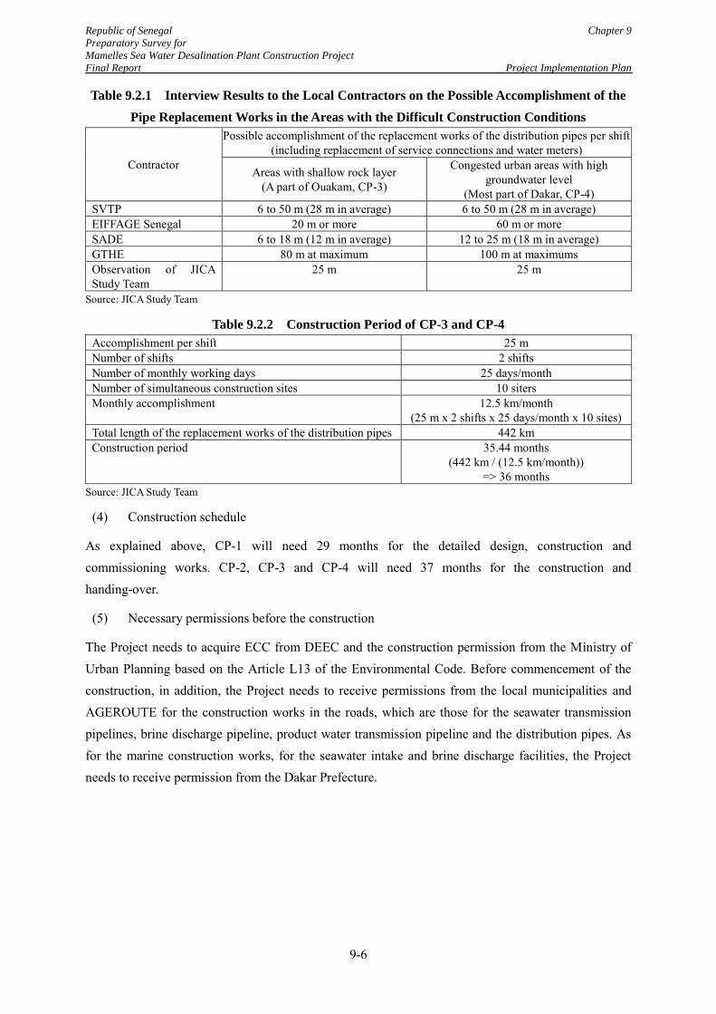
Republic of Senegal Chapter 9
Preparatory Survey for
Mamelles Sea Water Desalination Plant Construction Project
Final Report Project Implementation Plan
9-6
Table 9.2.1 Interview Results to the Local Contractors on the Possible Accomplishment of the
Pipe Replacement Works in the Areas with the Difficult Construction Conditions
Contractor
Possible accomplishment of the replacement works of the distribution pipes per shift (including replacement of service connections and water meters)
Areas with shallow rock layer (A part of Ouakam, CP-3)
Congested urban areas with high groundwater level
(Most part of Dakar, CP-4) SVTP 6 to 50 m (28 m in average) 6 to 50 m (28 m in average) EIFFAGE Senegal 20 m or more 60 m or more SADE 6 to 18 m (12 m in average) 12 to 25 m (18 m in average) GTHE 80 m at maximum 100 m at maximums Observation of JICA Study Team
25 m 25 m
Source: JICA Study Team
Table 9.2.2 Construction Period of CP-3 and CP-4
Accomplishment per shift 25 m Number of shifts 2 shifts Number of monthly working days 25 days/month Number of simultaneous construction sites 10 siters Monthly accomplishment 12.5 km/month
(25 m x 2 shifts x 25 days/month x 10 sites) Total length of the replacement works of the distribution pipes 442 km Construction period 35.44 months
(442 km / (12.5 km/month)) => 36 months
Source: JICA Study Team
(4) Construction schedule
As explained above, CP-1 will need 29 months for the detailed design, construction and commissioning works. CP-2, CP-3 and CP-4 will need 37 months for the construction and handing-over.
(5) Necessary permissions before the construction
The Project needs to acquire ECC from DEEC and the construction permission from the Ministry of Urban Planning based on the Article L13 of the Environmental Code. Before commencement of the construction, in addition, the Project needs to receive permissions from the local municipalities and AGEROUTE for the construction works in the roads, which are those for the seawater transmission pipelines, brine discharge pipeline, product water transmission pipeline and the distribution pipes. As for the marine construction works, for the seawater intake and brine discharge facilities, the Project needs to receive permission from the Dakar Prefecture.
Republic of Senegal Chapter 9
Preparatory Survey for
Mamelles Sea Water Desalination Plant Construction Project
Final Report Project Implementation Plan
9-7
9.3 Procurement Plan
9.3.1 Contract package (CP)
(1) CP-1: Construction of the seawater desalination plant
In order for the utmost utilization of know-how of the Engineering, Procurement and Construction (EPC) contractor for the Project of good quality and cost saving, the component [1d: seawater desalination plant] will be constructed by design & build (D&B) contract, which is the most common method in the similar projects worldwide.
Moreover, it is proposed that the other components related to the desalination plant [Components 1a, 1b, 1c, 1e, 1f, and 1g] are also integrated into the above D&B contract for the reasons as shown in Table 9.3.1. The procurement method will be International Competitive Bid (ICB).
Table 9.3.1 Reason for Integration into One D&B Contract
Component Reason for Integration to the desalination plant
1a: Seawater intake and brine discharge facilities
- The design of the seawater intake and brine discharge facilities are a part of the overall seawater desalination system.
- Design of the seawater affects seawater quality to be fed to the seawater desalination plant.
1b: Seawater transmission pumping station
1c: Sea water transmission and brine discharge pipelines
- The pumping station and the pipelines are physically located between the seawater intake facility, brine discharge facility and the seawater desalination facility.
- Hydraulic design of the pumps and the pipeline are linked with the hydraulic plan of the seawater desalination plant.
- Operation of the pumping station needs to be integrated to the system of the seawater desalination plant.
1e: Product water transmission pump station
1f: Product water transmission pipeline
- The pumping station will be constructed on the mainland of the seawater desalination plant.
- Hydraulic design of the pumps and the pipeline are linked with the hydraulic plan of the seawater desalination plant.
- Operation of the pumping station needs to be integrated to the system for the seawater desalination plant.
- Estimated construction costs of these components are about 110 million yen in total, which is too small to attract international bidders.
1g: Land development for the desalination plant and pump station
- The land development plan is closely related to the design of desalination plant and pumping station and cannot be conducted separately.
Source: JICA Study Team
(2) CP-2, 3 and 4: Improvement works of the existing distribution network
The improvement works of the existing distribution network need to be designed by the consultant who has knowledge of the hydraulics of water distribution network and water loss reduction. Therefore, these packages will apply Design-Bid-Building method.
The construction works are the conventional works for water supply facility construction such as installation of water supply pipes, service connections and the appurtenance such as valves and water meters. There are several experienced Senegalese contractors capable of handling these conventional works. Thus, local competitive bidding (LCB) will be possible in these packages. However, ICB will
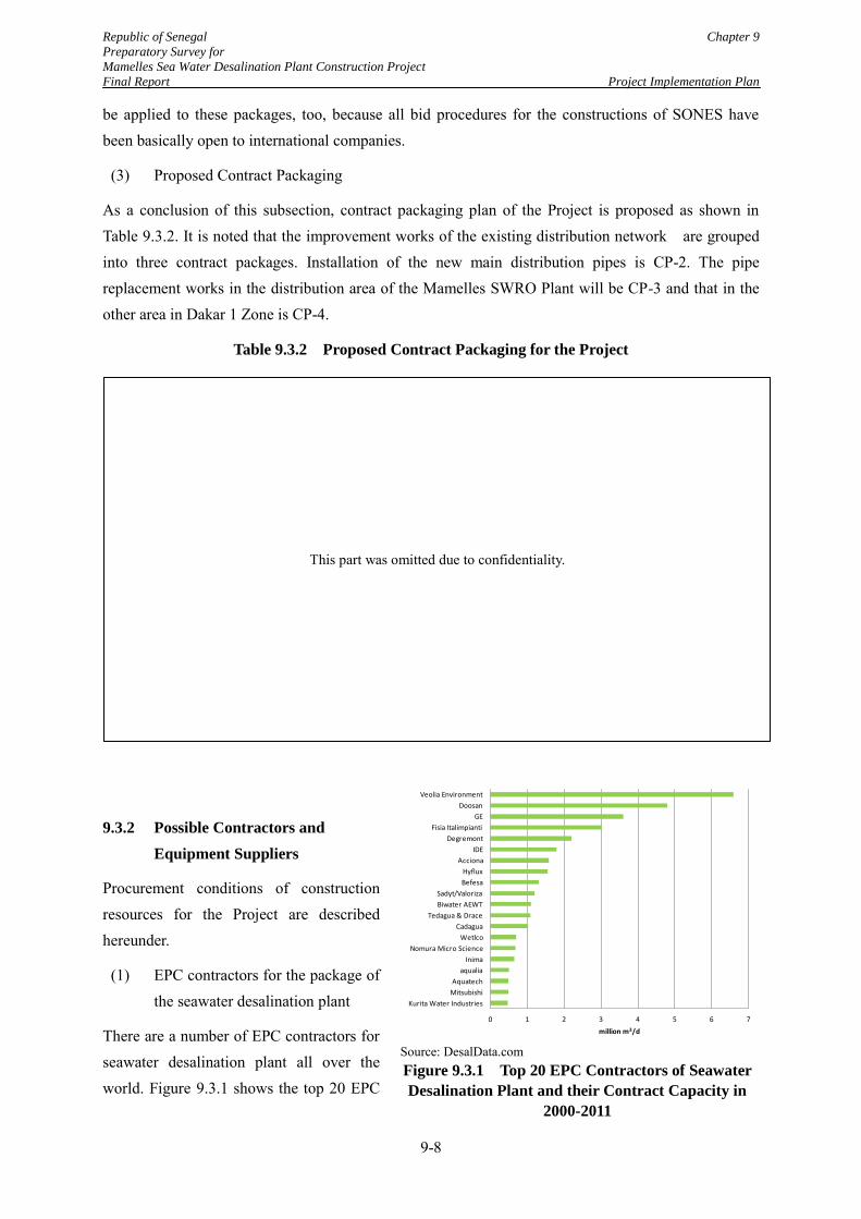
Republic of Senegal Chapter 9
Preparatory Survey for
Mamelles Sea Water Desalination Plant Construction Project
Final Report Project Implementation Plan
9-8
be applied to these packages, too, because all bid procedures for the constructions of SONES have been basically open to international companies.
(3) Proposed Contract Packaging
As a conclusion of this subsection, contract packaging plan of the Project is proposed as shown in Table 9.3.2. It is noted that the improvement works of the existing distribution network are grouped into three contract packages. Installation of the new main distribution pipes is CP-2. The pipe replacement works in the distribution area of the Mamelles SWRO Plant will be CP-3 and that in the other area in Dakar 1 Zone is CP-4.
Table 9.3.2 Proposed Contract Packaging for the Project
9.3.2 Possible Contractors and
Equipment Suppliers
Procurement conditions of construction resources for the Project are described hereunder.
(1) EPC contractors for the package of the seawater desalination plant
There are a number of EPC contractors for seawater desalination plant all over the world. Figure 9.3.1 shows the top 20 EPC
Source: DesalData.com Figure 9.3.1 Top 20 EPC Contractors of Seawater
Desalination Plant and their Contract Capacity in
2000-2011
0 1 2 3 4 5 6 7
Kurita Water Industries
Mitsubishi
Aquatech
aqualia
Inima
Nomura Micro Science
Wetlco
Cadagua
Tedagua & Drace
Biwater AEWT
Sadyt/Valoriza
Befesa
Hyflux
Acciona
IDE
Degremont
Fisia Italimpianti
GE
Doosan
Veolia Environment
million m3/d
This part was omitted due to confidentiality.
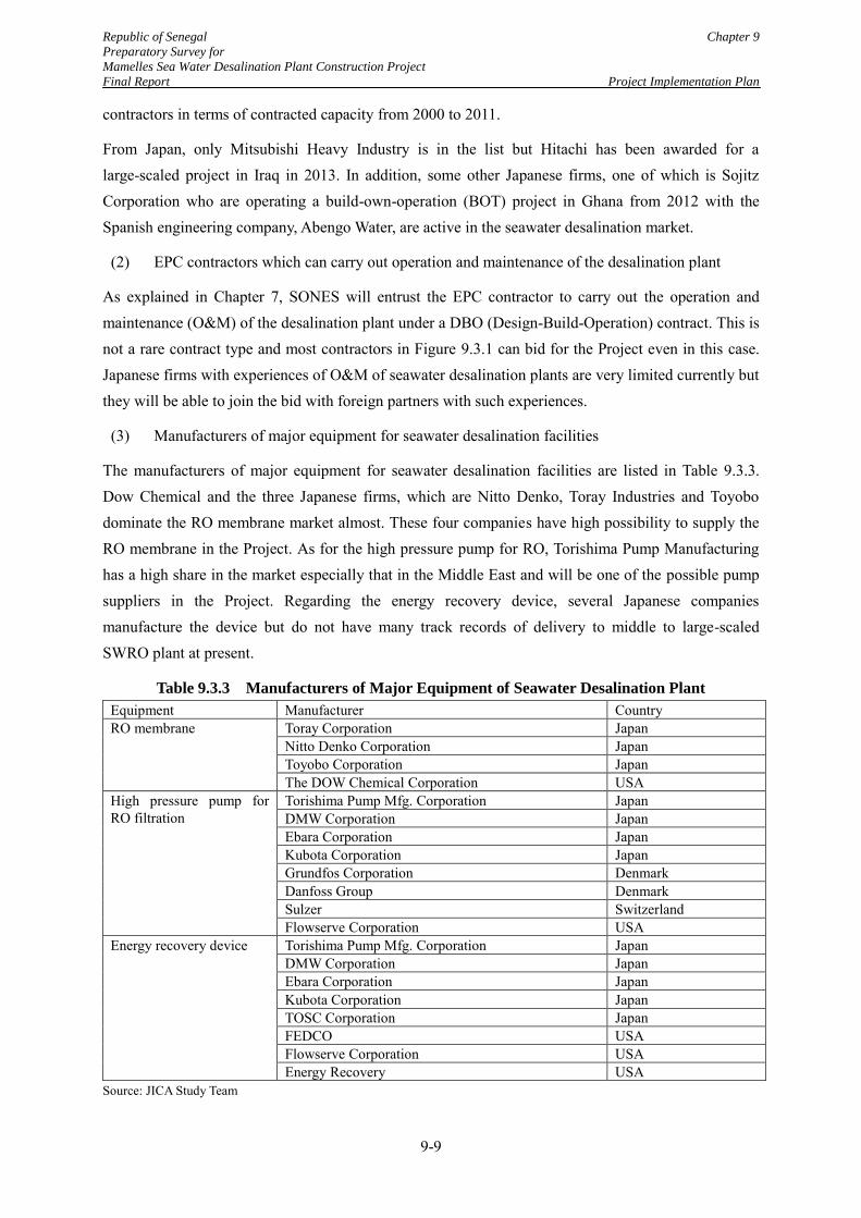
Republic of Senegal Chapter 9
Preparatory Survey for
Mamelles Sea Water Desalination Plant Construction Project
Final Report Project Implementation Plan
9-9
contractors in terms of contracted capacity from 2000 to 2011.
From Japan, only Mitsubishi Heavy Industry is in the list but Hitachi has been awarded for a large-scaled project in Iraq in 2013. In addition, some other Japanese firms, one of which is Sojitz Corporation who are operating a build-own-operation (BOT) project in Ghana from 2012 with the Spanish engineering company, Abengo Water, are active in the seawater desalination market.
(2) EPC contractors which can carry out operation and maintenance of the desalination plant
As explained in Chapter 7, SONES will entrust the EPC contractor to carry out the operation and maintenance (O&M) of the desalination plant under a DBO (Design-Build-Operation) contract. This is not a rare contract type and most contractors in Figure 9.3.1 can bid for the Project even in this case. Japanese firms with experiences of O&M of seawater desalination plants are very limited currently but they will be able to join the bid with foreign partners with such experiences.
(3) Manufacturers of major equipment for seawater desalination facilities
The manufacturers of major equipment for seawater desalination facilities are listed in Table 9.3.3. Dow Chemical and the three Japanese firms, which are Nitto Denko, Toray Industries and Toyobo dominate the RO membrane market almost. These four companies have high possibility to supply the RO membrane in the Project. As for the high pressure pump for RO, Torishima Pump Manufacturing has a high share in the market especially that in the Middle East and will be one of the possible pump suppliers in the Project. Regarding the energy recovery device, several Japanese companies manufacture the device but do not have many track records of delivery to middle to large-scaled SWRO plant at present.
Table 9.3.3 Manufacturers of Major Equipment of Seawater Desalination Plant
Equipment Manufacturer Country RO membrane Toray Corporation Japan
Nitto Denko Corporation Japan Toyobo Corporation Japan The DOW Chemical Corporation USA
High pressure pump for RO filtration
Torishima Pump Mfg. Corporation Japan DMW Corporation Japan Ebara Corporation Japan Kubota Corporation Japan Grundfos Corporation Denmark Danfoss Group Denmark Sulzer Switzerland Flowserve Corporation USA
Energy recovery device Torishima Pump Mfg. Corporation Japan DMW Corporation Japan Ebara Corporation Japan Kubota Corporation Japan TOSC Corporation Japan FEDCO USA Flowserve Corporation USA Energy Recovery USA
Source: JICA Study Team
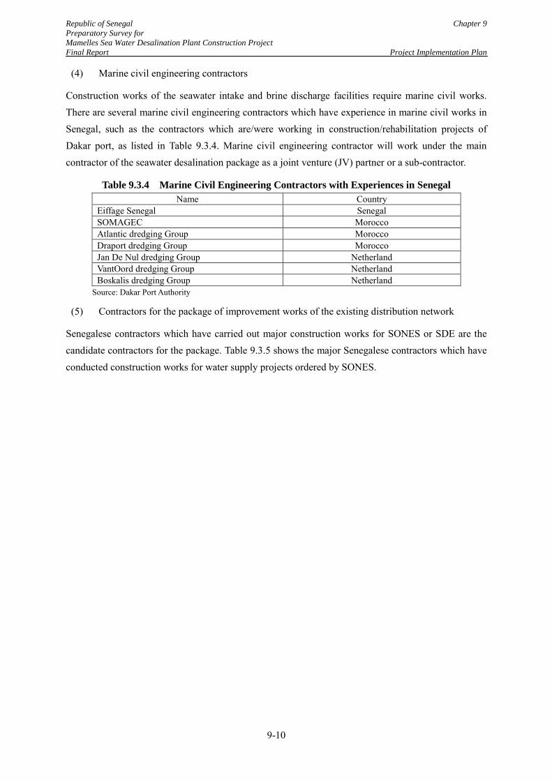
Republic of Senegal Chapter 9
Preparatory Survey for
Mamelles Sea Water Desalination Plant Construction Project
Final Report Project Implementation Plan
9-10
(4) Marine civil engineering contractors
Construction works of the seawater intake and brine discharge facilities require marine civil works. There are several marine civil engineering contractors which have experience in marine civil works in Senegal, such as the contractors which are/were working in construction/rehabilitation projects of Dakar port, as listed in Table 9.3.4. Marine civil engineering contractor will work under the main contractor of the seawater desalination package as a joint venture (JV) partner or a sub-contractor.
Table 9.3.4 Marine Civil Engineering Contractors with Experiences in Senegal
Name Country Eiffage Senegal Senegal SOMAGEC Morocco Atlantic dredging Group Morocco Draport dredging Group Morocco Jan De Nul dredging Group Netherland VantOord dredging Group Netherland Boskalis dredging Group Netherland
Source: Dakar Port Authority
(5) Contractors for the package of improvement works of the existing distribution network
Senegalese contractors which have carried out major construction works for SONES or SDE are the candidate contractors for the package. Table 9.3.5 shows the major Senegalese contractors which have conducted construction works for water supply projects ordered by SONES.
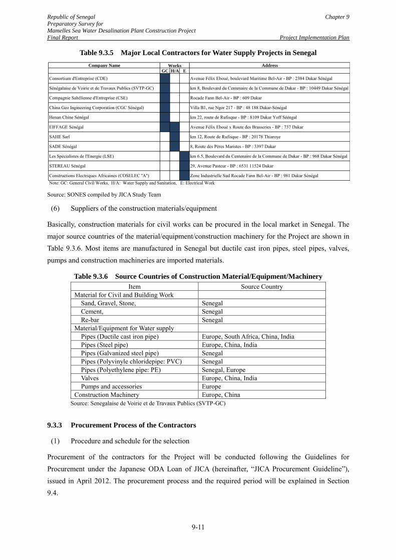
Republic of Senegal Chapter 9
Preparatory Survey for
Mamelles Sea Water Desalination Plant Construction Project
Final Report Project Implementation Plan
9-11
Table 9.3.5 Major Local Contractors for Water Supply Projects in Senegal
Source: SONES compiled by JICA Study Team
(6) Suppliers of the construction materials/equipment
Basically, construction materials for civil works can be procured in the local market in Senegal. The major source countries of the material/equipment/construction machinery for the Project are shown in Table 9.3.6. Most items are manufactured in Senegal but ductile cast iron pipes, steel pipes, valves, pumps and construction machineries are imported materials.
Table 9.3.6 Source Countries of Construction Material/Equipment/Machinery
Item Source Country Material for Civil and Building Work
Sand, Gravel, Stone, Senegal Cement, Senegal Re-bar Senegal
Material/Equipment for Water supply Pipes (Ductile cast iron pipe) Europe, South Africa, China, India Pipes (Steel pipe) Europe, China, India Pipes (Galvanized steel pipe) Senegal Pipes (Polyvinyle chloridepipe: PVC) Senegal Pipes (Polyethylene pipe: PE) Senegal, Europe Valves Europe, China, India Pumps and accessories Europe
Construction Machinery Europe, China Source: Senegalaise de Voirie et de Travaux Publics (SVTP-GC)
9.3.3 Procurement Process of the Contractors
(1) Procedure and schedule for the selection
Procurement of the contractors for the Project will be conducted following the Guidelines for Procurement under the Japanese ODA Loan of JICA (hereinafter, “JICA Procurement Guideline”), issued in April 2012. The procurement process and the required period will be explained in Section 9.4.
Company Name Address
GC H/A E
Consortium d'Entreprise (CDE) Avenue Félix Eboué, boulevard Maritime Bel-Air - BP : 2384 Dakar Sénégal
Sénégalaise de Voirie et de Travaux Publics (SVTP-GC) km 8, Boulevard du Centenaire de la Commune de Dakar - BP : 10449 Dakar Sénégal
Compagnie Sahélienne d'Entreprise (CSE) Rocade Fann Bel-Air - BP : 609 Dakar
China Geo Ingineering Corporation (CGC Sénégal) Villa B1, rue Ngor 217 - BP : 48 188 Dakar-Sénégal
Henan Chine Sénégal km 22, route de Rufisque - BP : 8109 Dakar Yoff Sééngal
EIFFAGE Sénégal Avenue Félix Eboué x Route des Brasseries - BP : 737 Dakar
SAHE Sarl km 12, Route de Rufisque - BP : 20178 Thiaroye
SADE Sénégal 8, Route des Pères Maristes - BP : 3397 Dakar
Les Spécialistes de l'Energie (LSE) km 6.5, Boulevard du Centenaire de la Commune de Dakar - BP : 968 Dakar Sénégal
STEREAU Sénégal 29, Avenue Pasteur - BP : 6531 11524 Dakar
Constructions Electriques Africaines (COSELEC ''A'') Zone Industrielle Sud Rocade Fann Bel-Air - BP : 981 Dakar SénégalNote: GC: General Civil Works, H/A: Water Supply and Sanitation, E: Electrical Work
Works
Republic of Senegal Chapter 9
Preparatory Survey for
Mamelles Sea Water Desalination Plant Construction Project
Final Report Project Implementation Plan
9-12
(2) Proposal on the selection method of the EPC contractor
The EPC contractor will be selected through the bid where the technical and financial proposals of the bidders are evaluated. The JICA Study Team proposes that the financial evaluation will the total evaluation of the construction and O&M costs. This selection method will motivate the bidders to design the desalination plant with the best balance in the construction and O&M costs, which will benefit SONES and mitigate the project’s impact on the water rate.
Evaluation criteria for the selection, which will include the period to count the O&M cost and conditions of the cost estimations, will be proposed by the consultant to provide the tender assistance for the Project. Possible period for the O&M cost calculation in the bid will be eight years, which are the O&M period under the DBO contract proposed in Section 7.2.4, or 15 to 20 years, which are the usual life of the overall mechanical and electrical equipment.
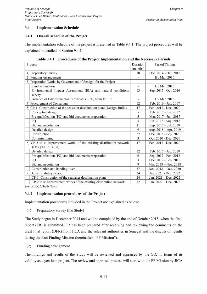
Republic of Senegal Chapter 9
Preparatory Survey for
Mamelles Sea Water Desalination Plant Construction Project
Final Report Project Implementation Plan
9-13
9.4 Implementation Schedule
9.4.1 Overall schedule of the Project
The implementation schedule of the project is presented in Table 9.4.1. The project procedures will be explained in detailed in Section 9.4.1.
Table 9.4.1 Procedures of the Project Implementation and the Necessary Periods
Process Duration (months)
Period/Timing
1) Preparatory Survey 10 Dec. 2014 - Oct. 2015 2) Funding Arrangement - By Mar. 2016 3) Preparation Works by Government of Senegal for the Project - - Land acquisition - By Mar. 2016 Environmental Impact Assessment (EIA) and natural conditions
survey 13 Sep. 2015 - Oct. 2016
Issuance of Environmental Certificate (ECC) from DEEC - By Mar. 2016 4) Procurement of Consultant 12 Feb. 2016 - Jan. 2017 5) CP-1: Construction of the seawater desalination plant (Design-Build) 47 Feb. 2017 - Dec. 2020 Conceptual design 5 Feb. 2017 –Jun. 2017 Pre-qualification (PQ) and bid documents preparation 5 Mar. 2017 - Jul.. 2017 PQ 3 Jun. 2017 - Aug. 2018 Bid and negotiation 11 Sep. 2017 – Jul. 2018 Detailed design 9 Aug. 2018 – Apr. 2019 Construction 22 Dec. 2018 - Sep. 2020 Commissioning 3 Oct. 2020 - Dec. 2020 6) CP-2 to 4: Improvement works of the existing distribution network
(Design-Bid-Build) 47 Feb. 2017 - Dec. 2020
Detailed design 12 Feb. 2017 - Jan. 2018 Pre-qualification (PQ) and bid documents preparation 6 Sep. 2017 - Feb. 2018 PQ 3 Dec. 2017 - Feb. 2018 Bid and negotiation 9 Mar. 2018 – Nov. 2018 Construction and handing-over 37 Dec. 2018 – Dec. 2020 7) Defect Liability Period 24 Jan. 2021 - Dec. 2022 CP-1: Construction of the seawater desalination plant 24 Jan. 2021 – Dec. 2022 CP-2 to 4: Improvement works of the existing distribution network 12 Jan. 2022 – Dec. 2022
Source: JICA Study Team
9.4.2 Implementation procedures of the Project
Implementation procedures included in the Project are explained as below;
(1) Preparatory survey (the Study)
The Study began in December 2014 and will be completed by the end of October 2015, when the final report (FR) is submitted. FR has been prepared after receiving and reviewing the comments on the draft final report (DFR) from JICA and the relevant authorities in Senegal and the discussion results during the Fact Finding Mission (hereinafter, “FF Mission”).
(2) Funding arrangement
The findings and results of the Study will be reviewed and appraised by the GOJ in terms of its validity as a yen loan project. The review and appraisal process will start with the FF Mission by JICA,
Republic of Senegal Chapter 9
Preparatory Survey for
Mamelles Sea Water Desalination Plant Construction Project
Final Report Project Implementation Plan
9-14
who will collect overall information relevant to the validity of the Project as a yen loan project based on the DFR in August 2015. After the delivery of the FR, the Appraisal Mission of JICA will hold final discussions with the GOS and SONES on the technical, financial, economical, environmental and social validities and on the conditions of the yen loan in detail. Results of the discussions agreed during the Appraisal Mission will be recorded in the minutes of discussions (MD), to be signed by JICA, the GOS and SONES.
Based on the appraisal results, the GOJ will send “pledge” to the GOS, which will notice the decision to provide the loan to the Project and the terms and conditions of the loan. Subsequently, the two governments will hold final discussions, after which exchange of the notes (EN) and conclusion of the loan agreement (LA) will be done. If the all discussions between the two governments proceed in a smooth manner, the loan agreement will be signed by March 2016.
(3) Preparation works by the GOS and SONES for the Project
In parallel with the Study and the funding arrangement, the GOS and SONES will carry out the necessary preparation works for the Project. The preparation works include land acquisition, the EIA and bathymetric survey by SONES, issuance of ECC, and other internal arrangement in the GOS.
As shown in Figure 9.4.1, the EIA and issuance of ECC is the critical path up to the expected loan agreement by March 2016. Especially, SONES is required to share the “Initial Notes” of EIA with JICA by the end of November, which will present that the Project has no critical environmental or social problem, as described in Section 6.7.1. The kick-off meeting between SONES and the consultant has just been carried out on 30th September. Efficient implementation of the EIA by SONES is necessary to enable on-time delivery of the Project. Further delay of the EIA Study may cause a delay to the entire process of the loan agreement.
(4) Procurement of consultant
SONES will procurement a consultancy company for the Project based on the JICA Procurement Guideline. The procurement process can begin after the GOJ pledges the yen loan to GOS. The procurement will take eleven months from the issuance of request for expression of interest (EOI), until completion of the bid, which will be followed by negotiations and sign on the contracts. RFP needs concurrence from JICA before its delivery to the consultancy companies who are nominated in the shortlist, and the selection result of the consultancy company and the signed contract also need JICA’s concurrence respectively. Review period by JICA will be 15 days in principle for each concurrence.
(5) Contract Package (CP)-1: Construction of the seawater desalination plant (Design-Build package)
The contractor for CP-1 will be procured based on the JICA Procurement Guideline. The awarded consultancy company will carry out the conceptual design and the preparation of PQ and bid documents. Subsequently the consultancy company will assist SONES in PQ and bid procedures. It is
Republic of Senegal Chapter 9
Preparatory Survey for
Mamelles Sea Water Desalination Plant Construction Project
Final Report Project Implementation Plan
9-15
noted that the concurrences of JICA are necessary to the PQ document, PQ evaluation results, bid document, bid evaluation results and the signed contract respectively. Review period by JICA will be 15 days in principle for each concurrence.
The contractor will carry out detailed design, construction and commissioning works. From practices in the desalination plant projects worldwide, 29 months is assumed as the total period of the detailed design, construction and commissioning works. The consultancy company will supervise the contractor's work until completion of the commissioning.
The contract with the contractor will be DBO, which will include O&M works. However, the consultancy services will not include the supervision during the O&M period but finish at the end of the defect liability period.
(6) Contract Package (CP)-2 to 4: Improvement works of the existing distribution network (Design-Bid-Build package)
The contractors for CP-2 to CP-4 will be procured based on the JICA Procurement Guideline. The awarded consultancy company will carry out detailed design and preparation of PQ and bid documents, and subsequently the consultancy company will assist SONES in PQ and bid procedures. In the same way as CP-1, JICA concurrences are necessary to the documents, evaluation results and the contract in the procurement process.
The Contractor will carry out construction and commissioning works based on the detailed design by the consultancy company. The consultancy company will supervise the contractor's work until completion of the handing-over of the all facilities to SONES.
(7) Defect liability period (DLP)
DLP of the project is assumed to be two years after completion of the commissioning for CP-1 and one year after the handing-over for CP-2 to CP-4. The consultancy company will assist SONES in the inspections of the facilities and communications with the contractors during the period.
In Senegal, the minimum DLP period is stipulated as one year by Article L16 of the Construction Code (LOI No. 2009-23). In the Project, the minimum period will be applied to CP-2 to CP-4, which are the conventional construction works. On the other hand, the longer LDP will be applied to CP-1 because the SWRO plant includes advanced technologies and equipment which are not familiar in the country. In the past projects of SONES, construction projects of KMS1 and 2 have applied two-year DLP.
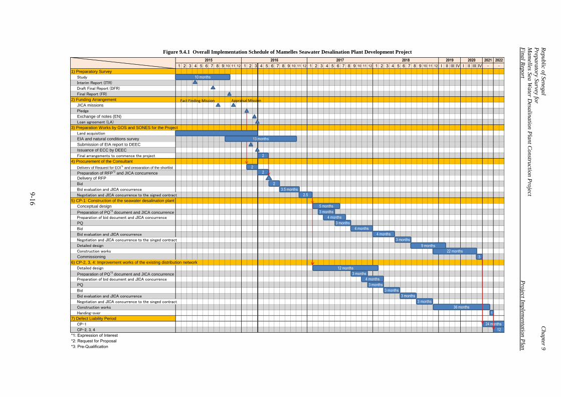
Rep
ublic o
f Sen
ega
l C
ha
pter 9
Prep
ara
tory S
urvey fo
r
Ma
melles S
ea W
ater D
esalin
atio
n P
lan
t Co
nstru
ction
Pro
ject
Fin
al R
epo
rt P
roject Im
plem
enta
tion
Pla
n
9 -16
1 2 3 4 5 6 7 8 9 10 11 12 1 2 3 4 5 6 7 8 9 10 11 12 1 2 3 4 5 6 7 8 9 10 11 12 1 2 3 4 5 6 7 8 9 10 11 12 I II III IV I II III IV
1) Preparatory Survey
Study
Interim Report (ITR)
Draft Final Report (DFR)
Final Report (FR)
2) Funding Arrangement
JICA missions
Pledge
Exchange of notes (EN)
Loan agreement (LA)
3) Preparation Works by GOS and SONES for the Project
Land acquisition
EIA and natural conditions survey
Submission of EIA report to DEEC
Issuance of ECC by DEEC
Final arrangements to commence the project
4) Procurement of the Consultant
Delivery of Request for EOI*1
and preparation of the shortlist
Preparation of RFP*2
and JICA concurrence
Delivery of RFP
Bid
Bid evaluation and JICA concurrence
Negotiation and JICA concurrence to the signed contract
5) CP-1: Construction of the seawater desalination plant
Conceptual design
Preparation of PQ*3
document and JICA concurrence
Preparation of bid document and JICA concurrence
PQ
Bid
Bid evaluation and JICA concurrence
Negotiation and JICA concurrence to the singed contract
Detailed design
Construction works
Commissioning
6) CP-2, 3, 4: Improvement works of the existing distribution network
Detailed design
Preparation of PQ*3
document and JICA concurrence
Preparation of bid document and JICA concurrence
PQ
Bid
Bid evaluation and JICA concurrence
Negotiation and JICA concurrence to the singed contract
Construction works
Handing-over
7) Defect Liability Period
CP-1
CP-2, 3, 4
*1: Expression of Interest
*2: Request for Proposal
*3: Pre-Qualification
2019 2020 2021 2022
- -
Figure 9.4.1 Overall Implementation Schedule of Mamelles Seawater Desalination Plant Development Project
2015 2016 2017 2018
10 months
13 months
2
4 months
3 months
5 months
2
2
12 months
3 months
2
22 months
3
Fact Finding Mission Appraisal Mission
2.5
3.5 months
4 months
3 months
4 months
9 months
24 months
3 months
3 months
36 months
1
4 months
3 months
12
3 months
3 months
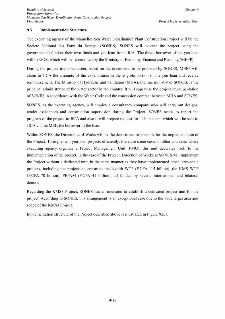
Republic of Senegal Chapter 9
Preparatory Survey for
Mamelles Sea Water Desalination Plant Construction Project
Final Report Project Implementation Plan
9-17
9.5 Implementation Structure
The executing agency of the Mamelles Sea Water Desalination Plant Construction Project will be the Societe National des Eaux du Senegal (SONES). SONES will execute the project using the governmental fund or their own funds and yen loan from JICA. The direct borrower of the yen loan will be GOS, which will be represented by the Ministry of Economy, Finance and Planning (MEFP).
During the project implementation, based on the documents to be prepared by SONES, MEFP will claim to JICA the amounts of the expenditures in the eligible portion of the yen loan and receive reimbursement. The Ministry of Hydraulic and Sanitation (MHA), the line ministry of SONES, is the principal administrator of the water sector in the country. It will supervise the project implementation of SONES in accordance with the Water Code and the concession contract between MHA and SONES.
SONES, as the executing agency, will employ a consultancy company who will carry out designs, tender assistances and construction supervision during the Project. SONES needs to report the progress of the project to JICA and also it will prepare request for disbursement which will be sent to JICA via the MEF, the borrower of the loan.
Within SONES, the Directorate of Works will be the department responsible for the implementation of the Project. To implement yen loan projects efficiently, there are some cases in other countries where executing agency organize a Project Management Unit (PMU), this unit dedicates itself to the implementation of the project. In the case of the Project, Direction of Works at SONES will implement the Project without a dedicated unit, in the same manner as they have implemented other large-scale projects, including the projects to construct the Ngnith WTP (F.CFA 115 billion) ,the KMS WTP (F.CFA 70 billion), PEPAM (F.CFA 41 billion), all funded by several international and bilateral donors.
Regarding the KMS3 Project, SONES has an intension to establish a dedicated project unit for the project. According to SONES, this arrangement is an exceptional case due to the wide target area and scope of the KMS3 Project.
Implementation structure of the Project described above is illustrated in Figure 9.5.1.
Republic of Senegal Chapter 9
Preparatory Survey for
Mamelles Sea Water Desalination Plant Construction Project
Final Report Project Implementation Plan
9-18
Source: JICA Study Team
Figure 9.5.1 Implementation Structure of the Project
MEFP(Ministry of Economy, Finance and
Planning)
MHA(Ministry of Hydraulic and
Sanitation)
EXECUTING AGENCYSONES
(Societe National des Eaux du Senegal)Responsible department
Directorate of Works
Consultant Contractors
Loan Agreement
Draft request for disbursement
JICA(Japan International Corporation
Agency)
BORROWER Government of Senegal (GOS)
Supervision
Contract ofconsulting services
Contracts ofconstructions
Supervision
Report ing of progress
Request for disbursement
Disbursement
Republic of Senegal Chapter 9
Preparatory Survey for
Mamelles Sea Water Desalination Plant Construction Project
Final Report Project Implementation Plan
9-19
9.6 Proposal on Terms of Reference of the Consulting Services
(1) General
Terms of Reference (TOR) of the Consulting Services will be an important part of the tender document for procurement of a consultancy company for the Project, which is usually called as request for proposal (RFP). TOR describes 1) Background, 2) Objectives of the Consulting Services, 3) Scope of the Consulting Services, 4) Expected time schedule, 5) Staffing, 6) Reporting and 7) Undertakings by the Client. Proposed TOR is presented in Appendix 9 and the outlines of the TOR are described as below:
(2) Scope of the Consultancy Company
Scope of the Consultancy Company includes the following work items:
a) Conceptual design of CP-1
b) Detailed design of CP-2 to CP-4
c) Tender assistance
d) Construction supervision including the assistance during DLP
e) Facilitation of implementation of Environmental Management Plan (EMP) and Environmental Monitoring Plan (EMoP)
(3) Expected time schedule
Necessary period for the Consultancy Services is 71 months which covers all works from design phase to the construction supervision phase including a two-year DLP. Expected time schedule of the Consulting Services is from February 2017 to the end of 2022.
(4) Staffing
(5) Estimated Cost for the Consulting Services
This part was omitted due to confidentiality.
This part was omitted due to confidentiality.
Republic of Senegal Chapter 10 Preparatory Survey for Mamelles Sea Water Desalination Plant Construction Project Financial and Final Report Economic Analysis
CHAPTER 10 FINANCIAL AND ECONOMIC ANALYSIS
In this chapter, viability of the project is evaluated from the viewpoints of financial and economic aspects. Firstly, the financial analysis is conducted focusing on the predicted incremental revenue and cost as a result of by the project implementation. Secondly, the economic analysis is conducted by estimating the economic cost and quantifying economic benefits on the society which is produced by the project implementation. Finally, the future tariff setting is analysed by reviewing the result of tariff study funded by the PEPAM project and the analysis of JICA Study Team.
10.1 Assumptions
10.1.1 Basic Assumptions
The following assumptions are used for both the financial analysis and economic analysis.
(1) Exchange rates
USD 1.0 = JPY 120.2 = F.CFA 588.9, F.CFA1.0 = JPY 0.204 (as of October, 2015)
(2) Evaluation period
The evaluation period is set as 30 years including 6 years of consulting services and construction period.
(3) Life period
The life period of the civil and architectural facilities is estimated at 50 years and that of the mechanical and
electrical equipments is set at 20 years. The life period here means the actual usage period of the facilities and
equipments utilized in the project. The period length could be different from the amortization period for
accounting purposes.
(4) Inflation
The influence of inflation is not considered in the calculation for cost or revenue.
(5) Project components
The Project has two major categories of the construction works which are "the construction of seawater desalination plant" and "improvement works of the existing distribution network" which are composed of nine detailed components. For the financial and economic analyses, these components are grouped into two categories which are "(i) water production portion" and "(ii) water recovery portion" as these portion brings about different financial and economic impacts on the society.
10-1
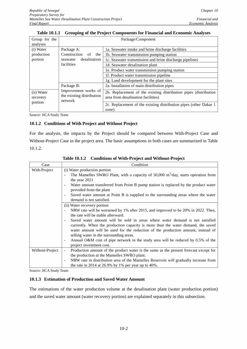
Republic of Senegal Chapter 10 Preparatory Survey for Mamelles Sea Water Desalination Plant Construction Project Financial and Final Report Economic Analysis
Table 10.1.1 Grouping of the Project Components for Financial and Economic Analyses Group for the analyses
Package/Component
(i) Water production portion
Package A: Construction of the seawater desalination facilities
1a. Seawater intake and brine discharge facilities 1b. Seawater transmission pumping station 1c. Seawater transmission and brine discharge pipelines 1d. Seawater desalination plant 1e. Product water transmission pumping station 1f. Product water transmission pipeline 1g. Land development for the plant sites
Package B: Improvement works of the existing distribution network
2a. Installation of main distribution pipes (ii) Water recovery portion
2b. Replacement of the existing distribution pipes (distribution area from desalination facilities)
2c. Replacement of the existing distribution pipes (other Dakar 1 zone)
Source: JICA Study Team
10.1.2 Conditions of With Project and Without Project
For the analysis, the impacts by the Project should be compared between With-Project Case and Without-Project Case in the project area. The basic assumptions in both cases are summarized in Table 10.1.2.
Table 10.1.2 Conditions of With-Project and Without-Project Case Condition
With-Project (i) Water production portion - The Mamelles SWRO Plant, with a capacity of 50,000 m3/day, starts operation from
the year 2021 - Water amount transferred from Point B pump station is replaced by the product water
provided from the plant - Saved water amount at Point B is supplied to the surrounding areas where the water
demand is not satisfied. (ii) Water recovery portion - NRW rate will be worsened by 1% after 2015, and improved to be 20% in 2022. Then,
the rate will be stable afterward. - Saved water amount will be sold in areas where water demand is not satisfied
currently. When the production capacity is more than the water demand, the saved water amount will be used for the reduction of the production amount, instead of selling water in the surrounding areas.
- Annual O&M cost of pipe network in the study area will be reduced by 0.5% of the project investment cost.
Without-Project - Production amount of the product water is the same as the present forecast except for the production at the Mamelles SWRO plant.
- NRW rate in distribution area of the Mamelles Reservoir will gradually increase from the rate in 2014 at 26.9% by 1% per year up to 40%.
Source: JICA Study Team
10.1.3 Estimation of Production and Saved Water Amount
The estimations of the water production volume at the desalination plant (water production portion) and the saved water amount (water recovery portion) are explained separately in this subsection.
10-2
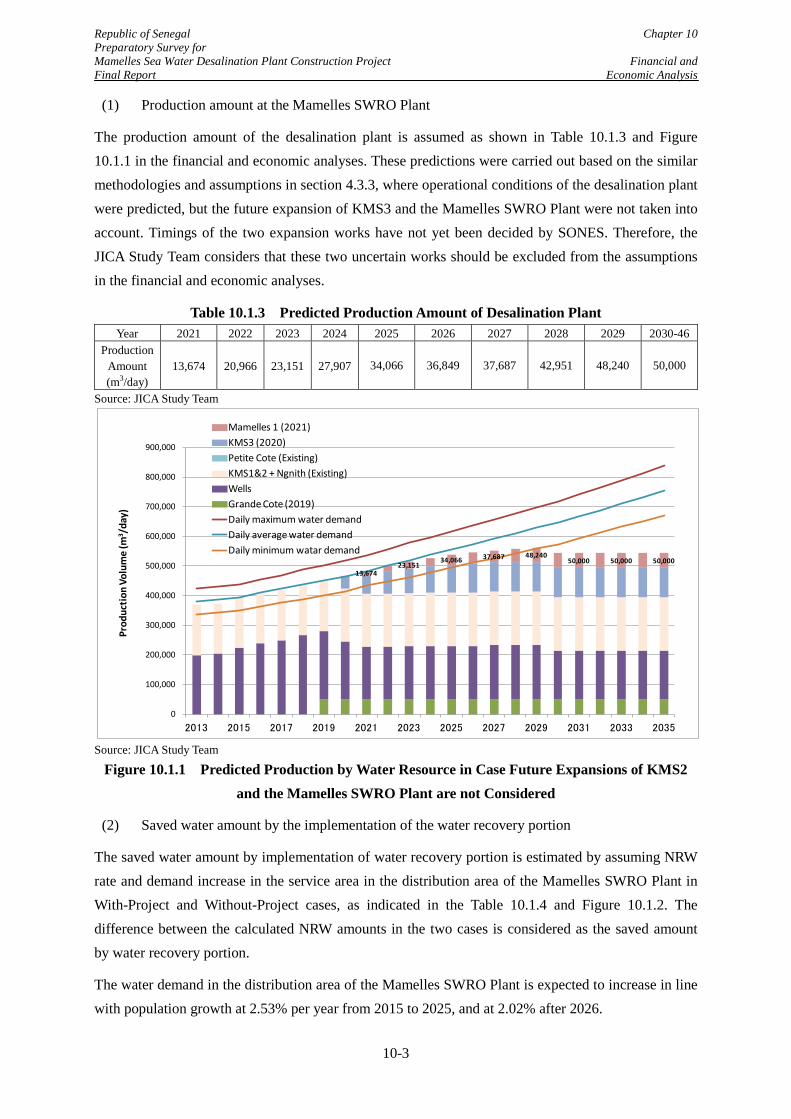
Republic of Senegal Chapter 10 Preparatory Survey for Mamelles Sea Water Desalination Plant Construction Project Financial and Final Report Economic Analysis
(1) Production amount at the Mamelles SWRO Plant
The production amount of the desalination plant is assumed as shown in Table 10.1.3 and Figure 10.1.1 in the financial and economic analyses. These predictions were carried out based on the similar methodologies and assumptions in section 4.3.3, where operational conditions of the desalination plant were predicted, but the future expansion of KMS3 and the Mamelles SWRO Plant were not taken into account. Timings of the two expansion works have not yet been decided by SONES. Therefore, the JICA Study Team considers that these two uncertain works should be excluded from the assumptions in the financial and economic analyses.
Table 10.1.3 Predicted Production Amount of Desalination Plant Year 2021 2022 2023 2024 2025 2026 2027 2028 2029 2030-46
Production Amount (m3/day)
13,674 20,966 23,151 27,907 34,066 36,849 37,687 42,951 48,240 50,000
Source: JICA Study Team
Source: JICA Study Team
Figure 10.1.1 Predicted Production by Water Resource in Case Future Expansions of KMS2 and the Mamelles SWRO Plant are not Considered
(2) Saved water amount by the implementation of the water recovery portion
The saved water amount by implementation of water recovery portion is estimated by assuming NRW rate and demand increase in the service area in the distribution area of the Mamelles SWRO Plant in With-Project and Without-Project cases, as indicated in the Table 10.1.4 and Figure 10.1.2. The difference between the calculated NRW amounts in the two cases is considered as the saved amount by water recovery portion.
The water demand in the distribution area of the Mamelles SWRO Plant is expected to increase in line with population growth at 2.53% per year from 2015 to 2025, and at 2.02% after 2026.
13,674 23,151
34,066 37,687 48,240 50,000 50,000 50,000
0
100,000
200,000
300,000
400,000
500,000
600,000
700,000
800,000
900,000
2013 2015 2017 2019 2021 2023 2025 2027 2029 2031 2033 2035
Prod
uctio
n Vo
lum
e (m
3 /da
y)
Mamelles 1 (2021)KMS3 (2020)Petite Cote (Existing)KMS1&2 + Ngnith (Existing)WellsGrande Cote (2019)Daily maximum water demandDaily average water demandDaily minimum watar demand
10-3
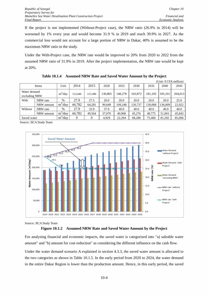
Republic of Senegal Chapter 10 Preparatory Survey for Mamelles Sea Water Desalination Plant Construction Project Financial and Final Report Economic Analysis
If the project is not implemented (Without-Project case), the NRW ratio (26.9% in 2014) will be worsened by 1% every year and would become 31.9 % in 2019 and reach 39.9% in 2027. As the commercial loss would not account for a large portion of NRW in Dakar, 40% is assumed to be the maximum NRW ratio in the study.
Under the With-Project case, the NRW rate would be improved to 20% from 2020 to 2022 from the assumed NRW ratio of 31.9% in 2019. After the project implementation, the NRW rate would be kept at 20%.
Table 10.1.4 Assumed NRW Rate and Saved Water Amount by the Project (Unit: F.CFA million)
Items Unit 2014 2015 2020 2025 2030 2035 2040 2043
Water demand excluding NRW
m3/day 112,646 115.496 130,865 148,278 163,872 181,105 195,101 204,013
With NRW rate % 27.9 27.5 20.0 20.0 20.0 20.0 20.0 25.0 NRW amount m3/day 44,782 64,281 90,649 109,248 120,737 130,068 136,009 22,922
Without NRW rate % 27.9 32.9 37.9 40.0 40.0 40.0 40.0 40.0 NRW amount m3/day 44,782 49,564 37,070 40,968 45,276 48,775 51,003 45,843
Saved water m3/day 0 0 4,929 22,294 68,280 75,460 81,292 85,006 Source: JICA Study Team
Source: JICA Study Team
Figure 10.1.2 Assumed NRW Rate and Saved Water Amount by the Project
For analysing financial and economic impacts, the saved water is categorized into "a) saleable water amount" and "b) amount for cost reduction" as considering the different influence on the cash flow.
Under the water demand scenario A explained in section 4.3.3, the saved water amount is allocated to the two categories as shown in Table 10.1.5. In the early period from 2020 to 2024, the water demand in the entire Dakar Region is lower than the production amount. Hence, in this early period, the saved
31.9 32.9
33.9 34.9
35.9 36.9
31.9 29.5
27.0 25.0 25.0 25.0 25.0 25.0 25.0
0.0
5.0
10.0
15.0
20.0
25.0
30.0
35.0
40.0
45.0
0
50,000
100,000
150,000
200,000
250,000
300,000
350,000
2019 2020 2021 2022 2023 2024 2025 2026 2027 2028 2029 2030 2031 2032 2033 2034 2035
NRW
rate
(%)
Wat
er A
mou
nt (
m3 /
day)
Water Demand (without Project)
Water Demand (with Project)
Water Demand(Excluding NRW)
NRW rate (without Project)
NRW rate (with Project)
Saved Water Amount
10-4
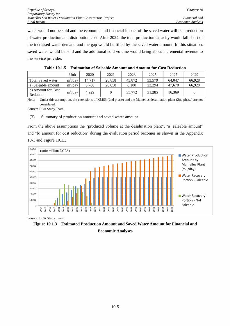
Republic of Senegal Chapter 10 Preparatory Survey for Mamelles Sea Water Desalination Plant Construction Project Financial and Final Report Economic Analysis
water would not be sold and the economic and financial impact of the saved water will be a reduction of water production and distribution cost. After 2024, the total production capacity would fall short of the increased water demand and the gap would be filled by the saved water amount. In this situation, saved water would be sold and the additional sold volume would bring about incremental revenue to the service provider.
Table 10.1.5 Estimation of Saleable Amount and Amount for Cost Reduction Unit 2020 2021 2023 2025 2027 2029
Total Saved water m3/day 14,717 28,858 43,872 53,579 64,047 66,928 a) Saleable amount m3/day 9,788 28,858 8,100 22,294 47,678 66,928 b) Amount for Cost Reduction m3/day 4,929 0 35,772 31,285 16,369 0
Note: Under this assumption, the extensions of KMS3 (2nd phase) and the Mamelles desalination plant (2nd phase) are not considered.
Source: JICA Study Team
(3) Summary of production amount and saved water amount
From the above assumptions the "produced volume at the desalination plant", "a) saleable amount" and "b) amount for cost reduction" during the evaluation period becomes as shown in the Appendix 10-1 and Figure 10.1.3.
Source: JICA Study Team
Figure 10.1.3 Estimated Production Amount and Saved Water Amount for Financial and Economic Analyses
0
10,000
20,000
30,000
40,000
50,000
60,000
70,000
80,000
90,000
100,000
2017
2018
2019
2020
2021
2022
2023
2024
2025
2026
2027
2028
2029
2030
2031
2032
2033
2034
2035
2036
2037
2038
2039
2040
2041
2042
2043
2044
2045
2046
Water Production Amount by Mamelles Plant (m3/day)
Water Recovery Portion - Saleable
Water Recovery Portion - Not Saleable
(unit: million F.CFA)
10-5
Republic of Senegal Chapter 10 Preparatory Survey for Mamelles Sea Water Desalination Plant Construction Project Financial and Final Report Economic Analysis
10.2 Financial Analysis
In this sub chapter, financial analysis is conducted to evaluate the financial viability of the Project.
The incremental revenue and cost induced by the project implementation are estimated based on the facility design and past construction records. Then, a discounted cash flow analysis is applied on the revenue and cost to convert the future values into the present value. As a result, Financial Internal Rate of Return (FIRR), Benefit Cost Ratio (B/C) and Net Present Value (NPV) are computed as the indicators of financial feasibility of the Project.
10.2.1 Outline of Financial Analysis
(1) Items of revenue and financial cost to be counted in the analysis
Table 10.2.1 Revenue and Cost Items Considered in the Financial Analysis Financial Revenue Financial Cost
- Incremental revenue derived from the water production portion
- Incremental revenue from the water recovery portion
- Initial construction cost - Additional O&M cost - Future replacement cost for equipment in the plant - Residual value at the end of the evaluation period - Reduction in maintenance cost of pipe network - Reduction in water production cost derived from the water
recovery portion Source: JICA Study Team
(2) Weighted Average Cost of Capital (WACC)
WACC is used as the discount rate for the financial analysis. WACC is calculated as a weighted average of the costs of capitals by the amounts from the respective financial sources such as Japanese ODA loan and the own fund of SONES.
Calculation of WACC of the Project is presented in Table 10.2.2. The calculation assumes that all eligible items will be covered by the Japanese ODA loan. Also, the calculation assumes that the whole ODA loan amount will be transferred to SONES from Ministry of Economy, Finance and Planning (MEFP) without adding any premium rate on the base interest rate of 0.7% from JICA to Government of Senegal (GOS). The cost of capital of the own finance of SONES is assumed at 0.0% as it is a public entity. As a result of the calculation, WACC is 0.64%.
Table 10.2.2 Fund Source and WACC of the Project Percentage* Fund Source Cost of Capital
Eligible Portion of ODA loan 92% ODA Loan 0.7%** Self financing by SONES 8% Self financing 0.0%
Total 100% 0.64% (WACC) * Share of each component is estimated based on the cost estimation of the eligible portion and non-eligible portion of
ODA loan. ** The condition of loan transfer from MEFP to SONES is not fixed. Source: JICA Study Team
10-6
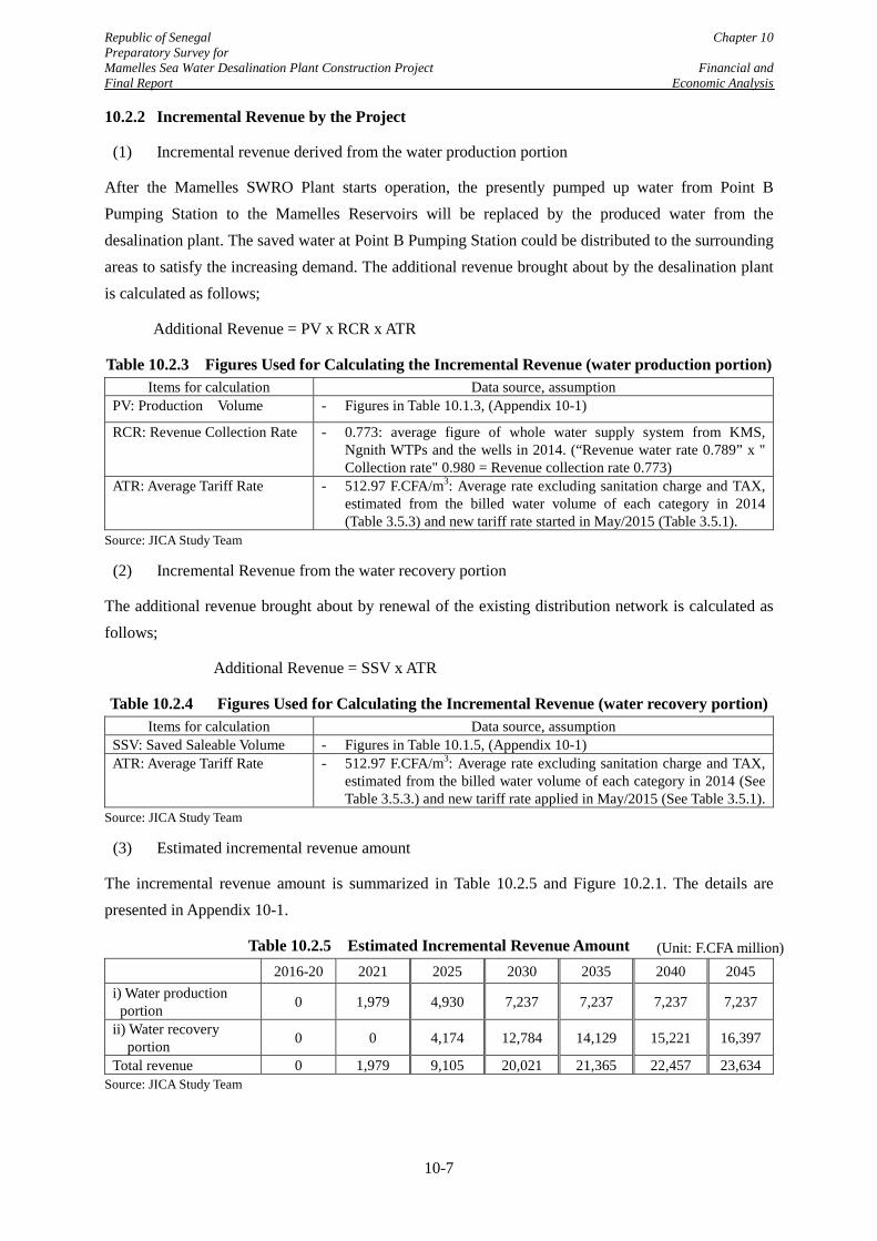
Republic of Senegal Chapter 10 Preparatory Survey for Mamelles Sea Water Desalination Plant Construction Project Financial and Final Report Economic Analysis
10.2.2 Incremental Revenue by the Project
(1) Incremental revenue derived from the water production portion
After the Mamelles SWRO Plant starts operation, the presently pumped up water from Point B Pumping Station to the Mamelles Reservoirs will be replaced by the produced water from the desalination plant. The saved water at Point B Pumping Station could be distributed to the surrounding areas to satisfy the increasing demand. The additional revenue brought about by the desalination plant is calculated as follows;
Additional Revenue = PV x RCR x ATR
Table 10.2.3 Figures Used for Calculating the Incremental Revenue (water production portion) Items for calculation Data source, assumption
PV: Production Volume - Figures in Table 10.1.3, (Appendix 10-1)
RCR: Revenue Collection Rate - 0.773: average figure of whole water supply system from KMS, Ngnith WTPs and the wells in 2014. (“Revenue water rate 0.789” x " Collection rate" 0.980 = Revenue collection rate 0.773)
ATR: Average Tariff Rate - 512.97 F.CFA/m3: Average rate excluding sanitation charge and TAX, estimated from the billed water volume of each category in 2014 (Table 3.5.3) and new tariff rate started in May/2015 (Table 3.5.1).
Source: JICA Study Team
(2) Incremental Revenue from the water recovery portion
The additional revenue brought about by renewal of the existing distribution network is calculated as follows;
Additional Revenue = SSV x ATR
Table 10.2.4 Figures Used for Calculating the Incremental Revenue (water recovery portion) Items for calculation Data source, assumption
SSV: Saved Saleable Volume - Figures in Table 10.1.5, (Appendix 10-1) ATR: Average Tariff Rate - 512.97 F.CFA/m3: Average rate excluding sanitation charge and TAX,
estimated from the billed water volume of each category in 2014 (See Table 3.5.3.) and new tariff rate applied in May/2015 (See Table 3.5.1).
Source: JICA Study Team
(3) Estimated incremental revenue amount
The incremental revenue amount is summarized in Table 10.2.5 and Figure 10.2.1. The details are presented in Appendix 10-1.
Table 10.2.5 Estimated Incremental Revenue Amount 2016-20 2021 2025 2030 2035 2040 2045
i) Water production portion 0 1,979 4,930 7,237 7,237 7,237 7,237
ii) Water recovery portion 0 0 4,174 12,784 14,129 15,221 16,397
Total revenue 0 1,979 9,105 20,021 21,365 22,457 23,634 Source: JICA Study Team
(Unit: F.CFA million)
10-7
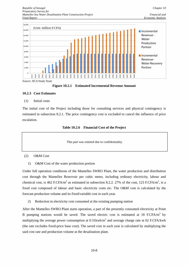
Republic of Senegal Chapter 10 Preparatory Survey for Mamelles Sea Water Desalination Plant Construction Project Financial and Final Report Economic Analysis
0
2,000
4,000
6,000
8,000
10,000
12,000
14,000
16,000
18,000
2017
2018
2019
2020
2021
2022
2023
2024
2025
2026
2027
2028
2029
2030
2031
2032
2033
2034
2035
2036
2037
2038
2039
2040
2041
2042
2043
2044
2045
2046
Incremental Revenue -Water Production Portion
Incremental Revenue -Water Recovery Portion
Source: JICA Study Team
Figure 10.2.1 Estimated Incremental Revenue Amount
10.2.3 Cost Estimates
(1) Initial costs
The initial cost of the Project including those for consulting services and physical contingency is estimated in subsection 8.2.1. The price contingency cost is excluded to cancel the influence of price escalation.
Table 10.2.6 Financial Cost of the Project
(2) O&M Cost
1) O&M Cost of the water production portion
Under full operation conditions of the Mamelles SWRO Plant, the water production and distribution cost through the Mamelles Reservoir per cubic meter, including ordinary electricity, labour and chemical cost, is 462 F.CFA/m3 as estimated in subsection 8.2.2. 27% of the cost, 123 F.CFA/m3, is a fixed cost composed of labour and basic electricity costs etc. The O&M cost is calculated by the forecast production volume and its fixed/variable cost in each year.
2) Reduction in electricity cost consumed at the existing pumping station
After the Mamelles SWRO Plant starts operation, a part of the presently consumed electricity at Point B pumping stations would be saved. The saved electric cost is estimated at 18 F.CFA/m3 by multiplying the average power consumption at 0.31kwh/m3 and average charge rate at 62 F.CFA/kwh (the rate excludes fixed-price base cost). The saved cost in each year is calculated by multiplying the said cost rate and production volume at the desalination plant.
(Unit: million F.CFA)
This part was omitted due to confidentiality.
10-8
Republic of Senegal Chapter 10 Preparatory Survey for Mamelles Sea Water Desalination Plant Construction Project Financial and Final Report Economic Analysis
3) Reduction in maintenance cost of pipe network
After the renewal of the existing distribution network, the frequency of claims and accidents relevant to pipelines would be reduced. In the study, the saved annual O&M cost is predicted to be 0.5% of the total investment cost for pipe renewal, from the past experience of pipe maintenance in the world.
4) Reduction in water production and distribution cost caused by the pipe renewal
Due to the pipe renewal, water loss from the deteriorated pipes would be reduced. From 2020 to 2024, the saved water would not be saleable as the water demand in the distribution area of the desalination plant is not enough to consume the saved water. Instead, the water production will be reduced during this period and the reduced cost for water production and distribution will have a positive impact on the cash flow;
Reduced Production and Distribution Cost = ACR x PCSW
Table 10.2.7 Figures Used for Calculating the Reduced Cost by the Project Items for calculation Assumption and data source
ACR: Amount for Cost Reduction - As shown in the Table 10.1.5, (Appendix 10-1)
PCSW: Production and Distribution Cost per Sold Water
- 198.72 F.CFA/m3 : estimated by the financial report of SDE in 2014 - SDE's variable cost for O&M (F.CFA 26,088 million including energy
cost, material cost and chemical cost) is divided by actual sold water amount in 2014 (131,281,610 m3)
Source: JICA Study Team
(3) Replacement cost
The life period of the mechanical & electrical equipment portion and the civil & architecture facility portion is assumed to be 20 years and 50 years, respectively. 40% of the mechanical & electrical equipment portion (63% of water production portion) excluding membranes cost (F.CFA 2,150 million) is assumed to be replaced after 20 years of commencement of the operation (in 25th year).
(4) Residual value at the end of the evaluation period
The residual value of the desalination plant and renewed pipes are added as the revenue in the final year.
(5) Total financial cost
Details of the above costs are indicated in the Appendix 10-1 and Figure 10.2.2. The O&M cost the SWRO plant takes a comparatively higher share.
10-9
Republic of Senegal Chapter 10 Preparatory Survey for Mamelles Sea Water Desalination Plant Construction Project Financial and Final Report Economic Analysis
Figure 10.2.2 Financial Cost of the Project
10.2.4 Result of Financial Analysis
From the incremental revenue and costs estimated above, FIRR of the Project becomes 5.6% and NPV becomes F.CFA 160,676 million. FIRR of the Project surpluses the WACC rate at 0.64%. and these figures indicate a high financial viability of the Project even under the present tariff level.
Table 10.2.8 Result of Financial Analysis FIRR NPV
(i) Desalination plant portion -9.2 % - F.CFA 92,154 million (ii) Pipe Rehabilitation portion 13.6 % F.CFA 252,830 million Whole Project 5.6 % F.CFA 160,676 million
Source: JICA Study Team
Furthermore, FIRR and NPV using increased water tariff up to the affordable level of the users are simulated. The affordable level for water supply charge is generally estimated as a percentage against total income of the household. Among most bilateral and international donors, 5% of the total household incomes are commonly considered as the maximum affordable level of the households for water and sanitation charge.. In the Study, the water charge, as the affordable limit of the water tariff, is set at approximately 4% of the average household income excluding the sanitation charge (approximately 1.0%). The tariff level is set at 805.36 F.CFA/m3, which is 57% above the present tariff level.
After adopting the affordability to pay rate on the revenue estimation, the FIRR of the project becomes 10.4% and NPV (Net Present Value) becomes F.CFA 395,283 million as shown in the Table 10.2.9 and Appendix 10-2.
This part was omitted due to confidentiality.
10-10
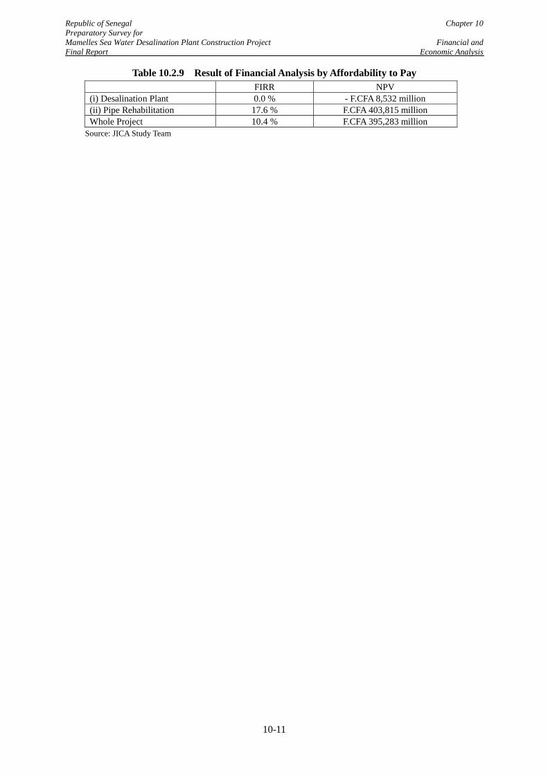
Republic of Senegal Chapter 10 Preparatory Survey for Mamelles Sea Water Desalination Plant Construction Project Financial and Final Report Economic Analysis
Table 10.2.9 Result of Financial Analysis by Affordability to Pay FIRR NPV
(i) Desalination Plant 0.0 % - F.CFA 8,532 million (ii) Pipe Rehabilitation 17.6 % F.CFA 403,815 million Whole Project 10.4 % F.CFA 395,283 million
Source: JICA Study Team
10-11
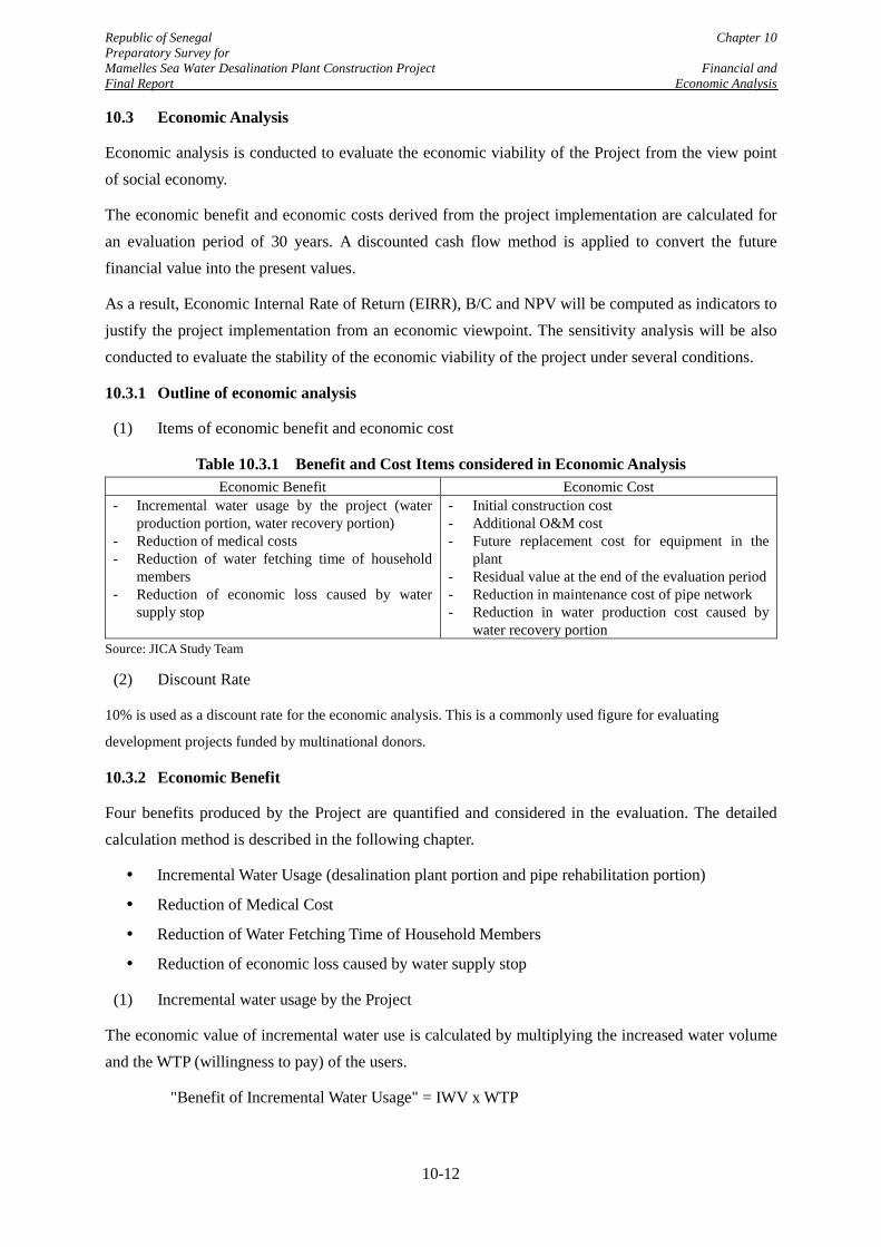
Republic of Senegal Chapter 10 Preparatory Survey for Mamelles Sea Water Desalination Plant Construction Project Financial and Final Report Economic Analysis
10.3 Economic Analysis
Economic analysis is conducted to evaluate the economic viability of the Project from the view point of social economy.
The economic benefit and economic costs derived from the project implementation are calculated for an evaluation period of 30 years. A discounted cash flow method is applied to convert the future financial value into the present values.
As a result, Economic Internal Rate of Return (EIRR), B/C and NPV will be computed as indicators to justify the project implementation from an economic viewpoint. The sensitivity analysis will be also conducted to evaluate the stability of the economic viability of the project under several conditions.
10.3.1 Outline of economic analysis
(1) Items of economic benefit and economic cost
Table 10.3.1 Benefit and Cost Items considered in Economic Analysis Economic Benefit Economic Cost
- Incremental water usage by the project (water production portion, water recovery portion)
- Reduction of medical costs - Reduction of water fetching time of household
members - Reduction of economic loss caused by water
supply stop
- Initial construction cost - Additional O&M cost - Future replacement cost for equipment in the
plant - Residual value at the end of the evaluation period - Reduction in maintenance cost of pipe network - Reduction in water production cost caused by
water recovery portion Source: JICA Study Team
(2) Discount Rate
10% is used as a discount rate for the economic analysis. This is a commonly used figure for evaluating
development projects funded by multinational donors.
10.3.2 Economic Benefit
Four benefits produced by the Project are quantified and considered in the evaluation. The detailed calculation method is described in the following chapter.
Incremental Water Usage (desalination plant portion and pipe rehabilitation portion)
Reduction of Medical Cost
Reduction of Water Fetching Time of Household Members
Reduction of economic loss caused by water supply stop
(1) Incremental water usage by the Project
The economic value of incremental water use is calculated by multiplying the increased water volume and the WTP (willingness to pay) of the users.
"Benefit of Incremental Water Usage" = IWV x WTP
10-12
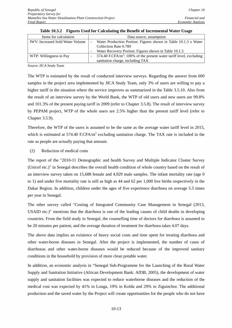
Republic of Senegal Chapter 10 Preparatory Survey for Mamelles Sea Water Desalination Plant Construction Project Financial and Final Report Economic Analysis
Table 10.3.2 Figures Used for Calculating the Benefit of Incremental Water Usage Items for calculation Data source, assumption
IWV: Increased Sold Water Volume - Water Production Portion: Figures shown in Table 10.1.3 x Water Collection Rate 0.789
- Water Recovery Portion: Figures shown in Table 10.1.5 WTP: Willingness to Pay - 574.40 F.CFA/m3: 100% of the present water tariff level, excluding
sanitation charge, including TAX Source: JICA Study Team
The WTP is estimated by the result of conducted interview surveys. Regarding the answer from 600 samples in the project area implemented by JICA Study Team, only 3% of users are willing to pay a higher tariff in the situation where the service improves as summarized in the Table 3.5.10. Also from the result of an interview survey by the World Bank, the WTP of old users and new users are 99.8% and 101.3% of the present paying tariff in 2009 (refer to Chapter 3.5.8). The result of interview survey by PEPAM project, WTP of the whole users are 2.5% higher than the present tariff level (refer to Chapter 3.5.9).
Therefore, the WTP of the users is assumed to be the same as the average water tariff level in 2015, which is estimated at 574.40 F.CFA/m3 excluding sanitation charge. The TAX rate is included in the rate as people are actually paying that amount.
(2) Reduction of medical costs
The report of the "2010-11 Demographic and health Survey and Multiple Indicator Cluster Survey (Unicef etc.)" in Senegal describes the overall health condition of whole country based on the result of an interview survey taken on 15,688 female and 4,929 male samples. The infant mortality rate (age 0 to 1) and under five mortality rate is still as high as 44 and 62 per 1,000 live births respectively in the Dakar Region. In addition, children under the ages of five experience diarrhoea on average 5.5 times per year in Senegal.
The other survey called "Costing of Integrated Community Case Management in Senegal (2013, USAID etc.)" mentions that the diarrhoea is one of the leading causes of child deaths in developing countries. From the field study in Senegal, the counselling time of doctors for diarrhoea is assumed to be 20 minutes per patient, and the average duration of treatment for diarrhoea takes 4.07 days.
The above data implies an existence of heavy social costs and time spent for treating diarrhoea and other water-borne diseases in Senegal. After the project is implemented, the number of cases of diarrhoeas and other water-borne diseases would be reduced because of the improved sanitary conditions in the household by provision of more clean potable water.
In addition, an economic analysis in “Senegal Sub-Programme for the Launching of the Rural Water Supply and Sanitation Initiative (African Development Bank: AfDB, 2005), the development of water supply and sanitation facilities was expected to reduce waterborne diseases and the reduction of the medical cost was expected by 41% in Louga, 19% in Kolda and 29% in Ziguinchor. The additional production and the saved water by the Project will create opportunities for the people who do not have
10-13
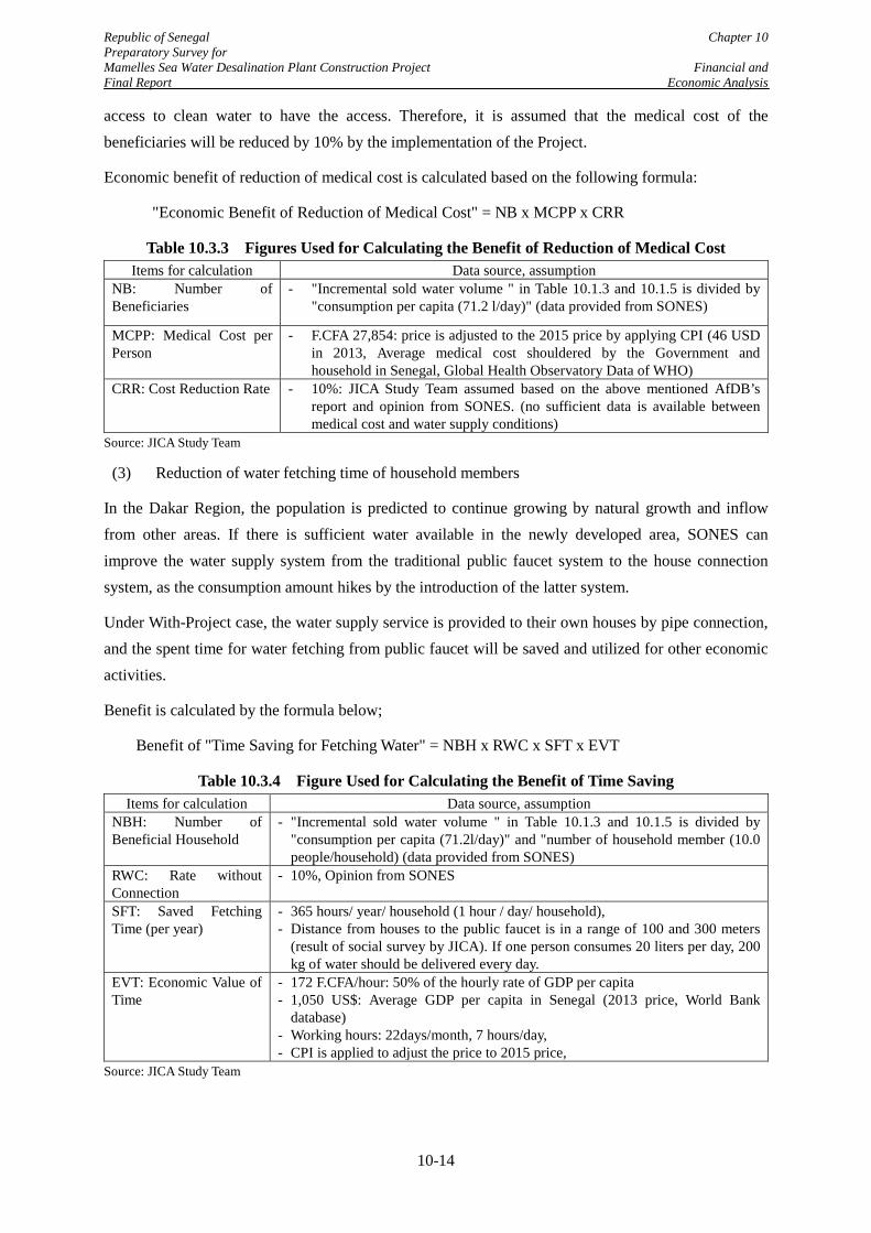
Republic of Senegal Chapter 10 Preparatory Survey for Mamelles Sea Water Desalination Plant Construction Project Financial and Final Report Economic Analysis
access to clean water to have the access. Therefore, it is assumed that the medical cost of the beneficiaries will be reduced by 10% by the implementation of the Project.
Economic benefit of reduction of medical cost is calculated based on the following formula:
"Economic Benefit of Reduction of Medical Cost" = NB x MCPP x CRR
Table 10.3.3 Figures Used for Calculating the Benefit of Reduction of Medical Cost Items for calculation Data source, assumption
NB: Number of Beneficiaries
- "Incremental sold water volume " in Table 10.1.3 and 10.1.5 is divided by "consumption per capita (71.2 l/day)" (data provided from SONES)
MCPP: Medical Cost per Person
- F.CFA 27,854: price is adjusted to the 2015 price by applying CPI (46 USD in 2013, Average medical cost shouldered by the Government and household in Senegal, Global Health Observatory Data of WHO)
CRR: Cost Reduction Rate - 10%: JICA Study Team assumed based on the above mentioned AfDB’s report and opinion from SONES. (no sufficient data is available between medical cost and water supply conditions)
Source: JICA Study Team
(3) Reduction of water fetching time of household members
In the Dakar Region, the population is predicted to continue growing by natural growth and inflow from other areas. If there is sufficient water available in the newly developed area, SONES can improve the water supply system from the traditional public faucet system to the house connection system, as the consumption amount hikes by the introduction of the latter system.
Under With-Project case, the water supply service is provided to their own houses by pipe connection, and the spent time for water fetching from public faucet will be saved and utilized for other economic activities.
Benefit is calculated by the formula below;
Benefit of "Time Saving for Fetching Water" = NBH x RWC x SFT x EVT
Table 10.3.4 Figure Used for Calculating the Benefit of Time Saving Items for calculation Data source, assumption
NBH: Number of Beneficial Household
- "Incremental sold water volume " in Table 10.1.3 and 10.1.5 is divided by "consumption per capita (71.2l/day)" and "number of household member (10.0 people/household) (data provided from SONES)
RWC: Rate without Connection
- 10%, Opinion from SONES
SFT: Saved Fetching Time (per year)
- 365 hours/ year/ household (1 hour / day/ household), - Distance from houses to the public faucet is in a range of 100 and 300 meters
(result of social survey by JICA). If one person consumes 20 liters per day, 200 kg of water should be delivered every day.
EVT: Economic Value of Time
- 172 F.CFA/hour: 50% of the hourly rate of GDP per capita - 1,050 US$: Average GDP per capita in Senegal (2013 price, World Bank
database) - Working hours: 22days/month, 7 hours/day, - CPI is applied to adjust the price to 2015 price,
Source: JICA Study Team
10-14
Republic of Senegal Chapter 10 Preparatory Survey for Mamelles Sea Water Desalination Plant Construction Project Financial and Final Report Economic Analysis
The average GDP per capita in Senegal is USD 1,050 in 2013 referring to the World Bank database. This amount is divided by annual working hours (12 month x 22 days x 7 hours), the hourly salary is estimated at F.CFA 344 after adopting CPI to adjust to 2015 price. In the study, 50% of the saved time is assumed to be used for other income generating activity considering the work opportunity in the area.
(4) Reduction of economic loss caused by water supply stop
The Dakar Region depends major water resource on the Guiers lake, and the past breakage accident in the main transmission pipe caused a 3-week suspension of the water supply services in 2013. In economic analyses of water supply projects, it is not common to take into account the benefit by mitigating the risk of economic loss caused by such suspensions of the water supply services. As the mitigation of the service suspension risk, by improving the water resource diversity, is one of the main objectives of the Project, the Study implement a quantification of such benefit that will be derived from the Project.
Methodology of the benefit quantification follows a Japanese manual named “Manual on Cost-Benefit Analysis fir Water Supply Projects” , Volume V Appendix (July/2011, Ministry of Health, Labour and Welfare in Japan)” (hereinafter, “Cost-Benefit Manual”). Japan frequently faces earthquakes, thereby accumulated knowledge and analysis methodologies for evaluation of economic losses by suspension of water supply services have been established. Therefore, JICA Study Team views that the Japanese manual is the reliable reference in the quantification of the benefit by mitigating the risk of the suspension of the water supply services.
In the Cost-Benefit Manual, the following three items are to be evaluated:
(1) Reduction of Economic Loss of Business Entities
(2) Reduction of cost of users (procurement cost of tank/bottles etc.)
(3) Reduction of cost of service provider (cost for public information, tanker service, etc.)
In the Study, the “(1) Reduction of Economic Loss of Business Entities” is quantified as it has the highest benefit. On the other hand, the other two benefits are not quantified in the Study because reliable data for the evaluations are not available.
According to the Cost-Benefit Manual, if the water supply services are suspended completely, the business activities for which water is inevitable will not be operational. Incomes in the other business will be reduced by 16%.
In Senegal, referring to the World Development Indicators of the World Bank, the industrial composition is 17.5% of agriculture sector, 24.0% of manufacturing sector and 58.3% of service sector. The service sector has relatively larger share compared with the other African countries. Due to the high share of the service sector, whose operation is subject to the water availability, the Study assumes that 50% of the total income in the country will be lost by the complete suspension of the water supply services.
10-15
Republic of Senegal Chapter 10 Preparatory Survey for Mamelles Sea Water Desalination Plant Construction Project Financial and Final Report Economic Analysis
0
2,000
4,000
6,000
8,000
10,000
12,000
14,000
16,000
18,000
20,000
2,01
7
2,01
8
2,01
9
2,02
0
2,02
1
2,02
2
2,02
3
2,02
4
2,02
5
2,02
6
2,02
7
2,02
8
2,02
9
2,03
0
2,03
1
2,03
2
2,03
3
2,03
4
2,03
5
2,03
6
2,03
7
2,03
8
2,03
9
2,04
0
2,04
1
2,04
2
2,04
3
2,04
4
2,04
5
2,04
6
Incremental Production - Water Production PortionIncremental Production - Water Recovery PortionReduction of Medical Cost
Time saved for Water Fetching
Prevention of Water Stop
As for the duration and frequency of the water supply suspension, 3-week suspension in every 10 year is assumed considering that the accident in 2013, which caused the 3-week suspension, happened five year later after completion of the water transmission pipe.
Based on the assumptions above, the benefit by reduction of economic loss by suspension of the water supply services is calculated by the following formula:
“Reduction of Economic Loss of Business Entities” = NB x DGDPPC x IR x AOD
Table 10.3.5 Figures Used for Calculation of the Benefit by Reduction of Economic Loss by Suspension of the Water Supply Service
Items for calculation Data source, assumption NB: Number of Beneficiaries 554,073 people: “Maximum production capacity (50,000m3/day) is
divided by “average daily consumption (71.2l/day)” and “average number of people per connection (10 people/connection)” (data from SONES)
DGDPPC: Daily GDP per Capita 334 F.CFA: adjusted at 2015 price by CPI (calculated in 10.3.2(3)) IR: Impact Rate 50%: Assumed by JICA study team following to manual AAOD : Annual Average Occurrence Days
2.1 days/year: Water stop for 3 weeks occurs every 10 years
Source: JICA Study Team
(5) Result of calculation
The estimated amount of each economic benefit is shown in the Appendix 10-3 and Figure 10.3.1.
Source: JICA Study Team
Figure 10.3.1 Economic Benefits of the Project
10.3.3 Economic Cost
Economic cost is calculated by extracting TAX from the cost estimation of the financial analysis. Then, the standard conversion factor (SCF) of 0.91 is multiplied on the domestic currency portion of the project cost.
1 Commonly used SCF rate in developing countries including Senegal
(unit: F. CFA million)
10-16
Republic of Senegal Chapter 10 Preparatory Survey for Mamelles Sea Water Desalination Plant Construction Project Financial and Final Report Economic Analysis
(1) Initial construction cost
The economic cost of initial construction cost become as shown in the Table 10.3.6 converting from the financial cost.
Table 10.3.6 Economic Cost of the Project
(2) Other Cost (O&M cost, replacement cost, residual value)
The economic cost (O&M work, replacement cost, residual value) are as shown in the Appendix 10-3 converting from the financial cost. Future replacement cost and residual value is assumed to be the same as the financial analysis.
(3) Total Economic Cost
The total economic cost is shown in the Figure 10.3.2.
Figure 10.3.2 Economic Costs of the Project
10.3.4 Result of Economic Analysis
From the estimated benefit and cost above, the EIRR of the project is calculated at 10.2 % and NPV (Net Present Value) is calculated at F.CFA 1,845 million with the discount rate of 10%. The EIRR is higher than 10% which is general standard value in bilateral and international donors in evaluation of the economic viability.
This part was omitted due to confidentiality.
This part was omitted due to confidentiality.
10-17
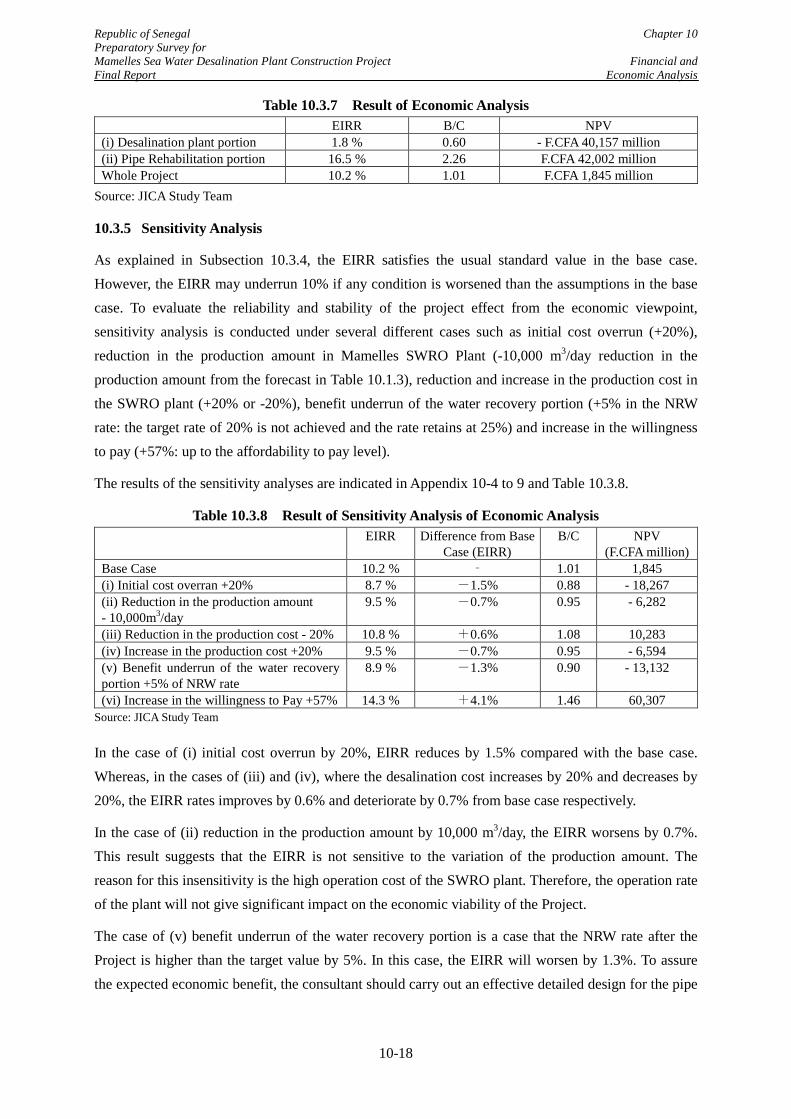
Republic of Senegal Chapter 10 Preparatory Survey for Mamelles Sea Water Desalination Plant Construction Project Financial and Final Report Economic Analysis
Table 10.3.7 Result of Economic Analysis EIRR B/C NPV
(i) Desalination plant portion 1.8 % 0.60 - F.CFA 40,157 million (ii) Pipe Rehabilitation portion 16.5 % 2.26 F.CFA 42,002 million Whole Project 10.2 % 1.01 F.CFA 1,845 million
Source: JICA Study Team
10.3.5 Sensitivity Analysis
As explained in Subsection 10.3.4, the EIRR satisfies the usual standard value in the base case. However, the EIRR may underrun 10% if any condition is worsened than the assumptions in the base case. To evaluate the reliability and stability of the project effect from the economic viewpoint, sensitivity analysis is conducted under several different cases such as initial cost overrun (+20%), reduction in the production amount in Mamelles SWRO Plant (-10,000 m3/day reduction in the production amount from the forecast in Table 10.1.3), reduction and increase in the production cost in the SWRO plant (+20% or -20%), benefit underrun of the water recovery portion (+5% in the NRW rate: the target rate of 20% is not achieved and the rate retains at 25%) and increase in the willingness to pay (+57%: up to the affordability to pay level).
The results of the sensitivity analyses are indicated in Appendix 10-4 to 9 and Table 10.3.8.
Table 10.3.8 Result of Sensitivity Analysis of Economic Analysis EIRR Difference from Base
Case (EIRR) B/C NPV
(F.CFA million) Base Case 10.2 % ‐ 1.01 1,845 (i) Initial cost overran +20% 8.7 % -1.5% 0.88 - 18,267 (ii) Reduction in the production amount - 10,000m3/day
9.5 % -0.7% 0.95 - 6,282
(iii) Reduction in the production cost - 20% 10.8 % +0.6% 1.08 10,283 (iv) Increase in the production cost +20% 9.5 % -0.7% 0.95 - 6,594 (v) Benefit underrun of the water recovery portion +5% of NRW rate
8.9 % -1.3% 0.90 - 13,132
(vi) Increase in the willingness to Pay +57% 14.3 % +4.1% 1.46 60,307 Source: JICA Study Team
In the case of (i) initial cost overrun by 20%, EIRR reduces by 1.5% compared with the base case. Whereas, in the cases of (iii) and (iv), where the desalination cost increases by 20% and decreases by 20%, the EIRR rates improves by 0.6% and deteriorate by 0.7% from base case respectively.
In the case of (ii) reduction in the production amount by 10,000 m3/day, the EIRR worsens by 0.7%. This result suggests that the EIRR is not sensitive to the variation of the production amount. The reason for this insensitivity is the high operation cost of the SWRO plant. Therefore, the operation rate of the plant will not give significant impact on the economic viability of the Project.
The case of (v) benefit underrun of the water recovery portion is a case that the NRW rate after the Project is higher than the target value by 5%. In this case, the EIRR will worsen by 1.3%. To assure the expected economic benefit, the consultant should carry out an effective detailed design for the pipe
10-18
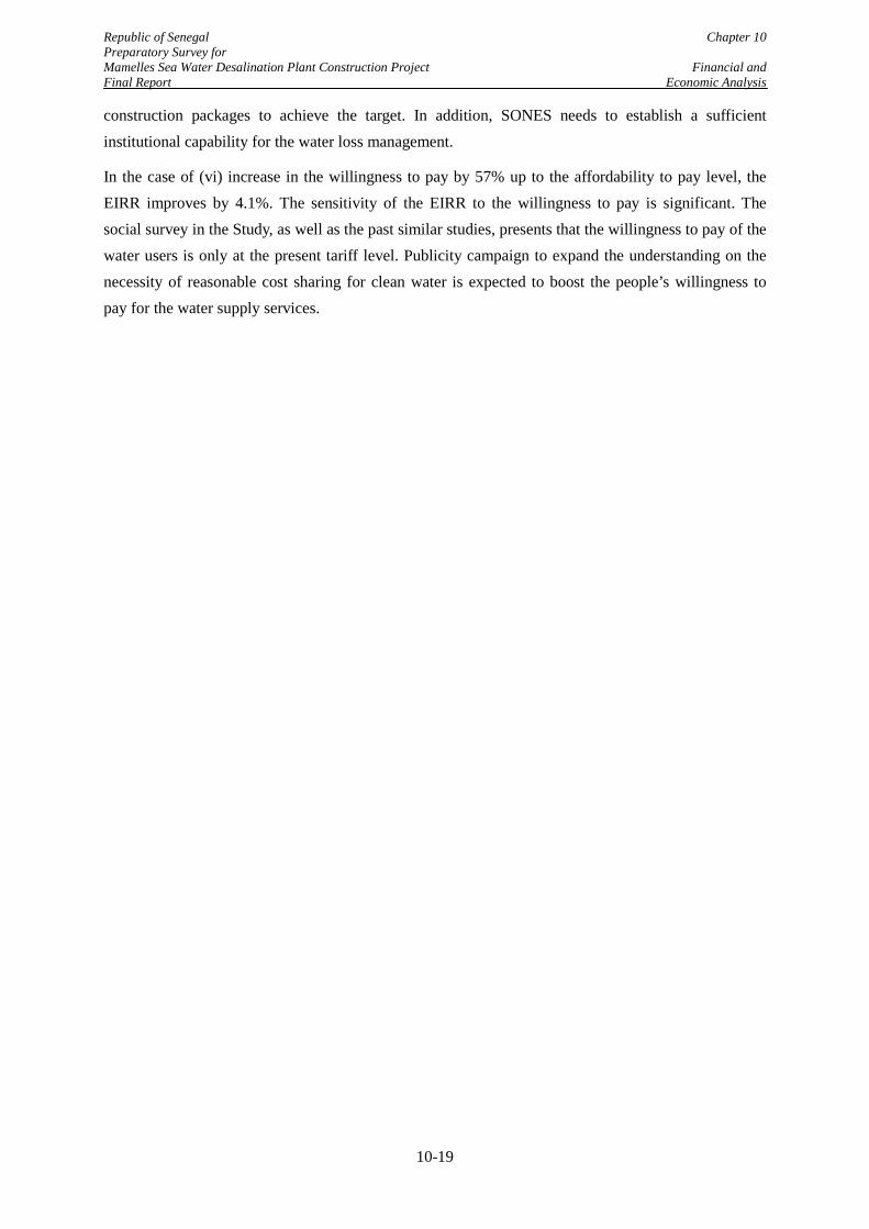
Republic of Senegal Chapter 10 Preparatory Survey for Mamelles Sea Water Desalination Plant Construction Project Financial and Final Report Economic Analysis
construction packages to achieve the target. In addition, SONES needs to establish a sufficient institutional capability for the water loss management.
In the case of (vi) increase in the willingness to pay by 57% up to the affordability to pay level, the EIRR improves by 4.1%. The sensitivity of the EIRR to the willingness to pay is significant. The social survey in the Study, as well as the past similar studies, presents that the willingness to pay of the water users is only at the present tariff level. Publicity campaign to expand the understanding on the necessity of reasonable cost sharing for clean water is expected to boost the people’s willingness to pay for the water supply services.
10-19
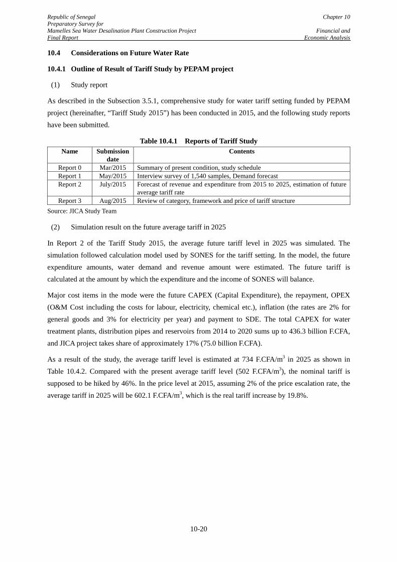
Republic of Senegal Chapter 10 Preparatory Survey for Mamelles Sea Water Desalination Plant Construction Project Financial and Final Report Economic Analysis
10.4 Considerations on Future Water Rate
10.4.1 Outline of Result of Tariff Study by PEPAM project
(1) Study report
As described in the Subsection 3.5.1, comprehensive study for water tariff setting funded by PEPAM project (hereinafter, “Tariff Study 2015”) has been conducted in 2015, and the following study reports have been submitted.
Table 10.4.1 Reports of Tariff Study Name Submission
date Contents
Report 0 Mar/2015 Summary of present condition, study schedule Report 1 May/2015 Interview survey of 1,540 samples, Demand forecast Report 2 July/2015 Forecast of revenue and expenditure from 2015 to 2025, estimation of future
average tariff rate Report 3 Aug/2015 Review of category, framework and price of tariff structure
Source: JICA Study Team
(2) Simulation result on the future average tariff in 2025
In Report 2 of the Tariff Study 2015, the average future tariff level in 2025 was simulated. The simulation followed calculation model used by SONES for the tariff setting. In the model, the future expenditure amounts, water demand and revenue amount were estimated. The future tariff is calculated at the amount by which the expenditure and the income of SONES will balance.
Major cost items in the mode were the future CAPEX (Capital Expenditure), the repayment, OPEX (O&M Cost including the costs for labour, electricity, chemical etc.), inflation (the rates are 2% for general goods and 3% for electricity per year) and payment to SDE. The total CAPEX for water treatment plants, distribution pipes and reservoirs from 2014 to 2020 sums up to 436.3 billion F.CFA, and JICA project takes share of approximately 17% (75.0 billion F.CFA).
As a result of the study, the average tariff level is estimated at 734 F.CFA/m3 in 2025 as shown in Table 10.4.2. Compared with the present average tariff level (502 F.CFA/m3), the nominal tariff is supposed to be hiked by 46%. In the price level at 2015, assuming 2% of the price escalation rate, the average tariff in 2025 will be 602.1 F.CFA/m3, which is the real tariff increase by 19.8%.
10-20
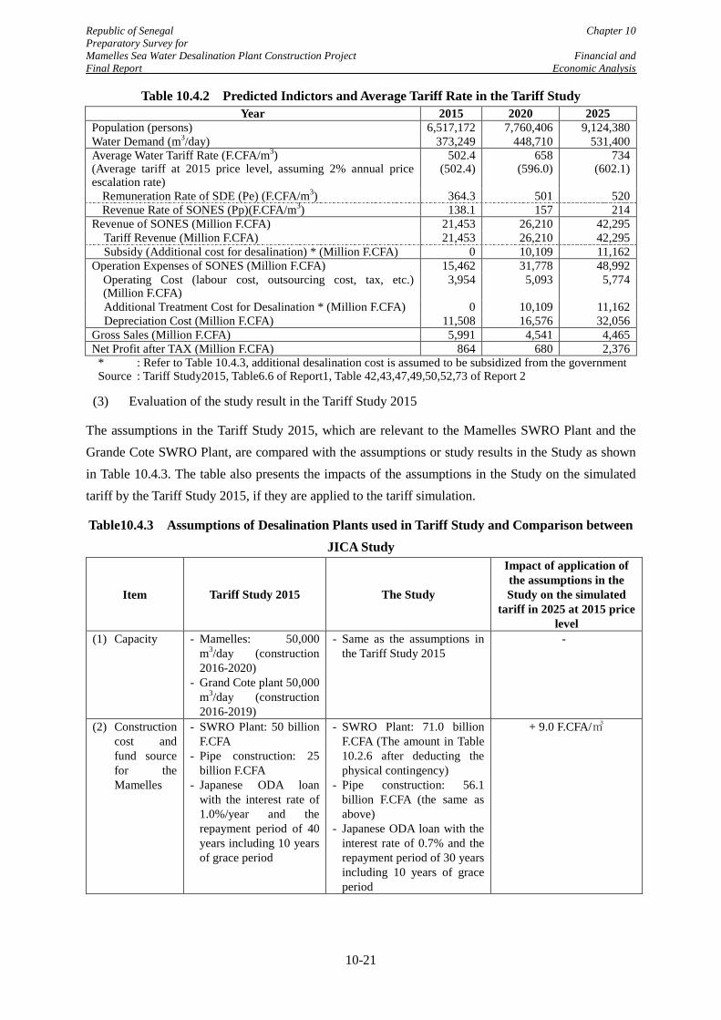
Republic of Senegal Chapter 10 Preparatory Survey for Mamelles Sea Water Desalination Plant Construction Project Financial and Final Report Economic Analysis
Table 10.4.2 Predicted Indictors and Average Tariff Rate in the Tariff Study Year 2015 2020 2025
Population (persons) 6,517,172 7,760,406 9,124,380 Water Demand (m3/day) 373,249 448,710 531,400 Average Water Tariff Rate (F.CFA/m3) (Average tariff at 2015 price level, assuming 2% annual price escalation rate)
502.4 (502.4)
658 (596.0)
734 (602.1)
Remuneration Rate of SDE (Pe) (F.CFA/m3) 364.3 501 520 Revenue Rate of SONES (Pp)(F.CFA/m3) 138.1 157 214
Revenue of SONES (Million F.CFA) 21,453 26,210 42,295 Tariff Revenue (Million F.CFA) 21,453 26,210 42,295 Subsidy (Additional cost for desalination) * (Million F.CFA) 0 10,109 11,162
Operation Expenses of SONES (Million F.CFA) 15,462 31,778 48,992 Operating Cost (labour cost, outsourcing cost, tax, etc.) (Million F.CFA)
3,954 5,093 5,774
Additional Treatment Cost for Desalination * (Million F.CFA) 0 10,109 11,162 Depreciation Cost (Million F.CFA) 11,508 16,576 32,056 Gross Sales (Million F.CFA) 5,991 4,541 4,465 Net Profit after TAX (Million F.CFA) 864 680 2,376
* : Refer to Table 10.4.3, additional desalination cost is assumed to be subsidized from the government Source : Tariff Study2015, Table6.6 of Report1, Table 42,43,47,49,50,52,73 of Report 2
(3) Evaluation of the study result in the Tariff Study 2015
The assumptions in the Tariff Study 2015, which are relevant to the Mamelles SWRO Plant and the Grande Cote SWRO Plant, are compared with the assumptions or study results in the Study as shown in Table 10.4.3. The table also presents the impacts of the assumptions in the Study on the simulated tariff by the Tariff Study 2015, if they are applied to the tariff simulation.
Table10.4.3 Assumptions of Desalination Plants used in Tariff Study and Comparison between JICA Study
Item Tariff Study 2015 The Study
Impact of application of the assumptions in the Study on the simulated
tariff in 2025 at 2015 price level
(1) Capacity - Mamelles: 50,000 m3/day (construction 2016-2020)
- Grand Cote plant 50,000 m3/day (construction 2016-2019)
- Same as the assumptions in the Tariff Study 2015
-
(2) Construction cost and fund source for the Mamelles
- SWRO Plant: 50 billion F.CFA
- Pipe construction: 25 billion F.CFA
- Japanese ODA loan with the interest rate of 1.0%/year and the repayment period of 40 years including 10 years of grace period
- SWRO Plant: 71.0 billion F.CFA (The amount in Table 10.2.6 after deducting the physical contingency)
- Pipe construction: 56.1 billion F.CFA (the same as above)
- Japanese ODA loan with the interest rate of 0.7% and the repayment period of 30 years including 10 years of grace period
+ 9.0 F.CFA/㎥
10-21
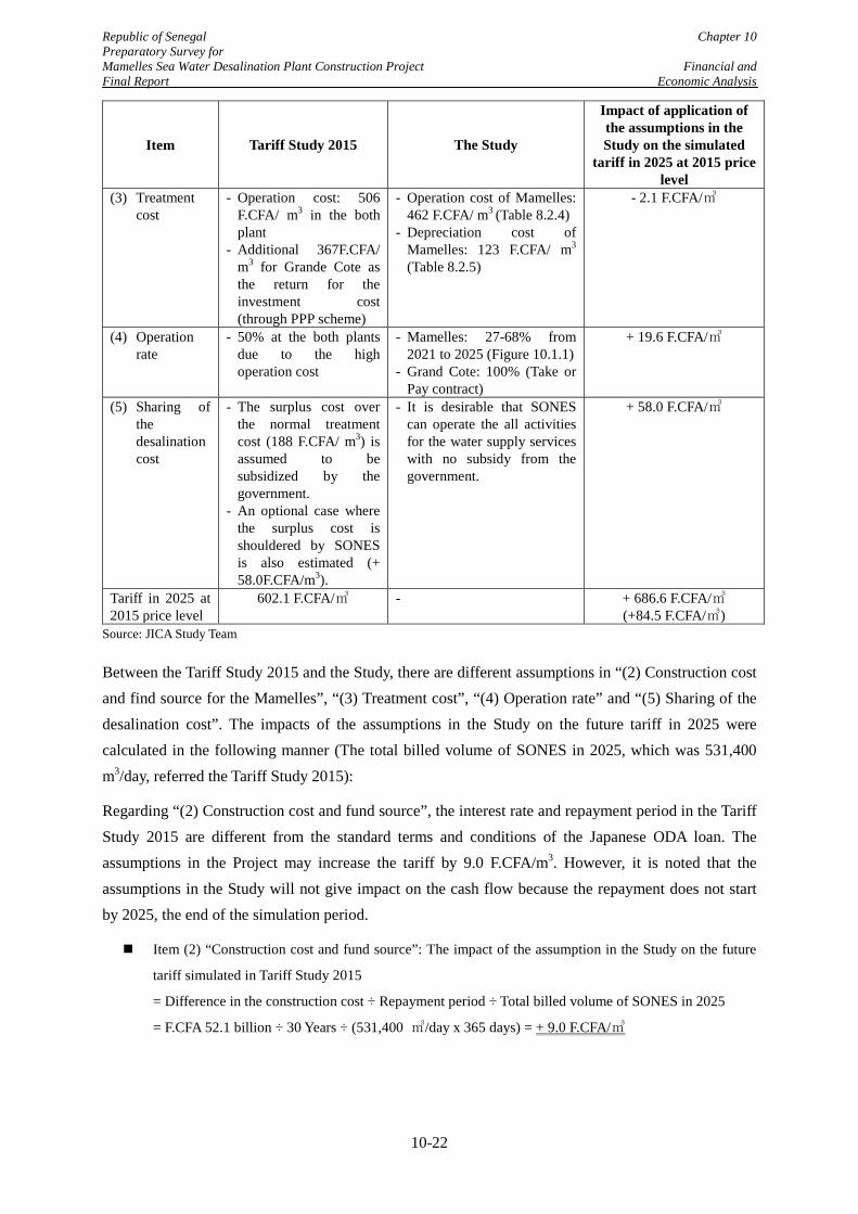
Republic of Senegal Chapter 10 Preparatory Survey for Mamelles Sea Water Desalination Plant Construction Project Financial and Final Report Economic Analysis
Item Tariff Study 2015 The Study
Impact of application of the assumptions in the Study on the simulated
tariff in 2025 at 2015 price level
(3) Treatment cost
- Operation cost: 506 F.CFA/ m3 in the both plant
- Additional 367F.CFA/ m3 for Grande Cote as the return for the investment cost (through PPP scheme)
- Operation cost of Mamelles: 462 F.CFA/ m3 (Table 8.2.4)
- Depreciation cost of Mamelles: 123 F.CFA/ m3
(Table 8.2.5)
- 2.1 F.CFA/㎥
(4) Operation rate
- 50% at the both plants due to the high operation cost
- Mamelles: 27-68% from 2021 to 2025 (Figure 10.1.1)
- Grand Cote: 100% (Take or Pay contract)
+ 19.6 F.CFA/㎥
(5) Sharing of the desalination cost
- The surplus cost over the normal treatment cost (188 F.CFA/ m3) is assumed to be subsidized by the government.
- An optional case where the surplus cost is shouldered by SONES is also estimated (+ 58.0F.CFA/m3).
- It is desirable that SONES can operate the all activities for the water supply services with no subsidy from the government.
+ 58.0 F.CFA/㎥
Tariff in 2025 at 2015 price level
602.1 F.CFA/㎥ - + 686.6 F.CFA/㎥ (+84.5 F.CFA/㎥)
Source: JICA Study Team
Between the Tariff Study 2015 and the Study, there are different assumptions in “(2) Construction cost and find source for the Mamelles”, “(3) Treatment cost”, “(4) Operation rate” and “(5) Sharing of the desalination cost”. The impacts of the assumptions in the Study on the future tariff in 2025 were calculated in the following manner (The total billed volume of SONES in 2025, which was 531,400 m3/day, referred the Tariff Study 2015):
Regarding “(2) Construction cost and fund source”, the interest rate and repayment period in the Tariff Study 2015 are different from the standard terms and conditions of the Japanese ODA loan. The assumptions in the Project may increase the tariff by 9.0 F.CFA/m3. However, it is noted that the assumptions in the Study will not give impact on the cash flow because the repayment does not start by 2025, the end of the simulation period.
Item (2) “Construction cost and fund source”: The impact of the assumption in the Study on the future
tariff simulated in Tariff Study 2015
= Difference in the construction cost ÷ Repayment period ÷ Total billed volume of SONES in 2025
= F.CFA 52.1 billion ÷ 30 Years ÷ (531,400 ㎥/day x 365 days) = + 9.0 F.CFA/㎥
10-22
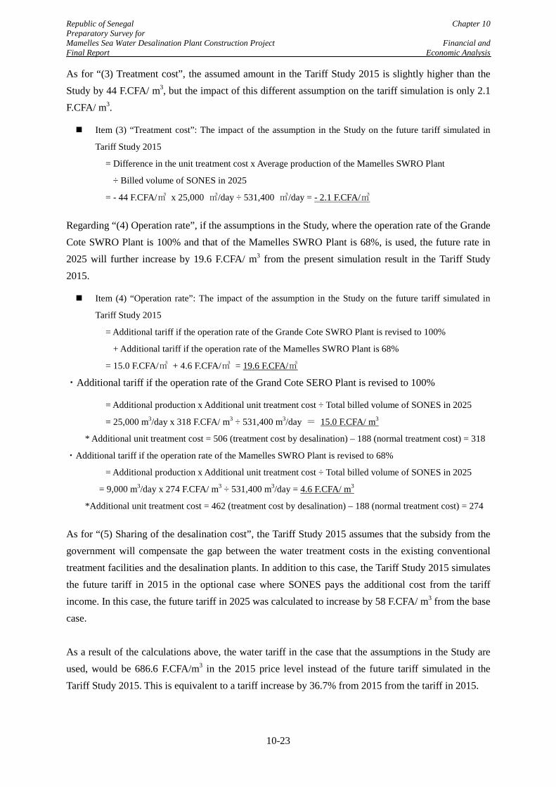
Republic of Senegal Chapter 10 Preparatory Survey for Mamelles Sea Water Desalination Plant Construction Project Financial and Final Report Economic Analysis
As for “(3) Treatment cost”, the assumed amount in the Tariff Study 2015 is slightly higher than the Study by 44 F.CFA/ m3, but the impact of this different assumption on the tariff simulation is only 2.1 F.CFA/ m3.
Item (3) “Treatment cost”: The impact of the assumption in the Study on the future tariff simulated in
Tariff Study 2015
= Difference in the unit treatment cost x Average production of the Mamelles SWRO Plant
÷ Billed volume of SONES in 2025
= - 44 F.CFA/㎥ x 25,000 ㎥/day ÷ 531,400 ㎥/day = - 2.1 F.CFA/㎥ Regarding “(4) Operation rate”, if the assumptions in the Study, where the operation rate of the Grande Cote SWRO Plant is 100% and that of the Mamelles SWRO Plant is 68%, is used, the future rate in 2025 will further increase by 19.6 F.CFA/ m3 from the present simulation result in the Tariff Study 2015.
Item (4) “Operation rate”: The impact of the assumption in the Study on the future tariff simulated in
Tariff Study 2015
= Additional tariff if the operation rate of the Grande Cote SWRO Plant is revised to 100%
+ Additional tariff if the operation rate of the Mamelles SWRO Plant is 68%
= 15.0 F.CFA/㎥ + 4.6 F.CFA/㎥ = 19.6 F.CFA/㎥
・Additional tariff if the operation rate of the Grand Cote SERO Plant is revised to 100%
= Additional production x Additional unit treatment cost ÷ Total billed volume of SONES in 2025
= 25,000 m3/day x 318 F.CFA/ m3 ÷ 531,400 m3/day = 15.0 F.CFA/ m3
* Additional unit treatment cost = 506 (treatment cost by desalination) – 188 (normal treatment cost) = 318
・Additional tariff if the operation rate of the Mamelles SWRO Plant is revised to 68%
= Additional production x Additional unit treatment cost ÷ Total billed volume of SONES in 2025
= 9,000 m3/day x 274 F.CFA/ m3 ÷ 531,400 m3/day = 4.6 F.CFA/ m3
*Additional unit treatment cost = 462 (treatment cost by desalination) – 188 (normal treatment cost) = 274 As for “(5) Sharing of the desalination cost”, the Tariff Study 2015 assumes that the subsidy from the government will compensate the gap between the water treatment costs in the existing conventional treatment facilities and the desalination plants. In addition to this case, the Tariff Study 2015 simulates the future tariff in 2015 in the optional case where SONES pays the additional cost from the tariff income. In this case, the future tariff in 2025 was calculated to increase by 58 F.CFA/ m3 from the base case.
As a result of the calculations above, the water tariff in the case that the assumptions in the Study are used, would be 686.6 F.CFA/m3 in the 2015 price level instead of the future tariff simulated in the Tariff Study 2015. This is equivalent to a tariff increase by 36.7% from 2015 from the tariff in 2015.
10-23
Republic of Senegal Chapter 10 Preparatory Survey for Mamelles Sea Water Desalination Plant Construction Project Financial and Final Report Economic Analysis
Finally, it should be noted that the Study Team did not receive the financial model that was used in the Tariff Study 2015. Therefore, the calculations above were carried out based on the Study Team’s views and the limited information from the report of the Tariff Study. Actual water tariff in the future will be recalculated and submitted to MHA by SONES utilizing the financial model updated by the Tariff Study 2015.
10.4.2 Applicability of Future Tariff Increase
As calculated in the previous subsection, possible increase in the water tariff from 2015 until 2025 will be about 37%. On the other hand, as explained in Subsection 10.2.4, the affordability to pay is estimated to be 157% of the present tariff. Therefore, the simulated future tariff by 2025 will be in the affordable range for the water users. Furthermore, the real increase rate of GDP per capita in Senegal is 3.2% in average from 1999 to 2003, which will result in the gradual increase in the affordability to pay of the water users in the country.
10-24
Republic of Senegal Chapter 11 Preparatory Survey for Project Evaluation and Mamelles Sea Water Desalination Plant Construction Project Proposals on Indicators for Final Report Measurement of Project Effects
CHAPTER 11 PROJECT EVALUATION AND PROPSALS ON INDICATORS FOR MEASUREMENT OF PROJECT
EFFECTS
11.1 Project Evaluation
Based on the all information collected, plans and designs and analyses in the Study, described in the previous chapters, feasibility of the Mamelles Sea Water Desalination Plant Development Project by a yen loan is evaluated from technical, environmental and social, financial and economical and institutional viewpoints as follows:
(1) Technical evaluation
In order to satisfy the increasing water demand in the Dakar Region, the most suitable capacity of the proposed desalination plant is 50,000 m3/day.
The desalination plant will start commercial operations from 2021, and will be increased to 100,000 m3/day in the future.
Reverse osmosis (RO) method, which is the most common seawater desalination technology, is applicable to the desalination plant. Planned process assures the target water quality proposed in the Study, which basically follows WHO Guidelines.
The proposed plant site has sufficient area to contain the desalination plant with the ultimate capacity of 100,000 m3/day.
The desalination plant will receive electricity from a 90 kV high-tension cable of SENELEC, from which sufficient and stable power will be supplied to the plant.
Specific power demand in the Mamelles Seawater Desalination Plant, including the seawater transmission pumping station and product water pumping station, will be 3.9 kWh per m3 of the product water. This is in a general range worldwide.
The Project will include the constructions of a product water pumping station and a transmission line to the existing Mamelles Reservoirs. This system will enable distribution of the product water from the desalination plant to the customers through the existing reservoirs and distribution network. However, a new distribution main needs to be constructed for the Project to reinforce the existing network to ensure delivery to the customers.
Improvements to the water distribution network to reduce water loss and secure sufficient water pressure is necessary to maximize the project's benefit. Replacement of the old distribution pipes and the small diameter pipes, as well as the service connections branched from the distribution pipes to be replaced, will be included in the Project.
As for the improvement of the water distribution network, the lack of any links between the inventory and network map will be a problem. In the Project, therefore, SONES and SDE will be forced to carry out the renewal and replacement works based on analysis of reported incidents and leak detection works, although such an approach may leave a good number of
11-1
Republic of Senegal Chapter 11 Preparatory Survey for Project Evaluation and Mamelles Sea Water Desalination Plant Construction Project Proposals on Indicators for Final Report Measurement of Project Effects
deteriorated pipes. In order to enable preventive pipe renewal for better NRW management, SONES and SDE need to improve the inventory and mapping system.
(2) Environmental and social evaluation
Adverse environmental and social impacts may be caused by the Project but the design works in the Study will be able to consider the countermeasures to avoid or mitigate such impacts.
The EIA study for the Project by SONES has just started from September, 2015. SONES is going to acquire Environmental Compliance Certificate (ECC) from the DEEC by March, 2016 when the loan agreement is expected to be signed. SONES needs to implement the EIA study, including the public consultation, efficiently to achieve the above targets.
According to the National Environmental Code of Senegal, a construction permission is required for SONES to implement the Project because of the high status of the Mamelles light house as a historic site. The JICA Study Team considers that SONES will be able to acquire the permission due to the high publicness of the Project. However, SONES is required to submit the application immediately after the acquisition of the ECC.
Land acquisition for the desalination plant and the seawater transmission pumping stations are ongoing. "Presidential Decree of the land expropriation for the purpose of public utility" for the private land (2.41 ha) were issued on 3rd August, 2015. Compensation amount to the land owners will be determined at the market values through negotiations between the Compensation Evaluation Committee and the land owners.
Public consultation with the stakeholders is necessary to use the beach site, where the seawater transmission pumping station will be constructed. The consultation will be held after pre-approval of the EIA Report. It will be in March 2016.
(3) Financial and economic evaluation
Financial Internal Rate of Return (FIRR) of the Project, calculated based on the willingness to pay (WTP), was calculated at 5.6%. If calculated based on the affordability to pay, the FIRR was 10.4%. FIRRs in the both cases satisfy the WACC (Weighted Average Cost of Capital) of the Project (0.64%).
Economic Internal Rate of Return (EIRR) of the Project, calculated based on the WTP, was calculated at 10.2%. It satisfies the general standard value of 10%.
This part was omitted due to confidentiality.
11-2
Republic of Senegal Chapter 11 Preparatory Survey for Project Evaluation and Mamelles Sea Water Desalination Plant Construction Project Proposals on Indicators for Final Report Measurement of Project Effects
(4) Institutional evaluation
The Government of Senegal will be the borrower of the yen loan and SONES will be the executing agency of the Project. SONES has implemented several large-scale projects assisted by multilateral and bilateral donors. SONES will have sufficient capability to manage the Project by yen loan.
SONES will entrust O&M of the desalination plant to a private operator under a DBO (Desigbn-Build-Operation) contract. This contract type will be advantageous in the high technical reliability because the EPC contractor, who has designed and built the plant and has much O&M experiences, will carry out the O&M works.
(5) Overall evaluation
As described above, the Project has reasonable necessity and scale. The technical plan of the Project assures additional production and distribution of potable water with the planned amount of 50,000 m3/day and sufficient water quality which satisfies WHO Guidelines. Also, the desalination plant will have no significant adverse impact on the environment and society during both construction and operation phases. As for the financial and economic viewpoint, both FIRR and EIRR satisfy the general criteria to evaluate the project’s viability. Institutionally, moreover, the executing agency, SONES will have sufficient capacity to implement the Project. O&M of the plant will be entrusted to the reliable contractor under a DBO contract.
As a conclusion of the evaluations in technical, environmental and social, financial and economic, and institutional viewpoints, the JICA Study Team considers that the Project is viable for implementation by a yen loan. However, in order to realize the loan agreement expected by March 2016, SONES needs to obtain a construction permission from the Ministry of Urban Planning and ECC, as well as complete the land acquisition procedure.
11-3
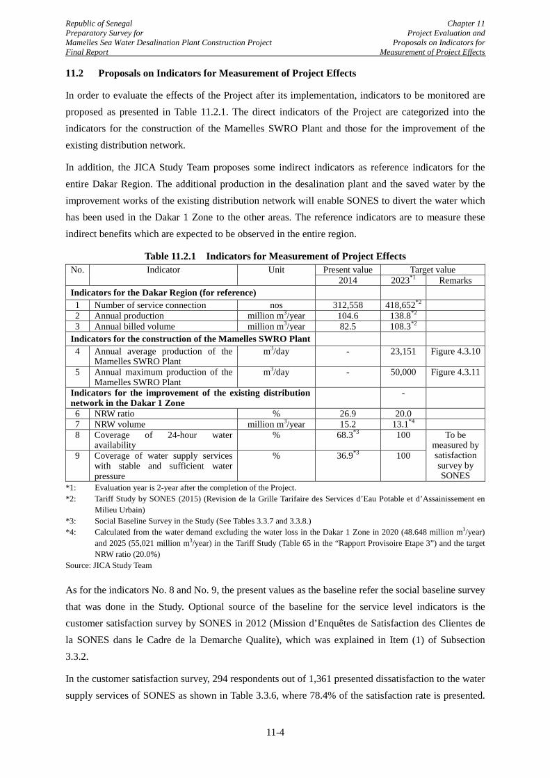
Republic of Senegal Chapter 11 Preparatory Survey for Project Evaluation and Mamelles Sea Water Desalination Plant Construction Project Proposals on Indicators for Final Report Measurement of Project Effects
11.2 Proposals on Indicators for Measurement of Project Effects
In order to evaluate the effects of the Project after its implementation, indicators to be monitored are proposed as presented in Table 11.2.1. The direct indicators of the Project are categorized into the indicators for the construction of the Mamelles SWRO Plant and those for the improvement of the existing distribution network.
In addition, the JICA Study Team proposes some indirect indicators as reference indicators for the entire Dakar Region. The additional production in the desalination plant and the saved water by the improvement works of the existing distribution network will enable SONES to divert the water which has been used in the Dakar 1 Zone to the other areas. The reference indicators are to measure these indirect benefits which are expected to be observed in the entire region.
Table 11.2.1 Indicators for Measurement of Project Effects No. Indicator Unit Present value Target value
2014 2023*1 Remarks Indicators for the Dakar Region (for reference) 1 Number of service connection nos 312,558 418,652*2 2 Annual production million m3/year 104.6 138.8*2 3 Annual billed volume million m3/year 82.5 108.3*2
Indicators for the construction of the Mamelles SWRO Plant 4 Annual average production of the
Mamelles SWRO Plant m3/day - 23,151 Figure 4.3.10
5 Annual maximum production of the Mamelles SWRO Plant
m3/day - 50,000 Figure 4.3.11
Indicators for the improvement of the existing distribution network in the Dakar 1 Zone
-
6 NRW ratio % 26.9 20.0 7 NRW volume million m3/year 15.2 13.1*4 8 Coverage of 24-hour water
availability % 68.3*3 100 To be
measured by satisfaction survey by SONES
9 Coverage of water supply services with stable and sufficient water pressure
% 36.9*3 100
*1: Evaluation year is 2-year after the completion of the Project. *2: Tariff Study by SONES (2015) (Revision de la Grille Tarifaire des Services d’Eau Potable et d’Assainissement en
Milieu Urbain) *3: Social Baseline Survey in the Study (See Tables 3.3.7 and 3.3.8.) *4: Calculated from the water demand excluding the water loss in the Dakar 1 Zone in 2020 (48.648 million m3/year)
and 2025 (55,021 million m3/year) in the Tariff Study (Table 65 in the “Rapport Provisoire Etape 3”) and the target NRW ratio (20.0%)
Source: JICA Study Team
As for the indicators No. 8 and No. 9, the present values as the baseline refer the social baseline survey that was done in the Study. Optional source of the baseline for the service level indicators is the customer satisfaction survey by SONES in 2012 (Mission d’Enquêtes de Satisfaction des Clientes de la SONES dans le Cadre de la Demarche Qualite), which was explained in Item (1) of Subsection 3.3.2.
In the customer satisfaction survey, 294 respondents out of 1,361 presented dissatisfaction to the water supply services of SONES as shown in Table 3.3.6, where 78.4% of the satisfaction rate is presented.
11-4
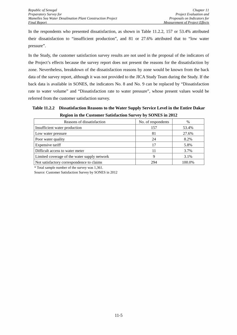
Republic of Senegal Chapter 11 Preparatory Survey for Project Evaluation and Mamelles Sea Water Desalination Plant Construction Project Proposals on Indicators for Final Report Measurement of Project Effects
In the respondents who presented dissatisfaction, as shown in Table 11.2.2, 157 or 53.4% attributed their dissatisfaction to “insufficient production”, and 81 or 27.6% attributed that to “low water pressure”.
In the Study, the customer satisfaction survey results are not used in the proposal of the indicators of the Project’s effects because the survey report does not present the reasons for the dissatisfaction by zone. Nevertheless, breakdown of the dissatisfaction reasons by zone would be known from the back data of the survey report, although it was not provided to the JICA Study Team during the Study. If the back data is available in SONES, the indicators No. 8 and No. 9 can be replaced by “Dissatisfaction rate to water volume” and “Dissatisfaction rate to water pressure”, whose present values would be referred from the customer satisfaction survey.
Table 11.2.2 Dissatisfaction Reasons to the Water Supply Service Level in the Entire Dakar Region in the Customer Satisfaction Survey by SONES in 2012
Reasons of dissatisfaction No. of respondents % Insufficient water production 157 53.4% Low water pressure 81 27.6% Poor water quality 24 8.2% Expensive tariff 17 5.8% Difficult access to water meter 11 3.7% Limited coverage of the water supply network 9 3.1% Not satisfactory correspondence to claims 294 100.0%
* Total sample number of the survey was 1,361. Source: Customer Satisfaction Survey by SONES in 2012
11-5
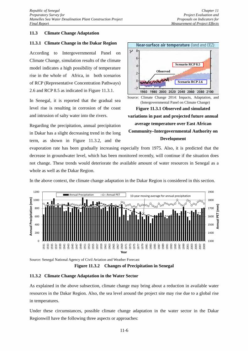
Republic of Senegal Chapter 11 Preparatory Survey for Project Evaluation and Mamelles Sea Water Desalination Plant Construction Project Proposals on Indicators for Final Report Measurement of Project Effects
1300
1400
1500
1600
1700
1800
1900
0
200
400
600
800
1000
1200
1931
1933
1935
1937
1939
1941
1943
1945
1947
1949
1951
1953
1955
1957
1959
1961
1963
1965
1967
1969
1971
1973
1975
1977
1979
1981
1983
1985
1987
1989
1991
1993
1995
1997
1999
2001
2003
2005
2007
2009
Annu
al P
ET (m
m)
Annu
al P
reci
pita
tion
(mm
)
Year
Annual Precipitation Annual PET 10-year moving average for annual precipitation
Source: Climate Change 2014: Impacts, Adaptation, and
(Intergovernmental Panel on Climate Change)
Figure 11.3.1 Observed and simulated variations in past and projected future annual
average temperature over East African Community–Intergovernmental Authority on
Development
11.3 Climate Change Adaptation
11.3.1 Climate Change in the Dakar Region
According to Intergovernmental Panel on Climate Change, simulation results of the climate model indicates a high possibility of temperature rise in the whole of Africa, in both scenarios of RCP (Representative Concentration Pathways) 2.6 and RCP 8.5 as indicated in Figure 11.3.1.
In Senegal, it is reported that the gradual sea level rise is resulting in corrosion of the coast and intrusion of salty water into the rivers.
Regarding the precipitation, annual precipitation in Dakar has a slight decreasing trend in the long term, as shown in Figure 11.3.2, and the evaporation rate has been gradually increasing especially from 1975. Also, it is predicted that the decrease in groundwater level, which has been monitored recently, will continue if the situation does not change. These trends would deteriorate the available amount of water resources in Senegal as a whole as well as the Dakar Region.
In the above context, the climate change adaptation in the Dakar Region is considered in this section.
Source: Senegal National Agency of Civil Aviation and Weather Forecast
Figure 11.3.2 Changes of Precipitation in Senegal
11.3.2 Climate Change Adaptation in the Water Sector
As explained in the above subsection, climate change may bring about a reduction in available water resources in the Dakar Region. Also, the sea level around the project site may rise due to a global rise in temperatures.
Under these circumstances, possible climate change adaptation in the water sector in the Dakar Regionwill have the following three aspects or approaches:
Scenario RCP 2.6
Scenario RCP 8.5
Observed
11-6
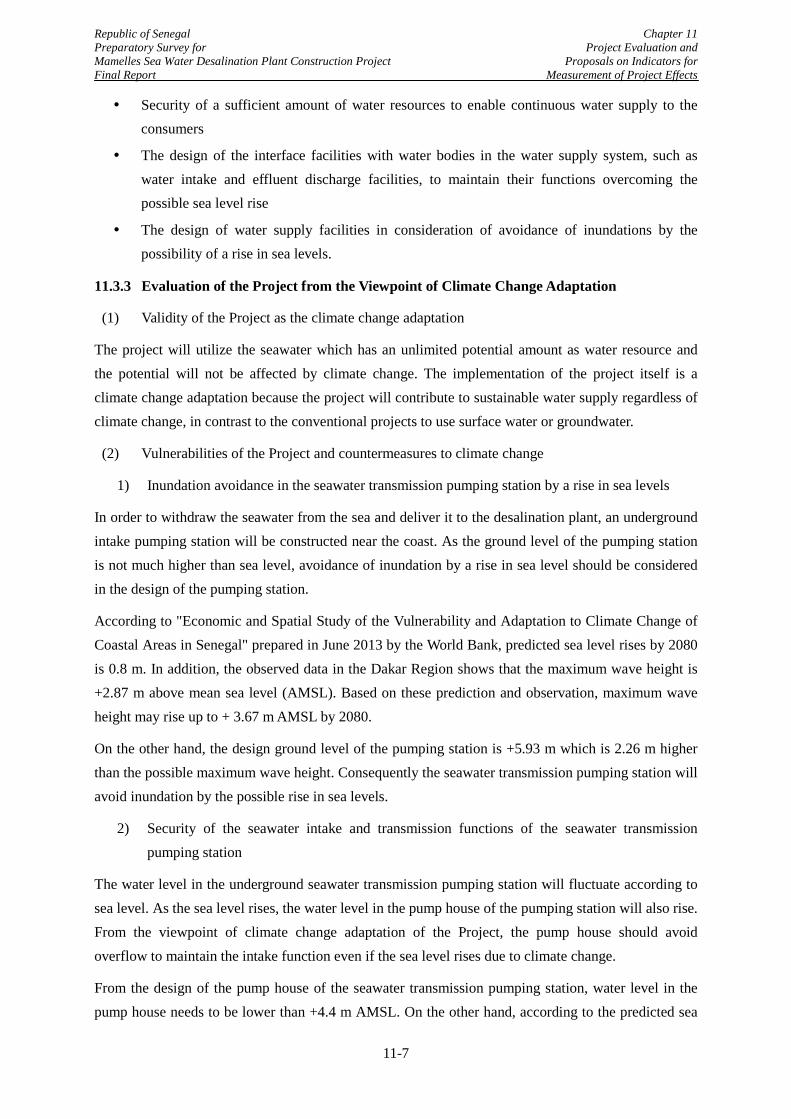
Republic of Senegal Chapter 11 Preparatory Survey for Project Evaluation and Mamelles Sea Water Desalination Plant Construction Project Proposals on Indicators for Final Report Measurement of Project Effects
Security of a sufficient amount of water resources to enable continuous water supply to the consumers
The design of the interface facilities with water bodies in the water supply system, such as water intake and effluent discharge facilities, to maintain their functions overcoming the possible sea level rise
The design of water supply facilities in consideration of avoidance of inundations by the possibility of a rise in sea levels.
11.3.3 Evaluation of the Project from the Viewpoint of Climate Change Adaptation
(1) Validity of the Project as the climate change adaptation
The project will utilize the seawater which has an unlimited potential amount as water resource and the potential will not be affected by climate change. The implementation of the project itself is a climate change adaptation because the project will contribute to sustainable water supply regardless of climate change, in contrast to the conventional projects to use surface water or groundwater.
(2) Vulnerabilities of the Project and countermeasures to climate change
1) Inundation avoidance in the seawater transmission pumping station by a rise in sea levels
In order to withdraw the seawater from the sea and deliver it to the desalination plant, an underground intake pumping station will be constructed near the coast. As the ground level of the pumping station is not much higher than sea level, avoidance of inundation by a rise in sea level should be considered in the design of the pumping station.
According to "Economic and Spatial Study of the Vulnerability and Adaptation to Climate Change of Coastal Areas in Senegal" prepared in June 2013 by the World Bank, predicted sea level rises by 2080 is 0.8 m. In addition, the observed data in the Dakar Region shows that the maximum wave height is +2.87 m above mean sea level (AMSL). Based on these prediction and observation, maximum wave height may rise up to + 3.67 m AMSL by 2080.
On the other hand, the design ground level of the pumping station is +5.93 m which is 2.26 m higher than the possible maximum wave height. Consequently the seawater transmission pumping station will avoid inundation by the possible rise in sea levels.
2) Security of the seawater intake and transmission functions of the seawater transmission pumping station
The water level in the underground seawater transmission pumping station will fluctuate according to sea level. As the sea level rises, the water level in the pump house of the pumping station will also rise. From the viewpoint of climate change adaptation of the Project, the pump house should avoid overflow to maintain the intake function even if the sea level rises due to climate change.
From the design of the pump house of the seawater transmission pumping station, water level in the pump house needs to be lower than +4.4 m AMSL. On the other hand, according to the predicted sea
11-7
Republic of Senegal Chapter 11 Preparatory Survey for Project Evaluation and Mamelles Sea Water Desalination Plant Construction Project Proposals on Indicators for Final Report Measurement of Project Effects
level rise by 0.8 m by 2080, observed maximum tidal level over five years (+1.04 m) and the head loss in the marine seawater intake pipe (1.64 m).Consequently the possible maximum water level in the pump house is + 0.2 m(+1.04 m + 0.8 m – 1.64 m) AMSL, which is lower than the acceptable water level in the pump house of +4.4 m.
Therefore, the water intake function of the seawater transmission pumping station will be maintained regardless of any rise in sea level.
3) Maintenance of discharge rate of brine to the sea
Brine from the desalination plant is designed to be discharged into the sea by gravity flow utilizing the difference of water levels between the effluent tank in the desalination plant and sea level. Therefore, a rise in sea level may deteriorate the capacity of the brine discharge pipeline.
However, the present difference in the water levels between the effluent tank and the sea is more than 40 m. The possible rise in sea level, which is predicted as 0.8 m by 2080, will not have an impact in decreasing the capacity of the brine discharge pipe.
11-8
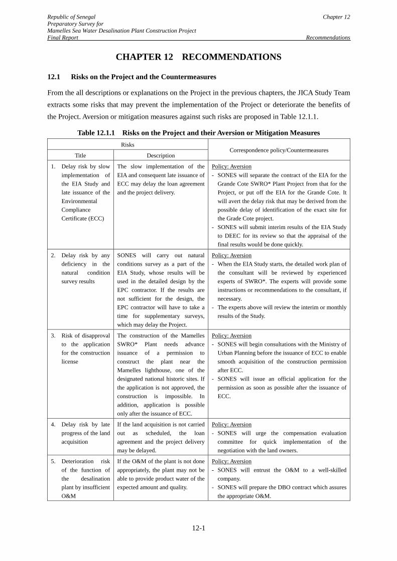
Republic of Senegal Chapter 12 Preparatory Survey for Mamelles Sea Water Desalination Plant Construction Project Final Report Recommendations
CHAPTER 12 RECOMMENDATIONS
12.1 Risks on the Project and the Countermeasures
From the all descriptions or explanations on the Project in the previous chapters, the JICA Study Team extracts some risks that may prevent the implementation of the Project or deteriorate the benefits of the Project. Aversion or mitigation measures against such risks are proposed in Table 12.1.1.
Table 12.1.1 Risks on the Project and their Aversion or Mitigation Measures Risks
Correspondence policy/Countermeasures Title Description
1. Delay risk by slow implementation of the EIA Study and late issuance of the Environmental Compliance Certificate (ECC)
The slow implementation of the EIA and consequent late issuance of ECC may delay the loan agreement and the project delivery.
Policy: Aversion - SONES will separate the contract of the EIA for the
Grande Cote SWRO* Plant Project from that for the Project, or put off the EIA for the Grande Cote. It will avert the delay risk that may be derived from the possible delay of identification of the exact site for the Grade Cote project.
- SONES will submit interim results of the EIA Study to DEEC for its review so that the appraisal of the final results would be done quickly.
2. Delay risk by any deficiency in the natural condition survey results
SONES will carry out natural conditions survey as a part of the EIA Study, whose results will be used in the detailed design by the EPC contractor. If the results are not sufficient for the design, the EPC contractor will have to take a time for supplementary surveys, which may delay the Project.
Policy: Aversion - When the EIA Study starts, the detailed work plan of
the consultant will be reviewed by experienced experts of SWRO*. The experts will provide some instructions or recommendations to the consultant, if necessary.
- The experts above will review the interim or monthly results of the Study.
3. Risk of disapproval to the application for the construction license
The construction of the Mamelles SWRO* Plant needs advance issuance of a permission to construct the plant near the Mamelles lighthouse, one of the designated national historic sites. If the application is not approved, the construction is impossible. In addition, application is possible only after the issuance of ECC.
Policy: Aversion - SONES will begin consultations with the Ministry of
Urban Planning before the issuance of ECC to enable smooth acquisition of the construction permission after ECC.
- SONES will issue an official application for the permission as soon as possible after the issuance of ECC.
4. Delay risk by late progress of the land acquisition
If the land acquisition is not carried out as scheduled, the loan agreement and the project delivery may be delayed.
Policy: Aversion - SONES will urge the compensation evaluation
committee for quick implementation of the negotiation with the land owners.
5. Deterioration risk of the function of the desalination plant by insufficient O&M
If the O&M of the plant is not done appropriately, the plant may not be able to provide product water of the expected amount and quality.
Policy: Aversion - SONES will entrust the O&M to a well-skilled
company. - SONES will prepare the DBO contract which assures
the appropriate O&M.
12-1
Republic of Senegal Chapter 12 Preparatory Survey for Mamelles Sea Water Desalination Plant Construction Project Final Report Recommendations
Risks Correspondence policy/Countermeasures
Title Description
6. Risk of deteriorated benefit of the Project by low operation rate of the plant
The operation rate of the plant may be low because of its high operation cost. Too low operation rate may result in deterioration of the expected benefit of the Project.
Policy: Mitigation - SONES will introduce a mechanism to determine the
best balance in the water productions from the available water sources in viewpoint of the water resource diversity.
- SONES will prepare the O&M contract of the plant so that the operation cost will be appropriately compensated to the O&M executor.
7. Risk of deteriorated benefit of the Project by deficiencies in the distribution system
Possible failures in the water distribution system from the Mamelles Reservoir may prevent the production from the Mamelles SWRO Plant from being delivered to the water users.
Policy: Mitigation - Aged deterioration should be accepted to some
degree. However, SONES will supervise the Affermage contractor so that inspections and maintenance of the facilities will be done carefully, especially for the important facilities with not backup.
*SWRO: Seawater desalination by reverse osmosis Source: JICA Study Team
12.2 Recommendations on Possible Cooperation among the Donors for Improvement of the Water Supply Services in the Dakar Region
As described in Section 10.4, SONES has done a study on the future water rate level for sustainable water supply services and the study has concluded that the water rate needs to be raised by 37% at maximum by 2025 to cover the costs for the planned large-scaled projects to be implemented soon and the O&M cost of the SWRO plants. On the other hand, willingness to pay (WTP) of the water users to the water supply services are only at the same level of the present water rate, which was confirmed in the social baseline survey in the Study, too.
In order to maintain the status as the well-received water supply provider to the users, SONES needs to make efforts to expand understanding and cooperation to the water supply services among the citizens. The JICA Study Team recommends that the donors will jointly assist SONES in such efforts which will include the following activities:
Publicity of the achieved improvement in the water supply services and the visions and plans of the further improvement
Awareness program for the necessity of appropriate share among the users of the service cost by water tariff, for sustainability of the water supply services
In the technical viewpoint, the donors have plans to provide financial assistances to the constructions of the additional water production facilities such as wells, water treatment plants and seawater desalination plants. As pointed out in the Study, however, there are much potential of water saving by water loss reduction in the Dakar Region. The water loss recovery will reduce the investment on the additional water production facilities, which will accordingly mitigate the hike in the water rate.
12-2
Republic of Senegal Chapter 12 Preparatory Survey for Mamelles Sea Water Desalination Plant Construction Project Final Report Recommendations
In order for SONES to achieve the water reduction, it is necessary that SONES and the donors will share the present conditions of the water loss in the region and an integrated plan for the reduction. The JICA Study Team recommends that the donors will also jointly assist SONES in the water loss reduction which will need the following activities:
Improvement of the existing inventory database and the distribution network map which are the fundamental information for establishment and implementation of the valid water loss reduction plan.
Investigation and study on the present conditions and causes of the water loss in the Dakar Region.
Determination of the target level of the water loss reduction, which will achieve the best financial balance between the investments on the water loss reduction and the new water production facilities
Establishment of the middle and long term plans of water loss reduction and securement of the budget for its implementation.
In the Project, water losses in Dakar 1 Zone, where the water loss conditions are the worst in the Dakar Region, will be reduced but the good conditions achieved by the Project should be maintained. In addition, the conditions in Dakar 2 Zone and Rufisque Zone may be deteriorated gradually in the near future. Therefore, it is expected that the donors would provide assistances to SONES so that it could carry out appropriate monitoring and maintenance of the water distribution network for the entire Dakar Region.
12-3