
REPRINTED FROM November 2016 … · Choosing the Right Communication Protocol ... Factors affecting...
8
www.chemengonline.com November 2016 Choosing the Right Communication Protocol ELECTRONICALLY REPRINTED FROM
Transcript of REPRINTED FROM November 2016 … · Choosing the Right Communication Protocol ... Factors affecting...

www.chemengonline.com
November2016
Choosing the Right Communication Protocol
ELECTRONICALLYREPRINTED FROM

When using throttling valves in closed-loop process control, a variety of factors impact the selection of the most appropri-
ate communications network. Chief among them are performance and installation cost.
Within the chemical process industries (CPI), three networking technologies are commonly used to interface throttling valves with the automation system: 4–20 mA with HART, fieldbus and wireless. This article ex-amines these three options, and also pro-vides information on emerging technologies to improve control performance.
Factors affecting control performancePerformance in a closed-loop control appli-cation depends on the dynamic response of the controller, valve, measurement and pro-cess (Figure 1). To achieve a target control objective, it is necessary to consider all of
these components (see sidebar, Value and Positioner Technology).
Performance and cost discussions should always start with the process, but care should be taken not to focus on one area and exclude others. For example, the valve should be considered along with the rest of the process-loop elements to achieve oper-ating objectives. There are three main criteria that may be used to evaluate closed-loop throttling-valve control: process variability, reliability and control responsiveness.
Reduced process variability can provide a competitive advantage in manufacturing and can lead to higher operating profits. As an example, some processes have a maximum allowable operating pressure (MAOP, Figure 2), and the closer to the MAOP that the pro-
Terry Blevins and Kurtis JensenEmerson
Closed-loop control performance depends on the dynamic response of the controller, valve, measurement and process. Can wireless compete with conventional networks?
Communication Technologies for Throttling Valve Control
FIGURE 1. Several factors can affect the performance of the control loop for a throttling valve
IN BRIEFFACTORS AFFECTING
CONTROL PERFORMANCE
4–20 mA WITH HART
FOUNDATION FIELDBUS AND PROFIBUS PA
WIRELESSHART
COMPARING INTERFACE TECHNOLOGIES
FUTURE ENHANCEMENTS
• Set point - change frequency• Control macrocycle
n Sampling intervaln PID executionn Output interval
• Resolutionn Accuracy
• Dead timen Actuation capacity
• Stoking speedn Mechanical velocity
• Resolutionn Sensitivity
• Dead timen Filtering and dampening
• Sampling interval
• Dead time (delay)• Time constant (lag)• Gain (sensitivity)• Process disturbance
Controller
Measurement
Valve
Process
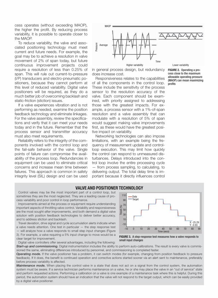
cess operates (without exceeding MAOP), the higher the profit. By reducing process variability, it is possible to operate closer to the MAOP.
To reduce variability, the valve and asso-ciated positioning technology must meet current and future needs. For example, the goal may be to achieve a resolution in valve movement of 2% of span today, but future continuous improvement projects could require a resolution of less than 0.25% of span. This will rule out current-to-pressure (I/P) transducers and electro-pneumatic po-sitioners, because they cannot perform at this level of reduced variability. Digital valve positioners will be required, as they do a much better job of overcoming backlash and static-friction (stiction) issues.
If a valve experiences vibration and is not performing as needed, examine the position feedback technology and eliminate linkages. For the valve assembly, review the specifica-tions and verify that it can meet your needs today and in the future. Remember that the process sensor and transmitter accuracy must also meet requirements.
Reliability refers to the integrity of the com-ponents involved with the control loop and the fail-safe behavior of the valve. Single points of failure can compromise the avail-ability of the process loop. Redundancies in equipment can be used to eliminate critical concerns and increase mean time between failures. This approach is common in safety integrity level (SIL) design and can be used
in general process design, but redundancy does increase cost.
Responsiveness relates to the capabilities of all the components in the control loop. These include the sensitivity of the process sensor to the resolution accuracy of the valve. Each component should be exam-ined, with priority assigned to addressing those with the greatest impacts. For ex-ample, a process sensor with a 1%-of-span resolution and a valve assembly that can modulate with a resolution of 5% of span would suggest making valve improvements first, as these would have the greatest posi-tive impact on variability.
Networking technologies can also impose limitations, with an example being the fre-quency of measurement update and control-loop execution. This may limit how quickly the control can respond to unmeasured dis-turbances. Delays introduced into the con-trol loop involve the entire processing cycle — from process sampling, to calculating, to delivering output. The total delay time is im-portant because it directly influences control
FIGURE 2. Operating a pro-cess close to the maximum allowable operating pressure (MAOP) can mean maximizing profits
VALVE AND POSITIONER TECHNOLOGYControl valves may be the most important part of a control loop, but
sometimes they are the most neglected. They are a leading cause of pro-cess variability and poor control in loop performance.
Improvements aimed at the process or equipment require understanding important aspects of throttling valve control. Variability and responsiveness are the most sought-after improvements, and both demand a digital valve solution with position feedback technologies to deliver better accuracy, and to address stiction and backlash.
Travel deviation, drive signal and cycle accumulation alerts indicate when a valve needs attention. One test in particular — the step response test — will analyze how a valve responds to small step input changes (Figure 3). For example, a valve requiring a 5% input change to move would be a clear target for improvement.
Digital valve controllers offer several advantages, including the following:Start-up and commissioning. Digital instrumentation includes the ability to perform auto-calibrations. The result is every valve is commis-sioned the same, eliminating differences introduced by personnel, and commissioning is completed faster. Operating mode. If the valve positioner has a problem, it can switch modes (for example, changing from position feedback to pressure feedback). If it does, the benefit is continued operation and corrective actions started sooner via an alert sent to maintenance, preferably before process variability is affected.Maintenance mode. When placing the control valve in a state that does not act on a signal from the control system, the automation system must be aware. If a service technician performs maintenance on a valve, he or she may place the valve in an “out of service” state and perform requested actions. Performing a calibration on a valve is one example of a maintenance task where this is helpful. During this period, the automation system should have an indication that the valve will not respond to the target output, which can be easily provided by a digital valve positioner.
FIGURE 3. A step-response test measures how a valve responds to small input changes
Time
MAOP
Average
Higher variability Lower variability
Pres
sure
X: -25.29Y: -0.93
Trav
el (%
)
110
90
70
50
30
10
-10
-10 0 10 20 30 40 50 60 70 80 90Time (secs)
DataTarget

performance and may affect controller tuning.The three main networking technologies
used in the CPI for interfacing the automa-tion system to field devices are:• 4–20 mA with HART • Fieldbus (Foundation Fieldbus or Profibus
PA)• WirelessHART
An examination of each shows both ad-vantages and concerns.
4–20 mA with HARTPlants constructed in the 20th century are, in most cases, instrumented with field devices in-terfacing to the automation system using 4–20-mA current signals for both measurement and control. These field devices typically have digital electronics and support HART communica-tions superimposed upon the 4–20-mA signal.
HART communications is relatively slow (1,200 baud — units for pulses per second), so the 4–20-mA interface is typically used for process measurements sent to the automation system by field devices, and for control signals sent to throttling valves by the automation sys-tem. HART communications is typically used for diagnostics and calibration.
To avoid disruption of HART communica-tions, the rate of change in the current signal is normally limited by the transmitter and digi-tal valve positioner. For example, the transition time for a change from 4 mA to 20 mA may require 120 milliseconds (ms). From a practi-cal standpoint, this limitation on rate of change
has little or no impact on closed-loop control.
The rate at which the transmitter updates the 4–20-mA signal to reflect changing process condi-tions, the rate at which the automation system ac-cesses the transmitter’s 4–20-mA signal, and any delay introduced in pro-cessing the 4–20-mA con-trol signal to a valve can directly impact the closed-loop control of fast pro-cesses, such as liquid flow or pressure. These delays add up and can directly impact PID (proportional-integral-derivative) control performance.
For example, when trans-mitter, controller I/O (input/output) scan rate, position update rate and automation
system controller-output process time are each 50 ms, then a maximum delay of 200 ms and average delay of 100 ms may be introduced. Some transmitters, controllers and valves pro-vide even slower update rates, and the result-ing delay can degrade the control of fast pro-cesses. The transmitter, controller and valve positioner should be carefully selected based on their update rate when addressing control of fast processes.
With 4–20-mA control configurations, there are several single points of failure: from the con-troller to the I/O; the I/O itself; and the wiring from the I/O to the sensor or controller (Figure 4). Any single failure will affect the operation of a closed-loop process control structure.
When installing wiring for 4–20 mA with HART, a cable consisting of a single twisted pair of shielded wires is required for each mea-surement or valve. Dedicated wiring to each field device limits the impact of a short-circuit or opening in the wiring to one device. The costs of the cable, labor to install the cable and checking out each wiring connection between a field device and the automation system are significant.
In some cases, the cable cost and installation labor may be reduced by using multi-conductor cable between the automation system control-ler and a junction box in the field. These savings are often offset by the increased time required to document and check out the additional junc-tion box connections. Alternatively, some con-trollers are designed to allow I/O cards to be remotely mounted, but the cost of providing a housing to adequately protect the I/O cards while allowing maintenance access may far ex-ceed any savings in cable cost.
Cost and performance considerations for 4–20 mA with HART include the following:• The technology is very mature and its
operation is deterministic, providing solid performance. The overall loop execution period depends mainly on the automation system vendor and can range from 20 ms to several seconds
• HART communication can be used for diagnostics and calibration, but the 4–20-mA current signal should be used in control applications
• Loop integrity can be considered low with a single pressure sensor, single analog input, single PID controller, single analog output and single valve positioner. Adding redundancy is difficult and expensive
• Diagnostics and alerts provided by HART-enabled devices can help plant operators detect problems quickly, sometimes before they occur, and help transition from reac-
FIGURE 4. A 4–20 mA with HART connection requires a two-wire twisted pair from the I/O to the transmitter and valve, and a connection from the I/O to the controller. Potential points of failure are enclosed by the red boxes
FIGURE 5. Fieldbus is a digital communication system al-lowing multiple devices to connect on a segment. Re-dundancy options decrease failure points and improve integrity
Emerson
Emerson

tive to proactive maintenance
Foundation Fieldbus and Profibus PASoon after 4–20 mA was approved as an international standard, work started on a fieldbus standard to support total digital communication with field devices. The In-ternational Electrotechnical Commission (IEC; Geneva, Switzerland; www.iec.ch) international fieldbus standard IEC61158 defines a physical layer for digital commu-nications over existing twisted pair wiring installed in a plant. Various fieldbus com-munication protocols are defined in this standard.
The reasons for the wide acceptance of fieldbus in new plant construction include the following:• A single twisted pair of wires may be
used between a controller and junction box and then fanned out to multiple field devices (Figure 5). The wiring savings are significant compared to a 4–20-mA installation
• All field devices on a segment commu-nicate and receive power over a single twisted pair connection to the controller, eliminating the need to supply power to each device separately
• As devices join the segment, the factory tag for the device is available to com-mission the device. Wiring checkout is faster, with wiring mistakes minimized
• All the measurement values available in a device — such as pressure, mass flow, temperature and other parameters in a Coriolis flowmeter — may be ac-cessed through the digital communica-tions link
• Valve-stem position feedback is avail-able from a digital valve positioner
• The maximum distance between the controller and field device is compa-rable to 4–20-mA installations.Fieldbus supports quick access to op-
erational and diagnostic information in a field device. Also, the entire control loop may be moved to the field devices with Foundation Fieldbus to implement control in the field. Function blocks used for con-trol are automatically scheduled, resulting in deterministic and synchronized control execution.
The macrocycle is the time it takes to process the input, perform the PID calcu-lation, and then develop the output. There are differences in products affecting both the macrocycle and loop execution period.
For example, in a typical control loop
where measurement and control are done in the fieldbus transmitter, there is only a 55 ms delay between measurement availabil-ity and control action initiated in the valve (Figure 6).
Thus, by using control in the field, it is possible to achieve control performance comparable to 4–20-mA devices and net-works. When control is performed at the automation system instead of in the field (Figure 8), an added delay is introduced in the control loop since the measurement, control and output to the valve are not syn-chronized.
When addressing faster applications, this additional delay can degrade control performance. Also, as more devices are added to a fieldbus segment, the macro-cycle may be extended, which can affect how quickly the control can respond to a process disturbance.
The added cost of a fieldbus device ver-sus an equivalent 4–20-mA device is offset by the significant wiring savings, and by the reduction in the time to engineer, install and check out a fieldbus installation. Also, expanded diagnostics available with field-bus devices can reduce the time required to resolve an operational problem.
But in a fieldbus installation, differ-ent tools and knowledge are required to achieve benefits. Thus, in a new installa-tion, personnel involved in installation and checkout must be trained on the proper methods required to install and commis-sion fieldbus devices. Changes will be re-quired in the tools used to engineer and document the automation system wiring and installation.
Cost and performance considerations for Foundation Fieldbus and Profiibus in-clude the following:• Fieldbus technology and its operation
is deterministic, providing solid perfor-mance
• The overall loop execution period can range from less than 100 ms with con-trol in the field, to several seconds with
FIGURE 6. When a fieldbus device per-forms sampling and control in the field, the macrocycle (time to perform the entire operation) is very fast (about 55 ms)
Time
Macrocycle
Processsampling
PIDexecution
Output to valve

control by the automation system for more complex designs having multiple devices per segment. Thus, the number of devices on a segment should be limited when ad-dressing control of fast-reacting processes
• Loop integrity can be considered low with a single pressure sensor, a single analog input, a single PID controller, a single analog out-put and a single digital valve positioner. Re-dundancies at the control system interface and elsewhere can be added to increase loop integrity
• Diagnostics and alerts are included in devices to enable proactive maintenance practices, but the amount of information sent on the fieldbus link will increase macro-cycle times
• The installation and total installed costs can be 30–40% less than with 4–20-mA wired technology. This includes savings on engi-neering, cabling and system devices
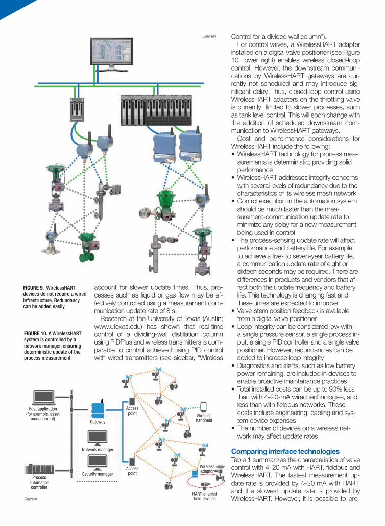
WirelessHARTIn an existing plant, installation of a new trans-mitter or valve may be quite costly when new wiring must be installed, and installation time may be excessive. WirelessHART devices (Fig-ure 9) address these issues.
In new plant construction, many manufac-turers find that installation and commissioning costs can be reduced by using WirelessHART field devices. When installing field devices in re-mote locations, such as in waste- and water-treatment areas, significant savings may be realized by eliminating wiring. The market for WirelessHART has grown significantly, leading to interest in using wireless for closed loop con-trol.
WirelessHART field-device transmission can be slow. In particular, battery-powered trans-mitters may be configured to transmit only pe-riodically — such as every 8 s — to achieve a battery life of five to seven years. For this rea-son, many engineers have been using wireless more for monitoring, and consider wireless too slow for control purposes.
But WirelessHART devices powered locally do not have the disadvantage of a slow update time. Update rates can be much faster, be-cause there is no battery life concern. Energy harvesting devices that convert temperature or vibration to power can also allow WirelessHART devices to transmit at a faster rate.
In a WirelessHART network, all communi-cations are scheduled by the WirelessHART network manager (Figure 10). The result is the deterministic update of a measurement used in process control. In other words, whatever mea-surement update time is required, the network manager will schedule it, within the limits of the technology.
To address control of processes with a re-sponse time of 30 s or less — such as liquid or gas flow — a modified version of the PID algorithm called PIDPlus can be used. PIDP-lus modifies the PID algorithm to automatically
WIRELESS CONTROL FOR A DIVIDED WALL COLUMNFor the past six years, the University of Texas at Austin’s Separation Research Program has been study-
ing the use of wireless technologies in a dividing wall column (DWC) distillation process. At the University of Texas installation (Figure 7), column temperature, tray level and flow measurements are made using WirelessHART transmitters.
Closed-loop control using wireless temperature measurements, steam flow, liquid flow is accomplished using PIDPlus. Heater temperature control is based on PIDPlus, and temperature measurement is pro-vided by a WirelessHART transmitter.
PIDPlus provides effective control using the typical wireless update rates of eight to sixteen seconds, which are required to achieve a five- to seven-year battery life. It is possible to control using wireless measurements while delivering performance comparable to traditional wired transmitters and wired final control elements in certain applications. The modifications in PID introduced by PIDPlus are designed to handle loss of communication, and to enable control using relatively slow measurement and non-periodic measurement updates.
The control design implemented on the DWC at the University of Texas has proven to be effective in providing stable column operation. Experience with the column operation over a variety of operating con-ditions has shown the following:• Closed loop control using wireless measurements and PIDPlus effectively addresses relatively fast pro-
cesses, such as liquid flow and steam flow, as well as slower processes, such as temperature control, using an eight-second periodic communication update rate
• Model predictive control satisfies process control requirements using wireless instrumentation. For the DWC control, model predictive control has been shown to outperform single loop control
FIGURE 8. When control is accomplished in the control system, additional delay is introduced because control actions are not synchronized with fieldbus processing
FIGURE 7. The divided wall column at the University of Texas at Austin’s Pilot Plant is controlled using Wire-lessHART networking technology
Emerson
Emerson
account for slower update times. Thus, pro-cesses such as liquid or gas flow may be ef-fectively controlled using a measurement com-munication update rate of 8 s.
Research at the University of Texas (Austin; www.utexas.edu) has shown that real-time control of a dividing-wall distillation column using PIDPlus and wireless transmitters is com-parable to control achieved using PID control with wired transmitters (see sidebar, “Wireless
Control for a divided wall column”).For control valves, a WirelessHART adapter
installed on a digital valve positioner (see Figure 10, lower right) enables wireless closed-loop control. However, the downstream communi-cations by WirelessHART gateways are cur-rently not scheduled and may introduce sig-nificant delay. Thus, closed-loop control using WirelessHART adapters on the throttling valve is currently limited to slower processes, such as tank level control. This will soon change with the addition of scheduled downstream com-munication to WirelessHART gateways.
Cost and performance considerations for WirelessHART include the following:• WirelessHART technology for process mea-
surements is deterministic, providing solid performance
• WirelessHART addresses integrity concerns with several levels of redundancy due to the characteristics of its wireless mesh network
• Control execution in the automation system should be much faster than the mea-surement-communication update rate to minimize any delay for a new measurement being used in control
• The process-sensing update rate will affect performance and battery life. For example, to achieve a five- to seven-year battery life, a communication update rate of eight or sixteen seconds may be required. There are differences in products and vendors that af-fect both the update frequency and battery life. This technology is changing fast and these times are expected to improve
• Valve-stem position feedback is available from a digital valve positioner
• Loop integrity can be considered low with a single pressure sensor, a single process in-put, a single PID controller and a single valve positioner. However, redundancies can be added to increase loop integrity
• Diagnostics and alerts, such as low battery power remaining, are included in devices to enable proactive maintenance practices
• Total installed costs can be up to 90% less than with 4–20-mA wired technologies, and less than with fieldbus networks. These costs include engineering, cabling and sys-tem device expenses
• The number of devices on a wireless net-work may affect update rates
Comparing interface technologiesTable 1 summarizes the characteristics of valve control with 4–20 mA with HART, fieldbus and WirelessHART. The fastest measurement up-date rate is provided by 4–20 mA with HART, and the slowest update rate is provided by WirelessHART. However, it is possible to pro-
FIGURE 9. WirelessHART devices do not require a wired infrastructure. Redundancy can be added easily
FIGURE 10. A WirelessHART system is controlled by a network manager, ensuring deterministic update of the process measurement
HART-enabled field devices
Host application(for example, asset
management)
Process automation controller
Gateway
Network manager
Security manager
Accesspoint
Accesspoint
Wireless handheld
Wireless adaptor
Emerson
Emerson

vide comparable control performance using a modified PID algorithm.
The most expensive solution is 4–20 mA with HART because of the extensive wiring in-frastructure needed, and the least expensive is WirelessHART because it does not need a wired infrastructure.
While the table shows the typical communica-tion update rates is 8 s to provide a 5–7-year battery life, this update rate can be set much faster when powered wireless field devices are used.
Future enhancements Quickly evolving and advancing areas are wireless for control and an all-digital control structure. Improvements and prog-ress have been made recently, including advances in control algorithms such as PIDPlus. Intelligence in field instruments is now being leveraged so controllers act only when needed, which enables effective control using slower update rates.
Another area of progress is pushing more intelligence to field devices. Fieldbus-based technologies include control in the field already, but much more can be done in this area by increasing use of this capability.
HART-IP (internet protocol) will be an interesting technol-ogy as it evolves and enables greater speed and bandwidth. The underlying physical structure is independent and can be applied to multiple communication technologies such as Wi-Fi, Bluetooth and fiber-based structures.
Digital communications can eliminate the need for field de-vices and control system I/O to perform many A/D (analog to digital) and D/A (digital to analog) conversions. Increased use of digital communications will reduce the need for 4–20-mA field instruments.
With the increase in intelligence, new modes of operation will evolve. Digital intelligence will bring with it the ability to use “triggers.” These triggers and how long they exist will be used to make value-added decisions. For example: if the target set point from the automation system has not been seen by a field-based device for an extended period of time (meaning a potential loss of communications), the valve can be smart enough to move to a pre-determined set-ting. Likewise, if and when the failure trigger goes away, the valve can follow pre-determined scenarios before returning to normal operation. The result will increase the integrity of process control.
When you consider a new digital-only environment, there are many opportunities for improvement that will translate into higher equipment reliability, reduced process variability and cost reductions.
Concluding remarksThrottling valve control has relied on 4–20 mA with HART and fieldbus interfaces for decades. Wireless adapters are available today for use with digital valve positioner, and wireless field devices are also available. However, the delay introduced by wireless downstream communications lim-its the use of wireless valve positioner to control of slower processes. As scheduled downstream communication sup-port is added to WirelessHART gateways, wireless throttling valves will increasingly be used in the control of faster pro-cesses. n Edited by Scott JenkinsAuthors
Terry Blevins (ret.) led the development of DeltaV advanced con-trol products at Emerson Process Management (19200 North-west Freeway, Houston, TX 77065; Phone: 281-477-4100). Blevins co-authored the book “Wireless Control Foundation,” and the ISA bestselling books “Advanced Control Foundation” and “Control Loop Foundation.” Blevins received a M.S.E.E. Science in Electrical Engineering degree from Purdue University. He is a member of Control magazine’s Process Automation Hall of Fame and an ISA Fellow. Terry was a principal technologist in the ap-plied research team at Emerson Process Management.
Kurtis Jensen is a marketing manager for Emerson (same ad-dress as above; Phone: 281-477-4100; Email: [email protected]), responsible for new product development, and where he serves as an advocate and promoter of innovative tech-nology that benefits end users. He has over 35 years of experience in field service, control systems, SCADA, remote terminal units (RTUs), communications, wireless technologies and field instru-mentation.
TABLE 1. COMPARING INTERFACE TECHNOLOGIES
Interface technology comparison
4–20 mA with HART
Fieldbus Wireless
Measurement update rate 50 ms 100 ms to several seconds depending on the number of devices on a segment
8–16 s typical
Total installed cost Base 30–40% lower Up to 90% lower
Communications integrity Low High High
Posted with permission from November 2016. Chemical Engineering, Access Intelligence, Copyright 2016. All rights reserved.For more information on the use of this content, contact Wright’s Media at 877-652-5295
126389