
Report Writing Group 7. Chapter 1 & 2
17
Report Writing Member: Aqmal Hidayat Adio J Abhen Erit Fernando Rahmadian Pratama Rice Putra Effendi Teguh Maulana Hardi Univesitas Andalas 2013
-
Upload
teguh-hardi -
Category
Documents
-
view
222 -
download
0
Transcript of Report Writing Group 7. Chapter 1 & 2

7/27/2019 Report Writing Group 7. Chapter 1 & 2
http://slidepdf.com/reader/full/report-writing-group-7-chapter-1-2 1/17
Report Writing
Member:
Aqmal Hidayat
Adio J Abhen
Erit Fernando
Rahmadian Pratama
Rice Putra Effendi
Teguh Maulana Hardi
Univesitas Andalas
2013

7/27/2019 Report Writing Group 7. Chapter 1 & 2
http://slidepdf.com/reader/full/report-writing-group-7-chapter-1-2 2/17
CHAPTER I
Introduction
1.1 Background
In past, the production system is done manually or by using human power. We know
that, people have different strengths, and it led to less effective in an industrial production
process. The effectiveness of the production can be seen from how many products are
produced in a short time.
Now, then comes a new branch of science that mechatronics is a synergisticcombination of mechanics, electronics and information systems science that can not be
separated from one another.
At the present time, Mechatronics very useful in the industrial world because it can
help the process of the production process a raw material into a product in a short time and
can also directly save on production costs..
Mechatronic applications at this time have been found and functions facilitate human
work. However still rarely applied in people's lives. This is due to the lack of public
knowledge about the working principles of mechatronics applications and people are still
accustomed to using the old technology. So in this report the author discusses in more depth
about mekatonika applications so that people can know the many benefits of technological
advances such as mechatronic applications.
1.2 Purpose
Purpose of this report are:
- To know the definition of mechatronics.
- To know the applications of mechatronic.
- To know the working principles of mechatronics.
- To know the mechatronic applications in the industrial world.
1.3 Limitation of Problem
Limitation of problem of this report are :- Only discuss the application of mechatronics.

7/27/2019 Report Writing Group 7. Chapter 1 & 2
http://slidepdf.com/reader/full/report-writing-group-7-chapter-1-2 3/17
- Only discuss the working principle of mechatronics.
- Only discuss about the components used in mechatronic applications.
- Not discuss the electronic circuit.
1.4 Hypothesis
Mechatronic applications is very important in life, and will affect the quality of a
product or work of any individual. In addition mechatronic applications also facilitate
human work and shorten the time of the production process.
1.5 Significant of Study
In order for the reader to know and recognize the application of mechatronic
components of the mechatronic applications.
1.6 Overview
Mechatronics is the combination of Mechanical engineering, Electronic engineering,
Computer engineering, Software engineering, Control engineering, and Systems Design
engineering in order to design, and manufacture useful products]. Mechatronics is a
multidisciplinary field of engineering, that is to say it rejects splitting engineering intoseparate disciplines. Originally, mechatronics just included the combination between
mechanics and electronics, hence the word is only a portmanteau of mechanics and
electronics. However, as technical systems has become more and more complex the word has
been "updated" during recent years to include more technical areas.
Many mechatronic engineers work with the electronic and computer control
systems which nearly all machinery relies on for efficient and reliable operation. We take it
for granted that automatic systems monitor process plants for leaks and faults, and keep the
plant operating all the year round. All modern aircraft, cars and appliances rely on
mechatronic engineering. Mechatronic engineers build and design these systems and need
expertise in computing and electronics, core mechanical engineering knowledge, and the
ability to bring these together to make working systems which meet the safety and reliability
levels we take for granted.

7/27/2019 Report Writing Group 7. Chapter 1 & 2
http://slidepdf.com/reader/full/report-writing-group-7-chapter-1-2 4/17
CHAPTER II
Literature Review
Definition of Mechatronics
Mechatronics is an interdisciplinary area of engineering that combines mechanical
and electrical engineering and computer science. A typical mechatronic system picks up
signals from the environment, processes them to generate output signals, transforming them
for example into forces, motions and actions.
It is the extension and the completion of mechanical systems with sensors and
microcomputers which is the most important aspect. The fact that such a system picks up
changes in its environment by sensors, and reacts to their signals using the appropriate
information processing, makes it different from conventional machines.
Examples of mechatronic systems are robots, digitally controlled combustion engines,
machine tools with self-adaptive tools, contact-free magnetic bearings, automated guided
vehicles, etc. Typical for such a product is the high amount of system knowledge and
software that is necessary for its design. Furthermore, and this is most essential, software has
become an integral part of the product itself, necessary for its function and operation. It is
fully justified to say software has become an actual "machine element".
Mechatronics is a new word that was born in Japan in the early 1970s which is a
combination of two words namely mechanics and electronics . Now we often see around us
mechatronics stuff like robots , NC lathes , digital cameras , printers , and so forth . Equations
of goods mechatronics is that the object is a motion controlled machine . When compared
with a conventional engine movement then move the machines more flexible and have more
intelligence . This is possible because the use of advance iptekmicro - electronics . The point
is that with the help of micro - electronics machine can move more intelligently . If someone
gave a command , then all can be handed over to the machine that can move automatically . It
really helps to create machines or tools that are practical and easy to use . So that human
resources such as time and the brain can be used for other work to further create value.
7/27/2019 Report Writing Group 7. Chapter 1 & 2
http://slidepdf.com/reader/full/report-writing-group-7-chapter-1-2 5/17
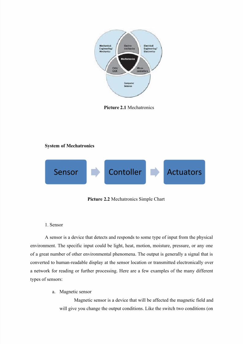
Picture 2.1 Mechatronics
System of Mechatronics
Picture 2.2 Mechatronics Simple Chart
1. Sensor
A sensor is a device that detects and responds to some type of input from the physical
environment. The specific input could be light, heat, motion, moisture, pressure, or any one
of a great number of other environmental phenomena. The output is generally a signal that is
converted to human-readable display at the sensor location or transmitted electronically over
a network for reading or further processing. Here are a few examples of the many different
types of sensors:
a. Magnetic sensor
Magnetic sensor is a device that will be affected the magnetic field andwill give you change the output conditions. Like the switch two conditions (on
Sensor Contoller Actuators

7/27/2019 Report Writing Group 7. Chapter 1 & 2
http://slidepdf.com/reader/full/report-writing-group-7-chapter-1-2 6/17
/ off) which is driven by a magnetic field around it. This sensor is usually
packaged in the form of empty packaging and free of dust, moisture, fumes or
vapors.
Picture 2.3 Magnetic Sensor
b. Light Sensor
Light sensor consists of 3 categories. Photovoltaic light sensor is a
device that converts light energy directly into electrical energy, with the
irradiation of light will cause the movement of electrons and produces a
voltage. Similarly, the photoconductive (fotoresistif) that will give you change
in resistance (resistance) in the cells, the higher the intensity of light received,
the smaller the value prisoners. While the Photoelectric sensor which is a work
based on the reflection principle due to changes in position / distance of a light
source (infrared or laser) or deflection targets, which consists of a light sourceand receiver.

7/27/2019 Report Writing Group 7. Chapter 1 & 2
http://slidepdf.com/reader/full/report-writing-group-7-chapter-1-2 7/17
Picture 2.4 Light Sensor
c. Pressure Sensor
This sensor has a wire strain gauge transducers, which convert
mechanical stress into electrical signals. Penginderaannya basic introduction
on the change in resistance (transducer) that change due to changes in long
and broad cross-section.
Picture 2.5 Pressure Sensor
7/27/2019 Report Writing Group 7. Chapter 1 & 2
http://slidepdf.com/reader/full/report-writing-group-7-chapter-1-2 8/17
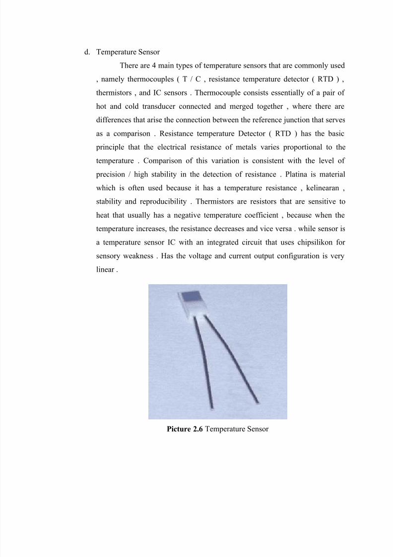
d. Temperature Sensor
There are 4 main types of temperature sensors that are commonly used
, namely thermocouples ( T / C , resistance temperature detector ( RTD ) ,
thermistors , and IC sensors . Thermocouple consists essentially of a pair of
hot and cold transducer connected and merged together , where there are
differences that arise the connection between the reference junction that serves
as a comparison . Resistance temperature Detector ( RTD ) has the basic
principle that the electrical resistance of metals varies proportional to the
temperature . Comparison of this variation is consistent with the level of
precision / high stability in the detection of resistance . Platina is material
which is often used because it has a temperature resistance , kelinearan ,
stability and reproducibility . Thermistors are resistors that are sensitive to
heat that usually has a negative temperature coefficient , because when the
temperature increases, the resistance decreases and vice versa . while sensor is
a temperature sensor IC with an integrated circuit that uses chipsilikon for
sensory weakness . Has the voltage and current output configuration is very
linear .
Picture 2.6 Temperature Sensor

7/27/2019 Report Writing Group 7. Chapter 1 & 2
http://slidepdf.com/reader/full/report-writing-group-7-chapter-1-2 9/17
2. Controller
The controller is a control element in a mechatronic system that receives input from
sensors and forward them to the actuators. One type of controller is the microcontroller.
Microcontroller is an IC with a very high density usually consists of CPU and RAM.
Most microcontrollers have instructions, manipulation of access to the input / output and the
process is streamlined.
Picture 2.7 PLC
Picture 2.8 Microcontroller

7/27/2019 Report Writing Group 7. Chapter 1 & 2
http://slidepdf.com/reader/full/report-writing-group-7-chapter-1-2 10/17
3. Actuators
Actuators are elements that receive and execute commands from the
controller. The concrete form of such actuators: electric motors, hydraulic tubes, pneumatic
tubes. Some examples and types of actuators including: Relay, Solenoid, and Motor DC.
Picture 2.9 Motor DC
Picture 2.10 Solenoid Valve

7/27/2019 Report Writing Group 7. Chapter 1 & 2
http://slidepdf.com/reader/full/report-writing-group-7-chapter-1-2 11/17
Mechatronic Applications
The following are some examples of applications of Mechatronics Systems :
1. Automatic Gate
Gate in the office or the company is now equipped automatic settings. If there is a
vehicle or a man who came in who had qualified the identification of the door will open, if
not eligible identification doors remain closed.
2. Refrigerators system (Refrigerant)
Refrigeration system or so-called refrigerator is one simple mechatronic applications
that synergize with the disciplines of energy conversion.
3. Air conditioning systems
Ac system is one of a mechatronic system applications in which there are control
systems, electronics and mechanics. Air space is controlled using the remote control (remote
control). At AC room, there are 2 very important component that must be there is the
condenser and compressor.
Definition and Component function
1. Belt Conveyor
Belt Conveyor is used is basically a fairly simple equipment. The tool consists of a
belt that is resistant to transport solid objects. Belts used in belt conveyor can be made from
various types of materials such as rubber, plastics, leather or metal depending on the type and
nature of the material to be transported. For transporting hot materials, used belts made of
metal that is resistant to heat.

7/27/2019 Report Writing Group 7. Chapter 1 & 2
http://slidepdf.com/reader/full/report-writing-group-7-chapter-1-2 12/17
Picture 2.11 Belt Conveyor
2. DC motors
Used as actuators on the conveyor belt, working principles related to sensors, objects
will move above the conveyor belt when detected by the sensor DC motor will automatically
perform the action that has been in the program in the microcontroller.
Picture 2.12 Motor DC
DC motors have two basic parts :
1 . Stationary part called the stator . The stator generates a magnetic field , both
generated from a coil ( electro magnet ) or a permanent magnet .
2 . Rotating part is called the rotor . The rotor in the form of a coil in which an
electrical current flows .
Electromagnetic force in a DC motor occurs when there is current flowing in
the conductor is in a magnetic field . The magnetic field itself is generated by a
permanent magnet . The lines of magnetic force flowing between two magnetic poles
of the north pole to the south pole . According to the law Lourentz force , the flowing
current in the conductor located in a magnetic field will cause the force . Force F
appears depends on the direction of the current I and the direction of the magnetic
field B.

7/27/2019 Report Writing Group 7. Chapter 1 & 2
http://slidepdf.com/reader/full/report-writing-group-7-chapter-1-2 13/17
WORKING PRINCIPLES OF DC MOTOR
DC motor is a type of motor that uses DC voltage as the energy source . By providing
different voltages at both terminals , the motor will rotate in one direction , and when the
polarity of the voltage is reversed then the direction of rotation of the motor will be reversed
as well . Polarity of the voltage applied to the two terminals determines the direction of
rotation of the motor while the big difference on both terminal voltage determines the motor
speed .
3. Relay
Relay is an electronic switch that can open or close the circuit by using control of
other electronic circuits . Composed of a relay coil , spring , switch ( connected to the spring )
and 2 electronic contacts ( normally closed and normally open )
• Normally closed ( NC ) : switch contact is connected to this when the relay is not
active or can be said to be a switch in the open condition .
• Normally Open ( NO ) : a switch connected to this contact when the relay is active
or can be said to be the switch in the closed condition .
Based on the basic principle of how it works , the relay can work because of the
magnetic field used to drive the switch . When the coil voltage supplied by the working
voltage relay will display the magnetic field in the coil due to the current flowing in the wire
windings . Electromagnetic coil that is as it would then pull the switch from NO to NC . If the
voltage to the coil is switched off then the magnetic field in the coil will be lost so that the
spring will pull the switch NC .
WORKING PRINCIPLES OF RELAY
Relay is a switch lever with wire windings on an iron rod (solenoid) nearby. When the
solenoid electrified, the lever would be interested because of the magnetic force that occurs in
the solenoid so that the switch contacts will close. By the time the flow is stopped, the
magnetic force will be lost, the lever will return to its original position and the contact switch
back terbuka.Relay typically used to drive a current / voltage is large (eg electrical equipment
4 amperes AC 220 V) using a current / voltage is small (eg 0.1 ampere 12 Volt DC). The

7/27/2019 Report Writing Group 7. Chapter 1 & 2
http://slidepdf.com/reader/full/report-writing-group-7-chapter-1-2 14/17
simplest relay is an electromechanical relays that provide mechanical movement while
getting electrical energy.
Picture 2.13 Relay
4. Microcontoller
Microcontroller is an IC with a very high density usually consists of CPU and RAM.
Average microntroler have instructions, manipulations access to input / output and efficient
process. Microcontroller is where all the controls on a circuit.
Picture 2.14 Microcontroller
5. LED
Basically, the LED component is a component made of semi-conductor diodes
capable of emitting light. LED is a product of the other findings after diode. The structure is
also similar to the diode.
7/27/2019 Report Writing Group 7. Chapter 1 & 2
http://slidepdf.com/reader/full/report-writing-group-7-chapter-1-2 15/17
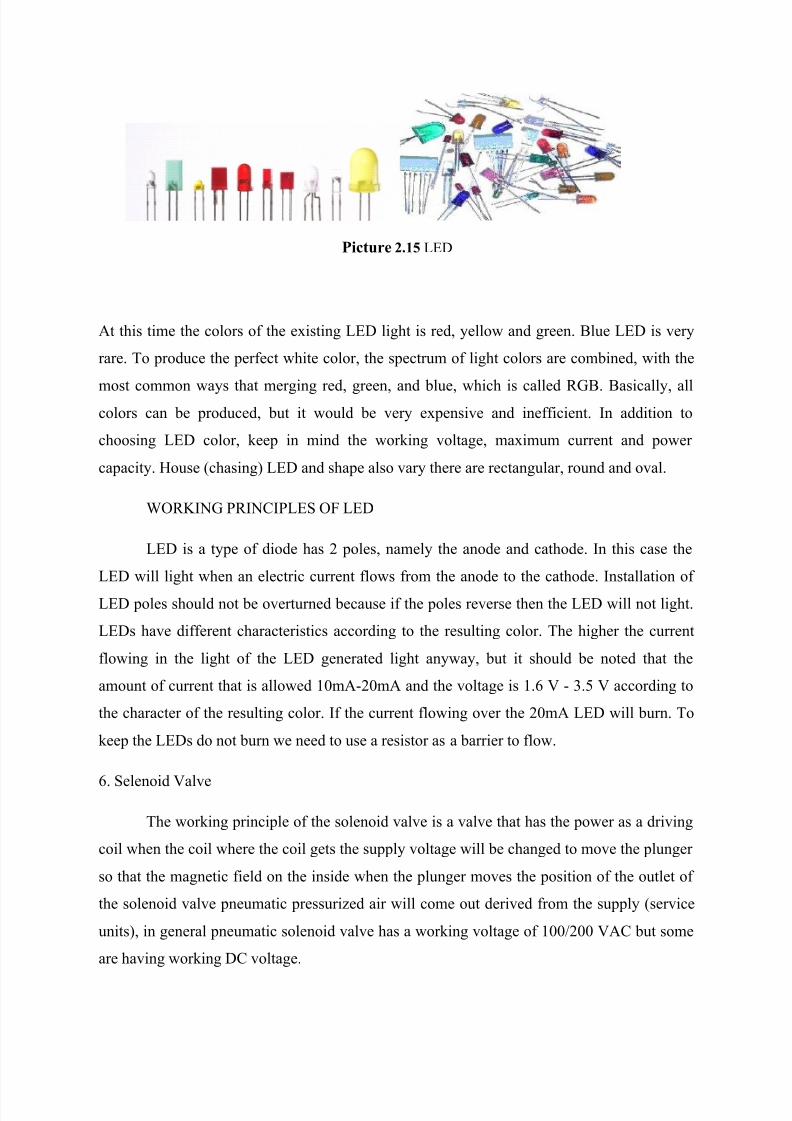
Picture 2.15 LED
At this time the colors of the existing LED light is red, yellow and green. Blue LED is very
rare. To produce the perfect white color, the spectrum of light colors are combined, with the
most common ways that merging red, green, and blue, which is called RGB. Basically, allcolors can be produced, but it would be very expensive and inefficient. In addition to
choosing LED color, keep in mind the working voltage, maximum current and power
capacity. House (chasing) LED and shape also vary there are rectangular, round and oval.
WORKING PRINCIPLES OF LED
LED is a type of diode has 2 poles, namely the anode and cathode. In this case the
LED will light when an electric current flows from the anode to the cathode. Installation of
LED poles should not be overturned because if the poles reverse then the LED will not light.
LEDs have different characteristics according to the resulting color. The higher the current
flowing in the light of the LED generated light anyway, but it should be noted that the
amount of current that is allowed 10mA-20mA and the voltage is 1.6 V - 3.5 V according to
the character of the resulting color. If the current flowing over the 20mA LED will burn. To
keep the LEDs do not burn we need to use a resistor as a barrier to flow.
6. Selenoid Valve
The working principle of the solenoid valve is a valve that has the power as a driving
coil when the coil where the coil gets the supply voltage will be changed to move the plunger
so that the magnetic field on the inside when the plunger moves the position of the outlet of
the solenoid valve pneumatic pressurized air will come out derived from the supply (service
units), in general pneumatic solenoid valve has a working voltage of 100/200 VAC but some
are having working DC voltage.

7/27/2019 Report Writing Group 7. Chapter 1 & 2
http://slidepdf.com/reader/full/report-writing-group-7-chapter-1-2 16/17
Picture 2.16 Solenoid Valve
7. Phototransistor
Phototransistor is a transistor that is designed to catch the light. Sensitivity
phototransistor is much better than the photodiode. Cause the flow of light received at the
base area of the phototransistor and produce current gain ranging from a hundred to a few
thousand times.
Picture 2.17 Phototransistor
8. Weight Sensors
Weight sensors are sensors used to measure the weight or load of an object. The
working principle of this sensor is to change the weight of the mechanical into electrical
signals. Weight is based on the principle that the resistance changes with the weight of anobject.

7/27/2019 Report Writing Group 7. Chapter 1 & 2
http://slidepdf.com/reader/full/report-writing-group-7-chapter-1-2 17/17
Picture 2.18 Weight Sensors