Report on Supplementary Geotechnical Investigation High ...
83
Report on Supplementary Geotechnical Investigation High School Redevelopment Argyle Street, Picton, NSW Prepared for Billard Leece Partnership Pty Ltd Project 34252.02 April 2018
Transcript of Report on Supplementary Geotechnical Investigation High ...

Report on Supplementary Geotechnical Investigation
High School Redevelopment Argyle Street, Picton, NSW
Prepared for Billard Leece Partnership Pty Ltd
Project 34252.02 April 2018

Document History
Document details Project No. 34252.02 Document No. R.004.Rev1 Document title Report on Supplementary Geotechnical Investigation
High School Redevelopment Site address Argyle Street, Picton, NSW Report prepared for Billard Leece Partnership Pty Ltd File name 34252.02.R.004.Rev1
Document status and review
Status Prepared by Reviewed by Date issued Revision 0 Rasoul Machiani Michael Thom 15 August 2017 Revision 1 Rasoul Machiani Michael Thom 4 April 2018
Distribution of copies
Status Electronic Paper Issued to Revision 0 1 0 Billard Leece Partnership Pty Ltd – Mr Shane Wood Revision 1 1 0 Billard Leece Partnership Pty Ltd – Mr Shane Wood
The undersigned, on behalf of Douglas Partners Pty Ltd, confirm that this document and all attached drawings, logs and test results have been checked and reviewed for errors, omissions and inaccuracies.
Signature Date
Author 4 April 2018
Reviewer 4 April 2018
Douglas Partners Pty Ltd ABN 75 053 980 117
www.douglaspartners.com.au 18 Waler Crescent
Smeaton Grange NSW 2567 Phone (02) 4647 0075
Fax (02) 4646 1886
Imie.StaTeresa
Typewritten text
pp for MT

Supplementary Geotechnical Investigation, Project 34252.02.R.004.Rev1 High School Redevelopment, Argyle Street, Picton, NSW April 2018
Table of Contents
Page
1. Introduction..................................................................................................................................... 1
2. Site Description .............................................................................................................................. 1
3. Regional Geology ........................................................................................................................... 2
4. Field Work Methods ....................................................................................................................... 2
5. Field Work Results ......................................................................................................................... 3
6. Laboratory Testing ......................................................................................................................... 3
6.1 Point Test Testing ................................................................................................................ 3
6.2 Soil Aggressivity ................................................................................................................... 3
7. Proposed Development .................................................................................................................. 4
8. Comments ...................................................................................................................................... 4 8.1 General ................................................................................................................................ 4
8.2 Subsurface Conditions and Rock Strength .......................................................................... 4
8.3 Foundations ......................................................................................................................... 5
8.4 Earthworks ........................................................................................................................... 6 8.4.1 Site Preparation ...................................................................................................... 6 8.4.2 Excavation ............................................................................................................... 7 8.4.3 Reuse of Excavated Materials ................................................................................ 8 8.4.4 Batter Slopes ........................................................................................................... 8
8.5 Excavation Support .............................................................................................................. 8
8.6 Earthquake Actions – Sub-soil Class .................................................................................11
9. Summary ...................................................................................................................................... 11
10. References ................................................................................................................................... 11
11. Limitations .................................................................................................................................... 12
Appendix A: About This Report Drawing 1
Appendix B: Borehole Logs (Bores 101 – 103)
Appendix C: Point Load Test Results
Appendix D: Aggressivity Test Results
Appendix E: Preliminary Geotechnical Investigation Report (34252.02.R.001)

Page 1 of 12
Supplementary Geotechnical Investigation, Project 34252.02.R.004.Rev1 High School Redevelopment, Argyle Street, Picton, NSW April 2018
Report on Supplementary Geotechnical Investigation High School Redevelopment Argyle Street, Picton, NSW 1. Introduction
This report presents the results of a supplementary geotechnical investigation undertaken for proposed redevelopment works within Picton High School at Argyle Street, Picton, NSW. The investigation was commissioned in an email dated 30June 2017 by Mr Shane Wood of Billard Leece Partnership Pty Ltd (Architects) and was undertaken in accordance with Douglas Partners' (DP) email proposal dated 8 June 2017. DP understands that the proposed redevelopment works will include the removal of some demountable buildings across the site and the construction of new teaching blocks, associated facilities and pavements. In the absence of conceptual design details, a preliminary geotechnical investigation was undertaken by DP consisting of ten test pits across the school site (Project No. 34252.02.P.001). A conceptual design drawing was provided for a supplementary geotechnical investigation that shows the location of proposed two and three storey buildings. The detailed design information of proposed new permanent buildings and cut-fill plans are yet to be finalized. The supplementary investigation included the drilling of cored boreholes and laboratory testing of selected samples. Details of the work undertaken and the results obtained are given within this report, together with comments relating to foundation design and earthworks. This report should be read in conjunction with the Preliminary Geotechnical Investigation Report. DP have undertaken Contamination Assessment (Project No. 34252.02.P.002) and Hazmat Survey (Project 34252.02.P.003) for the development, both of which have been reported separately. 2. Site Description
Picton High School is located approximately 90 km to the south-west of the Sydney CBD and is a rectangular shaped area of some 6 ha. Maximum north-south and east-west dimensions are approximately 200 m and 290 m respectively. The school site is bounded by Argyle Street to the west, residential properties to the north, and vacant land to the south and east. The school is currently occupied by 32 existing buildings comprising permanent and demountable structures of various sizes, a car park and playing fields. The school site is located within undulating rises with overall topographic relief of approximately 8 m from the highest parts (approximately RL218 m, relative to the Australian height datum) within the eastern and western portions to the lowest part (approximately RL 210 m) within the mid northern portion of the site. However, it has been partially levelled by cutting and filling to create flat platforms for the existing structures.

Page 2 of 12
Supplementary Geotechnical Investigation, Project 34252.02.R.004.Rev1 High School Redevelopment, Argyle Street, Picton, NSW April 2018
Approximately, two-thirds of the site is covered by the existing structures and carparks. These structures are generally located within the western portion of the site extending toward the middle portion. Two sporting fields are noted along the eastern and southern boundaries of the school site. At the time of the investigation, the vegetation across these open spaces was limited to well-maintained light grass. Medium size trees were present along the northern boundary with scattered trees noted between the existing buildings. 3. Regional Geology
Reference to the Wollongong-Port Hacking 1:100,000 Geological Sheet (Ref 1) indicates that the site is underlain by Ashfield Shale (mapping unit Rwa) of the Wianamatta Group of Triassic age. The Ashfield Shale typically comprises shale, siltstone, claystone and laminite with coal bands, all of which weathered to form clays of high plasticity. The results of the investigation were consistent with the geological mapping, with fine grained lithic sandstone of variable weathering and seams of siltstone encountered in the boreholes. 4. Field Work Methods
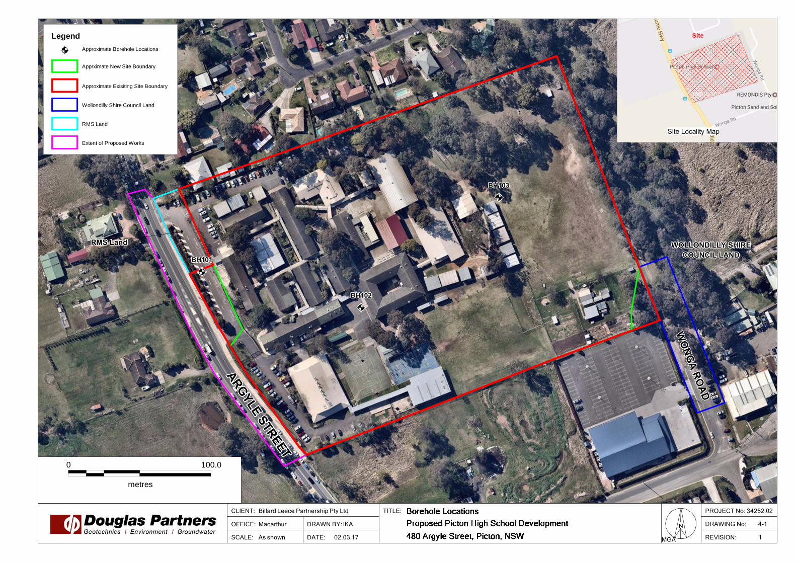
The field work comprised the drilling of three boreholes (Bores 101 – 103) to a depth of 8.0 m using a Christie Engineering trailer drilling rig using a combination of continuous solid flight augers with a nominal 100 mm diameter and ‘NMLC’ rotary coring techniques and water flush with steel casing to obtain continual rock core samples. Standard penetration tests (AS 1289.6.3.1) were also carried out at a depth of 1.0 m within all boreholes whilst augering. The standard penetration test procedure is given in the attached notes and the penetration ‘N’ value obtained during testing is shown on the borehole logs. The fieldwork was undertaken by a geotechnical engineer who logged the boreholes and collected disturbed samples to assist in strata identification and for laboratory testing. Following logging, testing and sampling, each borehole was backfilled and the ground surface reinstated to its previous level. The borehole locations were nominated by the client and located on site prior to the investigation using differential GPS unit for which an accuracy of ± 20 mm is typical. The location of boreholes are shown on Drawing 1 (Appendix A). The surface levels were obtained using the differential GPS unit. All field measurements and mapping for this project have been carried out using the Geodetic Datum of Australia 1994 (GDA94) and the Map Grid of Australia 1994 (MGA94 Zone 56). All reduced levels are given in relation to Australian Height Datum (AHD).

Page 3 of 12
Supplementary Geotechnical Investigation, Project 34252.02.R.004.Rev1 High School Redevelopment, Argyle Street, Picton, NSW April 2018
5. Field Work Results
The boreohle logs are included in Appendix B, and should be read in conjunction with the accompanying standard notes that define classification methods and descriptive terms. Relatively uniform conditions were encountered underlying the site with the general succession of strata is broadly summarised as follows:
• ASPHALTIC CONCRETE – 50 mm tick in Bores 101 & 102;
• TOPSOIL – brown silty clay (filling) to a depth of 0.1 m in Bore 103;
• FILLING –generally brown silty clay with some gravel to depths of 0.7 – 2.0 m in all boreholes;
• SILTY CLAY – very stiff grey/brown with seams of extremely weathered shale in Bores 101 & 102 to depths of 1.8 – 2.3 m; and
• BEDROCK – medium to high strength siltstone and sandstone at depths of 2.2 – 2.9 m, continued to the termination depth of boreholes.
No free groundwater was observed in the boreholes during auger drilling and for the short time that they were left open. The introduction of water into the boreholes during the rotary coring and the immediate backfilling of the test locations precluded any long-term observations of groundwater levels that might be present. It’s noted that groundwater levels are affected by factors such as weather conditions and can fluctuate with time. 6. Laboratory Testing
Selected samples from the test pits excavated for the preliminary geotechnical investigation were tested in the laboratory for measurement of field moisture content, Atterberg limits, shrink-swell and California bearing ratio (CBR). The results were provided in the preliminary geotechnical investigation report. 6.1 Point Test Testing
Selected rock core samples were tested in the laboratory for measurement of point load strength index (Is(50)) to estimate rock strength at variable depths. The detailed laboratory test report sheets are given in Appendix C and the values of Is(50) are shown on the borehole logs. 6.2 Soil Aggressivity
Selected samples from the boreholes were tested in the laboratory for aggressivity assessment by measuring pH, sulphates, chlorides, electrical conductivity. The detailed test report sheets are given in Appendix D, with the results summarised in Table 1.

Page 4 of 12
Supplementary Geotechnical Investigation, Project 34252.02.R.004.Rev1 High School Redevelopment, Argyle Street, Picton, NSW April 2018
Table 1: Results of Laboratory Testing – Aggressivity
Bore Depth (m) pH Chloride
(mg/kg) Sulphate (mg/kg)
EC (μS/cm) Material
101 1.0 5.9 10 21 36 Silty clay
101 3.1 9.0 37 <10 190 Siltstone
102 1.0 5.3 210 27 210 Silty Clay The exposure classification of the surface of concrete and steel piles was determined in accordance with AS 2159 – 1996 (Ref 2) as detailed in Table 6.4.2 (c) and Table 6.5.2 (c) which indicates the soils tested would be classified as "non aggressive" to concrete and steel. 7. Proposed Development
It is understood that the redevelopment works comprise the removal of selected demountable buildings within the site and the construction of new permanent teaching blocks. The proposed permanent buildings are understood to be two and three storey and are expected to be founded on piers constructed within good quality rock. The design loads and other detail design information of the structures are unknown at the time of writing this report. 8. Comments
8.1 General
Comments are provided in the following sections on development constraints related to geotechnical and geological factors to assist in the foundation design of the proposed two and three storey buildings. As detailed design of the proposed redevelopment works has not been undertaken, the comments given must also be considered as being preliminary in nature. Once details are available, they should be forwarded to DP for review to determine if comments given within this report are appropriate or require revision. 8.2 Subsurface Conditions and Rock Strength
The following comments are based on the surface and subsurface profiles encountered during the investigation and the results of laboratory testing of selected samples collected at the borehole locations. The boreholes have indicated that subsurface conditions underlying the site typically comprise asphalt or topsoil to a depth of 0.1 – 0.4 m underlain by filling to depths of 0.7 – 2.0 m. The filling is underlain by silty clays and low strength siltstone and sandstone to depths within the range 2.2 – 2.9 m. This in turn overlaid bedrock of medium to high strength condition to the final depth of boreholes. The bedrock from the cored boreholes has been classified in accordance with Reference 3 and depths/RLs of each rock class are summarised in Table 2.

Page 5 of 12
Supplementary Geotechnical Investigation, Project 34252.02.R.004.Rev1 High School Redevelopment, Argyle Street, Picton, NSW April 2018
Table 2: Depth/Level of Rock Classes
Bore RL Depth (m) Thickness (m)
Rock Class
Sandstone Shale
101 Surface Level: 217.7m AHD
214.7 – 214.0 0.7 - IV
214.0 – 212.0 2.0 - III
212.0 – 209.6 2.4 III -
102 Surface Level: 214.6m AHD
212.3 – 211.5 0.8 IV -
211.5 – 206.5 5.0 III -
103 Surface Level: 215.6m AHD
213.4 – 212.9 0.5 IV -
212.9 – 207.5 5.4 III -
The cored borehole logs indicate that the rock structure is mainly governed by horizontal to sub-horizontal (0º – 10º) bedding and horizontal to steeply-inclined (0° – 45°) jointing observed mainly in fractured siltstone. The fracture spacings shown on the recovered core samples show ‘highly fragmented’ siltstone to depths of 5.6 m in Bore 101 (Approx. RL 212 m AHD). Medium strength sandstone was encountered in the boreholes at RL’s 212 – 213 m AHD and identified as ‘moderately fractured’ to ‘unbroken’ (fracture spacings of 100 – 1000 mm). 8.3 Foundations
The results of the investigation indicates that good quality weathered rock will be expected at depths ranging from 2.5 – 4.0 m at the borehole locations, and hence, pending the required excavation depth, deep foundations in the form of bored or driven piles would be suitable options to accommodate the loads of the proposed two or three storey buildings. The use of shallow footings may only be justified for the lightly loaded structures founded in controlled filling or stiff natural clay. Based on the results of the field investigation and laboratory testing, retaining wall and building footings could be proportioned using the maximum design parameters presented in Table 3. The footing recommendations and design parameters for any given strata will need to be confirmed following the completion of design stage when the final excavation depth, footing size and design loads are specified.

Page 6 of 12
Supplementary Geotechnical Investigation, Project 34252.02.R.004.Rev1 High School Redevelopment, Argyle Street, Picton, NSW April 2018
Table 3: Estimated Design Parameters
Material
Ultimate Base
Bearing Pressures
(kPa) (1)
Ultimate Shaft
Adhesion Pressures
(kPa) (2)
Allowable Base
Bearing Pressures
(kPa) (3)
Allowable Shaft
Adhesion Pressures
(kPa)
Allowable Lateral
Resistance (kPa)
Controlled fill - - 100 - -
Very stiff to hard clay - - 200 - -
Sandstone
Class V 5000 200 1200 100 400
Class IV 8000 400 3500 350 1200
Class III 25000 1000 6000 600 2000
Shale
Class V 3000 100 700 70 200
Class IV 6000 150 1000 100 300
Class III 20000 750 3500 350 1200 Notes (1) The values are in accordance with Pells et al- 1998 (Ref3);
(2) Ultimate values occur at large settlements (generally >5% of the minimum footing width); (3) Values can only be adopted for clean sockets of roughness category R2 or better. Values may need to be
reduced to account for smear; (4) Value for rock based on settlements of <1% of minimum footing width.
Base bearing and shaft adhesion values have also been provided for Limit State design. The geotechnical strength reduction factor Φg of 0.45 shall be applied in accordance with AS2159-2009, Table 4.3.2 based on the available information. Reference should be made to the borehole logs (Appendix B) and Table 2 with respect to the depth/levels of the various bearing strata 8.4 Earthworks
It is considered that some bulk earthworks including the removal of existing structures and underlying moisture affected or unsuitable material will be expected. The final earthworks plans have not been finalized at the time of preparing this report. It can be inferred from the conceptual design drawing that a lower ground floor is incorporated in the proposed buildings. Filling is expected to be limited to grading the site surface for light demountable buildings, pavement construction and installation of services.
8.4.1 Site Preparation
It is recommended that all filling be placed and compacted in accordance with Level 1 requirements (AS3798 – 2007). To prepare the site for the construction of new buildings, the following procedures are suggested.
• Stripping of vegetation and organic topsoils (to expected maximum depths of 0.3 m) and separately stockpiled for use in landscaping or removed off site;
• Stripping of uncontrolled fill and unsuitable material within the footprint of the proposed buildings and pavements. Inspection of the stripped surface by a geotechnical engineer;

Page 7 of 12
Supplementary Geotechnical Investigation, Project 34252.02.R.004.Rev1 High School Redevelopment, Argyle Street, Picton, NSW April 2018
• Compaction of the exposed surface with at least of 8 passes of a 12 tonne (minimum dead weight) roller, followed by test rolling in the presence of a geotechnical engineer. Where soft spots are identified, they should be excavated and then backfilled using a suitable granular material. Additional filling may also be required to elevate building platforms. All filling should be placed in 250 mm (loose thickness) layers and compacted with placement moisture contents within the range of -2% to +2% of OMC in order to limit surface deflection during proof rolling.
• Surface drainage should be maintained at all times by adopting appropriate cross-falls across the site. Surface drainage should be installed as soon as is practicable in order to capture and remove surface flows to prevent erosion and softening of the exposed surface.
Filling delivered to site must be approved by the geotechnical consultant prior to delivery to site. Highly reactive clay filling should be avoided. Site observations and laboratory test results have indicated the presence of high plasticity silty clays in some areas which could be adversely affected by inclement weather. Whilst these soils are typically of a stiff to very stiff consistency when dry, they can rapidly lose strength during rainfall and subsequent partial saturation and result in difficult trafficability conditions. Conventional sediment and erosion control measures should be implemented during the construction phase, with exposed surfaces to be topsoiled and vegetated as soon as practicable following the completion of earthworks.
8.4.2 Excavation
All topsoil, filling, natural soils and bedrock up to very low to low strength should be readily removed using a conventional medium sized excavator fitted with a toothed bucket possibly with some light ripping in the weathered bedrock. These conditions were generally encountered to depths of about 2.0 – 3.0 m within all borehole locations The excavation is expected to include any moisture affected material within the footprint of demolished buildings and then extend further to the design level at the base of the lower ground level. Where low to medium strength rock were encountered, these areas will, for the most part, be adequately removed during bulk earthworks using a large excavator with some light to medium ripping. However, larger plant may provide greater excavation efficiency particularly during drilling of pier foundations. Medium to high strength rock will offer greater resistance to light ripping. These areas will require pneumatic/hydraulic hammering equipment in combination with rock sawing and/or grinding to achieve the required cut depths. Due to the proximity of surrounding buildings and presence of filling at shallow depth, the vibration resulting from the excavation could cause damage to the underground services or demountable and brick structures. It is recommended, if the use of percussive equipment is required within 40 m of any vibration sensitive structures, vibration monitoring should be undertaken. If the monitoring indicates unacceptable levels of vibration, then the use of non-percussive (i.e.: rock sawing and ripping) excavation methods will be required. This requirement however, will need to be determined on site once the details of the bulk earthworks and proposed excavation equipment are known.

Page 8 of 12
Supplementary Geotechnical Investigation, Project 34252.02.R.004.Rev1 High School Redevelopment, Argyle Street, Picton, NSW April 2018
Anticipated equipments required for excavations are given as a guide only. Rock strength and quality are expected to vary within the footprint of the proposed buildings. Assessment of excavation difficulties are best determined by intending contractors based on inspection of the core samples, the equipment they have at their disposal and the experience of the operators. For information on soil and rock types and indicative strength, reference must be made to the individual logs which are included in Appendix B.
8.4.3 Reuse of Excavated Materials
Generally, the filling, natural clays and bedrock of up to low strength encountered during the investigation, will be suitable for reuse as engineered filling within the site. The material should not contain any particle sizes greater than 150 mm as these may cause inadequate compaction, and should not contain silts due to their propensity for saturation and erosion. It is expected that the extremely weathered or low strength rock should readily break down beneath the weight of the rollers. However, bedrock of medium strength or higher may potentially need to be crushed using a rock crusher. Topsoil and other deleterious materials will not be suitable as a fill material but could be stockpiled for potential use in landscaping or alternatively, removal from site.
8.4.4 Batter Slopes
While cut slopes within the clays may often stand vertically and unsupported (provided no nearby structures are present) for short periods of time, they will rapidly lose strength upon exposure to weather. A maximum batter slope of 1(H):1(V) is recommended for unsurcharged temporary slopes in stiff clays. The maximum batter slope should be reduced to 3(H):1(V) for temporary batters in uncontrolled filling. Where the slopes are to be vegetated to prevent erosion, a maximum final batter slope of 3(H):1(V) is recommended. If batters greater than 4 m in height are required, the inclusion of a 3 m wide intermediate bench every 5 m in height, is recommended to reduce the effects of scour and erosion. Where filling batters are formed, similar parameters to those recommended for cut slopes can be adopted. However, it is recommended that whilst the slope is being formed the batters should be over-filled in near-horizontal lifts and cut back to form the design grades. 8.5 Excavation Support
Once bulk excavations are required, temporary or permanent batters at recommended batter angles may not be feasible due to insufficient space for batters adjacent of the excavation. The design of shoring will therefore be required for subsurface materials as batters steeper that those suggested in Section 8.4 are not expected to remain stable for a long period of time. The design should take account of the lateral loads due to adjacent structures.

Page 9 of 12
Supplementary Geotechnical Investigation, Project 34252.02.R.004.Rev1 High School Redevelopment, Argyle Street, Picton, NSW April 2018
Pending the final excavation depth, the following options may be adopted for retaining the excavations in this project. The feasible options would include either anchored soldier piles (drilled at maximum 2.4 m spacings) with close shuttering / shotcrete infill panels or contiguous piling. In the absence of details of adjacent footings being available, contiguous piles should be used for excavations adjacent to neighbouring buildings. Contiguous piling is the cheapest form of concrete pile wall, however, is not a water retaining structure and may not be suitable for any material due to gaps between piles. Excavation of panels for shotcreting at anchored soldier piles option should be staged to allow a hit and miss approach with the first panel extending no more than 1.0 m below the base of the adjacent building foundation, including the reinforcement overlap. The next row of panels should not exceed 1.5 m with subsequent panels not exceeding 2 m in height. Drainage is normally provided behind shotcrete walls. The sprayed concrete wall should provide adequate structural support, however it may be appropriate to install a false wall (single brickwork or block work) for aesthetic purposes and to avoid dampness. Care should be exercised in construction to ensure that anchors are installed progressively with excavation (and stressed up) and that the shotcreting is carried out at regular intervals to limit the exposed sections. The first row of anchors should be installed as high as possible and stressed up to 80% of its working load prior to excavation of the next row of panels. A high capacity piling rig will be required to penetrate the high strength rock. Otherwise, the piers may refuse in the high strength rock, well above the excavation levels and additional anchors may need to be installed in the toe of each pier to provide support/restraint of the structure and rock mass. As a result of moderately to steeply-inclined jointing especially in fractured siltstone and potential for 'wedge-type' failures within the batters, allowance will also need to be made for the support of the fractured rock where contiguous walling is not installed. The support requirements will depend on a number of factors including extent of disturbance during excavation; orientation (bearing), persistence (lateral continuity) and spacing (horizontal separation) of jointing; clay infilling of open jointing; and groundwater. As such, detailed design should be reviewed and verified by DP to ensure the allowance has been made for variable subsurface strata encountered. As a guide, in addition to the soldier piles, preliminary design of infilled panel sections should allow for the application of a steel mesh-reinforced shotcrete layer with a minimum nominal thickness of 150 mm where permanent support is required or 75 mm for temporary support. Due to the highly fractured nature of the rock stratum at shallow depth, the installation of a rock bolts may be considered to support the temporary excavations batters based on inspections carried out by an engineering geologist. The final required bolt lengths can only be determined following assessment of fracture characteristics observed in the face. Earth pressures acting on multi-anchored shoring structures and retaining walls can be estimated on the basis of a trapezoidal pressure distribution (i.e.: triangular to 0.25 H, uniform from 0.25 H to 0.75 H and triangular decreasing to zero from 0.75 H to H) with depth using appropriate values of bulk density and active (Ka) or 'at rest' (Ko) lateral earth pressure coefficients as set out in Table 4.

Page 10 of 12
Supplementary Geotechnical Investigation, Project 34252.02.R.004.Rev1 High School Redevelopment, Argyle Street, Picton, NSW April 2018
Table 4: Suggested Lateral Earth Pressure Design Parameters – Retaining Structures
Retained Material Bulk Density (kN/m3) K0
Ka
Short Term Long Term
Stiff to hard clay and extremely weathered rock 20 0.6 0.25 0.3
Very low strength siltstone and sandstone 22 0.45 0.3 0.35
Medium strength or greater siltstone and sandstone 22 - 10 kPa* 10 kPa*
* A uniform pressure of 10 kPa should be adopted for the support of the medium strength sandstone to account for possible defects, but subject to inspection during the early stages of excavation to confirm bedding/jointing and revision of lateral restraint, if appropriate. 'At rest' pressure coefficients are appropriate where support must be provided to boundaries and where movement intolerant services or adjacent structures are present. Surcharge lateral pressure due to any adjacent structure will also need to be taken into account where the footings found on low strength or weaker rock or unfavourably orientated jointing is encountered. The current investigation is not suggesting any indication of groundwater table to the limit of investigation. In the event that, tanked basement is required for this project, full hydrostatic pressure should be allowed for in design. As such, densities of the retained soils can be appropriately reduced to the buoyant values. Where applicable, superimposed surcharge loads due to adjacent driveways and developments should also be accommodated in the design of such structures. Where appropriate, lateral restraint may also be developed by embedding piles below the base of the excavation and developing passive pressure. Suggested ultimate passive resistance values are given in Table 5 may be adopted below one pile diameter beneath the bulk excavation level and should incorporate a factor of safety to limit wall movement. Table 5: Suggested Ultimate Passive Pressure Values
Material Ultimate Passive Pressure (kPa)
Extremely low and very low strength siltstone 300
Low strength siltstone and sandstone 1200
Medium or greater strength siltstone and sandstone 4000
Where engineer-designed retaining walls are proposed, the following measures should be incorporated into the design:
• Backfilling of the void between the wall and the slope using imported, free draining granular material connected into a drainage pipe at the base of the wall;
• Capping of the backfill (where exposed) with compacted clay or concrete to prevent surface runoff entering the backfill;
• Provision of an open drain to collect and divert surface runoff from ponding above the wall;

Page 11 of 12
Supplementary Geotechnical Investigation, Project 34252.02.R.004.Rev1 High School Redevelopment, Argyle Street, Picton, NSW April 2018
• For horizontal backfill or retained soils, design based on an average bulk unit weight for retained material of 20 kN/m3 and on a triangular earth pressure distribution based on an active earth pressure coefficient of (Ka) 0.3 for compacted filling and natural clay where no movement sensitive structures are located within a horizontal distance of 2H (where H is the vertical height of the retained zone) of the rear of the wall;
• Where there are movement sensitive structures located within the abovementioned critical zone, an at rest pressure coefficient (K0) of 0.6 should be adopted; and
• If hydrostatic pressures are allowed, soil densities could be reduced to the buoyant values. If an adequate drainage medium is not provided behind the retaining wall, then hydrostatic pressures must be incorporated within the design with soil parameters reduced to their buoyant values. 8.6 Earthquake Actions – Sub-soil Class
The site stratigraphy comprises minor filling and topsoil underlain by stiff to hard silty clays, overlying bedrock at depths ranging from 1.8 m to 2.3 m within the footprint of the proposed structure. Therefore, the site's sub-soil class when assessed in accordance with AS 1170.4 – 2007 (Ref 4) is considered a rock site and a classification of Class Be is suggested. 9. Summary
The investigation included the drilling of three cored boreholes to a depth of 8.0 m within the proposed school site at the nominated locations by the client. The boreholes have indicated that subsurface conditions underlying the site generally comprise variable depths of filling and topsoil overlying silty clay and clay of very stiff to hard consistency. Rock was encountered in all boreholes on first contact at depths of between within the range 1.8 m to 2.3 m. Bearing capacity recommendations are provided in Section 8.3. The site preparation, earthworks and excavation support recommendations are to be undertaken in accordance with Sections 8.4 and 8.5. Consideration must be given to the preliminary nature of the investigation and potential for variability in the subsurface condition across the site. Once design is suitably advanced, DP must review the plans to determine if the comments given within are appropriate or if additional investigations are required. 10. References
1. Geology of 1:100 000 Wollongong – Port Hacking Geological Series Sheet No 9029 – 9129, Dept of Mines, (1985).
2. Australian Standard AS 2159 – 2009 "Piling – Design and Installation".
3. Foundations on Shales and Sandstones in the Sydney Region, Pells et al, Australian Geomechanics Journal (1998).
4. AS 1170.4 – 2007, "Structural Design Actions – Part 4: Earthquake Actions in Australia".

Page 12 of 12
Supplementary Geotechnical Investigation, Project 34252.02.R.004.Rev1 High School Redevelopment, Argyle Street, Picton, NSW April 2018
5. AS 1170.4 – 1993, "Structural Design Actions – Part 4: Earthquake Actions in Australia".
6. AS 3798 – 2007, "Guidelines on Earthworks for Commercial and Residential Developments". 11. Limitations
Douglas Partners Pty Ltd (DP) has prepared this report (or services) for the proposed redevelopment works at Picton High School in accordance with DP’s email proposal dated 8 June 2017 and acceptance received from Mr Shane Wood dated 30 June 2017. The work was carried out under projects General Terms and Conditions. This report is provided for the exclusive use of Billard Leece Partnership Pty Ltd for this project only and for the purposes as described in the report. It should not be used for other projects or by a third party. Any party so relying upon this report beyond its exclusive use and purpose as stated above, and without the express written consent of DP, does so entirely at its own risk and without recourse to DP for any loss or damage. In preparing this report DP has necessarily relied upon information provided by the client and/or their agents. The results provided in the report are indicative of the sub-surface conditions on the site only at the specific sampling and/or testing locations, and then only to the depths investigated and at the time the work was carried out. Sub-surface conditions can change abruptly due to variable geological processes and also as a result of human influences. Such changes may occur after DP’s field testing has been completed. DP’s advice is based upon the conditions encountered during this investigation. The accuracy of the advice provided by DP in this report may be affected by undetected variations in ground conditions across the site between and beyond the sampling and/or testing locations. This report must be read in conjunction with all of the attached and should be kept in its entirety without separation of individual pages or sections. DP cannot be held responsible for interpretations or conclusions made by others unless they are supported by an expressed statement, interpretation, outcome or conclusion stated in this report. This report, or sections from this report, should not be used as part of a specification for a project, without review and agreement by DP. This is because this report has been written as advice and opinion rather than instructions for construction. The contents of this report do not constitute formal design components such as are required, by the Health and Safety Legislation and Regulations, to be included in a Safety Report specifying the hazards likely to be encountered during construction and the controls required to mitigate risk. This design process requires risk assessment to be undertaken, with such assessment being dependent upon factors relating to likelihood of occurrence and consequences of damage to property and to life. This, in turn, requires project data and analysis presently beyond the knowledge and project role respectively of DP. DP may be able, however, to assist the client in carrying out a risk assessment of potential hazards contained in the Comments section of this report, as an extension to the current scope of works, if so requested, and provided that suitable additional information is made available to DP. Any such risk assessment would, however, be necessarily restricted to the geotechnical/groundwater components set out in this report and to their application by the project designers to project design, construction, maintenance and demolition.
Douglas Partners Pty Ltd

Appendix A
About This Report Drawing 1

July 2010
Introduction These notes have been provided to amplify DP's report in regard to classification methods, field procedures and the comments section. Not all are necessarily relevant to all reports. DP's reports are based on information gained from limited subsurface excavations and sampling, supplemented by knowledge of local geology and experience. For this reason, they must be regarded as interpretive rather than factual documents, limited to some extent by the scope of information on which they rely. Copyright This report is the property of Douglas Partners Pty Ltd. The report may only be used for the purpose for which it was commissioned and in accordance with the Conditions of Engagement for the commission supplied at the time of proposal. Unauthorised use of this report in any form whatsoever is prohibited. Borehole and Test Pit Logs The borehole and test pit logs presented in this report are an engineering and/or geological interpretation of the subsurface conditions, and their reliability will depend to some extent on frequency of sampling and the method of drilling or excavation. Ideally, continuous undisturbed sampling or core drilling will provide the most reliable assessment, but this is not always practicable or possible to justify on economic grounds. In any case the boreholes and test pits represent only a very small sample of the total subsurface profile. Interpretation of the information and its application to design and construction should therefore take into account the spacing of boreholes or pits, the frequency of sampling, and the possibility of other than 'straight line' variations between the test locations. Groundwater Where groundwater levels are measured in boreholes there are several potential problems, namely: • In low permeability soils groundwater may
enter the hole very slowly or perhaps not at all during the time the hole is left open;
• A localised, perched water table may lead to an erroneous indication of the true water table;
• Water table levels will vary from time to time with seasons or recent weather changes. They may not be the same at the time of construction as are indicated in the report; and
• The use of water or mud as a drilling fluid will mask any groundwater inflow. Water has to be blown out of the hole and drilling mud must first be washed out of the hole if water measurements are to be made.
More reliable measurements can be made by installing standpipes which are read at intervals over several days, or perhaps weeks for low permeability soils. Piezometers, sealed in a particular stratum, may be advisable in low permeability soils or where there may be interference from a perched water table. Reports The report has been prepared by qualified personnel, is based on the information obtained from field and laboratory testing, and has been undertaken to current engineering standards of interpretation and analysis. Where the report has been prepared for a specific design proposal, the information and interpretation may not be relevant if the design proposal is changed. If this happens, DP will be pleased to review the report and the sufficiency of the investigation work. Every care is taken with the report as it relates to interpretation of subsurface conditions, discussion of geotechnical and environmental aspects, and recommendations or suggestions for design and construction. However, DP cannot always anticipate or assume responsibility for: • Unexpected variations in ground conditions.
The potential for this will depend partly on borehole or pit spacing and sampling frequency;
• Changes in policy or interpretations of policy by statutory authorities; or
• The actions of contractors responding to commercial pressures.
If these occur, DP will be pleased to assist with investigations or advice to resolve the matter.

July 2010
Site Anomalies In the event that conditions encountered on site during construction appear to vary from those which were expected from the information contained in the report, DP requests that it be immediately notified. Most problems are much more readily resolved when conditions are exposed rather than at some later stage, well after the event. Information for Contractual Purposes Where information obtained from this report is provided for tendering purposes, it is recommended that all information, including the written report and discussion, be made available. In circumstances where the discussion or comments section is not relevant to the contractual situation, it may be appropriate to prepare a specially edited document. DP would be pleased to assist in this regard and/or to make additional report copies available for contract purposes at a nominal charge. Site Inspection The company will always be pleased to provide engineering inspection services for geotechnical and environmental aspects of work to which this report is related. This could range from a site visit to confirm that conditions exposed are as expected, to full time engineering presence on site.

July 2010
Rock Strength Rock strength is defined by the Point Load Strength Index (Is(50)) and refers to the strength of the rock substance and not the strength of the overall rock mass, which may be considerably weaker due to defects. The test procedure is described by Australian Standard 4133.4.1 - 1993. The terms used to describe rock strength are as follows:
Term Abbreviation Point Load Index Is(50) MPa
Approx Unconfined Compressive Strength MPa*
Extremely low EL <0.03 <0.6
Very low VL 0.03 - 0.1 0.6 - 2
Low L 0.1 - 0.3 2 - 6
Medium M 0.3 - 1.0 6 - 20
High H 1 - 3 20 - 60
Very high VH 3 - 10 60 - 200
Extremely high EH >10 >200 * Assumes a ratio of 20:1 for UCS to Is(50)
Degree of Weathering The degree of weathering of rock is classified as follows:
Term Abbreviation Description Extremely weathered EW Rock substance has soil properties, i.e. it can be remoulded
and classified as a soil but the texture of the original rock is still evident.
Highly weathered HW Limonite staining or bleaching affects whole of rock substance and other signs of decomposition are evident. Porosity and strength may be altered as a result of iron leaching or deposition. Colour and strength of original fresh rock is not recognisable
Moderately weathered
MW Staining and discolouration of rock substance has taken place
Slightly weathered SW Rock substance is slightly discoloured but shows little or no change of strength from fresh rock
Fresh stained Fs Rock substance unaffected by weathering but staining visible along defects
Fresh Fr No signs of decomposition or staining Degree of Fracturing The following classification applies to the spacing of natural fractures in diamond drill cores. It includes bedding plane partings, joints and other defects, but excludes drilling breaks.
Term Description Fragmented Fragments of <20 mm Highly Fractured Core lengths of 20-40 mm with some fragments Fractured Core lengths of 40-200 mm with some shorter and longer sections Slightly Fractured Core lengths of 200-1000 mm with some shorter and loner sections Unbroken Core lengths mostly > 1000 mm

July 2010
Rock Quality Designation The quality of the cored rock can be measured using the Rock Quality Designation (RQD) index, defined as:
RQD % = cumulative length of 'sound' core sections ≥ 100 mm long total drilled length of section being assessed
where 'sound' rock is assessed to be rock of low strength or better. The RQD applies only to natural fractures. If the core is broken by drilling or handling (i.e. drilling breaks) then the broken pieces are fitted back together and are not included in the calculation of RQD. Stratification Spacing For sedimentary rocks the following terms may be used to describe the spacing of bedding partings:
Term Separation of Stratification Planes Thinly laminated < 6 mm Laminated 6 mm to 20 mm Very thinly bedded 20 mm to 60 mm Thinly bedded 60 mm to 0.2 m Medium bedded 0.2 m to 0.6 m Thickly bedded 0.6 m to 2 m Very thickly bedded > 2 m

July 2010
Sampling Sampling is carried out during drilling or test pitting to allow engineering examination (and laboratory testing where required) of the soil or rock. Disturbed samples taken during drilling provide information on colour, type, inclusions and, depending upon the degree of disturbance, some information on strength and structure. Undisturbed samples are taken by pushing a thin-walled sample tube into the soil and withdrawing it to obtain a sample of the soil in a relatively undisturbed state. Such samples yield information on structure and strength, and are necessary for laboratory determination of shear strength and compressibility. Undisturbed sampling is generally effective only in cohesive soils. Test Pits Test pits are usually excavated with a backhoe or an excavator, allowing close examination of the in-situ soil if it is safe to enter into the pit. The depth of excavation is limited to about 3 m for a backhoe and up to 6 m for a large excavator. A potential disadvantage of this investigation method is the larger area of disturbance to the site. Large Diameter Augers Boreholes can be drilled using a rotating plate or short spiral auger, generally 300 mm or larger in diameter commonly mounted on a standard piling rig. The cuttings are returned to the surface at intervals (generally not more than 0.5 m) and are disturbed but usually unchanged in moisture content. Identification of soil strata is generally much more reliable than with continuous spiral flight augers, and is usually supplemented by occasional undisturbed tube samples. Continuous Spiral Flight Augers The borehole is advanced using 90-115 mm diameter continuous spiral flight augers which are withdrawn at intervals to allow sampling or in-situ testing. This is a relatively economical means of drilling in clays and sands above the water table. Samples are returned to the surface, or may be collected after withdrawal of the auger flights, but they are disturbed and may be mixed with soils from the sides of the hole. Information from the drilling (as distinct from specific sampling by SPTs or undisturbed samples) is of relatively low
reliability, due to the remoulding, possible mixing or softening of samples by groundwater. Non-core Rotary Drilling The borehole is advanced using a rotary bit, with water or drilling mud being pumped down the drill rods and returned up the annulus, carrying the drill cuttings. Only major changes in stratification can be determined from the cuttings, together with some information from the rate of penetration. Where drilling mud is used this can mask the cuttings and reliable identification is only possible from separate sampling such as SPTs. Continuous Core Drilling A continuous core sample can be obtained using a diamond tipped core barrel, usually with a 50 mm internal diameter. Provided full core recovery is achieved (which is not always possible in weak rocks and granular soils), this technique provides a very reliable method of investigation. Standard Penetration Tests Standard penetration tests (SPT) are used as a means of estimating the density or strength of soils and also of obtaining a relatively undisturbed sample. The test procedure is described in Australian Standard 1289, Methods of Testing Soils for Engineering Purposes - Test 6.3.1. The test is carried out in a borehole by driving a 50 mm diameter split sample tube under the impact of a 63 kg hammer with a free fall of 760 mm. It is normal for the tube to be driven in three successive 150 mm increments and the 'N' value is taken as the number of blows for the last 300 mm. In dense sands, very hard clays or weak rock, the full 450 mm penetration may not be practicable and the test is discontinued. The test results are reported in the following form. • In the case where full penetration is obtained
with successive blow counts for each 150 mm of, say, 4, 6 and 7 as:
4,6,7 N=13
• In the case where the test is discontinued before the full penetration depth, say after 15 blows for the first 150 mm and 30 blows for the next 40 mm as:
15, 30/40 mm

July 2010
The results of the SPT tests can be related empirically to the engineering properties of the soils. Dynamic Cone Penetrometer Tests / Perth Sand Penetrometer Tests Dynamic penetrometer tests (DCP or PSP) are carried out by driving a steel rod into the ground using a standard weight of hammer falling a specified distance. As the rod penetrates the soil the number of blows required to penetrate each successive 150 mm depth are recorded. Normally there is a depth limitation of 1.2 m, but this may be extended in certain conditions by the use of extension rods. Two types of penetrometer are commonly used. • Perth sand penetrometer - a 16 mm diameter
flat ended rod is driven using a 9 kg hammer dropping 600 mm (AS 1289, Test 6.3.3). This test was developed for testing the density of sands and is mainly used in granular soils and filling.
• Cone penetrometer - a 16 mm diameter rod with a 20 mm diameter cone end is driven using a 9 kg hammer dropping 510 mm (AS 1289, Test 6.3.2). This test was developed initially for pavement subgrade investigations, and correlations of the test results with California Bearing Ratio have been published by various road authorities.

July 2010
Description and Classification Methods The methods of description and classification of soils and rocks used in this report are based on Australian Standard AS 1726, Geotechnical Site Investigations Code. In general, the descriptions include strength or density, colour, structure, soil or rock type and inclusions. Soil Types Soil types are described according to the predominant particle size, qualified by the grading of other particles present:
Type Particle size (mm) Boulder >200 Cobble 63 - 200 Gravel 2.36 - 63 Sand 0.075 - 2.36 Silt 0.002 - 0.075 Clay <0.002
The sand and gravel sizes can be further subdivided as follows:
Type Particle size (mm) Coarse gravel 20 - 63 Medium gravel 6 - 20 Fine gravel 2.36 - 6 Coarse sand 0.6 - 2.36 Medium sand 0.2 - 0.6 Fine sand 0.075 - 0.2
The proportions of secondary constituents of soils are described as:
Term Proportion Example And Specify Clay (60%) and
Sand (40%) Adjective 20 - 35% Sandy Clay Slightly 12 - 20% Slightly Sandy
Clay With some 5 - 12% Clay with some
sand With a trace of 0 - 5% Clay with a trace
of sand
Definitions of grading terms used are: • Well graded - a good representation of all
particle sizes • Poorly graded - an excess or deficiency of
particular sizes within the specified range • Uniformly graded - an excess of a particular
particle size • Gap graded - a deficiency of a particular
particle size with the range Cohesive Soils Cohesive soils, such as clays, are classified on the basis of undrained shear strength. The strength may be measured by laboratory testing, or estimated by field tests or engineering examination. The strength terms are defined as follows:
Description Abbreviation Undrained shear strength
(kPa) Very soft vs <12 Soft s 12 - 25 Firm f 25 - 50 Stiff st 50 - 100 Very stiff vst 100 - 200 Hard h >200
Cohesionless Soils Cohesionless soils, such as clean sands, are classified on the basis of relative density, generally from the results of standard penetration tests (SPT), cone penetration tests (CPT) or dynamic penetrometers (PSP). The relative density terms are given below:
Relative Density
Abbreviation SPT N value
CPT qc value (MPa)
Very loose vl <4 <2 Loose l 4 - 10 2 -5 Medium dense
md 10 - 30 5 - 15
Dense d 30 - 50 15 - 25 Very dense
vd >50 >25

July 2010
Soil Origin It is often difficult to accurately determine the origin of a soil. Soils can generally be classified as: • Residual soil - derived from in-situ weathering
of the underlying rock; • Transported soils - formed somewhere else
and transported by nature to the site; or • Filling - moved by man. Transported soils may be further subdivided into: • Alluvium - river deposits • Lacustrine - lake deposits • Aeolian - wind deposits • Littoral - beach deposits • Estuarine - tidal river deposits • Talus - scree or coarse colluvium • Slopewash or Colluvium - transported
downslope by gravity assisted by water. Often includes angular rock fragments and boulders.
100.0
metres
0
TITLE:
OFFICE:
DATE:SCALE:
DRAWN BY:
CLIENT:
REVISION:
PROJECT No:
DRAWING No: 4-1
Billard Leece Partnership Pty Ltd
As shown
IKAMacarthur
02.03.17 1
34252.02
MGA
Legend
Extent of Proposed Works
RMS Land
Wollondilly Shire Council Land
Approximate Exisiting Site Boundary
Apprximate New Site Boundary
Approximate Borehole Locations
Site

Appendix B
Borehole Logs (Bores 101 – 103)

Note: Unless otherwisestated, rock is fracturedalong planar, smooth,iron stained beddingplanes dipping at 0-10°
3m: Cs 40mm thick3.05m: Cs 45mm thick3.25m: J, 85°, sv, cu, ro,cln, 30mm3.26m: B, 4°, sh, pl, sm,fe stn3.34m: J, 85°, cu, ro, cln100mm long3.7m: Cs 60mm thick3.76m: J, 75°, cu, ro,clay co 50mm long4.14m: J, 75°, un, sm,cln 80mm long4.26m: J, 75°, cu, sm,cln 50mm long4.56m: J, 25°, pl, sm,clay co4.78m: J, 25°, pl, sm,clay co4.84m: J, v, pl, sm, vn,clay 60mm4.93m: J, 25°, pl, ro, cln5.12m: J, 25°, pl, ro, cln5.23m: J, 25°, pl, sm, festn5.42m: J, 25°, pl, sm,cln5.44m: J, 85°, cu, cmcln 90mm long5.53m: J, 25°, sh, pl,sm, clay co5.66m: J, 45°, pl, ro, festn5.83m: J, 60°, pl, sm, festn6.84m: J, 85°, un, ro, festn 170mm long6.89m: J, 25°, pl, sm, festn
6,8,9N = 17
PL(A) = 0.71
PL(A) = 0.67
PL(A) = 0.38
PL(A) = 0.5PL(A) = 0.43
PL(A) = 2.77
PL(A) = 1.21
61
73
63
91
100
100
100
100
100
100
D
D
D
S
D
D
C
C
C
C
C
ASPHALTIC CONCRETE
FILLING - dark brown gravelly sand,moist
FILLING - brown silty clay with somesand and gravel, MC~PL
SILTY CLAY - very stiff, grey brownsilty clay with low strength, highlyweathered iron indurated shalebands
SILTSTONE - low strength, highlyweathered, grey siltstone
SILTSTONE - medium strength,slightly weathered, fractured, greysiltstone
- becoming slightly weathered below3.78m
- becoming moderately weatheredbelow 5.5m
SANDSTONE - high strength, freshstained, fractured to slightlyfractured, grey brown to red brownfine grained sandstone
- becoming slightly fractured,medium grained below 6.89m
Bore discontinued at 8.12m- limit of investigation
0.050.2
1.0
1.8
2.93
5.63
8.12
FractureSpacing
(m)
0.01
B - Bedding
S - Shear
RockStrength
Typ
e
Sampling & In Situ Testing
Ex
Low
Ver
y Lo
wLo
w
Med
ium
Hig
h
Ver
y H
igh
Ex
Hig
h
0.10
0.50
1.00 R
QD
%
Cor
eR
ec. %
Gra
phic
Log
Wat
er
Degree ofWeathering
EW
HW
MW
SW
FS
FR
Description
of
StrataJ - Joint
F - Fault
Test Results&
Comments0.05
Discontinuities
BOREHOLE LOG BOREHOLE LOG BOREHOLE LOG BOREHOLE LOG BOREHOLE LOG BOREHOLE LOG BOREHOLE LOG CLIENT:PROJECT:LOCATION: Argyle Street, Picton, NSW
SAMPLING & IN SITU TESTING LEGENDA Auger sample G Gas sample PID Photo ionisation detector (ppm)B Bulk sample P Piston sample PL(A) Point load axial test Is(50) (MPa)BLK Block sample Ux Tube sample (x mm dia.) PL(D) Point load diametral test Is(50) (MPa)C Core drilling W Water sample pp Pocket penetrometer (kPa)D Disturbed sample Water seep S Standard penetration testE Environmental sample Water level V Shear vane (kPa)
BORE No: 101PROJECT No: 34252.02DATE: 10/7/2017SHEET 1 OF 1
DRILLER: BG Drilling LOGGED: JHB CASING: HW to 2.8m
Billard Leece Partnership Pty LtdProposed Picton High School Redevelopment
REMARKS:
RIG: Custom Christie Eng. Trailer Rig
WATER OBSERVATIONS:
TYPE OF BORING:
No free groundwater observed whilst augering
110mm auger to 2.8m, NMLC to 8.12m
SURFACE LEVEL: 217.7 mAHDEASTING: 279469NORTHING: 6213685DIP/AZIMUTH: 90°/--
Location coordinates are in MGA94 Zone 56.
Depth(m) R
L
1
2
3
4
5
6
7
8
9
217
216
215
214
213
212
211
210
209
208
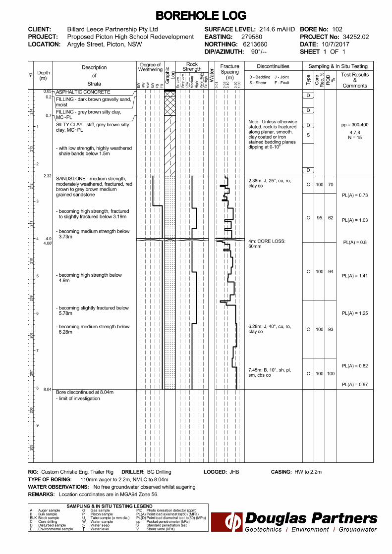
Note: Unless otherwisestated, rock is fracturedalong planar, smooth,clay coated or ironstained bedding planesdipping at 0-10°
2.38m: J, 25°, cu, ro,clay co
4m: CORE LOSS:60mm
6.28m: J, 40°, cu, ro,clay co
7.45m: B, 10°, sh, pl,sm, cbs co
pp = 300-400
4,7,8N = 15
PL(A) = 0.73
PL(A) = 1.03
PL(A) = 0.8
PL(A) = 1.41
PL(A) = 1.25
PL(A) = 0.82
PL(A) = 0.97
70
62
94
93
100
100
95
100
100
100
D
D
D
S
D
C
C
C
C
C
ASPHALTIC CONCRETE
FILLING - dark brown gravelly sand,moist
FILLING - grey brown silty clay,MC~PL
SILTY CLAY - stiff, grey brown siltyclay, MC~PL
- with low strength, highly weatheredshale bands below 1.5m
SANDSTONE - medium strength,moderately weathered, fractured, redbrown to grey brown mediumgrained sandstone
- becoming high strength, fracturedto slightly fractured below 3.19m
- becoming medium strength below3.73m
- becoming high strength below4.9m
- becoming slightly fractured below5.78m
- becoming medium strength below6.28m
Bore discontinued at 8.04m- limit of investigation
0.050.2
0.7
2.32
4.04.06
8.04
FractureSpacing
(m)
0.01
B - Bedding
S - Shear
RockStrength
Typ
e
Sampling & In Situ Testing
Ex
Low
Ver
y Lo
wLo
w
Med
ium
Hig
h
Ver
y H
igh
Ex
Hig
h
0.10
0.50
1.00 R
QD
%
Cor
eR
ec. %
Gra
phic
Log
Wat
er
Degree ofWeathering
EW
HW
MW
SW
FS
FR
Description
of
StrataJ - Joint
F - Fault
Test Results&
Comments0.05
Discontinuities
BOREHOLE LOG BOREHOLE LOG BOREHOLE LOG BOREHOLE LOG BOREHOLE LOG BOREHOLE LOG BOREHOLE LOG CLIENT:PROJECT:LOCATION: Argyle Street, Picton, NSW
SAMPLING & IN SITU TESTING LEGENDA Auger sample G Gas sample PID Photo ionisation detector (ppm)B Bulk sample P Piston sample PL(A) Point load axial test Is(50) (MPa)BLK Block sample Ux Tube sample (x mm dia.) PL(D) Point load diametral test Is(50) (MPa)C Core drilling W Water sample pp Pocket penetrometer (kPa)D Disturbed sample Water seep S Standard penetration testE Environmental sample Water level V Shear vane (kPa)
BORE No: 102PROJECT No: 34252.02DATE: 10/7/2017SHEET 1 OF 1
DRILLER: BG Drilling LOGGED: JHB CASING: HW to 2.2m
Billard Leece Partnership Pty LtdProposed Picton High School Redevelopment
REMARKS:
RIG: Custom Christie Eng. Trailer Rig
WATER OBSERVATIONS:
TYPE OF BORING:
No free groundwater observed whilst augering
110mm auger to 2.2m, NMLC to 8.04m
SURFACE LEVEL: 214.6 mAHDEASTING: 279580NORTHING: 6213660DIP/AZIMUTH: 90°/--
Location coordinates are in MGA94 Zone 56.
Depth(m) R
L
1
2
3
4
5
6
7
8
9
214
213
212
211
210
209
208
207
206
205

Note: Unless otherwisestated, rock is fracturedalong planar to curved,smooth, clay coatedbedding planes dippingat 0-15°
2.43m: J, 25°, sh, pl, ro,clay co
3.04m: Cs 10mm thick
4.45m: J, 28°, sh, pl,sm, cln
5.18m: B, 15°, sh, pl,sm, cln
6.36m: J, 6°, sh, pl, ro,cln
4,4,3N = 7
PL(A) = 3.95
PL(A) = 0.93
PL(A) = 0.94
PL(A) = 0.82
PL(A) = 1.42
PL(A) = 0.98
PL(A) = 0.52
72
83
97
90
82
100
100
100
100
100
D
D
D
S
CD
C
C
C
C
FILLING - brown silty clay (topsoil)
FILLING - appears poorlycompacted, grey brown silty claywith a trace of gravel, MC~PL
SANDSTONE - extremely low tovery low strength, brown and greymedium grained sandstone
SANDSTONE - medium strength,moderately weathered, fractured, redbrown to light grey medium grainedsandstone with very high strengthband- becoming fresh stained, slightly
fractured below 3.04m
- becoming high strength below6.29m
- becoming medium strength below6.85m
Bore discontinued at 8.07m- limit of investigation
0.1
2.0
2.2
8.07
FractureSpacing
(m)
0.01
B - Bedding
S - Shear
RockStrength
Typ
e
Sampling & In Situ Testing
Ex
Low
Ver
y Lo
wLo
w
Med
ium
Hig
h
Ver
y H
igh
Ex
Hig
h
0.10
0.50
1.00 R
QD
%
Cor
eR
ec. %
Gra
phic
Log
Wat
er
Degree ofWeathering
EW
HW
MW
SW
FS
FR
Description
of
StrataJ - Joint
F - Fault
Test Results&
Comments0.05
Discontinuities
BOREHOLE LOG BOREHOLE LOG BOREHOLE LOG BOREHOLE LOG BOREHOLE LOG BOREHOLE LOG BOREHOLE LOG CLIENT:PROJECT:LOCATION: Argyle Street, Picton, NSW
SAMPLING & IN SITU TESTING LEGENDA Auger sample G Gas sample PID Photo ionisation detector (ppm)B Bulk sample P Piston sample PL(A) Point load axial test Is(50) (MPa)BLK Block sample Ux Tube sample (x mm dia.) PL(D) Point load diametral test Is(50) (MPa)C Core drilling W Water sample pp Pocket penetrometer (kPa)D Disturbed sample Water seep S Standard penetration testE Environmental sample Water level V Shear vane (kPa)
BORE No: 103PROJECT No: 34252.02DATE: 11/7/2017SHEET 1 OF 1
DRILLER: BG Drilling LOGGED: JHB CASING: HW to 2.2m
Billard Leece Partnership Pty LtdProposed Picton High School Redevelopment
REMARKS:
RIG: Custom Christie Eng. Trailer Rig
WATER OBSERVATIONS:
TYPE OF BORING:
No free groundwater observed whilst augering
110mm auger to 2.2m, NMLC to 8.07m
SURFACE LEVEL: 215.6 mAHDEASTING: 279677NORTHING: 6213737DIP/AZIMUTH: 90°/--
Location coordinates are in MGA94 Zone 56.
Depth(m) R
L
1
2
3
4
5
6
7
8
9
215
214
213
212
211
210
209
208
207
206

Appendix C
Point Load Test Results
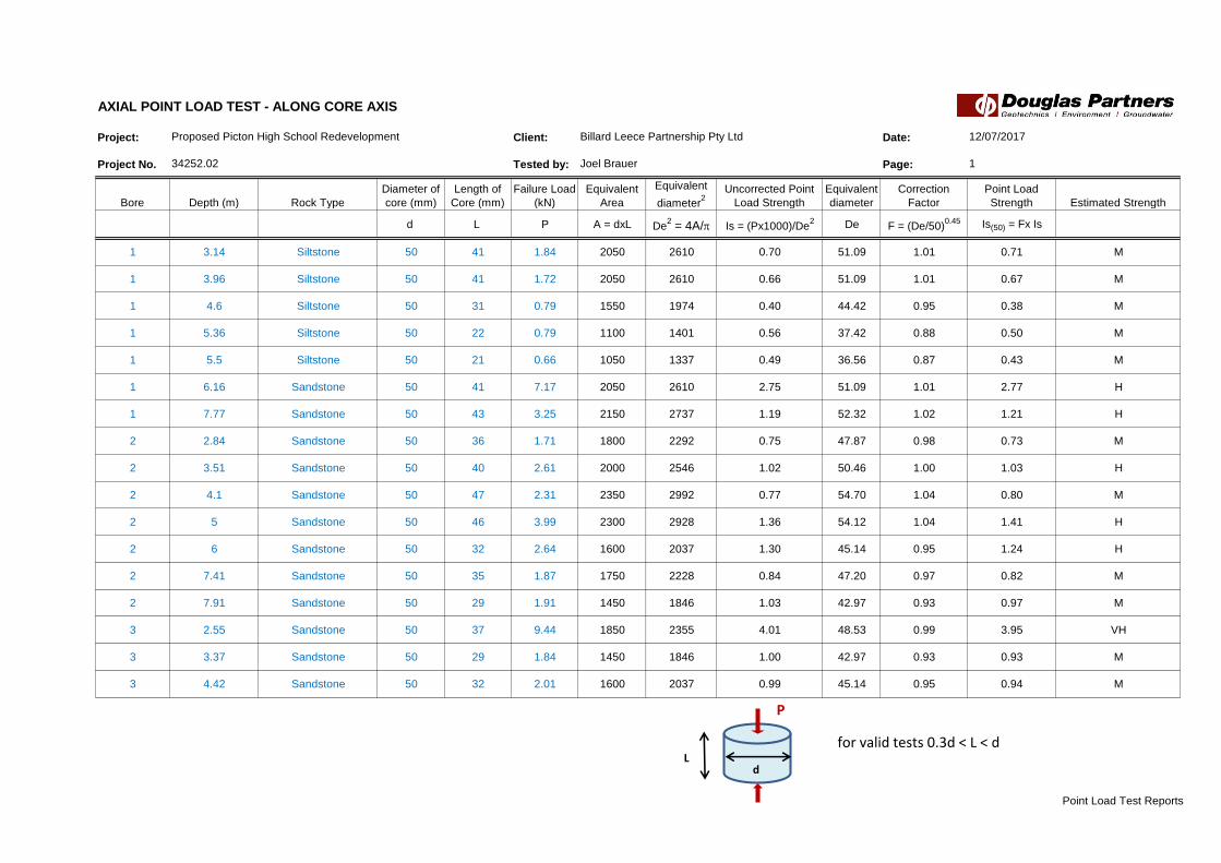
Project: Client: Date:
Project No. Tested by: Page:
Bore Depth (m) Rock Type
Diameter of
core (mm)
Length of
Core (mm)
Failure Load
(kN)
Equivalent
Area
Equivalent
diameter2
Uncorrected Point
Load Strength
Equivalent
diameter
Correction
Factor
Point Load
Strength Estimated Strength
d L P A = dxL De2 = 4A/p Is = (Px1000)/De
2 De F = (De/50)0.45 Is(50) = Fx Is
1 3.14 Siltstone 50 41 1.84 2050 2610 0.70 51.09 1.01 0.71 M
1 3.96 Siltstone 50 41 1.72 2050 2610 0.66 51.09 1.01 0.67 M
1 4.6 Siltstone 50 31 0.79 1550 1974 0.40 44.42 0.95 0.38 M
1 5.36 Siltstone 50 22 0.79 1100 1401 0.56 37.42 0.88 0.50 M
1 5.5 Siltstone 50 21 0.66 1050 1337 0.49 36.56 0.87 0.43 M
1 6.16 Sandstone 50 41 7.17 2050 2610 2.75 51.09 1.01 2.77 H
1 7.77 Sandstone 50 43 3.25 2150 2737 1.19 52.32 1.02 1.21 H
2 2.84 Sandstone 50 36 1.71 1800 2292 0.75 47.87 0.98 0.73 M
2 3.51 Sandstone 50 40 2.61 2000 2546 1.02 50.46 1.00 1.03 H
2 4.1 Sandstone 50 47 2.31 2350 2992 0.77 54.70 1.04 0.80 M
2 5 Sandstone 50 46 3.99 2300 2928 1.36 54.12 1.04 1.41 H
2 6 Sandstone 50 32 2.64 1600 2037 1.30 45.14 0.95 1.24 H
2 7.41 Sandstone 50 35 1.87 1750 2228 0.84 47.20 0.97 0.82 M
2 7.91 Sandstone 50 29 1.91 1450 1846 1.03 42.97 0.93 0.97 M
3 2.55 Sandstone 50 37 9.44 1850 2355 4.01 48.53 0.99 3.95 VH
3 3.37 Sandstone 50 29 1.84 1450 1846 1.00 42.97 0.93 0.93 M
3 4.42 Sandstone 50 32 2.01 1600 2037 0.99 45.14 0.95 0.94 M
12/07/2017
1
Proposed Picton High School Redevelopment
34252.02
AXIAL POINT LOAD TEST - ALONG CORE AXIS
Billard Leece Partnership Pty Ltd
Joel Brauer
d L
P
for valid tests 0.3d < L < d
Point Load Test Reports

Project: Client: Date:
Project No. Tested by: Page:
Bore Depth (m) Rock Type
Diameter of
core (mm)
Length of
Core (mm)
Failure Load
(kN)
Equivalent
Area
Equivalent
diameter2
Uncorrected Point
Load Strength
Equivalent
diameter
Correction
Factor
Point Load
Strength Estimated Strength
d L P A = dxL De2 = 4A/p Is = (Px1000)/De
2 De F = (De/50)0.45 Is(50) = Fx Is
3 5.51 Sandstone 50 25 1.44 1250 1592 0.90 39.89 0.90 0.82 M
3 6.43 Sandstone 50 36 3.32 1800 2292 1.45 47.87 0.98 1.42 H
3 7 Sandstone 50 49 2.91 2450 3119 0.93 55.85 1.05 0.98 M
3 8.03 Sandstone 50 44 1.41 2200 2801 0.50 52.93 1.03 0.52 M
AXIAL POINT LOAD TEST - ALONG CORE AXIS
Proposed Picton High School Redevelopment Billard Leece Partnership Pty Ltd 12/07/2017
34252.02 Joel Brauer 2
d L
P
for valid tests 0.3d < L < d
Point Load Test Reports

Appendix D
Aggressivity Test Results

CERTIFICATE OF ANALYSIS 171268
Client:
Douglas Partners Pty Ltd Smeaton Grange
18 Waler Crescent
Smeaton Grange
NSW 2567
Attention: Tom Mrdjen, Joel Brauer
Sample log in details:
Your Reference: 34252.02, Picton H.S
No. of samples: 3 soils
Date samples received / completed instructions received 13/07/17 / 13/07/17
Analysis Details:
Please refer to the following pages for results, methodology summary and quality control data.
Samples were analysed as received from the client. Results relate specifically to the samples as received.
Results are reported on a dry weight basis for solids and on an as received basis for other matrices.
Please refer to the last page of this report for any comments relating to the results.
Report Details:
Date results requested by: / Issue Date: 20/07/17 / 20/07/17
Date of Preliminary Report: Not Issued
NATA accreditation number 2901. This document shall not be reproduced except in full.
Accredited for compliance with ISO/IEC 17025 - Testing Tests not covered by NATA are denoted with *.
Results Approved By:
Page 1 of 6Envirolab Reference: 171268
Revision No: R 00

Client Reference: 34252.02, Picton H.S
Misc Inorg - Soil
Our Reference: UNITS 171268-1 171268-2 171268-3
Your Reference ------------
-
BH101: SPT 1.0 BH101: C 3.1-
3.4
BH102: SPT 1.0
Depth ------------ 1.0 3.1-3.4 1.0
Date Sampled
Type of sample
10/07/2017
Soil
10/07/2017
Soil
10/07/2017
Soil
Date prepared - 17/07/2017 17/07/2017 17/07/2017
Date analysed - 17/07/2017 17/07/2017 17/07/2017
pH 1:5 soil:water pH Units 5.9 9.0 5.3
Electrical Conductivity 1:5
soil:water
µS/cm 36 190 210
Chloride, Cl 1:5 soil:water mg/kg 10 37 210
Sulphate, SO4 1:5 soil:water mg/kg 21 <10 27
Page 2 of 6Envirolab Reference: 171268
Revision No: R 00

Client Reference: 34252.02, Picton H.S
Method ID Methodology Summary
Inorg-001 pH - Measured using pH meter and electrode in accordance with APHA latest edition, 4500-H+. Please note
that the results for water analyses are indicative only, as analysis outside of the APHA storage times.
Inorg-002 Conductivity and Salinity - measured using a conductivity cell at 25°C in accordance with APHA latest edition
2510 and Rayment & Lyons.
Inorg-081 Anions - a range of Anions are determined by Ion Chromatography, in accordance with APHA latest edition,
4110-B. Alternatively determined by colourimetry/turbidity using Discrete Analyer.
Page 3 of 6Envirolab Reference: 171268
Revision No: R 00

Client Reference: 34252.02, Picton H.S
QUALITY CONTROL UNITS PQL METHOD Blank Duplicate
Sm#
Duplicate results Spike Sm# Spike %
Recovery
Misc Inorg - Soil Base ll Duplicate ll %RPD
Date prepared - 17/07/2
017
171268-3 17/07/2017 || 17/07/2017 LCS-1 17/07/2017
Date analysed - 17/07/2
017
171268-3 17/07/2017 || 17/07/2017 LCS-1 17/07/2017
pH 1:5 soil:water pH Units Inorg-001 [NT] 171268-3 5.3 || 5.1 || RPD: 4 LCS-1 103%
Electrical Conductivity
1:5 soil:water
µS/cm 1 Inorg-002 <1 171268-3 210 || 220 || RPD: 5 LCS-1 101%
Chloride, Cl 1:5
soil:water
mg/kg 10 Inorg-081 <10 171268-3 210 || 200 || RPD: 5 LCS-1 99%
Sulphate, SO4 1:5
soil:water
mg/kg 10 Inorg-081 <10 171268-3 27 || 20 || RPD: 30 LCS-1 110%
Page 4 of 6Envirolab Reference: 171268
Revision No: R 00

Client Reference: 34252.02, Picton H.S
Report Comments:
Asbestos ID was analysed by Approved Identifier: Not applicable for this job
Asbestos ID was authorised by Approved Signatory: Not applicable for this job
INS: Insufficient sample for this test PQL: Practical Quantitation Limit NT: Not tested
NR: Test not required RPD: Relative Percent Difference NA: Test not required
<: Less than >: Greater than LCS: Laboratory Control Sample
Page 5 of 6Envirolab Reference: 171268
Revision No: R 00

Client Reference: 34252.02, Picton H.S
Quality Control Definitions
Blank: This is the component of the analytical signal which is not derived from the sample but from reagents,
glassware etc, can be determined by processing solvents and reagents in exactly the same manner as for samples.
Duplicate : This is the complete duplicate analysis of a sample from the process batch. If possible, the sample
selected should be one where the analyte concentration is easily measurable.
Matrix Spike : A portion of the sample is spiked with a known concentration of target analyte. The purpose of the matrix
spike is to monitor the performance of the analytical method used and to determine whether matrix interferences exist.
LCS (Laboratory Control Sample) : This comprises either a standard reference material or a control matrix (such as a blank
sand or water) fortified with analytes representative of the analyte class. It is simply a check sample.
Surrogate Spike: Surrogates are known additions to each sample, blank, matrix spike and LCS in a batch, of compounds
which are similar to the analyte of interest, however are not expected to be found in real samples.
Laboratory Acceptance Criteria
Duplicate sample and matrix spike recoveries may not be reported on smaller jobs, however, were analysed at a frequency
to meet or exceed NEPM requirements. All samples are tested in batches of 20. The duplicate sample RPD and matrix
spike recoveries for the batch were within the laboratory acceptance criteria.
Filters, swabs, wipes, tubes and badges will not have duplicate data as the whole sample is generally extracted
during sample extraction.
Spikes for Physical and Aggregate Tests are not applicable.
For VOCs in water samples, three vials are required for duplicate or spike analysis.
Duplicates: <5xPQL - any RPD is acceptable; >5xPQL - 0-50% RPD is acceptable.
Matrix Spikes, LCS and Surrogate recoveries: Generally 70-130% for inorganics/metals; 60-140%
for organics (+/-50% surrogates) and 10-140% for labile SVOCs (including labile surrogates), ultra trace organics
and speciated phenols is acceptable.
In circumstances where no duplicate and/or sample spike has been reported at 1 in 10 and/or 1 in 20 samples
respectively, the sample volume submitted was insufficient in order to satisfy laboratory QA/QC protocols.
When samples are received where certain analytes are outside of recommended technical holding times (THTs),
the analysis has proceeded. Where analytes are on the verge of breaching THTs, every effort will be made to analyse
within the THT or as soon as practicable.
Where sampling dates are not provided, Envirolab are not in a position to comment on the validity
of the analysis where recommended technical holding times may have been breached.
Measurement Uncertainty estimates are available for most tests upon request.
Page 6 of 6Envirolab Reference: 171268
Revision No: R 00

Appendix E
Preliminary Geotechnical Investigation Report (34252.02.R.001)

Report on Preliminary Geotechnical Investigation
Proposed Picton High School Redevelopment Argyle Street, Picton
Prepared for Billard Leece Partnership Pty Ltd
Project 34252.02 March 2017

Preliminary Geotechnical Investigation, Proposed Picton High School Redevelopment Project 76772.00.R.001.Rev0 Argyle Street, Picton March 2017
Table of Contents
Page
1. Introduction..................................................................................................................................... 1
2. Site Description .............................................................................................................................. 1
3. Regional Geology ........................................................................................................................... 2
4. Field Work Methods ....................................................................................................................... 2
5. Field Work Results ......................................................................................................................... 2
6. Laboratory Testing ......................................................................................................................... 3
7. Proposed Development .................................................................................................................. 4
8. Comments ...................................................................................................................................... 4
8.1 General ................................................................................................................................ 4
8.2 Subsurface Conditions ......................................................................................................... 5
8.3 Site Classification ................................................................................................................. 5
8.4 Earthworks ........................................................................................................................... 5
8.4.1 Site Preparation ...................................................................................................... 5
8.4.2 Excavation ............................................................................................................... 6
8.4.3 Reuse of Excavated Materials ................................................................................ 7
8.4.4 Batter Slopes ........................................................................................................... 7
8.5 Retaining Walls .................................................................................................................... 7
8.6 Footings ............................................................................................................................... 8
8.7 Subgrade Parameters .......................................................................................................... 8
9. Summary ........................................................................................................................................ 9
10. References ..................................................................................................................................... 9
11. Limitations ...................................................................................................................................... 9
Appendix A: About This Report
Drawing 1
Appendix B: Test Pit Logs (Pits 1 – 10)
Appendix C: Laboratory Test Results

Page 1 of 10
Preliminary Geotechnical Investigation, Proposed Picton High School Redevelopment Project 76772.00.R.001.Rev0 Argyle Street, Picton March 2017
Report on Preliminary Geotechnical Investigation
Proposed Picton High School Redevelopment
Argyle Street, Picton
1. Introduction
This report presents the results of a preliminary geotechnical investigation undertaken for proposed
redevelopment works within Picton High School at Argyle Street, Picton. The investigation was
commissioned in an email dated 12 January 2017 by Mr Shane Wood of Billard Leece Partnership Pty
Ltd (Architects) and was undertaken in accordance with Douglas Partners' (DP) proposal
MAC1600384 dated 21 November 2016.
DP understands that the proposed redevelopment works will include the removal of some
demountable buildings across the site and the construction of new teaching blocks, associated
facilities and pavements. The detailed design information of proposed new permanent buildings and
cut-fill plans are yet to be finalized.
The investigation included the excavation of test pits and laboratory testing of selected samples.
Details of the work undertaken and the results obtained are given within this report, together with
comments relating to design and construction practice.
The investigation discussed within was undertaken concurrently with a Contamination Assessment
(Project 34252.02.P.002) and Hazmat Survey (Project 34252.02.P.003), both of which will be reported
separately.
2. Site Description
Picton High School is located approximately 90 km to the south-west of the Sydney CBD and is a
rectangular shaped area of some 6 ha. Maximum north-south and east-west dimensions are
approximately 200 m and 290 m respectively. The school site is bounded by Argyle Street to the west,
residential properties to the north, and vacant land to the south and east. The school is currently
occupied by 32 existing buildings comprising permanent and demountable structures of various sizes,
a car park and playing fields.
The school site is located within undulating rises with overall topographic relief of approximately 8 m
from the highest parts (approximately RL218 m, relative to the Australian height datum) within the
eastern and western portions to the lowest part (approximately RL 210 m) within the mid northern
portion of the site. However, it has been partially levelled by cutting and filling to create flat platforms
for the existing structures.
Approximately, two-thirds of the site is covered by the existing structures and carparks. These
structures are generally located within the western portion of the site extending toward the middle
portion. Two sporting fields are noted along the eastern and southern boundaries of the school site. At

Page 2 of 10
Preliminary Geotechnical Investigation, Proposed Picton High School Redevelopment Project 76772.00.R.001.Rev0 Argyle Street, Picton March 2017
the time of the investigation, the vegetation across these open spaces was limited to well-maintained
light grass. Medium size trees were present along the northern boundary with scattered trees noted
between the existing buildings.
3. Regional Geology
Reference to the Wollongong-Port Hacking 1:100,000 Geological Sheet (Ref 1) indicates that the site
is underlain by Ashfield Shale (mapping unit Rwa) of the Wianamatta Group of Triassic age. The
Ashfield Shale typically comprises shale, siltstone, claystone and laminite with coal bands, all of which
weathered to form clays of high plasticity. The results of the investigation were consistent with the
geological mapping, with shale and siltstone of variable weathering with seams of fine grained lithic
sandstone encountered in the test pits.
4. Field Work Methods
The field work comprised the excavation of 10 test pits (Pits 1 – 10) to depths of 0.5 – 2.5 m with a
Takeuchi TB145 excavator fitted with a 300 mm bucket. The fieldwork was undertaken by a
geotechnical engineer who collected undisturbed samples (in 50mm thin walled tubes), disturbed
samples and bulk samples to assist in strata identification and for laboratory testing. Following
logging, testing and sampling, each test pits were backfilled and the ground surface reinstated to its
previous level.
The test pit locations were nominated by the client and located on site prior to the investigation using
differential GPS unit for which an accuracy of ± 20 mm is typical. The location of test pits are shown
on Drawing 1 (Appendix A). The surface levels were obtained using the differential GPS unit.
All field measurements and mapping for this project have been carried out using the Geodetic Datum
of Australia 1994 (GDA94) and the Map Grid of Australia 1994 (MGA94). All reduced levels are given
in relation to Australian Height Datum (AHD).
5. Field Work Results
The test pit logs are included in Appendix B, and should be read in conjunction with the accompanying
standard notes that define classification methods and descriptive terms. Relatively uniform conditions
were encountered underlying the site with the general succession of strata broadly summarised as
follows:
TOPSOIL – generally brown / grey silty clay (topsoil filling in Pits 1 – 4 & 7) with rootlets and
trace gravel to depths 0.1 – 0.3 m in all test pits with the exception of Pits 5 and 6;
FILLING – generally brown silty clay with some gravel to depths of 0.4 – 1.0 m in Pits 1 – 7;
CLAY – very stiff to hard red/brown silty clay with seams of extremely weathered shale in
Pits 1 – 5 & 8 to depths within the range 0.9 – 2.3 m; and

Page 3 of 10
Preliminary Geotechnical Investigation, Proposed Picton High School Redevelopment Project 76772.00.R.001.Rev0 Argyle Street, Picton March 2017
BEDROCK – extremely low strength to medium strength shale and sandstone generally at
depths within the range 0.9 m to 2.3 m in all test pits, other than Pits 9 and 10 where extremely
low strength shale was directly underlying the topsoil.
No free groundwater was observed in the test pits during excavation and for the short time that they
were left open. It is noted, however, that the test pits were immediately backfilled following logging
and sampling which precluded longer term monitoring of any groundwater levels that might be present.
It’s noted that groundwater levels are affected by factors such as weather conditions and can fluctuate
with time.
6. Laboratory Testing
Selected samples from the test pits were tested in the laboratory for measurement of field moisture
content, Atterberg limits, shrink-swell and California bearing ratio (CBR). The CBR tests were carried
out on samples compacted to approximately 100% dry density ratio relative to standard compaction at
standard optimum moisture content. The samples were then soaked for four days under surcharge
loadings of 4.5 kg. The detailed laboratory test report sheets are given in Appendix C, with the results
summarised in Table 1 – 3.
Table 1: Results of Atterberg Limits Testing
Pit
No.
Depth
(m)
WF
(%)
WL
(%)
WP
(%)
PI
(%)
LS
(%) Material
2 2.0 15.3 38 17 21 8.0 Clay
3 1.5 21.4 62 26 36 11.5 Clay
4 0.2 – 0.5 17.7 43 24 19 8.5 Filling
7 0.5 – 0.7 6.3 27 20 7 5.0 Filling
8 0.5 – 0.6 11.8 65 25 40 15.0 Gravelly clay
10 0.5 12.5 55 22 33 11.0 Shale
Where WF = Field moisture content WP = Plastic limit
WL = Liquid limit PI = Plasticity Index
LS = Linear shrinkage
The results indicate that the natural clays encountered on site appear to be of intermediate to high
plasticity and as such, would be expected to be susceptible to shrinkage and swelling movements due
to seasonal moisture variations.
Table 2: Results of Shrink Swell Testing
Pit No. Depth
(m)
WF
(%)
Iss
(%/pF) Material
6 0.5 – 0.9 8.3 0.3 Filling
8 0.3 – 0.7 19.9 0.4 Gravelly clay
Where WF = Field moisture content Iss = Shrink-Swell Index

Page 4 of 10
Preliminary Geotechnical Investigation, Proposed Picton High School Redevelopment Project 76772.00.R.001.Rev0 Argyle Street, Picton March 2017
The shrink-swell index (Iss) test results indicate the gravelly clays are of low shrink-swell potential due
to changes in soil moisture content. However, considering the results of Atterberg limits and linear
shrinkage tests on the fine grained portions (passing 0.075 mm) of same material, a moderate shrink-
swell potential is suggested for silty clays underlying the site.
Table 3: Results of California Bearing Ratio Testing
Pit
No
Depth
(m)
FMC
(%)
OMC
(%)
MDD
(t/m3)
Swell
(%)
CBR
(%) Material
1 0.5 – 0.7 17.6 22.8 1.49 0.7 4 Filling
2 0.5 – 0.7 18.5 25.5 1.55 0.2 3.5 Filling
3 0.5 – 0.7 15.0 21.2 1.60 0.2 6 Gravelly clay
7 0.3 – 0.5 9.3 14.0 1.85 0.7 3.5 Filling
9 0.5 – 0.7 9.8 15.2 1.77 1.1 6 Shale
Where FMC = Field moisture content OMC = Optimum moisture content
MDD = Maximum dry density CBR = California bearing ratio
The results of the field moisture content tests (at the time of the sampling) listed in Table 3 indicate the
soils ranged between approximately 4.7 – 7% dry of standard optimum moisture content.
7. Proposed Development
It is understood that the redevelopment works comprising the removal of selected demountable
buildings within the site and the construction of new permanent teaching blocks are proposed. Some
of the demountable buildings are proposed to be relocated as a part of this project. The proposed
permanent buildings are likely to be one or two storey relatively lightweight structures and are
expected to be founded on pads/shallow piers constructed within suitable natural material or controlled
filing. However, the quantity, locations, design loads and other design information of the structures are
unknown at this time. As parts of the redevelopment works, the construction of access roads and
installation of services will also be required.
8. Comments
8.1 General
The following comments are based on the surface and subsurface profiles encountered in the test pits.
Comments are provided in the following sections on development constraints related to geotechnical
and geological factors to assist in the foundation design of the proposed new buildings. As detailed
design of the proposed redevelopment works has not been undertaken, the comments given must also
be considered as being preliminary in nature. Once details are available, they should be forwarded to
DP for review to determine if comments given within this report are appropriate or require revision.

Page 5 of 10
Preliminary Geotechnical Investigation, Proposed Picton High School Redevelopment Project 76772.00.R.001.Rev0 Argyle Street, Picton March 2017
8.2 Subsurface Conditions
The investigation findings have indicated that near-surface conditions underlying the site generally
comprise topsoil and filling to depths 0.3 – 1.0 m, overlying silty clay and stiff to hard gravelly clay in all
test pits except for Pits 9 and 10 where topsoil was directly underlain by extremely weathered shale.
Bedrock comprising weathered shale and lithic sandstone were found in all other test pits on first
contact at depths of 0.9 – 1.8 m and continued to the auger refusal depths within the range 0.5 –
2.5 m.
8.3 Site Classification
It is inferred that fill material found throughout the site was not placed in accordance with recognised
standards and would be considered ‘uncontrolled’ in accordance with the requirements of
AS3798 (Ref 2), unless documents indicating the fill material has been placed in a controlled manner
supplied by the client.
Based on the subsurface conditions encountered during the investigation, due to presence of
uncontrolled filling deeper than 0.4 m, the site would be classified as Class P in accordance with
AS 2870 (Ref 3). The natural soils underlying the site would be equivalent to Class M as described in
AS 2870 (Ref 3).
8.4 Earthworks
8.4.1 Site Preparation
It is recommended that all filling be placed and compacted in accordance with Level 1 requirements
(AS3798 – 2007). To prepare the site for the construction of new buildings, the following procedures
are suggested.
Stripping of vegetation and organic topsoils (to expected maximum depths of 0.3 m) and
separately stockpiled for use in landscaping or removed off site;
Stripping of uncontrolled fill and unsuitable material within the footprint of the proposed buildings.
Inspection of the stripped surface by a geotechnical engineer;
Compaction of the exposed surface with at least of 8 passes of a 12 tonne (minimum dead
weight) roller, followed by test rolling in the presence of a geotechnical engineer. Where soft
spots are identified, they should be excavated and then backfilled using a suitable granular
material. Additional filling may also be required to elevate building platforms. All filling should be
placed in 250 mm (loose thickness) layers and compacted with placement moisture contents
within the range of -2% to +2% of OMC in order to limit surface deflection during proof rolling.
Surface drainage should be maintained at all times by adopting appropriate cross-falls across the
site. Surface drainage should be installed as soon as is practicable in order to capture and
remove surface flows to prevent erosion and softening of the exposed surface.
Filling delivered to site must be approved by the geotechnical consultant prior to delivery to site.
Highly reactive clay filling should be avoided.

Page 6 of 10
Preliminary Geotechnical Investigation, Proposed Picton High School Redevelopment Project 76772.00.R.001.Rev0 Argyle Street, Picton March 2017
Site observations and laboratory test results have indicated the presence of high plasticity silty clays in
some areas which could be adversely affected by inclement weather. Whilst these soils are typically
of a stiff to very stiff consistency when dry, they can rapidly lose strength during rainfall and
subsequent partial saturation and result in difficult trafficability conditions.
Conventional sediment and erosion control measures should be implemented during the construction
phase, with exposed surfaces to be topsoiled and vegetated as soon as practicable following the
completion of earthworks.
8.4.2 Excavation
All topsoil, filling, natural soils and bedrock up to very low to low strength should be readily removed
using a conventional medium sized excavator with a toothed bucket.
The final earthworks plans have not been finalized at the time of preparing this report. The excavation
are expected to be limited to the removal of moisture affected material within the footprint of
demolished buildings and replacing by suitable filling and drilling for piers or footing of new structures
and installation of services. Bucket refusal on weathered rock was encountered in all test pits. Where
low to medium strength rock was encountered, these areas will, for the most part, be adequately
removed during bulk earthworks using a large excavator with some light to medium ripping. However,
larger plant may provide greater excavation efficiency particularly during drilling of pier foundations.
Medium to high strength rock was not encountered in the test pits. If encountered during detailed
excavation for services or foundations, these areas will offer greater resistance to light ripping and are
likely to require pneumatic/hydraulic hammering equipment in combination with rock sawing and/or
grinding to achieve the required cut depths for this project.
Due to the proximity of surrounding buildings and presence of filling at shallow depth, the vibration
resulting from the excavation could cause damage to the underground services or demountable and
brick structures. It is recommended, if the use of percussive equipment is required within 40 m of any
vibration sensitive structures, vibration monitoring should be undertaken. If the monitoring indicates
unacceptable levels of vibration, then the use of non-percussive (ie: rock sawing and ripping)
excavation methods will be required. This requirement however, will need to be determined on site
once the details of the bulk earthworks and proposed excavation equipment are known.
Anticipated equipments required for excavations are given as a guide only. Additional drilling
investigation within the footprint of proposed structures is recommended to more accurately define the
interface of filling, natural soil and provide quantitative information on the rock material properties
where deep excavation within the rock profiles are expected. Where rock is encountered at design
finished surface level, it is recommended that a minimum of 300 mm of topsoil be placed over the
surface in order to better promote revegetation of the surface.
For information on soil and rock types and indicative strength, reference must be made to the
individual logs which are included in Appendix B. Tenderers must make their own assessment of
excavation condition with the information given on the test pit logs provided as preliminary information
only.

Page 7 of 10
Preliminary Geotechnical Investigation, Proposed Picton High School Redevelopment Project 76772.00.R.001.Rev0 Argyle Street, Picton March 2017
8.4.3 Reuse of Excavated Materials
Generally, the filling, natural clays and bedrock of up to low strength encountered during the
investigation, will be suitable for reuse as engineered filling within the site. The material should not
contain any particle sizes greater than 150 mm as these may cause inadequate compaction, and
should not contain silts due to their propensity for saturation and erosion. Topsoil and other
deleterious materials will not be suitable as a fill material but could be stockpiled for potential use in
landscaping or alternatively, removal from site.
8.4.4 Batter Slopes
While cut slopes within the clays may often stand vertically and unsupported (provided no nearby
structures are present) for short periods of time, they will rapidly lose strength upon exposure to
weather. A maximum batter slope of 1(H):1(V) is recommended for unsurcharged temporary slopes in
stiff clays. The maximum batter slope should be reduced to 3(H):1(V) for temporary batters in
uncontrolled filling.
Where the slopes are to be vegetated to prevent erosion, a maximum final batter slope of 3(H):1(V) is
recommended. If batters greater than 4 m in height are required, the inclusion of an intermediate
bench every 5 m in height, approximately 3 m wide, is recommended to reduce the effects of scour
and erosion.
Where filling batters are formed, similar parameters to those recommended for cut slopes can be
adopted. However, it is recommended that whilst the slope is being formed the batters should be
over-filled in near-horizontal lifts and cut back to form the design grades.
8.5 Retaining Walls
Where engineer-designed retaining walls are proposed, the following measures should be
incorporated into the design:
Backfilling of the void between the wall and the slope using imported, free draining granular
material connected into a drainage pipe at the base of the wall;
Capping of the backfill (where exposed) with compacted clay or concrete to prevent surface runoff
entering the backfill;
Provision of an open drain to collect and divert surface runoff from ponding above the wall;
For horizontal backfill or retained soils, design based on an average bulk unit weight for retained
material of 20 kN/m3 and on a triangular earth pressure distribution based on an active earth
pressure coefficient of (Ka) 0.3 for compacted filling and natural clay where no movement
sensitive structures are located within a horizontal distance of 2H (where H is the vertical height
of the retained zone) of the rear of the wall;
Where there are movement sensitive structures located within the abovementioned critical zone,
an at rest pressure coefficient (K0) of 0.6 should be adopted;
If hydrostatic pressures are allowed, soil densities could be reduced to the buoyant values.

Page 8 of 10
Preliminary Geotechnical Investigation, Proposed Picton High School Redevelopment Project 76772.00.R.001.Rev0 Argyle Street, Picton March 2017
If an adequate drainage medium is not provided behind the retaining wall, then hydrostatic pressures
must be incorporated within the design with soil parameters reduced to their buoyant values.
8.6 Footings
The proposed redevelopment is expected to comprise one and two storey buildings. It is anticipated
that the buildings will be of relatively light weight constrcution.
Design of footings for the structures can only be undertaken once the final design loads and finished
levels have been determined. As a guide however and based on the results of the subsurface
investigation and the range of soils encountered, preliminary footing design could be based on the
parameters presented in Table 4.
Table 4: Preliminary Footing Design Parameters
Material Allowable Base Bearing Pressures
(kPa)
Stiff clay or controlled filling 150
Very stiff clays or stronger 200
Weathered rock 500
8.7 Subgrade Parameters
The results of laboratory testing on the samples tested are included in Table 3. The laboratory testing
gave CBR values within the range 3.5% – 4% for filling and CBR values of 4% and 6% for gravelly
clay and extremely weathered shale respectively.
To allow for natural variations in subsurface conditions, it is suggested that a design CBR value of
3.5% be adopted as a basis of pavement design.
Drainage measures should be adopted to ensure that the subgrade and pavements do not become
saturated in service. The exposed subgrade should be closely inspected at the time of construction to
ensure that material of lower than the assumed design strength does not support the pavement at any
locations. Should weaker subgrade material be encountered, consideration should be given to
removing and replacing the weak strata with a higher material, or reassessing the pavement design.
Effective erosion and sedimentation control measures should be installed maintained for the duration
of the construction. Furthermore, adequate drainage of all working areas shall be maintained
throughout the period of construction to ensure run-off of water without ponding except where ponding
forms part of a planned erosion and sedimentation control system.
To promote long term performance of the pavements, sub soil drainage and related features should
also be considered to minimise moisture ingress and subsequent pavement failure.

Page 9 of 10
Preliminary Geotechnical Investigation, Proposed Picton High School Redevelopment Project 76772.00.R.001.Rev0 Argyle Street, Picton March 2017
9. Summary
The investigation included the excavation of test pits within the proposed school site at the nominated
locations by the client. The collected undisturbed and bulk soil samples were returned to out NATA
accredited laboratory for measurement of field moisture content, plasticity, shrink swell Index and CBR
value of subsurface material.
The test pits have indicated that subsurface conditions underlying the site generally comprise variable
depths of filling and topsoil overlying silty clay and clay of very stiff to hard consistency. Rock was
encountered in all test pits on first contact at depths of between within the range 0.3 m to 2.3 m.
The site preparation and earthworks are to be undertaken in accordance with Section 8.4. The site has
been classified Class P due to presence of uncontrolled filling deeper than 0.4 m and existing
structures. The preliminary bearing capacity parameters for the design of footings are given in
Table 4.
The results of CBR testing indicate the CBR values within the range 3.5 – 6% for near-surface material
underlying the site. It is suggested that a design CBR value of 3.5% be adopted as a basis of
pavement design.
Consideration must be given to the preliminary nature of the investigation and potential for variability in
the subsurface condition across the site. Once design is suitably advanced, DP must review the plans
to determine if the comments given within are appropriate or if additional investigations are required.
10. References
1. Geology of 1:100 000 Wollongong – Port Hacking Geological Series Sheet No 9029 – 9129,
Dept of Mines, (1985).
2. Australian Standard AS 3798 – 2007 Guidelines on Earthworks for Commercial and Residential
Developments.
3. Australian Standard AS 2870 – 2011 Residential Footings and Slabs.
4. AUSTROADS, "Guide to Pavement Technology – Part 2: Pavement Structural Design", 2012.
11. Limitations
Douglas Partners (DP) has prepared this report (or services) for the proposed redevelopment works at
Picton High School in accordance with DP’s proposal dated 21 November 2016 and acceptance
received from Mr Shane Wood dated 12 January 2017. The work was carried out under projects
General Terms and Conditions. This report is provided for the exclusive use of Billard Leece
Partnership Pty Ltd for this project only and for the purposes as described in the report. It should not
be used for other projects or by a third party. Any party so relying upon this report beyond its
exclusive use and purpose as stated above, and without the express written consent of DP, does so
entirely at its own risk and without recourse to DP for any loss or damage. In preparing this report DP
has necessarily relied upon information provided by the client and/or their agents.

Page 10 of 10
Preliminary Geotechnical Investigation, Proposed Picton High School Redevelopment Project 76772.00.R.001.Rev0 Argyle Street, Picton March 2017
The results provided in the report are indicative of the sub-surface conditions on the site only at the
specific sampling and/or testing locations, and then only to the depths investigated and at the time the
work was carried out. Sub-surface conditions can change abruptly due to variable geological
processes and also as a result of human influences. Such changes may occur after DP’s field testing
has been completed.
DP’s advice is based upon the conditions encountered during this investigation. The accuracy of the
advice provided by DP in this report may be affected by undetected variations in ground conditions
across the site between and beyond the sampling and/or testing locations. The advice may also be
limited by budget constraints imposed by others or by site accessibility.
This report must be read in conjunction with all of the attached and should be kept in its entirety
without separation of individual pages or sections. DP cannot be held responsible for interpretations
or conclusions made by others unless they are supported by an expressed statement, interpretation,
outcome or conclusion stated in this report.
This report, or sections from this report, should not be used as part of a specification for a project,
without review and agreement by DP. This is because this report has been written as advice and
opinion rather than instructions for construction.
Douglas Partners Pty Ltd

Appendix A
About This Report Drawing 1

July 2010
Introduction These notes have been provided to amplify DP's report in regard to classification methods, field procedures and the comments section. Not all are necessarily relevant to all reports. DP's reports are based on information gained from limited subsurface excavations and sampling, supplemented by knowledge of local geology and experience. For this reason, they must be regarded as interpretive rather than factual documents, limited to some extent by the scope of information on which they rely. Copyright This report is the property of Douglas Partners Pty Ltd. The report may only be used for the purpose for which it was commissioned and in accordance with the Conditions of Engagement for the commission supplied at the time of proposal. Unauthorised use of this report in any form whatsoever is prohibited. Borehole and Test Pit Logs The borehole and test pit logs presented in this report are an engineering and/or geological interpretation of the subsurface conditions, and their reliability will depend to some extent on frequency of sampling and the method of drilling or excavation. Ideally, continuous undisturbed sampling or core drilling will provide the most reliable assessment, but this is not always practicable or possible to justify on economic grounds. In any case the boreholes and test pits represent only a very small sample of the total subsurface profile. Interpretation of the information and its application to design and construction should therefore take into account the spacing of boreholes or pits, the frequency of sampling, and the possibility of other than 'straight line' variations between the test locations. Groundwater Where groundwater levels are measured in boreholes there are several potential problems, namely: • In low permeability soils groundwater may
enter the hole very slowly or perhaps not at all during the time the hole is left open;
• A localised, perched water table may lead to an erroneous indication of the true water table;
• Water table levels will vary from time to time with seasons or recent weather changes. They may not be the same at the time of construction as are indicated in the report; and
• The use of water or mud as a drilling fluid will mask any groundwater inflow. Water has to be blown out of the hole and drilling mud must first be washed out of the hole if water measurements are to be made.
More reliable measurements can be made by installing standpipes which are read at intervals over several days, or perhaps weeks for low permeability soils. Piezometers, sealed in a particular stratum, may be advisable in low permeability soils or where there may be interference from a perched water table. Reports The report has been prepared by qualified personnel, is based on the information obtained from field and laboratory testing, and has been undertaken to current engineering standards of interpretation and analysis. Where the report has been prepared for a specific design proposal, the information and interpretation may not be relevant if the design proposal is changed. If this happens, DP will be pleased to review the report and the sufficiency of the investigation work. Every care is taken with the report as it relates to interpretation of subsurface conditions, discussion of geotechnical and environmental aspects, and recommendations or suggestions for design and construction. However, DP cannot always anticipate or assume responsibility for: • Unexpected variations in ground conditions.
The potential for this will depend partly on borehole or pit spacing and sampling frequency;
• Changes in policy or interpretations of policy by statutory authorities; or
• The actions of contractors responding to commercial pressures.
If these occur, DP will be pleased to assist with investigations or advice to resolve the matter.

July 2010
Site Anomalies In the event that conditions encountered on site during construction appear to vary from those which were expected from the information contained in the report, DP requests that it be immediately notified. Most problems are much more readily resolved when conditions are exposed rather than at some later stage, well after the event. Information for Contractual Purposes Where information obtained from this report is provided for tendering purposes, it is recommended that all information, including the written report and discussion, be made available. In circumstances where the discussion or comments section is not relevant to the contractual situation, it may be appropriate to prepare a specially edited document. DP would be pleased to assist in this regard and/or to make additional report copies available for contract purposes at a nominal charge. Site Inspection The company will always be pleased to provide engineering inspection services for geotechnical and environmental aspects of work to which this report is related. This could range from a site visit to confirm that conditions exposed are as expected, to full time engineering presence on site.

July 2010
Introduction The Cone Penetration Test (CPT) is a sophisticated soil profiling test carried out in-situ. A special cone shaped probe is used which is connected to a digital data acquisition system. The cone and adjoining sleeve section contain a series of strain gauges and other transducers which continuously monitor and record various soil parameters as the cone penetrates the soils. The soil parameters measured depend on the type of cone being used, however they always include the following basic measurements • Cone tip resistance qc • Sleeve friction fs • Inclination (from vertical) i • Depth below ground z Figure 1: Cone Diagram The inclinometer in the cone enables the verticality of the test to be confirmed and, if required, the vertical depth can be corrected. The cone is thrust into the ground at a steady rate of about 20 mm/sec, usually using the hydraulic rams of a purpose built CPT rig, or a drilling rig. The testing is carried out in accordance with the Australian Standard AS1289 Test 6.5.1.
Figure 2: Purpose built CPT rig The CPT can penetrate most soil types and is particularly suited to alluvial soils, being able to detect fine layering and strength variations. With sufficient thrust the cone can often penetrate a short distance into weathered rock. The cone will usually reach refusal in coarse filling, medium to coarse gravel and on very low strength or better rock. Tests have been successfully completed to more than 60 m. Types of CPTs Douglas Partners (and its subsidiary GroundTest) owns and operates the following types of CPT cones:
Type Measures Standard Basic parameters (qc, fs, i & z) Piezocone Dynamic pore pressure (u) plus
basic parameters. Dissipation tests estimate consolidation parameters
Conductivity Bulk soil electrical conductivity (σ) plus basic parameters
Seismic Shear wave velocity (Vs), compression wave velocity (Vp), plus basic parameters
Strata Interpretation The CPT parameters can be used to infer the Soil Behaviour Type (SBT), based on normalised values of cone resistance (Qt) and friction ratio (Fr). These are used in conjunction with soil classification charts, such as the one below (after Robertson 1990)

July 2010
Figure 3: Soil Classification Chart DP's in-house CPT software provides computer aided interpretation of soil strata, generating soil descriptions and strengths for each layer. The software can also produce plots of estimated soil parameters, including modulus, friction angle, relative density, shear strength and over consolidation ratio. DP's CPT software helps our engineers quickly evaluate the critical soil layers and then focus on developing practical solutions for the client's project. Engineering Applications There are many uses for CPT data. The main applications are briefly introduced below: Settlement CPT provides a continuous profile of soil type and strength, providing an excellent basis for settlement analysis. Soil compressibility can be estimated from cone derived moduli, or known consolidation parameters for the critical layers (eg. from laboratory testing). Further, if pore pressure dissipation tests are undertaken using a piezocone, in-situ consolidation coefficients can be estimated to aid analysis.
Pile Capacity The cone is, in effect, a small scale pile and, therefore, ideal for direct estimation of pile capacity. DP's in-house program ConePile can analyse most pile types and produces pile capacity versus depth plots. The analysis methods are based on proven static theory and empirical studies, taking account of scale effects, pile materials and method of installation. The results are expressed in limit state format, consistent with the Piling Code AS2159. Dynamic or Earthquake Analysis CPT and, in particular, Seismic CPT are suitable for dynamic foundation studies and earthquake response analyses, by profiling the low strain shear modulus G0. Techniques have also been developed relating CPT results to the risk of soil liquefaction. Other Applications Other applications of CPT include ground improvement monitoring (testing before and after works), salinity and contaminant plume mapping (conductivity cone), preloading studies and verification of strength gain. Figure 4: Sample Cone Plot

July 2010
Rock Strength Rock strength is defined by the Point Load Strength Index (Is(50)) and refers to the strength of the rock substance and not the strength of the overall rock mass, which may be considerably weaker due to defects. The test procedure is described by Australian Standard 4133.4.1 - 1993. The terms used to describe rock strength are as follows:
Term Abbreviation Point Load Index Is(50) MPa
Approx Unconfined Compressive Strength MPa*
Extremely low EL <0.03 <0.6
Very low VL 0.03 - 0.1 0.6 - 2
Low L 0.1 - 0.3 2 - 6
Medium M 0.3 - 1.0 6 - 20
High H 1 - 3 20 - 60
Very high VH 3 - 10 60 - 200
Extremely high EH >10 >200 * Assumes a ratio of 20:1 for UCS to Is(50)
Degree of Weathering The degree of weathering of rock is classified as follows:
Term Abbreviation Description Extremely weathered EW Rock substance has soil properties, i.e. it can be remoulded
and classified as a soil but the texture of the original rock is still evident.
Highly weathered HW Limonite staining or bleaching affects whole of rock substance and other signs of decomposition are evident. Porosity and strength may be altered as a result of iron leaching or deposition. Colour and strength of original fresh rock is not recognisable
Moderately weathered
MW Staining and discolouration of rock substance has taken place
Slightly weathered SW Rock substance is slightly discoloured but shows little or no change of strength from fresh rock
Fresh stained Fs Rock substance unaffected by weathering but staining visible along defects
Fresh Fr No signs of decomposition or staining Degree of Fracturing The following classification applies to the spacing of natural fractures in diamond drill cores. It includes bedding plane partings, joints and other defects, but excludes drilling breaks.
Term Description Fragmented Fragments of <20 mm Highly Fractured Core lengths of 20-40 mm with some fragments Fractured Core lengths of 40-200 mm with some shorter and longer sections Slightly Fractured Core lengths of 200-1000 mm with some shorter and loner sections Unbroken Core lengths mostly > 1000 mm

July 2010
Rock Quality Designation The quality of the cored rock can be measured using the Rock Quality Designation (RQD) index, defined as:
RQD % = cumulative length of 'sound' core sections ≥ 100 mm long total drilled length of section being assessed
where 'sound' rock is assessed to be rock of low strength or better. The RQD applies only to natural fractures. If the core is broken by drilling or handling (i.e. drilling breaks) then the broken pieces are fitted back together and are not included in the calculation of RQD. Stratification Spacing For sedimentary rocks the following terms may be used to describe the spacing of bedding partings:
Term Separation of Stratification Planes Thinly laminated < 6 mm Laminated 6 mm to 20 mm Very thinly bedded 20 mm to 60 mm Thinly bedded 60 mm to 0.2 m Medium bedded 0.2 m to 0.6 m Thickly bedded 0.6 m to 2 m Very thickly bedded > 2 m

July 2010
Sampling Sampling is carried out during drilling or test pitting to allow engineering examination (and laboratory testing where required) of the soil or rock. Disturbed samples taken during drilling provide information on colour, type, inclusions and, depending upon the degree of disturbance, some information on strength and structure. Undisturbed samples are taken by pushing a thin-walled sample tube into the soil and withdrawing it to obtain a sample of the soil in a relatively undisturbed state. Such samples yield information on structure and strength, and are necessary for laboratory determination of shear strength and compressibility. Undisturbed sampling is generally effective only in cohesive soils. Test Pits Test pits are usually excavated with a backhoe or an excavator, allowing close examination of the in-situ soil if it is safe to enter into the pit. The depth of excavation is limited to about 3 m for a backhoe and up to 6 m for a large excavator. A potential disadvantage of this investigation method is the larger area of disturbance to the site. Large Diameter Augers Boreholes can be drilled using a rotating plate or short spiral auger, generally 300 mm or larger in diameter commonly mounted on a standard piling rig. The cuttings are returned to the surface at intervals (generally not more than 0.5 m) and are disturbed but usually unchanged in moisture content. Identification of soil strata is generally much more reliable than with continuous spiral flight augers, and is usually supplemented by occasional undisturbed tube samples. Continuous Spiral Flight Augers The borehole is advanced using 90-115 mm diameter continuous spiral flight augers which are withdrawn at intervals to allow sampling or in-situ testing. This is a relatively economical means of drilling in clays and sands above the water table. Samples are returned to the surface, or may be collected after withdrawal of the auger flights, but they are disturbed and may be mixed with soils from the sides of the hole. Information from the drilling (as distinct from specific sampling by SPTs or undisturbed samples) is of relatively low
reliability, due to the remoulding, possible mixing or softening of samples by groundwater. Non-core Rotary Drilling The borehole is advanced using a rotary bit, with water or drilling mud being pumped down the drill rods and returned up the annulus, carrying the drill cuttings. Only major changes in stratification can be determined from the cuttings, together with some information from the rate of penetration. Where drilling mud is used this can mask the cuttings and reliable identification is only possible from separate sampling such as SPTs. Continuous Core Drilling A continuous core sample can be obtained using a diamond tipped core barrel, usually with a 50 mm internal diameter. Provided full core recovery is achieved (which is not always possible in weak rocks and granular soils), this technique provides a very reliable method of investigation. Standard Penetration Tests Standard penetration tests (SPT) are used as a means of estimating the density or strength of soils and also of obtaining a relatively undisturbed sample. The test procedure is described in Australian Standard 1289, Methods of Testing Soils for Engineering Purposes - Test 6.3.1. The test is carried out in a borehole by driving a 50 mm diameter split sample tube under the impact of a 63 kg hammer with a free fall of 760 mm. It is normal for the tube to be driven in three successive 150 mm increments and the 'N' value is taken as the number of blows for the last 300 mm. In dense sands, very hard clays or weak rock, the full 450 mm penetration may not be practicable and the test is discontinued. The test results are reported in the following form. • In the case where full penetration is obtained
with successive blow counts for each 150 mm of, say, 4, 6 and 7 as:
4,6,7 N=13
• In the case where the test is discontinued before the full penetration depth, say after 15 blows for the first 150 mm and 30 blows for the next 40 mm as:
15, 30/40 mm

July 2010
The results of the SPT tests can be related empirically to the engineering properties of the soils. Dynamic Cone Penetrometer Tests / Perth Sand Penetrometer Tests Dynamic penetrometer tests (DCP or PSP) are carried out by driving a steel rod into the ground using a standard weight of hammer falling a specified distance. As the rod penetrates the soil the number of blows required to penetrate each successive 150 mm depth are recorded. Normally there is a depth limitation of 1.2 m, but this may be extended in certain conditions by the use of extension rods. Two types of penetrometer are commonly used. • Perth sand penetrometer - a 16 mm diameter
flat ended rod is driven using a 9 kg hammer dropping 600 mm (AS 1289, Test 6.3.3). This test was developed for testing the density of sands and is mainly used in granular soils and filling.
• Cone penetrometer - a 16 mm diameter rod with a 20 mm diameter cone end is driven using a 9 kg hammer dropping 510 mm (AS 1289, Test 6.3.2). This test was developed initially for pavement subgrade investigations, and correlations of the test results with California Bearing Ratio have been published by various road authorities.

July 2010
Description and Classification Methods The methods of description and classification of soils and rocks used in this report are based on Australian Standard AS 1726, Geotechnical Site Investigations Code. In general, the descriptions include strength or density, colour, structure, soil or rock type and inclusions. Soil Types Soil types are described according to the predominant particle size, qualified by the grading of other particles present:
Type Particle size (mm) Boulder >200 Cobble 63 - 200 Gravel 2.36 - 63 Sand 0.075 - 2.36 Silt 0.002 - 0.075 Clay <0.002
The sand and gravel sizes can be further subdivided as follows:
Type Particle size (mm) Coarse gravel 20 - 63 Medium gravel 6 - 20 Fine gravel 2.36 - 6 Coarse sand 0.6 - 2.36 Medium sand 0.2 - 0.6 Fine sand 0.075 - 0.2
The proportions of secondary constituents of soils are described as:
Term Proportion Example And Specify Clay (60%) and
Sand (40%) Adjective 20 - 35% Sandy Clay Slightly 12 - 20% Slightly Sandy
Clay With some 5 - 12% Clay with some
sand With a trace of 0 - 5% Clay with a trace
of sand
Definitions of grading terms used are: • Well graded - a good representation of all
particle sizes • Poorly graded - an excess or deficiency of
particular sizes within the specified range • Uniformly graded - an excess of a particular
particle size • Gap graded - a deficiency of a particular
particle size with the range Cohesive Soils Cohesive soils, such as clays, are classified on the basis of undrained shear strength. The strength may be measured by laboratory testing, or estimated by field tests or engineering examination. The strength terms are defined as follows:
Description Abbreviation Undrained shear strength
(kPa) Very soft vs <12 Soft s 12 - 25 Firm f 25 - 50 Stiff st 50 - 100 Very stiff vst 100 - 200 Hard h >200
Cohesionless Soils Cohesionless soils, such as clean sands, are classified on the basis of relative density, generally from the results of standard penetration tests (SPT), cone penetration tests (CPT) or dynamic penetrometers (PSP). The relative density terms are given below:
Relative Density
Abbreviation SPT N value
CPT qc value (MPa)
Very loose vl <4 <2 Loose l 4 - 10 2 -5 Medium dense
md 10 - 30 5 - 15
Dense d 30 - 50 15 - 25 Very dense
vd >50 >25

July 2010
Soil Origin It is often difficult to accurately determine the origin of a soil. Soils can generally be classified as: • Residual soil - derived from in-situ weathering
of the underlying rock; • Transported soils - formed somewhere else
and transported by nature to the site; or • Filling - moved by man. Transported soils may be further subdivided into: • Alluvium - river deposits • Lacustrine - lake deposits • Aeolian - wind deposits • Littoral - beach deposits • Estuarine - tidal river deposits • Talus - scree or coarse colluvium • Slopewash or Colluvium - transported
downslope by gravity assisted by water. Often includes angular rock fragments and boulders.

TITLE:
OFFICE:
DATE:SCALE:
DRAWN BY:
CLIENT:
REVISION:
PROJECT No:
DRAWING No: 1
Billard Leece Partnership Pty Ltd
As shown
IKAMacarthur
6.03.2017 0
34252.02
MGA
0 100.0
metres
Legend
Approximate Test Pit and DynamicCone Penetrometer Test Locations
Approximate Site Boundary
Site

Appendix B
Test Pit Logs (Pits 1 – 10)

FILLING - brown silty clay with some organics (topsoil)
FILLING - brown and yellow gravel (ripped sandstone)
FILLING - brown silty clay with some gravel and rootlets,MC~PL
CLAY - red brown silty clay, MC~PL
SHALE - low to medium strength, highly weathered, greyand brown shale
Pit discontinued at 2.5m- refusal on low to medium strength shale
0.2
0.4
1.0
2.3
2.5
SAMPLING & IN SITU TESTING LEGEND
1
2
3
RL
218
217
216
215
TEST PIT LOG
Depth(m)
Argyle Street, Picton, NSW
A Auger sample G Gas sample PID Photo ionisation detector (ppm)B Bulk sample P Piston sample PL(A) Point load axial test Is(50) (MPa)BLK Block sample Ux Tube sample (x mm dia.) PL(D) Point load diametral test Is(50) (MPa)C Core drilling W Water sample pp Pocket penetrometer (kPa)D Disturbed sample Water seep S Standard penetration testE Environmental sample Water level V Shear vane (kPa)
Billard Leece Partnership Pty LtdProposed Picton High School Redevelopment
Results &Comments
LOGGED: NJG SURVEY DATUM: MGA94 Zone 56
CLIENT:PROJECT:LOCATION:
PIT No: 1PROJECT No: 34252.02DATE: 23/1/2017SHEET 1 OF 1
Sampling & In Situ Testing
1
2
3
Wat
er
Dep
th
Sam
ple
Description
of
Strata Gra
phic
Log
Typ
e
REMARKS:
RIG: Takeuchi TB145 excavator - 300mm bucket
WATER OBSERVATIONS: No free groundwater observed
SURFACE LEVEL: 218.5 mAHDEASTING: 279530NORTHING: 6213581
Dynamic Penetrometer Test(blows per 150mm)
5 10 15 20
Cone Penetrometer AS1289.6.3.2Sand Penetrometer AS1289.6.3.3
D/B
D
B
D
D
D
D
0.0
0.2
0.5
0.7
1.0
1.5
2.0
2.5
PID<1
PID<1
PID<1
PID<1
PID<1
PID<1

FILLING - brown silty clay with some organics (topsoil)
FILLING - brown silty clay, MC<PL
CLAY - very stiff, brown and grey silty clay, MC~PL
SANDSTONE - low to medium strength, highlyweathered, brown and grey sandstone
Pit discontinued at 2.5m- refusal on low to medium strength sandstone
0.2
0.9
2.3
2.5
SAMPLING & IN SITU TESTING LEGEND
1
2
3
RL
215
214
213
212
TEST PIT LOG
Depth(m)
Argyle Street, Picton, NSW
A Auger sample G Gas sample PID Photo ionisation detector (ppm)B Bulk sample P Piston sample PL(A) Point load axial test Is(50) (MPa)BLK Block sample Ux Tube sample (x mm dia.) PL(D) Point load diametral test Is(50) (MPa)C Core drilling W Water sample pp Pocket penetrometer (kPa)D Disturbed sample Water seep S Standard penetration testE Environmental sample Water level V Shear vane (kPa)
Billard Leece Partnership Pty LtdProposed Picton High School Redevelopment
Results &Comments
LOGGED: NJG SURVEY DATUM: MGA94 Zone 56
CLIENT:PROJECT:LOCATION:
PIT No: 2PROJECT No: 34252.02DATE: 23/1/2017SHEET 1 OF 1
Sampling & In Situ Testing
1
2
3
Wat
er
Dep
th
Sam
ple
Description
of
Strata Gra
phic
Log
Typ
e
REMARKS:
RIG: Takeuchi TB145 excavator - 300mm bucket
WATER OBSERVATIONS: No free groundwater observed
SURFACE LEVEL: 215.3 mAHDEASTING: 279571NORTHING: 6213636
Dynamic Penetrometer Test(blows per 150mm)
5 10 15 20
Cone Penetrometer AS1289.6.3.2Sand Penetrometer AS1289.6.3.3
D
D
D
D
D
D
0.0
0.2
0.5
1.0
1.5
2.0
2.5
PID<1
PID<1
PID<1
PID<1
PID<1
PID<1

FILLING - brown silty clay with some organics (topsoil)
FILLING - brown silty clay, MC~PL
CLAY - hard, brown gravelly clay, MC~PL
- becoming red brown and grey, silty below 1.0m
SILTSTONE - low to medium strength, grey and brownsiltstone
Pit discontinued at 2.0m- refusal on low to medium strength siltstone
0.2
0.6
1.8
2.0
SAMPLING & IN SITU TESTING LEGEND
1
2
3
RL
218
217
216
215
TEST PIT LOG
Depth(m)
Argyle Street, Picton, NSW
A Auger sample G Gas sample PID Photo ionisation detector (ppm)B Bulk sample P Piston sample PL(A) Point load axial test Is(50) (MPa)BLK Block sample Ux Tube sample (x mm dia.) PL(D) Point load diametral test Is(50) (MPa)C Core drilling W Water sample pp Pocket penetrometer (kPa)D Disturbed sample Water seep S Standard penetration testE Environmental sample Water level V Shear vane (kPa)
Billard Leece Partnership Pty LtdProposed Picton High School Redevelopment
Results &Comments
LOGGED: NJG SURVEY DATUM: MGA94 Zone 56
CLIENT:PROJECT:LOCATION:
PIT No: 3PROJECT No: 34252.02DATE: 23/1/2017SHEET 1 OF 1
Sampling & In Situ Testing
1
2
3
Wat
er
Dep
th
Sam
ple
Description
of
Strata Gra
phic
Log
Typ
e
REMARKS:
RIG: Takeuchi TB145 excavator - 300mm bucket
WATER OBSERVATIONS: No free groundwater observed
SURFACE LEVEL: 218.1 mAHDEASTING: 279509NORTHING: 6213640
Dynamic Penetrometer Test(blows per 150mm)
5 10 15 20
Cone Penetrometer AS1289.6.3.2Sand Penetrometer AS1289.6.3.3
D
D
B
D
D
D
0.0
0.2
0.5
0.6
0.8
1.0
1.5
2.0

FILLING - brown silty clay with some organics (topsoil)
FILLING - brown silty clay with some gravel, MC<PL
CLAY - red brown silty clay, MC~PL
SHALE - low to medium strength, highly weathered, greyand brown shale
Pit discontinued at 1.2m- refusal on low to medium strength shale
0.2
0.5
0.9
1.2
SAMPLING & IN SITU TESTING LEGEND
1
2
3
RL
216
215
214
213
TEST PIT LOG
Depth(m)
Argyle Street, Picton, NSW
A Auger sample G Gas sample PID Photo ionisation detector (ppm)B Bulk sample P Piston sample PL(A) Point load axial test Is(50) (MPa)BLK Block sample Ux Tube sample (x mm dia.) PL(D) Point load diametral test Is(50) (MPa)C Core drilling W Water sample pp Pocket penetrometer (kPa)D Disturbed sample Water seep S Standard penetration testE Environmental sample Water level V Shear vane (kPa)
Billard Leece Partnership Pty LtdProposed Picton High School Redevelopment
Results &Comments
LOGGED: NJG SURVEY DATUM: MGA94 Zone 56
CLIENT:PROJECT:LOCATION:
PIT No: 4PROJECT No: 34252.02DATE: 23/1/2017SHEET 1 OF 1
Sampling & In Situ Testing
1
2
3
Wat
er
Dep
th
Sam
ple
Description
of
Strata Gra
phic
Log
Typ
e
REMARKS:
RIG: Takeuchi TB145 excavator - 300mm bucket
WATER OBSERVATIONS: No free groundwater observed
SURFACE LEVEL: 216.2 mAHDEASTING: 279464NORTHING: 6213733
Dynamic Penetrometer Test(blows per 150mm)
5 10 15 20
Cone Penetrometer AS1289.6.3.2Sand Penetrometer AS1289.6.3.3
D
U50
D
D
0.0
0.2
0.5
0.6
1.0
PID<1
PID<1
PID<1

FILLING - brown and grey clayey gravel
CLAY - very stiff, red brown silty clay, MC~PL
SHALE - low to medium strength, highly weathered,brown and grey shale
Pit discontinued at 1.0m- refusal on low to medium strength shale
0.4
0.9
1.0
SAMPLING & IN SITU TESTING LEGEND
1
2
3
RL
212
211
210
209
TEST PIT LOG
Depth(m)
Argyle Street, Picton, NSW
A Auger sample G Gas sample PID Photo ionisation detector (ppm)B Bulk sample P Piston sample PL(A) Point load axial test Is(50) (MPa)BLK Block sample Ux Tube sample (x mm dia.) PL(D) Point load diametral test Is(50) (MPa)C Core drilling W Water sample pp Pocket penetrometer (kPa)D Disturbed sample Water seep S Standard penetration testE Environmental sample Water level V Shear vane (kPa)
Billard Leece Partnership Pty LtdProposed Picton High School Redevelopment
Results &Comments
LOGGED: NJG SURVEY DATUM: MGA94 Zone 56
CLIENT:PROJECT:LOCATION:
PIT No: 5PROJECT No: 34252.02DATE: 23/1/2017SHEET 1 OF 1
Sampling & In Situ Testing
1
2
3
Wat
er
Dep
th
Sam
ple
Description
of
Strata Gra
phic
Log
Typ
e
REMARKS: * Replicate sample BD2/230117 collected
RIG: Takeuchi TB145 excavator - 300mm bucket
WATER OBSERVATIONS: No free groundwater observed
SURFACE LEVEL: 212.9 mAHDEASTING: 279556NORTHING: 6213772
Dynamic Penetrometer Test(blows per 150mm)
5 10 15 20
Cone Penetrometer AS1289.6.3.2Sand Penetrometer AS1289.6.3.3
D*
D
B
D
0.0
0.2
0.5
0.7
1.0
PID<1
PID<1
PID<1

FILLING - brown and grey gravelly clay, MC<PL
SANDSTONE - very low to low strength, highlyweathered, orange brown sandstone
- becoming low to medium strength below 1.4m
Pit discontinued at 1.5m- refusal on low to medium strength sandstone
0.9
1.5
SAMPLING & IN SITU TESTING LEGEND
1
2
3
RL
214
213
212
211
TEST PIT LOG
Depth(m)
Argyle Street, Picton, NSW
A Auger sample G Gas sample PID Photo ionisation detector (ppm)B Bulk sample P Piston sample PL(A) Point load axial test Is(50) (MPa)BLK Block sample Ux Tube sample (x mm dia.) PL(D) Point load diametral test Is(50) (MPa)C Core drilling W Water sample pp Pocket penetrometer (kPa)D Disturbed sample Water seep S Standard penetration testE Environmental sample Water level V Shear vane (kPa)
Billard Leece Partnership Pty LtdProposed Picton High School Redevelopment
Results &Comments
LOGGED: NJG SURVEY DATUM: MGA94 Zone 56
CLIENT:PROJECT:LOCATION:
PIT No: 6PROJECT No: 34252.02DATE: 23/1/2017SHEET 1 OF 1
Sampling & In Situ Testing
1
2
3
Wat
er
Dep
th
Sam
ple
Description
of
Strata Gra
phic
Log
Typ
e
REMARKS:
RIG: Takeuchi TB145 excavator - 300mm bucket
WATER OBSERVATIONS: No free groundwater observed
SURFACE LEVEL: 214.1 mAHDEASTING: 279653NORTHING: 6213715
Dynamic Penetrometer Test(blows per 150mm)
5 10 15 20
Cone Penetrometer AS1289.6.3.2Sand Penetrometer AS1289.6.3.3
D
D
U50
D
D
0.0
0.2
0.5
0.9
1.0
1.5
PID<1
PID<1
PID<1
PID<1

FILLING - brown silty clay with some organics (topsoil)
FILLING - brown silty clay, MC<PL
SANDSTONE - very low to low strength, highlyweathered, orange brown sandstone
- becoming low to medium strength below 1.4m
Pit discontinued at 1.5m- refusal on low to medium strength sandstone
0.2
0.9
1.5
SAMPLING & IN SITU TESTING LEGEND
1
2
3
RL
215
214
213
212
TEST PIT LOG
Depth(m)
Argyle Street, Picton, NSW
A Auger sample G Gas sample PID Photo ionisation detector (ppm)B Bulk sample P Piston sample PL(A) Point load axial test Is(50) (MPa)BLK Block sample Ux Tube sample (x mm dia.) PL(D) Point load diametral test Is(50) (MPa)C Core drilling W Water sample pp Pocket penetrometer (kPa)D Disturbed sample Water seep S Standard penetration testE Environmental sample Water level V Shear vane (kPa)
Billard Leece Partnership Pty LtdProposed Picton High School Redevelopment
Results &Comments
LOGGED: NJG SURVEY DATUM: MGA94 Zone 56
CLIENT:PROJECT:LOCATION:
PIT No: 7PROJECT No: 34252.02DATE: 23/1/2017SHEET 1 OF 1
Sampling & In Situ Testing
1
2
3
Wat
er
Dep
th
Sam
ple
Description
of
Strata Gra
phic
Log
Typ
e
REMARKS:
RIG: Takeuchi TB145 excavator - 300mm bucket
WATER OBSERVATIONS: No free groundwater observed
SURFACE LEVEL: 215.5 mAHDEASTING: 279685NORTHING: 6213771
Dynamic Penetrometer Test(blows per 150mm)
5 10 15 20
Cone Penetrometer AS1289.6.3.2Sand Penetrometer AS1289.6.3.3
D
D
B
D
D
0.0
0.2
0.5
0.7
1.0
1.5
PID<1
PID<1
PID<1
PID<1

TOPSOIL - brown silty clay with some organics
CLAY - hard, brown gravelly clay, trace weathered shale,MC~PL
SHALE - low to medium strength, highly weathered, greyand brown shale
Pit discontinued at 1.0m- refusal on low to medium strength shale
0.3
0.9
1.0
SAMPLING & IN SITU TESTING LEGEND
1
2
3
RL
216
215
214
213
TEST PIT LOG
Depth(m)
Argyle Street, Picton, NSW
A Auger sample G Gas sample PID Photo ionisation detector (ppm)B Bulk sample P Piston sample PL(A) Point load axial test Is(50) (MPa)BLK Block sample Ux Tube sample (x mm dia.) PL(D) Point load diametral test Is(50) (MPa)C Core drilling W Water sample pp Pocket penetrometer (kPa)D Disturbed sample Water seep S Standard penetration testE Environmental sample Water level V Shear vane (kPa)
Billard Leece Partnership Pty LtdProposed Picton High School Redevelopment
Results &Comments
LOGGED: NJG SURVEY DATUM: MGA94 Zone 56
CLIENT:PROJECT:LOCATION:
PIT No: 8PROJECT No: 34252.02DATE: 23/1/2017SHEET 1 OF 1
Sampling & In Situ Testing
1
2
3
Wat
er
Dep
th
Sam
ple
Description
of
Strata Gra
phic
Log
Typ
e
REMARKS: * Replicate sample BD3/230117 collected
RIG: Takeuchi TB145 excavator - 300mm bucket
WATER OBSERVATIONS: No free groundwater observed
SURFACE LEVEL: 216.3 mAHDEASTING: 279739NORTHING: 6213747
Dynamic Penetrometer Test(blows per 150mm)
5 10 15 20
Cone Penetrometer AS1289.6.3.2Sand Penetrometer AS1289.6.3.3
D*
U50
D
D
0.0
0.2
0.3
0.5
0.7
1.0
PID<1
PID<1
PID<1

TOPSOIL - brown silty clay with some organics
SHALE - very low to low strength, highly weathered, greyand brown shale
Pit discontinued at 0.5m- limit of investigation
0.1
0.5
SAMPLING & IN SITU TESTING LEGEND
1
2
3
RL
216
215
214
213
TEST PIT LOG
Depth(m)
Argyle Street, Picton, NSW
A Auger sample G Gas sample PID Photo ionisation detector (ppm)B Bulk sample P Piston sample PL(A) Point load axial test Is(50) (MPa)BLK Block sample Ux Tube sample (x mm dia.) PL(D) Point load diametral test Is(50) (MPa)C Core drilling W Water sample pp Pocket penetrometer (kPa)D Disturbed sample Water seep S Standard penetration testE Environmental sample Water level V Shear vane (kPa)
Billard Leece Partnership Pty LtdProposed Picton High School Redevelopment
Results &Comments
LOGGED: NJG SURVEY DATUM: MGA94 Zone 56
CLIENT:PROJECT:LOCATION:
PIT No: 9PROJECT No: 34252.02DATE: 23/1/2017SHEET 1 OF 1
Sampling & In Situ Testing
1
2
3
Wat
er
Dep
th
Sam
ple
Description
of
Strata Gra
phic
Log
Typ
e
REMARKS:
RIG: Takeuchi TB145 excavator - 300mm bucket
WATER OBSERVATIONS: No free groundwater observed
SURFACE LEVEL: 216.9 mAHDEASTING: 279759NORTHING: 6213689
Dynamic Penetrometer Test(blows per 150mm)
5 10 15 20
Cone Penetrometer AS1289.6.3.2Sand Penetrometer AS1289.6.3.3
D
B
D
D
0.0
0.2
0.3
0.5
1.0
PID<1
PID<1
PID<1

TOPSOIL - brown silty clay with some organics
SHALE - extremely low to very low strength, extremely tohighly weathered, grey and brown shale
- becoming low to medium strength below 0.9m
Pit discontinued at 1.0m- limit of investigation
0.2
1.0
SAMPLING & IN SITU TESTING LEGEND
1
2
3
RL
216
215
214
213
TEST PIT LOG
Depth(m)
Argyle Street, Picton, NSW
A Auger sample G Gas sample PID Photo ionisation detector (ppm)B Bulk sample P Piston sample PL(A) Point load axial test Is(50) (MPa)BLK Block sample Ux Tube sample (x mm dia.) PL(D) Point load diametral test Is(50) (MPa)C Core drilling W Water sample pp Pocket penetrometer (kPa)D Disturbed sample Water seep S Standard penetration testE Environmental sample Water level V Shear vane (kPa)
Billard Leece Partnership Pty LtdProposed Picton High School Redevelopment
Results &Comments
LOGGED: NJG SURVEY DATUM: MGA94 Zone 56
CLIENT:PROJECT:LOCATION:
PIT No: 10PROJECT No: 34252.02DATE: 23/1/2017SHEET 1 OF 1
Sampling & In Situ Testing
1
2
3
Wat
er
Dep
th
Sam
ple
Description
of
Strata Gra
phic
Log
Typ
e
REMARKS:
RIG: Takeuchi TB145 excavator - 300mm bucket
WATER OBSERVATIONS: No free groundwater observed
SURFACE LEVEL: 216.0 mAHDEASTING: 279678NORTHING: 6213620
Dynamic Penetrometer Test(blows per 150mm)
5 10 15 20
Cone Penetrometer AS1289.6.3.2Sand Penetrometer AS1289.6.3.3
D
D
D
0.0
0.2
0.5
1.0
PID<1
PID<1
PID<1

Appendix C
Laboratory Test Results