Report On - FCC ID · DATE OLD REVISION NEW REVISION REASON PAGES AFFECTED APPROVED BY 03/29/2017...
33
Report No. SD72124699-0217D Rev. 1 March 2017 America Report On Radio Testing of the Baltech AG Model 10115-610 RFID Reader FCC Part 15 Subpart C §15.207 and §15.209 IC RSS-Gen Issue 4 November 2014
Transcript of Report On - FCC ID · DATE OLD REVISION NEW REVISION REASON PAGES AFFECTED APPROVED BY 03/29/2017...

Report No. SD72124699-0217D Rev. 1 March 2017
America
Report On
Radio Testing of the
Baltech AG
Model 10115-610 RFID Reader
FCC Part 15 Subpart C §15.207 and §15.209
IC RSS-Gen Issue 4 November 2014

FCC ID OKY10115610A02A
IC: 7657A-10115610
Report No. SD72124699-0217D Rev. 1
Page 2 of 33
TÜV SÜD AMERICA INC 10040 Mesa Rim Road San Diego, CA 92121-2912 Phone: 858 678 1400 FAX: 858 546 0364
REPORT ON TEST REPORT NUMBER REPORT DATE
EMC Evaluation of the
Baltech AG
10115-610 Model No. 10115-610
SD72124699-0217D Rev. 1
March 2017
PREPARED FOR Baltech AG
Lilienthalstr.27
85399 Hallbergmoos
Germany
CONTACT PERSON
Juergen Roesch
President
0811/99 88 1-0
PREPARED BY Ferdinand S. Custodio
Name Authorized Signatory
Title: EMC/Senior Wireless Test Engineer
APPROVED BY Juan Manuel Gonzalez
Name
Authorized Signatory
Title: EMC SL Manager West Region
DATED March 29, 2017

FCC ID OKY10115610A02A
IC: 7657A-10115610
Report No. SD72124699-0217D Rev. 1
Page 3 of 33
TÜV SÜD AMERICA INC 10040 Mesa Rim Road San Diego, CA 92121-2912 Phone: 858 678 1400 FAX: 858 546 0364
Revision History
SD72124699-0217D Rev. 1 Baltech AG
10115-610 RFID Reader
DATE OLD REVISION NEW REVISION REASON PAGES
AFFECTED APPROVED BY
03/29/2017 Initial Release Juan Manuel Gonzalez
04/04/2017 Initial Release Rev. 1 Update reference of Model 10117
to Model 10115 9 Ferdinand S. Custodio
FCC ID OKY10115610A02A
IC: 7657A-10115610
Report No. SD72124699-0217D Rev. 1
Page 4 of 33
TÜV SÜD AMERICA INC 10040 Mesa Rim Road San Diego, CA 92121-2912 Phone: 858 678 1400 FAX: 858 546 0364
CONTENTS
Section Page No
1 REPORT SUMMARY ............................................................................................................................... 5
1.1 Introduction ................................................................................................................................................ 6
1.2 Brief Summary Of Results ........................................................................................................................... 7
1.3 Product Information ................................................................................................................................... 8
1.4 EUT Test Configuration ............................................................................................................................. 10
1.5 Deviations From The Standard ................................................................................................................. 11
1.6 Modification Record ................................................................................................................................. 11
1.7 Test Methodology ..................................................................................................................................... 11
2 TEST DETAILS ...................................................................................................................................... 13
2.1 99% Emission Bandwidth .......................................................................................................................... 14
2.2 Radiated Emissions ; General Requirements ............................................................................................ 16
2.3 Conducted Emissions ................................................................................................................................ 21
3 TEST EQUIPMENT USED ...................................................................................................................... 25
3.1 Test Equipment Used ................................................................................................................................ 26
3.2 Measurement Uncertainty ....................................................................................................................... 27
4 DIAGRAM OF TEST SETUP ................................................................................................................... 28
4.1 Test Setup Diagram (Below 30MHz) ......................................................................................................... 29
4.2 Test Setup Diagram (30MHz To 1GHz) ...................................................................................................... 30
4.3 Test Setup Diagram (> 1GHz) .................................................................................................................... 31
5 ACCREDITATION, DISCLAIMERS AND COPYRIGHT ............................................................................... 32
5.1 Accreditation, Disclaimers And Copyright ................................................................................................ 33

FCC ID OKY10115610A02A
IC: 7657A-10115610
Report No. SD72124699-0217D Rev. 1
Page 5 of 33
TÜV SÜD AMERICA INC 10040 Mesa Rim Road San Diego, CA 92121-2912 Phone: 858 678 1400 FAX: 858 546 0364
SECTION 1
REPORT SUMMARY
Radio Testing of the
Baltech AG
10115-610

FCC ID OKY10115610A02A
IC: 7657A-10115610
Report No. SD72124699-0217D Rev. 1
Page 6 of 33
TÜV SÜD AMERICA INC 10040 Mesa Rim Road San Diego, CA 92121-2912 Phone: 858 678 1400 FAX: 858 546 0364
1.1 INTRODUCTION
The information contained in this report is intended to show verification of the Baltech AG RFID Reader
to the requirements of the following:
• FCC Part 15 Subpart C §15.207 and §15.209
• IC RSS-Gen Issue 4 November 2014.
Objective To perform Radio Testing to determine the Equipment Under
Test's (EUT’s) compliance with the Test Specification, for the
series of tests carried out.
Manufacturer Baltech AG
Model Number(s) 10115-610
FCC ID Number OKY10115610A02A
IC Number 7657A-10115610
Serial Number(s) 00000000
Number of Samples Tested 2
Test Specification/Issue/Date • FCC Part 15 Subpart C §15.207 and §15.209 (October 1,
2016).
• RSS-Gen - General Requirements and Information for the
Certification of Radio Apparatus (Issue 4, November 2014).
Start of Test March 06, 2017
Finish of Test March 13, 2017
Name of Engineer(s) Ivan Retana
Alex Chang
Related Document(s) None. Supporting documents for EUT certification are separate
exhibits.

FCC ID OKY10115610A02A
IC: 7657A-10115610
Report No. SD72124699-0217D Rev. 1
Page 7 of 33
TÜV SÜD AMERICA INC 10040 Mesa Rim Road San Diego, CA 92121-2912 Phone: 858 678 1400 FAX: 858 546 0364
1.2 BRIEF SUMMARY OF RESULTS
A brief summary of the tests carried out in accordance with FCC Part 15 Subpart C §15.207 and §15.209 with cross-
reference to RSS-Gen is shown below:
Section FCC Part 15 RSS Test Description Result Comments/Base
Standard
§15.203 and 204 RSS-Gen 8.3 Antenna Requirements Compliant See Test Note1
2.1 RSS-Gen 6.6 Occupied Bandwidth Compliant
2.2 §15.209(a) RSS-Gen 8.9 Radiated emission limits; general
requirements Compliant
2.3 §15.207(a) RSS-Gen 8.8 Conducted Emissions Compliant
RSS-Gen 7.0 Receiver Spurious Emissions N/A See Test Note2
Test Note1: The EUT uses a permanently attached antenna to the intentional radiator and is considered
sufficient evidence to comply with the provisions of this requirement.
Test Note2: The EUT does not fall into the category of a Receiver as per RSS-Gen 5.0.
FCC ID OKY10115610A02A
IC: 7657A-10115610
Report No. SD72124699-0217D Rev. 1
Page 8 of 33
TÜV SÜD AMERICA INC 10040 Mesa Rim Road San Diego, CA 92121-2912 Phone: 858 678 1400 FAX: 858 546 0364
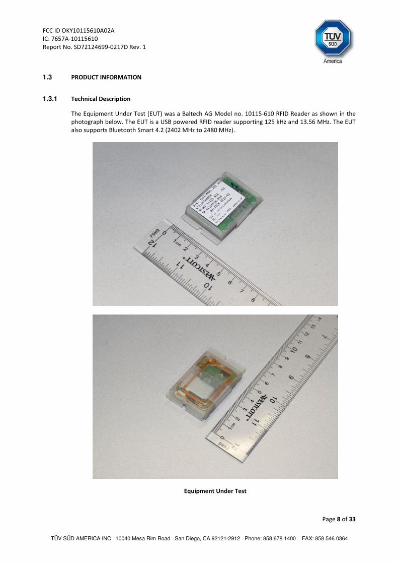
1.3 PRODUCT INFORMATION
1.3.1 Technical Description
The Equipment Under Test (EUT) was a Baltech AG Model no. 10115-610 RFID Reader as shown in the
photograph below. The EUT is a USB powered RFID reader supporting 125 kHz and 13.56 MHz. The EUT
also supports Bluetooth Smart 4.2 (2402 MHz to 2480 MHz).
Equipment Under Test

FCC ID OKY10115610A02A
IC: 7657A-10115610
Report No. SD72124699-0217D Rev. 1
Page 9 of 33
TÜV SÜD AMERICA INC 10040 Mesa Rim Road San Diego, CA 92121-2912 Phone: 858 678 1400 FAX: 858 546 0364
1.3.2 EUT General Description
EUT Description RFID Reader
Model Number(s) 10115-610
Rated Voltage 5VDC (USB)
Type Designation 10115-XYZ-A where X, Y, Z and A may be replaced by any
alphanumerical numbers:
Version/HW
Revision
10115-100 13.56MHz
10115-110
10115-200 125kHz
10115-300 125kHz & 13.56MHz
10115-310
10115-400 13.56MHz & BLE
10115-410
10115-500 125kHz & BLE
10115-510
10115-600 125kHz, 13.56MHz & BLE
10115-610
The applicant declares the conformity of the variants listed
above. The test results are valid for the tested variant
10115-610, and models listed with 125KHz Tx.
HW 10115-610
FW 1976_Test
Configuration Auto Read
Host IF USB
Frequency (Capability) 13.56 MHz, 125 KHz and 2.4 GHz
Mode Verified 125 KHz
Configuration Auto Read
Bluetooth Smart Transmit Power 3 dBm
Bluetooth Smart Conducted Power < 9.9 dBm
Bluetooth Smart Antenna Type Integrated Chip
Bluetooth Smart Antenna Gain 1 dBi

FCC ID OKY10115610A02A
IC: 7657A-10115610
Report No. SD72124699-0217D Rev. 1
Page 10 of 33
TÜV SÜD AMERICA INC 10040 Mesa Rim Road San Diego, CA 92121-2912 Phone: 858 678 1400 FAX: 858 546 0364
1.4 EUT TEST CONFIGURATION
1.4.1 Test Configuration Description
Test
Configuration Description
Default
The EUT operating at 125 kHz and 13.56 MHz sequentially once powered by 5VDC
via USB. Additionally BT functionality was turned on during RSE evaluation to verify
simultaneous Tx against 15.207 and 15.209 limits.
1.4.2 EUT Exercise Software
Testing software (3544_bluetooth_hf_test_tool_1_00_01.exe) was provided by the manufacturer to
exercise the Bluetooth function together with the RFID.
1.4.3 Support Equipment and I/O cables
Manufacturer Equipment/Cable Description
- USB Cable 1.8 meters USB Type A to Molex connector
Lenovo Support Laptop X100e Type 3508-2AU S/N LR-CHGDB 10/06
Lenovo Support AC Adapter for Laptop M/N 42T4418 S/N 11S42T4418Z1ZGWG28Z0KB
1.4.4 Simplified Test Configuration Diagrams

FCC ID OKY10115610A02A
IC: 7657A-10115610
Report No. SD72124699-0217D Rev. 1
Page 11 of 33
TÜV SÜD AMERICA INC 10040 Mesa Rim Road San Diego, CA 92121-2912 Phone: 858 678 1400 FAX: 858 546 0364
1.5 DEVIATIONS FROM THE STANDARD
All deviations made during testing from the applicable test standards or test plan are detailed under
Section 1.2 of this test report.
1.6 MODIFICATION RECORD
Description of Modification Modification
Fitted By
Date Modification
Fitted
Serial Number 00000000
N/A
The table above details modifications made to the EUT during the test programme. The modifications
incorporated during each test (if relevant) are recorded on the appropriate test pages.
1.7 TEST METHODOLOGY
All measurements contained in this report were conducted with ANSI C63.10-2013. American National
Standard of Procedures for Compliance Testing of Unlicensed Wireless Devices.
For conducted and radiated emissions the equipment under test (EUT) was configured to measure its
highest possible emission level. This level was based on the maximized cable configuration from
exploratory testing per ANSI C63.10-2013. The test modes were adapted according to the Operating
Instructions provided by the manufacturer/client.
1.8 TEST FACILITY LOCATION
1.8.1 TÜV SÜD America Inc. (Mira Mesa)
10040 Mesa Rim Road, San Diego, CA 92121-2912 (32.901268,-117.177681). Phone: 858 678 1400 Fax:
858 546 0364.
1.8.2 TÜV SÜD America Inc. (Rancho Bernardo)
16936 Via Del Campo, San Diego, CA 92127-1708 (33.018644,-117.092409). Phone: 858 678-1400 Fax:
858 546 0364.
1.9 TEST FACILITY REGISTRATION
1.9.1 FCC – Registration No.: US1146
TUV SUD America Inc. (San Diego), is an accredited test facility with the site description report on file
and has met all the requirements specified in §2.948 of the FCC rules. The acceptance letter from the
FCC is maintained in our files and the Registration is US1146.

FCC ID OKY10115610A02A
IC: 7657A-10115610
Report No. SD72124699-0217D Rev. 1
Page 12 of 33
TÜV SÜD AMERICA INC 10040 Mesa Rim Road San Diego, CA 92121-2912 Phone: 858 678 1400 FAX: 858 546 0364
1.9.2 Innovation, Science and Economic Development Canada (IC) Registration No.: 3067A
The 10m Semi-anechoic chamber of TUV SUD America Inc. (San Diego) has been registered by
Certification and Engineering Bureau of Innovation, Science and Economic Development Canada for
radio equipment testing with Registration No. 3067A.
1.9.3 BSMI – Laboratory Code: SL2-IN-E-028R (US0102)
TUV Product Service Inc. (San Diego) is a recognized EMC testing laboratory by the BSMI under the MRA
(Mutual Recognition Arrangement) with the United States. Accreditation includes CNS 13438 up to
6GHz.
1.9.4 NCC (National Communications Commission - US0102)
TUV SUD America Inc. (San Diego) is listed as a Foreign Recognized Telecommunication Equipment
Testing Laboratory and is accredited to ISO/IEC 17025 (A2LA Certificate No.2955.13) which under APEC
TEL MRA Phase 1 was designated as a Conformity Assessment Body competent to perform testing of
equipment subject to the Technical Regulations covered under its scope of accreditation including
RTTE01, PLMN01 and PLMN08 for TTE type of testing and LP002 for Low-Power RF Device type of
testing.
1.9.5 VCCI – Registration No. A-0230
TUV SUD America Inc. (San Diego) is a VCCI registered measurement facility which includes radiated field
strength measurement, radiated field strength measurement above 1GHz, mains port interference
measurement and telecommunication port interference measurement.

FCC ID OKY10115610A02A
IC: 7657A-10115610
Report No. SD72124699-0217D Rev. 1
Page 13 of 33
TÜV SÜD AMERICA INC 10040 Mesa Rim Road San Diego, CA 92121-2912 Phone: 858 678 1400 FAX: 858 546 0364
SECTION 2
TEST DETAILS
Radio Testing of the Baltech AG
10115-610

FCC ID OKY10115610A02A
IC: 7657A-10115610
Report No. SD72124699-0217D Rev. 1
Page 14 of 33
TÜV SÜD AMERICA INC 10040 Mesa Rim Road San Diego, CA 92121-2912 Phone: 858 678 1400 FAX: 858 546 0364
2.1 99% EMISSION BANDWIDTH
2.1.1 Specification Reference
RSS-Gen Clause 6.6
2.1.2 Standard Applicable
When an occupied bandwidth value is not specified in the applicable RSS, the transmitted signal
bandwidth to be reported is to be its 99% emission bandwidth, as calculated or measured.
The transmitter shall be operated at its maximum carrier power measured under normal test conditions.
The span of the analyzer shall be set to capture all products of the modulation process, including the
emission skirts. The resolution bandwidth shall be set to as close to 1% of the selected span as is
possible without being below 1%. The video bandwidth shall be set to 3 times the resolution bandwidth.
Video averaging is not permitted. Where practical, a sampling detector shall be used given that a peak
or peak hold may produce a wider bandwidth than actual.
The trace data points are recovered and directly summed in linear terms. The recovered amplitude data
points, beginning at the lowest frequency, are placed in a running sum until 0.5% of the total is reached
and that frequency recorded. The process is repeated for the highest frequency data points. This
frequency is recorded. The span between the two recorded frequencies is the occupied bandwidth.
2.1.3 Equipment Under Test and Modification State
Serial No: 00000000 / Default Test Configuration
2.1.4 Date of Test/Initial of test personnel who performed the test
March 07, 2017 /IR
2.1.5 Test Equipment Used
The major items of test equipment used for the above tests are identified in Section 3.1.
2.1.6 Environmental Conditions/ Test Location
Test performed at TÜV SÜD America Inc. Rancho Bernardo facility
Ambient Temperature
25.7 °C
Relative Humidity 44.6 %
ATM Pressure 99.8 kPa
2.1.7 Additional Observations
• This is a radiated test.
• Span is wide enough to capture the channel transmission.
• RBW was set to 1 kHz.
• VBW is 3X RBW.
• Sweep is auto.
• Detector is peak.

FCC ID OKY10115610A02A
IC: 7657A-10115610
Report No. SD72124699-0217D Rev. 1
Page 15 of 33
TÜV SÜD AMERICA INC 10040 Mesa Rim Road San Diego, CA 92121-2912 Phone: 858 678 1400 FAX: 858 546 0364
• The % Power Bandwidth setting in the spectrum analyzer was set to 99% (default).
• The Channel Bandwidth measurement function of the spectrum analyzer was used for this test.
2.1.8 Test Results (Reporting Purposes Only)
Frequency 99% Emission bandwidth
125 kHz 2.24 kHz
FCC ID OKY10115610A02A
IC: 7657A-10115610
Report No. SD72124699-0217D Rev. 1
Page 16 of 33
TÜV SÜD AMERICA INC 10040 Mesa Rim Road San Diego, CA 92121-2912 Phone: 858 678 1400 FAX: 858 546 0364
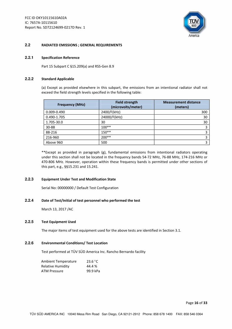
2.2 RADIATED EMISSIONS ; GENERAL REQUIREMENTS
2.2.1 Specification Reference
Part 15 Subpart C §15.209(a) and RSS-Gen 8.9
2.2.2 Standard Applicable
(a) Except as provided elsewhere in this subpart, the emissions from an intentional radiator shall not
exceed the field strength levels specified in the following table:
Frequency (MHz) Field strength
(microvolts/meter) Measurement distance
(meters)
0.009-0.490 2400/F(kHz) 300
0.490-1.705 24000/F(kHz) 30
1.705-30.0 30 30
30-88 100** 3
88-216 150** 3
216-960 200** 3
Above 960 500 3
**Except as provided in paragraph (g), fundamental emissions from intentional radiators operating
under this section shall not be located in the frequency bands 54-72 MHz, 76-88 MHz, 174-216 MHz or
470-806 MHz. However, operation within these frequency bands is permitted under other sections of
this part, e.g., §§15.231 and 15.241.
2.2.3 Equipment Under Test and Modification State
Serial No: 00000000 / Default Test Configuration
2.2.4 Date of Test/Initial of test personnel who performed the test
March 13, 2017 /AC
2.2.5 Test Equipment Used
The major items of test equipment used for the above tests are identified in Section 3.1.
2.2.6 Environmental Conditions/ Test Location
Test performed at TÜV SÜD America Inc. Rancho Bernardo facility
Ambient Temperature
23.6 °C
Relative Humidity 44.4 %
ATM Pressure 99.9 kPa

FCC ID OKY10115610A02A
IC: 7657A-10115610
Report No. SD72124699-0217D Rev. 1
Page 17 of 33
TÜV SÜD AMERICA INC 10040 Mesa Rim Road San Diego, CA 92121-2912 Phone: 858 678 1400 FAX: 858 546 0364
2.2.7 Additional Observations
• This is a radiated test. The spectrum was searched from 9 kHz to the 10th harmonic (25 GHz).
• There are no emissions found that do not comply with the restricted bands defined in FCC Part 15
Subpart C, 15.205.
• Prescans were performed to determine the best test antenna orientation with the highest
recorded emissions. Verification was performed using “Front” configuration (see the figure below)
corresponding to the best antenna orientation as found during the prescans.
• Measurement was done using EMC32 V8.53 automated software. Reported level is the actual level
with all the correction factors factored in. Correction Factor column is for informational purposes
only. See Section 2.1.8 and 2.1.9 for sample computations.
2.2.8 Sample Computation (Radiated Emission 9 kHz to 30 MHz)
Measuring equipment raw measurement (dbµV) @ 9 kHz 25.0
Correction Factor (dB)
Asset# 1057 (cable) 0.1
25.9 Asset# 8850 (cable) 0.0
Asset# 6628 (antenna) 25.8
Asset# 1026 (cable) 0.0
Reported QuasiPeak Final Measurement (dbµV/m) @ 9kHz 50.9
2.2.9 Sample Computation (Radiated Emission 30 MHz to 1 GHz)
Measuring equipment raw measurement (dbµV) @ 30 MHz 24.4
Correction Factor (dB)
Asset# 1026 (cable) 0.8
-7.0
Asset# 1057 (cable) 0.2
Asset# 1016 (preamplifier) -30.8
Asset# 8850 (cable) 0.2
Asset# 1033 (antenna) 17.2
Asset# 8771 (6-dB attenuator) 5.4
Reported QuasiPeak Final Measurement (dbµV/m) @ 30MHz 17.4
2.2.1 Test Results
See attached plots.

FCC ID OKY10115610A02A
IC: 7657A-10115610
Report No. SD72124699-0217D Rev. 1
Page 18 of 33
TÜV SÜD AMERICA INC 10040 Mesa Rim Road San Diego, CA 92121-2912 Phone: 858 678 1400 FAX: 858 546 0364
2.2.2 Test Results Below 30MHz
Quasi Peak Data (§15.209 Limits)
Frequency (MHz)
QuasiPeak (dBµV/m)
Meas. Time (ms)
Bandwidth (kHz)
Height (cm)
Polarization Azimuth
(deg) Corr. (dB)
Margin (dB)
Limit (dBµV/m)
0.013325 57.8 1000.0 0.200 100.0 V 293.0 15.4 67.3 125.1 0.091149 39.9 1000.0 0.200 100.0 V 68.0 14.5 68.5 108.4
0.124279 69.9 1000.0 0.200 100.0 V 178.0 14.2 66.0 105.7
0.806325 40.5 1500.0 9.000 100.0 V 205.0 14.4 29.0 69.5 11.061546 50.2 1500.0 9.000 100.0 V 345.0 15.4 19.4 69.5
13.561351 61.4 1500.0 9.000 100.0 V 205.0 15.4 8.1 69.5
22.359753 34.5 1500.0 9.000 100.0 V 37.0 15.0 35.0 69.5 27.651026 50.1 1500.0 9.000 100.0 V 189.0 14.2 19.4 69.5
0
20
40
60
80
100
120
140
9k 20 30 50 100k 200 300 500 1M 2M 3M 5M 10M 20 30M
Le
ve
l in
dB
µV
/m
Frequency in Hz
Discrete Rotation TUV 3m Radiated 9kHz to 30MHz..
FCC Part 15.209 Electric Field Strength @ 3m [..\EMI Radiated\]Preview Result 1V-PK+ [Preview Result 1V.Result:2]Final Result 1-QPK [Final Result 1.Result:1]
FCC Part 15.209 Electric Field Strength @ 3m

FCC ID OKY10115610A02A
IC: 7657A-10115610
Report No. SD72124699-0217D Rev. 1
Page 19 of 33
TÜV SÜD AMERICA INC 10040 Mesa Rim Road San Diego, CA 92121-2912 Phone: 858 678 1400 FAX: 858 546 0364
2.2.3 Test Results 30MHz to 1GHz
Quasi Peak Data (§15.209 Limits)
Frequency (MHz)
QuasiPeak (dBµV/m)
Meas. Time (ms)
Bandwidth (kHz)
Height (cm)
Polarization Azimuth
(deg) Corr. (dB)
Margin (dB)
Limit (dBµV/m)
51.118878 13.1 1000.0 120.000 100.0 V 344.0 -15.5 26.9 40.0
87.972745 14.1 1000.0 120.000 100.0 V 287.0 -17.1 25.9 40.0 122.746613 11.0 1000.0 120.000 100.0 V -12.0 -16.7 32.5 43.5
162.664369 16.1 1000.0 120.000 100.0 V 88.0 -13.4 27.4 43.5
189.878798 22.8 1000.0 120.000 100.0 V 215.0 -12.6 20.7 43.5 217.013226 17.4 1000.0 120.000 100.0 V 278.0 -11.5 28.6 46.0
244.067655 24.6 1000.0 120.000 100.0 V 22.0 -9.9 21.4 46.0
637.276874 30.5 1000.0 120.000 100.0 V 195.0 0.9 15.5 46.0 896.517836 23.5 1000.0 120.000 243.0 H 15.0 5.4 22.5 46.0
0
10
20
30
40
50
60
70
80
30M 50 60 80 100M 200 300 400 500 800 1G
Le
ve
l in
dB
µV
/m
Frequency in Hz
FCC Part 15 Class B Electric Field Strength QP [..\EMI radiated\]Preview Result 1V-PK+ [Preview Result 1V.Result:2]Preview Result 1H-PK+ [Preview Result 1H.Result:2]Final Result 1-QPK [Final Result 1.Result:1]
FCC Part 15 Class B Electric Field Strength QP

FCC ID OKY10115610A02A
IC: 7657A-10115610
Report No. SD72124699-0217D Rev. 1
Page 20 of 33
TÜV SÜD AMERICA INC 10040 Mesa Rim Road San Diego, CA 92121-2912 Phone: 858 678 1400 FAX: 858 546 0364
2.2.4 Test Results above 1GHz
Peak Data
Frequency (MHz)
MaxPeak (dBµV/m)
Meas. Time (ms)
Bandwidth (kHz)
Height (cm)
Polarization Azimuth
(deg) Corr. (dB)
Margin (dB)
Limit (dBµV/m)
1249.133333 53.8 1000.0 1000.000 133.7 V 55.0 -5.6 20.1 73.9 1940.300000 48.2 1000.0 1000.000 401.7 V 314.0 -2.2 25.7 73.9 2402.166667 71.6 1000.0 1000.000 102.7 H 170.0 -1.0 Fundamental BT 3198.700000 52.5 1000.0 1000.000 102.7 V -1.0 1.2 21.4 73.9 4804.433333 45.6 1000.0 1000.000 159.6 H 189.0 3.4 28.3 73.9
10007.366667 46.8 1000.0 1000.000 146.7 H 234.0 10.2 27.1 73.9 17031.533333 52.2 1000.0 1000.000 151.6 V 5.0 19.6 21.7 73.9
Average Data
Frequency (MHz)
Average (dBµV/m)
Meas. Time (ms)
Bandwidth (kHz)
Height (cm)
Polarization Azimuth
(deg) Corr. (dB)
Margin (dB)
Limit (dBµV/m)
1249.133333 28.0 1000.0 1000.000 133.7 V 55.0 -5.6 25.9 53.9
1940.300000 29.8 1000.0 1000.000 401.7 V 314.0 -2.2 24.1 53.9
2402.166667 65.5 1000.0 1000.000 102.7 H 170.0 -1.0 Fundamental BT
3198.700000 32.0 1000.0 1000.000 102.7 V -1.0 1.2 21.9 53.9
4804.433333 33.1 1000.0 1000.000 159.6 H 189.0 3.4 20.8 53.9
10007.366667 33.6 1000.0 1000.000 146.7 H 234.0 10.2 20.3 53.9
17031.533333 39.2 1000.0 1000.000 151.6 V 5.0 19.6 14.7 53.9
Test Notes: No significant emissions observed above 18GHz. Measurements above 18GHz are noise floor figures.
Fundamental of the Bluetooth Smart will be ignored for this test.
0
10
20
30
40
50
60
70
80
90
1G 2G 3G 4G 5G 6 8 10G 18G
Le
ve
l in
dB
µV
/m
Frequency in Hz
Continuous Rotation TUV 3m Radiated 1000 to 18000MHz
FCC Part 15 Class B Electric Field Strength PK above 1GHz [..\EMI radiated\]FCC Part 15 Class B Electric Field Strength AV above 1GHz [..\EMI radiated\]Preview Result 1V-PK+ [Preview Result 1V.Result:2]Preview Result 1H-PK+ [Preview Result 1H.Result:2]Final Result 1-PK+ [Final Result 1.Result:1]Final Result 2-AVG [Final Result 2.Result:1]
FCC Part 15 Class B Electric Field Strength PK above 1GHz
FCC Part 15 Class B Electric Field Strength AV above 1GHz

FCC ID OKY10115610A02A
IC: 7657A-10115610
Report No. SD72124699-0217D Rev. 1
Page 21 of 33
TÜV SÜD AMERICA INC 10040 Mesa Rim Road San Diego, CA 92121-2912 Phone: 858 678 1400 FAX: 858 546 0364
2.3 CONDUCTED EMISSIONS
2.3.1 Specification Reference
Part 15 Subpart C §15.207(a) and RSS-Gen 8.8
2.3.2 Standard Applicable
An intentional radiator that is designed to be connected to the public utility (AC) power line, the radio
frequency voltage that is conducted back onto the AC power line on any frequency or frequencies,
within the band 150 kHz to 30 MHz, shall not exceed the limits in the following table, as measured using
a 50 μH/50 ohms line impedance stabilization network (LISN).
Frequency of emission (MHz) Conducted limit (dBμV)
Quasi-peak Average
0.15–0.5 66 to 56* 56 to 46*
0.5–5 56 46
5–30 60 50
*Decreases with the logarithm of the frequency.
2.3.3 Equipment Under Test and Modification State
Serial No: 00000000 / Default Test Configuration
2.3.4 Date of Test/Initial of test personnel who performed the test
March 13, 2017 /AC
2.3.5 Test Equipment Used
The major items of test equipment used for the above tests are identified in Section 3.1.
2.3.6 Environmental Conditions/ Test Location
Test performed at TÜV SÜD America Inc. Rancho Bernardo facility
Ambient Temperature
23.6 °C
Relative Humidity 44.4 %
ATM Pressure 99.9 kPa
2.3.1 Additional Observations
• Measurement was performed on the support laptop where the EUT was connected via USB.
• Termination of the EUT RFID antenna is not possible, the position of the EUT on the test table was
adjusted to lessen the influence of the RFID frequencies on the measurements.

FCC ID OKY10115610A02A
IC: 7657A-10115610
Report No. SD72124699-0217D Rev. 1
Page 22 of 33
TÜV SÜD AMERICA INC 10040 Mesa Rim Road San Diego, CA 92121-2912 Phone: 858 678 1400 FAX: 858 546 0364
• Measurement was done using EMC32 V8.53 automated software. Reported level is the actual level
with all the correction factors factored in. Correction Factor column is for informational purposes
only. See Section 2.2.2 for sample computation.
2.3.2 Sample Computation (Conducted Emission – Quasi Peak)
Measuring equipment raw measurement (dbµV) @ 150kHz 5.5
Correction Factor (dB)
Asset# 8607 (20 dB attenuator) 19.9
20.7 Asset# 1177 (cable) 0.15
Asset# 1176 (cable) 0.35
Asset# 7568 (LISN) 0.30
Reported QuasiPeak Final Measurement (dbµV) @ 150kHz 26.2
2.3.3 Test Results
Compliant. See attached plots and tables.

FCC ID OKY10115610A02A
IC: 7657A-10115610
Report No. SD72124699-0217D Rev. 1
Page 23 of 33
TÜV SÜD AMERICA INC 10040 Mesa Rim Road San Diego, CA 92121-2912 Phone: 858 678 1400 FAX: 858 546 0364
2.3.4 120VAC 60Hz (Line 1)
Quasi Peak
Frequency (MHz)
QuasiPeak (dBµV)
Meas. Time (ms)
Bandwidth (kHz)
Filter Line Corr. (dB)
Margin - QPK (dB)
Limit - QPK
(dBµV)
0.150000 48.3 1000.0 9.000 Off L1 19.9 17.7 66.0
0.487500 29.8 1000.0 9.000 Off L1 19.9 26.4 56.2
2.148000 21.7 1000.0 9.000 Off L1 20.0 34.3 56.0 4.155000 26.8 1000.0 9.000 Off L1 20.3 29.2 56.0
12.165000 22.6 1000.0 9.000 Off L1 20.5 37.4 60.0
13.560000 54.2 1000.0 9.000 Off L1 20.5 5.8 60.0
Average
Frequency (MHz)
Average (dBµV)
Meas. Time (ms)
Bandwidth (kHz)
Filter Line Corr. (dB)
Margin - Ave (dB)
Limit - Ave (dBµV)
0.190500 35.4 1000.0 9.000 Off L1 19.8 18.4 53.9
0.492000 24.7 1000.0 9.000 Off L1 19.9 21.4 46.1
1.018500 19.3 1000.0 9.000 Off L1 19.9 26.7 46.0 3.966000 19.2 1000.0 9.000 Off L1 20.3 26.8 46.0
12.205500 17.0 1000.0 9.000 Off L1 20.5 33.0 50.0
13.560000 41.1 1000.0 9.000 Off L1 20.5 8.9 50.0
0
10
20
30
40
50
60
70
80
150k 300 400 500 800 1M 2M 3M 4M 5M 6 8 10M 20M 30M
Le
ve
l in
dB
µV
Frequency in Hz
TUV SR7 Line 1 ESCS
FCC Part 15 Class B Voltage on Mains QP [..\EMI conducted\]FCC Part 15 Class B Voltage on Mains AV [..\EMI conducted\]Preview Result 1-PK+ [Preview Result 1.Result:1]Preview Result 2-AVG [Preview Result 2.Result:2]Final Result 1-QPK [Final Result 1.Result:1]Final Result 2-AVG [Final Result 2.Result:1]
FCC Part 15 Class B Voltage on Mains QP
FCC Part 15 Class B Voltage on Mains AV

FCC ID OKY10115610A02A
IC: 7657A-10115610
Report No. SD72124699-0217D Rev. 1
Page 24 of 33
TÜV SÜD AMERICA INC 10040 Mesa Rim Road San Diego, CA 92121-2912 Phone: 858 678 1400 FAX: 858 546 0364
2.3.5 120VAC 60Hz (Line 2)
Quasi Peak
Frequency (MHz)
QuasiPeak (dBµV)
Meas. Time (ms)
Bandwidth (kHz)
Filter Line Corr. (dB)
Margin - QPK (dB)
Limit - QPK
(dBµV)
0.150000 48.5 1000.0 9.000 Off N 19.9 17.5 66.0
0.424500 24.6 1000.0 9.000 Off N 19.9 32.7 57.3 1.252500 20.7 1000.0 9.000 Off N 20.0 35.3 56.0
4.096500 25.5 1000.0 9.000 Off N 20.3 30.5 56.0
12.111000 22.9 1000.0 9.000 Off N 20.4 37.1 60.0 13.560000 54.0 1000.0 9.000 Off N 20.5 6.0 60.0
Average
Frequency (MHz)
Average (dBµV)
Meas. Time (ms)
Bandwidth (kHz)
Filter Line Corr. (dB)
Margin - Ave (dB)
Limit - Ave (dBµV)
0.190500 32.8 1000.0 9.000 Off N 19.9 21.0 53.9
0.492000 24.9 1000.0 9.000 Off N 19.9 21.3 46.1
1.117500 17.4 1000.0 9.000 Off N 19.9 28.6 46.0 4.195500 16.5 1000.0 9.000 Off N 20.3 29.5 46.0
12.003000 17.1 1000.0 9.000 Off N 20.4 32.9 50.0
13.564500 36.5 1000.0 9.000 Off N 20.5 13.5 50.0
0
10
20
30
40
50
60
70
80
150k 300 400 500 800 1M 2M 3M 4M 5M 6 8 10M 20M 30M
Le
ve
l in
dB
µV
Frequency in Hz
TUV SR7 Line 2 ESCS
FCC Part 15 Class B Voltage on Mains QP [..\EMI conducted\]FCC Part 15 Class B Voltage on Mains AV [..\EMI conducted\]Preview Result 1-PK+ [Preview Result 1.Result:1]Preview Result 2-AVG [Preview Result 2.Result:2]Final Result 1-QPK [Final Result 1.Result:1]Final Result 2-AVG [Final Result 2.Result:1]
FCC Part 15 Class B Voltage on Mains QP
FCC Part 15 Class B Voltage on Mains AV

FCC ID OKY10115610A02A
IC: 7657A-10115610
Report No. SD72124699-0217D Rev. 1
Page 25 of 33
TÜV SÜD AMERICA INC 10040 Mesa Rim Road San Diego, CA 92121-2912 Phone: 858 678 1400 FAX: 858 546 0364
SECTION 3
TEST EQUIPMENT USED
FCC ID OKY10115610A02A
IC: 7657A-10115610
Report No. SD72124699-0217D Rev. 1
Page 26 of 33
TÜV SÜD AMERICA INC 10040 Mesa Rim Road San Diego, CA 92121-2912 Phone: 858 678 1400 FAX: 858 546 0364
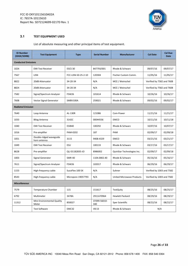
3.1 TEST EQUIPMENT USED
List of absolute measuring and other principal items of test equipment.
ID Number (SDGE/SDRB)
Test Equipment Type Serial Number Manufacturer Cal Date Cal Due
Date
Conducted Emissions
1024 EMI Test Receiver ESCS 30 847793/001 Rhode & Schwarz 09/07/16 09/07/17
7567 LISN FCC-LISN-50-25-2-10 120304 Fischer Custom Comm. 11/05/16 11/05/17
8822 20dB Attenuator 34-20-34 N/A MCE / Weinschel Verified by 7582 and 7608
8824 20dB Attenuator 34-20-34 N/A MCE / Weinschel Verified by 7582 and 7608
7582 Signal/Spectrum Analyzer FSW26 101614 Rhode & Schwarz 10/26/16 10/26/17
7608 Vector Signal Generator SMBV100A 259021 Rhode & Schwarz 09/02/16 09/02/17
Radiated Emission
7640 Loop Antenna AL-130R 121086 Com-Power 11/21/16 11/21/17
1033 Bilog Antenna 3142C 00044556 EMCO 10/11/16 10/11/18
1040 EMI Test Receiver ESIB40 100292 Rhode & Schwarz 10/07/16 10/07/17
1016 Pre-amplifier PAM-0202 187 PAM 02/09/17 02/09/18
1051 Double-ridged waveguide horn antenna
3115 9408-4329 EMCO 03/21/16 03/21/17
1049 EMI Test Receiver ESU 100133 Rhode & Schwarz 03/17/16 03/17/17
8628 Pre-amplifier QLJ 01182835-JO 8986002 QuinStar Technologies Inc. 02/09/17 02/09/18
1003 Signal Generator SMR-40 1104.0002.40 Rhode & Schwarz 05/16/16 05/16/17
7611 Signal/Spectrum Analyzer FSW26 102017 Rhode & Schwarz 06/29/16 06/29/17
1153 High-frequency cable SucoFlex 100 SX N/A Suhner Verified by 1003 and 7582
8543 High-frequency cable Micropore 19057793 N/A United Microwave Products Verified by 1003 and 7582
Miscellaneous
7579 Temperature Chamber 115 151617 TestQuity 08/25/16 08/25/17
6792 Multimeter 3478A 2911A70964 Hewlett Packard 08/29/16 08/29/17
11312 Mini Environmental Quality
Meter 850027
CF099-56010-
340 Sper Scientific 08/22/16 08/22/17
Test Software EMC32 V8.53 Rhode & Schwarz N/A

FCC ID OKY10115610A02A
IC: 7657A-10115610
Report No. SD72124699-0217D Rev. 1
Page 27 of 33
TÜV SÜD AMERICA INC 10040 Mesa Rim Road San Diego, CA 92121-2912 Phone: 858 678 1400 FAX: 858 546 0364
3.2 MEASUREMENT UNCERTAINTY
For a 95% confidence level, the measurement uncertainties for defined systems are:
3.2.1 Radiated Measurements (Below 30MHz)
Contribution
Probability Distribution
Type
Probability Distribution
xi
Standard Uncertainty
u(xi) [u(xi)]2
1 Receiver/Spectrum Analyzer Rectangular 0.45 0.26 0.07
2 Cables Rectangular 0.50 0.29 0.08
4 Loop Antenna Rectangular 0.75 0.44 0.19
5 Site Rectangular 2.70 1.56 2.43
6 EUT Setup Rectangular 1.00 0.58 0.33
Combined Uncertainty (uc): 1.76
Coverage Factor (k): 2
Expanded Uncertainty: 3.53
3.2.2 Radiated Measurements (30 MHz to 1GHz)
Contribution
Probability Distribution
Type
Probability Distribution
xi
Standard Uncertainty
u(xi) [u(xi)]2
1 Receiver/Spectrum Analyzer Rectangular 0.45 0.26 0.07
2 Cables Rectangular 0.50 0.29 0.08
3 Preamp Rectangular 0.50 0.29 0.08
4 Antenna Rectangular 0.75 0.43 0.19
5 Site Rectangular 2.70 1.56 2.43
6 EUT Setup Rectangular 1.00 0.58 0.33
Combined Uncertainty (uc): 1.78
Coverage Factor (k): 2
Expanded Uncertainty: 3.57
3.2.3 Radiated Emission Measurements (Above 1GHz)
Contribution
Probability Distribution
Type Probability
Distribution xi
Standard Uncertainty
u(xi) [u(xi)]2
1 Receiver/Spectrum Analyzer Rectangular 0.57 0.33 0.11
2 Cables Rectangular 0.70 0.40 0.16
3 Preamp Rectangular 0.50 0.29 0.08
4 Antenna Rectangular 0.37 0.21 0.05
5 Site Rectangular 2.70 1.56 2.43
6 EUT Setup Rectangular 1.00 0.58 0.33
Combined Uncertainty (uc): 1.78
Coverage Factor (k): 2
Expanded Uncertainty: 3.56
FCC ID OKY10115610A02A
IC: 7657A-10115610
Report No. SD72124699-0217D Rev. 1
Page 28 of 33
TÜV SÜD AMERICA INC 10040 Mesa Rim Road San Diego, CA 92121-2912 Phone: 858 678 1400 FAX: 858 546 0364
SECTION 4
DIAGRAM OF TEST SETUP

FCC ID OKY10115610A02A
IC: 7657A-10115610
Report No. SD72124699-0217D Rev. 1
Page 29 of 33
TÜV SÜD AMERICA INC 10040 Mesa Rim Road San Diego, CA 92121-2912 Phone: 858 678 1400 FAX: 858 546 0364
4.1 TEST SETUP DIAGRAM (BELOW 30MHZ)

FCC ID OKY10115610A02A
IC: 7657A-10115610
Report No. SD72124699-0217D Rev. 1
Page 30 of 33
TÜV SÜD AMERICA INC 10040 Mesa Rim Road San Diego, CA 92121-2912 Phone: 858 678 1400 FAX: 858 546 0364
4.2 TEST SETUP DIAGRAM (30MHZ TO 1GHZ)
Radiated Emission Test Setup (Below 1GHz)

FCC ID OKY10115610A02A
IC: 7657A-10115610
Report No. SD72124699-0217D Rev. 1
Page 31 of 33
TÜV SÜD AMERICA INC 10040 Mesa Rim Road San Diego, CA 92121-2912 Phone: 858 678 1400 FAX: 858 546 0364
4.3 TEST SETUP DIAGRAM (> 1GHZ)
Radiated Emission Test Setup (Above 1GHz)

FCC ID OKY10115610A02A
IC: 7657A-10115610
Report No. SD72124699-0217D Rev. 1
Page 32 of 33
TÜV SÜD AMERICA INC 10040 Mesa Rim Road San Diego, CA 92121-2912 Phone: 858 678 1400 FAX: 858 546 0364
SECTION 5
ACCREDITATION, DISCLAIMERS AND COPYRIGHT

FCC ID OKY10115610A02A
IC: 7657A-10115610
Report No. SD72124699-0217D Rev. 1
Page 33 of 33
TÜV SÜD AMERICA INC 10040 Mesa Rim Road San Diego, CA 92121-2912 Phone: 858 678 1400 FAX: 858 546 0364
A2LA Cert. No. 2955.13
5.1 ACCREDITATION, DISCLAIMERS AND COPYRIGHT
TÜV SÜD America Inc.’s reports apply only to the specific sample tested under stated test
conditions. It is the manufacturer’s responsibility to assure the continued compliance of
production units of this model. TÜV SÜD America, Inc. shall have no liability for any deductions,
inferences or generalizations drawn by the client or others from TÜV SÜD America, Inc.’s issued
reports.
This report is the confidential property of the client. As a mutual protection to our clients, the
public and TÜV SÜD America, Inc., extracts from the test report shall not be reproduced, except
in full without TÜV SÜD America, Inc.’s written approval.
This report must not be used to claim product certification, approval, or endorsement by
A2LA, NIST, or any agency of the federal government.
TÜV SÜD America, Inc. and its professional staff hold government
and professional organization certifications for
AAMI, ACIL, AEA, ANSI, IEEE, A2LA, NIST and VCCI.