Report on Advanced Robotics & Programming
38
1 Report (Advanced Robotics) Submitted By ASEEM ANAND (Electronics & Communication Engineering)
-
Upload
surya-world-institutions-of-academic-excellence -
Category
Engineering
-
view
44 -
download
2
Transcript of Report on Advanced Robotics & Programming
1
Report
(Advanced Robotics)
Submitted By
ASEEM ANAND
(Electronics & Communication Engineering)
2
Declaration
I, Aseem Anand hereby declare that the work which is being presented in this project report titled
“Advanced Robotics” by me, in partial fulfillment of the requirements for the award of B.Tech Degree
in “Electronics & Communication Engineering”, is an authentic record of my own work carried out.
To the best of my knowledge, the matter embodied in this report has not been submitted to any other
University/ Institute for the award of any degree or diploma.
Aseem Anand
3
Acknowledgement
It is a pleasure to acknowledge many people who knowingly and unwittingly helped us, to complete this
report.
I express my gratitude to TIMTS (Times Institute of Management and Technical Studies) for
providing lots of material and knowledge.
I would like to expresses my gratitude towards All India Council of Robotics & Automation (AICRA) to
give us complete practical platform for learning, implementing and completing this report.
Aseem Anand
4
List of Figures
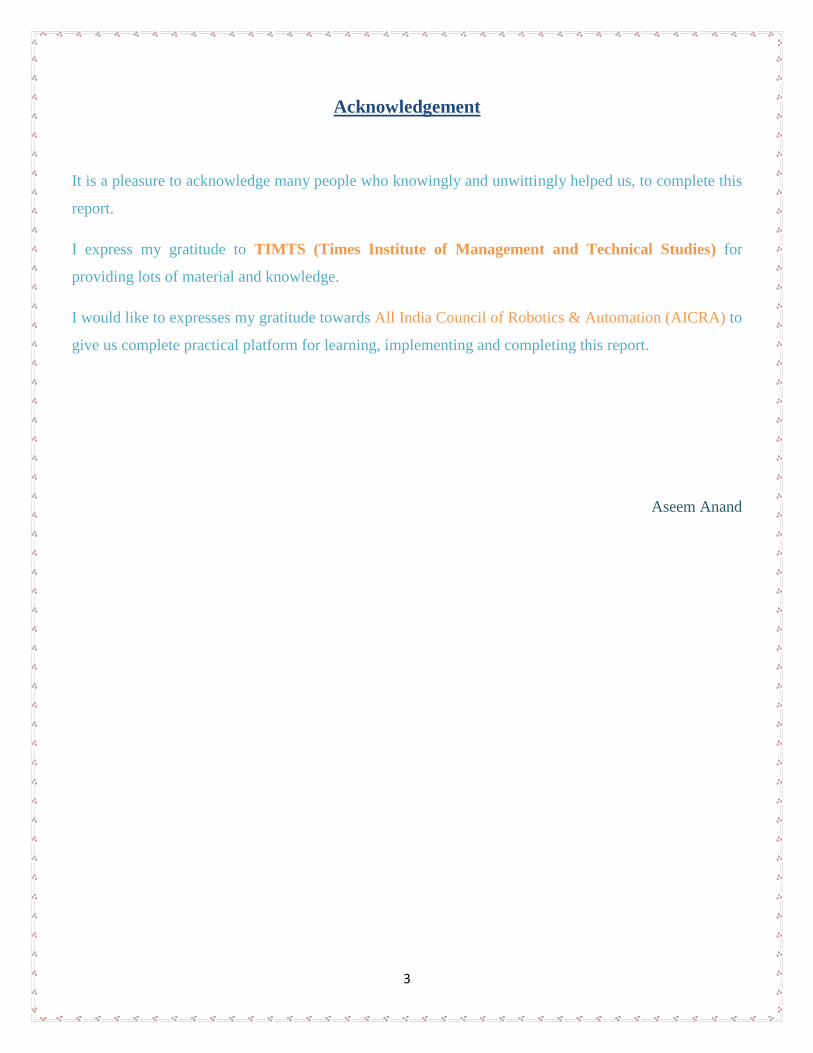
AVR DEVELOPMENT BOARD
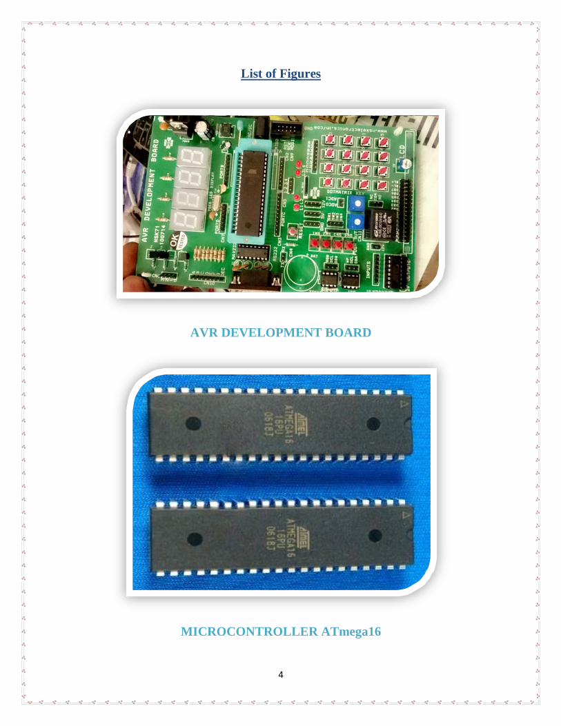
MICROCONTROLLER ATmega16
5
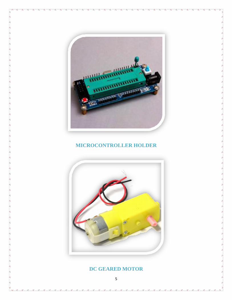
MICROCONTROLLER HOLDER
DC GEARED MOTOR
6
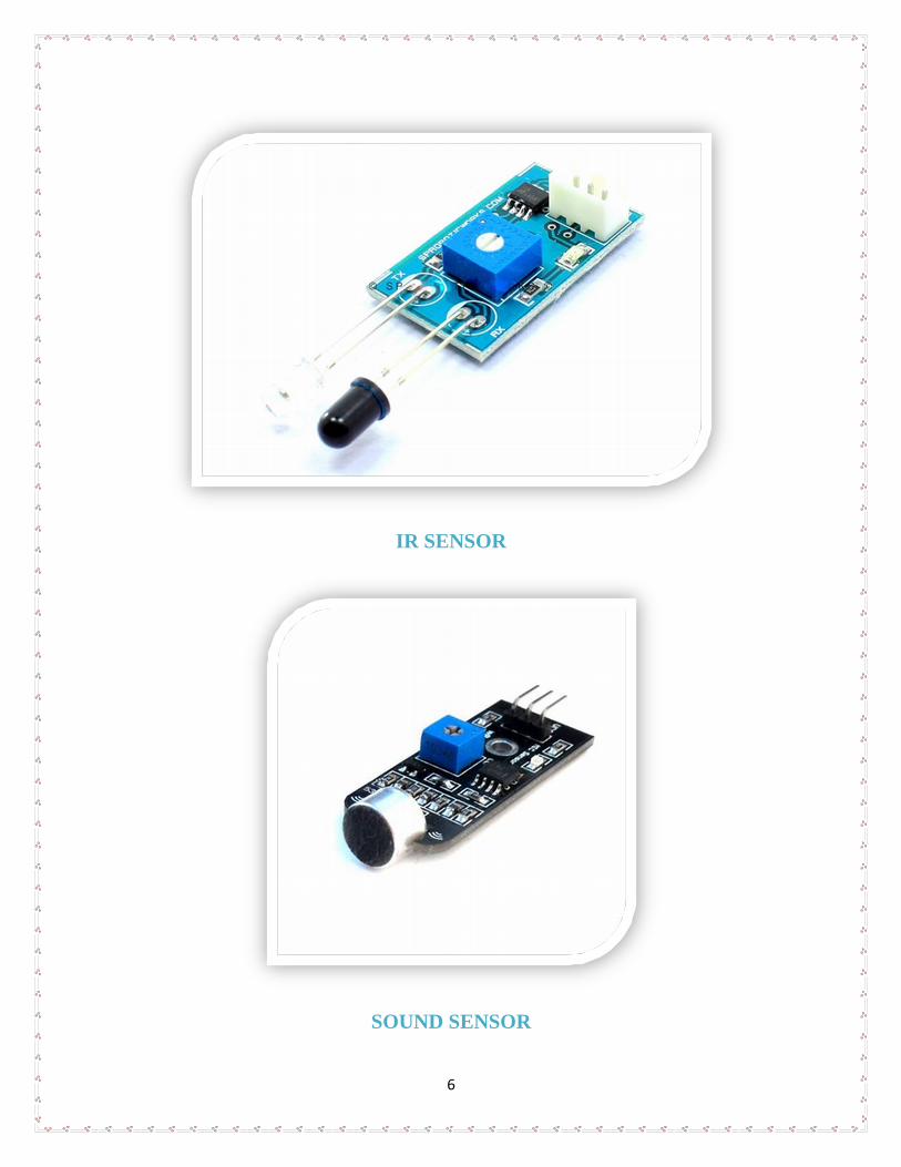
IR SENSOR
SOUND SENSOR
7
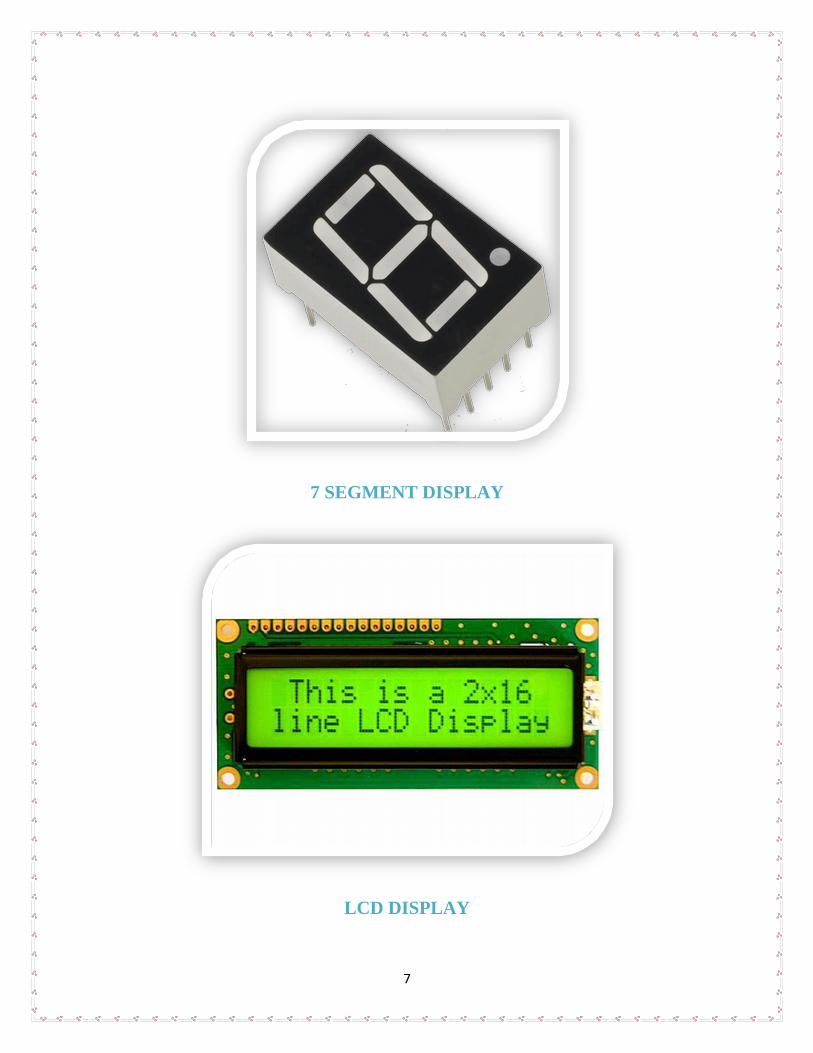
7 SEGMENT DISPLAY
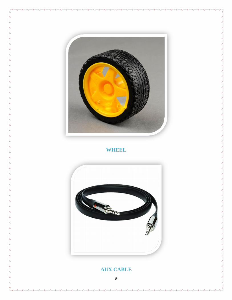
LCD DISPLAY
8
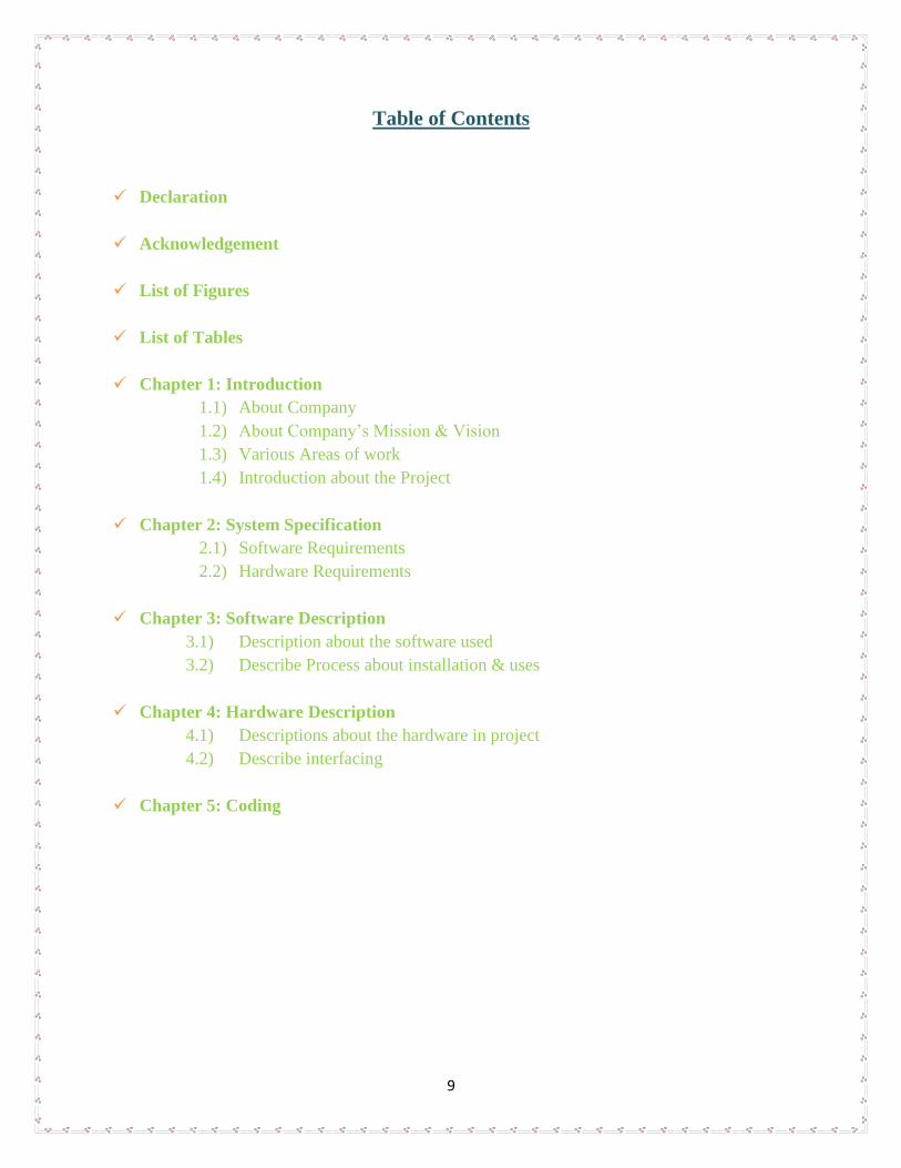
WHEEL
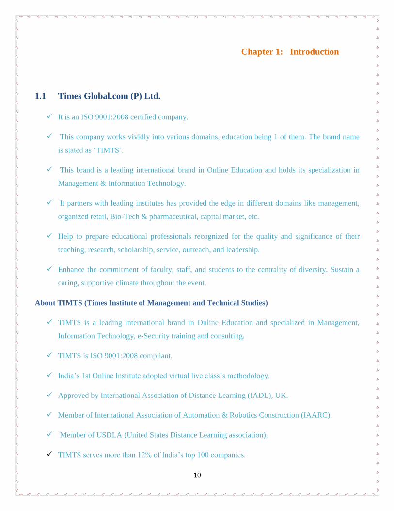
AUX CABLE
9
Table of Contents
Declaration
Acknowledgement
List of Figures
List of Tables
Chapter 1: Introduction
1.1) About Company
1.2) About Company’s Mission & Vision
1.3) Various Areas of work
1.4) Introduction about the Project
Chapter 2: System Specification
2.1) Software Requirements
2.2) Hardware Requirements
Chapter 3: Software Description
3.1) Description about the software used
3.2) Describe Process about installation & uses
Chapter 4: Hardware Description
4.1) Descriptions about the hardware in project
4.2) Describe interfacing
Chapter 5: Coding
10
Chapter 1: Introduction
1.1 Times Global.com (P) Ltd.
It is an ISO 9001:2008 certified company.
This company works vividly into various domains, education being 1 of them. The brand name
is stated as ‘TIMTS’.
This brand is a leading international brand in Online Education and holds its specialization in
Management & Information Technology.
It partners with leading institutes has provided the edge in different domains like management,
organized retail, Bio-Tech & pharmaceutical, capital market, etc.
Help to prepare educational professionals recognized for the quality and significance of their
teaching, research, scholarship, service, outreach, and leadership.
Enhance the commitment of faculty, staff, and students to the centrality of diversity. Sustain a
caring, supportive climate throughout the event.
About TIMTS (Times Institute of Management and Technical Studies)
TIMTS is a leading international brand in Online Education and specialized in Management,
Information Technology, e-Security training and consulting.
TIMTS is ISO 9001:2008 compliant.
India’s 1st Online Institute adopted virtual live class’s methodology.
Approved by International Association of Distance Learning (IADL), UK.
Member of International Association of Automation & Robotics Construction (IAARC).
Member of USDLA (United States Distance Learning association).
TIMTS serves more than 12% of India’s top 100 companies.

11
1.2 About Company’s Mission & Vision
Mission:
The mission of the College of Education is to help prepare outstanding educators, scholars, and
researchers, and to advance the profession of education, as broadly defined, through research on the
science and art of teaching and learning, the application of clinical processes, the effective uses of
technology, and the analysis and development of leadership and educational policy.
Vision:
The College of Education will be a world leader in the integration of
(a) teaching and learning,
(b) advancement of the knowledge base through research and scholarship, and
(c) leadership in service and outreach.
Further, the College will be a world leader in preparing professionals who provide leadership and
exemplary educational and related services to improve the lives of individuals in a changing and
complex global society.
1.3 Various Services provided by the Company:
Robotics Lab
Research Work
Online Electronics Store – Robohaat.com
Workshops, Summer Training, Winter Training
Industrial Solution
Engineering Solution
Training and Certification
Job Oriented Program
12
Chapter 2: System Specification
2.1 Software Requirements
Atmel Studio 6.0
Win AVR
USBASP Driver
AVR Burn-O-Mat
2.2 Hardware Requirements
AVR Development Board
Microcontroller (ATMEGA16A)
Motors
IR Sensors
Sound Sensors
7 Segment Display
LCD
Wheels
Connecting Wires
Data Cable
AUX Cable
13
Chapter 3: Software Description
3.1 Description about the software used
Atmel Studio 6.0:
Atmel® Studio 6 is the integrated development platform (IDP) for developing and debugging Atmel
ARM® Cortex®-M and Atmel AVR® microcontroller (MCU) based applications. The Atmel Studio 6
IDP gives you a seamless and easy-to-use environment to write, build and debug your applications
written in C/C++ or assembly code.
Gain insight into the run-time of embedded software with trace visualization. Percepio Trace for Atmel
Studio features:
Control-flow trace (tasks and interrupts)
Custom data plots
Application debug output
Statistical code profiling
Support for viewing MCU event counters
Real-time operating system (RTOS) awareness
WinAVR:
WinAVRTM is a suite of executable, open source software development tools for the Atmel AVR series
of RISC microprocessors hosted on the Windows platform. It includes the GNU GCC compiler for C
and C++.
WinAVRTM contains all the tools for developing on the AVR. This includes avr-gcc (compiler), avrdude
(programmer), avr-gdb (debugger), and more! WinAVR is used all over the world from hobbyists sitting
in their damp basements, to schools, to commercial projects.
WinAVRTM is comprised of many open source projects. If you feel adventurous, volunteers are always
welcome to help with fixing bugs, adding features, porting, writing documentation and many other tasks
on a variety of projects.
USBASP Driver:
USBasp is a USB in-circuit programmer for Atmel AVR controllers. It simply consists of an ATMega88
or an ATMega8 and a couple of passive components. The programmer uses a firmware-only USB
driver, no special USB controller is needed.
14
Features
Works under multiple platforms. Linux, Mac OS X and Windows are tested.
No special controllers or smd components are needed.
Programming speed is up to 5kBytes/sec.
SCK option to support targets with low clock speed (< 1,5MHz).
Planned: serial interface to target (e.g. for debugging).
AVR Burn-O-Mat:
AVR Burn-O-Mat is a cross-platform GUI for avrdude written in JAVA. It simplifies programing and
configuration of AVR microcontrollers with easy to use dialogs. The program offers support for several
microcontrollers, such as ATmega8, ATmega16, ATmega32, ATmega64, ATmega128, ATmega48,
ATmega88, ATmega168, ATmega162, ATmega8515, ATmega8335, ATmega164, ATmega324, and
others.
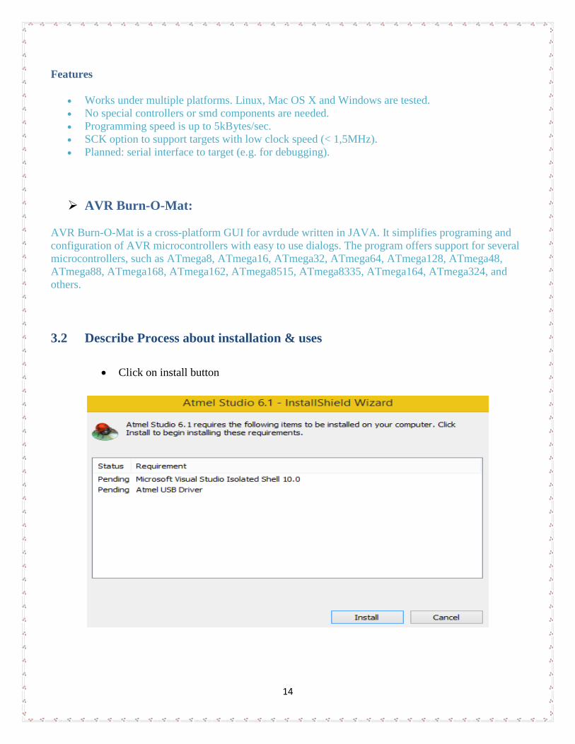
3.2 Describe Process about installation & uses
Click on install button
15
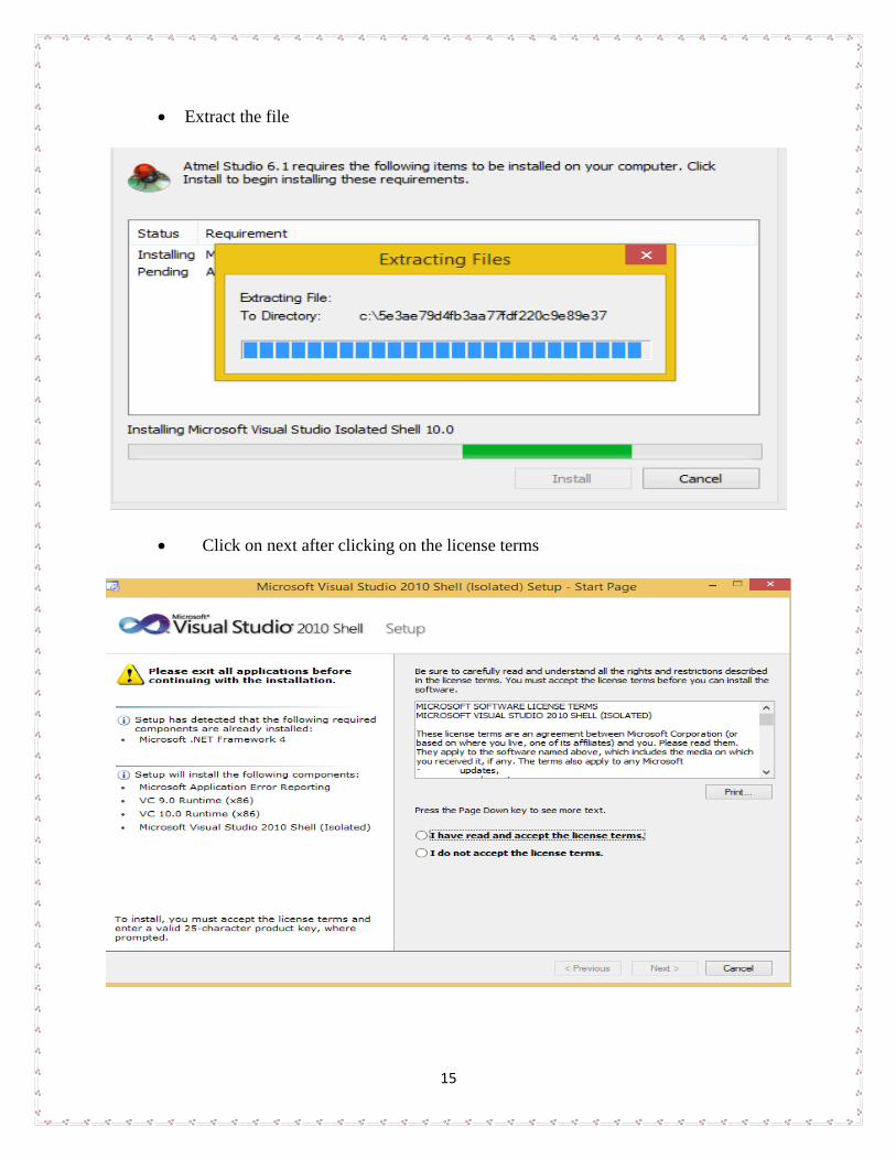
Extract the file
Click on next after clicking on the license terms
16
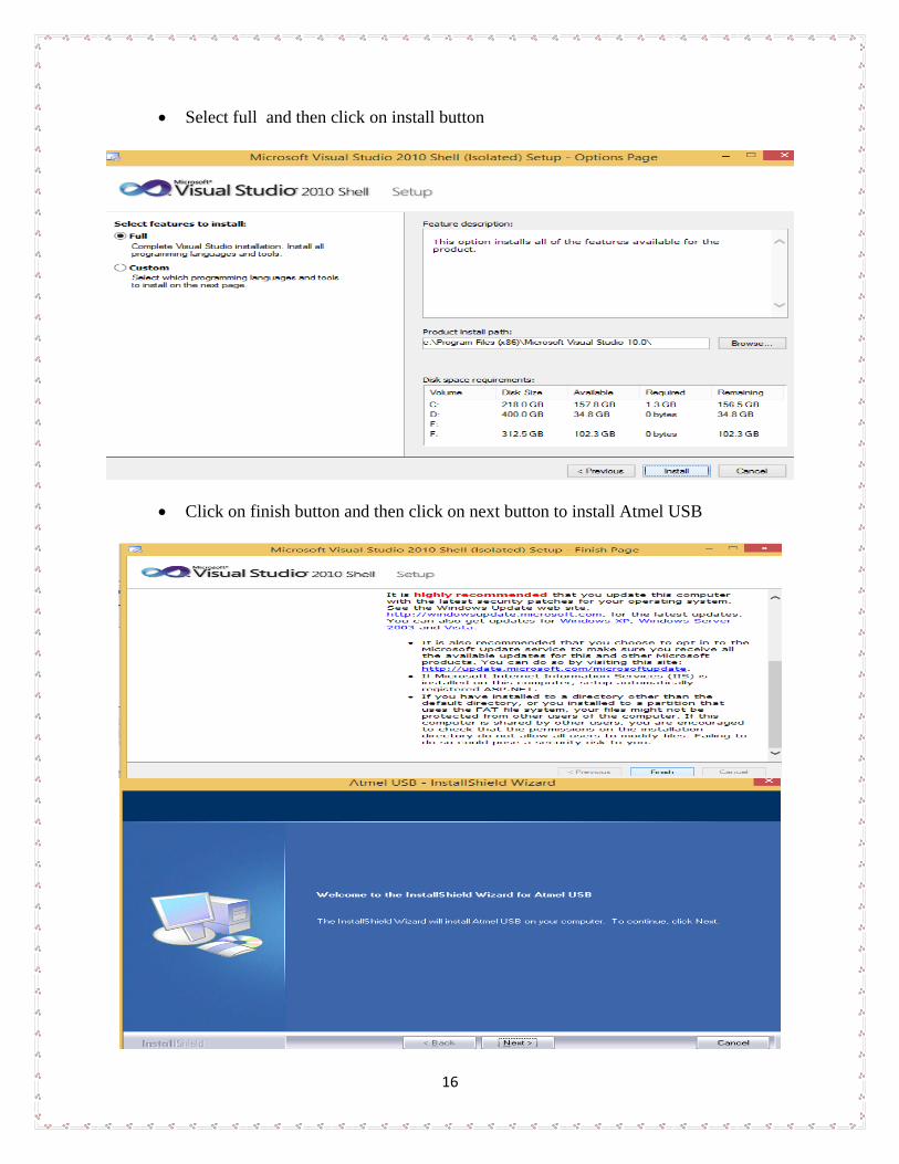
Select full and then click on install button
Click on finish button and then click on next button to install Atmel USB

17
Click On License Then Next And Then Click On Install Button
18
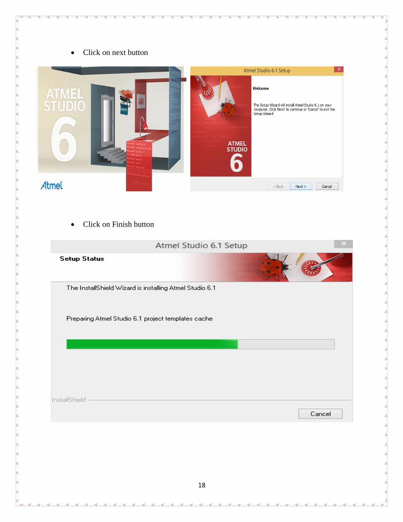
Click on next button
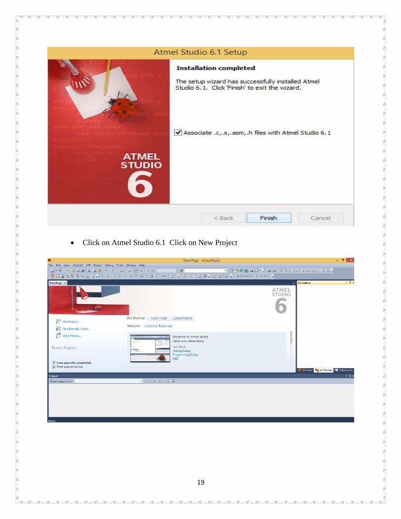
Click on Finish button
19
Click on Atmel Studio 6.1 Click on New Project
20
Chapter 4: Hardware Description
4.1 Descriptions about the hardware in project
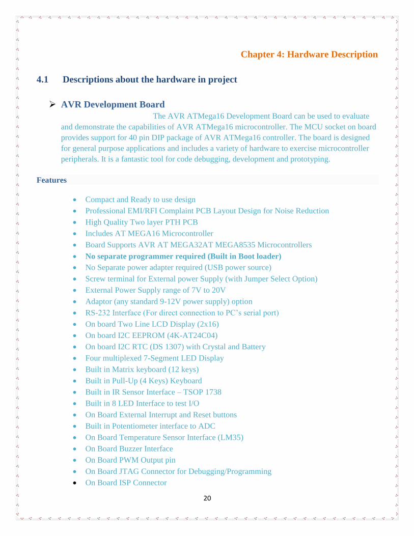
AVR Development Board
The AVR ATMega16 Development Board can be used to evaluate
and demonstrate the capabilities of AVR ATMega16 microcontroller. The MCU socket on board
provides support for 40 pin DIP package of AVR ATMega16 controller. The board is designed
for general purpose applications and includes a variety of hardware to exercise microcontroller
peripherals. It is a fantastic tool for code debugging, development and prototyping.
Features
Compact and Ready to use design
Professional EMI/RFI Complaint PCB Layout Design for Noise Reduction
High Quality Two layer PTH PCB
Includes AT MEGA16 Microcontroller
Board Supports AVR AT MEGA32AT MEGA8535 Microcontrollers
No separate programmer required (Built in Boot loader)
No Separate power adapter required (USB power source)
Screw terminal for External power Supply (with Jumper Select Option)
External Power Supply range of 7V to 20V
Adaptor (any standard 9-12V power supply) option
RS-232 Interface (For direct connection to PC’s serial port)
On board Two Line LCD Display (2x16)
On board I2C EEPROM (4K-AT24C04)
On board I2C RTC (DS 1307) with Crystal and Battery
Four multiplexed 7-Segment LED Display
Built in Matrix keyboard (12 keys)
Built in Pull-Up (4 Keys) Keyboard
Built in IR Sensor Interface – TSOP 1738
Built in 8 LED Interface to test I/O
On Board External Interrupt and Reset buttons
Built in Potentiometer interface to ADC
On Board Temperature Sensor Interface (LM35)
On Board Buzzer Interface
On Board PWM Output pin
On Board JTAG Connector for Debugging/Programming
On Board ISP Connector
21
On Board 16 MHz Crystal Oscillator
On Board Power LED Indicator
On Board DB9 Connector
On Board USB Connector
All Port Pins available at IDC (2x5) Connector
Can be used as main board for developing applications
Power Supply Reverse Polarity Protection
On Board 1 Amp Voltage Regulator
Demo HEX codes included for testing of board features
Example codes included
Microcontroller ATMega16A
Atmel AVR AT Mega16 with 16 MHz Crystal Oscillator (With Boot loader Software)
16 K bytes programmable flash
1 K bytes SRAM
512 bytes EEPROM
16 MHz operation (Up to 16 MIPS)
32 I/O pins
8 channel 10 bit ADC
4 PWM Channels
Two 8-Bit Timer/Counter
One 16-Bit Timer/Counter
One Serial USART
1 Two Wire Serial Interface TWI
SPI Master/ Slave
Power Consumption
14 mA
Operating voltage -2.7-5.5V for ATmega16L
-4.5-5.5V for ATmega16
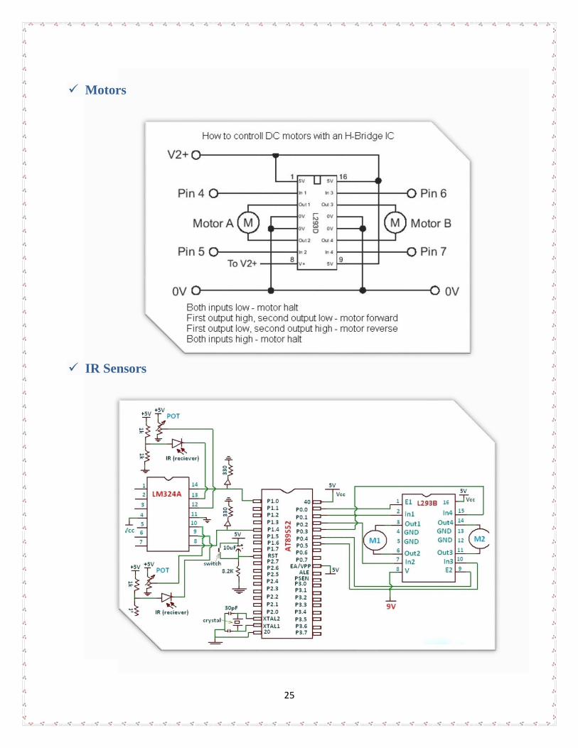
Motors It is an arrangement of coils and magnets that converts electric current (ac or dc) into
mechanical rotation. In a motor, practically all of the electromechanical energy conversion takes
place in the air gap, using magnetic fields as the energy link between the electrical input and the
mechanical output. The air-gap magnetic field is set up by current-carrying windings located on
the stator. The magnetic field exerts force on the rotor to produce the mechanical torque, on the
shaft connected to the rotor.
22
Types
AC motors
DC motors
DC geared motors
Stepper motors
Servo motors
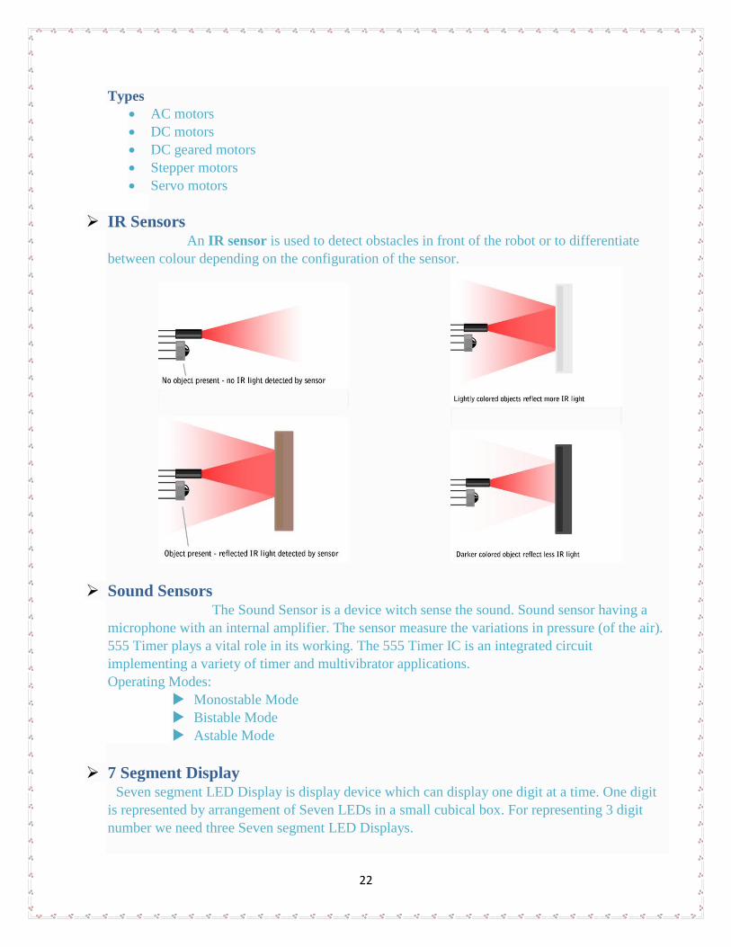
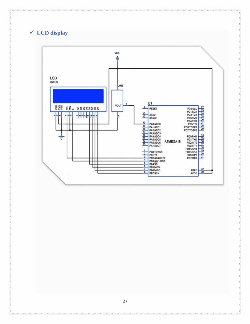
IR Sensors An IR sensor is used to detect obstacles in front of the robot or to differentiate
between colour depending on the configuration of the sensor.
Sound Sensors The Sound Sensor is a device witch sense the sound. Sound sensor having a
microphone with an internal amplifier. The sensor measure the variations in pressure (of the air).
555 Timer plays a vital role in its working. The 555 Timer IC is an integrated circuit
implementing a variety of timer and multivibrator applications. Operating Modes:
Monostable Mode
Bistable Mode
Astable Mode
7 Segment Display Seven segment LED Display is display device which can display one digit at a time. One digit
is represented by arrangement of Seven LEDs in a small cubical box. For representing 3 digit
number we need three Seven segment LED Displays.
23
Types
Common Cathode
Common Anode
Common Cathode
We need to provide +5 V to other open ends to turn ON that particular
segments. We need to provide 0 V to other open ends to turn OFF that particular segments.
Common Anode
We need to provide +5 V to other open ends to turn OFF that particular
segments. We need to provide 0 V to other open ends to turn ON that particular segments.
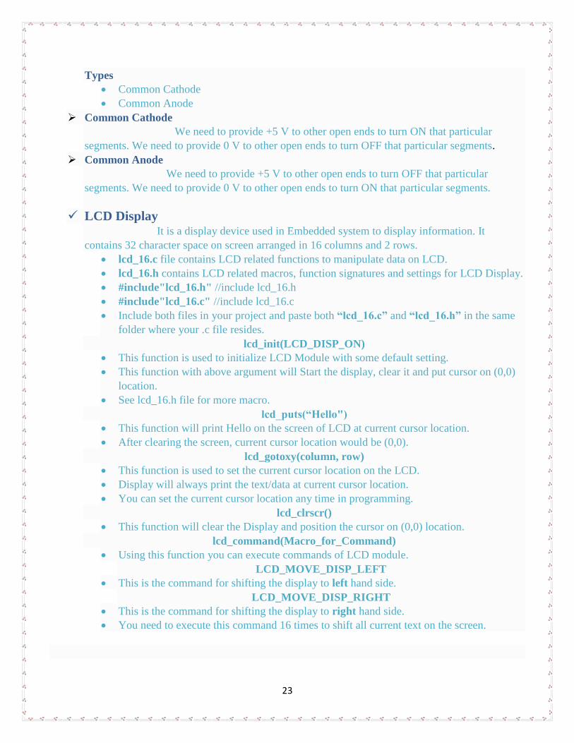
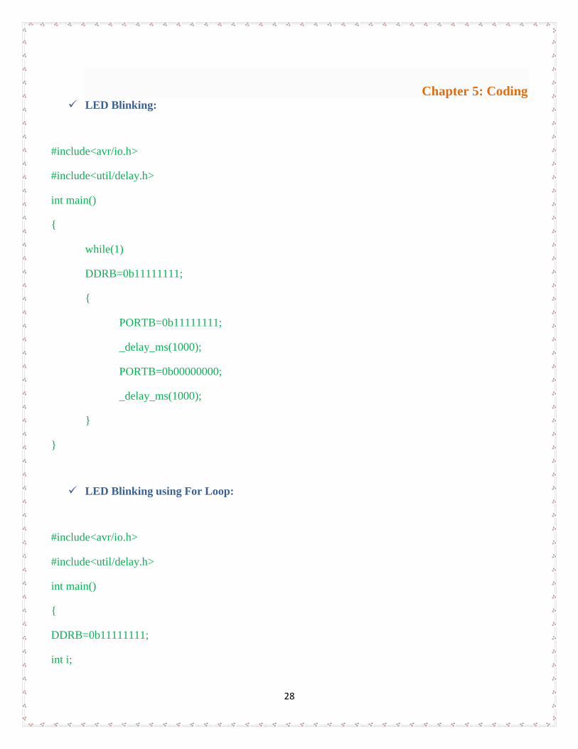
LCD Display It is a display device used in Embedded system to display information. It
contains 32 character space on screen arranged in 16 columns and 2 rows.
lcd_16.c file contains LCD related functions to manipulate data on LCD.
lcd_16.h contains LCD related macros, function signatures and settings for LCD Display.
#include"lcd_16.h" //include lcd_16.h
#include"lcd_16.c" //include lcd_16.c
Include both files in your project and paste both “lcd_16.c” and “lcd_16.h” in the same
folder where your .c file resides.
lcd_init(LCD_DISP_ON)
This function is used to initialize LCD Module with some default setting.
This function with above argument will Start the display, clear it and put cursor on (0,0)
location.
See lcd_16.h file for more macro.
lcd_puts(“Hello")
This function will print Hello on the screen of LCD at current cursor location.
After clearing the screen, current cursor location would be (0,0).
lcd_gotoxy(column, row)
This function is used to set the current cursor location on the LCD.
Display will always print the text/data at current cursor location.
You can set the current cursor location any time in programming.
lcd_clrscr()
This function will clear the Display and position the cursor on (0,0) location.
lcd_command(Macro_for_Command)
Using this function you can execute commands of LCD module.
LCD_MOVE_DISP_LEFT
This is the command for shifting the display to left hand side.
LCD_MOVE_DISP_RIGHT
This is the command for shifting the display to right hand side.
You need to execute this command 16 times to shift all current text on the screen.
24
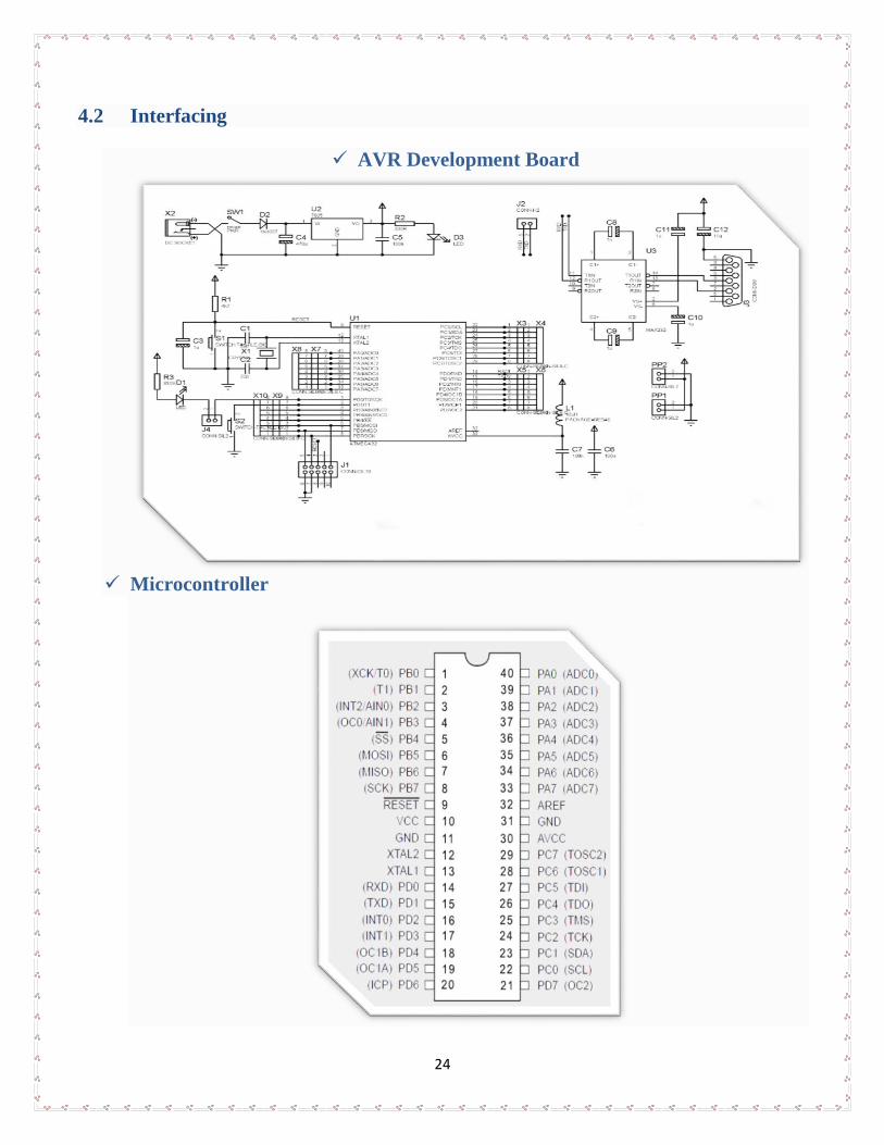
4.2 Interfacing
AVR Development Board
Microcontroller
25
Motors
IR Sensors

26
Sound Sensor
7 Segment Display
27
LCD display
28
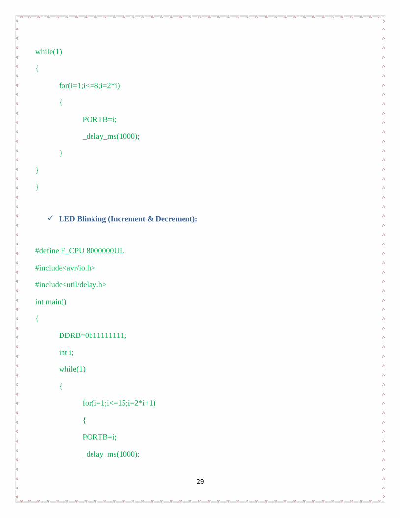
Chapter 5: Coding LED Blinking:
#include<avr/io.h>
#include<util/delay.h>
int main()
{
while(1)
DDRB=0b11111111;
{
PORTB=0b11111111;
_delay_ms(1000);
PORTB=0b00000000;
_delay_ms(1000);
}
}
LED Blinking using For Loop:
#include<avr/io.h>
#include<util/delay.h>
int main()
{
DDRB=0b11111111;
int i;
29
while(1)
{
for(i=1;i<=8;i=2*i)
{
PORTB=i;
_delay_ms(1000);
}
}
}
LED Blinking (Increment & Decrement):
#define F_CPU 8000000UL
#include<avr/io.h>
#include<util/delay.h>
int main()
{
DDRB=0b11111111;
int i;
while(1)
{
for(i=1;i<=15;i=2*i+1)
{
PORTB=i;
_delay_ms(1000);
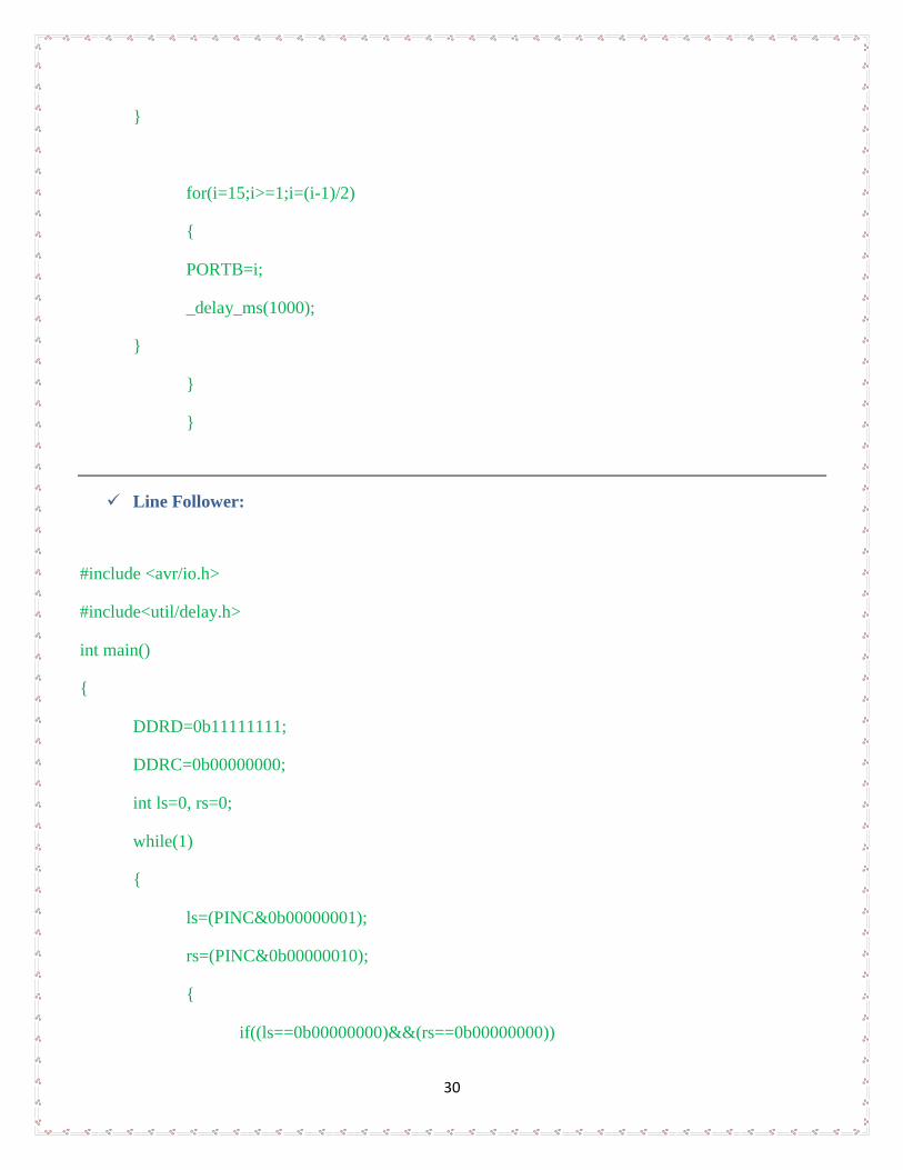
30
}
for(i=15;i>=1;i=(i-1)/2)
{
PORTB=i;
_delay_ms(1000);
}
}
}
Line Follower:
#include <avr/io.h>
#include<util/delay.h>
int main()
{
DDRD=0b11111111;
DDRC=0b00000000;
int ls=0, rs=0;
while(1)
{
ls=(PINC&0b00000001);
rs=(PINC&0b00000010);
{
if((ls==0b00000000)&&(rs==0b00000000))
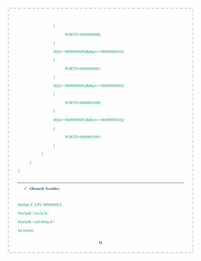
31
{
PORTD=0b00000000;
}
if((ls==0b00000000)&&(rs==0b00000010))
{
PORTD=0b00000001;
}
if((ls==0b00000001)&&(rs==0b00000000))
{
PORTD=0b00001000;
}
if((ls==0b00000001)&&(rs==0b00000010))
{
PORTD=0b00001001;
}
}
}
}
Obstacle Avoider:
#define F_CPU 8000000UL
#include <avr/io.h>
#include <util/delay.h>
int main()
32
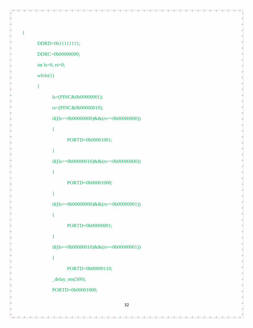
{
DDRD=0b11111111;
DDRC=0b00000000;
int ls=0, rs=0;
while(1)
{
ls=(PINC&0b00000001);
rs=(PINC&0b00000010);
if((ls==0b00000000)&&(rs==0b00000000))
{
PORTD=0b00001001;
}
if((ls==0b00000010)&&(rs==0b00000000))
{
PORTD=0b00001000;
}
if((ls==0b00000000)&&(rs==0b00000001))
{
PORTD=0b00000001;
}
if((ls==0b00000010)&&(rs==0b00000001))
{
PORTD=0b00000110;
_delay_ms(500);
PORTD=0b00001000;
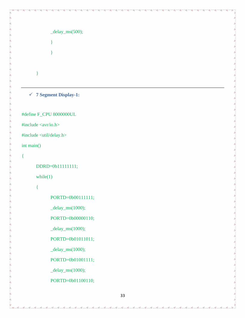
33
_delay_ms(500);
}
}
}
7 Segment Display-1:
#define F_CPU 8000000UL
#include <avr/io.h>
#include <util/delay.h>
int main()
{
DDRD=0b11111111;
while(1)
{
PORTD=0b00111111;
_delay_ms(1000);
PORTD=0b00000110;
_delay_ms(1000);
PORTD=0b01011011;
_delay_ms(1000);
PORTD=0b01001111;
_delay_ms(1000);
PORTD=0b01100110;
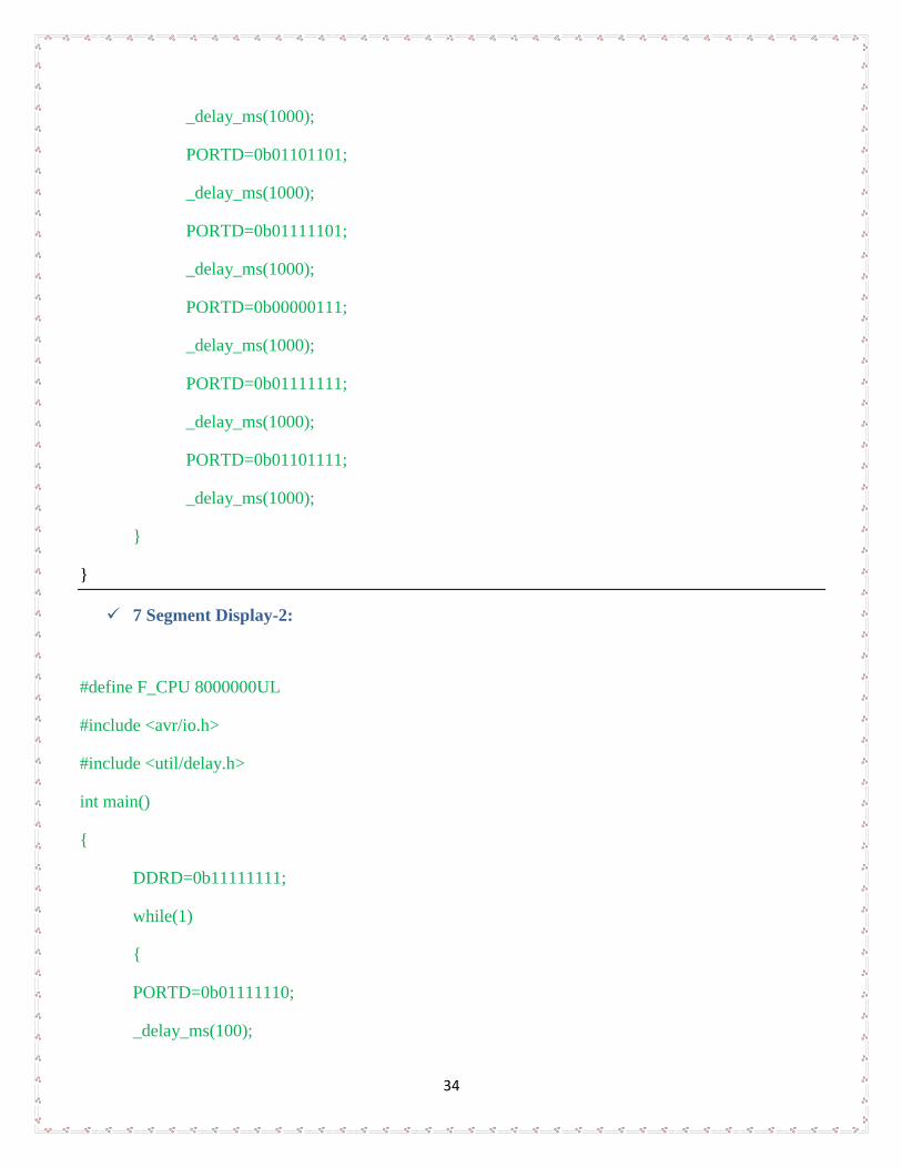
34
_delay_ms(1000);
PORTD=0b01101101;
_delay_ms(1000);
PORTD=0b01111101;
_delay_ms(1000);
PORTD=0b00000111;
_delay_ms(1000);
PORTD=0b01111111;
_delay_ms(1000);
PORTD=0b01101111;
_delay_ms(1000);
}
}
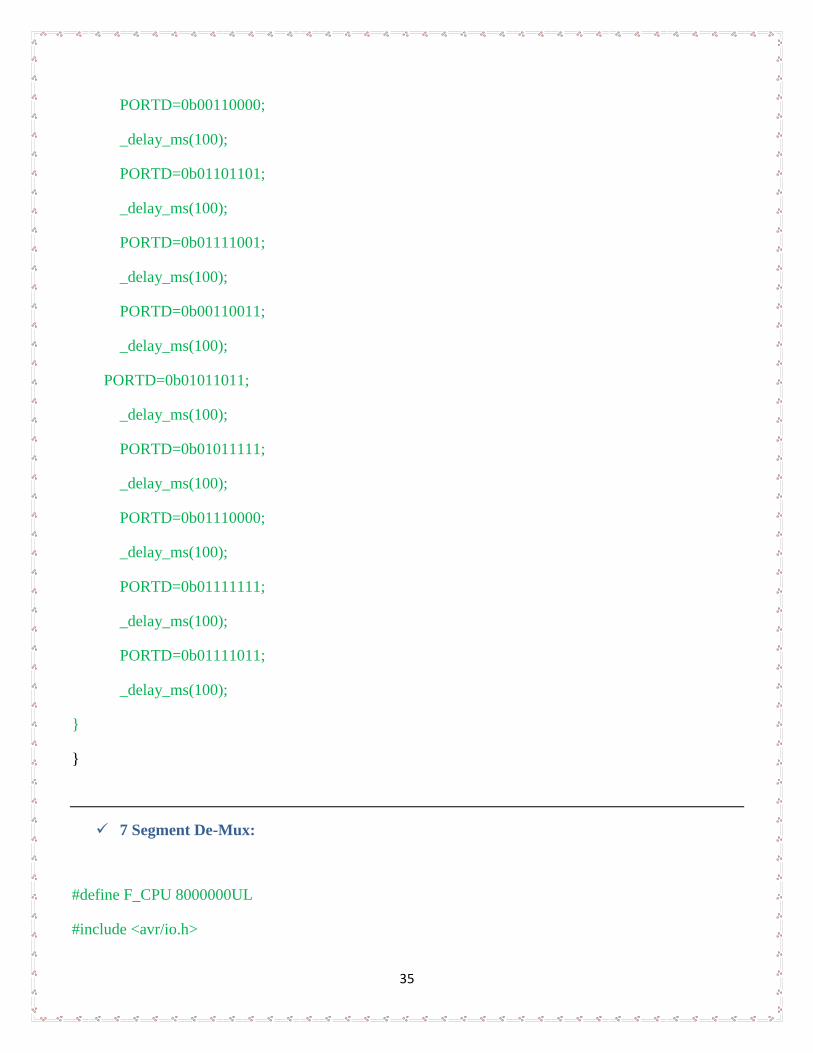
7 Segment Display-2:
#define F_CPU 8000000UL
#include <avr/io.h>
#include <util/delay.h>
int main()
{
DDRD=0b11111111;
while(1)
{
PORTD=0b01111110;
_delay_ms(100);
35
PORTD=0b00110000;
_delay_ms(100);
PORTD=0b01101101;
_delay_ms(100);
PORTD=0b01111001;
_delay_ms(100);
PORTD=0b00110011;
_delay_ms(100);
PORTD=0b01011011;
_delay_ms(100);
PORTD=0b01011111;
_delay_ms(100);
PORTD=0b01110000;
_delay_ms(100);
PORTD=0b01111111;
_delay_ms(100);
PORTD=0b01111011;
_delay_ms(100);
}
}
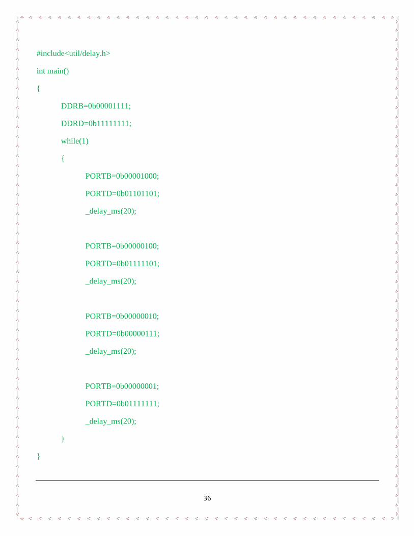
7 Segment De-Mux:
#define F_CPU 8000000UL
#include <avr/io.h>
36
#include<util/delay.h>
int main()
{
DDRB=0b00001111;
DDRD=0b11111111;
while(1)
{
PORTB=0b00001000;
PORTD=0b01101101;
_delay_ms(20);
PORTB=0b00000100;
PORTD=0b01111101;
_delay_ms(20);
PORTB=0b00000010;
PORTD=0b00000111;
_delay_ms(20);
PORTB=0b00000001;
PORTD=0b01111111;
_delay_ms(20);
}
}
37
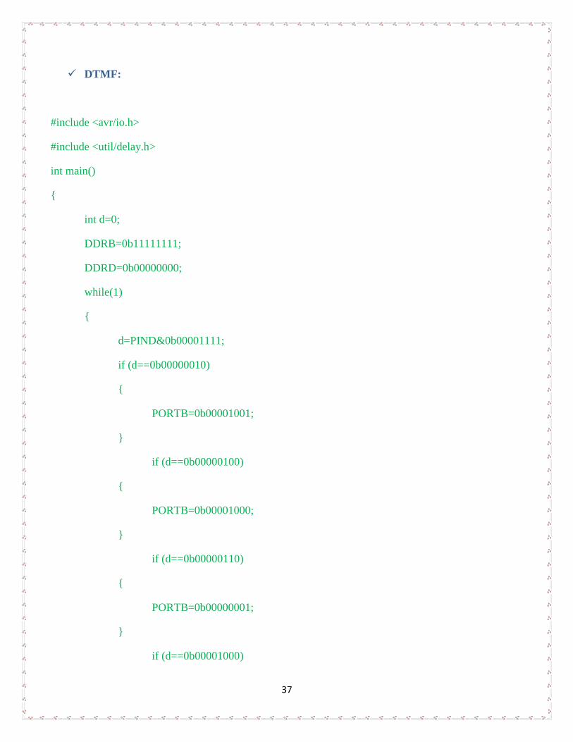
DTMF:
#include <avr/io.h>
#include <util/delay.h>
int main()
{
int d=0;
DDRB=0b11111111;
DDRD=0b00000000;
while(1)
{
d=PIND&0b00001111;
if (d==0b00000010)
{
PORTB=0b00001001;
}
if (d==0b00000100)
{
PORTB=0b00001000;
}
if (d==0b00000110)
{
PORTB=0b00000001;
}
if (d==0b00001000)
38
{
PORTB=0b00000110;
}
if (d==0b00000101)
{
PORTB=0b00000000;
}
}
}
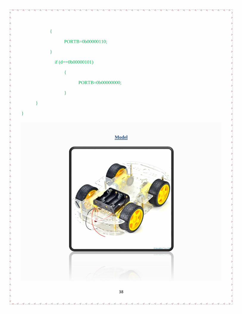
Model