Report on 220kv substation at Jassure
26
REPORT INDUSTRIAL TRAINING At 220/132/33 KV Grid Sub Station HPSEBL Jassure BY: SHUVAM PATHANIA Reg. No.: 1051330033 DEGREE: B.tech (IV Semester) DEPARTMENT: Electrical and Electronics Engineering (EEE) INSTITUTION: SRM University, Delhi NCR Campus
-
Upload
shuvam-pathania -
Category
Engineering
-
view
1.135 -
download
11
Transcript of Report on 220kv substation at Jassure
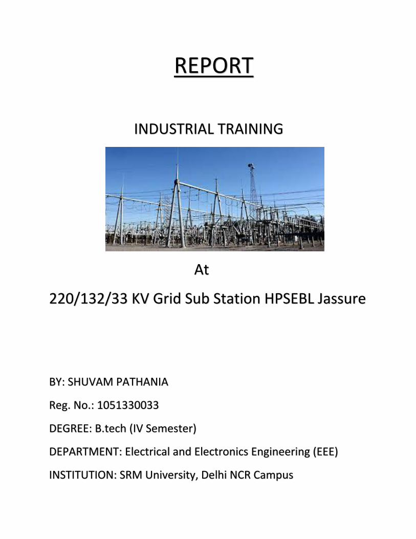
REPORT
INDUSTRIAL TRAINING
At
220/132/33 KV Grid Sub Station HPSEBL Jassure
BY: SHUVAM PATHANIA
Reg. No.: 1051330033
DEGREE: B.tech (IV Semester)
DEPARTMENT: Electrical and Electronics Engineering (EEE)
INSTITUTION: SRM University, Delhi NCR Campus
Acknowledgement
This report is an outcome of the contributions made by some
people. I am greatly thankful to sincere efforts made by Mr.
Ravinder Kumar ( Assistant Executive Engineer) . I am also
thankful to the staff members of the 220/132/33 KV Grid Sub
Station HPSEBL Jassure , who took out their precious time to
introduce me the various equipments.
I am also thankful to my parents, who paved the way for me to
overcome this industrial training.
CERTIFICATE
Signature/Date
Mr. Ravinder Kumar (AEE)
CONTENTS
1) General introduction to Sub Station.
2) Functions of a sub station
3) SLD of a substation
4) Elements of a sub station
I. Lightning areester
II. CVT
III. Wave Trap
IV. Circuit Breaker
V. Isolating Switch
VI. CT
VII. PT
5) Functions of the associated systems in a sub station
6) Overview about Jassure Sub Station
7) SLD of the Jassure Substation
8) Feeder circuit of the Sub Station
9) Site selection for the Substaion
10) Conclusion
BY- SHUVAM PATHANIA
ELECTRICAL SUBSTATION
A substation is type of grid where electrical supply from different
power sources are grouped and amended as per requirement to
be transmitted. A substation is a part of an
electrical generation, transmission, and distribution system.
Substations transform voltage from high to low, or the
reverse, or perform any of several other important functions.
Between the generating station and consumer, electric
power may flow through several substations at different
voltage levels.A substation may include transformers to
change voltage levels between high transmission voltages
and lower distribution voltages, or at the interconnection of
two different transmission voltages. The
word substation comes from the days before the distribution
system became a grid. As central generation stations
became larger, smaller generating plants were converted to
distribution stations, receiving their energy supply from a
larger plant instead of using their own generators.
BY- SHUVAM PATHANIA
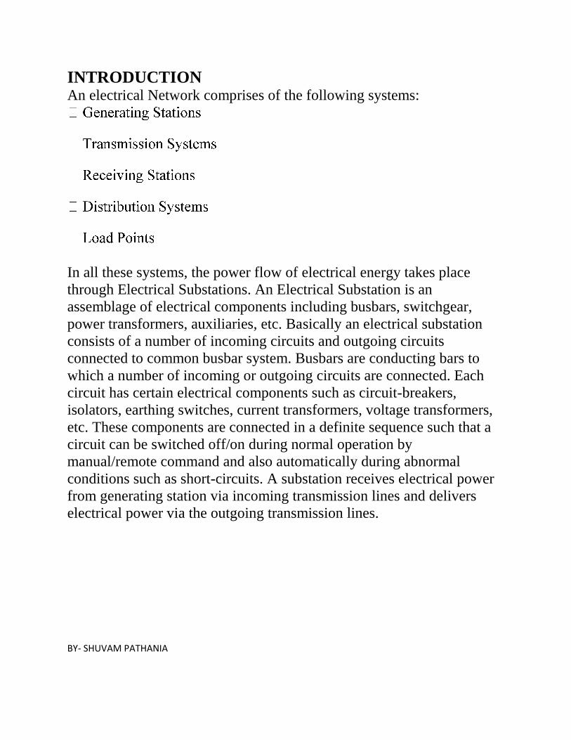
INTRODUCTION An electrical Network comprises of the following systems:
In all these systems, the power flow of electrical energy takes place
through Electrical Substations. An Electrical Substation is an
assemblage of electrical components including busbars, switchgear,
power transformers, auxiliaries, etc. Basically an electrical substation
consists of a number of incoming circuits and outgoing circuits
connected to common busbar system. Busbars are conducting bars to
which a number of incoming or outgoing circuits are connected. Each
circuit has certain electrical components such as circuit-breakers,
isolators, earthing switches, current transformers, voltage transformers,
etc. These components are connected in a definite sequence such that a
circuit can be switched off/on during normal operation by
manual/remote command and also automatically during abnormal
conditions such as short-circuits. A substation receives electrical power
from generating station via incoming transmission lines and delivers
electrical power via the outgoing transmission lines.
BY- SHUVAM PATHANIA
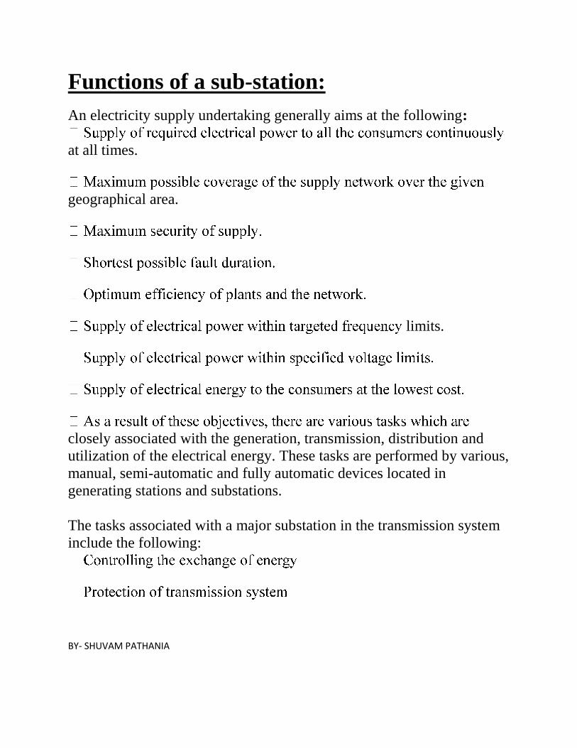
Functions of a sub-station:
An electricity supply undertaking generally aims at the following:
at all times.
geographical area.
limits.
closely associated with the generation, transmission, distribution and
utilization of the electrical energy. These tasks are performed by various,
manual, semi-automatic and fully automatic devices located in
generating stations and substations.
The tasks associated with a major substation in the transmission system
include the following:
BY- SHUVAM PATHANIA
ning the system frequency within targeted limits
reactive power, tap-changing.
for changing the transmission paths.
monitoring, control and protection.
-
lines.
-pointing the cause and subsequent
improvements.
All these tasks are performed by the team work of load-control centre
and control rooms of substations. The substations perform several
important tasks and are integral part of the power system.
BY- SHUVAM PATHANIA
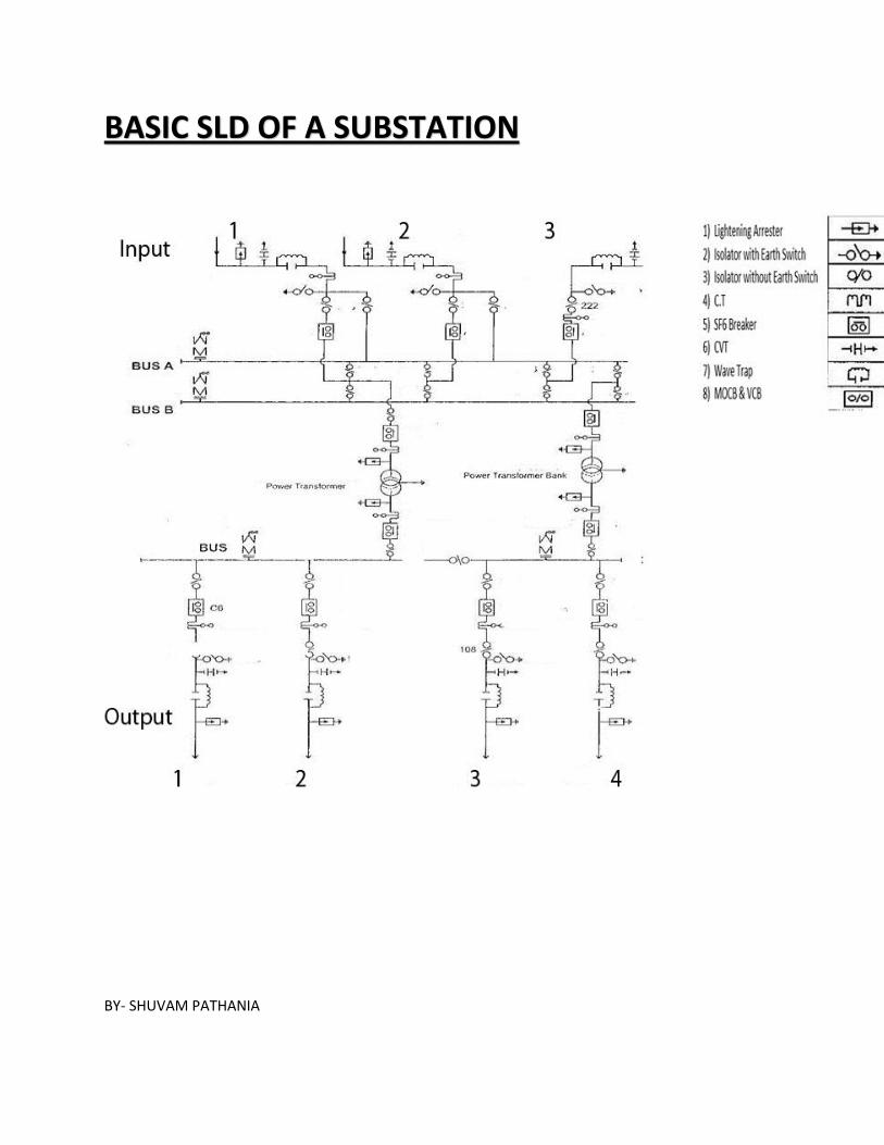
BASIC SLD OF A SUBSTATION
BY- SHUVAM PATHANIA
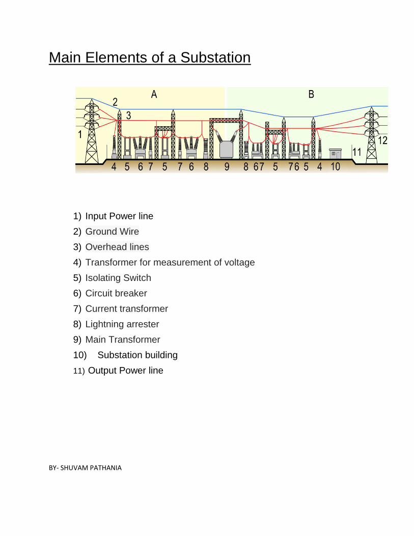
Main Elements of a Substation
1) Input Power line
2) Ground Wire
3) Overhead lines
4) Transformer for measurement of voltage
5) Isolating Switch
6) Circuit breaker
7) Current transformer
8) Lightning arrester
9) Main Transformer
10) Substation building
11) Output Power line
BY- SHUVAM PATHANIA
1. LIGTHNING ARRESTOR It is the first equipment in a substation. Substation design involves more than one
installing apparatus, protective devices and equipment. The significant momentary
investment and required reliable continuous operation of the facility requires
detailed attention to preventing surges from entering the substation facility. The
effects of disturbances with limiting in a power system, which
if allowed to persist, may damage plant and interrupt the supply of electrical
energy. Lightning is one of the most serious causes of over voltage. If the power
equipment especially at outdoor substation is not protected, the over-voltage will
cause burning of insulation. Thus it results into complete shutdown of the power
and the loss may run into cores of kyat. Electrical equipment can be damaged due
to over-voltage such as switching surge over-voltage, Lightning surge over-
voltage, transient recovery voltage and power frequency temporary over-voltage in
transmission line and receiving end of substation. It is important to protect power
equipment against them wherever possible. Lightning Arrester can protect the
damages of electrical equipments. So, Lightning Arrester must be installed at the
terminal end of the transmission line, substation, high voltage transformers and low
voltage transformer. The analysis of electromagnetic transient is depended on
operating voltage, lengths of the lines and contactor configuration. So, it can be
chosen correctly the technical specifications of the apparatus of Lightning Arrester
base on the amounts of receiving overvoltage. Generally arresters are connected in
parallel with the equipment to be protected, typically between phase and earth for
three phase installations.
The functions of a lightning arrester are
1. To act like an open circuit during the normal operation of the system i.e., to hold
off the system voltage,
2. To limit the transient voltage to a safe level with the minimum delay and fitter,
and
3. To bring the system back to its normal operation mode as soon as the transient
voltage is suppressed, i.e., to interrupt the power-follow current and to reseal itself.
BY- SHUVAM PATHANIA
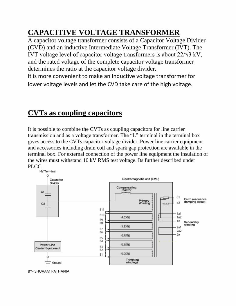
CAPACITIVE VOLTAGE TRANSFORMER
A capacitor voltage transformer consists of a Capacitor Voltage Divider
(CVD) and an inductive Intermediate Voltage Transformer (IVT). The
IVT voltage level of capacitor voltage transformers is about 22/√3 kV,
and the rated voltage of the complete capacitor voltage transformer
determines the ratio at the capacitor voltage divider.
It is more convenient to make an Inductive voltage transformer for
lower voltage levels and let the CVD take care of the high voltage.
CVTs as coupling capacitors
It is possible to combine the CVTs as coupling capacitors for line carrier
transmission and as a voltage transformer. The “L” terminal in the terminal box
gives access to the CVTs capacitor voltage divider. Power line carrier equipment
and accessories including drain coil and spark gap protection are available in the
terminal box. For external connection of the power line equipment the insulation of
the wires must withstand 10 kV RMS test voltage. Its further described under
PLCC.
BY- SHUVAM PATHANIA
WAVE TRAP
It is also called "LINE trap". It is connected in series with the power line. It blocks
the high frequency carrier waves (24 kHz to 500 kHz) and let power waves (50 Hz -
60 Hz) to pass through. It is basically an inductor of rating in milli henry.
CIRCUIT BREAKER
The circuit breaker operates as a single pressure puffer breaker with two
interrupting chambers for each pole. For short circuit interruption the puffer
breaker utilizes the drive energy in combination with the arc energy to generate the
arc quenching gas flow.
Two interrupting unit is fitted in each of the three single-phase aluminum
enclosures. The breaker is provided with a hydraulic spring operating mechanism
for each phase. It is normally mounted horizontally on a steel bay structure.
The high-current connections from the interrupting unit to the flanges are designed
as knife contact (at the drive side) and as plug contact (at the fixed contact side).
This allows the interrupting unit to be pulled out of the tank through the drive side
flange without removing the connections.
The operating mechanism combines the advantage of mechanical energy storage in
plate-shaped springs with the advantages of a hydraulic energy transmission. The
plate-shaped springs feature long-time stability, very high reliability and are
independent from temperature changes. The hydraulic cylinder is based on existing
and well proven design elements for hydraulic drives. The overall number of
sealing points has been reduced to an absolute minimum. Sliding seals under
pressure are arranged so the leaking oil is kept in the low pressure hydraulic
system.
They are a. SF6 circuit breakers b. Spring circuit breakers.
The use of SF6 circuit breaker is mainly in the substations which are having
high input kv input, say above 220kv and more. The gas is put inside the circuit
breaker by force i.e. under high pressure. When if the gas gets decreases there is a
motor connected to the circuit breaker. The motor starts operating if the gas went
lower than 20.8 bar. There is a meter connected to the breaker so that it can be
manually seen if the gas goes low. The circuit breaker uses the SF6 gas to reduce the
torque produce in it due to any fault in the line. The circuit breaker has a direct link
with the instruments in the station, when any fault occur alarm bell rings. The spring type of circuit breakers is used for small kv stations. The spring
here reduces the torque produced so that the breaker can function again. The spring
type is used for step down side of 132kv to 33kv also in 33kv to 11kv and so on.
They are only used in low distribution side.
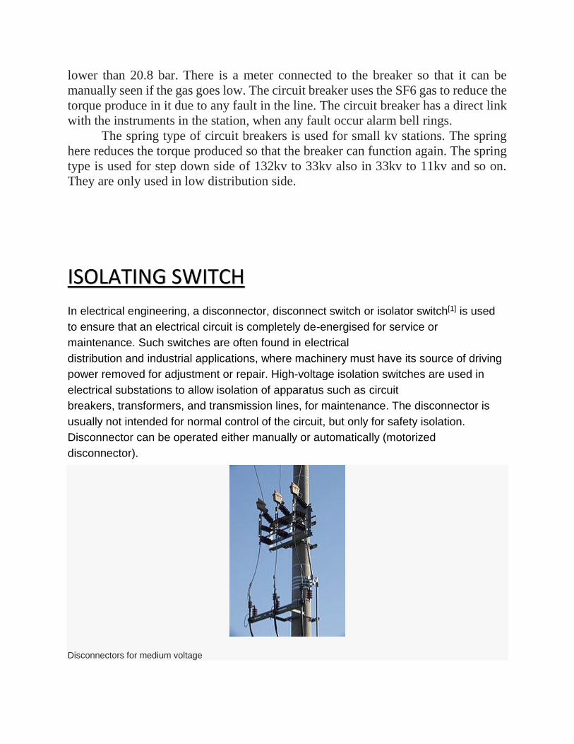
ISOLATING SWITCH
In electrical engineering, a disconnector, disconnect switch or isolator switch[1] is used
to ensure that an electrical circuit is completely de-energised for service or
maintenance. Such switches are often found in electrical
distribution and industrial applications, where machinery must have its source of driving
power removed for adjustment or repair. High-voltage isolation switches are used in
electrical substations to allow isolation of apparatus such as circuit
breakers, transformers, and transmission lines, for maintenance. The disconnector is
usually not intended for normal control of the circuit, but only for safety isolation.
Disconnector can be operated either manually or automatically (motorized
disconnector).
Disconnectors for medium voltage
Unlike load break switches and circuit breakers, disconnectors lack a mechanism for
suppression of electric arc, which occurs when conductors carrying high currents are
electrically interrupted. Thus, they are off-load devices, intended to be opened only after
current has been interrupted by some other control device. Safety regulations of the
utility must prevent any attempt to open the disconnector while it supplies a circuit.
Standards in some countries for safety may require either local motor isolators or
lockable overloads (which can be padlocked).
Disconnectors have provisions for a padlock so that inadvertent operation is not
possible (lockout-tagout). In high-voltage or complex systems, these padlocks may be
part of a trapped-key interlock system to ensure proper sequence of operation. In some
designs, the isolator switch has the additional ability to earth the isolated circuit thereby
providing additional safety.
BY- SHUVAM PATHANIA
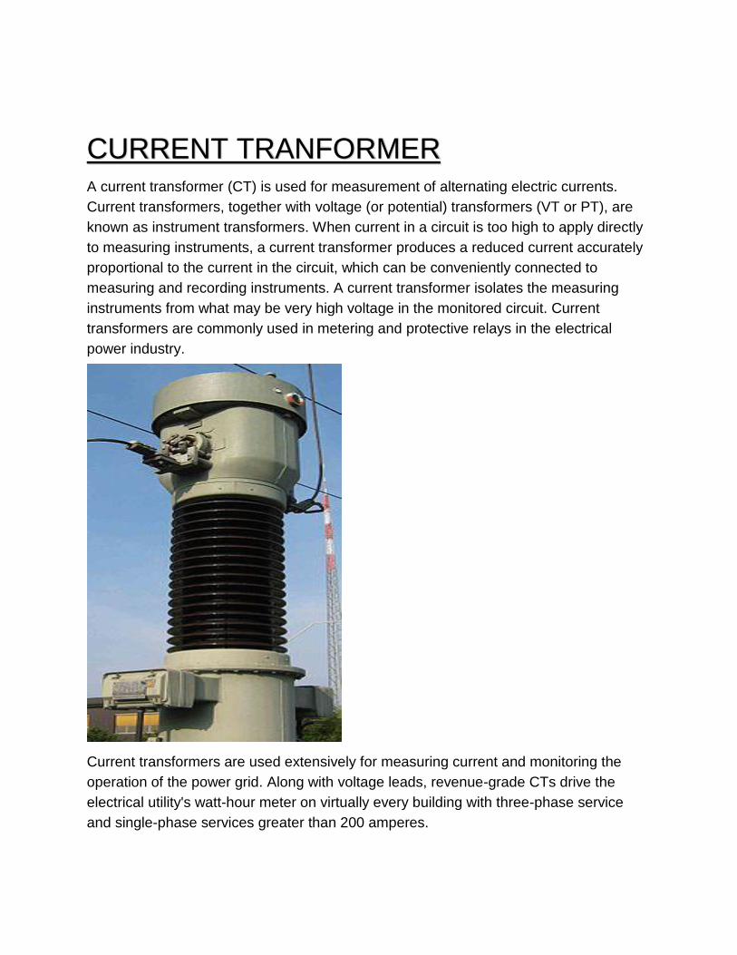
CURRENT TRANFORMER A current transformer (CT) is used for measurement of alternating electric currents.
Current transformers, together with voltage (or potential) transformers (VT or PT), are
known as instrument transformers. When current in a circuit is too high to apply directly
to measuring instruments, a current transformer produces a reduced current accurately
proportional to the current in the circuit, which can be conveniently connected to
measuring and recording instruments. A current transformer isolates the measuring
instruments from what may be very high voltage in the monitored circuit. Current
transformers are commonly used in metering and protective relays in the electrical
power industry.
Current transformers are used extensively for measuring current and monitoring the
operation of the power grid. Along with voltage leads, revenue-grade CTs drive the
electrical utility's watt-hour meter on virtually every building with three-phase service
and single-phase services greater than 200 amperes.
The CT is typically described by its current ratio from primary to secondary. Often,
multiple CTs are installed as a "stack" for various uses. For example, protection devices
and revenue metering may use separate CTs to provide isolation between metering and
protection circuits, and allows current transformers with different characteristics
(accuracy, overload performance) to be used for the devices.
The primary circuit is largely unaffected by the insertion of the CT. The rated secondary
current is commonly standardized at 1 or 5 amperes. For example, a 4000:5 CT
secondary winding will supply an output current of 5 amperes when the primary winding
current is 4000 amperes. The secondary winding can be single or multi-ratio, with five
taps being common for multi-ratio CTs.
The load, or burden, of the CT should be a low resistance. If the voltage time integral
area is higher than the core's design rating, the core goes into saturation toward the end
of each cycle, distorting the waveform and affecting accuracy.
POTENTIAL TRANSFORMER Potential transformers (PT) (also called voltage transformers (VT)) are a
parallel connected type of instrument transformer. They are designed to
present negligible load to the supply being measured and have an accurate
voltage ratio and phase relationship to enable accurate secondary
connected metering.
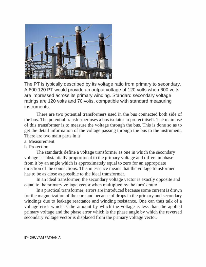
The PT is typically described by its voltage ratio from primary to secondary.
A 600:120 PT would provide an output voltage of 120 volts when 600 volts
are impressed across its primary winding. Standard secondary voltage
ratings are 120 volts and 70 volts, compatible with standard measuring
instruments.
There are two potential transformers used in the bus connected both side of
the bus. The potential transformer uses a bus isolator to protect itself. The main use
of this transformer is to measure the voltage through the bus. This is done so as to
get the detail information of the voltage passing through the bus to the instrument.
There are two main parts in it a. Measurement b. Protection
The standards define a voltage transformer as one in which the secondary
voltage is substantially proportional to the primary voltage and differs in phase
from it by an angle which is approximately equal to zero for an appropriate
direction of the connections. This in essence means that the voltage transformer
has to be as close as possible to the ideal transformer. In an ideal transformer, the secondary voltage vector is exactly opposite and
equal to the primary voltage vector when multiplied by the turn’s ratio. In a practical transformer, errors are introduced because some current is drawn
for the magnetization of the core and because of drops in the primary and secondary
windings due to leakage reactance and winding resistance. One can thus talk of a
voltage error which is the amount by which the voltage is less than the applied
primary voltage and the phase error which is the phase angle by which the reversed
secondary voltage vector is displaced from the primary voltage vector.
BY- SHUVAM PATHANIA

FUNCTIONS OF THE ASSOCIATED
SYSTEM IN A SUBSTATION
Sr
no. System Function
1. Substation Earthing system
- Earth mat
- Earthing spikes
- Earthing risers
To provide an earth mat for connecting neutral points, equipment body, support structures to earth. For safety of personnel and for enabling earth fault protection. To provide the path for discharging the earth currents from neutrals, faults, Surge Arresters, overheads shielding wires etc. with safe step-potential and touch potential.
2. Overhead earth wire shielding or Lightning masts. To protect the outdoor substation equipment from lightning strokes.
3. Illumination system (lighting)
- for switchyard
- buildings
- roads etc.
To provide proper illumination to substation yard.
4. Protection system
- protection relay
panels
- control cables
- circuit breakers
- CTs, VTs etc.
To provide alarm or automatic tripping of faulty part from healthy part and also to minimize damage to faulty equipment and associated system.
5. Control cable For Protective circuits, control circuits, metering circuits, communication circuits
6. Power cable To provide supply path to various auxiliary equipment and machines.
7. PLCC system
power line carrier communication system
For communication, telemetry, tele-control, power line carrier protection etc.
8. Telephone, telex, microwave, OPF For internal and external communication
An Overview of the 220/132/33 KV Grid Sub
Station HPSEBL Jassure
Brief about Project
This project is made to overcome the electricity crises and to meet the power
demand of Jassure, Kandrori, Dehra, Chamba and its neighboring regions. As this
area is under its development stage, there is a huge demand of the power supply,
thus this substation was installed.
This substation got installed on September 1985.
This project is fed by three feeders namely,
1) Pong HEP (BBMB)
2) RSD HEP (PSPCL)
3) Baira Suil HEP (NHPC)
Initially, 1no. 220KV/132KV, 40/50 MVA transformer bank and 220KV/33KV,
25/31.5 MVA power transformer, 2 no. 220KV feeder bayss and 6 no. 33KV
feeder bays were commissioned .
Later on, as per the requirement and demand of the region, development of the
substation continued, as 220/ 132KV, 40/50 MVA power transformer bank was
upgraded to 150MVA capacity in 1998.
01 No. 220KV feeder Bay (220 KV RSD-Jassure) was also commissioned in June
2001.
A 3 phase 220/132KV 50/ 63MVA power transformer was also added in March
2014.
Presently, the transformers installed in the substation are capable of delivering the
power of 276 MVA.
The supply is step downed by the transformers to 132KV, 33KV and 11KV and is
further step downed by the transformers connected in their respective bus bars and
is fed to its regions by its 21 outgoing feeder lines.
BY- SHUVAM PATHANIA
Based on design configuration, this project is air insulated electrical power
substation.
In Air Insulated Power Substations busbars and connectors are visible. In this
Power Substations Circuit Breakers and Isolators, Transformers, Current
Transformers, Potential Transformers etc are installed in the outdoor. Bus bars are
supported on the post Insulators or Strain Insulators. Substations have galvanized
Steel Structures for Supporting the equipment, insulators and incoming and
outgoing lines. Clearances are the primary criteria for these substations and occupy
a large area for installation.
BY- SHUVAM PATHANIA
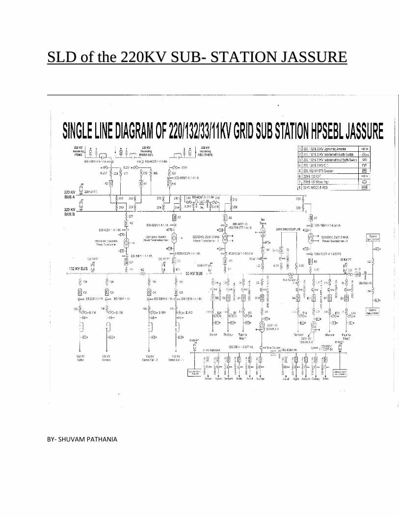
SLD of the 220KV SUB- STATION JASSURE
BY- SHUVAM PATHANIA
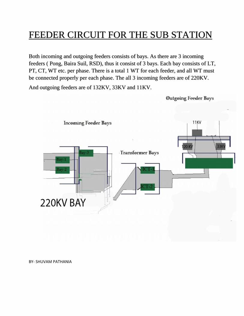
FEEDER CIRCUIT FOR THE SUB STATION
Both incoming and outgoing feeders consists of bays. As there are 3 incoming
feeders ( Pong, Baira Suil, RSD), thus it consist of 3 bays. Each bay consists of LT,
PT, CT, WT etc. per phase. There is a total 1 WT for each feeder, and all WT must
be connected properly per each phase. The all 3 incoming feeders are of 220KV.
And outgoing feeders are of 132KV, 33KV and 11KV.
BY- SHUVAM PATHANIA
SITE SELECTION FOR THE JASUURE SUB
STATION Main points considered for the selection of site for the Jassure Sub station are :
1) The site is easily approachable by highways and railways.
2) The selected site has scope for future expansion.
3) The selected site is away from the residential areas, thus permits safe
approach of the EHV lines.
4) Geographically, the selected site is in the middle of its distributive areas.
5) The selected site is slightly inclined, thus solves water logging problem
during rainy season.
BY- SHUVAM PATHANIA
CONCLUSION Transmission and distribution stations exists at various scales throughout a
power system. In general, they represent an interface between different
levels or sections of the power systems, with the capability to switch or
reconfigure the connections among various transmission and distribution
lines. The major stations include a control room from which operations are
coordinated. Smaller distribution sub stations follow same principle of
receiving power at higher level on one side and sending out a number of
distribution feeders at lower voltage on the other, but they serve a more
limited local area and are generally unstaffed. The central component of the
sub station is the transformer, as it provides the effective in enterface
between the high and low voltages. Other crucial components are circuit
breakers and switches. Breakers serve as protective devices that open
automatically in the event of a fault, that is, when a protective relay indicates
excessive current due to some abnormal condition. Switches are control
devices that can be opened or closed deliberately to establish or break a
connection. An important difference between circuit breakers and switches
is that breakers are designed to interrupt abnormally high currents , whereas
regular switches are designed to be operable under normal conditions.
Breakers are placed on both the high and low voltages side of the
transformer.
BY- SHUVAM PATHANIA