Report of Investigation Fatal Underground Coal … of Investigation Fatal Underground Coal Mine Fire...
118
Report of Investigation Fatal Underground Coal Mine Fire ________________________________________________________________________ U.S. Department of Labor Mine Safety and Health Administration 2007 Aracoma Alma Mine #1 Aracoma Coal Company, Inc. Stollings, Logan County, West Virginia I.D. No. 46-08801 January 19, 2006
Transcript of Report of Investigation Fatal Underground Coal … of Investigation Fatal Underground Coal Mine Fire...

Report of Investigation Fatal Underground Coal Mine Fire
________________________________________________________________________ U.S. Department of Labor Mine Safety and Health Administration 2007
Aracoma Alma Mine #1 Aracoma Coal Company, Inc.
Stollings, Logan County, West Virginia I.D. No. 46-08801
January 19, 2006

UNITED STATES DEPARTMENT OF LABOR
MINE SAFETY AND HEALTH ADMINISTRATION COAL MINE SAFETY AND HEALTH
REPORT OF INVESTIGATION
Fatal Underground Coal Mine Fire
January 19, 2006
Aracoma Alma Mine #1 Aracoma Coal Company, Inc.
Stollings, Logan County, West Virginia I.D. No. 46-08801
by
Kenneth A. Murray
District Manager, District 6, Pikeville, KY
Charles W. Pogue Roof Control Specialist, District 2, Ruff Creek, PA
Ronald W. Stahlhut
Electrical Supervisor, District 8, Vincennes, IN
Michael G. Finnie Supervisory Special Investigator, District 10, Madisonville, KY
Arlie A. Webb
Supervisory Special Investigator/Staff Assistant, District 6, Pikeville, KY
Anthony L. Burke Coal Mine Safety and Health Inspector, District 6, Whitesburg, KY
Dennis A. Beiter
Supervisory Mining Engineer, Technical Support, Triadelphia, WV
William J. Francart, P.E. Mining Engineer, Technical Support, Pittsburgh, PA
Derrick M. Tjernlund
Senior Fire Protection Engineer, Technical Support, Triadelphia, WV
Jeffrey N. Waggett Civil Engineer, Technical Support, Pittsburgh, PA
Originating Office Mine Safety and Health Administration
Office of the Administrator Coal Mine Safety and Health
1100 Wilson Boulevard Arlington, Virginia 22209
Kevin G. Stricklin, Acting Administrator

TABLE OF CONTENTS OVERVIEW................................................................................................................................... 1 GENERAL INFORMATION ...................................................................................................... 2 DESCRIPTION OF THE ACCIDENT ....................................................................................... 4
Activities Prior to the Accident.............................................................................................. 4 Production Crews .................................................................................................................... 5 Outby Belt Examiners.............................................................................................................. 5 The Fire ...................................................................................................................................... 7 The Order to Evacuate............................................................................................................. 8 Evacuation of 2 Section ........................................................................................................... 9 Longwall Section Activities During the Fire...................................................................... 13 Initial Rescue and Firefighting Attempts ........................................................................... 14
MINE RESCUE AND RECOVERY OPERATIONS............................................................... 16 INVESTIGATION OF THE ACCIDENT ................................................................................ 21 DISCUSSION.............................................................................................................................. 21
Training ................................................................................................................................... 22 Roof Control Plan................................................................................................................... 23 Mine Emergency Evacuation and Firefighting Program of Instruction ........................ 24 Self-Contained Self Rescuers ................................................................................................ 25
SCSR Training, Testing and Examination Requirements............................................. 26 Required SCSR Training.................................................................................................. 26 Required SCSR Examinations and Tests ......................................................................... 27
Investigative Examination and Testing of Recovered SCSRs...................................... 28 Mine Ventilation Plan............................................................................................................ 29 Mine Ventilation..................................................................................................................... 31
Development Sections ....................................................................................................... 32 Longwall Section and Bleeder System............................................................................ 33 Methane Liberation............................................................................................................ 34 Ventilation System Maintenance and Stability.............................................................. 34 Changes in Ventilation...................................................................................................... 35
Belt Air Regulations............................................................................................................... 40 Atmospheric Monitoring System ........................................................................................ 41
AMS Event Log .................................................................................................................. 44 AMS Sensor Calibration Records..................................................................................... 44 Laboratory Testing............................................................................................................. 45 AMS Installation and Maintenance Related Deficiencies ............................................ 46 Alert, Alarm, and Malfunction Signal Response Deficiencies .................................... 48 AMS Response on January 19, 2006 ................................................................................ 49
Electrical System .................................................................................................................... 52 Electrical Examinations and Tests ................................................................................... 53 Inspection of the 9 Headgate Longwall Belt Drive Electrical Components .............. 53 Water Sprinkler System for the 9 Headgate Longwall Belt ......................................... 54
Escapeways, Escapeway Maps and Drills.......................................................................... 55

Underground Escapeways ............................................................................................... 56 Main Escapeways ............................................................................................................. 57 Escapeways from 2 Section ............................................................................................... 57 9 Headgate Longwall Section Escapeways ....................................................................... 58
Escapeway Drills................................................................................................................ 59 Mine Examinations ................................................................................................................ 60
Preshift and On-shift Examinations ................................................................................ 62 9 Headgate Longwall Belt ................................................................................................. 62 Dual Switch House Installation Project ........................................................................... 64 No. 7 Belt and Underground Electrical Installations for the 9 Headgate Longwall Belt Drive and Takeup Storage Unit ....................................................................................... 65 No. 7 Belt Structure Extension Project ............................................................................ 66 Roadway from NEM to 2 Section..................................................................................... 67
Weekly Examinations........................................................................................................ 68 Intake Air Courses and Primary Escapeway for 2 Section............................................... 69 No. 7 Belt Air Course ....................................................................................................... 70 Intake Air Course and Primary Escapeway for 9 Headgate Longwall Section ................ 71 Alternate Escapeways for 2 Section and 9 Headgate Longwall Section........................... 71 9 Tailgate Air Course........................................................................................................ 72
Fire Protection ........................................................................................................................ 72 Water Supply System ........................................................................................................ 72 Freshwater Supply Tank................................................................................................... 73 Underground Freshwater Pumps.................................................................................... 75 Water Supply and Mine Elevations................................................................................. 76 Valved Firehose Outlets.................................................................................................... 76 Firehoses and Connections ............................................................................................... 76 Annual Functional Tests ................................................................................................... 77 Longwall Belt Fire Protection........................................................................................... 77 Conveyor Belt Flame Resistance Testing........................................................................ 78
Area of Fire Origin and Flame Propagation ...................................................................... 79 Observations ....................................................................................................................... 80 Belt Entry Slope and Its Effect on Flame Propagation.................................................. 81 Point of Fire Origin ............................................................................................................ 82 Continuity and Availability of Combustible Materials in the Area of Fire Origin .. 82 Fire Spread Inby the Area of Origin................................................................................ 82
Potential Ignition Sources ..................................................................................................... 83 Sources of Ignition ............................................................................................................. 83 Belt Material Response-to-Fire Considerations ............................................................. 86 Likely Initial Fuel Source .................................................................................................. 87
Additional Information......................................................................................................... 87 Previous Belt Entry Fires and Other Incidents .............................................................. 87
8 Headgate Longwall Belt Takeup Storage Unit Fire....................................................... 87 October 8, 2005, AMS Response ...................................................................................... 88 December 23, 2005, Fire ................................................................................................... 89

December 29, 2005, Fire ................................................................................................... 90 Corporate Communications ................................................................................................. 92
ROOT CAUSE ANALYSIS ....................................................................................................... 92 CONCLUSION........................................................................................................................... 97 ENFORCEMENT ACTIONS .................................................................................................... 98
TABLES Table 1 - Incident Rates for 2005 ................................................................................................ 4 Table 2 - Information on SCSRs for Afternoon Shift 2 Section Personnel ......................... 27 Table 3 - Results of Laboratory Tests on SCSRs .................................................................... 29 Table 4 - Abridged AMS Event Log from January 19, 2006................................................. 50
FIGURES
Figure 1. Evidence of belt misalignment. ................................................................................ 7 Figure 2. Seating arrangement of miners on 2 Section diesel mantrip.............................. 10 Figure 3. Absence of critical ventilation control. .................................................................. 37 Figure 4. Area inby No. 7 Belt tail pulley. ............................................................................. 38 Figure 5. Critical ventilation control removed prior to fire. ............................................... 38 Figure 6. Location where belt structure was installed after removal of a stopping........ 39 Figure 7. Additional critical ventilation control removed prior to fire. ............................ 40 Figure 8. Former location of stopping at the electrical installation. .................................. 40 Figure 9. Carbon monoxide sensor......................................................................................... 41 Figure 10. Remote alarm unit in headgate area on longwall section. ............................... 42 Figure 11. AMS in dispatcher’s office located in Box Cut on surface................................ 42 Figure 12. Relative CO Sensor Locations on January 19, 2006. .......................................... 51 Figure 13. Grooves cut into the rear frame assembly. ......................................................... 63 Figure 14. 4-inch water valve (found in “off” position) ...................................................... 75
APPENDICES
Appendix A Mine Map
Active Underground Areas Appendix B Management Structure Appendix C Mine Map
Area Surrounding 9 Headgate Longwall Section and 2 Section Appendix D Mine Map and Drawing
9 Headgate Longwall Belt Takeup Storage Unit - Basic Components and Operation Description
Appendix E Mine Map Affected Area of Mine, Portion of North East Mains
Appendix F Mine Map Affected Area of Mine, Detail of Area Surrounding 2 Section Mantrip

APPENDICES (Continued) Appendix G Timeline Events that Occurred at Aracoma Alma Mine #1 on January 19, 2006 Appendix H List of Mine Rescue Teams and Team Members Appendix I Victim Data Sheets Appendix J List of Investigation Participants Appendix K Mine Map
Mine Ventilation Map 1 of 2 Appendix L Mine Map
Mine Ventilation Map 2 of 2 Appendix M Mine Map
Image of Mine Map Identified by Operator Representatives Maintained as the Map 30 CFR Section 75.1202-1 Required to be Kept up-to-date with Temporary Notations
Appendix N Mine Map Atmospheric Monitoring System Carbon Monoxide Sensor Locations
Appendix O Mine Map Electrical and Freshwater Supply Systems Schematic
Appendix P Mine Map Electrical and Freshwater Supply Systems Schematic Detail Views
Appendix Q Mine Map Escapeways for 2 Section and 9 Headgate Longwall Section
Appendix R Mine Map Primary Escapeways for 2 Section and 9 Headgate Longwall Section to Box Cut
Appendix S Mine Map Image of 2 Section Escapeway Map
Appendix T Mine Map Image of 9 Headgate Longwall Section Escapeway Map
Appendix U Graph Hydraulic Elevation Profile
Appendix V Mine Map 9 Headgate Longwall Belt Drive Area Fire Protection
Appendix W Belt Flame Test Results Appendix X Mine Map
Extent of Fire Spread Appendix Y Spontaneous Combustion Test Results on Coal Samples Appendix Z Locations and Responses of CO Sensors for Events on October 8, 2005,
December 23, 2005, and December 29, 2005 Appendix AA Corporate Communications Memos


1
OVERVIEW At approximately 5:14 p.m. on January 19, 2006, a fire occurred at the 9 Headgate longwall belt takeup storage unit of the Aracoma Alma Mine #1, resulting in the deaths of two miners. Twenty-nine underground miners were working on this shift. Initial attempts to extinguish the fire failed, and observations at the scene indicated that smoke from the fire was traveling further into the mine via the 2 Section intake air course. Miners in affected areas were neither immediately notified nor withdrawn following the initial carbon monoxide (CO) alarm signal from the Atmospheric Monitoring System (AMS). After the 2 Section foreman was informed that smoke from the fire was traveling toward the section in the intake air course, he assembled the other 11 miners working on the section and began an evacuation. The foreman told the miners if they encountered smoke and were unable to travel all the way out the roadway, they would move into the adjacent North East Mains (NEM) belt entry through a personnel door.
The 2 Section crew boarded a rubber-tired diesel mantrip and began traveling out the roadway in the intake air course. After traveling approximately 1,800 feet, the crew smelled smoke. The crew continued traveling in the mantrip for approximately 400 feet before they encountered light smoke. Following the roadway, the mantrip turned right and traveled through a crosscut into an adjacent intake entry, where the crew encountered dense, black smoke that prevented further travel by mantrip. The crew immediately exited the mantrip and began traveling outby on foot toward a personnel door. The miners traveled from 100 to 225 feet in smoke before donning their Self Contained Self Rescuers (SCSRs). After donning their SCSRs, groups of miners held onto each other in the dense smoke, feeling their way along the coal rib as they moved outby. Ten of the miners found the personnel door and entered the clear air in the belt entry. Once in the smoke-free air, the miners discovered that Don Bragg and Ellery Hatfield were missing. Three miners returned to the smoke-filled intake air course to search for the missing men, but were unable to find them and re-entered the belt entry. The ten miners continued the evacuation via the alternate escapeway to a safe area outby the fire. Miners from 2 Section and the longwall section assisted in attempts to reduce the air flow to the fire before being evacuated to the surface. Mine management personnel traveled underground in an attempt to locate the missing miners and extinguish the fire, but were unsuccessful. Meanwhile, mine rescue teams were called to the mine to continue the rescue and firefighting efforts. Smoke and heat hampered search and rescue activities as the fire continued burning. On January 21, the bodies of the two missing miners were discovered approximately 575 feet apart in NEM, and transported to the surface. The fire was fully extinguished on January 24.

2
The fire occurred as a result of frictional heating when the longwall belt became misaligned in the 9 Headgate longwall belt takeup storage unit. Frictional heating ignited accumulations of combustible materials which served as a readily ignitable fuel. This further contributed to the ignition of the belt and to the intensity and extent of the mine fire. The required fire suppression system was not installed and there was no water available in the area to fight the fire. Airflow carried the smoke from the fire to the No. 7 Belt entry and then into the primary escapeway for 2 Section because stoppings that were required to maintain separation between the belt entry and the primary escapeway for 2 Section had previously been removed. Examinations of the mine were inadequate and failed to identify the lack of separation between the primary escapeway and belt air course. Examiners were not always provided with an anemometer or other means to measure air velocity and airflow direction during examinations of the belt entries. Not all examiners were provided adequate gas detection equipment on all shifts. In addition, examinations of safety systems failed to identify deficiencies which contributed to the severity and extent of the mine fire. Mine management did not immediately withdraw miners from the affected areas (2 Section and the longwall section) when the AMS generated an alarm signal. Approximately 28 minutes elapsed between the time of the first CO alarm and the time evacuation of the miners on 2 Section was initiated. Two miners from 2 Section became separated from the other miners during the evacuation and perished. The remaining twenty-seven miners working underground escaped safely. As a result of the investigation, MSHA issued 25 citations and orders for violations which contributed to the cause or severity of the accident. Of these, 21 were the result of reckless disregard on the part of the mine operator. Five of the citations and orders were related to the belt air rule. Had the mine operator been in compliance with the belt air rule, the fire would not have resulted in the two fatalities. These contributory violations are listed at the end of this report in the “Enforcement Actions” section.
GENERAL INFORMATION Aracoma Coal Company, Inc.’s Aracoma Alma Mine #1 is an underground coal mine located on Bandmill Hollow Road, approximately 1.5 miles off Route 17 North, near Stollings in Logan County, West Virginia. Production at the mine began on October 1, 1999. The mine has been owned and operated by Massey Energy Company throughout its history. The active underground areas of the mine are shown in Appendix A. Principal officers of Aracoma Coal Company, Inc. included Dwayne B. Francisco, President; Eddie Lester, Vice President of Operations; Gary Goff, General Manager; Lawrence Lester, Superintendent; and Charles Conn, Safety Director. Information provided by the mine operator relative to the corporate management structure, as it existed at the time of the fire, is shown in Appendix B.

3
At the time of the accident, coal was extracted from the Alma Coal Seam which ranged from 30 to 60 inches in thickness throughout the mine, with an average cover of 800 feet and a maximum cover of 1,200 feet. The immediate roof strata consisted of up to 12 inches of gray sandy shale, and 20 to 25 feet of solid sandstone. Coal was produced on a longwall section and two continuous mining machine sections. Coal was transported from the working sections to the surface via a series of belt conveyors. Longwall panels at this mine varied from 3,600 to 6,000 feet in length with faces approximately 1,000 feet wide. Production on the longwall section, located in 9 Headgate, began in September, 2005. The 9 Headgate longwall section had mined approximately 3,500 feet. Approximately 1,575 feet remained in the panel. Longwall section equipment included a shearer and related components, one scoop, and one shield hauler. The roof along the longwall face was supported by longwall shield units. The continuous mining machine section designated as 2 Section was developing four entries in 11 Headgate off NEM. The 2 Section Nos. 1 and 4 Entries were the section return air courses, and Nos. 2 and 3 Entries were the section intake air courses. The No. 2 Entry was also the belt haulage entry. Development equipment on 2 Section consisted of two continuous mining machines, three shuttle cars, two roof bolting machines, three scoops, and a feeder. The continuous mining machine section designated as 3 Section developed the 3 West Mains off North West Mains. Nos. 1 and 7 Entries of this seven entry development were the section return air courses. Nos. 2 and 3 Entries were section intake air courses. The Nos. 5 and 6 Entries were common with the belt haulage entry, which was located in the No. 4 Entry. Development equipment on 3 Section included two continuous mining machines, three shuttle cars, two roof bolting machines, three scoops, and a feeder. During the third and fourth quarters of Calendar Year (CY) 2005, coal production at the mine was reported as 352,242 and 541,413 tons, respectively. Total employment for these two quarters was reported as 171 and 178 persons, respectively. At the time of the accident, the mine employee roster listed 173 employees. The miners were not represented by a labor organization. Table 1 shows the Non-Fatal Days Lost (NFDL) and overall incidence rates for the Aracoma Alma Mine #1, along with comparable national rates for all underground coal mines. The overall incidence rate is a compilation of the Fatal, NFDL, and No Days Lost incidence rates. Incidence Rates are the number of incidents that occur per 200,000 hours of employee exposure. The table shows the rates for 2005. The accident occurred during the 1st Quarter of 2006.

4
Table 1. Incidence Rates for 2005
Incidence Rate Aracoma Alma Mine #1 National Average
NFDL 7.20 3.51 Overall 10.59 5.10
A Safety and Health Inspection by the Mine Safety and Health Administration (MSHA) had begun on January 3, 2006, and was in progress at the time of the accident. The previous Safety and Health Inspection had been completed on December 23, 2005. The last underground MSHA inspection activity at the Aracoma Alma Mine #1 prior to the accident was on January 13, 2006.
DESCRIPTION OF THE ACCIDENT
Activities Prior to the Accident On Thursday, January 19, 2006, at approximately 2:30 p.m., underground miners on the afternoon shift traveled to their assigned work locations. Production crews traveled to the longwall section and 2 Section via rubber-tired diesel mantrips. The location of 2 Section and 9 Headgate longwall section are shown in Appendix C. The 2 Section production crew consisted of Michael Plumley, Foreman; Roof Bolting Machine Operators Elmer Mayhorn, Randall Crouse, Ellery Hatfield, and Don Bragg; Shuttle Car Operators Joe Hunt, Pat Kinser, and Gary Baisden; Continuous Mining Machine Operators Steve Hensley and Billy Mayhorn; Electrician Harold Shull; and Scoop Operator Thomas Vanover. The longwall section production crew consisted of Dave Runyon, Foreman; Shearer Operator Dave Sanders; Shield Operator Arnold Lane; Headgate Operator Gary Richardson; Utility John Brown; Electrician Joey Duty; and Maintenance Foreman Jamie Adkins. Other persons on the afternoon shift were assigned to duties in the belt entries, roadways, and other outby areas of the mine. Those persons were Belt Walker Bryan Cabell; Production Foreman Patrick Callaway; Utility Underground Brandon Conley; Electrician Bryson Ellis; Road Grader Operator Raymond Grimmett; afternoon shift Chief Electrician Billy Hall; Roof Bolting Machine Operators Brandon Lusk and Joshua Noe; Outby man Jonah Rose. The afternoon shift Mine Foreman was Fred Horton. In this capacity, Horton was designated by the Mine Emergency Evacuation and Firefighting Program of Instruction as the “Responsible Person” to take charge during mine emergencies involving fires, explosions, or inundations. In all, there were 29 persons assigned to work underground on the afternoon shift.

5
Production Crews The 2 Section crew arrived at the 9 Headgate longwall belt drive at approximately 3:30 p.m., and traveled through the outby pair of equipment doors in that location. The equipment doors were opened by Carl White, Belt Examiner, who was working at the 9 Headgate longwall belt drive area on day shift. The crew traveled under the longwall belt between the belt drive and takeup storage unit, through the inby pair of equipment doors, and continued on to 2 Section. Sworn statements indicate the crew did not see, smell, or notice any unusual conditions as they passed through the equipment doors. The afternoon shift production crew arrived on 2 Section at approximately 3:48 p.m. and met with the day shift production crew. They discussed pending changes in the work schedule at the mine while waiting for dust from rock dusting operations in the face area to clear. The day shift production crew left 2 Section shortly thereafter. Billy Mayhorn and Gary Baisden were assigned to build cribs in the 2 Section right return air course outby the section. The remainder of the 2 Section crew proceeded to their work stations in the face area. Production began and continued until the time of the accident. The longwall crew arrived on the longwall section at approximately 3:55 p.m. and relieved the day shift crew. The longwall belt had been shut off while cutter bits were replaced on the shearer and longwall belt structure near the tail was removed. Production resumed after the longwall belt was restarted at approximately 4:20 p.m.
Outby Belt Examiners Cabell was assigned to examine belts and work at the 9 Headgate longwall belt drive area. After entering the mine via the Box Cut portal, he walked along Nos. 4, 5, 6 Belts, and along the No. 7 Belt, up to the longwall belt drive. On his way he shoveled some coal accumulations. He stopped to answer a call on the mine phone from White who was at the 9 Headgate longwall belt drive area. White told Cabell he was leaving the longwall belt drive area because production on the longwall section had ceased for routine maintenance of the face equipment. Since there would be no production for the rest of his shift, White told Cabell he intended to walk to the longwall headgate area so he could ride out with the section crew at the end of the shift. White informed Cabell of the conditions he had encountered on the day shift in the longwall belt drive and takeup storage unit area, including electrical problems with the winch motor, rubbing of the longwall belt that would require realignment, and a haze he had observed. White asked Cabell to come to the longwall belt drive area so that he could leave. White left the drive area sometime after 3:30 p.m. and did not see any hazardous conditions as he passed the belt takeup storage unit. The longwall belt was off at the time White passed the takeup storage unit because belt structure was being removed to accommodate the retreating longwall face.
6
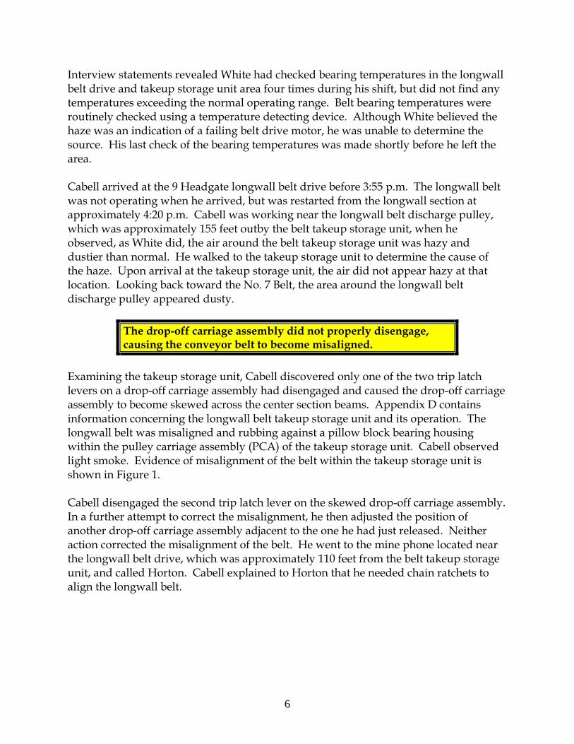
Interview statements revealed White had checked bearing temperatures in the longwall belt drive and takeup storage unit area four times during his shift, but did not find any temperatures exceeding the normal operating range. Belt bearing temperatures were routinely checked using a temperature detecting device. Although White believed the haze was an indication of a failing belt drive motor, he was unable to determine the source. His last check of the bearing temperatures was made shortly before he left the area. Cabell arrived at the 9 Headgate longwall belt drive before 3:55 p.m. The longwall belt was not operating when he arrived, but was restarted from the longwall section at approximately 4:20 p.m. Cabell was working near the longwall belt discharge pulley, which was approximately 155 feet outby the belt takeup storage unit, when he observed, as White did, the air around the belt takeup storage unit was hazy and dustier than normal. He walked to the takeup storage unit to determine the cause of the haze. Upon arrival at the takeup storage unit, the air did not appear hazy at that location. Looking back toward the No. 7 Belt, the area around the longwall belt discharge pulley appeared dusty.
The drop-off carriage assembly did not properly disengage, causing the conveyor belt to become misaligned.
Examining the takeup storage unit, Cabell discovered only one of the two trip latch levers on a drop-off carriage assembly had disengaged and caused the drop-off carriage assembly to become skewed across the center section beams. Appendix D contains information concerning the longwall belt takeup storage unit and its operation. The longwall belt was misaligned and rubbing against a pillow block bearing housing within the pulley carriage assembly (PCA) of the takeup storage unit. Cabell observed light smoke. Evidence of misalignment of the belt within the takeup storage unit is shown in Figure 1. Cabell disengaged the second trip latch lever on the skewed drop-off carriage assembly. In a further attempt to correct the misalignment, he then adjusted the position of another drop-off carriage assembly adjacent to the one he had just released. Neither action corrected the misalignment of the belt. He went to the mine phone located near the longwall belt drive, which was approximately 110 feet from the belt takeup storage unit, and called Horton. Cabell explained to Horton that he needed chain ratchets to align the longwall belt.

7
Figure 1. Evidence of belt misalignment.
The Fire Cabell returned to the belt takeup storage unit and noticed the intensity of the smoke in the air was increasing. Cabell stopped the longwall belt at approximately 5:05 p.m. to avoid damaging the belt. He went back to the phone near the drive and called Horton again to see when help would arrive. When Horton did not immediately answer, Gary Brown, Dispatcher/AMS Operator, answered the phone. Horton, who was at the North West Mains No. 1 “4-Way,” joined the conversation. While on the phone, Cabell looked toward the belt takeup storage unit and observed smoke and glowing embers under the left side of the belt where the belt had been rubbing. Cabell noticed the intensity of the smoke was increasing, and told Horton a fire existed at the belt takeup storage unit. Horton told Cabell that Callaway was on his way into the area, and to keep him there to assist.
When the first CO alarm was indicated at 5:14 p.m., the AMS operator did not notify the appropriate personnel.
AMS CO Sensor 82 indicated alert and alarm levels of CO at approximately 5:14 p.m., during the phone conversation between Cabell and Horton. Brown went to the AMS computer and acknowledged the alarm. Brown did not notify either person of the alarm signal because Cabell was already at the scene and had reported seeing smoke to Horton. Under § 75.1501, Horton, in the capacity of Mine Foreman on the afternoon shift, had been designated by the mine operator as a responsible person to take charge during a mine emergency such as a fire. At 5:16 p.m., CO Sensor 81 also indicated alert and alarm levels of CO.

8
The phone conversation between Cabell and Horton was ongoing when Callaway and Rose arrived at the longwall drive equipment doors. Callaway and Rose both observed smoke as they traveled through the doors and entered the area. After exiting the mantrip, Rose observed light smoke traveling toward the No. 7 Belt. Then Rose saw flames along the left side of the takeup storage unit, and observed the coal rib was also burning. Rose did not know if Cabell could see the flames from his location.
Firehose couplings were not compatible with fire valve outlets and there was no water in the line.
Cabell obtained a fire extinguisher from Callaway’s mantrip and discharged it, along with another nearby extinguisher, at the fire. As soon as he had depleted the extinguishers the flames returned. Rose went to retrieve additional fire extinguishers. Cabell attempted to connect a firehose, which was lying on the ground alongside the belt takeup storage unit, to a firehose outlet located within 50 feet of the fire, between the fire and the longwall belt drive. He was unable to make the connection because the threads of the firehose coupling and the threads of the firehose outlet were not compatible. When he opened the firehose outlet valve, in an attempt to direct at least some water onto the fire, he found there was no water in the line. Cabell then sent Callaway to find where the water supply had been shut off. As Rose traveled along the No. 7 Belt, he observed smoke traveling from the fire area toward the No. 7 Belt drive. Rose returned with another fire extinguisher, which was immediately discharged at the fire. The dry chemical from the three extinguishers did not extinguish the fire. Meanwhile, Callaway had reached the shut-off valve in the waterline that delivered water inby along the No. 7 Belt toward the longwall drive area, and found it partially closed. This valve was located near the No. 7 Belt discharge pulley, approximately 1,200 feet from the fire area. He heard water flow through the waterline as he fully opened the shut-off valve. He then opened a nearby firehose outlet that was downstream of the shut-off valve and confirmed water was available at that point in the waterline. Callaway then returned to the fire area. No further attempts were made to apply water onto the fire because personnel had to evacuate the fire area due to the growing intensity of the smoke.
The Order to Evacuate Cabell recognized smoke was traveling toward 2 Section. He called outside and instructed Brown to call 2 Section and initiate an evacuation. After calling 2 Section and getting no response, Brown activated the signal light on the section pager phone. Still receiving no response, he then used the AMS computer to remotely stop the NEM No. 1 Belt. Sequence switches in the belt system stopped the NEM No. 2 and No. 3 Belts at 5:39 p.m. This belt stoppage was automatically recorded on the AMS event log.

9
Evacuation of the miners on 2 Section was not initiated until approximately 28 minutes after the first CO alarm signal.
Minutes after the belt was stopped, Plumley called Brown from 2 Section to find out why the belt had stopped. Brown informed Plumley of the fire and the need to evacuate. Horton joined the conversation on the pager phone and reinforced to Plumley the order to evacuate. This was the first time 2 Section personnel were notified of the fire and the need to evacuate. The order to evacuate the miners on 2 Section was not given until approximately 28 minutes after the first CO alarm signals from the AMS occurred and were acknowledged by Brown. When Horton and Hall arrived at the 9 Headgate longwall belt drive area, Horton instructed Callaway to account for miners as they arrived from 2 Section. Horton traveled through the equipment doors and attempted to evaluate the fire but was unable to approach it due to the dense smoke. Horton and Callaway instructed Rose to go to the intake outby the equipment doors to watch for the 2 Section miners in case they were evacuating via the roadway. Rose went to the equipment doors and stayed there until the area became engulfed in dense smoke. The primary escapeway in the intake air course outby the equipment doors had also become contaminated with smoke. Rose donned his SCSR and followed the contour of the rib out of the smoke.
Evacuation of 2 Section After Brown and Horton told Plumley to evacuate 2 Section, Plumley sent personnel to bring the rest of the crew to where the mantrip was parked. Shull was standing with Plumley at the mine phone and overheard Plumley discussing the fire and the need to evacuate. Crouse and Elmer Mayhorn were bolting in the No. 1 Entry when Kinser told them about the fire. Hunt went to the No. 2 Entry where Hensley was backing the continuous mining machine out of the No. 1 Entry and told him about the need to evacuate. Hunt then went to notify Bragg and Hatfield, who were bolting roof in the No. 4 Entry. Vanover was near one of the continuous mining machines when he heard Plumley yell, telling them about the fire and the need to get out. As Vanover walked toward the mantrip, he heard the roof bolting machine still operating in the face of No. 4 Entry. He also told Bragg and Hatfield about the evacuation order.
The locations of all personnel doors along escapeways were not clearly marked.
Before boarding the mantrip, Plumley told the miners if they were unable to travel all the way out using the roadway, they would move into the adjacent NEM belt entry.

10
This belt entry was the alternate escapeway for 2 Section. Plumley instructed them to use a personnel door located along the roadway, one break outby the crosscut where several cribs had been installed on both sides of the roadway. The personnel door had been recently installed to facilitate examination of a seal in NEM, but its location was not marked. Interview statements indicated all miners on 2 Section were not familiar with the location of the personnel door. As the crew was boarding the mantrip, Hensley offered to get some rock dust to use for firefighting, but Plumley declined. After the 2 Section crew boarded the diesel mantrip, Hensley drove to the area just outby the section where Billy Mayhorn and Gary Baisden were loading crib blocks to be used to build cribs onto a scoop. While working outby the 2 Section, Billy Mayhorn thought he smelled smoke prior to the mantrip arriving to pick them up. He mentioned it to Gary Baisden, who did not smell the smoke. They continued to work until the 2 Section mantrip stopped near them. When the mantrip arrived at their work location, Hensley shut off the mantrip. He told Baisden and Mayhorn there was a fire and they were going to evacuate. As they prepared to board the mantrip, Plumley again gave instructions regarding the route they would take out of the mine. Plumley was standing on the side of the mantrip beside the compartment where Bragg was seated. Billy Mayhorn was standing on the opposite side of the mantrip from Plumley, next to the compartment where Hatfield was seated. Billy Mayhorn and Hatfield discussed the evacuation plan. After boarding the mantrip, the entire 2 Section crew continued their evacuation, traveling out the No. 5 Entry of NEM. The locations where the miners were seated in the mantrip are shown in Figure 2.
12 3 4
5 6 711
10
14
9
8
13
12
Figure 2. Seating arrangement of miners on 2 Section diesel mantrip
1. Steven Hensley 8. Thomas Vanover 2. Elmer Mayhorn 9. Unoccupied 3. Billy Mayhorn 10. Randall Crouse 4. Ellery Hatfield 11. Patrick Kinser 5. Michael Shull 12. Unoccupied 6. Don Bragg 13. Michael Plumley 7. Joseph Hunt 14. Gary Baisden

11
As the miners resumed their evacuation, at least some of them did not fully recognize the seriousness of the situation. At least one miner believed they would go to assist in extinguishing a small fire and then return to work on 2 Section. Plumley instructed the miners in the rear compartment of the mantrip that, if they were unable to continue traveling out the roadway, they would move into the adjacent NEM belt entry. After traveling approximately 1,800 feet to a location between 10 Headgate and 9 Tailgate, some of the crew on the mantrip smelled smoke. The crew continued traveling in the mantrip for approximately 400 feet before they encountered light smoke. Some miners covered their noses and mouths with their shirts to filter out the smoke. Following the roadway, the mantrip turned right and traveled through a crosscut into the adjacent intake entry and encountered dense, black smoke that prevented further travel by mantrip. Hensley was unable to see and was forced to stop the mantrip. As the crew exited the mantrip, Plumley again reminded them to go to the personnel door outby the heavily cribbed crosscut. Some of the 2 Section miners indicated they moved a few steps from the mantrip, in an outby direction, before donning their SCSRs. Others indicated they were immediately next to the mantrip when they donned their SCSRs. Some miners reported visibility was so poor they could not see more than one foot. Others estimated that visibility was 10 to 12 feet when the miners first exited the mantrip. The smoke at the mine floor was less dense, and miners knelt to begin the SCSR donning process. Several miners lost their protective goggles when the SCSRs were opened. MSHA investigators identified the locations where miners first paused to don their SCSRs. Appendices E and F show where SCSR top covers, bottom covers, and goggles were found. The SCSR top and bottom covers are removed and discarded as part of the donning process. The person to whom a specific SCSR was assigned was determined using the unique identifying numbers on the SCSR components found during the investigation and the company’s records of the persons to whom those SCSRs were assigned. Physical evidence mapped during the investigation revealed the locations where miners donned their SCSRs were different from the miners’ recollection. This evidence revealed the miners had traveled from 100 to 225 feet in smoke before donning their SCSRs. Seven miners donned their SCSRs in a group approximately 100 feet outby the mantrip. Four miners, including Hatfield, donned their SCSRs in a group approximately 170 feet outby the mantrip. The SCSR case parts for the SCSR assigned to Bragg were found approximately 220 feet outby the mantrip. Mike Shull had been seated next to Bragg on the mantrip, and as they exited Shull told Bragg to put on his SCSR. This was the last contact anyone had with Bragg. Some of the 2 Section crew members believed Bragg exited the mantrip immediately and traveled in an outby direction. In the dense smoke, it is likely other crew members

12
could not see that Bragg had stopped nearly two crosscuts outby the mantrip to don his SCSR. The top and bottom covers of Bragg’s SCSR were located near Survey Station (SS) 3228 in the area where cribs were installed. These cribs were the landmark identified by Plumley for finding the personnel door to the NEM belt entry. Bragg was found in a crosscut, near SS 3317, approximately 7 crosscuts outby the spot where he donned his SCSR. In the group of miners with Hatfield were Billy Mayhorn, Elmer Mayhorn, and Hensley. Four pairs of goggles were found along with SCSR covers. One miner had problems taking his SCSR out of the carrying pouch. He also lost his goggles and had difficulty finding the lanyard to activate the SCSR. One miner was heard saying his SCSR was not working, and another miner told him to blow into the unit to start the oxygen production. Billy Mayhorn, who was immediately next to Hatfield while donning his SCSR, assumed Hatfield had donned his rescuer. Hatfield left the group before Mayhorn completed donning his SCSR. It is not known how Hatfield became separated from the group. Hatfield’s lunch bucket was found between SS 3308 and SS 3256. Along with the lunch bucket were a hammer and a shirt with the name “Don” imprinted on the front. Hatfield was found in a crosscut that was between SS 3267 and SS 3333, one crosscut inby the 9 Headgate longwall belt drive, 11 ½ crosscuts outby the area where he donned his SCSR. The group of seven miners paused near SS 3537, one crosscut outby the mantrip, to don their SCSRs. This group included Baisden, Hunt, Crouse, Vanover, Shull, Plumley and Kinser. Three pairs of goggles were found in the area where the SCSR top and bottom covers were located. One miner stated he had problems locating the activation lanyard. He grabbed the cord and pulled it using channel locks. Another miner experienced nausea during the donning process. As they donned their SCSRs, miners began to move outby. Shull came face-to-face with Baisden, who was new to the crew. He turned Baisden around and pushed him in the direction of the door. En route to the personnel door, Shull encountered Elmer Mayhorn, who was searching for his goggles on the mine floor. Shull directed Mayhorn into line and the miners held on to one another as they navigated the entry toward the personnel door. The men used the coal rib to guide themselves outby past the crosscut where the cribs had been installed. Kinser was first in the line of men following the rib. He found the door and opened it, and entered the NEM belt entry. The air in the belt entry was clear of smoke. Nine other miners followed Kinser through the door. When Billy Mayhorn entered the belt, he looked for Hatfield, and discovered he was missing. At that time, the men discovered that Bragg was missing as well.

13
Plumley, Hunt and Billy Mayhorn re-entered the intake entry for a short time and called out to the two missing miners but got no response. Smoke was dense, and there were no responses to their calls. They returned to the NEM belt entry and resumed evacuation with the other seven miners. As the miners traveled outby in the NEM belt entry, they observed smoke leaking through the stoppings separating the belt entry from the intake. The miners from 2 Section traveled approximately 1,900 feet in the NEM belt entry to a location outby the 9 Headgate longwall belt drive before re-entering the primary escapeway in the intake. The crew was met by Callaway, who had been assigned to account for the miners as they arrived. It is not known why Bragg and Hatfield did not escape via the alternate escapeway. It is possible they could not find the personnel door in the smoke. Another possibility is the two miners intended to remain in the NEM intake air course. This was the route with which they were most familiar due to their day to day travel to and from 2 Section and their escapeway drill training.
Longwall Section Activities During the Fire Soon after Cabell stopped the 9 Headgate longwall belt, at approximately 5:05 p.m., Headgate Operator Richardson called the dispatcher from the longwall headgate to determine the cause of the stoppage. Cabell interrupted his call and told Richardson that there was smoke at the 9 Headgate longwall belt drive, and he had stopped the belt. Cabell indicated he would have the belt operating again soon. The longwall crew never received notification of the AMS alarm signals, nor were they withdrawn from the section at the time of the alarm signals. Richardson called the miners working on the longwall face and told them about the smoke. At that time, Richardson did not believe the situation was serious. Richardson continued to listen on the mine phone and learned that fire extinguishers had been used in an attempt to extinguish the flames, but the fire could not be extinguished. Richardson then called the miners on the longwall face and told them the fire could not be put out. Richardson again returned to the mine phone. He overheard the dispatcher being instructed to evacuate 2 Section crew, and to inform the longwall crew to come off the face and go to the intake if they encountered smoke. Richardson called miners on the face and told them to come to the headgate. At approximately 5:50 p.m., Richardson attempted to use the mine phone to call out his regularly scheduled production report, and discovered the phone was not working. Runyon and Adkins walked toward the 9 Headgate longwall belt drive to see what the situation was at the drive area. Within ten minutes, the longwall section lost electrical power and the remainder of the crew decided to leave the section. As the longwall crew walked out the longwall intake entry, they met Horton at the No. 2 Cut-Through.

14
Initial Rescue and Firefighting Attempts After the section crews were assembled outby the fire, several persons traveled to the longwall face to obtain rolls of curtain and additional SCSRs. These additional rescuers were stored on the longwall section in compliance with the mine operator’s tailgate blockage plan. The plan was implemented when the longwall tailgate entry became blocked. Some of the miners were instructed to install check curtains in all four headgate entries in an attempt to reduce the air ventilating the fire. At this time there was no sign of smoke on the longwall face. Mine management officials who were away from mine property were contacted and began to report to the mine. A pager message was sent to Lawrence Lester at 6:21 p.m., and mine rescue teams were also contacted. Charles Conn, team captain for the East Kentucky Massey team, received a call at 7:05 p.m. to mobilize his team. Five management officials, Edward Ellis, Assistant Longwall Coordinator, Rodney Morrison, Assistant Superintendent and Longwall Manager, Dustin Dotson, Mine Foreman, Terry Shadd, Box Superintendent/002 Section, and Robert Massey, Longwall Chief Electrician, who were on mine property when the fire was reported, entered the mine together in a single mantrip at approximately 6:20 p.m. Lawrence Lester arrived at the mine and traveled underground at approximately 6:48 p.m. Shortly thereafter, Gary Goff, Dwayne Francisco, and J. Christopher Adkins, Chief Operating Officer for Massey Energy Company, Inc., arrived at the mine and traveled to the fire area. As they neared 3 West Mains, the men encountered Bryson Ellis and Lusk, who were tramming a Mobile Roof Support (MRS) into 3 West Mains. Morrison informed Bryson Ellis and Lusk of the fire in the longwall belt takeup storage unit. As the five men continued toward the fire, Bryson Ellis and Lusk continued with their assigned duties. Even though mine management officials knew the fire was not controllable, they did not evacuate miners who were not needed to fight the fire. Morrison and Ellis got off their mantrip at 4 Right, went into 4 Right, and opened sets of equipment doors near the back of 9 Tailgate in an attempt to short-circuit air away from the fire area. Smoke was visible in the 9 Tailgate area at that time. After waiting 15 to 20 minutes to see if anyone was evacuating in that direction, they returned to North West Mains. Morrison called Horton, who told him the fire was bad and that two miners were missing. The ventilation change at the back of 9 Tailgate was made without knowledge of the overall effects to the mine ventilation system and without monitoring or evaluating the changes. Following the ventilation change at the back of 9 Tailgate, miners installing the check curtain in the 9 Headgate belt entry observed smoke migrating toward them from the fire. As the smoke increased, Horton directed the miners installing the check

15
curtains to evacuate to the surface. The crew members walked back to the mantrip through the number two cut-through and rode out of the mine. While the miners were installing the check curtain in the longwall belt entry, they encountered excessive water flowing toward them from the fire area. Believing the fire had breached the firefighting water supply line in the fire area, Massey directed Callaway to de-energize the NEM water supply line pump. Massey also directed Callaway not to de-energize the longwall section water supply line pump so that water would still be available if needed to fight the fire. However, this would not have affected firefighting capability because the longwall section water supply line was not connected to the 2-inch waterline installed along the longwall belt. Ed Ellis and Morrison obtained a diesel mantrip from Lusk and Bryson Ellis, who were in 3 West Mains. Morrison told Lusk and Bryson Ellis to leave the mine because of the fire. Lusk and Bryson Ellis proceeded to walk out of the mine. Ed Ellis and Morrison then traveled toward the NEM. At the 4-Way intersection, Ed Ellis and Morrison passed several miners, including the production crews, who were evacuating the mine. At the No. 2 Cut Through, Ed Ellis and Dotson installed a check curtain over the first set of longwall roadway equipment doors located near SS 2495 and across the 9 Headgate intake air course. Ed Ellis, Goff and Morrison carried firehose down the NEM belt entry and connected the fire hose to a fire outlet. However, water was not available because the supply line water pumps had been de-energized. Smoke was observed where these miners were working in the NEM belt entry. Vicki Mullins, an MSHA Mine Safety and Health Specialist assigned to the Logan, WV, field office received a phone call from Sharon Cook, an MSHA employee from the Madison field office at 7:50 p.m. Cook had learned that a fire had occurred at the Aracoma Alma Mine #1 from an employee of the West Virginia Office of Miners’ Health, Safety and Training (WVMHS&T). Mullins called other Logan Field Office personnel, Tim Justice and Minness Justice, and then traveled to the mine. Mullins arrived at the mine at approximately 8:15 p.m. and was briefed by Frank Foster, Safety Coordinator for Massey Coal Services. Foster informed Mullins that the first attempts to notify MSHA Logan Field Office personnel of the fire were unsuccessful. At 7:55 p.m., Eddie Lester notified Richard Kline, Assistant District Manager for MSHA Coal Mine Safety and Health District 4 at his residence. Although § 50.10 and MSHA’s Internet Website provided a toll free number for immediate notification purposes, this was the first time the mine operator notified MSHA of the mine fire. Kline initiated the emergency response and then called District Manager Jesse Cole. Additional MSHA personnel were dispatched to the mine. WVMHS&T personnel had been notified of the fire by the mine operator at 7:33 p.m.

16
At 8:40 p.m. Mullins issued a 103(k) order to Foster. The order was issued to assure the safety of all persons at the mine during the rescue and recovery operation. The order required the mine operator to obtain approval from MSHA of any plan to recover any person in the mine, or to recover the coal mine, or to return the affected area of the mine to normal. Twelve management officials remained underground after all other miners, with the exception of the two victims, had been safely evacuated. These officials included J. Christopher Adkins, Dewayne Francisco, and Gary Goff. The other officials remaining underground were all officials of Aracoma Coal Company, Inc, and included Dotson, Edward Ellis, Hall, Horton, Lawrence Lester, Massey, Morrison, Runyon, and Shadd. While management personnel continued initial rescue and firefighting activities, WVMHS&T and other MSHA enforcement personnel began to arrive at the mine. Mullins had a discussion with Eddie Lester regarding the twelve miners who were still underground. Mullins explained that conditions and activities underground required the attention of trained mine rescue personnel and ordered all remaining personnel to be removed from the underground areas of the mine, as required by the 103(k) order. At approximately 9:30 p.m., Lester contacted Billy Hall and ordered the evacuation of the remaining personnel. All remaining personnel had been evacuated from the mine by 10:30 p.m. Mullins received statements from the miners from 2 Section in the Box Cut after they exited the mine. At that time she learned of the borehole near the location where the 2 Section miners had transferred from the roadway into the alternate escapeway. Mullins believed the borehole might provide valuable information about the mine atmosphere because it was located inby the fire area. Mullins sent David Trent, MSHA Coal Mine Inspector, to monitor mine gases at the borehole. Trent was accompanied by John McNeely, Airway Walker, and Jeff Perry, Belt Coordinator. A timeline, shown in Appendix G, was developed to describe the events and circumstances surrounding the accident. The timeline was developed using interview statements, MSHA investigation findings, the AMS event log, the dispatcher log book, production notes and records, and the computer printout of paging reports sent out by the dispatcher.
MINE RESCUE AND RECOVERY OPERATIONS A total of 26 teams were contacted to assist in the rescue and recovery operations, including teams from WVMHS&T and MSHA. Twenty-four of those teams directly participated in rescue and recovery activities; one team responded to the mine site, but did not participate in rescue or recovery activities; and one team was placed on standby, but did not travel to the mine. A list of teams and team members is included in Appendix H. Teams responding to the emergency also included the Southern West Virginia and Mountaineer teams, which had been designated by the mine operator, as

17
required by 30 CFR Part 49, to provide coverage for rescue and recovery availability for mine emergencies. The mine operator began contacting mine rescue teams at approximately 7:00 p.m. Team members began to arrive at the mine between 8:30 p.m. and 9:30 p.m. on the evening of January 19. The first two complete teams, Southern West Virginia Team and the Massey Energy East Kentucky Team had been assembled onsite by 10:30 p.m. At approximately 11:00 p.m., the first two teams were given a briefing concerning the fire at the 9 Headgate longwall belt drive. The teams were provided with mine maps and were given instructions regarding advancing into the 4 Right entries to search for the two missing miners and to determine the direction of the airflow. This systematic exploration was to be conducted prior to teams traveling inby to the fire area. Meanwhile, miners had been stationed on the surface to monitor gas concentrations in airflow exhausting from the mine. The initial evaluation of CO concentrations at the Ethel fan had been reported to be 865 ppm at approximately 10:00 p.m. The CO levels in air exhausting from the mine through a borehole, located inby the fire in NEM between SS 3226 and SS 3233 were 1,300 ppm at about 11:28 p.m. on January 19. The CO concentration at this borehole reached 1,700 ppm during the initial exploration stages. Mine rescue teams first entered the mine at approximately 11:30 p.m. on the night of January 19. The teams were instructed to establish the first Fresh Air Base (FAB) at SS 1600 in the No. 2 Entry of the North West Mains. This FAB was established and in communication with the surface command center by approximately 12:01 a.m. on January 20. The Southern West Virginia and Massey Energy East Kentucky teams then advanced from FAB 1 to explore the 4 Right entries. FABs 2 through 5 were established during this sequence of exploration. The command center instructed Foster, who was traveling with the Southern West Virginia Team, to travel inby to SS 3363, which was the Furthest Point of Advance (FPA) in 4 Right. Light to heavy smoke was encountered at the FPA. Concentrations of CO as high as 500 ppm were detected at various locations in the 4 Right entries. It was later determined that some handheld detectors used by team members to measure the CO concentrations had a maximum range of 500 ppm. There were no ventilation changes made by the teams in the 4 Right entries. The teams found no indication that Bragg and Hatfield had traveled the 4 Right entries attempting to escape from the mine. The command center instructed the teams to retreat to the North West Mains, and await the arrival of two additional teams. The four teams advanced to the No. 6 Belt drive to establish FAB 6 in the North West Mains. Entries from FAB 6 to the No. 1 Cut-Through were examined and found to be clear of contaminants and smoke. The command center directed the teams to advance to SS 2492 and establish FAB 7. Teams were instructed to advance inby FAB 7 and examine the opening into the No. 2 cut-through.

18
According to command center notes, Foster traveled from the FAB 7 through and into the No. 2 Cut-Through to SS 3300 in the 9 Headgate entries and encountered thick smoke, but did not observe a fire. Gas concentrations measured 500 ppm carbon monoxide, 20.4 percent oxygen, and 0.0 percent methane. At 3:15 a.m., prior to teams advancing toward the fire area, Robert Ellis was sent to the No. 6 Belt drive area to cut electrical power inby that point. Permission was granted to re-start the de-watering pumps near 5 Tailgate. From FAB 7, four teams advanced to the mouth of NEM and established FAB 8 at SS 2844. The command center instructed the four teams to organize into two separate groups, two teams per group. The command center gave each group separate goals. One group was assigned to fight the fire in the 9 Headgate longwall belt drive area. The other group was directed to explore from the fire area to the location of the abandoned 2 Section crew’s mantrip to search for the two missing miners. Firefighting and exploration activities continued simultaneously. Two teams advanced around the gas well barrier and approached the two sets of equipment doors outby the 9 Headgate longwall belt drive. They passed through one set of equipment doors and observed smoke and flames. The teams retreated to discuss the lack of water and availability of firehose outlets in the immediate fire area. Teams assigned to extinguish the fire requested additional water pressure for the firehoses. At 5:30 a.m., the teams assigned to explore toward 2 Section unexpectedly found energized electrical circuits around the NEM No. 1 Belt drive. These circuits were to have been deenergized at 3:15 a.m. This was reported to the command center and Robert Ellis was again sent to the No. 6 Belt drive area to de-energize electrical power to the NEM belts and 2 Section. Ellis and the Pinnacle team then traveled to the No. 7 Belt drive to disconnect the electrical circuit that leads to the longwall section and 10 Headgate. They then restored electrical power to the freshwater pumps near 5 Tailgate. The water supply could not be re-established until the air was purged from the waterlines. The teams advanced and established FAB 9 at SS 3202 in the NEM belt entry. At 5:50 a.m. conditions were reportedly clear at SS 3210 in the NEM intake air course. FAB 10 was established nearby at SS 3234, located in NEM intake air course just outby the longwall belt entry, as a staging area for firefighting activities. The NEM intake entries inby FAB 10 was unsafe for travel due to the intense heat and smoke. Teams searching for the missing miners continued to travel toward 2 Section in the NEM No. 1 Belt entry, which was the only entry inby 9 Headgate where a fresh air base could be safely established at that time. FAB 11 was established at SS 3230 in the 9 Tailgate area of the NEM belt entry, adjacent to the same personnel door the miners from 2 Section had used during their escape. At approximately 7:12 a.m., exploration of the adjacent intake entries was again attempted from FAB 11. The heat in the NEM

19
intake entry adjacent to the belt entry was extreme and visibility was 12 inches or less. A call was made from underground at 7:56 a.m. informing the command center that SCSR top and bottom covers had been found. A call at 7:59 a.m. indicated the 2 Section mantrip had been located. Later, it was learned that a team had passed within 10 feet of the mantrip, but were unable to see it due to the dense smoke. As the search continued for the missing miners, personnel in the command center became increasingly concerned for the safety of the teams because of prolonged exposure to the extreme heat and poor visibility inby the fire area. It had been decided to withdraw the teams if the missing miners were not found in the immediate area of the mantrip. At 8:35 a.m., the teams reported to the command center they had found no evidence of the missing miners and the teams were withdrawn to FAB 9. To safely continue the search, the fire needed to be controlled sufficiently to reduce the rescue teams’ exposure to smoke and extreme heat. At this time, water was not yet available to fight the fire. By 10:55 a.m. on January 20, water was being directed toward the fire area. After teams began applying water and foam to the fire, they called to the command center to request additional water pressure. Shortly thereafter, it was reported that a waterline had ruptured and the water was shut off at 11:09 a.m. Water flow was re-established, at a lower pressure, by 11:35 a.m. Later, water pressure was slightly increased following an additional request from the teams fighting the fire. As firefighting operations continued, the Consol Energy Buchanan #1 Team and Federal No. 2 Team checked the phone communications at the previously established FAB 10 and FAB 11. Exploration continued inby to SS 3548 in the NEM belt entry. The Federal No. 2 Team continued to advance and explore entries and crosscuts inby in the direction of 2 Section. Johnny Robertson, Superintendent of Independence Coal Company’s Justice Mine, another Massey Energy, Inc. subsidiary, had been assigned to the Massey Energy East Kentucky team. He helped coordinate underground firefighting efforts for the mine operator. At 12:40 p.m. on January 20, Robertson reported to the command center that temperatures surrounding the fire area had decreased, and he believed the major portion of the fire had been put out. He indicated the largest fire they encountered was inby the No.7 Belt Conveyor tail pulley. During the fire and firefighting activities, the roof in the fire area was exposed to extreme heating and water. The resulting temperature changes created unsafe roof conditions that hampered firefighting efforts. Metal roof jacks were installed later as supplemental roof supports for the protection of the team members fighting or monitoring the fire area.

20
The NEM intake entries between the fire area and the mantrip were still too hot for exploration and search for the missing miners. Additional exploration was conducted in the NEM belt entry inby FAB 11. FABs 12 through 14 were subsequently established in the belt entry during exploration in NEM. By 2:00 p.m. on January 20, the exploration of 2 Section by mine rescue teams had begun. Firefighting efforts had initially reduced the heat and heavy smoke produced by the fire. However, light to moderate smoke, often mixed with steam, continued to hamper search efforts. In response to these conditions, rescue crews spent substantial time installing temporary curtains at various locations to direct fresh air to ventilate areas inby the fire. “Flare-ups” in the fire area continued to impede rescue efforts. For example, at 5:58 p.m. on January 20, the command center received a report of “heavy fire” at the longwall belt transfer point. Later, a large capacity, high-expansion foam generator, requested earlier in the day, arrived and was placed into service underground at 7:33 p.m. in an effort to control remaining fires and hot spots. Firefighting efforts and ventilation changes continued. By the morning of January 21, additional areas inby 9 Tailgate were able to be explored. Teams were instructed by the command center to advance and establish FAB 15 to facilitate exploration of 10 Headgate. FAB 15 was first located at SS 3695 in the 10 Headgate entries at 10:15 a.m. on January 21. The FAB was advanced as exploration in the 10 Headgate entries continued. No evidence of the two missing miners was found in 10 Headgate. Firefighting efforts eventually reduced heat and smoke in the NEM intake entries immediately inby the longwall belt sufficiently to enable exploration. These entries and connecting crosscuts could not be explored previously due to the extreme heat and poor visibility. By 1:32 p.m. on January 21, teams had been directed to explore the entries and connecting crosscuts from the 9 Headgate longwall belt drive to 9 Tailgate. On January 21, the two missing miners were found. At 2:40 p.m., the Southern Coalfields Team found Don Bragg in the crosscut between SS 3321 and SS 3317 in the NEM. He was tentatively identified by the brass identification tag secured to his miner’s belt. At 3:20 p.m., the Consol of Kentucky Team found Ellery Hatfield in the crosscut adjacent to the roadway between SS 3267 and SS 3333 in NEM. He was tentatively identified by the name on his hard hat. The two victims were found approximately 575 apart. The location of the victims is shown in Appendix E. The two victims were subsequently transported to the surface. Victim data sheets are contained in Appendix I. Teams continued firefighting and monitoring activities. By January 24, the fire had been extinguished and these activities ceased. Mine rescue team exploration was completed early in the morning on January 26.

21
INVESTIGATION OF THE ACCIDENT The Administrator for Coal Mine Safety and Health (CMS&H) directed that an investigation be conducted of the fatal mine fire accident that occurred on January 19. Kenneth A. Murray, District Manager in CMS&H District 6, was assigned as the accident investigation team leader. An investigation team of MSHA personnel was selected from CMS&H Districts 2, 6, 8, and 10; CMS&H Headquarters; Technical Support centers in Pittsburgh, PA, and Triadelphia, WV; and personnel from the Office of the Solicitor, Department of Labor. Appendix J lists the persons who participated in the investigation. MSHA’s accident investigation team members met on January 26, to begin the investigation by reviewing records and preliminary information obtained by MSHA CMS&H District 4 personnel. In cooperation with the WVMHS&T, the onsite investigation began on January 30. Interviews were jointly conducted by MSHA and WVMHS&T investigation teams. The MSHA accident investigation team conducted a total of 82 voluntary interviews with personnel who had relevant knowledge of the circumstances associated with the accident. Miners, contractors, mine rescue personnel, manufacturer representatives, MSHA personnel, WVMHS&T personnel, and local authorities were interviewed. Numerous mine management officials declined to participate in voluntary interviews. MSHA has no legal authority to require persons to participate in accident investigation interviews. MSHA investigators obtained and reviewed pertinent mine records; collected, examined and/or tested physical evidence; examined and mapped underground areas of the mine; and documented conditions and objects with digital photographs and videos. Some mine records were not made available to the accident investigation team by the mine operator, who claimed the records did not exist. After MSHA initiated legal proceedings to obtain these records, all requested records were either provided to MSHA or the mine operator formally declared the records did not exist. In addition, data stored on the AMS computer regarding the AMS event log was found to have been deleted. The AMS computer was taken into custody by MSHA on March 2, 2006. A mine ventilation investigation was conducted in conjunction with the accident investigation. The findings of the ventilation investigation were presented to the mine operator and to CMS&H District 4 personnel.
DISCUSSION This section contains a discussion of the pertinent, factual details or factors bearing on the event. Information concerning the mining method, equipment, plans, and work procedures believed to have an impact on or contributing to the accident is included. Areas of concern related to contributory violations are identified.

22
Training The training plan for this mine was initially approved on December 7, 1999. On January 4, 2002, the approved training plan was revised to include, among other things, a petition to allow air coursed through belt entries to be utilized for ventilation of working places. On April 2, 2004, the final rule on the use of belt air to ventilate working sections became effective. The result of this regulation was to supersede all Petitions for Modification for using belt air. This training plan revision also included the job classification “Dispatcher.” The “Skills/Knowledge/Abilities” portion, in this revision, required the following skills for the dispatcher: “Must have a working knowledge of the underground rail system and be able to direct traffic on the underground rail system. Basic knowledge of computers, good verbal communications skills, ability to recognize and report alarms to the appropriate individuals.” The “Training” section of the plan revision required training in mandatory MSHA standards, safe rail traffic direction, proper use of the CO computer and Mine Wide Monitoring System. Meanings of alarms and notification procedures, and CO Monitoring wavier were to be discussed in detail. During the investigation, training records were reviewed for all underground, surface miners, and independent contractors who worked the afternoon shift of January 19, 2006. This review was conducted from February 9 through March 28 jointly with Jerry W. Vance, Mine Safety and Health Specialist (Training), District 3, Morgantown, West Virginia, and the accident investigation team. The most recent annual refresher training (part 48 training) for the afternoon shift 2 Section crew was provided on January 14, and was properly recorded on MSHA forms 5000-23. Training record documentation consisted of New Miner Training, Experienced Miner Training, Annual Refresher, Part 77, Part 75, and electrical training. There were seven violations and one order issued as a result of this review relevant to the training plan and training records. A 104(b) Order of Withdrawal was issued for failure to abate the citation regarding a record for training of newly employed experienced miner initial training. The operator had been given reasonable time to conduct the required newly employed miner training, and complete the relevant records to evidence the training had been completed for three individuals, and failed to do so. An additional training related citation was issued on February 23, when information obtained from witness interviews indicated the AMS operator’s training was inadequate to respond to carbon monoxide sensor warnings, alarms, fire, or emergency situations. As a result of this citation, all three dispatchers at the mine were trained with two of the three dispatcher training sessions observed by MSHA personnel. Documentation of this training was provided to MSHA by the mine operator before the citation was terminated.

23
The AMS operators were not adequately trained in their duties and responsibilities related to mine emergency situations.
It was also determined during this investigation that the AMS operator on duty on January 19, did not fully understand the requirements of § 75.352(a). The failure to properly notify appropriate personnel that the CO system was in alarm status at the longwall belt head drive, significantly impacted the evacuation time needed for miners working on the No. 2 Section inby the fire to evacuate in a timely manner. A similar lack of proper response was demonstrated by the dispatcher/AMS operator on duty on December 23, 2005, when a fire occurred at the 9 Headgate longwall belt conveyor takeup storage unit. The dispatcher/AMS operator notified a miner to investigate the source of the alarms but did not notify appropriate personnel to initiate withdrawal of miners from affected areas. In these two fire events, the AMS operator on duty failed to promptly notify appropriate personnel of alarm signals. This was supported by the fact that miners on affected sections were not withdrawn to a safe location on these dates. The electrician assigned by the mine operator to install and maintain the carbon monoxide mine wide monitoring system was not adequately trained to perform these tasks. Several deficiencies, such as inadequate calibration of sensors and improper maintenance of the system (due in part to a lack of training) were found during the investigation. The electrician, Jesse Jude, admitted that he had received no formal training from anyone regarding the operation of the system, and relied solely on the operating manual for the system and experience from occasionally working with a former employee assigned to maintain the system. Further deficiencies in training revealed during witness testimony that the miners working underground at this mine were not trained in the requirements of the CO monitoring system as specified by § 75.350(b)(2).
Roof Control Plan The approved roof control plan, dated September 16, 2005, was a full bolting plan requiring the installation of one of the following approved roof bolt systems as primary roof supports: fully grouted resin bolt, mechanical anchor/resin assisted tension bolts, point anchor-tension rebar roof bolts, or conventional roof bolts. The plan required roof bolts to be installed on centers no greater than 4 feet across the width of the entry, and centers no greater than 5 feet along the length of the entry. The plan also permitted the mining of coal pillars using full or partial pillar recovery, and specified the sequence for second mining of the coal pillars. The methods for supporting the roof during second mining were also specified.

24
The roof control plan required the installation of permanent and supplemental roof supports in the headgate and tailgate entries of a typical longwall section. Several types of supplemental roof support and installation patterns were permitted by the plan. The tailgate entry for Longwall Panel No. 9 was required to be supported with a minimum of one row of timbers installed on five-foot centers in the entry, and one of the following support systems to be installed in the opening of the connecting crosscuts to the tailgate entry prior to longwall mining: four 8-foot cable roof bolts; two timbers; one wooden crib; or one 50-ton Heintzmann roof jack. On January 19, 2006, a roof fall blocked the tailgate entry such that safe egress from the longwall face through the tailgate entry was not provided. Hazardous roof conditions existed in the tailgate entry for at least 14 shifts prior to the accident. As required in the approved roof control plan, the operator had implemented the tailgate blockage plan which specified five additional safety precautions. The tailgate blockage plan was to remain in effect until the travelway off the tailgate side of the longwall had been re-established. Interview statements indicated that difficult roof conditions in the tailgate entry of this longwall panel were common. The approved roof control plan also required the tailgate entry for the adjacent longwall panel to be supported 50 feet in advance of the retreating longwall face. Supplemental roof supports were not installed in the tailgate entry for Longwall Panel No. 10 as required. During the investigation, a roof fall was also observed in the adjacent longwall tailgate entry at SS 2983.
Mine Emergency Evacuation and Firefighting Program of Instruction The Mine Emergency Evacuation and Firefighting Program of Instruction (Program) was approved on February 12, 2003. The program assigned duties and responsibilities of mine personnel in the event of an emergency, including an underground fire and emergency evacuation of miners. The program identified Responsible Persons (who would take charge during mine emergencies involving fires, explosions, or inundations) by job title and shift worked. Changes to these assignments were to be posted on the mine bulletin board. The Mine Foreman on duty was the Responsible Person each shift, except on Sundays when the longwall section foreman was assigned this responsibility. Three other job titles were identified in the program as other personnel responsible for facilitating the evacuation from underground: section foremen, chief electrician and belt foreman. Work locations and anticipated movements of underground miners were to be tracked by the dispatcher and noted on a log. Dispatchers’ logs obtained by MSHA investigators for the January 19 shifts indicated the work locations and anticipated movements of all underground miners were not tracked. Miners were to be rapidly notified of emergencies through communication systems located underground including mine phones and the AMS. In the event of a failure of communication systems during an emergency, the program specified “…all power will be pulled to

25
alert sections.” For emergency evacuation, assembly locations were identified as the last permanent stopping on the safest escapeway on sections, and the Box Cut warehouse in the drift. Each section foreman was responsible for assembling and accounting for their employees. The program required that all miners in the same split of air were to be withdrawn immediately to a safe location when the AMS generated an audible and visual alarm signal. The safe location identified in the Program was at least one sensor outby the sensor(s) activating the alarm signal, unless the cause was known not to be a hazard to miners. Per § 75.352(c), if any sensor indicates an alarm, all personnel in affected areas not assigned other duties under § 75.1502 must be withdrawn promptly to a safe location identified in the program. During the fire on January 19, both 2 Section and the 9 Headgate longwall section were affected areas. In summary, the mine operator failed to comply with the withdrawal requirements of § 75.352 and the referenced requirements in the Program of Instruction. The program also specified the engineering department was to provide the Responsible Person with up-to-date section prints and mine maps of the ventilation and escape routes. None of the mine maps provided by the mine operator to MSHA investigators accurately depicted ventilation and escape routes.
Self-Contained Self-Rescuers Mine operators are required by § 75.1714 to make available to each miner who goes underground, and to visitors authorized to enter the mine by the operator, an approved self-rescue device or devices which is adequate to protect such person for one hour or longer. This section also requires that miners be trained in the use and location of the self rescue devices. The CSE SR-100® Self-Contained Self Rescuer (SCSR) was supplied by the mine operator to provide respiratory protection to miners in the event of an emergency. The unit is designed to provide approximately 100 liters of oxygen for a rated duration of 60 minutes by converting potassium superoxide to breathable oxygen. The conversion is accomplished by chemical reaction between the potassium superoxide and moisture in exhaled air. Exhaled air is recycled through the unit and the isolated air supply is re-breathed to conserve the oxygen supply. To avoid a buildup of carbon dioxide within the air circuit, it is removed from the exhaled air by way of a second chemical reaction between the carbon dioxide and lithium hydroxide. SCSRs are not designed to be used for mine rescue, firefighting, or underwater breathing. Once a miner needs to use the SCSR, the unit is first removed from its carrying pouch. Miners are trained to kneel on the ground and begin the donning process by removing the security band to release the top and bottom covers of the unit. The covers are discarded. The unit is then hung over the head, and the mouthpiece is placed in the

26
mouth. The nose pads are placed on the nose to isolate the miner from the dangerous atmosphere. At this point the miner pulls a lanyard to activate the unit, which releases a starting volume of oxygen into the breathing circuit. The miner adjusts straps and puts on protective goggles and hardhat. The miner is then ready to evacuate. If the breathing bag does not fill for any reason, such as failure of the compressed oxygen cylinder or the oxygen vents from the unit, miners are trained to manually start the SCSR. The miner can start the SCSR by exhaling into the unit three to six times to begin the chemical reactions within the SCSR. Once the SCSR is donned and activated, the mouthpiece and nose pads are not to be removed until the miner reaches a safe atmosphere. SCSR Training, Testing and Examination Requirements SCSR training requirements are listed in § 48.8(a)(8). These annual training requirements include the demonstration, care, use and maintenance of the SCSR unit as well as hands on donning procedures. Testing requirements for SCSRs are included in § 75.1714-3. These testing requirements include a visual inspection for damage to the exterior case and the integrity of the seal. Additional testing requirements are contained in PIB No. P99-5, which was issued April 5, 1999. At intervals not to exceed 90 days, the operator is required to further examine each SCSR using an Acoustical Solids Movement Detector (ASMD). Required SCSR Training Interviewed miners and mine records indicated SCSR training was completed for all 2 Section miners on January 14, 2006. The annual retraining program included SCSR training. Training included donning a training unit in a small, dark room with audible distractions to simulate donning under stressful conditions and poor visibility, such as in a smoke-filled environment. Miners were required to complete the donning process within 2 minutes, repeating the process if necessary. The described training exceeded the SCSR annual refresher training requirements. Miners evacuating 2 Section indicated the training was invaluable to escaping the mine. One miner stated donning the SCSR during the fire was “…just like I was doing it by all my training.”

27
Table 2. Information on SCSRs for afternoon shift 2 Section personnel
Miner SCSR
Serial Number
SCSR Mfg. Date
Date Checked Date SCSR Training Received
Don Bragg 122596 12/05 01-03-06(New) 01-14-06 Ellery Hatfield 107363 09/04 01-04-06 01-14-06 Billy Mayhorn 101826 01/04 01-04-06 01-14-06 Elmer Mayhorn 104970 06/04 01-04-06 01-14-06 Michael Plumley 107521 10/04 01-04-06 01-14-06 Steven Hensley 100000 10/03 01-04-06 01-14-06 Patrick Kinser 122599 12/05 01-03-06(New) 01-14-06 Harold M Shull 114792 04/05 01-04-06 01-14-06 Joseph Hunt 104946 06/04 03-30-05 01-14-06 Thomas D Vanover 102662 02/04 01-04-06 01-14-06 Randall Crouse 100069 10/03 01-04-06 01-14-06 Gary Baisden 109376 10/04 01-04-06 01-14-06 The oldest SCSRs in use by 2 Section miners were assigned to Hensley and Crouse (October 2003 manufacture date). All SCSRs used by 2 Section miners were well within the expected life of the units. New units were assigned to Bragg and Kinser on January 3, 2006. Required SCSR Examinations and Tests Accident investigators reviewed the current “90 Day SCSR Examination Record Book” maintained by the mine operator as required by § 75.1714-3(e). This book included SCSR tests conducted for the end of 2004, all of 2005 and for tests conducted in 2006 up to the time of the fire. The record was not completed as required. The book did not always include the signature of the person making the tests, nor the date on which all the tests were completed. The majority of SCSRs were tested on the same dates. Testing dates were identified in the record book, and included March 29, May 19, and September 6, 2005, and January 2, 3, and 4, 2006. The remaining tests of SCSRs were conducted on other dates when newly-hired miners were issued SCSRs or defective units were replaced. The periods between examinations of individual SCSRs exceeded 90 days in many cases. Most SCSRs tested on May 19 were not tested again until 109 days later on September 6, 2005. The next date most of these SCSRs were tested was 117 days later, on January 2, 2006. At the time of the accident on January 19, 2006, approximately 128 SCSRs were identified in the examination record book. Of these, only 57 had been examined within the previous 90 day period. SCSR testing frequency did not meet the requirements of

28
30 CFR. Units were also to be examined on a daily basis by miners to check the moisture indicators and to check for damage to the case, straps, seal and heat shield. Investigative Examination and Testing of Recovered SCSRs All 2 Section crew members donned their SCSR during the evacuation on January 19. The SCSRs for the two deceased miners and four of the surviving evacuees were recovered. A seventh opened unit was recovered from the NEM belt entry. It could not be determined which miner used this unit. Representatives of the mine operator did not provide the remaining used SCSRs, reportedly because they were no longer in the mine operator’s possession. An eighth SCSR, found on Cabell’s mining belt, was also recovered. The SCSRs that were recovered and supplied by the mine operator were sent to the National Personal Protective Technology Laboratory (NPPTL) in Pittsburgh, Pennsylvania, for examination and testing. The laboratory is operated by the National Institute for Occupational Safety and Health (NIOSH). The units were visually examined prior to dissecting each unit to determine any damage to the breathing bag and other external components. After opening the chemical cartridge, the examiners removed the starter bottle of oxygen and determined if the supply was properly activated by pulling the lanyard in the donning process. Chemical beds were then removed and examined to visually estimate the percent of the chemical used in producing oxygen. The estimates were based on observations during previous examinations of other used units, including color changes in the chemical bed. Multiple samples of the chemical bed of individual SCSRs were placed in sealed containers and retained for chemical analysis to more accurately determine the remaining oxygen potential and portion of the unit used by each miner during escape. Samples were analyzed by researchers at the CSE offices in Monroeville, Pennsylvania, and at an independent laboratory, Alternative Testing Laboratories, Inc. (ATL). A comprehensive report on the SCSR examination and testing is available from The National Institute for Occupational Safety and Health (NIOSH).
Laboratory tests indicated the SCSRs functioned properly. The SCSR used by Hatfield was found in a pool of water, near him. An examination of the SCSR revealed that exposure to water had fused the chemical bed, and no further analysis was performed. It could not be determined what percentage of the chemical was consumed by the use of the SCSR. Statements of interviewed miners indicated the SCSRs used by them functioned properly. Laboratory examinations and tests indicated the recovered SCSRs tested functioned properly during the evacuation. The portions of the chemical consumed in the survivors’ units are included in Table 3 below. The

29
variation in chemical consumption will depend upon the respiration rate of the person wearing the unit as well as the length of time the individual units were worn.
Table 3. Results of laboratory tests on SCSRs
Miner SCSR Serial No.
Percent Consumed
(Visual Estimate)
Percent Consumed (ATL Tests)
Percent Consumed
(CSE Lab Tests) Elmer Mayhorn 104970 30 % 28 % 31 % Patrick Kinser 122599 20 % 27 % 18 % Thomas Vanover 102662 25 % 30 % 23 % Randall Crouse 100069 35 % 23 % 24 % Don Bragg 122596 85 % 90 % 85 % Unknown 96103 10 % 29 % 18 % Ellery Hatfield 107363 * * * Bryan Cabell 104948 ** ** **
* SCSR found submerged in water. Chemical bed was fused, preventing testing. ** SCSR damaged by excessive heat from the fire. SCSR was unable to be tested.
Mine Ventilation Plan The ventilation plan in effect on January 19, 2006, had been approved on May 6, 2005, and included the informational map pursuant to § 75.372. The approval letter indicated there were no items included on the map to be approved under § 75.371. The mine map was dated February 14, 2005. The map showed 9 Headgate was a development section that extended from NEM for a distance of 8 crosscuts toward 4 Right. The 9 Tailgate was shown as a development section that extended from 4 Right into the intersection of NEM. A single seal isolated the old works of an adjacent abandoned mine that had been intersected on this development section in the NEM. The entries in NEM between 9 Headgate and 9 Tailgate were not yet connected. The ventilation plan also included addendums. The ventilation plan addressed specific requirements for the ventilation of the longwall section. A minimum air quantity of 45,000 cubic feet per minute (cfm) was required to be directed to the longwall face. The minimum air velocities required on the longwall face were 300 feet per minute (fpm) at Shield 17 and 200 fpm at Shield 160. Typical face ventilation sketches were included in the plan for the development sections. The sketches included in the ventilation plan indicated air that ventilated the belt entry was not used to ventilate the development sections. A sketch titled “Typical Four Entry Face Ventilation Sketch Split Ventilation” included in the ventilation plan showed the faces of a four entry development section being ventilated with intake air. The sketch indicated that air was then directed to a return entry on each side of the

30
section. The direction of the air ventilating the belt entry was shown from the section belt tailpiece outby. The sketch indicated air that ventilated the belt entry was not used to ventilate the working section. A sketch titled “Face Ventilation Typical Advance – Sweep Ventilation” included in the ventilation plan showed the faces of a seven entry development section being ventilated with intake air and that air then being directed to a return entry on the side of the section opposite the intake. The direction of the air ventilating the belt entry was shown from the section belt tailpiece outby. The sketch indicated air that ventilated the belt entry was not used to ventilate the working section. No text was found in the ventilation plan that further described the ventilation scenario for development sections. The most recent addendum to the plan, approved on November 4, 2005, indicated additions to the list of diesel-powered equipment used in the mine. No mine ventilation system changes were submitted or approved in this addendum. The most recent addendum regarding changes to the ventilation system was approved on August 30, 2005. This revision was shown on a portion of the mine map, dated August 11, 2005, which was submitted with the revision request. The revision included a narrative description of the Longwall Bleeder Plan for Panel No. 9 that established the means for evaluating the Panel No. 9 bleeder system. A sketch titled “Typical Longwall Face Ventilation for Panel No. 9 Longwall System” was included in the revision. The sketch showed three of the four 9 Headgate entries, including the belt entry, were common. The fourth entry was designated as a separate intake air course. The sketch showed the direction of air in the 9 Headgate longwall belt entry was toward the longwall face. The sketch indicated air ventilating the longwall belt entry was to be used to ventilate the longwall section. The mine map included in the addendum approved on August 30, 2005, showed the same headgate airflow patterns and established air courses as on the sketch. Nothing in the ventilation plan indicated air that ventilated the 9 Headgate longwall belt entry would be directed outby and not used to ventilate the 9 Headgate longwall section. The approved ventilation plan revision that showed the bleeder system for the mining of longwall Panel No. 9 stated “The attached maps identify all directions of airflow, locations of proposed controls and the locations of all Evaluation and Measuring Points.” The airflow direction shown on the map approved on August 30, 2005, in the NEM belt entry and the 10 Headgate belt entry was in an outby direction in 10 Headgate and through the NEM to the North West Mains. No other development section in NEM was shown on the map. The airflow direction shown on the map indicated air that ventilated the NEM belt and the 10 Headgate belt entry was not used to ventilate the 10 Headgate section. The July 13, 2005, revision contained two mine maps, both dated June 20, 2005. One map showed the portion of the mine surrounding the recovery face of 8 Headgate longwall section, including the inby end of the North West Mains and the intersection

31
of the NEM and 9 Headgate. The ventilation controls shown on the map indicated the No. 7 Belt entry in NEM did not extend to the Panel No. 9 longwall belt area. The other map showed the portion of the mine surrounding the set-up entry for 9 Headgate longwall section. The ventilation controls shown on the map indicated the four 9 Headgate entries were ventilated as shown in the August 30, 2005, revision for the Panel No. 9 bleeder system: three common adjacent entries formed the belt entry air course and one entry was a separate intake air course. The direction of the airflow in the belt entry was shown to be inby toward the longwall set-up face and indicated air that ventilated the longwall belt entry was to be used to ventilate the area where mechanized mining equipment for the 9 Headgate longwall section was being installed. The revision submittal letter stated the maps identified the ventilation to be used while setting up Longwall Panel No. 9 and during the recovery of Longwall Panel No. 8. The ventilation plan, pursuant to § 75.371(hh), stated the ambient level of carbon monoxide was 0 ppm in the areas of the mine where carbon monoxide sensors were installed. The ventilation plan, pursuant to § 75.371(kk), stated the locations where air quantities are measured as set forth in § 75.350(b)(6) were to be one crosscut outby the last set of permanent controls or belt tailpiece. These air quantity measurements were intended to determine that no more than 50 percent of the total intake air delivered to the working section, or to areas where mechanized mining equipment were being installed or removed, could be supplied from the belt air course. This regulation applied only to mines in which belt air is used to ventilate working sections and areas where equipment is installed or removed. To use air from a belt air course to ventilate a working section or an area where mechanized mining equipment is being installed or removed, certain additional requirements must be met. Among other requirements, § 75.350(b)(3) mandates that a permanent designated area (DA) for dust measurements be established at a point no greater than 50 feet upwind from the section loading point in the belt entry when the belt air flows over the loading point or no greater than 50 feet upwind from the point where the belt air is mixed with air from another intake air course near the loading point. The DA must be specified and approved in the ventilation plan. The ventilation plan, pursuant to § 75.371(t), contained a line diagram of the mine that showed the location of the DAs where samples for respirable dust were to be collected. No DA for dust measurements were shown near the section loading points on 2 Section or 3 Section. The direction of air movement depicted in the diagram for 2 Section and 3 Section belts was shown in a direction away from the section.
Mine Ventilation The mine was ventilated with a combination blowing and exhausting system. Mine ventilation information is shown in Appendices K and L. Airflow entered the mine

32
through one intake shaft and exited the mine through two return shafts and several drift openings. Intake air was forced into the mine by the Melville Fan, installed in a blowing ventilation configuration at the surface of the 148 feet deep, 15-foot diameter, Melville Airshaft. Some of this intake air exited the mine through drift openings: the four drift openings of the Rum Creek belt entry air course and the three drift openings in the Box Cut. The remainder of the air exited the mine through the two exhaust fans. The Mecca Fan was installed in an exhausting ventilation configuration at the surface of the 75 feet deep, 8-foot diameter, Mecca Airshaft. Return air exhausted through the Mecca Fan ventilated 3 Section and the worked-out areas of longwall Panel Nos. 1, 2, 5, 6, 7, and 8. The Ethel Fan was installed in an exhausting ventilation configuration at the surface of the 225 feet deep, 14-foot diameter, Ethel Airshaft. Return air exhausted through the Ethel Fan ventilated 2 Section, 10 Headgate, 9 Tailgate, 9 Headgate, the worked-out area of longwall Panel No. 9, and 4 Right. The average of the airflow quantities measured in the intake air course identified as “Box Cut Mains Intake” during the five weekly examinations conducted prior to the accident was 472,004 cfm. This airflow entered the mine through the Melville Fan. Mine records (Daily and Monthly Examination of Ventilation Equipment record books) showed the average operating pressure of the Jeffrey 108-inch Aerodyne Melville Fan during the five week period of time prior to the accident was 4.7 inches of water gauge. The operating pressure of the Melville Fan on January 19, 2006, was 5.4 inches of water gauge. The average of the airflow quantities measured at the Mecca Fan during the four weekly examinations conducted prior to the accident was 143,191 cfm. Mine records show the average operating pressure of the I.W. Buffalo 72-inch Axivane Mecca Fan during the five week period of time prior to the accident was 4.7 inches of water gauge. The operating pressure of the Mecca Fan on January 19 was 4.5 inches of water gauge. The average of the airflow quantities measured at the Ethel Fan during the four weekly examinations conducted prior to the accident was 301,690 cfm. Mine records show the average operating pressure of the Jeffrey 96-inch Aerodyne Ethel Fan during the five week period of time prior to the accident was 4.7 inches of water gauge. The operating pressure of the Ethel Fan on January 19 was 4.5 inches of water gauge. No worked-out areas of the Aracoma Alma Mine #1 were sealed from active workings. Development Sections Two continuous mining machine units developed mine entries. The four entries developed off the NEM, known as 2 Section, were to be the headgate entries for longwall Panel No. 11 (11 Headgate). The 2 Section was ventilated with dual section return air courses, one on the left side and the other on the right side of the section. Interview statements, AMS data, and MSHA inspection history revealed air that ventilated the NEM belt entry was used to ventilate the working 2 Section. No revision to the ventilation plan had been submitted and subsequently approved to indicate the use of air that ventilated a belt entry was being used to ventilate the working 2 Section.

33
The seven entries developed off North West Mains were 3 Mains, known as 3 Section. The 3 Section was developed to second mine coal pillars in that area after the establishment of a bleeder system. The 3 Section was ventilated with dual section return air courses, one on the left side and the other on the right side of the section. Interview statements revealed air from the 3 Section intake air course was directed into the 3 Section belt air course through the check curtains located outby the section belt tailpiece. The air that ventilated the 3 Section belt air course traveled outby into the North West Mains belt air course. Mine records indicated the air quantities in the left and right return splits of 2 Section on the day shift preceding the accident were 12,267 cfm and 13,475 cfm, respectively. Mine records indicated the air quantities in the left and right return splits of 2 Section on the midnight shift preceding the accident were 12,210 cfm and 13,460 cfm, respectively. The 3 Section was idle on the day shift preceding the accident. Mine records indicated the air quantities in the left and right return splits of 3 Section on the midnight shift preceding the accident were 10,000 cfm and 14,600 cfm, respectively. Longwall Section and Bleeder System Longwall Panel No. 9 was the first of several longwall panels projected to be mined in the active longwall district located between NEM and 4 Right. Three of the four 9 Headgate entries were common belt air course entries. The fourth entry was the intake air course, designated as the primary section escapeway. Mine management officials knew the proper direction for air ventilating the longwall belt air course was from NEM toward the longwall face and air that ventilated the longwall belt air course was to be used to ventilate the longwall section. However, interview statements, mine records, inspection history, and AMS data, indicated that the direction of the air ventilating the longwall belt air course was different from what was required during, and at times prior to, the accident. On December 23, 2005, December 29, 2005, and January 18, 2006, the direction of the air ventilating the longwall belt air course was moving toward the No. 7 Belt. AMS CO sensor alert and alarm signals and interview statements revealed that the direction of the airflow in the longwall belt air course carried contaminants from the belt takeup storage unit toward the No. 7 Belt during the fire on January 19. However, because of the fire’s effect on the ventilation in the area, the direction of the airflow between the longwall belt takeup storage unit and drive on the afternoon shift prior to the fire could not be definitively concluded. On January 19, the longwall face was located between crosscuts 17 and 18 of 9 Headgate. The configuration of the check curtains in 9 Headgate at the approaches to the worked-out area of longwall Panel No. 9 caused air that ventilated the inby portion of the longwall belt (crosscut 15 through crosscut 17) to ventilate the longwall section.

34
No information was available concerning the direction of airflow in the longwall belt air course between crosscut 15 and the takeup storage unit. The worked-out area of longwall Panel No. 9 was ventilated with a flow-through bleeder system with bleeder entries. Air was directed from 9 Headgate, the longwall face, and 9 Tailgate through the worked-out area of longwall Panel No. 9 to entries in 4 Right. Air from the 10 Headgate set-up split also entered the worked-out area of longwall Panel No. 9 in 9 Tailgate. The bleeder split was coursed through entries in 4 Right to the North West Mains before it joined another split of air. Mine records indicated the air quantity directed to the longwall Panel No. 9 face was 46,780 cfm and the air velocities at Shield Nos. 17 and 160 were 311 fpm and 220 fpm, respectively, on the day shift preceding the accident. Methane Liberation Vacuum bottle air samples and air quantity measurements were collected in airflow that exhausted from the mine by MSHA coal mine inspectors during 2005 and 2006. Based on the results of those samples, the average liberation from the mine was less than 500,000 cubic feet of methane during a 24-hour period. Ventilation System Maintenance and Stability MSHA Accident Investigators found indications of inadequate maintenance of the mine ventilation system. Numerous necessary ventilation controls were in disrepair or incompletely constructed. Portions of concrete block stoppings were not coated with sealant. Some stoppings and equipment doors were damaged. Holes existed in several stoppings located between adjacent air courses, including belt entries and primary escapeways, and some had water pipes and electrical cables passing through the opening. Not all of the numerous sets of equipment doors that separated adjacent air courses or functioned as a regulator were installed in pairs to form airlocks. Pairs of equipment doors are required to be installed to form an airlock to maintain separation between adjacent air courses. One set of equipment doors in the pair can be opened while the other set remains closed to enable miners and equipment to pass through each set of equipment doors sequentially without interrupting ventilation. There were also indications that portions of the ventilation system may have been susceptible to inadvertent changes in airflow distribution due to opening of, or failure to close, equipment doors. Statements revealed miners thought leaving equipment doors open could have affected airflow in the longwall section. On two of the three production shifts preceding the accident, miners found problems with the ventilation of

35
the longwall face and/or longwall belt entry. Time study records revealed one of those instances occurred during the day shift on January 18. On the day shift of January 18, production was stopped on the 9 Headgate longwall section when a state mine inspector for the WVMHS&T measured approximately 25,000 cfm of airflow being directed to the longwall face, less than the minimum required by the approved mine ventilation plan. The inspector also found intake air from the 9 Headgate entered the longwall belt air course and flowed toward the longwall belt drive. This airflow direction was opposite the direction required by the approved mine ventilation plan. Interview statements indicated someone suspected a door might have been opened. Edward Ellis, who was on the longwall section, called someone who was not located on the longwall section to investigate the situation. Persons working on the longwall section relocated check curtains at the approaches to the worked-out area in 9 Headgate, removed a stopping, and installed additional check curtains to re-route intake airflow in 9 Headgate. However, interview statements indicated ventilation changes were made somewhere other than on the longwall section that sufficiently increased the quantity of air directed to the longwall face and corrected the direction of air ventilating the longwall belt air course. Interview statements indicated the conditions were corrected within about an hour. Statements from those persons interviewed who were on the longwall section at the time revealed they were not certain of the cause of the problem or of the corrective actions taken. However, records from a time study conducted on the longwall section during the shift revealed additional information. Sixty-eight minutes of production delays were attributed to the loss of air on the longwall face when the state mine inspector stopped production on the longwall section until the airflow was at the required level for production. The reason for the loss of air noted in the time study report shift observations was that someone had left the equipment doors at 10 Headgate open and caused the airflow to short circuit. Sometime after the start of the day shift of January 19, a decrease in the airflow ventilating the 9 Headgate longwall panel face was noticed by the longwall section foreman. He instructed the headgate operator to call to “…see if someone might have something open.” He indicated the airflow was restored within about 15 minutes. MSHA accident investigators could not determine the cause and correction of the change in ventilation. Changes in Ventilation Physical evidence, interview statements, and mine records and mine history revealed several ventilation changes were completed in the months prior to the accident for which no MSHA approval was found in the approved ventilation plan. Revisions to the ventilation plan were required to be approved by MSHA prior to implementing the following ventilation changes:

36
• Although the air that ventilated a belt air course was used to ventilate the
working 2 Section, the approved ventilation plan did not reflect this change. On November 28, and December 20, 2005, an MSHA inspector found the velocity of the air ventilating the NEM belt entry to be less than 50 feet per minute, and that the air in that belt air course was being used to ventilate the working 2 Section.
• The No. 1 Entry of 10 Headgate was changed from a section return to a main
return and the direction of airflow in that entry reversed to course air from the NEM to 4 Right.
• The Nos. 6 and 7 Entries of NEM between 9 Tailgate and 10 Headgate were
changed from a return air course to an intake air course and the direction of airflow in those entries was reversed.
• A separate split of air was established to ventilate the seal located across from 9
Tailgate in NEM. Several stoppings and a regulator were constructed to establish that split of air during the weeks prior to the accident. Material for the construction of the stoppings was supplied to the necessary locations using a scoop by repeatedly removing a large portion of a permanent stopping that separated the left return of 2 Section from the NEM belt air course. A check curtain was reportedly installed each time the stopping was breached. Although concrete blocks were re-stacked in the stopping following each breach, the blocks were not coated with sealant until the project was completed. A coal production crew was reportedly working in 2 Section during shifts on which the work was conducted. The ventilation change was completed by January 12, 2006.
• On the midnight shift preceding the day shift of January 18, a planned
ventilation change was conducted in the 9 Tailgate - 4 Right area to ventilate the 10 Headgate set-up face with intake air from 10 Headgate in preparation for set-up activities. Interview statements indicated the ventilation change was coordinated by the assistant superintendent/longwall manager. Reportedly, the foreman supervising the ventilation change contacted a foreman on the longwall section by telephone to confirm the ventilation change had no effect on the ventilation of the longwall.
Ventilation controls necessary to maintain separation between the No. 7 Belt air course and the intake air course for 2 Section (primary escapeway) had not been installed or were removed.
Several stoppings and sets of equipment doors were needed to maintain separation between the No. 7 Belt air course and the adjacent intake air course in NEM. The primary escapeway for 2 Section was within that intake air course. The absence of one

37
or more of those stoppings resulted in a lack of separation between those air courses on January 19. The absence of necessary stoppings affected ventilation in the area in two ways: air ventilating the No. 7 Belt air course could have flowed into the adjacent intake air course; and the direction of airflow in the longwall belt air course could have reversed. The locations of individual stoppings involved have been identified. Information concerning their absence is detailed below. Physical evidence and interview statements indicated that no stopping existed across the No. 7 Belt entry inby the belt tail between SS 3249 and SS 3266 on January 19 (Figures 3 and 4). A stopping was depicted at this location on maps posted in mine offices, including the map that was identified by the mine operator representative as the map that § 75.1202-1 required to be kept up-to-date with temporary notations showing permanent ventilation controls constructed or removed. An image of that map is provided in Appendix M. Additional discrepancies existed between the ventilation controls mapped by the investigation team and those depicted on the required map(s).
No. 7 Belt Tail Roller
72” Belt Structure Being Installed
No Evidence of Stopping at Tail Roller of No. 7 Belt
Figure 3. Absence of critical ventilation control.
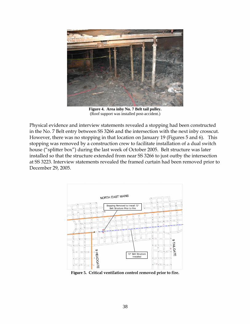
38
Figure 4. Area inby No. 7 Belt tail pulley. (Roof support was installed post-accident.)
Physical evidence and interview statements revealed a stopping had been constructed in the No. 7 Belt entry between SS 3266 and the intersection with the next inby crosscut. However, there was no stopping in that location on January 19 (Figures 5 and 6). This stopping was removed by a construction crew to facilitate installation of a dual switch house (“splitter box”) during the last week of October 2005. Belt structure was later installed so that the structure extended from near SS 3266 to just outby the intersection at SS 3223. Interview statements revealed the framed curtain had been removed prior to December 29, 2005.
72” Belt Structure Installed
Stopping Removed to Install 72”Belt Structure Prior to Fire
Figure 5. Critical ventilation control removed prior to fire.

39
Figure 6. Location where belt structure was installed after removal of a stopping.
Pairs of equipment doors were constructed to facilitate passage of men and equipment along the NEM roadway to pass under the longwall belt. The configuration of the ventilation controls and mine layout necessitated the construction of at least two stoppings for the pair of equipment doors installed between SS 3267 and SS 3333 to form an airlock, as required by § 75.333(d)(3). The stoppings which would have been necessary to form this airlock would also have separated the two air courses. Although it was not concluded whether an airlock was ever established at this location, it was determined that no airlock was established between SS 3267 and SS 3333 on January 19.
• One of the stoppings had been constructed between SS 3266 and the travel roadway, in the crosscut where the electrical installations for 9 Headgate longwall belt drive and takeup storage unit were located. The stopping was reportedly removed to reduce the accumulation of heat in the crosscut where the electrical installations were located. Two midnight shift electricians were observed removing the stopping. Physical evidence and interview statements indicated this stopping was removed prior to the fire (Figures 7 and 8).
• The installation of another single stopping could have completed the airlock
between SS 3267 and SS 3333. The location of that single stopping was in the crosscut on the side of the roadway opposite the longwall belt electrical installations. Alternatively, a series of stoppings in NEM between 9 Headgate and 9 Tailgate could have completed the airlock. Physical evidence and mine rescue and recovery logs and maps revealed neither the single stopping nor several of the individual stoppings in this alternative series were in place on January 19.

40
Figure 7. Additional critical ventilation control removed prior to fire.
Figure 8. Former location of stopping at the electrical installation.
Compliance with the existing Belt Air Rule would have prevented the two fatalities.
Belt Air Regulations
On April 2, 2004, the final Belt Air Rule was published in the Federal Register. The rule was promulgated after many years of experience under the petition for modification process. On January 21, 2000, Aracoma Coal Company filed a petition for modification of § 75.350. The petition, granted by MSHA on May 3, 2000, allowed air coursed through belt entries to be used to ventilate working places, conditioned upon
72” Belt Structure Installed
Stopping Removed Prior to Fire

41
compliance with seventeen specific terms and conditions of the petition. At that time, use of belt air to ventilate working places was prohibited except under petition for modification, approved petitions which were determined to have provided equal protection to the applicable regulation. The final rule superseded all granted petitions. The final rule included a number of conditions the mine operator is required to maintain to use belt air to ventilate working sections and areas where mechanized mining equipment is being installed or removed. The mine operator failed to comply with more than 25 regulatory provisions of the final Belt Air Rule at the Aracoma Alma Mine #1 on January 19. Most of these regulatory provisions had been included in the terms and conditions of the petition that was superseded by the Belt Air Rule. Two of the provisions were related to the approved mine ventilation plan. Several of the regulatory provisions, such as failure to separate the belt air course from other air courses, failure to provide an alarm unit for 2 Section, failure to withdraw miners in the event of a CO alarm signal, failure to report alert and alarm signals to appropriate personnel, and failure to adequately train AMS operators, had significant impact on the outcome of the January 19 fire. Had the mine operator been in compliance with the Belt Air Rule, the fire would not have resulted in the two fatalities.
Atmospheric Monitoring System A Pyott-Boone AMS, Model 9500, was installed at the mine to measure carbon monoxide concentrations along the entire underground belt system. Approximately 44 carbon monoxide sensors were installed in the belt entries to provide early warning of a fire (Figure 9).
Figure 9. Carbon monoxide sensor.

42
The locations of the CO sensors are shown in Appendix N. An alarm unit was installed underground at the longwall headgate to provide visual and audible signals in the event of a single CO alarm signal or alert signals from two consecutive CO sensors (Figure 10).
Figure 10. Remote alarm unit in headgate area on longwall section.
To function properly, the mine operator was required to program the AMS computer to respond to individual CO sensor signals so that specific CO sensors would automatically activate the appropriate alarm unit. The AMS computer, printer, visual display, and means of communication with underground locations were located in the dispatcher’s office (Figure 11).
Figure 11. AMS in dispatcher’s office located in Box Cut on surface.

43
The dispatcher’s office was located on the surface in the shop area of the Box Cut, adjacent to the warehouse and the lamp room. AMS alert, alarm, and malfunction signals were received on the surface in the dispatcher’s office. The AMS computer automatically generated a printed record of all alert, alarm, and malfunction signals. This printed record was identified as the AMS event log. Visual and audible AMS alert, alarm, and malfunction signals were provided through the AMS computer for the AMS operator in the dispatcher’s office. As an additional means of providing audible and visual notification on the surface, a strobe light and horn were also installed in the open area of the Box Cut shop. Section 75.351(e)(3) did not permit CO sensor spacing to exceed 1,000 feet in belt entries where air was used to ventilate working sections. As noted previously, alert and alarm levels of CO were 5 and 10 ppm, respectively. The minimum air velocity permitted in the belt entry was 50 fpm. The mine operator used the term “warning” in place of “alert” in approved plans, documentation, and computer programming to identify when 5 ppm CO was detected by a CO sensor. Required responses to signals from the system were specified in § 75.352, as well as in the approved mine emergency evacuation and firefighting program of instruction. In response to AMS alert, alarm, and malfunction signals received at the surface, dispatchers reportedly contacted mine foremen, supervisors, electricians, belt examiners, and/or beltmen to investigate causes of the signals. Alert, alarm, and malfunction signals were received on the surface in the dispatcher’s office. All alert, alarm, and malfunction signals were required to be recorded in a properly identified record book. The required record of alert, alarm, and malfunction signals generated by the AMS was maintained by the dispatchers in a mine record book identified as the CO Log Book. The recordkeeping requirements for alert and alarm signals specified in § 75.351(o) included the date, time, location, type of sensor and the cause for the activation of the signal(s). Similar records were required for malfunction signals. The format of the first page of the CO Log Book consisted of columns labeled as “Date,” “CO #,” “Down On,” “Who Notified,” and “Action Taken.” The first entry in the book is dated December 2, 2004, and the last entry is dated January 19, 2006. Functional tests of alert and alarm signals were required to be conducted every 7 days. Each CO sensor was required to be calibrated at intervals not to exceed 31 days. These tests and calibrations were required to be recorded and the records retained at a surface location for at least one year. To utilize belt air to ventilate the working sections per § 75.350, the AMS was to be installed and maintained as specified in § 75.351. The mine operator was also required to designate an AMS operator to monitor and properly respond to all AMS signals. At Aracoma Alma Mine #1, the dispatcher was the AMS Operator. The dispatcher also issued supplies from the warehouse, and cap lamps and hand-held detectors from the lamp room. The regularly scheduled work hours for dispatchers provided for an

44
overlap so that two dispatchers were on duty at the beginning of each shift. This overlap enabled one dispatcher to remain on duty in the dispatcher’s office while the other worked in the warehouse or lamp room during that time. Dispatchers were occasionally required to perform duties outside the dispatcher’s office during their shift. Three schematic diagrams that were visible on the AMS computer display were used to identify the locations of AMS CO sensors along the belts. A mine map posted on the wall behind the dispatcher’s desk was intended to indicate sensor locations and air directions. As part of the investigation, the AMS was tested to determine if the system would respond as intended to alert and alarm levels of CO applied to properly calibrated CO sensors in communication with the AMS computer. The CO sensors responded as designed. The alert and alarm signals activated the visual and audible alarm in the dispatcher’s office and were seen and heard by the AMS operator on the surface. The alarm unit on the longwall headgate, installed as a replacement for the unit removed after the fire, also responded properly and was seen and heard by persons in the longwall section headgate area. The alert and alarm signals, as well as calibration of the sensors, were recorded on the AMS event log as expected. AMS Event Log A printout of the AMS event log was reviewed for the period from December 31, 2004 to January 20, 2006. The AMS event log included dates and times for AMS alert, alarm, and malfunction signals, CO sensor calibrations, and belt functions for the NEM and 2 Section belts. Much of the information contained in the AMS event log was not related to the fire that occurred on January 19. The dates and times shown on the AMS event log were based on the AMS computer time clock. The AMS computer time clock was not synchronized with the actual time. The National Institute of Standards and Technology (NIST) is a non-regulatory agency of the US Department of Commerce that maintains the official time for the United States. On February 6, comparisons were made to correlate the time shown on the AMS computer with the actual time maintained by NIST. It was determined the AMS computer clock was approximately 23 minutes fast. All references to AMS event log times made in this report contain the subtracted 23 minutes to correct the AMS computer time to the approximate actual time. On January 25, CMS&H District 4 personnel noted similar differences. AMS Sensor Calibration Records Records of CO sensor calibrations were entered in the Examinations of Electrical Equipment record book. No other records identified as being used for AMS tests and calibrations were provided by the mine operator. The record of CO sensor calibrations

45
was incomplete and not maintained in a record book separate from records other than those required by § 75.351(o). Mine records and statements revealed calibrations of CO sensors were not conducted as required and were not properly recorded. Mine records and the AMS event log revealed that all CO sensors were not calibrated within the 31-day period prior to the fire. The record book indicated that CO sensor calibrations were conducted on only three days. Calibrated sensors were identified by groups rather than by individual sensor number. The calibration record book indicated “calibrated CO’s from 2 Section #2 Belt to #1 Belt Head” on January 5, 2006; “calibrated longwall CO’s” on January 9, 2006; and “Calibrated Rum Creek CO’s” on January 10, 2006. The AMS event log indicated calibrations of CO sensors along with other information. Representatives from the AMS manufacturer indicated that all sensor calibrations should have been automatically recorded in the AMS event log if the event log was running during calibrations. It was not determined if the AMS event log was running during all calibrations. The AMS event log revealed only 8 of approximately 45 CO sensors in the AMS were calibrated within the 31 day period prior to the fire. The AMS event log data also indicated the CO sensor calibrations were not always properly conducted. The mine record book also indicated all CO sensors in the AMS were not calibrated within the 31-day period prior to the fire. Discrepancies existed between calibrations noted in the record book and those in the AMS event log. Calibrations of CO sensors listed in the Examination of Electrical Equipment record book were not shown in the AMS event log. In addition, the AMS event log indicated calibrations were conducted that were not recorded in the record book. The AMS event log indicated CO Sensors 81 and 82, which first responded to the fire on January 19, 2006, were last calibrated on December 2, 2005, 49 days prior to the fire. Those calibrations were not included in the Examination of Electrical Equipment record book. Laboratory Testing The section alarm and CO sensor located at the longwall headgate were removed from the mine. On May 23, 2006, the units were examined and tested at MSHA’s Approval and Certification Center in Triadelphia, WV, to determine their operational status. Tests were conducted to evaluate the condition of the equipment, assess the response of the sensor and alarm to application of CO to the sensor, and determine the operation of test buttons on the units. During the initial examination, the internal battery of the alarm unit was found to be disconnected. Tests were conducted on the LED warning signals and audible alarm signals. On June 1, additional tests were completed at MSHA’s Pittsburgh Safety and Health Technology Center to fully evaluate the sound levels of the alarm unit.

46
The visual warning and audible alarm signals were significantly diminished because the battery was disconnected. The unit was originally shipped from the manufacturer with the battery disconnected. The instruction manual for this unit indicated the battery was to be connected prior to use. It was not determined if the battery had been connected during initial installation, or if the battery had been disconnected some time after installation. Laboratory tests revealed the LED illuminance was reduced by over 98 percent and the sound level was reduced by 68 percent, as compared to tests with the internal battery properly connected. The CO sensor, Pyott-Boone Electronics Model 1711 CO Monitor, had not been evaluated by MSHA for use in areas where electrical equipment was required to be permissible. On January 19, this CO sensor was located in an area where permissible electric equipment was required. A complete report of these tests is available from the Electrical Safety Division of the MSHA Approval and Certification Center.
There was no CO alarm unit provided for 2 Section, where 12 miners were working on January 19, 2006.
AMS Installation and Maintenance Related Deficiencies Basic AMS requirements are included in § 75.351. The mine operator did not comply with the following provisions of this Section:
• The map and these schematics provided in the dispatcher’s office did not show the intended airflow direction at each CO sensor location as required.
• Sensor spacing exceeded the 1,000-foot maximum distance at multiple locations.
Air ventilating the belt entries where these CO sensors were located was used to ventilate 2 Section and was intended to be used to ventilate the longwall section.
• Although § 75.351(e)(4) required CO sensors to be installed within 100 feet
downwind of belt transfer points, no CO sensor was installed within 100 feet downwind of the transfer point from the No. 7 Belt to the No. 6 Belt.
• The mine operator failed to provide a two-way voice communication system in
an entry separate from an entry containing the AMS as required by § 75.351(r). The pager mine phone system utilized two wires within the AMS cable bundle. The AMS cable bundle for the CO sensors along the longwall belt was installed in the longwall belt entry. During the fire that occurred in the longwall belt entry on January 19, 2006, AMS communication with CO sensors located in the 9 Headgate longwall belt entry and mine phone communication with the longwall section failed.

47
• § 75.351(c) required visual and audible signals to be automatically provided at all affected working sections when the CO concentration at any sensor reached the alarm level.
o The alarm unit on the longwall section was not activated automatically
when the CO concentrations at the CO sensors located near the longwall belt drive reached the alarm level. Statements revealed the AMS computer was not properly programmed to automatically provide alarm signals for the longwall section.
o The longwall section alarm unit was located where it could not be readily
seen and heard by miners working on the longwall section.
o The longwall section alarm unit was not maintained in proper operating condition because the internal battery was not connected to the alarm circuit. The manufacturer’s instruction manual specified the internal battery must be connected. The absence of power from an internal battery significantly diminished the visual display (LED) and also reduced audible sound levels.
o No AMS alarm unit was installed on 2 Section. An AMS alarm unit
should have been properly installed and maintained at a location where it could be seen or heard by miners working on 2 Section. A properly installed and maintained alarm unit on 2 Section would have automatically provided visual and audible notification to the miners on that section at the time of the first CO alarm signal. Automatic notification of the miners on 2 Section would have expedited their withdrawal and evacuation on January 19.
• The weekly functional tests of alarms were not properly conducted. These tests
were required for all alarm units installed both underground and on the surface. The mine operator failed to provide a record of the weekly functional tests required to be maintained by § 75.351(n)(2). At least one longwall headgate operator was unaware that an alarm unit was installed in the headgate area. The strobe light and horn installed in the open area of the Box Cut shop was not functioning properly at the time of the fire. According to interview statements, the AMS signals could not be seen or heard from the warehouse, lamp room, and at other locations in the Box Cut area. Deficiencies in the performance of the alarm units should have been identified and corrected during properly conducted functional tests.
• Not all CO sensors were properly located in the belt entry. CO sensors must be
located near the center of the entry in locations where airflow patterns permit products of combustion to be carried to the sensors to comply with § 75.351(d)(2).

48
CO sensors were installed against the rib in at least two locations in the belt entries (Sensor 50, located near the No. 6 Belt drive, and Sensor 70, located in the NEM belt entry). The longwall headgate Sensor 102 was attached to the rear of a metal plate used to support the emulsion valves, facing the rib and not located in the center of the entry.
• As discussed previously a permanent DA was required to be established to
monitor respirable dust levels in the belt entries used to ventilate the working sections. While a DA was established for the longwall section, there was not a DA established for 2 Section. The mine ventilation plan had not been amended to include the required information prior to using air from a belt air course to ventilate 2 Section.
• No CO or smoke sensors were installed in the primary escapeway for the longwall
section and 2 Section as required. • The CO sensor installed at the longwall headgate (Sensor 102) did not meet the
requirements of § 75.1002(a). • Mine records and interview statements indicated all CO Sensors were not properly
calibrated. Alert, Alarm, and Malfunction Signal Response Deficiencies A comparison of the mine operator’s AMS Log Book with the printed AMS event log revealed that all the alert, alarm and malfunction signals received on the surface were not recorded as required in the CO Log Book. The record book did not include all of the information required by § 75.351(o), including the cause of many alert and alarm signals. In addition, interview statements and mine records revealed improper responses to AMS alert, alarm, and malfunction signals. Multiple alarm signals recorded in the AMS event log required notification and prompt withdrawal of miners in affected areas to a safe location. Mine records and interview statements indicated that miners on the working section in the affected area were not withdrawn promptly when a fire occurred on December 29, 2005. During that fire, alarm signals from six different CO sensors were received on the surface. The dispatcher initiated an investigation of the alarm signals. The AMS event log revealed the AMS alarm unit on the longwall section, which was an affected area, was not automatically activated as required. On January 19, the AMS event log indicated numerous communication failures occurred with Sensor 75 which were not recorded in the AMS Log Book. Beginning at approximately 8:34 a.m., a total of 38 communication failures, indicated as “Communications Dead” on the AMS event log, were recorded for Sensor 75 prior to

49
the fire being detected. There was no record of an investigation of the cause of the malfunction signal and the condition was not corrected. As further evidence of AMS malfunction, the AMS event log did not indicate a response was received from Sensor 75 to CO produced by the fire. During the fire, sensors located both inby and outby Sensor 75 in the same belt entry responded properly and indicated alarm levels of CO. Continued operation of the belt would have required the immediate repair of the sensor and patrolling of the affected area by miners using equivalent hand-held gas monitors, as required by § 75.352(e), until repairs were completed. Although the malfunction continued and the belt was operated on the afternoon shift, no person was assigned to patrol the affected area. AMS Response on January 19, 2006 The AMS event log was used to develop the following summary of alert and alarm signals, specific malfunction signals, and belt stoppages occurring on January 19. On that day, there were two AMS alert signals recorded in the AMS event log prior to the fire; both were at Sensor 82, and occurred hours prior to the fire. At approximately 2:13 a.m. and 11:16 a.m., alert levels of CO were detected by Sensor 82, with a duration of approximately 1 minute and 6 seconds and 1 minute and 25 seconds, respectively. Interview statements and the CO log book indicated the dispatcher on duty did not notify the appropriate personnel nor properly document the events. There was no record of an investigation to determine the cause of the alert signals. It is not known whether these alert signals were related to any events or conditions that caused the fire. The day shift belt examiner first observed haze at the longwall belt takeup storage unit and drive around 10:00 a.m. Repeated attempts to identify the source of the haze were unsuccessful. Reportedly, the air cleared without further incident by the end of his shift.

50
Table 4 - Abridged AMS Event Log from January 19, 2006
Time Sensor Signal 02:12:43 82 Warning 11:16:23 82 Warning 17:13:34 82 Warning 17:13:55 82 Alarm 17:15:44 81 Warning 17:16:05 81 Alarm 17:39:22 6 Belt Boss – STOP –Remote (from Master Station) 17:39:26 8 Belt Boss – STOP –Sequence 17:39:34 7 Belt Boss – STOP –Sequence 17:59:37 82 Communications Dead 17:59:38 83 Communications Dead 18:10:50 71 Warning 18:11:05 71 Alarm 18:15:30 81 Communications Dead 18:16:17 80 Communications Dead 18:16:19 73 Warning 18:16:50 73 Alarm 18:30:19 74 Warning 18:31:35 74 Alarm 18:40:21 72 Warning 19:07:30 76 Communications Dead 19:08:22 77 Warning 19:08:35 76 Gained Communications 19:08:35 76 Warning 19:09:40 76 Alarm 19:10:23 77 Alarm 19:13:33 79 Warning 19:15:18 79 Alarm “Communications Dead” indicates a loss of communication between the AMS computer and CO sensors. “Gained Communications” indicates communication between the AMS computer and CO sensors was restored. “Warning” is the term the mine operator used to indicate alert levels of CO. Figure 12 illustrates the location of CO Sensors 82 and 83, which were in the area where the fire originated. According to the AMS event log, the first sensor to detect an alert level of CO was Sensor 82. This indicated the direction of airflow was from the belt takeup storage unit toward Sensor 82 at the time the CO was detected. An alarm level of CO was detected at Sensor 82 at approximately 5:14 p.m., 21 seconds after the alert level. An alarm level of CO was detected at Sensor 81 at approximately 5:16 p.m., also 21 seconds after the alert level.

51
Figure 12. Relative CO Sensor Locations on January 19, 2006.
The “Belt Boss” entries in the AMS event log indicated the time the NEM and 2 Section belts were stopped. The 2 Section belt was stopped 25 minutes after the first CO alarm signal was indicated by the AMS. As the fire continued to burn, additional alert and alarm signals were recorded for CO sensors located along the NEM and 2 Section belts. These signals indicated CO from the fire contaminated not only the intake air being coursed toward 2 Section, but also the NEM belt air course. With the exception of Sensor 75, sensors along the 48-inch No. 2 Section belt inby the longwall headgate indicate contaminants from the fire were entering the 48-inch belt. The contaminants traveled from the point of entering the belt

52
to the No. 2 Section loading point. Communication problems between the AMS computer and Sensor 75 occurred throughout the day. There was no record in the AMS event log of alert or alarm conditions for Sensor 75. CO sensors properly communicating with the AMS computer appeared to respond as designed. Since CO Sensors 81 and 82 were destroyed by the fire, it could not be determined if the sensors had been properly positioned within the entry. Based upon mine records and interviews with miners it could not be determined if sensors 81 and 82 were maintained in a manner which provided proper detection of CO produced by the developing fire.
Electrical System The Aracoma Alma Mine #1 was supplied power by American Electric Power. The incoming power at the Box Cut portal was supplied at 138,000 volts and was transformed to 12,470 volts at a surface substation. Two separate 12,470 volt circuits supplied power to the underground portion of the mine north of the Box Cut. One circuit (longwall circuit) provided power to the 9 Headgate longwall section, the 9 Headgate longwall belt drive power center/belt starter, and to the future 10 Headgate longwall section. The longwall circuit entered the mine through the No. 1 Entry of the Box Cut portal. The other circuit (miner circuit) supplied high-voltage power to the Nos. 4, 5, 6, and 7 belts, the 2 Section belts, and the 3 Section belts, the continuous mining machine sections, the dewatering pumps, and the freshwater pumps. The miner circuit entered the mine from the surface through a bore-hole located two crosscuts inby the Box Cut portal in the No. 2 Entry. The #20 KVA transformer, between SS 1640 and SS 1639 in the North West Mains, supplied 480 volt three phase AC power to the freshwater pumps. The freshwater pumps were located in the crosscuts on both sides of SS 1649 intersection in the North West Mains. The longwall and miner circuits are shown in Appendices O and P. The 12,470 high voltage power circuit entering the mine from the Rum Creek Portal supplied electrical power to the Nos. 1, 2, and 3 Belts, and other electrical circuits. The longwall circuit provided high-voltage power to the 9 Headgate longwall belt drive area. The high-voltage power came to a dual switch house located at the old 8 Headgate panel at the end of the North West Mains. The circuit continued as a branch into the NEM to the dual switch house for the 9 Headgate longwall section, located in the crosscut adjacent to SS 3266. Power then fed through the dual switch house to the 2,500 KVA longwall belt power center/belt starter. The longwall belt power center/belt starter provided power to the 9 Headgate longwall belt drive dual 750 HP, 500 VDC belt controllers and motors, and the 150 HP Constant Tension Vector Winch Controller located in the same crosscut.

53
Electrical Examinations and Tests Sections 75.512 and 75.512-2 require that at least weekly, all electrical equipment must be examined, tested, and maintained to assure safe operating condition. A record of such examinations was required to be maintained. Section 75.900-3 requires all low-voltage and medium-voltage circuit breakers and their auxiliary devices to be tested and examined at least monthly. The record of examinations and tests required by § 75.512 were maintained by the mine operator in the Examination of Electrical Equipment record books. Individual record books were used to record the examinations and tests of electrical equipment in various areas of the mine. Specific electrical equipment components were not identified individually in the record book. The 9 Headgate longwall belt takeup storage unit was not specifically identified in any of the record books. It could not be determined if the belt takeup storage unit was examined at the same time as the longwall belt drive. There was no record to indicate all required examinations and tests were conducted. The last record of examinations and tests of the 9 Headgate longwall belt electrical equipment was made on January 18. Interview statements indicated the examinations and tests were actually conducted on the midnight shift on January 19. The examination was inadequate because the following dangerous conditions, which existed at the time of the fire, were not identified in the examination record:
• The electrical control switch cable for the water sprinkler water flow valve was not secured with a proper fitting where it entered the metallic frame of the 9 Headgate longwall belt deluge control box.
• The ground monitor was intentionally disabled for the cooling fan on the
9 Headgate longwall belt winch motor. It was not determined if the ground monitor was disabled at the time of the examination.
The record of tests and examinations required by § 75.900-3 were maintained by the mine operator in the Examination of Electrical Equipment record books. There was no record to indicate all required tests and examinations were conducted. The last record of examinations and tests of the 9 Headgate longwall belt electrical equipment was made on January 18. Interview statements indicated the examinations and tests were actually conducted on the midnight shift on January 19. Inspection of the 9 Headgate Longwall Belt Drive Electrical Components During the investigation of the accident all the electrical controls installed at the 9 Headgate longwall belt drive were inspected. The inspection of the electrical controls did not reveal any conditions that could be attributed to the source of ignition for the fire.

54
Inspection of the 2,500 KVA 9 Headgate longwall belt drive power center/belt starter revealed that the ground monitor for the #1 750 HP motor was observed with a short length of wire attached to the No. 4 terminal. This wire was in close proximity to the No. 3 terminal, but was not connected to it. Although it appeared the wire may have previously been used to defeat the ground monitor, it was not connected to both terminals at the time of the inspection. The inspection of the longwall belt takeup storage unit winch control box indicated the ground monitor was intentionally disabled for the cooling fan on the 9 Headgate longwall belt winch motor. A short length of wire was connected to the No. 3 and No. 4 terminals. The deluge control box attached to the 2,500 KVA power center/belt starter was also examined during the inspection of the electrical components. The unit was installed to provide an audible alarm, and to stop the belt in the event water flowed through the water sprinkler system. The control box was not wired in a functional method because the cable entering the box was not entered through a proper fitting. In addition, one of the conductors (white wire) of the Number 14 AWG, three conductor, cable from the flow sensor, was not attached to the proper terminal. This cable provided power through the flow sensor normally open interlock installed in the water sprinkler system installed at the 9 Headgate longwall belt drive. It could not be determined if the wire had become disconnected during the fire, firefighting and recovery efforts, or during the accident investigation inspection. The unattached wire would prevent the belt from stopping and the activation of the audible alarm during operation of the water sprinkler system. Water Sprinkler System for the 9 Headgate Longwall Belt Section 75.1101-11 requires, in part, that each water sprinkler system be examined weekly and a functional test of the complete system be conducted at least once a year. The record book labeled “Mother Drive Examination of Electrical Equipment” contained results of examinations of the water sprinkler system for the belt drive, takeup storage unit, electrical control, and gear-reducing unit for the 9 Headgate longwall belt. Records indicated the water sprinkler system was examined on November 6, 2005, November 25, 2005, and visually examined on January 18, 2006. A review of the record book revealed not all the required weekly examinations of the water sprinkler system were conducted. An adequate weekly examination of the water sprinkler system for the 9 Headgate longwall belt drive and takeup storage unit was not being made, and no record of the yearly functional test was found.

55
There was no fire suppression system installed on the longwall belt takeup storage unit, where the fire originated.
The electrical components and belt takeup storage unit were not provided with any type of fire suppression system that would actuate in the event a rise in temperature occurred at this location as required by § 75.1101-8(a). This hazardous condition was not identified and recorded at the time of the examination. Proper examinations would have revealed the absence of an adequate and complete water sprinkler system.
Escapeways, Escapeway Maps and Drills Section 75.380 requires at least two separate and distinct travelable passageways designated as escapeways from each working section, continuous to the surface drift opening or to the escape shaft or slope opening to the surface. Further, each escapeway is required to be maintained in a safe condition to always assure passage of anyone, including disabled persons. Each escapeway must be clearly marked to show the route and direction of travel to the surface, and must be located to follow the most direct, safe, and practical route to the nearest mine opening suitable for the safe evacuation of miners. Sections 75.380(f) and (g) address primary escapeways specifically. Section 75.380(f) requires one escapeway that is ventilated with intake air to be designated as the primary escapeway. As stated in § 75.380(g), except where separation of belt and trolley haulage entries from designated escapeways did not exist before November 15, 1992, and except as provided in § 75.350(c), the primary escapeway must be separated from the belt and trolley haulage entries for its entire length, to and including the first connecting crosscut outby each loading point except when a greater or lesser distance for this separation is specified and approved in the mine ventilation plan and does not pose a hazard to miners. The mine entries in the NEM were developed after 1992. Section 75.350(c) requires approval in the mine ventilation plan for additional intake air to be added to the belt air course through a point-feed regulator. The location and use of point-feed regulators must be approved in the mine ventilation plan. On January 19, 2006, no point-feed regulator was approved in the mine ventilation plan at Aracoma Alma Mine #1. Section 75.350(c) does not permit air from the belt air course to enter an intake air course that is a designated primary escapeway. Further, § 75.333(b)(4) requires permanent stoppings or other permanent ventilation control devices be built and maintained to separate the primary escapeway from belt and trolley haulage entries, as required by § 75.380(g). Section 75.383 lists requirements for escapeway maps and drills. § 75.383(a) requires a map is to be posted or readily accessible to all miners in each working section, and in each section where mechanized mining equipment is being installed or removed. The

56
map shall show the designated escapeways from the working section to the location to where miners must travel to satisfy the escapeway drill specified in § 75.383(b)(1). A map showing the main escapeways is required to be posted at a surface location of the mine where miners congregate, such as at the mine bulletin board, bathhouse, or waiting room. All maps are required to be kept up-to-date, and any changes in route of travel, locations of doors, or directions of airflow shall be shown on the maps by the end of the shift on which the changes are made, and affected miners informed of the changes before entering the underground areas of the mine. Miners underground on a shift when any such change is made are to be immediately notified of the change. The routes of the primary and alternate escapeways for 2 Section and the 9 Headgate longwall section shown on the map posted at the surface location where miners congregated are depicted in Appendix Q. Section 75.1202-1(b)(4) requires temporary notations for escapeways designated by means of symbols to keep up-to-date the map(s) required by § 75.1202-1. The escapeways marked on the map identified by mine operator representatives as the map that § 75.1202-1 required to be kept up-to-date with temporary notations showing escapeways did not reflect the route of the underground markings. No alternate escapeway routes were marked on the § 75.1202-1 map for 2 Section and the 9 Headgate longwall section. Further, the primary escapeway routes marked on the § 75.1202-1 map for 2 Section and the 9 Headgate longwall section did not accurately reflect the actual routes marked underground by reflective tags. Section 75.383(b)(1) requires practice escapeway drills to be conducted at least once every 90 days for all miners. Each miner on a working section is required to travel the primary or alternate escapeway from the working section to an area where the split of air ventilating the working section intersects a main air course, or 2,000 feet outby the section loading point, whichever distance is greater. An escapeway drill shall not be conducted in the same escapeway as the immediately preceding drill. Section 75.383(b)(2) requires practice escapeway drills to be conducted at least once every 6-weeks. At least two miners on each coal producing working section who work on that section, accompanied by the section supervisor, shall travel the primary or alternate escapeway from the section to the surface, to mechanical escape facilities, or to an underground entrance to a shaft or slope to the surface. Systematic rotation of section personnel shall be used so that all miners working on that section participates in a 6-week drill. An escapeway drill shall not be conducted in the same escapeway as the immediately preceding drill. An escapeway drill conducted to fulfill the requirements of the 6-week drill may also fulfill the requirements of the 90-day drill. Underground Escapeways The mine operator used reflective tags hung from the mine roof to mark the routes of the underground escapeways. Green colored reflective tags were used to indicate the

57
primary escapeway route and amber colored reflective tags were used to indicate the alternate escapeway route. Both types of reflective tags were red colored on the back side. The markers were to be hung such that a miner following either the green or amber color would travel in the proper escape direction to the surface of the mine. The red-colored sides of both the green or amber reflective tags were to indicate that the miner was traveling in the wrong direction for escape when following the red color. The green reflective tags that were visible in the primary escapeway were mapped by MSHA investigators. The escapeways were intended to lead miners from the sections in escape routes that exited the mine through drift openings in the Box Cut. The locations of the tags marking the primary escapeways for 2 Section and 9 Headgate longwall section are shown in Appendix R.
Mine maps located on the surface and underground did not accurately depict permanent ventilation controls or escapeways.
Main Escapeways The main escapeways for the underground working sections were located in the North West Mains. A map showing the main escapeways was posted under a clear plastic cover on a wooden table at a surface location where miners congregated in the waiting area prior to the beginning of the shift. The routes of the main primary and alternate escapeways for 2 Section and 9 Headgate longwall section shown on this map are depicted in Appendix Q. The main primary and alternate escapeways terminated on the surface at the Box Cut openings. The underground primary and alternate escapeway routes marked by reflective tags were not accurately depicted on the map maintained on the surface map. Escapeways from 2 Section The primary escapeway for 2 Section was marked with green reflective tags in the intake air course of NEM. The route of the primary escapeway was not clearly marked. Although the regulation requires a distinct, clearly marked, escapeway to be designated, green reflective tags between 2 Section and the North West Mains were located in multiple parallel mine entries, indicating multiple escapeway routes. All changes in the direction of the multiple routes were not clearly marked. The escapeway maps required by § 75.383(a) did not reflect the underground route that was marked with the greatest number of green reflective tags. The underground route marked with the greatest number of green reflective tags followed the roadway from 2 Section to the equipment doors located inby the longwall belt. The primary escapeway reflective tags did not follow the roadway through the equipment doors, but diverted from the roadway through a crosscut at SS 3333 in a northwest direction. Visible reflective tags marking this route were not observed shortly after making the turn to the northwest without making another turn. A miner traveling this route and continuing in the

58
direction indicated by the reflective tags would have encountered the 72-inch belt structure installed in the entry adjacent to the roadway. This belt structure was an obstruction to a miner traveling this route. The route marked with reflective tags continued across the overcast at SS 3221 and then rejoined the roadway on the southwest side of the outby equipment doors at the longwall belt drive. The primary escapeway route marked by green reflective tags continued to the North West Mains and then on to the surface at the Box Cut. The alternate escapeway for 2 Section was not clearly marked to show the route and direction of travel to the surface. The escapeway map on 2 Section was readily accessible to all miners and showed the alternate escapeway to be in the NEM belt entry to the North West Mains. The escapeway map that was readily accessible to miners on 2 Section was inaccurate. An image of the escapeway map is shown in Appendix S. The mine workings shown on the map were not up-to-date. Although 2 Section was developed into 11 Headgate, the 2 Section faces shown on the map were just inby 10 Headgate in NEM. Mine entry projections shown on the map did not extend to 11 Headgate where the 2 Section mining operations were being conducted. The primary and alternate escapeways were not shown extending into 11 Headgate. Section 75.333(c)(2) requires all personnel doors in stoppings along escapeways to be clearly marked so that the doors may be easily identified by anyone traveling in the escapeway and in the entries on either side of the doors. Reflective “mandoor” signs were hung from the mine roof in the intake entry adjacent to the NEM belt entry. These signs identified locations of some personnel doors in stoppings that separated the primary escapeway in the NEM intake air course from the NEM belt entry. Not all personnel door locations were marked with the reflective signs. No sign was found to identify the location of the personnel door installed in the crosscut between the primary escapeway and the alternate escapeway in the NEM belt entry at SS 3230. This is the personnel door through which miners evacuating from 2 Section crossed from the primary escapeway to the alternate escapeway. Removal of permanent stoppings located inby SS 3249 eliminated the separation between the No. 7 Belt entry and the primary escapeway for 2 Section. Holes existed in numerous stoppings located between the 2 Section primary escapeway and the NEM No. 1 Belt entry. These missing stoppings and holes compromised the separation between the No. 7 Belt entry and the primary escapeway for 2 Section. 9 Headgate Longwall Section Escapeways The primary escapeway route for the longwall section was clearly marked with green reflective tags in the No. 1 Entry intake air course of 9 Headgate, through the cut through at SS 3305, and into the North West Mains.

59
On January 19, 2006, there was no alternate escapeway route marked or maintained underground to show the route and direction of travel from the longwall section to the surface. On the escapeway map posted at the surface location where miners congregated, the alternate escapeway route was shown in the No. 3 Entry of 9 Headgate, continuing in a direct line across the NEM entries to the NEM belt entry. This had been the 9 Headgate belt entry during the development of 9 Headgate. The alternate escapeway was shown on the map posted at the surface location to be routed through solid permanent stoppings at the junction of 9 Headgate and NEM. The depicted escapeway then intersected and crossed the primary escapeway for 2 Section. The two depicted escapeways were not separated by an overcast. An image of the escapeway map that was readily accessible to all miners on the longwall section is shown in Appendix T. On the escapeway map maintained on the longwall section that was readily accessible to the miners, the alternate escapeway route was also shown in the No. 3 Entry of 9 Headgate, but terminated at the intersection with the entries in NEM. An escapeway route was depicted as a primary escapeway from the point of termination in 9 Headgate to the NEM belt entry. Amber reflective tags were not found in the 9 Headgate entries to show the route and direction of travel. The escapeway routes depicted on the escapeway maps to serve as the alternate escapeway for the 9 Headgate longwall section did not meet the regulatory requirements for an escapeway.
Escapeway drills were not conducted at proper intervals, were not rotated between the primary and alternate escapeway, and did not follow the designated routes.
Escapeway Drills Records of fire drills and escapeway drills for miners at Aracoma Alma Mine #1 were maintained in Fire Drill and Escapeway Record Books. A review of the records revealed the frequency of the practice escapeway drills did not always meet the 90-day maximum interval requirement during the 12-months prior to January 19, 2006. In addition, practice escapeway drills conducted during the 12 months prior to January 19, were not always rotated between the primary and alternate escapeways. Mine records indicated that some of the miners working on 2 Section (2 Section miners) on the afternoon shift of January 19, had participated in 6-week practice escapeway drills in the alternate escapeway during the 90-day period preceding the accident. However, these same records indicated that not all of the 2 Section miners were afforded the opportunity to participate in a practice escapeway drill during that 90-day period. Interview statements from 2 Section miners revealed information about escapeway drills in which they participated. Some 2 Section miners indicated participation by the entire 2 Section crew in an escapeway drill sometime during the weeks prior to the

60
January 19, 2006, fire. The escapeway drill described was held in the primary escapeway and included riding a mantrip in the NEM roadway from 2 Section, through the sets of equipment doors at the 9 Headgate longwall belt drive area, to the 3-Way in North West Mains. The remainder of the primary escapeway to the surface was traveled on foot. Interview statements of some 2 Section miners indicated they recognized the route traveled during that escapeway drill diverted from the primary escapeway when they rode on the mantrip through the sets of equipment doors at the longwall belt. These miners stated they knew the primary escapeway passed over the overcast located outby the equipment doors. A proper practice escape drill should have followed the actual designated escapeway which diverted from the roadway north of the equipment doors and continued in the NEM intake. If the drill had been conducted properly, the miners would have then been required to exit the mantrip and walk over the overcast at SS 3221.
Mine Examinations The regulations require preshift and on-shift examinations (§ 75.360 and § 75.362) and weekly examinations (§ 75.364) and provides for supplemental examinations (§ 75.361). Requirements regarding hazardous conditions are specified in § 75.363. The regulations address posting, correcting, and recording hazardous conditions and recording corrective actions. All hazardous conditions, regardless of when detected or by whom, must be adequately addressed. Proper examinations and records serve as a history of the types of conditions that can be expected in the mine. When properly reviewed, mine management can determine if the same hazardous conditions are of a recurring nature and whether or not corrective actions have been effective. The mine foreman must be fully aware of the information contained in records of examinations so as to be able to allocate resources to correct safety problems as they develop. Some examples of hazardous conditions that would be expected to be observed, recorded, and corrected include but are not limited to: loose roof and ribs; excessive levels of methane; oxygen deficiency; damaged or improperly installed ventilation controls; a lack of proper separation between air courses where required; accumulations of loose coal, coal dust or other combustible materials; inadequate rock dust; misaligned belts causing damage to belt structure or other belt system components; damaged and/or hot belt rollers and bearings; smoldering embers; hot materials producing smoke and/or open flames; and a change in air direction that could materially affect the safety and health of the miners. If a determination is made by the mine examiner that air is not moving in its proper direction, the results of that determination must be recorded and corrective action must be taken. Certified persons conducting examinations that required a determination of whether or not air was moving in its proper direction must know the proper direction of the airflow in the area examined. Section 75.360(b) requires persons to examine for hazardous conditions, test for methane and oxygen deficiency, and determine if the air is moving in its proper

61
direction. The locations where the preshift examinations are to be conducted are also specified in the regulations and include roadways, travelways, working sections, areas where mechanized mining equipment is being installed or removed, underground electrical installations, and other areas where work or travel during the oncoming shift is scheduled prior to the beginning of the preshift examination. Section 75.362(b) requires during each shift that coal is produced, a certified person examine for hazardous conditions along each belt haulageway where a belt is operated. This examination may be conducted at the same time as the preshift examination of belts and belt haulageways. Section 75.361 requires an examination within 3 hours before anyone enters an area in which a preshift examination has not been made for that shift. The certified person conducting the examination is to examine for hazardous conditions, determine whether the air is traveling in its proper direction and at its normal volume, and test for methane and oxygen deficiency. Section 75.364(b) requires at least every 7 days, among other specifics, an examination for hazardous conditions be made at the following locations: in at least one entry of each intake air course and return air course, so that each entire air course is traveled in its entirety; and in each escapeway so that the entire escapeway is traveled. The weekly examination may be conducted at the same time as preshift or on-shift examinations conducted for the same area. No separate record of the concurrently conducted weekly examination is required. Section 75.351(n) requires at least once each shift when belts are operated as part of a production shift, sensors used to detect carbon monoxide or smoke in accordance with § 75.350(b), and § 75.350(d), and alarms installed in accordance with § 75.350(b) must be visually examined. MSHA explains in the preamble of the final rule this examination would typically be made during preshift or on-shift examinations, although a separate examination is permitted. Section 75.512 requires that electrical equipment is to be examined, tested, and properly maintained by a qualified person to assure safe operating conditions. Section 75.512-2 requires these examinations and tests to be made at least weekly.
Mine examiners failed to identify obvious hazards in the mine and deficiencies in safety systems which contributed to the severity and extent of the mine fire.
The purpose of examinations is to identify hazardous conditions and make corrections to maintain a safe working environment. The preamble to the final rule for § 75.364 explained that the weekly examination is directed at hazards that develop in the more
62
remote and less frequently visited areas of a mine, including intake and return air courses. Because of the confined nature of the underground mining environment, loss of life can result in other areas of the mine outside the immediate location of the hazard. The weekly examination assures these hazards are located and corrected. MSHA investigators reviewed mine records to determine if required examinations were conducted, the types of hazards identified during those examinations, and corrective actions taken to correct hazards. The results of examinations were recorded in designated mine record books. Not all mine examination records requested by MSHA investigators were available for review. A representative of the mine operator responded to the requests by stating the record books that were not provided did not exist.
Accumulations of combustible materials along the longwall belt were not identified and corrected, nor properly recorded in mine record books.
Preshift and On-shift Examinations 9 Headgate Longwall Belt MSHA investigators recorded the conditions found in the longwall belt entry during the investigation. The following hazardous conditions, which were determined to be present at the time of the January 19, 2006, mine fire, were not identified by the mine examiners:
• Accumulations of combustible material were present in the form of grease, oil, coal dust, coal fines, and loose coal spillage at numerous locations along the approximate 2,000 feet length of the 9 Headgate longwall belt;
• Damaged bottom rollers, bottom rollers on the ground with indications they had
been rotating in combustible material on the mine floor, and damaged top rollers;
• Damaged and missing trip latch lever posts and damaged drop-off carriage
assembly trip latch levers that affected positioning of the drop-off carriage within the 9 Headgate longwall belt takeup storage unit;
• Air in the 9 Headgate longwall belt entry was not traveling in the direction
specified in the approved mine ventilation plan;

63
• No fire suppression system of any type, which would actuate in the event of a rise in temperature, was provided for the belt takeup storage unit and electrical components; and
• Fire hose outlet valves near the longwall belt tailpiece were not provided with
handles to actuate. There were also several indications of prolonged operation of the longwall belt system while the belt was misaligned, including: • Damaged belt hangers, some partially cut through and others severed from
prolonged rubbing from the misaligned belt; • Damaged belt takeup storage unit frame components, partially cut through from
prolonged rubbing of the misaligned belt (See Figure 13); • Severed strips of belt on the mine floor and hanging on belt structure;
• Lengths of partially severed strips of belt;
• Shavings of belt on the mine floor;
• Belt cord fibers wrapped around belt roller components; and
• Extended lengths of belt with frayed edges.
Figure 13. Grooves cut into the rear frame assembly.
The last record of an examination of the longwall belt was for the preshift examination conducted by the belt examiner on the day shift of January 19, 2006. The belt examiner

64
did not sign or initial the record book by or at the end of the shift for the examinations listed in that report. Physical evidence and interview statements revealed the examination was inadequate: the examination was not complete and hazardous conditions that were determined to have existed at the time of the examination were not recorded. Although the examination record indicated air was moving in the right direction with a velocity of greater than 50 fpm, the belt examiner revealed he did not make airflow direction determinations, nor air velocity measurements (he was not provided with an anemometer or other means to measure the air velocity) during his examinations of the belt entries and was not able to identify the proper airflow direction in the longwall belt entry. In addition, interview statements revealed that not all examiners were provided adequate gas detection equipment on all shifts. Dual Switch House Installation Project Physical evidence and interview statements revealed a stopping had been constructed in the No. 7 Belt entry between SS 3266 and the next inby crosscut intersection. However, there was no stopping in that location on January 19, 2006. This stopping was removed during the last week of October 2005, by a construction crew to facilitate installation of a dual switch house in the crosscut where the electrical installation for the longwall belt drive and takeup storage unit near SS 3266 was located. Construction reports were prepared for mine superintendent Lawrence Lester by Don Hagy, outby construction foreman, to report work completed by the construction crew Hagy supervised. A construction report revealed that a scoop was used to take the dual switch house from the No. 2 “4-Way” to 9 Headgate on October 26, 2005. The report also revealed the high voltage cable for the dual switch house was installed and two ends connected. To facilitate installation of belt structure through the entry at a later date, a framed curtain was installed instead of re-constructing the removed stopping. Interview statements indicated other mine officials were aware the stopping had been removed and needed to be reconstructed. Interview statements from Hagy indicated there was no production inby that location at the time the stopping was removed. Mine records revealed 2 Section had completed mining in 10 Headgate and was being moved to the NEM on October 25, 2005. No entries for preshift or on-shift examinations conducted on 2 Section were found for the period from October 26 through November 5, 2005. Mine records showed that preshift examinations for 2 Section resumed on the afternoon shift of November 6, 2005. The section had been moved to NEM and ventilation was being established. Preshift and on-shift examination records indicate production on 2 Section resumed in the NEM on November 7, 2005.

65
An entry in the Examination of Electrical Equipment record book for 2 Section revealed the section had been moved from October 25 through October 28, 2005. Another entry in the record book indicated the 2 Section feeder and center shuttle car were located in the NEM when it was examined on November 1, 2005. Mine production records revealed 2 Section equipment in 10 Headgate was being moved on the afternoon shift of October 24, 2005. The first mine production records for 2 Section in NEM indicate production began on day shift November 7, 2005. Results of pre-shift and onshift examinations for construction work were entered into the Pre-shift – Onshift and Daily Report record books maintained for that purpose. Record books for the period prior to November 9, 2005, were not provided by the mine operator. Mine records indicated that mechanized mining equipment was being removed from 10 Headgate and installed in a new location in NEM inby 10 Headgate. Both areas were inby the No. 7 Belt tail pulley at the time the stopping was removed. Two separate and distinct escapeways were required for both 10 Headgate and the projected new section in NEM. These escapeways were required to be separated from the No. 7 Belt entry. No. 7 Belt and Underground Electrical Installations for the 9 Headgate Longwall Belt Drive and Takeup Storage Unit The last record of an examination by the belt examiner of the No. 7 Belt was for the preshift examination conducted on the day shift of January 19, 2006. Observations made underground by the MSHA accident investigation team and interview statements from the miners established the examination was inadequate; the examination was not complete; hazardous conditions that were determined to have existed at the time of the examination were not recorded; and the examination was not conducted during the required time period. The belt examiner who conducted the examination stated he was aware no stopping existed immediately inby the No. 7 Belt tail roller to separate the No. 7 Belt entry from the belt structure that had been installed in preparation for the extension of that belt. He knew the stopping across that entry, approximately 150 feet inby the No. 7 Belt tail pulley, had been removed. The belt examiner was also aware a stopping had been removed from the crosscut inby the No. 7 Belt tail roller in which the longwall belt electrical installations were located. As previously stated, the stoppings the examiner knew were missing were necessary to provide separation between the 2 Section primary escapeway and the No. 7 Belt entry. Further, the last record of an examination of the No. 7 Belt was not signed or initialed by the examiner. The examination was not complete, and hazardous conditions that were determined to have existed at the time of the examination were not recorded. The

66
examination record indicated air was moving in the right direction with a velocity of greater than 50 fpm. However, the belt examiner stated he did not make airflow direction determinations or air velocity measurements, and was unable to identify the proper airflow direction in the No. 7 Belt entry. Interview statements revealed the air that ventilated the No. 7 Belt entry traveled beyond the belt tail and into the intake air course, continuing toward 2 Section, on the afternoon shift of December 29, 2005, the date on which another fire occurred. The record book indicated an examination of underground electrical installations for the 9 Headgate longwall belt drive and takeup storage unit was conducted as part of the preshift and on-shift belt examination for January 19, 2006. No. 7 Belt Structure Extension Project The NEM roadway passed through the intersection at SS 3223. Belt structure for the No. 7 Belt extension was installed from the SS 3223 intersection outby toward 9 Headgate and inby toward 10 Headgate. The specific work locations and components installed depended on the materials available at the time. The exact date on which the belt structure for the extension of the No. 7 Belt between SS 3266 and the intersection with the next crosscut was installed could not be determined. However, observations made during the investigation, mine construction reports, and interview statements provided relevant information. The framed curtain was removed and belt structure installed from the point between SS 3266 and the next inby crosscut. Hagy, who supervised the construction crew that removed the stopping, observed its removal. Two additional mine management officials, Shadd and Herndon, reportedly were also aware the stopping had been removed. Reportedly, Shadd discussed the need to rebuild the stopping with Hagy in the presence of Herndon. These conversations reportedly occurred soon after the stopping was removed and prior to Hagy voluntarily terminating his employment at the Aracoma Alma Mine #1 the last week of October 2005. The last construction report prepared in October 2005 by Hagy was dated October 27, 2005. That construction report revealed six crosscuts of waterline were laid out in the entry where the No. 7 Belt was being extended, 12 crosscuts of belt chains were hung, and one load of top belt structure was brought in, among other work. That report contained no record of the installation of the belt structure, nor a specific location where this work was done. Hagy returned to employment at Aracoma Alma Mine #1 approximately one week later, in November 2005. In interview statements, Hagy recalled he had asked about the installation of the belt structure in that area while riding into the mine with the construction crew on the day he returned to work. He was informed by members of the

67
construction crew riding with him the work had been completed in that area and to continue work in the 10 Headgate area. Hagy stated he conducted on-shift examinations only in the areas where his construction crew worked. Preshift examinations for the day shift construction crew were conducted during the preceding shift in areas where the crew was scheduled to work. Hagy stated he did not conduct examinations in the area where the stopping was removed after returning to Aracoma Alma Mine #1 in November 2005. The first construction report, dated in November 2005, was prepared by Hagy for work performed on November 5, 2005. No construction reports were provided by the mine operator for October 28 through November 4, 2005. Correspondence between MSHA and the mine operator’s representative indicated that no other construction related reports were in the possession of the mine operator. Construction reports indicated 72-inch belt structure was installed on several days during November and December 2005. However, the reports lacked sufficient detail as to enable determination of the exact location of the installed structure. The extent of the 72-inch belt structure installed prior to the accident on January 19, 2006, is shown in Appendix C. The results of the pre-shift and on-shift examinations conducted for construction work were entered into the Pre-shift – Onshift and Daily Report mine record books maintained for that purpose. Records of the pre-shift and onshift examinations conducted for construction work from November 9, 2005, through January 19, 2006, were reviewed by MSHA accident investigators. Construction work reports were not provided to MSHA for all of the dates on which records indicated that pre-shift and onshift examinations were conducted in this area. Some of the examinations recorded in the Pre-shift – Onshift and Daily Report mine record books maintained for the construction work were made during timeframes that indicate they were supplemental examinations. Preshift–onshift examination mine record books for the period prior to November 9, 2005, were not provided by the mine operator. Correspondence between MSHA and the mine operator’s representative indicated that no other construction related record books were in the possession of the mine operator. The preshift or supplemental examinations required before allowing miners to work in this area were inadequate. Corrective actions were not taken for the hazardous condition created by the absence of the stopping necessary to provide separation between the primary escapeway for 2 Section and the No. 7 Belt Entry. Roadway from NEM to 2 Section The pre-shift and on-shift examinations of the NEM roadway were recorded in the Pre-shift – Onshift and Daily Report record book identified as “Travelways.” The record book indicates the last examination of the NEM roadway prior to the accident was

68
conducted on the day shift of January 19, 2006. The record book indicates that no hazards were observed. The record book also indicates Shadd and Edward Ellis phoned the examination outside to Plumley and Runyon. The person(s) who examined individual areas identified in the record book did not initial or sign the record book. The examination of the NEM roadway was inadequate. Hazardous conditions that existed at the time of the examination were not identified in the record book. The location of all personnel doors along the primary escapeway were not clearly marked so that the doors could be easily identified by anyone traveling in the escapeway and in the entries on either side of the doors. The lack of separation between the No. 7 Belt entry and the 2 Section primary escapeway was not identified, and the sets of equipment doors located between SS 3267 and SS 3333 were not installed to form an airlock. Weekly Examinations A mine map identified as “Air-Way Map Weekly Fireboss,” which depicted the weekly examination routes, was obtained from the mine superintendent’s office. The map showed the route of travel for air course examinations and was color coded indicating which routes were traveled each day of the week, Monday through Friday. Some of the evaluation points approved in the mine ventilation plan for the evaluation of the bleeder systems in the mine were also color coded. Interview statements revealed John McNeely, airway walker, conducted weekly examinations of air courses on the day shift. McNeely stated the air courses he examined did not include the belt air courses. He also stated he observed the ventilation controls along his route of travel. Results of the weekly examinations were entered into the Weekly Examinations for Methane and Hazardous Conditions mine record books maintained for that purpose. Records of the weekly examinations conducted between the week ending November 12, 2005, and the week ending January 21, 2006, were reviewed by MSHA accident investigators. Initials of the examiners were entered beside air courses listed in the record books. The initials indicated McNeely conducted most of the recorded examinations. The weekly examination records were inadequate because dates for each specific air course examination were not recorded. It could not be determined from the mine record books whether or not the examinations were conducted in the listed air courses and at the listed evaluation points every seven days as required. Not all air courses were listed in the weekly examination record book. Some of these air courses were routinely examined during preshift examinations. The air courses listed in the weekly examination record books were not all clearly described. Not all approved evaluation points were listed as examined in the weekly examination record books, nor were all the missing examinations of evaluation points found in any other mine examination record books. Some of the required weekly examinations of air

69
courses and evaluation points had not been conducted for an extended period of time prior to the accident. Intake Air Courses and Primary Escapeway for 2 Section There were no examination records that specifically identified the area examined as the 2 Section primary escapeway. The primary escapeway for 2 Section extended from 2 Section through the multiple-entry intake air course in NEM and North West Mains to the intersection of the No. 2 Cut-Through, where it met the primary escapeway for the longwall section. An examination of the primary escapeway for 2 Section could have been conducted during the examinations of the intake air course in NEM and in the North West Mains from the inby No 2 Cut-Through to NEM, or in combination with preshift examinations of the roadway in this area. Mine records and interview statements revealed examinations of the primary escapeway for 2 Section were inadequate. Multiple primary escapeway routes in NEM were marked with green reflective tags. The primary escapeway route marked with the greatest number of green reflective tags in NEM followed the roadway from 2 Section to the equipment doors located inby the longwall belt. The primary escapeway reflective tags did not follow the roadway through the equipment doors, but diverted from the roadway through a crosscut at SS 3333 in a northwest direction. A miner evacuating via this route and continuing in the direction indicated by the reflective tags would have encountered the 72-inch belt structure installed in the entry adjacent to the roadway. This belt structure was an obstruction to a miner evacuating via this route. The route marked with green reflective tags continued across the overcast at SS 3221 and then rejoined the roadway on the southwest side of the pair of equipment doors located outby the longwall belt drive. There was no documentation or indication the portion of the primary escapeway for 2 Section, from the roadway intersection at SS 3333 for a distance of two crosscuts toward SS 3262, was examined weekly. The primary escapeway route marked by green reflective tags continued into the North West Mains and on to the surface at the Box Cut Portal. Two routes were marked with green reflective tags as the primary escapeway in North West Mains from NEM to the No. 2 Cut-Through. Based on interview statements of the mine examiner, it was determined not all routes marked with green reflective tags as escapeways were traveled during the weekly examinations of the intake air course.

70
Weekly examinations did not identify the lack of separation between the No. 7 Belt air course and the 2 Section primary escapeway.
The examinations failed to identify the following hazards: the lack of separation between the No. 7 Belt and the 2 Section primary escapeway; holes that existed in stoppings that separated the NEM belt entry from the 2 Section primary escapeway; the lack of a clearly marked alternate escapeway for 2 Section; and the location of all personnel doors along the escapeway were not clearly marked so that the doors could be easily identified by anyone traveling in the escapeway. No. 7 Belt Air Course Because the No. 7 Belt Air Course (BAC) is an intake air course, a weekly examination for hazardous conditions was required by § 75.364(b)(1). This section requires examination of the air course in its entirety. Pre-shift and on-shift examinations of the belt would not typically cover the entire BAC, but only the portion along the belt conveyor or belt conveyor haulageway. There were no weekly examination records that specifically identified the area examined as the No. 7 BAC. It is likely that the weekly examination of portions of this BAC was conducted concurrently with the pre-shift and on-shift examinations of No. 7 Belt conveyor. In § 75.301, the belt air course is defined as “The entry in which a belt is located and any adjacent entry(ies) not separated from the belt entry by permanent ventilation controls, including any entries in series with the belt entry, including any entries in series with the belt entry, terminating at a return regulator, a section loading point, or the surface.” At the time of the fire, and for weeks prior to the fire, the air passing through the No. 7 Belt entry was moving either into the longwall belt entry, or past the No. 7 Belt tail into the 2 Section intake and on to 2 Section. The No. 7 Belt air course would have terminated at the 2 Section loading point by definition. It could not be determined from mine records if the No. 7 BAC was examined in its entirety. If the mine operator used pre-shift and on-shift examinations to comply with weekly examination requirements, which covered only the portion of the BAC containing the belt conveyor, the examinations were inadequate because the BAC was not examined in its entirety. If the No. 7 BAC was examined in its entirety, the examinations were inadequate because the examiner failed to identify the hazardous condition of the lack of separation between the No. 7 Belt air course and the 2 Section primary escapeway in NEM. This condition existed from November 2005, to the time of the fire on January 19, 2006.

71
Intake Air Course and Primary Escapeway for 9 Headgate Longwall Section There were no records of examinations that specifically identified the area examined as the longwall section primary escapeway. The primary escapeway for the longwall section was located in the single entry intake air course through which intake air was directed to the longwall section. The escapeway would have been traveled to the North West Mains intake air course during an examination of the longwall section intake air course. The last record in the weekly examination record book of an examination of the longwall intake air course was for the week ending January 14, 2006. No specific date was noted on which the examination was conducted. The map labeled “Air-Way Map Weekly Fireboss” indicated the longwall intake air course was to be examined on Thursdays. Interview statements of the mine examiner along with entries in the weekly examination record book revealed the longwall intake air course had not been examined on Thursday, January 19, 2006. The examiner stated the examination was not conducted because he spent most of the shift repairing his personnel carrier. No record indicated an examination of the longwall intake air course occurred during the week ending January 21, 2006. Alternate Escapeways for 2 Section and 9 Headgate Longwall Section There were no records of examinations that specifically identified the area examined as either the 2 Section alternate escapeway or the 9 Headgate alternate escapeway. The map labeled as “Air-Way Map Weekly Fireboss” did not show a weekly examination was to be conducted in either of the alternate escapeway routes depicted on the escapeway maps. The escapeway maps for 2 Section depicted the portion of the alternate escapeway route in NEM to be in the 2 Section and NEM belt entries. The only recorded examinations in which the weekly examination for the 2 Section alternate escapeway could have been conducted were the pre-shift and onshift examinations of the NEM and 2 Section belts. Preshift/Onshift Daily Reports record books from January 1 through January 19, 2006, for the NEM belt entry were reviewed. The Preshift record indicated the belt entry routinely needed to be cleaned and dusted. There were no additional violations or hazardous conditions recorded. Holes that existed in stoppings that separated the NEM belt entry from the 2 Section primary escapeway were not identified as hazardous conditions. No notations were found in mine examination records that indicated examiners identified the lack of a clearly marked alternate escapeway for 2 Section nor that the location of all personnel doors along the escapeway were not clearly marked so that the doors could be easily identified by anyone traveling in the escapeway. No amber reflective tags were observed in 9 Headgate to mark any route as the alternate escapeway from the 9 Headgate longwall section. No examination records

72
indicated an examination had been conducted in the route identified on escapeway maps as the alternate escapeway for 9 Headgate longwall section. Underground observations made by the accident investigation team, revealed no separate and distinct alternate escapeway had been provided for the 9 Headgate longwall section. 9 Tailgate Air Course The 9 Tailgate multiple entry intake air course, ventilated with intake air from the NEM, was located between the NEM and 4 Right. The longwall tailgate entry in this air course, from the NEM to the longwall face at 17 crosscut, was identified on the Airway Map for Weekly Fireboss as a route examined on Tuesday. At the time of the fire, the longwall section tailgate entry could not be safely accessed from the longwall face due to adverse roof conditions. Results of the examinations at EP-3 and EP-20 evaluation points, located in the 9 Tailgate entries were recorded in the weekly examination record book dated December 24, 2005 through January 21, 2006. There were no hazardous conditions recorded as being observed for this period of time. A notation indicated air moved in the right direction. It was determined air entered the 9 Tailgate intake air course from the NEM thru a small hole in a stopping located between SS 3208 and SS 3268 and as leakage thru the set of equipment doors located between SS 3193 and SS 3182 and an uncoated stopping located near SS 3197. Pieces of curtain were hung over the set of equipment doors and uncoated stopping to reduce the amount of air leakage through those ventilation controls. The equipment doors were not installed in pairs to form an airlock. These hazardous conditions were not identified by the mine examiners.
Fire Protection Fire protection at the Aracoma Alma Mine #1 consisted of a freshwater supply and associated distribution piping, valved firehose outlets (VFOs), firehoses, and various fire suppression systems on equipment and in specific areas. For the belt drive areas, the mine operator installed automatic fire (water) sprinklers as the fire suppression system. Water Supply System The Aracoma Alma Mine #1 freshwater supply provided water for fire protection, dust control, and other related water needs. The system was gravity-fed with the pressure head supplemented by freshwater pumps. The water supply tank was located on the surface above the Box Cut and the freshwater pumps were located underground. The underground freshwater supply system is depicted in Appendices O and P.

73
Freshwater Supply Tank The freshwater supply tank was constructed of steel and had a nominal capacity of 100,000 gallons. This tank was a vertical cone roof tank with a circumference of approximately 85 feet. The sides were constructed of three 8-foot high steel rings stacked and welded on top of each other to form the cylindrical portion of the tank. The total vertical height of the side was 24 feet, with approximately two additional feet of height for the cone roof. The tank was provided with a 12-inch diameter steel outlet pipe connected to the side of the tank approximately two feet above the tank bottom. This piping included welded steel joints and supplied water to the underground workings through the Box Cut. The tank was also provided with a 6-inch overflow pipe connected to the side of the tank approximately three feet below the top of the tank. The overflow discharged to atmosphere near tank grade level. The combined effect of the outlet pipe and overflow pipe limited the usable storage volume of the tank to approximately 80,000 gallons. Freshwater Distribution Piping The outlet pipe from the tank was provided with an outside screw and yoke shutoff valve (OS&Y) near the tank. From the OS&Y valve, the line was buried and exited the ground at the top of the Box Cut. It was supported vertically down the side of the Box Cut. At the bottom of the Box Cut, the steel freshwater pipe was reduced to an 8-inch Poly-vinyl Chloride (PVC) plastic pipe and equipped with a sliding gate shutoff valve. The PVC piping was standard dimensional ratio (SDR) piping. The SDR number identified the wall thickness, and thus the pipe pressure rating and friction loss characteristics. The higher the SDR number, the thinner the wall thickness and the lower the pressure rating. All PVC piping examined at this mine during the investigation was SDR pipe. The majority of piping was blue colored “Aquamine™”, SDR 12.4, with a pressure rating of 350 pounds per squire inch gage (psig). However, there were also a number of sections of “Yellow Mine™”, SDR 13.5, with a rating of 315 psig. Aquamine is a product of the Victaulic Corporation, while Yellow Mine is a product of the CertainTeed Company. The 8-inch PVC waterline in the Box Cut entered the mine through the No. 2 Entry of the Box Cut Portal. From the portal, the waterline extended approximately 1,700 feet before entering the North West Mains roadway at SS 737 (No. 2 Entry in the North West Mains). This waterline extended along the roadway approximately 3,400 feet to SS 1640, where a 4-inch PVC waterline branched off of the 8-inch line and extended to SS 1639 in the North West Mains belt entry. All underground waterlines were laid on the mine floor except where they crossed roadway entries or roadway crosscuts. At these
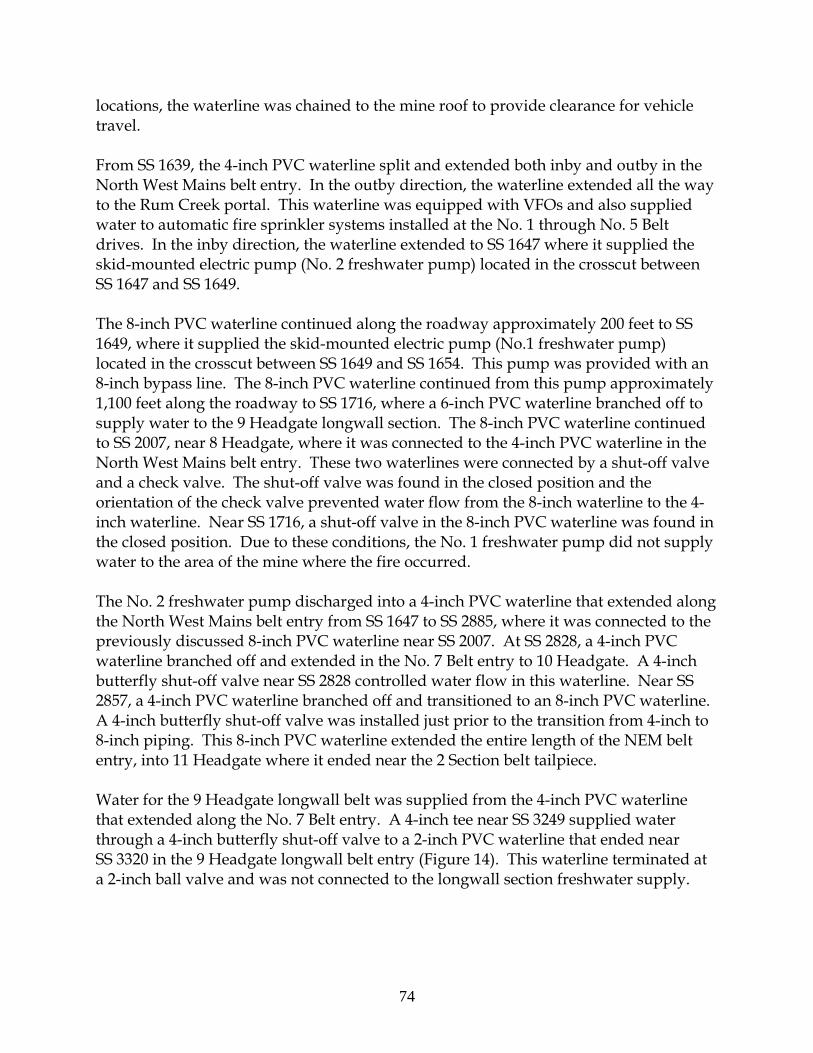
74
locations, the waterline was chained to the mine roof to provide clearance for vehicle travel. From SS 1639, the 4-inch PVC waterline split and extended both inby and outby in the North West Mains belt entry. In the outby direction, the waterline extended all the way to the Rum Creek portal. This waterline was equipped with VFOs and also supplied water to automatic fire sprinkler systems installed at the No. 1 through No. 5 Belt drives. In the inby direction, the waterline extended to SS 1647 where it supplied the skid-mounted electric pump (No. 2 freshwater pump) located in the crosscut between SS 1647 and SS 1649. The 8-inch PVC waterline continued along the roadway approximately 200 feet to SS 1649, where it supplied the skid-mounted electric pump (No.1 freshwater pump) located in the crosscut between SS 1649 and SS 1654. This pump was provided with an 8-inch bypass line. The 8-inch PVC waterline continued from this pump approximately 1,100 feet along the roadway to SS 1716, where a 6-inch PVC waterline branched off to supply water to the 9 Headgate longwall section. The 8-inch PVC waterline continued to SS 2007, near 8 Headgate, where it was connected to the 4-inch PVC waterline in the North West Mains belt entry. These two waterlines were connected by a shut-off valve and a check valve. The shut-off valve was found in the closed position and the orientation of the check valve prevented water flow from the 8-inch waterline to the 4-inch waterline. Near SS 1716, a shut-off valve in the 8-inch PVC waterline was found in the closed position. Due to these conditions, the No. 1 freshwater pump did not supply water to the area of the mine where the fire occurred. The No. 2 freshwater pump discharged into a 4-inch PVC waterline that extended along the North West Mains belt entry from SS 1647 to SS 2885, where it was connected to the previously discussed 8-inch PVC waterline near SS 2007. At SS 2828, a 4-inch PVC waterline branched off and extended in the No. 7 Belt entry to 10 Headgate. A 4-inch butterfly shut-off valve near SS 2828 controlled water flow in this waterline. Near SS 2857, a 4-inch PVC waterline branched off and transitioned to an 8-inch PVC waterline. A 4-inch butterfly shut-off valve was installed just prior to the transition from 4-inch to 8-inch piping. This 8-inch PVC waterline extended the entire length of the NEM belt entry, into 11 Headgate where it ended near the 2 Section belt tailpiece. Water for the 9 Headgate longwall belt was supplied from the 4-inch PVC waterline that extended along the No. 7 Belt entry. A 4-inch tee near SS 3249 supplied water through a 4-inch butterfly shut-off valve to a 2-inch PVC waterline that ended near SS 3320 in the 9 Headgate longwall belt entry (Figure 14). This waterline terminated at a 2-inch ball valve and was not connected to the longwall section freshwater supply.

75
Figure 14. 4-inch water valve (found in “off” position)
After the fire, MSHA investigators examined the area of the 4-inch butterfly valve where it connected to the 2-inch PVC waterline (SS 3249). This valve was visually examined and found in the closed position. It could not be determined when, or by whom, the valve had been closed. If this valve was closed at the time the fire started, water would not have been available in the 2-inch PVC waterline. This is the line Cabell initially attempted to use to fight the fire. After the fire, MSHA investigators found that much of the 2-inch PVC waterline along the 9 Headgate belt drive and takeup storage unit had been destroyed by the fire. Portions of the 4-inch PVC waterline along the No. 7 Belt in the immediate fire area had also been destroyed or severely damaged by the fire. Since this destruction occurred after the fire had become well established, it did not impact the initial efforts to fight the fire. However, it would have been necessary for mine rescue personnel to isolate this damaged piping prior to re-establishing the underground water supply to a usable condition for firefighting. Underground Freshwater Pumps Both underground freshwater pumps were constant-speed (3550 rpm), multi-stage centrifugal pumps driven by 60 hp, 3-phase electric motors. Both pumps were equipped with pressure-relief valves and check valves on the discharge side of the pumps, along with shut-off valves on both the suction and discharge sides. The relief valves were used to adjust the pump discharge pressure by re-circulating some of the water back to the suction side of the pump piping. The nameplates on both pumps indicated a rating of 450 gallons per minute (gpm) at a net discharge head of 422 feet (183 psi). The maximum discharge pressure was listed as 365 psi (843 feet of head).

76
Both pumps were powered by the underground electrical distribution system that also supplied power to the continuous mining machine sections (miner circuit). When power was shut off to the miner circuit, these pumps were de-energized and rendered inoperable. Water Supply and Mine Elevations Waterline elevations play an important role in the performance capability of any water system, especially for fire protection. Underground mine elevations were shown on mine maps. The elevation of the freshwater tank was provided by a representative of the mine operator. Based upon a comparison of the elevation of the freshwater tank with surface elevation contour lines shown on United States Geological Survey topographical maps (Logan Quadrangle), it was concluded that coal seam elevations shown on the mine maps were referenced to mean sea level (MSL). Information provided by the mine indicated that the bottom of the freshwater tank was at 814.8 feet MSL. The water level in the freshwater tank, when full, was approximately 836 feet MSL. With the pumps at an elevation of approximately 595 feet MSL, this would result in a maximum static head pressure underground of approximately 103 psi on the suction side of the pumps. In the North West Mains, the 4-inch PVC waterline reached an elevation of 836 feet MSL approximately one crosscut outby of SS 2826. Operation of the No. 2 freshwater pump was necessary to force water beyond this location because inby locations were above the freshwater tank elevation. A hydraulic elevation profile diagram of the water system is provided in Appendix U. Valved Firehose Outlets The valved firehose outlets (VFOs) typically consisted of 1-1/2-inch diameter steel pipe threaded into PVC couplings in the waterlines. The valves on these outlets were 1-1/2 inch brass ball valves with a short pipe nipple threaded into the discharge side of the valve. Each pipe nipple ended with an exposed male National Pipe Tapered (NPT) thread. Without special thread adapters, only firehoses equipped with National Pipe Straight Hose (NPSH) threaded couplings were compatible with these outlets. The VFOs in the 9 Headgate longwall belt drive and takeup storage unit area were not equipped with these adapters. Plastic caps or other methods of protecting the pipe threads were generally not provided on the open end of the VFOs. The spacing between some VFOs outside the fire area exceeded the 300-foot maximum allowed by § 75.1100-2(b). Firehoses and Connections Statements of two miners indicated that on separate occasions, they were not able to connect firehoses to the VFOs near the 9 Headgate longwall belt takeup storage unit.

77
Both a male and female hose coupling were recovered in the longwall belt drive area near the location of fire origin. These couplings were removed from a fire-damaged red polymeric coated firehose that was lying on the mine floor. The female coupling was found to be incompatible with the male 1-1/2 inch NPT threads of the VFO. However, this same female hose coupling readily connected to a male hose coupling cut with National Hose (NH) threads. The firehose Cabell attempted to use during the fire was red in color. However, it could not be determined if the couplings recovered during the investigation were from the same firehose Cabell attempted to use. Male NPT threads are the threads normally provided on mine water supply VFOs. In order to be compatible with the NPT threads on the outlets, each female firehose coupling must be cut with National Pipe Straight Hose threads (NPSH). The NH threads found on the recovered couplers are the threads normally used by local fire departments and are not compatible with mine firehose connections unless special adapters are used. Annual Functional Tests Annual functional tests of fire hydrants (referred to as valved firehose outlets in this report) and firehoses are required by § 75.1103-11. A record of these tests must be maintained by the mine operator for at least one year. Though requested, the mine operator did not produce records to document the required annual functional tests of fire hydrants and fire hoses. Adequate functional tests would have revealed the threads of the female coupling on the fire hose were not compatible with the male threads on the VFO. Longwall Belt Fire Protection Primary and secondary belt drives are required to be provided with automatic fire suppression systems as specified in § 75.1101. This protection can take the form of deluge-type water spray systems, high expansion foam systems, water sprinklers (a.k.a. fire sprinklers), or dry chemical systems. The areas requiring protection include at least 50 feet of upper and lower belt (i.e., 50 feet of belt-entry length) for fire resistant belt, the belt takeup, the belt discharge pulley, gear reducing unit, and electrical controls. Although § 75.1101-7(b) does not define the location of the 50 feet of belt required to be protected, guidance is provided in the MSHA Program Policy Manual. On September 30, 2004, MSHA issued Program Policy Letter (PPL) P04-V-05 indicating that MSHA considers belt takeup storage units to be a form of takeup and therefore were required to have automatic fire suppression by virtue of § 75.1101. Storage type takeup units are commonly found in longwall belt systems. PPL P04-V-05 was reissued as P06-V-05 on June 21, 2006.

78
At the Aracoma Alma Mine #1, wet pipe sprinkler systems protected the various belt drives. Pendent sprinklers were installed on threaded cast-iron pipe tees and spaced approximately seven to eight feet apart. The pipe tees were connected together utilizing ¾-inch diameter hydraulic hoses in lieu of rigid steel pipe. These hoses were rubber covered with internal steel braiding and an internal rubber liner. Each sprinkler system was typically provided with a shut-off valve, strainer, and flow switch. The extent of sprinkler protection for the longwall belt drive on the No. 9 Headgate panel is shown in Appendix V. These sprinklers only protected the immediate area of the belt drive and discharge pulley. The sprinklers for the drive area were connected to the 4-inch PVC waterline in the No. 7 Belt entry. This connection point was just inby the longwall belt discharge pulley near SS 3249, and consisted of a reducing tee to connect the 4-inch PVC waterline to a 1 ½ -inch ball valve controlling water supply to the ¾-inch sprinkler system hoses. After the fire, the 1-1/2-inch ball valve controlling water flow to the longwall belt drive sprinkler system was under debris from a roof fall. Because of this debris, along with the instability of the overhead mine roof, it could not be visually examined by MSHA investigators. Later, on May 17, 2006, during the recovery of this area, investigators from the WVMHS&T recovered this valve and took it into custody. On May 23, 2006, the investigators transferred custody of the valve over to MSHA. This valve was in the closed position at that time. The investigators from WVMHS&T reported that this was the position they had found the valve in when they initially recovered it. Although the outer jackets over the metal braiding of the hydraulic hoses on the system had been completely burned away, the remainder of the hose assembly components, including the steel braiding, pipe fittings, and remnants of the sprinklers were still visible. It could not be determined whether or not the system was operational prior to the fire. The majority of the sprinklers on the system were visible during the investigation. All of those observed had missing thermal elements, probably melted by the fire. Many also had the frames themselves partially eroded or melted away. An examination of the fire area also revealed that neither automatic fire sprinklers nor any other form of fixed fire suppression had been installed over the belt takeup storage unit. There was no evidence of sprinklers, hoses, pipes, or fittings anywhere along the belt takeup storage unit, including the end of the unit nearest the longwall section (Rear Frame Assembly). Interview statements also indicated that no fire suppression system was installed on the belt takeup storage unit as required. Conveyor Belt Flame Resistance Testing Flame testing of conveyor belting is conducted in accordance with § 18.65. Conveyor belt materials meeting the requirements of § 18.65 are accepted by MSHA as flame

79
resistant. All conveyor belts used in underground coal mines are required by § 75.1108 and § 75.1108-1 to meet these requirements. Two belt samples were obtained during the mine fire investigation. One belt sample was collected from the 72-inch wide No. 7 Belt and the second sample was collected from the 60-inch wide longwall belt. The longwall belt sample was collected near the belt takeup storage unit. Both samples were collected as close to the fire area as practical, but far enough away from the fire area that the samples had no visible signs of fire or heat damage On June 13, 2006, the two belt samples were visually examined and then subjected to flammability tests. Samples from both belts passed the criteria established for the flame test. Information relative to the belt and flame tests is included in Appendix W.
Area of Fire Origin and Flame Propagation Fire is a destructive process that often damages or destroys vital clues and evidence that would otherwise simplify determination of the fire cause. Hose streams and other fire fighting efforts can also sometimes destroy vital clues. Therefore, many factors must be considered in determining the cause of a fire. The fire at the Aracoma Alma Mine #1 on January 19, 2006, started in the 9 Headgate belt takeup storage unit area, specifically in the vicinity of the pulley carriage assembly (PCA). This conclusion was based upon both eyewitness interview statements and was confirmed by the accident investigation team. Determining the point of origin of any fire requires taking into account a number of factors. These factors include, but are not limited to, the following: 1) the dynamics of fire plumes and hot gas layers; 2) the physical arrangement and response-to-fire properties of all materials in the area; 3) the arrangement, or lack thereof, of any enclosure or construction features capable of impeding or encouraging fire spread; and 4) the extent and direction to which heat and smoke spread. In general, the established and proven practice for determining the origin of a fire is to start at the outer extent of fire damage and smoke spread, and follow the increasing intensity of fire damage toward the area or point of origin. This approach is applicable because the observed effects of fire intensify as one gets closer to the origin. Examples of where this approach requires modification include incendiary fires with multiple points of origin, and in fires that burn to completion where all combustibles are completely consumed. Although the fire was intense, not all combustibles were consumed, as evidenced by remnants of unburned and partially burned belt in the fire area.

80
Under conditions where a fire is beneath a level mine roof, and where there is 1) limited air movement from mechanical ventilation, 2) a lack of obstructions or barriers that would impede fire-driven air movement due to buoyancy effects, and 3) sufficient availability of combustible materials, fire spread would be expected to occur equally in all directions. However, in the area of the 9 Headgate longwall belt drive and takeup storage unit, a number of factors strongly influenced fire spread. These factors included the slope of the entry where the fire occurred, the effects of the missing stoppings, and the continuity of readily available combustibles along the longwall belt entry. These conditions significantly influenced the direction of fire spread. When combined with other specific observations, including damage to the belt structure, these conditions provided “vectors” that helped track the fire spread back to the area of origin. Observations Appendix X identifies the approximate extent of observed heavy soot deposits and the approximate extent of heavy thermal damage, much of it attributed to direct flame exposure and burning. Heavy soot deposits are the result of exposure to smoke for extended periods of time. However, smoke traveled beyond areas with heavy soot deposits, continuing downwind until it exited the mine. The most severe areas of fire damage occurred within the 9 Headgate longwall belt drive and takeup storage unit area and the adjacent area of the No. 7 Belt entry. Heavy soot deposits are the results of exposure to smoke for extended periods of time. However, smoke traveled beyond areas of heavy soot deposits downwind until it exited the mine. The suspended longwall belt structure between the PCA and the drive structurally failed and collapsed during the fire. The collapsed belt structure fell onto the mine floor or onto other materials below, including the mantrip parked in the roadway by Callaway. Heat from the fire caused the steel chains suspending this belt structure from the roof to stretch and break. Observations indicated the longwall belt entry from the PCA to the No. 7 Belt entry was exposed to intense flame. Inby the PCA, a nearly level soot line was visible, beginning at the mine floor, rising along the ribs of the sloped entry until it reached the mine roof near the Rear Frame Assembly (RFA) at the back of the takeup storage unit. Soot was not visible on the ribs below the level soot line. The soot line indicated the fire traveling toward the RFA was of limited intensity and did not travel toward the longwall section beyond the RFA. Fluorescent light fixtures vertically mounted on the upper portion of the rib along the takeup storage unit intersected this soot line. Above the soot line, damage to these fixtures indicated they had been exposed to substantial heat. The plastic lens portion of the fixtures above the soot line were melted or burned, and the metal cases had paint burned off or blistered. These observations provided strong evidence this soot layer

81
was part of a hot gas layer typically associated with a well established nearby flaming fire. Belt Entry Slope and Its Effect on Flame Propagation Two forms of combustion are recognized in the field of fire science. These are smoldering combustion, also known as surface burning, and flaming combustion. Flames are referred to as gas-phase combustion because the fuel participating in combustion is in the gas phase. This can be due either to the fuel’s natural gaseous state, or because the fuel was converted from a solid or liquid to the gas phase prior to entering the combustion zone. For liquids, this conversion process is normally vaporization; for solids, the process is normally pyrolysis. Flames represent the more efficient of the two forms of combustion and are readily capable of providing rapid rates of heat release. The very hot gases exiting the top of a flame are known as the fire plume. These hot gases travel upward due to their strong buoyant nature. The greater the heat release rate of the fire, the higher the velocities of the fire plume gases. The upward flow of the plume will continue until the plume is either cooled sufficiently by cooler surrounding air entrained in the plume as it rises, or until it hits a barrier to the upward movement, such as the mine roof in this instance. Generally, except for very small fires, fire plumes would have to travel many tens or even hundreds of feet vertically before sufficient air entrainment would cause sufficient plume cooling to prevent further upward travel. For practical purposes, cooling of the fire plume by air entrainment only stops plumes from rising in fires in open areas or in enclosures with very high ceilings. When upward plume flow is stopped because of barriers such as a mine roof, the hot gases turn and travel under the barrier. If the barrier is level, these gases tend to disperse in all directions equally. However, if the barrier is inclined, the buoyancy of the hot plume gases will drive the gases uphill under the barrier. Even a few degrees of incline can have a measurable effect on driving the plume uphill. At the Aracoma Alma Mine #1, the longwall belt entry inclined at approximately 7 degrees, from the PCA toward the longwall belt transfer point. This incline was sufficient to drive the plume and fire in this direction, including most of the hot gases. The incline of the belt entry strongly influenced the direction of fire gas travel and caused the fire to spread uphill and into the No. 7 Belt entry. A stopping, located between SS 3249 and SS 3236, prevented further spread uphill. The fire and smoke spread both inby and outby in the No. 7 Belt entry away from SS 3249. Although the No. 7 Belt entry, from SS 3249 toward 2 Section, was only slightly inclined, the missing stopping inby SS 3266 permitted the rising plume to enter the

82
2 Section primary escapeway. The No. 7 Belt entry from SS 3249 outby toward the No. 7 Belt drive was nearly level. Interview statements indicated airflow in the No. 7 Belt entry was limited and normally traveled from the drive toward the tail pulley. The level nature of the entry along with the direction of airflow caused most of the smoke to travel toward the 2 Section rather than toward the North West Mains. Point of Fire Origin Eyewitness interview statements placed the location where the fire was first observed near the mine floor, beneath the northeast side of the PCA. Expended portable fire extinguishers were found on the mine floor, on the side of the belt opposite from the location of first visible fire. Physical evidence indicated the point of fire origin was in the immediate area of the PCA, consistent with eyewitness interviews. The most intense burning occurred in the longwall belt entry between the PCA and the No. 7 Belt. Had the longwall drive entry been level, the point of fire origin would be expected to be located somewhere near the center of the intense burning area. However, the incline of the entry shifted the expected point of origin down hill, in the vicinity of the PCA. Continuity and Availability of Combustible Materials in the Area of Fire Origin In order for a fire to travel an extended distance between two points, combustible material must form a contiguous path between those points. In the longwall belt entry, a number of combustible materials existed to support and spread a well established fire. These included the coal rib and conveyor belt material, particularly the troughed belt loaded with coal and the return belt directly below. These two layers of belt extended the entire length of the longwall belt entry from the stage loader to the transfer point at SS 3249. In the belt drive and takeup storage unit area, these two belt layers were located in the upper portion of the entry. The entry had been mined to a height of about 12 feet in this area. The layers of belt near the roof became engulfed by hot gases from the fire plume, preheating the upper layers of belt ahead of the fire. This aided in the uphill fire spread and the growing intensity of the fire. A side view of the drive/takeup storage unit area is shown in Appendix D. Fire Spread Inby the Area of Origin Even though the two layers of upper belt extended inby to the longwall stage loader, fire travel in this direction was very slow compared to the uphill direction. As the fire burned and the fire plume drove the heat and smoke up hill, fresh air was needed to maintain the fire. This fresh air, which intensified air movement uphill into the fire,

83
came from lower elevations in 9 Headgate. Flame spread along the belt toward the longwall section against this uphill air movement resulted in what is known as opposed-flow flame spread. One indicator of opposed-flow flame spread is a sharp demarcation between burned and unburned material. This type of demarcation was observed on the belt between the PCA and the RFA. Opposed-flow flame spread impeded fire travel toward the longwall section. Once the fire in the area of the PCA had burned through the belt, the belt layers inby the PCA lost tension and fell into piles onto the takeup storage unit or onto the mine floor. This reduced the amount of belt surface exposed to burning, further impeding fire spread toward the longwall section.
Potential Ignition Sources
Determining the cause of the fire is a multi-step process. The first step is to combine knowledge of fire dynamics with observed patterns of fire damage and smoke travel to locate the immediate area of fire origin. Next, this area of origin is examined for all possible ignition sources. Types of ignition sources not found in the area can be eliminated as possible causes. By combining this process of elimination with an understanding of the response-to-fire characteristics of the combustible materials in the area of origin, the investigation can often reveal the most likely source of ignition and the chain of events leading to ignition. This investigation revealed the area of fire origin to be in the immediate vicinity of the PCA of the 9 Headgate longwall belt takeup storage unit. Physical evidence was consistent with interview statements. Both formed the basis for this conclusion.
Heat created by belt rubbing against the belt structure in the takeup storage unit was the ignition source for this fire.
Sources of Ignition Common sources of ignition considered in a fire investigation include cutting and welding operations, electrical related events, smoking, spontaneous ignition, and frictional heat. These potential ignition sources were evaluated in the area of fire origin during the investigation.
• Cutting and welding operations – Ignition sources in this category include open flames or molten sparks generated by torches or welders. Such flames or sparks can ignite nearby combustible materials, especially those of a lightweight nature such as paper, cardboard, coal dust, coal fines, or loose coal. These lightweight materials, when contaminated with grease or oil, become even more readily ignitable.

84
No equipment typically used for cutting or welding was found within the belt entry. Neither the interview statements nor the records of work assignments for January 19, 2006, indicated cutting or welding operations were conducted in the area during any shift on the day of the fire. Cutting and welding operations were determined not to be a likely source of the ignition.
• Electrical Circuits – Electrical related ignition sources include overloaded wiring
or equipment, short circuits, and loose or arcing connections. Such conditions can generate sufficient heat to ignite wire insulation or adjacent combustibles.
Electrical circuits were examined in the area of fire origin. The only circuits found were for light fixtures on the upper portion of the rib on the southwest side of the entry, and the cable bundle that contained the AMS and mine-wide telephone circuits. These circuits were damaged during the fire but were too far away from the area of fire initially observed by witnesses to have played a role in the ignition process. The fire was initially observed in the vicinity of the PCA on the opposite side of the entry from the lights and CO system cable. Electrical circuits were determined not to be the likely ignition source.
• Smoking– Discarded smoldering cigarettes or burning matches have been known
to result in ignition of combustible materials. Section 75.1702 prohibits the use or possession of smoking materials, including matches and lighters, inside an underground coal mine at any time. Mine operators are required to have a program in place to insure that smoking materials, matches, and lighters are not carried underground. This enforcement includes weekly searches on an irregular basis. During this investigation, no evidence was found, nor was any statement made by miners during interviews, implying any violation of these provisions. Smoking was determined not to be the likely ignition source.
• Spontaneous ignition – Some materials and/or chemicals are known to undergo
self-heating reactions that can, under some conditions, result in self-sustained heating and subsequent ignition of the materials or chemicals. This process is sometimes referred to as “spontaneous combustion.” This self-heating process is attributed to the exothermic oxidation of the material at elevated temperature. The lower the temperature at which the onset of oxidation occurs, the greater the propensity of the material is to self heat.
Some coals have shown a tendency to self-heat under certain conditions. Conditions affecting this tendency include the type of coal, its physical arrangement, and the amount of ventilation surrounding the coal. In terms of arrangement, small piles of coal, especially in ventilated areas, are far less likely

85
to undergo self-heating than larger, more extensive collections of coal, especially in poorly ventilated areas such as a gob. The results of laboratory analyses on coal samples collected from the Aracoma Alma Mine #1 strongly suggest that spontaneous ignition of coal accumulations in the No. 9 Headgate longwall takeup storage unit area was not the likely source of ignition for the fire on January 19, 2006. Details of the test results are provided in Appendix Y. Lubricating oils and greases were also present in the fire area. These greases and oils can be exposed to heat generated as part of their lubricating mission. Any tendency to oxidize at elevated temperatures would degrade their lubricating properties. Hence, these materials are chemically designed to resist oxidation under conditions of intended use and do not tend to undergo self-heating.
• Frictional heat – Two surfaces in contact with one another with at least one being
in motion, can create sufficient heat to ignite combustible materials in contact or in close proximity to one or both surfaces. Either surface may be combustible. In addition to generating heat, friction can also cause physical damage to one or both surfaces, resulting in generation of small fragments of the rubbed material. For example, a conveyor belt rubbing against another surface can create shavings and/or dust-like particles of belt material that could be more readily ignited due to the material’s high surface-area-to-mass ratio. When these rubbing conditions exist for a sufficient time, friction-generated shavings or particles can accumulate into a quantity of fuel easily ignited by sufficient friction generated heat.
A special case of frictional heating can occur when bearings on rotating shafts fail, causing metal to metal friction within the bearing. This can result in sufficient heat to cause the bearing materials to glow or even melt. Grease can boil out of the bearing housing and ignite upon contact with air. Burning grease may drop onto nearby easily ignitable materials. In some cases, molten metal from the bearing can also drip or fly from the bearing and come in contact with ignitable materials. Observations by MSHA accident investigators, reviews of the belt maintenance records, and interview statements indicated bearing failure was not a likely ignition source. Due to the roof fall that occurred in this area, prior to completing an examination of all belt takeup storage unit components, it was not possible to determine whether or not bearing failure on equipment had occurred on the PCA or adjacent drop-off carriage assemblies. It was not possible to recover this equipment for post-accident evaluations. Prior to the roof fall, MSHA investigators had not observed any indications of bearing failure in the fire area.
86
Interview statements revealed bearing temperatures in the longwall belt drive and takeup storage unit area had been checked four times during the shift prior to the accident. No temperatures were found that exceeded the normal operating range. The investigation uncovered substantial evidence that belt friction was a chronic problem within the belt takeup storage unit. This was indicated by piles of belt shavings found near the belt takeup storage unit, along with cuts and frayed edges of the conveyor belt itself. Notches cut into the structural steel of the belt takeup storage unit also indicated belt misalignment was a problem. Additionally, interview statements indicated that greasing of bearings was conducted frequently. Interview statements of the eyewitness who discovered the fire indicated the ignition source was friction between the belt and another surface. The friction created sufficient heat to ignite the initial fuel for the fire. A skewed drop-off carriage assembly moved the belt toward one side of the takeup storage unit. This caused frictional heating when the misaligned belt rubbed against any or all of the following: the bearing housing of the PCA; the frame of the PCA; or the frame of one of the drop-off carriage assemblies. Frictional heat caused by the belt rubbing against the structure of the takeup storage unit was determined to be the ignition source of this fire.
Belt Material Response-to-Fire Considerations Combustible materials have at least two separate and important response-to-fire characteristics frequently known as flame resistance and fire resistance. Flame resistance usually refers to the ease of ignition of a material, while fire resistance usually refers to a material’s burning characteristics after ignition occurs. Currently published fire science theories indicate that no correlation exists between these two properties. Materials difficult to ignite may burn intensely after ignition occurs, while materials easily ignited may continue to burn with difficulty. Because the longwall belt material passed the MSHA flame resistance test, it is very unlikely that frictional heating alone directly ignited this belt material into the observed rapidly growing flaming fire. This is because the frictional heating that occurred would have been a less intense heat source than the Bunsen burner flame used in the test. Because of the flame resistant nature of the belt, a stronger ignition source would have been necessary. This stronger ignition source most likely existed in the form of a larger fire impinging on the belt material. During the investigation, witness statements and observations revealed loose coal, coal dust, float coal dust, excessive grease build up, and belt shavings were present at various locations along the 9 Headgate longwall belt, beginning at the drive and continuing its entire length. These conditions were also

87
noted along other belts in the mine. Such easily ignitable combustible materials accumulating along the belt take up storage unit, once ignited, would have created a flaming fire capable of igniting the belt. Likely Initial Fuel Source Tests, observations, and interview statements indicated the ignition sequence involved frictional heat, developed between the belt and PCA structure, which ignited accumulations of combustibles, such as grease, loose coal, and coal dust, located on and below the PCA. These easily ignited accumulations quickly grew into the strong flaming fire needed to ignite the flame resistant belt. Once ignited, this belt quickly grew into an intense fire that resulted in generation of copious quantities of hot, dense, toxic smoke.
Additional Information The investigation revealed belt fires and other events that occurred in the weeks and months prior to January 19, 2006. Details surrounding these events indicated recurring problems. In addition, corporate communications regarding responsibilities and work assignments of miners were issued in October, 2005. Previous Belt Entry Fires and Other Incidents Interview statements revealed fires, hot belt rollers and bearings had previously been found in belt entries at Aracoma Alma Mine #1. At least two events developed into fires that required application of water and/or rock dust by miners to extinguish flames and/or glowing embers. Mine record books and a printout of the AMS event log provided additional information relative to these incidents. Fires occurred on December 23, 2005 at the 9 Headgate longwall belt takeup storage unit, and a second incident occurred on December 29, 2005, near the No. 5 Belt tailpiece. Mine officials either observed or were made aware of these two fires. A third fire reportedly occurred on 8 Headgate longwall belt, but the precise date could not be determined. It was not determined if mine management was aware of this event. An incident was identified in a review of the AMS event log in which multiple CO sensors sequentially indicated alert and alarm conditions on October 8, 2005. The cause of the alert and alarm conditions could not be determined, but the event seems to have occurred near the No. 4 Belt tailpiece. It was not determined if mine management was aware of this event. 8 Headgate Longwall Belt Takeup Storage Unit Fire One interviewed miner described an incident involving a fire that occurred while mining the No. 8 longwall panel. The incident reportedly occurred when a bearing in

88
the 8 Headgate longwall belt takeup storage unit caught fire. He heard the flames had reached the roof before the fire was extinguished using fire extinguishers. Miners were reportedly stationed in the area to monitor for rekindling after the fire was extinguished. While the miner did not remember the exact date on which the incident occurred, he estimated it to be during June or July of 2005, near the completion of mining in the No. 8 longwall panel. The CO Log book revealed numerous CO sensors indicated alert and alarm levels of CO during this period of time. However, it could not be determined if these CO sensors were located in the 8 Headgate longwall belt entry. The AMS event log provided by the mine operator did not include any information for the period between 14:30:25 on July 9, 2005, and 14:54:50 on July 22, 2005. No additional information concerning this incident was discovered by MSHA investigators. October 8, 2005, AMS Response A review of the AMS event log revealed a series of CO alert and alarm signals occurred at eleven CO sensor locations on October 8, 2005. This incident was not recorded in the CO Log Book. Interview statements indicated there was a heated tail roller which needed replaced at the No. 4 Belt tailpiece in the past, but there was no other testimony to support that a fire had occurred. Appendix Z shows the underground locations of the CO sensors involved. The information in the event log revealed the sequencing of the alert and alarm signals when the condition cleared at each sensor, and the maximum carbon monoxide concentration recorded by each CO sensor in an alert or alarm condition. Carbon monoxide was first measured at Sensor 90, located near the No.5 Belt drive. The CO levels at Sensor 90 reached the warning and alarm levels before other sensors detected sufficient concentrations to initiate warning and alarm signals. Warning and/or alarm conditions were recorded for consecutive CO sensors both inby and outby CO Sensor 90. Although CO Sensor 93 was located between Sensors 91 and 92 at the time of the accident, no alert or alarm signals were recorded for the sensor during the incident. However, no record of monitoring system communication with CO Sensor 93 was found in the AMS event log from October 3, 2005, thru October 28, 2005. The pattern of sensor alert and alarm signals is consistent with airflow carrying contaminants both inby and outby the source. The maximum CO concentration recorded during the event, 107 ppm, was at CO Sensor 90. The full-scale response for the CO sensors used in this AMS was 107 ppm. The maximum CO concentration recorded at each sensor decreased as the distance from CO sensor 90 increased. The pattern of CO concentrations at the sensors was consistent with dilution of contaminants caused by the mixing with air from adjacent common entries in the same air course and/or by mixing with air leaking into the belt air course from the adjacent intake air course.

89
The alert and alarm signals recorded in the printout of the AMS event log were not recorded in the CO Log Book. No record of this event was found in the Pre-shift - Onshift and Daily Report record book maintained for the belt examinations. Entries in the Pre-shift - Onshift and Daily Report record book maintained for the longwall section and mine production reports revealed coal was produced on day shift, the shift on which the incident was recorded, on the 9 Headgate longwall section. The 9 Headgate longwall section was located inby the sensors in which the alert and alarm signals occurred. Miners were working on the section at the time of the incident. No reference relative to the incident was made in the delays and remarks section of the longwall production report. The longwall production report indicated coal was being produced between 12:17 p.m. and 1:20 p.m. This was the period of time when the alert and alarm signals were generated by the AMS. This incident was not reported to MSHA. No additional information regarding this incident was discovered by MSHA accident investigators. It was not determined whether or not this incident was a fire.
Two other fires occurred in December of 2005, one of which was at the 9 Headgate takeup storage unit.
December 23, 2005, Fire Interview statements revealed the cause of an incident that occurred at the 9 Headgate longwall belt takeup storage unit on December 23, 2005, was similar to that which occurred on January 19, 2006. During the afternoon shift, dispatcher/AMS operator Brown observed alert and alarm signals from a CO sensor located near the 9 Headgate longwall belt drive. Brown contacted Conley, and asked him to investigate. Conley encountered smoke and found reddish-yellow colored embers in a pile of belt shavings on the mine floor beneath the belt in the 9 Headgate longwall belt takeup storage unit. Conley also found a drop-off carriage assembly in the belt takeup storage unit was skewed and had caused the belt to become misaligned. The misaligned belt appeared to have rubbed against the bearing housing and possibly something else. He believed the rubbing had caused shavings from the edge of the belt to accumulate and ignite. The belt was not operating at the time he arrived at the fire. He estimated the time required to extinguish the fire with water was approximately 30 minutes. During the incident, Conley noted there was insufficient water pressure to the area where the fire occurred. He also noted that the firehose he attempted to use was incompatible with the VFO in the fire area. Conley reported the event to Horton, who told him not to say the word “fire” over the mine phone, so that other miners would not be alarmed. Although Conley also reported the incident to his supervisor, it is uncertain whether mine management officials were made aware of these deficiencies. A review of the AMS event log for December 23, 2005, revealed a series of alert and alarm signals occurred at CO sensor locations during this incident. Alert and alarm

90
conditions were recorded for CO sensors located near the longwall belt takeup storage unit: first at CO Sensor 82, then at CO Sensor 81. CO Sensor 82 was located in the longwall belt entry between the belt takeup storage unit and the belt drive. CO Sensor 81 was located in the No. 7 Belt entry near the No. 7 Belt tail pulley. CO sensor locations are identified on the map in Appendix Z. The AMS event log indicated alarm conditions of CO Sensor 82 caused activation of the alarm unit on the longwall headgate. The pattern of sensor alert and alarm signals is consistent with airflow carrying contaminants from the belt takeup storage unit area outby to the No. 7 Belt entry and then inby past the No. 7 Belt tail pulley. The maximum CO concentration recorded during the event, 46 ppm, was at CO Sensor 82. The maximum CO concentration recorded at CO Sensor 81 was 11 ppm. The AMS event log indicated alert and alarm conditions lasted 41 minutes at Sensor 82. Entries in the Preshift-Onshift and Daily Report record book maintained for the longwall section and mine production reports revealed coal was produced on afternoon shift, the shift on which the incident occurred, on the 9 Headgate longwall section. The longwall production report for the afternoon shift on December 23, 2005, revealed the section crew departed from the longwall section at 9:35 p.m., before the time the AMS alarm was activated. As there were no miners on the longwall section, the performance of the activated alarm unit at the longwall headgate could not be verified. Entries in the Preshift-Onshift and Daily Report record book maintained for 2 Section revealed coal was produced on that section on the afternoon shift of December 23, 2005. The 2 Section was located inby the area where the sensors in which the alert and alarm signals occurred were located. Interview statements revealed the 2 Section crew was inby the area where the sensors in which the alert and alarm signals occurred during the incident were located. There was no entry in the Preshift - Onshift and Daily Report record book maintained for the belt examinations for an examination of the longwall belt during the day shift and afternoon shift on which the fire occurred. Although an entry was recorded in the CO Log Book regarding the fire, the record was not complete as required by § 75.351(o). December 29, 2005, Fire Interview statements and mine records revealed a fire occurred near the tailpiece of the No. 5 Belt on December 29, 2005. Brown contacted White and beltman Wyatt Robinson, who were both at the longwall belt electrical installation, and notified them that alarm signals had occurred at CO sensors located along the Nos. 5 and 6 Belts. The two miners traveled on foot to investigate the cause of the alarms.

91
Upon arriving at the No. 6 Belt drive area approximately 15 minutes later, the miners encountered smoke. The miners approached the fire through the smoke without donning SCSRs and found belt shavings, accumulated coal, and the adjacent coal rib burning near a bottom belt roller. The smoke was traveling inby toward the working sections. A bearing in the bottom roller, located a short distance outby the No. 5 Belt tailpiece, was believed to have been failing. One fire extinguisher and one bag of rock dust were used to extinguish the flames. However, one of the miners fighting the fire checked the visual display of a nearby CO sensor and found the carbon monoxide concentration was still above the warning level. Water was applied to the mine floor in the area to extinguish the remaining burning material. The failed bottom roller was removed and dropped into the wet material under the belt. White estimated the time required to fully extinguish the fire to be 30 minutes after discovery. Robinson estimated the time required to fully extinguish the fire to be 45 minutes after discovery. The alert and alarm levels were recorded for a period of 100 minutes during the fire. The belt was not stopped during the incident. David Meade, 003 Section foreman, was identified as also having assisted the two miners in extinguishing the fire. White informed Perry of the fire and that the hose clamps which secured the hose to the connector, failed during the application of water on the fire. Evidence of this fire was visible to MSHA personnel investigating the January 19, 2006, accident. Interview statements also indicated evacuation of the mine was considered by Meade before he spoke with Robinson. A review of the AMS event log for December 29, 2005, revealed a series of alert and alarm signals occurred at CO sensor locations during this fire. Alert and alarm conditions were recorded for CO sensors located in the North West Mains and the No. 7 Belt entries. The first alert signal occurred at CO Sensor 94, located in the No. 5 Belt entry outby the No. 5 Belt tailpiece. Signals were then recorded at CO Sensors 50, 51, 53, 80 and 81, which were inby the No. 5 Belt tailpiece. The AMS event log did not indicate an alert or alarm signal from Sensor 52, which was located between CO Sensors 51 and 53. Information in the AMS event log indicated communication problems with CO Sensor 52 during the incident. CO sensor locations are identified on the map in Appendix Z. There was no record in the AMS event log that indicated the alarm conditions of the six CO sensors caused activation of the alarm unit on the longwall headgate. The pattern of sensor alert and alarm signals is consistent with airflow carrying contaminants from outby the No. 5 Belt tailpiece to the end of the No. 6 Belt tailpiece and also from the No. 6 Belt entry along the No. 7 Belt to beyond the No. 7 Belt tail pulley. The maximum CO concentrations recorded during the fire were 107 ppm at CO Sensor 94, 107 ppm at CO Sensor 50, 68 ppm at CO Sensor 51, 56 ppm at CO Sensor 53, 42 ppm at CO Sensor 80, and 32 ppm at CO Sensor 81. No other CO sensors in the NEM belt entries detected alert or alarm levels of CO. No CO sensors located along the

92
longwall belt detected alert or alarm levels of CO. The indicated pattern of response and likely air flow direction is consistent with the response to the January 19, 2006, fire. Entries in the Pre-shift - Onshift and Daily Report record book maintained for the longwall section and mine production reports revealed coal was produced on afternoon shift, the shift on which the fire occurred, on the 9 Headgate longwall section. The longwall production report for the afternoon shift on December 29, 2005, also revealed coal was produced on the longwall section during the fire. The 9 Headgate longwall section was located inby the location of the fire. The lack of a record in the Pre-shift - Onshift and Daily Report record book maintained for 2 Section indicated coal was not produced on the afternoon shift on 2 Section. Although all mine record books for the time period in which the fire occurred were requested, the Pre-shift - Onshift and Daily Report record book maintained for the belt examinations was among the record books not provided to MSHA investigators by the mine operator. Although an entry was recorded in the CO Log Book regarding the fire, the record was not complete as required by § 75.351(o). This fire was not reported to MSHA. Corporate Communications The investigation revealed that on October 19, 2005, a memorandum was sent to all deep mine superintendents from Massey Energy, Inc. Chief Executive Officer (CEO), indicating that if they were asked “…to do anything other than run coal, (i.e. – build overcasts, do construction jobs, or whatever) you need to ignore them and run coal.” The first memo was addressed in a subsequent memo on October 26, 2005, in which the CEO clarified the company position that “…safety and S-1 is our first responsibility.” The latter memo stated that outby construction jobs needed to keep the mine safe and productive should be done, but every effort should be made to do them without taking people and equipment off of production sections. A copy of these memoranda can be found in Appendix AA. Lawrence Lester, Superintendent for Aracoma Alma Mine #1, declined to participate in a voluntary interview and, therefore, could not be questioned regarding these memos.
ROOT CAUSE ANALYSIS An analysis was conducted to identify the root causes that contributed to the accident. Removing or correcting these root causes would have averted the accident entirely or preventing the loss of life. Listed below are the causes identified during this analysis and their corresponding corrective actions to prevent a recurrence of the accident. In each case, no effective management system, policy or procedure was in place to assure compliance with the underlying regulations and safe mining practices.

93
Root Cause: The dispatcher/AMS operator who was on duty on the afternoon shift of January 19, 2006, was not properly trained. Corrective Action: The dispatcher/AMS operator received proper training on February 24, 2006, regarding firefighting procedures, emergency evacuation procedures, and the mine ventilations system, and proper responses to alert and alarm signals generated by the AMS. Root Cause: The location of all personnel doors in stoppings along the 2 Section escapeways were not clearly marked so the doors could be easily identified by anyone traveling in those escapeways. Corrective Action: The location of all personnel doors were clearly marked to identify all personnel doors in stoppings along primary and alternate escapeways such that doors can be easily identified by anyone traveling in the escapeways. Management developed a program to inform miners of the location of new doors installed or changes to existing doors along their respective escape routes. Root Cause: No CO alarm unit was installed on 2 Section to provide miners with automatic notification of CO alarm signals from outby sensor locations. Corrective Action: A CO alarm unit was installed on 2 Section to provide miners with automatic notification. Mine management must properly install and maintain the AMS in compliance with the requirements § 75.351. Root Cause: The mine operator failed to identify the absence of an alarm unit on 2 Section during visual examinations of the AMS on each production shift. Corrective Action: The mine operator retrained persons responsible for the examinations of the AMS to assure they are properly trained and familiar with the requirements of § 75.350, § 75.351, and § 75.352. Root Cause: The AMS operator on duty on the afternoon shift of January 19, 2006, failed to promptly notify the appropriate personnel that an alarm signal had been generated. Corrective Action: The dispatcher/AMS operator received proper training on February 24, 2006, regarding firefighting procedures, emergency evacuation procedures, and the mine ventilations system, and proper responses to alert and alarm signals generated by the AMS. Root Cause: Mine examiners did not identify existing hazardous conditions. Corrective Action: Miners and examiners were retrained to ensure that all hazardous conditions are addressed and appropriate corrective actions taken, regardless of when

94
the hazards are detected or by whom. Mine examiners must be equipped with and use equipment, including anemometers, chemical smoke, and gas detectors necessary to properly conduct examinations. Examiners must be properly trained to conduct these critical mine examinations and properly record the results of the examinations into the appropriate record books. Root Cause: The primary escapeway provided for 2 Section was not separated from the No. 7 Belt entry in the NEM inby the No. 7 Belt tail pulley. Corrective Action: Ventilation controls were constructed to separate the primary escapeway for 2 Section from the No. 7 Belt entry in the NEM inby the No. 7 Belt tail pulley. Mine management must ensure that permanent ventilation controls are properly installed and maintained to provide separation between belt entries and primary escapeways. Root Cause: Adequate escapeway drills were not conducted as required. Corrective Action: Management initiated a program to ensure that escapeway drills are conducted as required. Management must ensure that all miners have proper training at the required intervals and are familiar with escapeways from each working section to the surface. Mine management must also ensure escapeway drills are properly rotated between primary and alternate escapeways. Root Cause: Combustible materials, in the form of grease, oil, coal dust, float coal dust, coal fines, and loose coal spillage, were allowed to accumulate in the area of the 9 Headgate belt takeup storage unit. Corrective Action: The materials that remained after the fire were cleaned. Mine management must ensure that accumulations of combustible materials in underground belt entries are removed promptly. A program for regular cleanup and removal of accumulations of combustible materials must be established and maintained. Root Cause: A shut off valve was in the closed position, preventing water flow into the 2-inch diameter water supply line installed parallel to the 9 Headgate longwall belt. Corrective Action: Mine management has repaired the water supply system. Mine management must ensure that an adequate water supply is provided at all times. Root Cause: Threads of female couplings on the firehose first obtained for firefighting at the 9 Headgate longwall belt drive area were not compatible with the threads of male pipe of the valved firehose outlet. Corrective Action: Mine management has installed firehoses and firehose outlets that have compatible fittings. Mine management must ensure that adequate firefighting
95
equipment is provided along the belt. The threads of couplings and nipples must be compatible so that firehoses can be quickly connected to valved firehose outlets. Root Cause: The operator failed to install a fire suppression system that provided coverage over the electrical motors, belt takeup storage unit, gear reducing unit, and the electrical controls at the No. 9 Headgate longwall belt takeup storage unit. Corrective Action: Mine management expanded the fire suppression system to provide coverage over the electrical motors, belt takeup storage unit, gear reducing unit, and the electrical controls at the No. 9 Headgate longwall belt takeup storage unit. Mine management must ensure that fire suppression systems are provided and maintained where required. Root Cause: The operator failed to conduct adequate examinations of fire suppression systems and firefighting equipment. Corrective Action: Mine management conducted training that stressed the identification and correction of hazardous conditions and other conditions that would impair the effectiveness of fire suppression systems and firefighting equipment. Mine management and persons conducting examinations, and functional tests of fire suppression systems and firefighting equipment must be trained and knowledgeable in the requirements of Sections 75.1101 and 75.1103, and MSHA PPL No. P06-V-5. Root Cause: The mine map was not kept up-to-date by temporary notations to depict the permanent ventilation controls constructed and/or removed in the NEM. Corrective Action: The mine map was properly updated. Mine management must ensure an accurate and up-to-date map of the mine be maintained, including but not limited to required temporary notations. Mine management and persons assigned the responsibility for maintaining the required map should be trained and knowledgeable in the requirements of Subpart M-Maps. Root Cause: Mine management failed to initiate and conduct an immediate evacuation on January 19, 2006, when a fire at the 9 Headgate longwall belt takeup storage unit presented an imminent danger to the miners. Corrective Action: Mine Management must ensure that miners are withdrawn to a safe location when there is a mine emergency which presents an imminent danger to miners due to a fire. Root Cause: The mine operator failed to maintain the 9 Headgate longwall belt in a safe operating condition and did not remove it from service as required.

96
Corrective Action: Mine management must identify and promptly correct hazardous conditions on mobile and stationary equipment. Mine management must remove equipment in unsafe operating condition from service immediately.

97
CONCLUSION On January 19, 2006, carbon monoxide sensors in the 9 Headgate longwall belt unit area of Aracoma Alma Mine #1 detected alarm levels of CO at approximately 5:14 p.m. Twenty-nine underground miners were working at the time. During the evacuation process, two of the 12 miners from 2 Section became separated from the remainder of the crew when dense smoke was encountered. Initial attempts to locate the missing miners and extinguish the fire were unsuccessful. Two miners died as a result of the fire. The fire was eventually brought under control by mine rescue teams and the deceased miners were found on January 21, 2006. The fire occurred as a result of frictional heating when the longwall belt became misaligned in the 9 Headgate longwall belt takeup storage unit. This frictional heating ignited accumulated combustible materials. The required fire suppression system was not installed in the area where the fire occurred. Water was turned off to the firefighting waterline in the area, and firehoses could not be used. The fire extinguishers expended did not extinguish the fire. Stoppings that were required to maintain separation between the No. 7 Belt entry and the primary escapeway for 2 Section had previously been removed. Examinations of the mine were inadequate and failed to identify the lack of separation between the primary escapeway and belt air course. In addition, examinations of safety systems failed to identify deficiencies which contributed to the severity and extent of the mine fire. Airflow carried the smoke from the fire to the No. 7 Belt entry and then into the primary escapeway for 2 Section through the openings created by the stoppings that had been previously removed. Mine management did not immediately notify nor did they immediately withdraw miners from the affected areas (2 Section and the longwall section) to a safe location following the initial CO alarm signal from the AMS. At 5:39 p.m., the dispatcher attempted to alert the 2 Section crew by remotely stopping the 2 Section belts. At approximately 5:42 p.m., the 2 Section foreman called the dispatcher regarding the belt stoppage, and was instructed by the dispatcher and the afternoon shift mine foreman to evacuate. Two miners became separated from the other 2 Section miners during the evacuation and perished. The remaining twenty-seven miners working underground escaped safely.

98
ENFORCEMENT ACTIONS
A 103(k) order was issued to ensure the safety of all persons until an investigation was completed and the area and equipment deemed safe. The following violations were deemed to have contributed to the accident. Other violations deemed not to have contributed to the cause or severity of the accident were cited separately and are not addressed in this report. 104(d)(2) Order No. 7435530 75.380(g) S&S Reckless Disregard The primary escapeway provided for the 2 Section was not separated from the No. 7 Belt conveyor entry in the North East Mains inby the No. 7 Belt conveyor tail pulley. This condition was created prior to November 2005, when one or more permanent stoppings that provided separation between the No. 7 Belt conveyor entry and the primary escapeway in the North East Mains were removed. This lack of separation between the primary escapeway and the belt conveyor entry allowed smoke and carbon monoxide gas to inundate the primary escapeway used by the miners during the evacuation from 2 Section on January 19, 2006. Smoke from the fire adversely impacted the ability of miners from 2 Section to escape, resulting in two fatalities. 104(d)(2) Order No. 7435531 75.383 S&S Reckless Disregard Adequate escapeway drills were not conducted as required. The frequency of the escapeway drills did not always meet the 90-day period requirement during the 12 months prior to January 19, 2006. In addition, the 90-day practice escapeway drills that had been conducted during the 12 months prior to January 19, 2006, were not always rotated between the primary and alternate escapeways. Mine records indicate that not all miners working on 2 Section on January 19, 2006, participated in a practice escapeway drill in the 90 days preceding the accident. Moreover, the practice escapeway drills that were conducted were inadequate for the following reasons:
1. Contrary to mine records, miners from 2 Section did not travel the primary escapeway in its entirety to the surface during required 6-week escapeway drills. The required 6-week escapeway drills conducted in the primary escapeway consisted of traveling in a rubber-tired diesel mantrip from the section in the North East Mains roadway, through the equipment doors at the 9 Headgate longwall belt drive area, rather than the designated route over the intake overcast at Survey Station 3221.

99
2. Miners traveled through areas not clearly marked as escapeways during escapeway drills. The escapeways from 2 Section were not clearly marked throughout the North East Mains. The amber reflective tags used to mark the alternate escapeway route did not clearly show the route and direction of travel from the section to the surface. Green reflective tags, used to mark the primary escapeway route, were located in multiple parallel mine entries between 2 Section and the North West Mains. In addition, not all changes in direction of travel in the escapeways were clearly marked.
3. Miners were not afforded the opportunity to become familiar with the location of
all personnel doors in stoppings along the 2 Section escapeways during escapeway drills. The personnel door used by the 2 Section crew during their escape from the mine was located in North East Mains between SS 3224 and SS 3230 in the stopping that separated the primary and alternate escapeways. The location of this personnel door was not marked so it could be easily identified by anyone traveling in the escapeway.
4. The escapeway maps kept on 2 Section and the longwall working sections and
the escapeway map posted at the surface location where miners congregate were not accurate nor kept up-to-date. The mine workings shown on the maps were not up-to-date to show the current location of 2 Section and the designations of the respective escapeways on the maps did not accurately depict the marked underground routes of travel.
The failure to conduct adequate escapeway drills as required contributed to the inability of the victims to successfully evacuate the mine on January 19, 2006. 104(d)(2) Order No. 7435109 75.333(c)(2) S&S High Negligence The location of all personnel doors in stoppings along the 2 Section escapeways were not clearly marked so that the doors could be easily identified by anyone traveling in the escapeways. The personnel door used by the 2 Section crew during their escape from the mine was located in North East Mains between SS 3224 and SS 3230 in a stopping that separated the primary and alternate escapeways. The location of this personnel door was not marked. The failure to clearly mark the location of all personnel doors in stoppings along primary and alternate escapeways so that the doors could be easily identified by anyone traveling in the escapeways contributed to the inability of the victims to successfully evacuate the mine on January 19, 2006.

100
104(d)(2) Order No. 7435525 75.360(b)(9) S&S Reckless Disregard Preshift examinations required at the location of the underground electrical installations for the 9 Headgate longwall belt, south of SS 3266, were not adequate. The examinations failed to identify the lack of a properly constructed airlock intended to separate the 2 Section primary escapeway from the No. 7 Belt conveyor entry. A permanent stopping, located immediately adjacent to the North East Mains roadway South of SS 3266 was removed a significant period of time prior to January 19, 2006, reportedly to reduce heat in the crosscut where the power boxes were installed. The removal of this stopping, in conjunction with the open crosscuts along the North East Mains roadway between 9 Headgate and 9 Tailgate, resulted in a lack of separation between the 2 Section primary escapeway and the No. 7 Belt conveyor entry. This lack of separation between the primary escapeway and the belt conveyor entry allowed thick smoke and carbon monoxide gas to inundate the primary escapeway used by the miners during the evacuation from 2 Section on January 19, 2006. Due to reduced visibility caused by the thick smoke, two miners were separated from the section crew and unable to escape. 104(d)(2) Order No. 7435110 75.360(b)(10) S&S Reckless Disregard Preshift examinations required at the location where miners were scheduled to install belt structure inby the No. 7 Belt conveyor tail pulley were inadequate. The stopping between SS 3266 and 3332, in North East Mains had been removed to facilitate extension of the No. 7 Belt conveyor structure. The stopping was necessary to separate the No. 7 Belt conveyor from the primary escapeway for 2 Section. Corrective actions were not taken for the hazardous condition created by the absence of stoppings necessary to provide separation between the primary escapeway for 2 Section and the No. 7 Belt conveyor Entry. This lack of separation between the primary escapeway and the belt conveyor entry allowed thick smoke and carbon monoxide gas to inundate the primary escapeway used by the miners during the evacuation from 2 Section on January 19, 2006. Due to reduced visibility caused by the thick smoke, two miners were separated from the section crew and unable to escape. 104(d)(2) Order No. 7435108 75.360(b)(10) S&S Reckless Disregard The mine operator failed to conduct an adequate preshift examination of the No. 7 Belt conveyor for the day shift on January 19, 2006. This examination was also intended to satisfy the requirements of 75.362 (b).

101
The belt examiner failed to identify, record, and correct that the No. 7 Belt conveyor was not separated from the primary escapeway for 2 Section. Further, the last record of an examination of the No. 7 Belt conveyor was not signed or initialed by the examiner. The examination was not complete, and hazardous conditions that were determined to have existed at the time of the examination were not recorded. The examination record indicated air was moving in the right direction with a velocity greater than 50 fpm. However, the belt examiner stated he did not make airflow direction determinations, or air velocity measurements, and was unable to identify the proper airflow direction in the No. 7 Belt conveyor entry. The stopping was one of those necessary to provide separation between the 2 Section primary escapeway and the No. 7 Belt conveyor entry. This lack of separation allowed smoke and carbon monoxide gas to inundate the primary escapeway used by the miners during the evacuation from 2 Section on January 19, 2006. Smoke from the fire adversely impacted the ability of miners from 2 Section to escape, resulting in two fatalities. 104(d)(2) Order No. 7435526 75.362(b) S&S Reckless Disregard The mine operator failed to conduct adequate on-shift examinations of the longwall belt conveyor for the day shift on January 19, 2006. The following hazardous conditions were not identified by the mine examiner:
1. Accumulations of combustible material were present in the form of grease, oil, coal dust, coal fines, and loose coal spillage at numerous locations along the approximate 2,000 feet length of the 9 Headgate longwall belt conveyor;
2. Damaged bottom rollers, bottom rollers on the ground with indications they had been rotating in combustible material on the mine floor, and damaged top rollers;
3. Damaged and missing trip latch lever posts and damaged drop-off carriage assembly trip latch levers that affected positioning of the drop-off carriage within the 9 Headgate longwall belt takeup storage unit;
4. No fire suppression system of any type, which would actuate in the event a rise in temperature, was provided for the belt takeup storage unit and electrical components; and
5. Fire hose outlet valves near the longwall belt conveyor tailpiece were not provided with handles to actuate.
There were also several indications of prolonged operation of the longwall belt conveyor system while the belt was misaligned, including:
1. Damaged belt hangers, some partially cut through and others severed from prolonged rubbing from misaligned belt;

102
2. Damaged belt takeup storage unit frame components, partially cut through from prolonged rubbing of misaligned belt;
3. Severed strips of belt on the mine floor and hanging on belt structure; 4. Lengths of partially severed strips of belt; 5. Shavings of belt on the mine floor; 6. Belt cord fibers wrapped around belt roller components; and 7. Extended lengths of belt with frayed edges.
Further, the last record of an examination of the 9 Headgate longwall belt conveyor was not signed or initialed by the examiner. The examination was not complete and hazardous conditions that were determined to have existed at the time of the examination were not recorded. Although the examination record indicated air was moving in the right direction with a velocity greater than 50 fpm, the belt examiner stated he did not make airflow direction determinations or air velocity measurements and was unable to identify the proper airflow direction in the longwall belt entry. Required mine examinations were routinely conducted by certified examiners who were not equipped with an MSHA approved gas detector capable of determining oxygen deficiency and methane concentrations. Based on these conditions, the longwall belt conveyor should have been removed from service by the examiner. These conditions were obvious and located in the areas traveled by mine examiners. Many of these conditions contributed to the severity and extent of the mine fire on January 19, 2006, which ultimately resulted in the two fatalities. 104(d)(2) Order No. 7435527 75.363 S&S Reckless Disregard Not all hazardous conditions were being posted, corrected, and recorded. Although mine management was aware of hazardous conditions, effective corrective actions were not taken. The record maintained by the operator for the purpose of recording results of examinations for hazardous conditions indicated that actions were not taken to correct the hazardous conditions listed regarding the 9 Headgate longwall belt conveyor from January 2, 2006 to January 19, 2006. Although hazardous conditions, such as the need for additional cleaning and rock dusting, were noted in the record book, no corrective actions were listed for 38 of the 56 examinations. The corrective actions listed for the remaining 18 examinations were inadequate. Mine record books indicated a history of hazardous conditions, yet mine management failed to properly address the conditions. Moreover, results of the two examinations on January 19, 2006, prior to the accident indicate the 9 Headgate longwall belt conveyor needed to be cleaned and dusted. No corrective actions were listed in the record and a physical examination of the 9

103
Headgate longwall belt conveyor during the accident investigation indicated that appropriate actions had not been taken to correct the conditions. In addition, corrective actions were not taken for the hazardous condition created by the absence of stoppings necessary to provide separation between the primary escapeway for 2 Section and the No. 7 Belt conveyor entry. A permanent stopping, located immediately adjacent to the North East Mains roadway South of SS 3266 was removed a significant period of time prior to January 19, 2006, reportedly to reduce heat in the crosscut where the power boxes were installed. The absence of this stopping resulted in the lack of a properly constructed airlock intended to separate the 2 Section primary escapeway from the No. 7 Belt conveyor entry. Another stopping located between SS 3266 and SS 3332 in North East Mains had been removed at the direction of mine management personnel to facilitate extension of the No. 7 Belt conveyor structure. This stopping was necessary to separate the No. 7 Belt conveyor entry from the primary escapeway for 2 Section. These conditions were obvious and located in the areas traveled by mine examiners. These conditions contributed to the severity and extent of the mine fire on January 19, 2006, which ultimately resulted in the two fatalities. 104(d)(2) Order No. 6643276 75.364(b)(1) S&S Reckless Disregard Adequate weekly examinations of the entire No. 7 Belt air course were not conducted from November 1, 2005, to January 19, 2006. The examinations failed to identify the lack of separation between the No. 7 Belt air course and the 2 Section primary escapeway. This condition was determined to have existed prior to November 2005, when a permanent stopping located between SS 3266 and SS 3332 in North East Mains had been removed to facilitate extension of the No. 7 Belt conveyor structure. Examination records which specifically identified that the No. 7 Belt air course was examined in its entirety were not provided by the mine operator. By definition, the belt air course includes the entry in which the belt is located and any adjacent entry(ies) not separated from the belt entry by permanent ventilation controls, including any entries in series with the belt entry, terminating at a return regulator, a section loading point, or the surface. This lack of separation between the No. 7 Belt air course and the 2 Section primary escapeway in North East Mains allowed thick smoke and carbon monoxide gas to inundate the primary escapeway used by the miners during the evacuation from 2 Section on January 19, 2006. Due to reduced visibility caused by the thick smoke, two miners were separated from the section crew and were unable to escape.

104
104(d)(2) Order No. 7435528 75.364(b)(5) S&S Reckless Disregard Weekly examinations of the primary escapeway provided for 2 Section conducted from November 1, 2005 to January 19, 2006, were not adequate. The examinations failed to identify the lack of separation between the 2 Section primary escapeway and the No. 7 Belt conveyor entry. This condition was determined to have existed prior to November 2005, when a permanent stopping, located south of SS 3266, was removed at the 9 Headgate longwall dual switch house electrical installation. Another stopping located between SS 3266 and SS 3332 in North East Mains had been removed at the direction of mine management personnel to facilitate extension of the No. 7 Belt conveyor structure. This stopping was necessary to separate the No. 7 Belt conveyor entry from the primary escapeway for 2 Section. The examination also failed to identify the following: the lack of a clearly marked primary escapeway to show the route and direction of travel from 2 Section to the surface; the location of all personnel doors along the primary escapeway so that the doors could be easily identified by anyone traveling in the escapeway; and holes in numerous stoppings located between the 2 Section primary escapeway and the North East Mains No. 1 Belt conveyor entry that compromised the separation between these entries. This lack of separation between the primary escapeway and the belt conveyor entry allowed thick smoke and carbon monoxide gas to inundate the primary escapeway used by the miners during the evacuation from 2 Section on January 19, 2006. Due to reduced visibility caused by the thick smoke, two miners were separated from the section crew and unable to escape. 104(d)(2) Order No. 7435533 75.1100-1(a) S&S High Negligence The 2-inch diameter water supply line installed parallel to the 9 Headgate longwall belt conveyor pursuant to 30 CFR § 75.1100-2(b) was not capable of delivering 50 gallons of water per minute at a nozzle pressure of 50 pounds per square inch. An eye witness statement indicated while attempting to fight the fire, the fire hose outlet valve located near the belt conveyor takeup storage unit was opened and no water was produced. The absence of water to fight the fire directly impacted the ability to control and extinguish the fire on January 19, 2006. The condition contributed to the severity, extent, and magnitude of the mine fire, which ultimately resulted in the two fatalities. 104(d)(2) Order No. 7435534 75.1100-2(b) S&S Reckless Disregard Adequate fire fighting equipment was not provided for the 9 Headgate longwall belt conveyor. The threads of the female coupling of the fire hose were not compatible with the threads of the male pipe of the fire hose outlet valve.

105
The lack of compatible fire fighting equipment resulted in the failure to extinguish the fire on January 19, 2006. This contributed to the severity, extent, and magnitude of the mine fire, which ultimately resulted in the two fatalities. In addition, valuable time was lost during the initial effort to connect incompatible firefighting hoses to fire hose outlet valves. This further delayed the evacuation of the miners from 2 Section. 104(d)(2) Order No. 7435535 75.1101-8(a) S&S Reckless Disregard The mine operator failed to install the water sprinkler system in accordance with 30 CFR § 75.1101-8(a). The water sprinkler system did not provide coverage over the electrical motors, belt takeup storage unit, gear reducing unit, and the electrical controls at the No. 9 Headgate longwall belt conveyor takeup storage unit. The fire initiated in the belt takeup storage unit. The absence of an adequate and complete water sprinkler system resulted in the failure to extinguish the fire on January 19, 2006. The condition contributed to the severity, extent, and magnitude of the mine fire, which resulted in the two fatalities. 104(d)(2) Order No. 7435536 75.1101-11 S&S Reckless Disregard The mine operator failed to conduct adequate weekly examinations of the water sprinkler system for the 9 Headgate longwall belt conveyor belt drive, takeup storage unit, electrical controls, and gear-reducing unit. The electrical components and belt take-up storage unit were not provided with a fire suppression system which would activate in the event a rise in temperature occurred at this location. These hazardous conditions were not identified and recorded at the time of the examination. Corrective action was not taken to address the condition. Proper examinations would have revealed the absence of an adequate and complete water sprinkler system. This resulted in the failure to extinguish the fire on January 19, 2006. The condition contributed to the severity, extent, and magnitude of the mine fire, which resulted in the two fatalities. 104(d)(2) Order No. 7435522 75.1103-11 S&S Reckless Disregard Records were not produced by the mine operator to document required annual functional tests of fire hydrants and fire hoses in the mine. Adequate functional tests would have revealed the threads of the female coupling of the fire hose were not compatible with the threads of the male pipe of the fire hose outlet valve.

106
Valuable time was lost during the initial effort to connect incompatible firefighting hoses to fire hose outlet valves. This further delayed the evacuation of the miners from 2 Section. The lack of compatible fire fighting equipment resulted in the failure to extinguish the fire on January 19, 2006. This condition contributed to the severity, extent, and magnitude of the mine fire, which ultimately resulted in the two fatalities. This same condition existed at the same location during a fire on December 23, 2005. 104(d)(2) Order No. 7435523 75.351(c)(4) S&S Reckless Disregard The Atmospheric Monitoring System did not automatically provide visual and audible signals at all affected working sections when the carbon monoxide concentration at CO sensors reached alarm level. No carbon monoxide alarm unit was installed at a location where it could be seen or heard by miners on 2 Section to provide automatic notification of carbon monoxide alarm signals from outby sensor locations. The affected working sections during the fire that occurred on January 19, 2006, included both 2 Section and 9 Headgate longwall section. The failure to automatically provide visual and audible signals on 2 Section significantly contributed to the delay in the notification and withdrawal of miners who were working on 2 Section when a belt fire occurred on January 19, 2006. 104(d)(2) Order No. 7435521 75.351(n)(1) S&S Reckless Disregard Adequate visual examinations of alarms and sensors used to detect carbon monoxide were not conducted each production shift on 2 Section. An adequate visual examination would have revealed there was no alarm unit installed on 2 Section to automatically provide visual and audible signals that could be seen and heard by miners on the section when carbon monoxide concentrations reached alarm level. The failure to automatically provide visual and audible signals on 2 Section significantly contributed to the delay in the notification and withdrawal of miners who were working on 2 Section when a belt fire occurred on January 19, 2006. 104(d)(2) Order No. 7435529 75.352(a) S&S High Negligence The Atmospheric Monitoring System (AMS) operator who was on duty when the mine fire occurred on January 19, 2006, did not promptly notify the appropriate personnel that an alarm signal had been generated. Similar actions were taken by the AMS operator on duty on December 23, 2005, when a fire occurred at the 9 Headgate longwall belt conveyor takeup storage unit. The AMS

107
operator notified a miner to investigate the source of the alarms, but did not notify appropriate personnel of alarm signals. In these two fire events, the AMS operator on duty failed to promptly notify appropriate personnel of alarm signals. This was supported by the fact that miners on affected sections were not withdrawn to a safe location on these dates. This lack of prompt notification significantly contributed to the delay of the withdrawal of the miners on 2 Section and 9 Headgate longwall section to a safe location on January 19, 2006. This delay endangered miners due to the life-threatening and deteriorating circumstances, and contributed to the inability of the two victims to escape the mine. 104(d)(2) Order No. 7435524 75.352(c)(2) S&S High Negligence On January 19, 2006, an underground mine fire occurred at the 9 Headgate longwall belt conveyor takeup storage unit. Atmospheric Monitoring System (AMS) alarm signals were indicated for carbon monoxide sensors 81 and 82. Persons in the affected areas were not notified of these alarms and were not promptly withdrawn to a safe location identified in the mine operator’s Emergency Evacuation and Firefighting Program of Instruction. The affected working sections during the fire that occurred on January 19, 2006, included both 2 Section and 9 Headgate longwall section. Two other fires occurred at this mine (December 23, 2005, 104(d)(2) Order No. 6643221, and December 29, 2005, 104(d)(2) Order No. 6643222) during which carbon monoxide sensors activated AMS alarm signals in the dispatcher’s office on the surface. In both cases, the miners in the affected areas of the mine were not notified of the alarms and were not withdrawn to a safe location. The mine operator’s repeated lack of proper response to the carbon monoxide alarm signals is an indication of an attitude of indifference to the requirements of 30 CFR § 75.352(c)(2). The delay in notification and failure to promptly withdraw miners contributed to the inability of the two victims to escape the mine on January 19, 2006. 104(d)(2) Order No. 7435538 75.1501(b) S&S Reckless Disregard Mine management failed to initiate and conduct an immediate evacuation of the miners working on 2 Section and the longwall when the conditions at the 9 Headgate longwall belt takeup storage unit presented an imminent danger to the miners. Mine management personnel were aware of a fire at the 9 Headgate longwall belt takeup storage unit. The responsible person, designated by the operator for that shift, was made aware of the fire by the belt examiner immediately upon discovery, and failed to initiate and conduct an immediate mine evacuation. The delay in conducting an immediate mine evacuation contributed to the inability of the two victims to escape the mine on January 19, 2006.

108
104(d)(2) Order No. 7435539 75.1725(a) S&S Reckless Disregard The mine operator failed to maintain the 9 Headgate longwall belt conveyor in a safe operating condition. Sworn statements taken from an eye witness indicated that a carriage unit had become misaligned in the belt takeup storage unit which caused a misalignment of the longwall belt conveyor. This misalignment created frictional heating within the belt takeup storage unit. In addition, the following conditions, some of which were indicative of prolonged operation of the longwall belt conveyor system while the belt was misaligned, were observed along the 9 Headgate longwall belt conveyor, and would have existed at the time of the belt conveyor examination on the day shift of January 19, 2006:
1. Damaged and missing trip latch lever posts and damaged drop-off carriage
assembly trip latch levers that affected positioning of the drop-off carriage within the 9 Headgate longwall belt takeup storage unit;
2. Damaged bottom rollers, bottom rollers on the ground with indications they had been rotating in combustible material on the mine floor, and damaged top rollers;
3. Damaged belt hangers, some partially cut through and others severed from prolonged rubbing from misaligned belt;
4. Damaged belt takeup storage unit frame components, partially cut through from prolonged rubbing of misaligned belt;
5. Severed strips of belt on the mine floor and hanging on belt structure; 6. Lengths of partially severed strips of belt; 7. Shavings of belt on the mine floor; 8. Belt cord fibers wrapped around belt roller components; and 9. Extended lengths of belt with frayed edges.
These conditions were obvious and located in the areas traveled by mine examiners. These unsafe conditions warranted the immediate removal of the belt conveyor system from service. Belt misalignment within the storage unit initiated the frictional heating causing the mine fire on January 19, 2006, which ultimately resulted in the two fatalities. 104(d)(2) Order No. 7435532 75.400 S&S Reckless Disregard Accumulations of combustible material were present in the form of grease, oil, coal dust, float coal dust, coal fines, and loose coal spillage at numerous locations along the approximate 2,000 feet length of the 9 Headgate longwall belt conveyor. These easily ignited accumulations quickly grew into the strong flaming fire needed to ignite the flame-resistant belt. Once ignited, this belt quickly grew into an intense fire that resulted in generation of copious quantities of hot, dense, toxic smoke.

109
These conditions were obvious, extensive, and located in the areas traveled by the mine examiners. The accumulations served as readily ignitable fuel that further contributed to the ignition of the belt and to the severity and extent of the mine fire on January 19, 2006, which ultimately resulted in the two fatalities. 104(d)(2) Order No. 7435537 75.1202-1 S&S Reckless Disregard The mine operator did not keep the map required pursuant to 30 CFR § 75.1200 up-to-date by temporary notations to depict the permanent ventilation controls constructed and/or removed in the North East Mains. The map does not accurately depict the location of permanent ventilation controls in the area of the No. 7 Belt tail pulley necessary to separate the primary escapeway for 2 Section from the No. 7 Belt conveyor entry. The designations of escapeways were not properly marked on the map by means of symbols to accurately depict the underground escapeways. The mine map was posted on the wall in the Superintendent’s Office where it could be clearly seen and easily accessed by mine management. Although there were indications the map was updated to track production-related activities such as the rate of retreat of the longwall section and the development of the 2 Section, the temporary notations to indicate construction or removal of permanent ventilation controls were not kept up-to-date. An up-to-date mine map would have alerted mine management and miners of the lack of separation between the primary escapeway and the No. 7 Belt conveyor entry. The inaccurate map resulted in the mine operator not correcting the lack of separation between the primary escapeway and the belt entry. This lack of separation between the primary escapeway and the belt conveyor entry allowed smoke and carbon monoxide gas to inundate the primary escapeway used by the miners during the evacuation from 2 Section on January 19, 2006. Smoke from the fire adversely impacted the ability of miners from 2 Section to escape, resulting in two fatalities. 104(d)(2) Order No. 7435548 75.351(k) S&S Reckless Disregard Personnel who were assigned duties by the mine operator to install and maintain the mine wide atmospheric monitoring system (AMS), were not adequately trained in the installation of the system components. Personnel designated by the mine operator to install and maintain the AMS had not received adequate training in the proper location of section alarm units. There was no AMS alarm installed for the 2 Section miners to receive automatic notification of CO sensor alarm signals. The failure to automatically provide visual and audible signals on 2 Section significantly contributed to the delay in the notification and withdrawal of miners who were working on 2 Section when a belt fire occurred on January 19, 2006.

110
104(a) Citation No. 7435540 48.7(d) S&S Reckless Disregard The person designated by the mine operator as the dispatcher/AMS operator controlled or directed haulage operations at the mine. The dispatcher/AMS operator on duty when the mine fire occurred on January 19, 2006, was not adequately trained by the mine operator in the mine ventilation system, firefighting procedures, and emergency evacuation procedures. The dispatcher/AMS operator had insufficient knowledge of the mine ventilation system and evacuation procedures outlined in the Mine Emergency Evacuation and Firefighting Program of Instruction. During the initial stages of the fire on January 19, 2006, the dispatcher/AMS operator did not communicate to the appropriate personnel that an alarm signal had been generated by the AMS, nor did he contact the affected sections to initiate withdrawal. A similar lack of proper response was demonstrated by the dispatcher/AMS operator on duty on December 23, 2005, when a fire occurred at the 9 Headgate longwall belt conveyor takeup storage unit. The dispatcher/AMS operator notified a miner to investigate the source of the alarms but did not notify appropriate personnel to initiate withdrawal of miners from affected areas. In these two fire events, the dispatcher/AMS operator on duty failed to notify appropriate personnel of alarm signals. This was supported by the fact that miners on affected sections were not withdrawn to a safe location on these dates. The dispatcher/AMS operator’s training was not adequate to properly identify appropriate personnel. The mine operator’s failure to provide adequate training significantly contributed to the delay of the withdrawal of the miners on 2 Section and 9 Headgate longwall section to a safe location on January 19, 2006. This delay endangered miners due to the life-threatening and deteriorating circumstances, and contributed to the inability of the two victims to escape the mine.


![Development Consent [Underground Mine]](https://static.fdocuments.net/doc/165x107/61c702ed978fda1722432dcf/development-consent-underground-mine.jpg)