REPORT OF GEOTECHNICAL ENGINEERING SERVICES · Report of Geotechnical Engineering Services View...
30
REPORT OF GEOTECHNICAL ENGINEERING SERVICES View Point Terrace Apartment Building SW View Point Terrace Portland, Oregon For Colab Architecture + Urban Design, LLC November 4, 2013 GeoDesign Project: HartStHart-4-02
Transcript of REPORT OF GEOTECHNICAL ENGINEERING SERVICES · Report of Geotechnical Engineering Services View...

REPORT OF GEOTECHNICAL ENGINEERING SERVICES View Point Terrace Apartment Building SW View Point Terrace Portland, Oregon For Colab Architecture + Urban Design, LLC November 4, 2013 GeoDesign Project: HartStHart-4-02

15575 SW Sequoia Pkwy, Suite 100 l Portland, OR 97224 l 503.968.8787 www.geodesigninc.com
November 4, 2013 Colab Architecture + Urban Design, LLC 412 SW Sixth Avenue, Suite 1250 Portland, OR 97204 Attention: Mr. Mark Engberg
Report of Geotechnical Engineering Services View Point Terrace Apartment Building
SW View Point Terrace Portland, Oregon
GeoDesign Project: HartStHart-4-02
GeoDesign, Inc. is pleased to submit our geotechnical engineering report for the View Point Terrace apartment building in Portland, Oregon. The site is a vacant lot located just north of 4007 SW View Point Terrace. Our services for this project were conducted in accordance with our signed proposal with Colab Architecture + Urban Design, LLC dated October 30, 2013. We appreciate the opportunity to be of service to you. Please call if you have questions regarding this report. Sincerely, GeoDesign, Inc. Julio C. Vela, Ph.D., P.E., G.E. Principal Engineer SPM:JCV:kt
Attachments
One copy submitted (via email only)
Document ID: HartStHart-4-02-110413-geor.docx
© 2013 GeoDesign, Inc. All rights reserved.

HartStHart-4-02:110413
TABLE OF CONTENTS PAGE NO. 1.0 INTRODUCTION 1 1.1 Project Understanding 1 2.0 SCOPE OF SERVICES 1 3.0 SITE CONDITIONS 2 3.1 Surface Conditions 2 3.2 Subsurface Conditions 2 4.0 CONCLUSIONS AND RECOMMENDATIONS 3 5.0 DESIGN 4 5.1 General 4 6.2 Geologic Hazards 4 5.3 Seismic Considerations 4 5.4 Foundation Support 5 5.5 Floor Slabs 6 5.6 Retaining Structures 7 6.0 CONSTRUCTION 8 6.1 Site Preparation 8 6.2 Subgrade Protection 9 6.3 Permanent Slopes 9 6.4 Excavation 9 6.5 Materials 10 6.6 Erosion Control 13 7.0 OBSERVATION OF CONSTRUCTION 13 8.0 LIMITATIONS 13 FIGURES Vicinity Map Figure 1 Site Plan Figure 2 APPENDIX Field Explorations A-1 Laboratory Testing A-1 Exploration Key Table A-1 Soil Classification System Table A-2 Test Pit Logs Figures A-1 – A-2 Summary of Laboratory Data Figure A-3 ACRONYMS

1 HartStHart-4-02:110413
1.0 INTRODUCTION This report presents the results of GeoDesign's geotechnical engineering investigation for the View Point Terrace apartment building in Portland, Oregon. The site is a vacant lot located just north of 4007 SW View Point Terrace. Figure 1 shows the site vicinity relative to surrounding features. Figure 2 shows existing site topography and our approximate exploration locations. GeoDesign previously provided a letter1 discussing potential geotechnical challenges for the project. For your reference, definitions of acronyms used herein are defined at the end of this document. 1.1 PROJECT UNDERSTANDING Colab Architecture provided preliminary project details and plans. We understand that the proposed development plan includes construction of a new apartment building. The building will be a four-story, wood-frame structure. Structural loads were not available at the time of this report. We have assumed typical maximum wall and floor loads for this construction type of 3 kips per foot and 100 psf. If final design loads exceed these assumptions, our report may need to be revised. We understand that below-grade garages are not being considered at this time. However, the apartment lobby floor will be established at, or near, existing street level. Maximum site cuts and fills are expected to be on the order of 10 feet and 8 feet, respectively. Retaining walls are expected to retain cuts and fills in portions of the site. 2.0 SCOPE OF SERVICES The purpose of our services was to explore subsurface conditions at the site and provide geotechnical engineering recommendations for design and construction of the planned development. Our specific scope of work included the following: Coordinated and managed the field investigation, including utility locates, site access
authorization for our field staff, and scheduling of excavation activities with GeoDesign’s staff.
Explored subsurface conditions by observing four test pit excavations (TP-1 through TP-4) to depths of 4.0 to 5.0 feet BGS.
Obtained representative soil samples from the test pits for geotechnical laboratory testing, and maintained a detailed log of subsurface conditions encountered in each exploration in accordance with ASTM standards.
Performed a laboratory testing program consisting of four moisture content determinations in general accordance with ASTM D 2216.
Provided a landslide hazard study as required by the City of Portland for sites mapped within potential landslide zones.
Provided recommendations for site preparation, grading and drainage, compaction criteria for both on-site and imported material, fill type for imported material, procedures for use of on-site soil, and wet weather earthwork procedures.
Provided recommendations for excavation and excavation support.
1 GeoDesign, Inc., Preliminary Geotechnical Observations; View Point Terrace Residence; SW View Point Terrace; Portland, Oregon, dated April 17, 2013. GeoDesign Project: HartStHart-4-01

2 HartStHart-4-02:110413
Provided recommendations for the preparation of floor slab and pavement subgrade. Provided shallow foundation recommendations for the support of the proposed structure,
including allowable bearing capacity, estimated settlement, and lateral resistance. Provided general recommendations for use in the design of conventional retaining walls,
including backfill and drainage requirements and lateral earth pressures. Provided a discussion of potential seismic activity near the site, and provided seismic design
criteria in accordance with the IBC. Prepared this geotechnical engineering report that presents our findings, conclusions, and
recommendations. 3.0 SITE CONDITIONS 3.1 SURFACE CONDITIONS The site is located in a residential area bound by SW View Point Terrace to the east and residential properties to the north, south, and west. The perimeter of the site is generally densely covered by mature trees and brush. The middle of the site is gently sloped and covered by a maintained lawn. The eastern edge of the site slopes steeply down toward SW View Point Terrace. We estimate that the steep slope is approximately 10 to 15 feet high. It appears that this slope was originally created by excavation for SW View Point Terrace. We observed areas of weathered bedrock in this road cut at a height of approximately 6 to 8 feet above the roadway. The slope along much of the western site boundary is estimated to range from approximately 2H:1V to 1H:1V. However, existing vegetation made it difficult to observe slope conditions. 3.2 SUBSURFACE CONDITIONS We observed excavation of four test pits (TP-1 through TP-4) to depths ranging between 4.0 and 5.0 feet BGS. The approximate exploration locations are shown on Figure 2. Descriptions of the subsurface explorations and laboratory testing programs, as well as the exploration logs, are presented in the Appendix. In general, the subsurface conditions consist of a thin mantle of colluvium soils overlying weathered basalt bedrock or near-surface weathered bedrock. The colluvium was not encountered in all of the explorations. We encountered an approximately 2- to 6-inch-thick root zone associated with surface vegetation at the exploration locations. The following sections present a description of the soil units encountered in our explorations. 3.2.1 Colluvium Colluvium consisting of a silt soil with some gravel, sand, and clay was encountered in test pits TP-2 and TP-4. The thickness of the layer ranged from approximately 1 to 3 feet. We expect that the colluvium layer may be thicker toward the northern portion of the site. Our observations indicate that the colluvium is soft to medium stiff. Laboratory testing on a selected sample of the colluvium resulted in a moisture content of 28 percent at the time of our exploration in May 2013. 3.2.2 Weathered Bedrock Weathered bedrock was encountered at the ground surface, or below the colluvium layer in all of our explorations to the maximum depth explored. The bedrock has been weathered to a

3 HartStHart-4-02:110413
gravel/cobble soil that contains varying amounts of sand, silt, and clay. A small Takeuchi TB 145 excavator was used to explore soil conditions and encountered refusal at depths between 4.0 and 5.0 feet BGS in all of the test pits. Our observations indicate that the weathered bedrock is generally medium dense at the top and becomes more dense with depth. The degree of weathering appears to decrease with depth as well. At some depth, the material will transition to bedrock. Laboratory testing on selected samples of the weathered bedrock resulted in moisture contents generally ranging from 36 to 39 percent. 3.2.3 Groundwater Groundwater was not encountered in our explorations. While the local groundwater table is expected to be relatively deep in the site area, it is very possible that groundwater could become perched on top of the weathered bedrock layer during periods of persistent wet weather. 4.0 CONCLUSIONS AND RECOMMENDATIONS Based on the results of our subsurface explorations and analyses, it is our opinion that the project can be constructed as planned, provided the recommendations in this report are incorporated into design and construction. The primary geotechnical engineering considerations for the proposed development are the presence of a relatively steep slope along the eastern site boundary and the presence of shallow bedrock. The following factors will have an impact on design and construction of the proposed facility: Excavations on site will likely encounter weathered bedrock at shallow depths. Weathering
will likely decrease and excavation will become more difficult with depth. The building can be supported by conventional shallow foundations established on the native
colluvium or weathered bedrock material. Building foundations should be established at least 5 feet from the face of the slope along
SW View Point Terrace, provided that they bear on the underlying weathered bedrock or the rock formation. Foundations established on the colluvium soil or structural fill should be set back at least 8 feet from the edge of the slope. Foundation depths may need to be lowered beyond the minimum required depth in order to meet this setback requirement.
Foundations must be established at least 10 feet from a slope face in order to rely on passive resistance from soil on the side of the footing. This offset can be reduced if the footing is embedded in the on-site weathered bedrock material. GeoDesign can provide more specific recommendations once project plans are finalized.
Our geologic reconnaissance indicates that there is a low risk of large landslides at the site. Small slumps may occur in the silty soil in steeply sloped areas but are not expected to be a significant hazard.
It is possible that groundwater can become perched on the shallow weathered bedrock during periods of persistent wet weather.
The on-site silty soil will provide inadequate support for construction equipment during the wet construction season and possibly during the dry season. Granular haul roads and working pads should be employed over silty soil if earthwork will occur during the wet winter months.
The native silty soil will be difficult, if not impossible, to use as structural fill during the wet season.

4 HartStHart-4-02:110413
The following sections present the results of our analyses and general geotechnical recommendations for design and construction of the proposed development. 5.0 DESIGN 5.1 GENERAL The following sections provide our design recommendations for the development. All site preparation and structural fill should be prepared as recommended in the “Construction” section of this report. 5.2 GEOLOGIC HAZARDS Our geologic reconnaissance did not identify the existence of mapped landslides at or in the vicinity of the site. Features indicative of slope instability, such as ground cracking and bowed trees, were not observed on site. Dense, weathered bedrock is located within 5 feet of the ground surface. Small slumps are possible within the colluvium unit in the moderately to steeply sloped areas along the eastern and western site boundary. However, it is our opinion that large-scale landslides are unlikely to occur before or after site development. Small slumps should not impact the building provided the recommendations in this report are incorporated into design and construction. We recommend that building foundations be set back at least 5 feet from the face of slopes to reduce the risk of structural damage resulting from small slumps. The slope along the western site boundary appears to partially consist of yard debris from the adjacent property. We estimated the slope gradient at 2H:1V to 1.5H:1V. Any yard debris should be removed from the slope and grading should reduce slope gradients to 2H:1V or flatter. 5.3 SEISMIC CONSIDERATIONS 5.3.1 Design Parameters Based on our investigation, the following design parameters can be applied if the building is designed using the applicable provisions of SOSSC and ASCE 7-10, consistent with the 2010 IBC. The parameters in Table 1 should be used to compute seismic base shear forces. We selected a site class C based on the results of the explorations.

5 HartStHart-4-02:110413
Table 1. Seismic Design Parameters
Parameter Short Period
(Ts = 0.2 second)
1 Second Period (T
1 = 1.0 second)
MCE Spectral Acceleration, S Ss = 0.99 g S
1 = 0.35 g
Site Class C
Site Coefficient, F Fa = 1.01 F
v = 1.45
Adjusted Spectral Acceleration, SM S
MS = 0.99 g S
M1 = 0.50 g
Design Spectral Response Acceleration Parameters, S
D
SDS = 0.66 g S
D1 = 0.34 g
Design PGA, SaPGA
0.27 g
5.3.2 Liquefaction Liquefaction is a phenomenon caused by a rapid increase in pore water pressure that reduces the effective stress between soil particles to near zero. The excessive buildup of pore water pressure results in the sudden loss of shear strength in a soil. Granular soil, which relies on interparticle friction for strength, is susceptible to liquefaction until the excess pore pressures can dissipate. Sand boils and flows observed at the ground surface after an earthquake are the result of excess pore pressures dissipating upwards, carrying soil particles with the draining water. In general, loose, saturated sand soil with low silt and clay contents is the most susceptible to liquefaction. Low plasticity, silty sand may be moderately susceptible to liquefaction under relatively higher levels of ground shaking. Our observations indicate that the risk of liquefaction at the site is very low. 5.4 FOUNDATION SUPPORT 5.4.1 General It is our opinion that the proposed structure can be supported on conventional spread footings established on undisturbed on-site material or structural fill overlying undisturbed material. Foundations established on the weathered bedrock should be set back at least 5 feet from the face of the slope along SW View Point Terrace. This setback should be increased to 8 feet if the foundation is established on the on-site soil or structural fill. 5.4.2 Dimensions and Capacities Continuous wall and isolated spread footings should be at least 16 and 20 inches wide, respectively. The bottom of exterior footings should be at least 18 inches below the lowest adjacent exterior grade. The bottom of interior footings should be established at least 12 inches below the base of the slab. Footings established on on-site soil or fine-grained structural fill soil and prepared as recommended above should be sized based on an allowable bearing pressure of 2,000 psf. The allowable bearing pressure can be increased to 3,500 psf for foundations established on the

6 HartStHart-4-02:110413
weathered bedrock or granular structural fill overlying the weathered bedrock. These values are net bearing pressures; the weight of the footing and overlying backfill can be ignored in calculating footing sizes. The recommended allowable bearing pressure applies to the total of dead plus long-term live loads and can be increased by one-third for short-term loads (such as those resulting from wind or seismic forces). Based on our analysis and experience with similar soil and provided the site is surcharged as recommended, total post-construction consolidation-induced settlement under static conditions should be less than 1 inch, with differential settlement of less than ½ inch over a 50-foot span. 5.4.3 Resistance to Sliding Lateral loads on footings can be resisted by passive earth pressure on the sides of the structures and by friction on the base of the footings. Our analysis indicates that the available passive earth pressure for footings confined by on-site colluvium soil and structural fills is 300 pcf, modeled as an equivalent fluid pressure. The passive earth pressure for footings confined by the weathered bedrock should be 450 pcf. Typically, the movement required to develop the available passive resistance may be relatively large; therefore, we recommend using a reduced passive pressure of 225 pcf (colluvium and structural fill) and 375 pcf (weathered bedrock) equivalent fluid pressure. Adjacent floor slabs, pavements, or the upper 12-inch depth of adjacent unpaved areas should not be considered when calculating passive resistance. In addition, in order to rely on passive resistance, a minimum of 10 feet of horizontal clearance must exist between the slope side face of the footings and any adjacent down slopes. If foundations are only offset 5 feet from the face of a slope, passive soil resistance should not be accounted for in design. However, passive resistance can be applied where foundations are embedded below weathered bedrock. GeoDesign can be consulted to help determine passive resistance in the sloped area along SW View Point Terrace when design plans are finalized. For footings in contact with the colluvium soil, a coefficient of friction equal to 0.30 may be used when calculating resistance to sliding. This value can be increased to 0.40 for foundations in contact with the weathered basalt material. 5.4.4 Construction Considerations All footing and floor subgrades should be evaluated by the project geotechnical engineer or their representative to confirm suitable bearing conditions. Observations should also confirm that all loose or soft material, organics, unsuitable fill, prior topsoil zones, and softened subgrades (if present) have been removed. Localized deepening of footing excavations may be required to penetrate deleterious material. 5.5 FLOOR SLABS Satisfactory subgrade support for floor slabs supporting the estimated 100 psf areal loading can be obtained provided the building areas are surcharged as described in this report. Slabs should be reinforced according to their proposed use and per the structural engineer’s recommendations. Load-bearing concrete slabs may be designed assuming a modulus of subgrade reaction (k) of 150 psi per inch.

7 HartStHart-4-02:110413
We recommend a minimum 6-inch-thick layer of aggregate base be placed and compacted over the prepared subgrade. Imported granular material placed beneath building floor slabs should meet the requirements in the “Aggregate Base Rock” section of this report. The aggregate base should be placed in one lift and compacted to not less than 95 percent of the maximum dry density, as determined by ASTM D 1557. 5.6 RETAINING STRUCTURES 5.6.1 Assumptions While we are not aware of significant retaining walls at the site, we provide the following general recommendations. Our retaining wall design recommendations are based on the following assumptions: (1) the walls consist of conventional, cantilevered retaining walls, (2) the walls are less than 9 feet in height, (3) the backfill is drained, and (4) the backfill has a slope flatter than 4H:1V. Re-evaluation of our recommendations will be required if the retaining wall design criteria for the project varies from these assumptions. 5.6.2 Wall Design Parameters Unrestrained site walls that retain native soil should be designed to resist active earth pressures of 35 to 55 pcf when supporting slopes between 4H:1V or flatter and 2H:1V, respectively. Where retained slopes are between inclinations of 4H:1V and 2H:1V, the designer may linearly interpolate between these active earth pressures. For the embedded building walls, a superimposed seismic lateral force should be calculated based on a dynamic force of 6H2 pounds per lineal foot of wall, where H is the height of the wall in feet, and applied at 0.6H from the base of the wall. If retaining walls are restrained from rotation prior to being backfilled, the aforementioned active earth pressures shall be increased by 15 pcf. If other surcharges (e.g., slopes steeper than 2H:1V, foundations, vehicles, etc.) are located within a horizontal distance from the back of a wall equal to twice the height of the wall, then additional pressures may need to be accounted for in the wall design. Our office should be contacted for appropriate wall surcharges based on the actual magnitude and configuration of the applied loads. The wall footings should be designed in accordance with the guidelines provided in the appropriate portion of the “Foundation Support” section of this report. 5.6.3 Wall Drainage and Backfill The above design parameters have been provided assuming that back-of-wall drains will be installed to prevent buildup of hydrostatic pressures behind all walls. If a drainage system is not installed, then our office should be contacted for revised design forces. The backfill material placed behind the walls and extending a horizontal distance of ½H, where H is the height of the retaining wall, should consist of retaining wall select backfill placed and compacted in conformance with the “Structural Fill” section of this report. A minimum 6-inch-diameter perforated collector pipe should be placed at the base of the walls. The pipe should be embedded in a minimum 2-foot-wide zone of angular drain rock that is wrapped in a drainage geotextile fabric and extends up the back of the wall to within 1 foot of

8 HartStHart-4-02:110413
the finished grade. The drain rock and drainage geotextile fabric should meet specifications provided in the “Materials” section of this report. The perforated collector pipes should discharge at an appropriate location away from the base of the wall. The discharge pipe(s) should not be tied directly into stormwater drain systems, unless measures are taken to prevent backflow into the wall’s drainage system. Settlement of up to 1 percent of the wall height commonly occurs immediately adjacent to the wall as the wall rotates and develops active lateral earth pressures. Consequently, we recommend that construction of flatwork adjacent to retaining walls be postponed at least four weeks after backfilling of the wall, unless survey data indicates that settlement is complete prior to that time. 6.0 CONSTRUCTION 6.1 SITE PREPARATION 6.1.1 Grubbing and Stripping Trees and shrubs should be removed from fill and structural areas. In addition, root balls should be grubbed out to the depth of the roots, which could exceed 3 feet BGS. Depending on the methods used to remove the root balls, considerable disturbance and loosening of the subgrade could occur during site grubbing. We recommend that soil disturbed during grubbing operations be removed to expose firm, undisturbed subgrade. The resulting excavations should be backfilled with structural fill. The existing topsoil zone should be stripped and removed from all fill areas. Based on our explorations, the depth of stripping can range from 2 to 6 inches, although greater stripping depths may be required to remove localized zones of loose or organic soil. The actual stripping depth should be based on field observations at the time of construction. Stripped material should be transported off site for disposal or used in landscaped areas. 6.1.2 Subgrade Evaluation Upon completion of stripping and subgrade stabilization, and prior to the placement of fill or pavement improvements, the exposed subgrade should be evaluated by proofrolling. The subgrade should be proofrolled with a fully loaded dump truck or similarly heavy, rubber-tire construction equipment to identify soft, loose, or unsuitable areas. A member of our geotechnical staff should observe the proofrolling to evaluate yielding of the ground surface. During wet weather, subgrade evaluation should be performed by probing with a foundation probe rather than proofrolling. Areas that appear soft or loose should be improved in accordance with subsequent sections of this report. 6.1.3 Compacting Test Pit Locations The test pit excavations were backfilled using the relatively minimal compactive effort of the hoe bucket; therefore, soft spots can be expected at these locations. We recommend that the relatively uncompacted soil be removed from the test pits to a depth of 3 feet below finished subgrade elevation in pavement areas and to full depth in building areas. The resulting excavation should be backfilled with structural fill.
9 HartStHart-4-02:110413
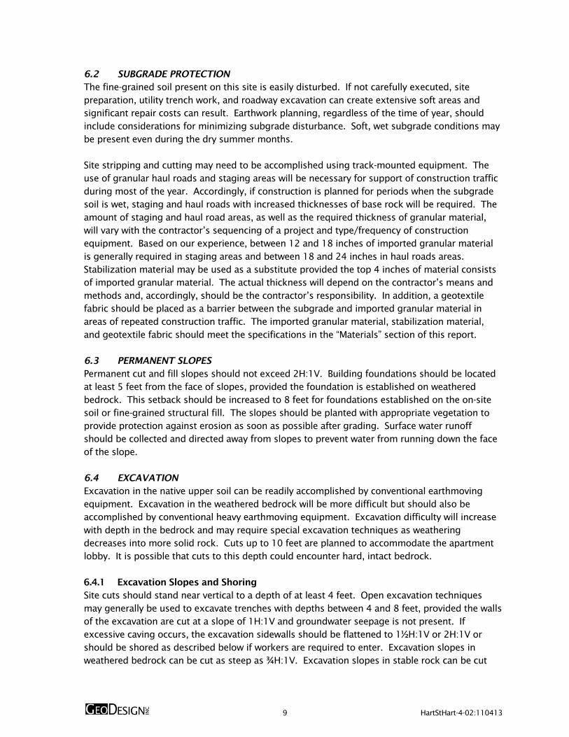
6.2 SUBGRADE PROTECTION The fine-grained soil present on this site is easily disturbed. If not carefully executed, site preparation, utility trench work, and roadway excavation can create extensive soft areas and significant repair costs can result. Earthwork planning, regardless of the time of year, should include considerations for minimizing subgrade disturbance. Soft, wet subgrade conditions may be present even during the dry summer months. Site stripping and cutting may need to be accomplished using track-mounted equipment. The use of granular haul roads and staging areas will be necessary for support of construction traffic during most of the year. Accordingly, if construction is planned for periods when the subgrade soil is wet, staging and haul roads with increased thicknesses of base rock will be required. The amount of staging and haul road areas, as well as the required thickness of granular material, will vary with the contractor’s sequencing of a project and type/frequency of construction equipment. Based on our experience, between 12 and 18 inches of imported granular material is generally required in staging areas and between 18 and 24 inches in haul roads areas. Stabilization material may be used as a substitute provided the top 4 inches of material consists of imported granular material. The actual thickness will depend on the contractor’s means and methods and, accordingly, should be the contractor’s responsibility. In addition, a geotextile fabric should be placed as a barrier between the subgrade and imported granular material in areas of repeated construction traffic. The imported granular material, stabilization material, and geotextile fabric should meet the specifications in the “Materials” section of this report. 6.3 PERMANENT SLOPES Permanent cut and fill slopes should not exceed 2H:1V. Building foundations should be located at least 5 feet from the face of slopes, provided the foundation is established on weathered bedrock. This setback should be increased to 8 feet for foundations established on the on-site soil or fine-grained structural fill. The slopes should be planted with appropriate vegetation to provide protection against erosion as soon as possible after grading. Surface water runoff should be collected and directed away from slopes to prevent water from running down the face of the slope. 6.4 EXCAVATION Excavation in the native upper soil can be readily accomplished by conventional earthmoving equipment. Excavation in the weathered bedrock will be more difficult but should also be accomplished by conventional heavy earthmoving equipment. Excavation difficulty will increase with depth in the bedrock and may require special excavation techniques as weathering decreases into more solid rock. Cuts up to 10 feet are planned to accommodate the apartment lobby. It is possible that cuts to this depth could encounter hard, intact bedrock. 6.4.1 Excavation Slopes and Shoring Site cuts should stand near vertical to a depth of at least 4 feet. Open excavation techniques may generally be used to excavate trenches with depths between 4 and 8 feet, provided the walls of the excavation are cut at a slope of 1H:1V and groundwater seepage is not present. If excessive caving occurs, the excavation sidewalls should be flattened to 1½H:1V or 2H:1V or should be shored as described below if workers are required to enter. Excavation slopes in weathered bedrock can be cut as steep as ¾H:1V. Excavation slopes in stable rock can be cut

10 HartStHart-4-02:110413
vertical. It is the contractor’s responsibility to select the excavation methods, monitor the excavations for safety, and provide shoring required to protect personnel and adjacent improvements. If box shoring is used, it should be understood that box shoring is a safety feature used to protect workers and does not prevent caving. The presence of caved material will limit the ability to properly backfill and compact the trenches. The contractor should be prepared to fill voids between the box shoring and the sidewalls of the trenches with sand or gravel before caving occurs. If shoring is used, we recommend that the type and design of the shoring system be the responsibility of the contractor, who is in the best position to choose a system that fits the overall plan of operation. All excavations should be made in accordance with applicable OSHA and state regulations. 6.4.2 Dewatering Perched groundwater may be encountered in shallow excavations during periods of wet weather. It should be possible to remove groundwater by pumping from sumps. 6.4.3 Safety All excavations should be made in accordance with applicable OSHA requirements and regulations of the state, county, and local jurisdiction. While this report describes certain approaches to excavation and dewatering, the contract documents should specify that the contractor is responsible for selecting excavation and dewatering methods, monitoring the excavations for safety, and providing shoring (as required) to protect personnel and adjacent structural elements. 6.5 MATERIALS 6.5.1 Structural Fill 6.5.1.1 General Fill should be placed on subgrade that has been prepared in conformance with the “Site Preparation” section of this report. A variety of material may be used as structural fill at the site. However, all material used as structural fill should be free of organic matter or other unsuitable material and should meet the specifications provided in OSSC 00330 (Earthwork), OSSC 00400 (Drainage and Sewers), and OSSC 02600 (Aggregates), depending on the application. A brief characterization of some of the acceptable materials and our recommendations for their use as structural fill is provided below. 6.5.1.2 On-Site Soil The material at the site should be suitable for use as general structural fill provided it is properly moisture conditioned; free of debris, organic material, and particles over 6 inches in diameter; and meets the specifications provided in OSSC 00330.12 (Borrow Material). Therefore, moisture conditioning (drying) will likely be required to use on-site silty soil and weathered bedrock for structural fill at all times of the year except the dry summer months. Accordingly, extended dry weather will be required to adequately condition and place this
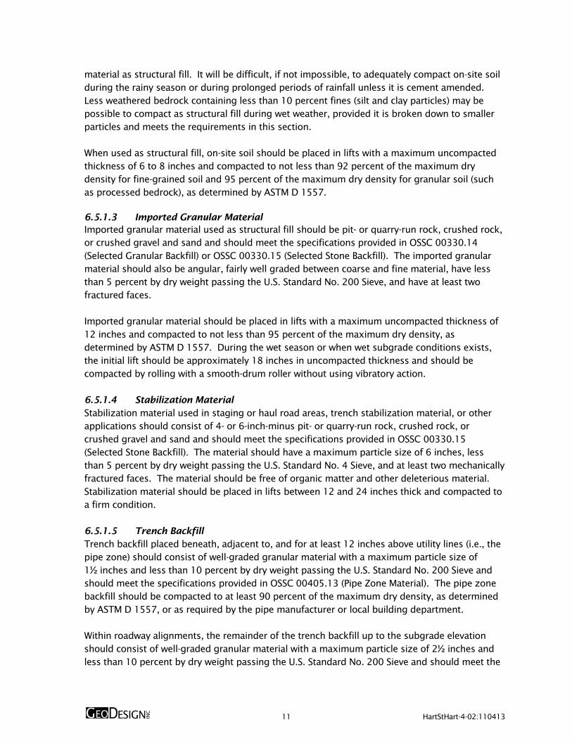
11 HartStHart-4-02:110413
material as structural fill. It will be difficult, if not impossible, to adequately compact on-site soil during the rainy season or during prolonged periods of rainfall unless it is cement amended. Less weathered bedrock containing less than 10 percent fines (silt and clay particles) may be possible to compact as structural fill during wet weather, provided it is broken down to smaller particles and meets the requirements in this section. When used as structural fill, on-site soil should be placed in lifts with a maximum uncompacted thickness of 6 to 8 inches and compacted to not less than 92 percent of the maximum dry density for fine-grained soil and 95 percent of the maximum dry density for granular soil (such as processed bedrock), as determined by ASTM D 1557. 6.5.1.3 Imported Granular Material Imported granular material used as structural fill should be pit- or quarry-run rock, crushed rock, or crushed gravel and sand and should meet the specifications provided in OSSC 00330.14 (Selected Granular Backfill) or OSSC 00330.15 (Selected Stone Backfill). The imported granular material should also be angular, fairly well graded between coarse and fine material, have less than 5 percent by dry weight passing the U.S. Standard No. 200 Sieve, and have at least two fractured faces. Imported granular material should be placed in lifts with a maximum uncompacted thickness of 12 inches and compacted to not less than 95 percent of the maximum dry density, as determined by ASTM D 1557. During the wet season or when wet subgrade conditions exists, the initial lift should be approximately 18 inches in uncompacted thickness and should be compacted by rolling with a smooth-drum roller without using vibratory action. 6.5.1.4 Stabilization Material Stabilization material used in staging or haul road areas, trench stabilization material, or other applications should consist of 4- or 6-inch-minus pit- or quarry-run rock, crushed rock, or crushed gravel and sand and should meet the specifications provided in OSSC 00330.15 (Selected Stone Backfill). The material should have a maximum particle size of 6 inches, less than 5 percent by dry weight passing the U.S. Standard No. 4 Sieve, and at least two mechanically fractured faces. The material should be free of organic matter and other deleterious material. Stabilization material should be placed in lifts between 12 and 24 inches thick and compacted to a firm condition. 6.5.1.5 Trench Backfill Trench backfill placed beneath, adjacent to, and for at least 12 inches above utility lines (i.e., the pipe zone) should consist of well-graded granular material with a maximum particle size of 1½ inches and less than 10 percent by dry weight passing the U.S. Standard No. 200 Sieve and should meet the specifications provided in OSSC 00405.13 (Pipe Zone Material). The pipe zone backfill should be compacted to at least 90 percent of the maximum dry density, as determined by ASTM D 1557, or as required by the pipe manufacturer or local building department. Within roadway alignments, the remainder of the trench backfill up to the subgrade elevation should consist of well-graded granular material with a maximum particle size of 2½ inches and less than 10 percent by dry weight passing the U.S. Standard No. 200 Sieve and should meet the

12 HartStHart-4-02:110413
specifications provided in OSSC 00405.14 (Trench Backfill; Class B, C, or D). This material should be compacted to at least 90 percent of the maximum dry density, as determined by ASTM D 1557, or as required by the pipe manufacturer or local building department. The upper 3 feet of the trench backfill should be compacted to at least 95 percent of the maximum dry density, as determined by ASTM D 1557. Outside of structural improvement areas (e.g., roadway alignments or building pads) trench backfill placed above the pipe zone may consist of general fill material that is free of organics and material over 6 inches in diameter and meets the specifications provided in OSSC 00405.14 (Trench Backfill; Class A, B, C, or D). This general trench backfill should be compacted to at least 90 percent of the maximum dry density, as determined by ASTM D 1557, or as required by the pipe manufacturer or local building department. 6.5.1.6 Drain Rock Drain rock should consist of angular, granular material with a maximum particle size of 2 inches and should meet the specifications provided in OSSC 00430.11 (Granular Drain Backfill Material). The material should be free of roots, organic matter, and other unsuitable material; have less than 2 percent by dry weight passing the U.S. Standard No. 200 Sieve (washed analysis); and have at least two mechanically fractured faces. Drain rock should be compacted to a well-keyed, firm condition. 6.5.1.7 Aggregate Base Rock Imported granular material used as base rock for building floor slabs should consist of ¾- or 1½-inch-minus material (depending on the application) and meet the requirements in OSSC 00641 (Aggregate Subbase, Base, and Shoulders). In addition, the aggregate should have less than 5 percent by dry weight passing the U.S. Standard No. 200 Sieve. The aggregate base should be compacted to not less than 95 percent of the maximum dry density, as determined by ASTM D 1557. 6.5.1.8 Retaining Wall Select Backfill Backfill material placed behind retaining walls and extending a horizontal distance of ½H, where H is the height of the retaining wall, should consist of select granular material that meets the specifications provided in OSSC 00510.12 (Granular Wall Backfill). We recommend the select granular wall backfill be separated from general fill, native soil, and/or topsoil using a geotextile fabric that meets the specifications provided below for drainage geotextiles. The wall backfill should be compacted to a minimum of 95 percent of the maximum dry density, as determined by ASTM D 1557. However, backfill located within a horizontal distance of 3 feet from a retaining wall should only be compacted to approximately 90 percent of the maximum dry density, as determined by ASTM D 1557. Backfill placed within 3 feet of the wall should be compacted in lifts less than 6 inches thick using hand-operated tamping equipment (such as a jumping jack or vibratory plate compactor). If flatwork (sidewalks or pavements) will be placed atop the wall backfill, we recommend that the upper 2 feet of material be compacted to 95 percent of the maximum dry density, as determined by ASTM D 1557.

13 HartStHart-4-02:110413
6.5.2 Geotextile Fabric 6.5.2.1 Subgrade Geotextile Subgrade geotextile should conform to OSSC Table 02320-1 and OSSC 00350 (Geosynthetic Installation). The geotextile should have a Level “B” certification. A minimum initial aggregate base lift of 6 inches is required over geotextiles. 6.5.2.2 Drainage Geotextile Drainage geotextile should conform to Type 2 material of OSSC Table 02320-1 and OSSC 00350 (Geosynthetic Installation). The geotextile should have a Level “B” certification. A minimum initial aggregate base lift of 6 inches is required over geotextiles. 6.6 EROSION CONTROL The site soil is susceptible to erosion; therefore, erosion control measures should be carefully planned and in place before construction begins. Surface water runoff should be collected and directed away from slopes to prevent water from running down the slope face. Erosion control measures (such as straw bales, sediment fences, and temporary detention and settling basins) should be used in accordance with local and state ordinances. 7.0 OBSERVATION OF CONSTRUCTION Satisfactory foundation and earthwork performance depends to a large degree on quality of construction. Sufficient observation of the contractor's activities is a key part of determining that the work is completed in accordance with the construction drawings and specifications. Subsurface conditions observed during construction should be compared with those encountered during the subsurface exploration. Recognition of changed conditions often requires experience; therefore, qualified personnel should visit the site with sufficient frequency to detect if subsurface conditions change significantly from those anticipated. We recommend that GeoDesign be retained to observe earthwork activities, including stripping, proofrolling of the subgrade and repair of soft areas, footing subgrade preparation, performing laboratory compaction and field moisture-density tests, observing final proofrolling of the pavement subgrade and base rock, and asphalt placement and compaction. 8.0 LIMITATIONS We have prepared this report for use by Colab Architecture + Urban Design, LLC and other members of the design and construction teams for the proposed project. The data and report can be used for bidding or estimating purposes, but our report, conclusions, and interpretations should not be construed as warranty of the subsurface conditions and are not applicable to other nearby building sites. Exploration observations indicate soil conditions only at specific locations and only to the depths penetrated. They do not necessarily reflect soil strata or water level variations that may exist between exploration locations. If subsurface conditions differing from those described are noted during the course of excavation and construction, re-evaluation will be necessary.

14 HartStHart-4-02:110413
The site development plans and design details were preliminary at the time this report was prepared. When the design has been finalized and if there are changes in the site grades or location, configuration, design loads, or type of construction for the buildings, and walls, the conclusions and recommendations presented may not be applicable. If design changes are made, we request that we be retained to review our conclusions and recommendations and to provide a written modification or verification. The scope does not include services related to construction safety precautions, and our recommendations are not intended to direct the contractor's methods, techniques, sequences, or procedures, except as specifically described in our report for consideration in design. Within the limitations of scope, schedule, and budget, our services have been executed in accordance with generally accepted practices in this area at the time the report was prepared. No warranty, express or implied, should be understood.
We appreciate the opportunity to be of service to you. Please call if you have questions concerning this report or if we can provide additional services. Sincerely, GeoDesign, Inc. Scott P. McDevitt, P.E., G.E. Project Engineer Julio C. Vela, Ph.D., P.E., G.E. Principal Engineer

FIGURES

SITE
Prin
ted B
y: m
mille
r | Pr
int
Dat
e: 1
1/4
/2013 1
2:3
6:4
6 P
M
File
Nam
e: J:\
E-L\
Har
tStH
art\
Har
tStH
art-
4\H
artS
tHar
t-4-0
2\F
igure
s\C
AD
\Har
tStH
art-
4-0
2-V
M01.d
wg | L
ayout:
FIG
URE
1
Off 503.968.8787 Fax 503.968.3068
Portland OR 97224
15575 SW Sequoia Parkway - Suite 100
VICINITY MAP
FIGURE 1
HARTSTHART-4-02
NOVEMBER 2013VIEW POINT TERRACE APARTMENT BUILDING
PORTLAND, OR
0
(SCALE IN APPROXIMATE FEET)
N
2000 4000VICINITY MAP BASED ON AERIALPHOTOGRAPH OBTAINED FROMGOOGLE EARTH PRO®

TP-1
TP-2
TP-3
TP-4
SW THOMAS STREET
SW
VIE
W P
OIN
T T
ER
RA
CE
Off 503.968.8787 Fax 503.968.3068
Portland OR 97224
15575 SW Sequoia Parkway - Suite 100
Prin
ted B
y: m
mille
r | Pr
int
Dat
e: 1
1/4
/2013 1
2:3
7:5
7 P
M
File
Nam
e: J:\
E-L\
Har
tStH
art\
Har
tStH
art-
4\H
artS
tHar
t-4-0
2\F
igure
s\C
AD
\Har
tStH
art-
4-0
2-S
P01.d
wg | L
ayout:
FIG
URE
2
SITE PLAN
FIGURE 2
HARTSTHART-4-02
NOVEMBER 2013VIEW POINT TERRACE APARTMENT BUILDING
PORTLAND, OR
SITE PLAN BASED ON DRAWING PROVIDED BYHARTMAN STRONG HARTMAN,OCTOBER 23, 2013
TP-1
LEGEND:
TEST PIT
0
(SCALE IN FEET)
N
20 40

APPENDIX

A-1 HartStHart-4-02:110413
APPENDIX FIELD EXPLORATIONS GENERAL We explored subsurface conditions at site by excavating four test pits (TP-1 through TP-4) to depths ranging between 4.0 and 5.0 feet BGS. Excavation services were provided by the project owner. Figure 2 shows the approximate exploration locations relative to proposed site features. Locations were determined by pacing from existing site features and should be considered accurate to the degree implied by the methods used. A member of our geotechnical staff observed all explorations and obtained representative samples of the various soils encountered in the explorations for geotechnical laboratory testing. Classifications and sampling intervals are presented on the exploration logs included in this appendix. SOIL SAMPLING Representative grab samples of the soil were obtained from the walls and/or base of the test pits using the excavator bucket. The exploration logs show the sampler type next to the sample location. SOIL CLASSIFICATION The soil samples were classified in accordance with the “Exploration Key” (Table A-1) and “Soil Classification System” (Table A-2), which are included in this appendix. The exploration logs indicate the depths at which the soil or its characteristics change, although the change actually could be gradual. If the change occurred between sample locations, the depth was interpreted. Classifications and sampling intervals are presented on the exploration logs included in this appendix. LABORATORY TESTING CLASSIFICATION The soil samples were classified in the laboratory to confirm field classifications. The laboratory classifications are presented on the exploration logs if those classifications differed from the field classifications. MOISTURE CONTENT DETERMINATION We determined the natural moisture content of selected soil samples in general accordance with ASTM D 2216. The natural moisture content is a ratio of the weight of the water to soil in a test sample and is expressed as a percentage. The test results are included on the exploration logs presented in this appendix.

SYMBOL SAMPLING DESCRIPTION
Location of sample obtained in general accordance with ASTM D 1586 Standard Penetration Test
with recovery
Location of sample obtained using thin-wall Shelby tube or Geoprobe® sampler in general
accordance with ASTM D 1587 with recovery
Location of sample obtained using Dames & Moore sampler and 300-pound hammer or pushed
with recovery
Location of sample obtained using Dames & Moore and 140-pound hammer or pushed with
recovery
Location of sample obtained using 3-inch-O.D. California split-spoon sampler and 140-pound
hammer
Location of grab sample
Rock coring interval
Water level during drilling
Water level taken on date shown
GEOTECHNICAL TESTING EXPLANATIONS
ATT
CBR
CON
DD
DS
HYD
MC
MD
OC
P
Atterberg Limits
California Bearing Ratio
Consolidation
Dry Density
Direct Shear
Hydrometer Gradation
Moisture Content
Moisture-Density Relationship
Organic Content
Pushed Sample
PP
P200
RES
SIEV
TOR
UC
VS
kPa
Pocket Penetrometer
Percent Passing U.S. Standard No. 200
Sieve
Resilient Modulus
Sieve Gradation
Torvane
Unconfined Compressive Strength
Vane Shear
Kilopascal
ENVIRONMENTAL TESTING EXPLANATIONS
CA
P
PID
ppm
Sample Submitted for Chemical Analysis
Pushed Sample
Photoionization Detector Headspace
Analysis
Parts per Million
ND
NS
SS
MS
HS
Not Detected
No Visible Sheen
Slight Sheen
Moderate Sheen
Heavy Sheen
15575 SW Sequoia Parkway - Suite 100
Portland OR 97224
Off 503.968.8787 Fax 503.968.3068
EXPLORATION KEY TABLE A-1
Graphic Log of Soil and Rock Types
Inferred contact between soil or
rock units (at approximate
depths indicated)
Observed contact between soil or
rock units (at depth indicated)

RELATIVE DENSITY - COARSE-GRAINED SOILS
Relative Density Standard Penetration
Resistance
Dames & Moore Sampler
(140-pound hammer)
Dames & Moore Sampler
(300-pound hammer)
Very Loose 0 – 4 0 - 11 0 - 4
Loose 4 – 10 11 - 26 4 - 10
Medium Dense 10 – 30 26 - 74 10 - 30
Dense 30 – 50 74 - 120 30 - 47
Very Dense More than 50 More than 120 More than 47
CONSISTENCY - FINE-GRAINED SOILS
Consistency Standard Penetration
Resistance
Dames & Moore Sampler
(140-pound hammer)
Dames & Moore Sampler
(300-pound hammer)
Unconfined Compressive
Strength (tsf)
Very Soft Less than 2 Less than 3 Less than 2 Less than 0.25
Soft 2 - 4 3 – 6 2 - 5 0.25 - 0.50
Medium Stiff 4 - 8 6 – 12 5 - 9 0.50 - 1.0
Stiff 8 - 15 12 – 25 9 - 19 1.0 - 2.0
Very Stiff 15 - 30 25 – 65 19 – 31 2.0 - 4.0
Hard More than 30 More than 65 More than 31 More than 4.0
PRIMARY SOIL DIVISIONS GROUP SYMBOL GROUP NAME
COARSE-GRAINED
SOILS
(more than 50%
retained on
No. 200 sieve)
GRAVEL
(more than 50% of
coarse fraction
retained on
No. 4 sieve)
CLEAN GRAVELS
(< 5% fines) GW or GP GRAVEL
GRAVEL WITH FINES
(≥ 5% and ≤ 12% fines)
GW-GM or GP-GM GRAVEL with silt
GW-GC or GP-GC GRAVEL with clay
GRAVELS WITH FINES
(> 12% fines)
GM silty GRAVEL
GC clayey GRAVEL
GC-GM silty, clayey GRAVEL
SAND
(50% or more of
coarse fraction
passing
No. 4 sieve)
CLEAN SANDS
(<5% fines) SW or SP SAND
SANDS WITH FINES
(≥ 5% and ≤ 12% fines)
SW-SM or SP-SM SAND with silt
SW-SC or SP-SC SAND with clay
SANDS WITH FINES
(> 12% fines)
SM silty SAND
SC clayey SAND
SC-SM silty, clayey SAND
FINE-GRAINED
SOILS
(50% or more
passing
No. 200 sieve)
SILT AND CLAY
Liquid limit less than 50
ML SILT
CL CLAY
CL-ML silty CLAY
OL ORGANIC SILT or ORGANIC CLAY
Liquid limit 50 or
greater
MH SILT
CH CLAY
OH ORGANIC SILT or ORGANIC CLAY
HIGHLY ORGANIC SOILS PT PEAT
MOISTURE
CLASSIFICATION ADDITIONAL CONSTITUENTS
Term Field Test
Secondary granular components or other materials
such as organics, man-made debris, etc.
Percent
Silt and Clay In:
Percent
Sand and Gravel In:
dry very low moisture,
dry to touch
Fine-Grained
Soils
Coarse-
Grained Soils
Fine-Grained
Soils
Coarse-
Grained Soils
moist damp, without
visible moisture
< 5 trace trace < 5 trace trace
5 – 12 minor with 5 – 15 minor minor
wet visible free water,
usually saturated
> 12 some silty/clayey 15 – 30 with with
> 30 sandy/gravelly Indicate %
15575 SW Sequoia Parkway - Suite 100
Portland OR 97224
Off 503.968.8787 Fax 503.968.3068
SOIL CLASSIFICATION SYSTEM TABLE A-2

None to minor caving observed at0.0 feet.
No groundwater seepage observedto the depth explored.
Surface elevation was notmeasured at the time ofexploration.
4.3
Medium dense, brown-gray COBBLESwith gravel (GP), minor clay and sand,trace organics (roots); moist, organicsare 1/4-inch diameter (highly weatheredbedrock, 2 1/2-inch-thick root zone).
grades to without organics at 3.0 feet
grades to dense at 3.8 feet
Exploration terminated due to refusal ata depth of 4.3 feet.
COMMENTSMOISTURECONTENT
(%)
TEST PIT
TES
T P
IT L
OG
- 2
PER
PA
GE
HA
RT
STH
AR
T-4
-02
-TP1
_4.G
PJ
GEO
DES
IGN
.GD
T
PRIN
T D
AT
E: 1
1/4
/13
:KT
COMPLETED: 05/06/13
ELEV
AT
ION
DEP
TH
SAM
PLE
FIGURE A-1PORTLAND, OR
HARTSTHART-4-02
VIEW POINT TERRACE APARTMENT BUILDING
GR
APH
IC L
OG
MATERIAL DESCRIPTION
TES
TIN
G
DEPTHFEET
LOGGED BY: JGH
NOVEMBER 201315575 SW Sequoia Parkway - Suite 100
Portland OR 97224Off 503.968.8787 Fax 503.968.3068
EXCAVATION METHOD: mini trackhoe (see report text)
EXCAVATED BY: Client-supplied excavator
None to minor caving observed at0.0 feet.
No groundwater seepage observedto the depth explored.
Surface elevation was notmeasured at the time ofexploration.
2.8
4.0
Medium stiff, brown-dark brown SILT(ML), minor sand, gravel, and clay, traceorganics (roots); moist, sand is fine,organics are up to 1-inch diameter(colluvium, 6-inch-thick root zone).
Medium dense to dense, brown-grayCOBBLES with gravel and clay (GP-GC),minor sand, trace organics (roots);moist, organics are mm scale up to 1/2-inch diameter (highly weatheredbedrock).Exploration terminated due to refusal ata depth of 4.0 feet.
0 50 100
0 50 100
TP-10.0
2.5
5.0
7.5
0 50 100
0 50 100
TP-20.0
2.5
5.0
7.5

Minor caving observed from 0.0 to4.0 feet.
No groundwater seepage observedto the depth explored.
Surface elevation was notmeasured at the time ofexploration.
0.5
4.0
Medium dense, dark brown, siltyGRAVEL with organics (GM); moist,organics are 1/2-inch diameter (topsoil,6-inch-thick root zone).Medium dense, brown-gray COBBLESwith gravel, silt, clay, and sand (GP-GC);moist (highway weathered bedrock).
grades to dense at 3.5 feet
Exploration terminated due to refusal ata depth of 4.0 feet.
COMMENTSMOISTURECONTENT
(%)
TEST PIT
TES
T P
IT L
OG
- 2
PER
PA
GE
HA
RT
STH
AR
T-4
-02
-TP1
_4.G
PJ
GEO
DES
IGN
.GD
T
PRIN
T D
AT
E: 1
1/4
/13
:KT
COMPLETED: 05/06/13
ELEV
AT
ION
DEP
TH
SAM
PLE
FIGURE A-2PORTLAND, OR
HARTSTHART-4-02
VIEW POINT TERRACE APARTMENT BUILDING
GR
APH
IC L
OG
MATERIAL DESCRIPTION
TES
TIN
G
DEPTHFEET
LOGGED BY: JGH
NOVEMBER 201315575 SW Sequoia Parkway - Suite 100
Portland OR 97224Off 503.968.8787 Fax 503.968.3068
EXCAVATION METHOD: mini trackhoe (see report text)
EXCAVATED BY: Client-supplied excavator
Minor caving observed from 0.0 to4.0 feet.
No groundwater seepage observedto the depth explored.
Surface elevation was notmeasured at the time ofexploration.
0.9
5.0
Soft to medium stiff, dark brown SILTwith gravel and cobbles (ML), some clay,minor sand, trace organics (roots);moist, organics are up to 1-inchdiameter (topsoil, 2- to 3-inch-thick rootzone).Medium dense, brown-gray COBBLESwith clay and gravel (GP-GC), minorsand, trace organics (roots); moist,organics are 1/4-inch diameter (highlyweathered basalt).grades to without organics at 4.0 feet
Exploration terminated due to refusal ata depth of 5.0 feet.
0 50 100
0 50 100
TP-30.0
2.5
5.0
7.5
0 50 100
0 50 100
TP-40.0
2.5
5.0
7.5

TP-1 2.5 36
TP-2 2.0 28
TP-3 2.0 37
TP-4 3.0 39
GRAVEL(PERCENT)
LIQUIDLIMIT
(PERCENT)
SAMPLEDEPTH(FEET)
SUMMARY OF LABORATORY DATA
ELEVATION(FEET)
P200(PERCENT)
PLASTICLIMIT
(PERCENT)
PLASTICITYINDEX
(PERCENT)
SIEVE ATTERBERG LIMITSMOISTURECONTENT(PERCENT)
SAMPLE INFORMATION
EXPLORATIONNUMBER
SAND(PERCENT)
DRYDENSITY
(PCF)
HARTSTHART-4-02
NOVEMBER 2013 VIEW POINT TERRACE APARTMENT BUILDINGPORTLAND, OR FIGURE A-3
15575 SW Sequoia Parkway - Suite 100Portland OR 97224
Off 503.968.8787 Fax 503.968.3068
LAB S
UM
MA
RY
HA
RT
STH
AR
T-4
-02
-TP1
_4.G
PJ
GEO
DES
IGN
.GD
T
PRIN
T D
AT
E: 1
1/4
/13
:KT

ACRONYMS

HartStHart-4-02:110413
ACRONYMS ASCE American Society of Civil Engineers ASTM American Society for Testing and Materials BGS below ground surface g gravitational acceleration (32.2 feet/second2) H:V horizontal to vertical IBC International Building Code MCE maximum considered earthquake OSHA Occupational Safety and Health Administration OSSC Oregon Standard Specifications for Construction (2008) pcf pounds per cubic foot PGA peak ground acceleration psf pounds per square foot psi pounds per square inch SOSSC State of Oregon Structural Specialty Code