
REPORT DOCUMENTATION PAGE Form Approved · REPORT DOCUMENTATION PAGE Form Approved ... The DTP...
71
Standard Form 298 (Rev. 8-98) Prescribed by ANSI Std. Z39-18 REPORT DOCUMENTATION PAGE Form Approved OMB No. 0704-0188 The public reporting burden for this collection of information is estimated to average 1 hour per response, including the time for reviewing instructions, searching existing data sources, gathering and maintaining the data needed, and completing and reviewing the collection of information. Send comments regarding this burden estimate or any other aspect of this collection of information, including suggestions for reducing this burden, to Department of Defense, Washington Headquarters Services, Directorate for information on Operations and Reports (0704- 0188), 1215 Jefferson Davis Highway, Suite 1204, Arlington, VA 22202-4302. Respondents should be aware that notwithstanding any other provision of law, no person shall be subject to any penalty for failing to comply with a collection of information if it does not display a currently valid OMB control number. PLEASE DO NOT RETURN YOUR FORM TO THE ABOVE ADDRESS. 1. REPORT DATE (DD-MM-YYYY) 28-09-2011 2. REPORT TYPE Final 3. DATES COVERED (From - To) 4. TITLE AND SUBTITLE Test Operations Procedure (TOP) 08-2-198 Collective Protection (ColPro) Field Testing 5a. CONTRACT NUMBER 5b. GRANT NUMBER 5c. PROGRAM ELEMENT NUMBER 6. AUTHORS 5d. PROJECT NUMBER 5e. TASK NUMBER 5f. WORK UNIT NUMBER 7. PERFORMING ORGANIZATION NAME(S) AND ADDRESS(ES) U.S. Army Dugway Proving Ground West Desert Test Center (TEDT-DPW-CTC) Dugway, UT 84022-5000 8. PERFORMING ORGANIZATION REPORT NUMBER TOP 08-2-198 9. SPONSORING/MONITORING AGENCY NAME(S) AND ADDRESS(ES) Range Infrastructure Division (CSTE-TM) US Army Test and Evaluation Command 2202 Aberdeen Boulevard Aberdeen Proving Ground, MD 21005 10. SPONSOR/MONITOR’S ACRONYM(S) 11. SPONSOR/MONITOR’S REPORT NUMBER(S) Same as item 8 12. DISTRIBUTION/AVAILABILITY STATEMENT Distribution Statement A. Approved for public release; distribution unlimited. 13. SUPPLEMENTARY NOTES Defense Technical Information Center (DTIC), AD No.: 14. ABSTRACT This Test Operations Procedure (TOP) provides the standard process for preparation, planning, conduct, and reporting for field testing of collective protection (ColPro) systems. This process is designed to evaluate the effectiveness of mo- bile and stationary ColPro systems under operational field conditions during exposure to an agent using a simulant va- por cloud. The evaluation is based on a comparison of the simulant challenge concentration and any simulant breakthrough concentration within the toxic-free areas (TFAs) of the ColPro system. 15. SUBJECT TERMS MINICAMS®; Gasmet™; solid sorbent tube; SST; challenge concentration; breakthrough concentration; real-time moni- tor, RTM; Near real-time monitor; NRTM; simulant exposure area; SEA; total exposure dosage; TED; protection factor; PF; concentration time; Ct 16. SECURITY CLASSIFICATION OF: 17. LIMITATION OF ABSTRACT SAR 18. NUMBER OF PAGES 70 19a. NAME OF RESPONSIBLE PERSON a. REPORT B. ABSTRACT C. THIS PAGE Unclassified Unclassified Unclassified 19b. TELEPHONE NUMBER (include area code)
Transcript of REPORT DOCUMENTATION PAGE Form Approved · REPORT DOCUMENTATION PAGE Form Approved ... The DTP...
Standard Form 298 (Rev. 8-98)
Prescribed by ANSI Std. Z39-18
REPORT DOCUMENTATION PAGE Form Approved
OMB No. 0704-0188
The public reporting burden for this collection of information is estimated to average 1 hour per response, including the time for reviewing instructions, searching existing data sources, gathering and maintaining the data needed, and completing and reviewing the collection of information. Send comments regarding this burden estimate or any other aspect of this collection of information, including suggestions for reducing this burden, to Department of Defense, Washington Headquarters Services, Directorate for information on Operations and Reports (0704-0188), 1215 Jefferson Davis Highway, Suite 1204, Arlington, VA 22202-4302. Respondents should be aware that notwithstanding any other provision of law, no person shall be subject to any penalty for failing to comply with a collection of information if it does not display a currently valid OMB control number. PLEASE DO NOT RETURN YOUR FORM TO THE ABOVE ADDRESS.
1. REPORT DATE (DD-MM-YYYY) 28-09-2011
2. REPORT TYPE
Final 3. DATES COVERED (From - To)
4. TITLE AND SUBTITLE Test Operations Procedure (TOP) 08-2-198 Collective Protection (ColPro) Field Testing
5a. CONTRACT NUMBER 5b. GRANT NUMBER 5c. PROGRAM ELEMENT NUMBER
6. AUTHORS
5d. PROJECT NUMBER 5e. TASK NUMBER 5f. WORK UNIT NUMBER
7. PERFORMING ORGANIZATION NAME(S) AND ADDRESS(ES) U.S. Army Dugway Proving Ground West Desert Test Center (TEDT-DPW-CTC) Dugway, UT 84022-5000
8. PERFORMING ORGANIZATION REPORT NUMBER TOP 08-2-198
9. SPONSORING/MONITORING AGENCY NAME(S) AND ADDRESS(ES) Range Infrastructure Division (CSTE-TM) US Army Test and Evaluation Command 2202 Aberdeen Boulevard Aberdeen Proving Ground, MD 21005
10. SPONSOR/MONITOR’S ACRONYM(S)
11. SPONSOR/MONITOR’S REPORT NUMBER(S) Same as item 8
12. DISTRIBUTION/AVAILABILITY STATEMENT Distribution Statement A. Approved for public release; distribution unlimited. 13. SUPPLEMENTARY NOTES Defense Technical Information Center (DTIC), AD No.: 14. ABSTRACT This Test Operations Procedure (TOP) provides the standard process for preparation, planning, conduct, and reporting for field testing of collective protection (ColPro) systems. This process is designed to evaluate the effectiveness of mo-bile and stationary ColPro systems under operational field conditions during exposure to an agent using a simulant va-por cloud. The evaluation is based on a comparison of the simulant challenge concentration and any simulant breakthrough concentration within the toxic-free areas (TFAs) of the ColPro system. 15. SUBJECT TERMS MINICAMS®; Gasmet™; solid sorbent tube; SST; challenge concentration; breakthrough concentration; real-time moni-tor, RTM; Near real-time monitor; NRTM; simulant exposure area; SEA; total exposure dosage; TED; protection factor; PF; concentration time; Ct
16. SECURITY CLASSIFICATION OF: 17. LIMITATION OF ABSTRACT SAR
18. NUMBER OF PAGES
70
19a. NAME OF RESPONSIBLE PERSON
a. REPORT B. ABSTRACT C. THIS PAGE
Unclassified Unclassified Unclassified 19b. TELEPHONE NUMBER (include area code)

(This page is intentionally blank.)
US ARMY TEST AND EVALUATION COMMAND TEST OPERATIONS PROCEDURE
*Test Operations Procedure (TOP) 08-2-198 28 September 2011 DTIC AD No.:
COLLECTIVE PROTECTION (COLPRO) FIELD TESTING
Page Paragraph 1. SCOPE ..................................................................................................... 2 1.1 Background ............................................................................................. 2 1.2 Purpose .................................................................................................... 2 1.3 Limitations ............................................................................................... 4 2. FACILITIES AND INSTRUMENTATION ........................................... 4 2.1 Facilities .................................................................................................. 4 2.2 Equipment ............................................................................................... 5 2.3 Instrumentation ........................................................................................ 6 3. REQUIRED TEST CONDITIONS ......................................................... 8 3.1 Test Planning ........................................................................................... 8 3.2 Preparations for Test ............................................................................... 10 3.3 Safety ....................................................................................................... 11 3.4 Quality Assurance/Quality Control (QA/QC) ......................................... 12 4. TEST PROCEDURES ............................................................................ 15 4.1 Test Method Outline ................................................................................ 15 4.2 Receipt Inspection of the Instruments and the SUT ................................ 18 4.3 Pretest Procedure ..................................................................................... 20 4.4 Closed ColPro System Field Trial ........................................................... 24 4.5 ColPro Systems Entry/Exit Trials ........................................................... 28 4.6 Mobile ColPro Platform Field Trial ........................................................ 31 5. DATA REQUIRED ................................................................................. 32 5.1 Pretest Data .............................................................................................. 32 5.2 Closed ColPro System Trial Data Required ............................................ 34 5.3 ColPro Systems Entry/Exit Trial Data Required ..................................... 34 5.4 Mobile ColPro Platform Field Trial Data Required ................................ 35 5.5 Data Analysis .......................................................................................... 35 5.6 Data Tracking and Storage ...................................................................... 40 6. PRESENTATION OF DATA ................................................................. 40 APPENDIX A. ABBREVIATIONS ................................................................................. A-1 B. REFERENCES ........................................................................................ B-1 C. DUGWAY PROVING GROUND STANDARD OPERATING
PROCEDURES (SOPs) ......................................................................... C-1
Approved for public release; distribution unlimited.
TOP 08-2-198 28 September 2011
2
D. CAPABILITY AREA PROCESS ACTION TEAM (CAPAT) SIGNATURES ....................................................................................... D-1
E. DEPARTMENT OF DEFENSE (DOD) TEST AND EVALUATION STANDARD ENDORSEMENT ............................................................ E-1
1. SCOPE.
1.1 Background.
a. Collective protection (ColPro) systems are designed to provide protection of enclosed personnel and equipment from chemical warfare agent (CWA) and biological or radiological contaminants. b. Advancements in ColPro technologies provide diverse features that provide additional functions. Stationary ColPro systems allow personnel to proceed with their primary military functions without impeding the operator’s mission in a modular ColPro shelter. Mobile recon-naissance ColPro vehicles are capable of locating CWA threat areas using onboard detectors and can function as an advanced warning system. c. ColPro systems provide a toxic-free area (TFA) where personnel can function without the need of individual protection equipment (IPE) during CWA threats. The TFA is over-pressurized with filtered air to significantly reduce the potential for direct CWA intrusion. Addi-tionally, the systems have an environmental control unit and a blower equipped with a chemical, biological, and radiological (CBR) filter, which supplies clean air inside the system while main-taining positive pressure. d. Entry/exit to and from the TFA under threat conditions requires the use of an airlock or a protective entrance. The airlock functions as a staging area that permits toxic vapors from contaminated items to be purged before entering the TFA, thus allowing personnel to move from a contaminated area into the TFA with minimal contamination carryover. e. The protection efficiency of a ColPro system relies heavily on the ability of personnel to follow correct operational procedures in order to maintain a toxic-free environment within the TFA. Over pressurized systems can only reduce the risk of CWA intrusion; however, a breach can occur if a ColPro system malfunctions or if operational procedures are not strictly observed.
1.2 Purpose.
a. This Test Operations Procedure (TOP) provides the standard process for preparation, planning, conduct, and reporting for field testing of ColPro systems. The process is designed to evaluate the effectiveness of mobile and stationary ColPro systems under operational field conditions during exposure to an agent using a simulant vapor cloud.
b. For the purpose of this TOP, tents and other similar stationary ColPro shelters will be referred to as ColPro systems. Vehicles and other similar mobile ColPro shelters will be referred to as mobile ColPro platforms. When discussing both the ColPro systems and platforms, the
TOP 08-2-198 28 September 2011
3
term ColPro system under test (SUT) will be used. Also, those individuals responsible for setting up and running the test will be referred to as test personnel. Those who actually participate in the test, such as enacting the entry/exit procedures, will be referred to as test participants.
c. Field evaluation is conducted by challenging ColPro SUTs with simulant vapor clouds and comparing the simulant challenge concentration with any breakthrough simulant concentration inside the TFAs of the ColPro SUTs.
d. This TOP describes testing methods currently in use along with the parameters required for each method. However, test parameters may change depending on objectives for a particular test program. The objectives for test programs can be found in the Capability Development Document (CDD), System Performance Specification (SPS), and other program documentation.
e. This TOP is to be used as a guide in preparing test-specific test plans or detailed test plans (DTPs). The test procedures described in this document should be referenced and/or incorporated in the test-specific document.
(1) The DTP should describe the procedures required for operations that are specific to the test and the test parameters to be used. These may be based on factors such as the concept of operations requirements and/or threats to the ColPro shelter being tested.
(2) The DTP may modify the procedures to accommodate unique items or materials, or to satisfy testing requirements specified in the System Evaluation Plan (SEP) or other acquisition document. However, modifications should be made only after a full consideration of their affects on the reliability and validity of the data. If the modifications eliminate any requirements from this TOP, then the DTP must describe the modifications, their desired effect, and any changes to the assessment process. The rationale for the modifications and an analysis of the possible ramifications to the test results should also be described in the DTP.
(3) A consideration of modifications to this TOP will include a risk assessment coordinated in advance with the organizations concerned. The assessment will address the impact of the modifications to the following test areas:
(a) Safety.
(b) Test conditions.
(c) Environmental effects.
(d) Human use.
(e) Data quality.
(f) Test validity.

TOP 08-2-198 28 September 2011
4
1.3 Limitations.
a. The procedures in this TOP alone are not sufficient to assess the ability of ColPro items to protect the user. These procedures are designed to be used as part of an overall assessment program evaluating the material performance, manufacturing, and system integration with other pieces of protective equipment.
b. If a comparison with previous data is planned, special caution must be taken to use the same conditions as the desired comparison test. Results obtained by using this TOP may be compared with results from other systems tested during the same experiment or from those tested previously under the same conditions. The test conditions must be the same among compared results for statistical accuracy.
c. The results obtained by using these test procedures cannot be correlated to the full range of battlefield conditions; therefore, an absolute protection value cannot be determined.
d. This TOP provides guidance on test design issues and data requirements that should be enhanced by information from other documents, such as the SEP, the Test and Evaluation Master Plan (TEMP), and/or the DTP. For those testing programs in which a SEP is not available or applicable, the test facility should consult with the customer and use previous documents as a guide in addition to this TOP.
e. This TOP is limited to currently approved standards and procedures. Developments in practices, equipment, and analysis may necessitate new testing procedures. Additionally, standards of performance must be adjusted as technologies advance. Test procedures and parameters listed in this TOP may require updating to accommodate new technologies in test items or in test instrumentation. Any updates should be described in the test-specific DTP.
2. FACILITIES AND INSTRUMENTATION.
2.1 Facilities.
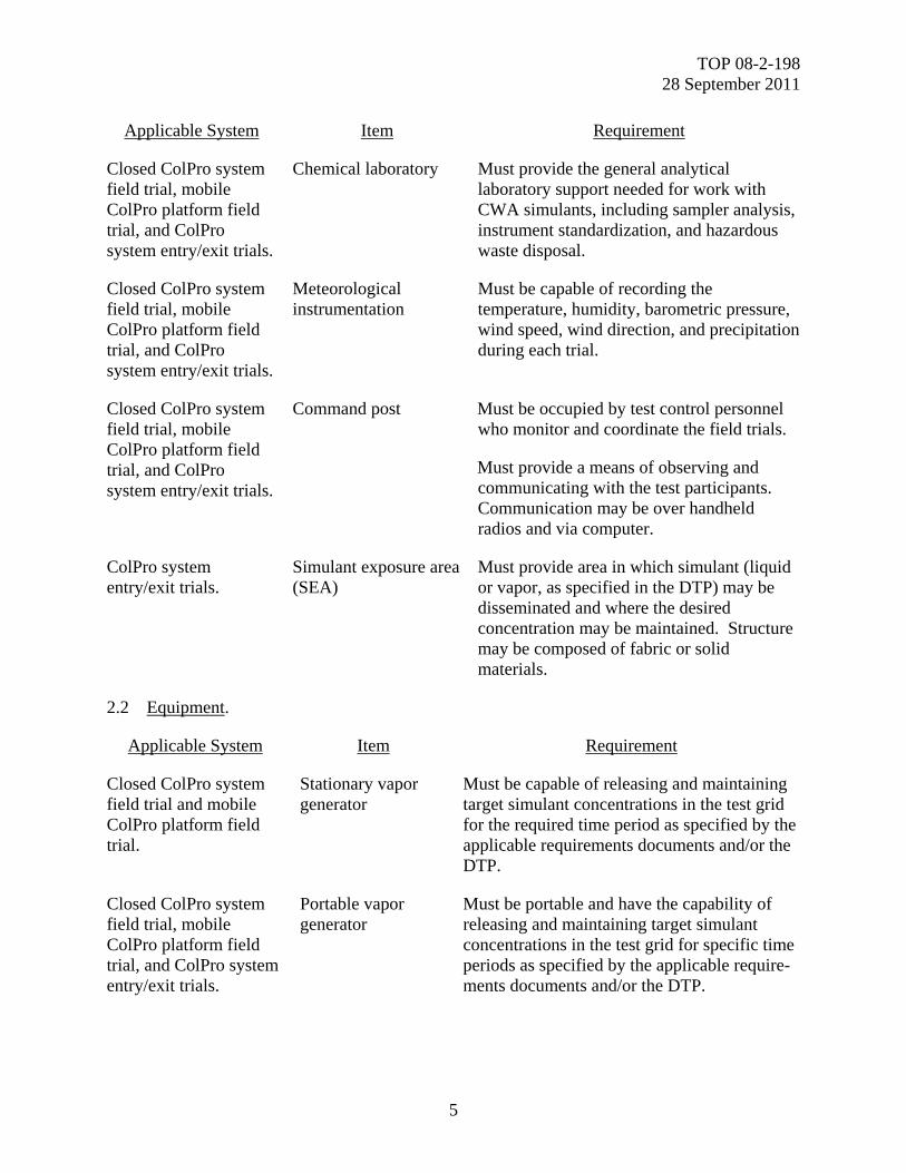
Applicable System Item Requirement
Closed ColPro system field trial, mobile ColPro platform field trial, and ColPro system entry/exit trials.
Medical treatment facility
Must be staffed with personnel trained and equipped to treat overexposure to simulant or adverse reactions to physiological stress. Staff will include emergency medical technicians (EMTs) qualified in advanced life support.
Must be equipped to measure heat stress.
Must ensure EMTs are present during all CWA simulant trials, monitor adverse physiological responses in test participants, and provide medical aid when necessary.
TOP 08-2-198 28 September 2011
5
Applicable System Item Requirement
Closed ColPro system field trial, mobile ColPro platform field trial, and ColPro system entry/exit trials.
Chemical laboratory Must provide the general analytical laboratory support needed for work with CWA simulants, including sampler analysis, instrument standardization, and hazardous waste disposal.
Closed ColPro system field trial, mobile ColPro platform field trial, and ColPro system entry/exit trials.
Meteorological instrumentation
Must be capable of recording the temperature, humidity, barometric pressure, wind speed, wind direction, and precipitation during each trial.
Closed ColPro system field trial, mobile ColPro platform field trial, and ColPro system entry/exit trials.
Command post Must be occupied by test control personnel who monitor and coordinate the field trials.
Must provide a means of observing and communicating with the test participants. Communication may be over handheld radios and via computer.
ColPro system entry/exit trials.
Simulant exposure area (SEA)
Must provide area in which simulant (liquid or vapor, as specified in the DTP) may be disseminated and where the desired concentration may be maintained. Structure may be composed of fabric or solid materials.
2.2 Equipment.
Applicable System Item Requirement
Closed ColPro system field trial and mobile ColPro platform field trial.
Stationary vapor generator
Must be capable of releasing and maintaining target simulant concentrations in the test grid for the required time period as specified by the applicable requirements documents and/or the DTP.
Closed ColPro system field trial, mobile ColPro platform field trial, and ColPro system entry/exit trials.
Portable vapor generator
Must be portable and have the capability of releasing and maintaining target simulant concentrations in the test grid for specific time periods as specified by the applicable require-ments documents and/or the DTP.

TOP 08-2-198 28 September 2011
6
2.3 Instrumentation.
Parameter Measuring Device Permissible Error of
Measurement
Challenge concentration.
Real-time monitors (RTMs), or near RTMs (NRTMs), for moni-toring atmosphere challenge concentrations of simulant vapor. MINICAMS® (a miniature, au-tomatic, continuous air-monitoring system), Gasmet™ (Gasmet Technologies Oy, Hel-sinki, Finland), sequenced solid sorbent tubes (SSTs), and ppbRAE®s (RAE Systems, San Jose, California) can be used for this function and meet the re-quirements.
±10 to 25 percent over the range of 10 to 1000 mg/m3 for each instru-ment.
The limit of detection (LOD) for the concentration monitors should be sufficiently low to meet specific test requirements for the challenge of interest (±5 percent of target concentration).
Gasmet™-like instruments may have a detection range of 1 to 5000 mg/m3 and are accurate with-in ±2 percent.
Meteorological data. Meteorological instrumentation that provides a vertical profile of environmental conditions, in-cluding wind speed, wind direc-tion, barometric pressure, humidity, temperature, and pre-cipitation.
Instrumentation must be capable of acquiring weather information and identifying horizontal wind-flow patterns across the entire vapor cloud destination path.
Portable weather information and display systems (PWIDS) have been used for this function and meet the requirements.
Temperature detection range of -40 to 60°C, accurate within ±0.5°C.
A wind speed accuracy within ±0.3 m/s.
A wind direction accuracy within ±3 degrees.
A relative humidity (RH) detection range of 0 to 90 percent, accurate within ±2 percent.
An atmospheric pressure detection range of 600 to 1060 mbar, accu-rate within ±2 mbar at temperature conditions between -20 and 40°C.
The device must be capable of sampling at least once every 5 minutes.
Cumulative dose Delayed-analysis samplers for monitoring the total challenge and total breakthrough concen-tration. Cumulative dose sam-
Extraction efficiency of ±25 per-cent should be accepted, if liquid extraction is involved.
TOP 08-2-198 28 September 2011
7
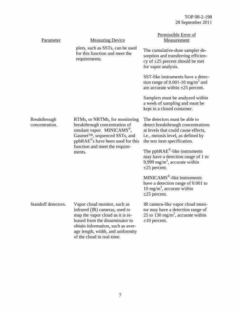
Parameter Measuring Device Permissible Error of
Measurement
plers, such as SSTs, can be used for this function and meet the requirements.
The cumulative-dose sampler de-sorption and transferring efficien-cy of ±25 percent should be met for vapor analysis.
SST-like instruments have a detec-tion range of 0.001-10 mg/m3 and are accurate within ±25 percent.
Samplers must be analyzed within a week of sampling and must be kept in a closed container.
Breakthrough concentration.
RTMs, or NRTMs, for monitoring breakthrough concentration of smulant vapor. MINICAMS®, Gasmet™, sequenced SSTs, and ppbRAE®s have been used for this function and meet the require-ments.
The detectors must be able to detect breakthrough concentrations at levels that could cause effects, i.e., meiosis level, as defined by the test item specification.
The ppbRAE®-like instruments may have a detection range of 1 to 9,999 mg/m3, accurate within ±25 percent.
MINICAMS®-like instruments have a detection range of 0.001 to 10 mg/m3, accurate within ±25 percent.
Standoff detectors. Vapor cloud monitor, such as infrared (IR) cameras, used to map the vapor cloud as it is re-leased from the disseminator to obtain information, such as aver-age length, width, and uniformity of the cloud in real-time.
IR camera-like vapor cloud moni-tor may have a detection range of 25 to 130 mg/m3, accurate within ±10 percent.
TOP 08-2-198 28 September 2011
8
3. REQUIRED TEST CONDITIONS.
3.1 Test Planning.
3.1.1 Experimental Design.
a. The test will be designed to facilitate data analysis using standard design-of-experiment techniques to minimize the number of trials needed to obtain statistical validity.
b. Test criteria must be defined before testing so that the program may be designed to obtain the required information. The resulting data must be adequate to support the intended analysis and assessments.
c. Test planning should include determination of the exact-use configuration of each test item (such as command and control, rest and relaxation, or medical configurations for tents), in conjunction with all compatible items to be used with the test item.
3.1.2 Documentation.
a. During the planning phase and before and during testing, the test officer will have all pertinent documentation available, including the following:
(1) Safety release and approval from the authorizing agency in the US Army Test and Evaluation Command (ATEC), to begin testing, if required.
(2) Human use committee (HUC) approval or exemption and notification.
(3) Government and manufacturer’s publications, including the current material safety data sheet (MSDS) for the simulant of choice.
(4) Program-specific requirements documents (such as the CDD and SPS).
(5) SEP.
(6) Safety Assessment Report (SAR).
(7) Test planning or execution directive.
(8) Event Design Plan (EDP).
(9) System Support Package (SSP) and SSP list (SSPL).
(10) Environmental impact assessment for life cycle (EIALC).
(11) Industrial hygiene plan (IHP).
(12) National Environmental Policy Act (NEPA) documentation for the test. This may be a record of environmental consideration (REC), environmental assessment (EA), environmental impact statement (EIS), or other NEPA documentation as required.
TOP 08-2-198 28 September 2011
9
(13) Other documentation as necessary (e.g., DTPs, TOPs, Standing Operating Procedures (SOPs), calibration data, and quality assurance/quality control (QA/QC) plans).
b. Familiarization.
(1) Potential problem areas must be identified by reviewing previous records and results of similar tests, if available.
(2) Development of DTPs requires familiarization with the applicable test planning and requirements documents such as the TEMP, SEP, EDP, CDD/Capabilities Production Document (CPD), specifications as available and appropriate, and background information, such as references from preceding development and test phases, and similar studies which required selection of appropriate samples, methods, test sequences, facilities, and test equipment.
(3) Before developing the DTP, the following functions are required:
(a) Review of the applicable SEP and other test guidance literature.
(b) Familiarization with preceding development and test phases.
(c) Consideration of data from previously conducted tests in order to avoid duplication and to reduce the scope of further testing.
(4) Familiarization with the relevant SOPs and other procedures for applicability, completeness, and adequacy will be required. These documents will be updated as required.
(5) Safety and health issues must be given prime consideration in test planning. All applicable/available safety documents such as the SAR and health hazard assessments (HHAs) should be reviewed to determine if any safety or health issues require special test protocols. For any tests involving military personnel not assigned as testers, safety release (SR) and HUC approval are required.
c. NEPA Compliance.
(1) In compliance with NEPA, the Department of the Army requires that an EIALC be prepared and that potential environmental impacts be assessed at the earliest possible stage in the planning process for the testing of any new equipment.
(2) Testing at ATEC facilities must also be assessed for environmental impact.
(3) A detailed EIS will be prepared by the test center and evaluated in accordance with (IAW) the NEPA processes when the proposed action may significantly affect the environment, is environmentally controversial, or when litigation is expected based on environmental issues.
(4) A REC will be completed for the test if a review indicates that there is existing NEPA documentation in place for the action. The REC will indicate the process for consideration of environmental concerns and rationale for the conclusion.
TOP 08-2-198 28 September 2011
10
(5) The test officer will ensure that appropriate environmental documentation has been received and understood by test personnel and participants before the test begins.
3.2 Preparations for Test.
a. Test preparations include selection, examination, anthropometric measurement and characterization (for qualification for the entry/exit trials), and training of test participants (if applicable).
b. Planning may require certain preliminary activities that should be included in the test plan, such as the following:
(1) Identification and Coding. Before the issuance of ColPro SUTs to the test participants, ColPro SUTs should be assigned unique test item control numbers (TICNs). The TICNs can be generated during test preparation as sequential alphanumeric codes that identify the specific ColPro SUTs, or the manufacturer’s serial numbers may be used.
(a) The TICNs must be permanently marked or attached to the ColPro SUTs.
(b) The TICNs must be used to track the ColPro SUTs from initial receipt through all system testing and should be structured based on utility for multiple developmental tests (DTs) and operational tests (OTs), when applicable. NOTE: An overarching TICN assignment plan will often be developed to facilitate data integration when there are multiple test sites.
(c) A TICN database will be created and assimilated into the overall test database to permit easy access to the individual records of each test item. The TICNs will allow quick retrieval of specific data corresponding to the ColPro SUT, demographic/anthropometric data on the test participant, data collection information or test incident reports (TIRs).
(2) Medical Preparations. Medical examinations of test participants will be required to determine physical ability to perform specified tasks. Medical examinations will be conducted before the test begins. If applicable, a medical record will be maintained on each participant.
(3) Training and Familiarization. Test participants must be trained regarding the test items, mission scenarios, and test conditions to include the following:
(a) Description of the test courses and physical activities required during actual use of the test items. These will be provided in a written form, through audiovisual presentation, demonstration, or a combination of these methods.
(b) Demonstration of the test item operation, training for operation of the test item, and discussion of any special characteristics and differences from comparable test items. Care will be taken to include safety aspects and proper methods of entering and exiting the SUT and operation of the ColPro equipment along with any associated equipment to be worn concurrently.
(c) Identification of appropriate test personnel and processes through which participants should report any safety or health-related issues.
TOP 08-2-198 28 September 2011
11
3.3 Safety.
3.3.1 General.
a. All test operators must read and indicate that they understand the SOP and test-specific procedures outlined in the test plan.
b. The required MSDS, testing protocols, and safety procedures will be available at the test site.
c. When appropriate, the test participants and personnel will wear required personal protective equipment (PPE).
d. The test participants are expected to be familiar with the operation of the ColPro SUT.
e. A safety test site survey will be conducted to ensure the safety of all test personnel. The test grid will be clearly marked, and a safe zone will be identified for liquid water drinking and standby between trials.
f. For trials that involve the use of mission-oriented protective posture (MOPP) gear, the body temperatures of the test personnel will be closely monitored throughout testing. The test participants will be monitored IAW with the test agency’s IHP.
g. Test personnel will be informed of potential safety and health hazards involved in test conduct and the precautions required to prevent accidents and over-limit exposure to the simulant used in the test.
h. Test participants must submit to a physical examination and must be certified by a medical authority for eligibility to perform the test personnel assignments.
i. Daily safety checks and briefings will be conducted to ensure that all identified safety hazards have been addressed before testing proceeds.
j. For tests that involve carrying or lifting, test personnel and participants will be instructed in the proper lifting procedures.
3.3.2 Simulant Handling.
a. Simulants must be handled with care. Tests using simulants will only be conducted IAW the approved SOPs of the testing installation and the procedures specified in the DTP. At the US Army Dugway Proving Ground (DPG), those SOPs are DP-0000-M-230 and DP-0000-M-070.
b. The test personnel must read and understand the MSDSs associated with the simulant to be used. Also, the MSDS for each simulant used in testing must be posted in the test area along with the DTP, testing protocols, and safety procedures.
TOP 08-2-198 28 September 2011
12
c. Appropriate eye and respiratory protection will be worn by personnel loading sprayers, operating vapor generators, and spraying simulant.
3.3.3 Fire, Pressure, and Explosion Hazard.
a. The test personnel must check the MSDSs of any chemical used for potential fire or explosive hazard to be mitigated.
b. Depending on the simulant type, concentration, and flow rate, vaporization of liquid chemicals may pose a flammability or explosion hazard. If the simulant is flammable, vaporization must be done with care to ensure that a fire does not occur.
c. If the ColPro system requires over-pressurization, care should be taken to avoid over-pressurizing the ColPro SUTs beyond their intended operational pressure levels. Over-pressurization of soft-walled shelter systems has been known to cause ruptures and irreparable damage to seams and other areas of the shelter. Over-pressurization of building structures can also cause damage.
d. Simulant sprayers should not be left in a pressurized state when not in use.
3.4 Quality Assurance/Quality Control (QA/QC).
3.4.1 General.
a. Each test facility’s QA program will be designed to ensure that data of the required quality are obtained from each test. The data quality requirements will be established by the customer as well as by the test facility’s QA/QC SOPs. At DPG WDC-QAC-003R, WDC-QAC-002, WDC-ADM-009, WDC-ADM-005, and WDC-ADM-015 are used.
b. The quality of field and laboratory instrument data is preserved with appropriate instrument maintenance, periodic calibration, and careful documentation procedures. Calibration will be conducted IAW the validated calibration protocol of the test facility. In the absence of a validated protocol, calibration will be conducted as recommended by the instrument manufacturer.
c. Examples of QC measures associated with data reporting are sample collection documentation, tracking and evaluation of analytical results, and comparison of results. QC measures will be detailed in the DTP and will follow the test facility’s QA/QC plan.
d. Sample collection QC measures will be IAW the test facility’s sampling SOPs (at DPG WDC-ADM-005 and WDC-QAC-002) or as specified in the DTP. Any problems associated with a particular sample will be noted on the appropriate log sheet or data file and evaluated. All data collected will be time stamped.
e. Validation checks will be performed before testing, as required, to ensure that all components of the ColPro system and mobile ColPro platform are operating correctly in full-protected mode and that all test instrumentation is operating properly.
TOP 08-2-198 28 September 2011
13
f. RTMs will be checked before each trial at the testing site with appropriate standards to ensure they are operating within statistical control. The zero level will be checked daily to ensure that it has not been altered by electronic drift.
g. Data will be independently reviewed and authenticated, as required by the test facility or the test program.
h. All analysis calculations will be double-checked to ensure that random errors in transcribing data and in performing analysis are eliminated, as required by the test facility or the test program.
i. For each trial, the concentration × time (Ct) will be measured at each sampling location. The Ct will be calculated as an average of concentrations at each sampling location to determine the Ct at each position. The averages from each sampling location will be combined and averaged again to determine the overall Ct. Sample concentrations, average concentration at each position, and the overall Ct will be recorded. Measurements throughout the trial must be within ±10 percent of the target Ct as specified by the requirements document or DTP.
j. For each trial, the vapor concentration at all sample points will be measured, recorded, and plotted on a chart. Measurements throughout the trial must be within ±10 percent of the target challenge concentration as specified by the requirements document or DTP. NOTE: Accuracy within ±10 percent is a target that is achievable with the current technology. As technology allows for greater dissemination and measurement accuracy, testing targets should be adapted accordingly.
k. For each trial, the wind speed and wind direction will be monitored, recorded, and plotted. These measurements should be taken at several representative locations to ensure that the test grid area is adequately characterized. Particular attention should be given to grid areas where shade interferes with direct sunlight, or where other environmental characteristics may lead to variation in wind speed and direction.
l. For each trial, the temperature and RH will be monitored, recorded, and plotted on a chart. If there are significant temperature and RH changes between trials, these changes should be noted during the trial analysis process. These measurements should be taken at several representative locations to ensure that the test grid area is adequately characterized. Particular attention should be given to grid areas where shade interferes with direct sunlight or where other environmental characteristics may lead to a variation of the results.
m. Statistical analysis will be used to determine measurement errors, process trial data, and ensure the quality of the data.
3.4.2 Quality Objectives for ColPro System and Mobile ColPro Platform Trials.
In addition to the program-specific requirements, the following procedures will be followed:
a. All ColPro SUT components, samplers, sampling locations, sampler sequences (time on and time off) and raw analytical data will be labeled in a manner precluding misidentification.
TOP 08-2-198 28 September 2011
14
b. Data and analysis files will be reviewed and verified by qualified personnel, as determined by the test director or the test facility’s SOPs (at DPG WDC-QAC-003R, WDC-QAC-002, WDC-ADM-009, WDC-ADM-005, WDC-ADM-015, and WDC-ADM-017).
c. Samples.
(1) Several of the same sample types, (i.e., blank and spiked samples) will be stored with the test samples as storage controls. Some of the samples will serve as blanks, and others will be spiked at a known concentration in the range expected to be measured inside the test item. Spiked samples will provide a baseline in determining quantitative analysis and will correct for any off-gassing that may have occurred between testing and analysis.
(2) Storage control samples will be analyzed with test samples to determine if any degradation or interfering chemicals were introduced during storage.
d. Laboratory Analysis.
(1) The analysis procedure will be conducted with standards, blanks, and analytical controls IAW laboratory SOPs (at DPG WDC-CL-052R, WDC-WIN-009, WDC-ANA-033, WDC-ANA-032, and WDC-ANA-004). It is recommended that multiple standards be used to generate a minimum five-point calibration curve. The upper and lower end points of the calibration curve must be outside the target concentration. These actions will ensure that the analytical procedure was working during analysis.
(2) The standards need not be at equal concentration intervals; rather, they should be spaced closer together near the low-concentration end of the calibration curve for trace level detection. Multiple concentration curves may be required when a broad range of sample concentrations is being analyzed.
e. It is recommended that each RTM be checked daily at the testing site. The RTMs should be checked by pulling at least three samples from the test area during the trial (with low-flow sample pumps) and analyzing these samples during the sample analysis. TFA RTMs will be checked by injecting standards at known concentrations.
f. Data Collection and Handling (Backups, Data Flow Path, Etc.). Details of data collection procedures are as follows:
(1) It is preferable to continuously record all test data with a data acquisition (DAQ) system so that a complete analysis may be made of the test data. The DAQ computer system should record data from all instruments that have either a digital or analog output.
(2) If data are collected from sources that do not have outputs for connection to DAQ recording systems, they must be recorded on a handwritten data sheet during the test. Examples of these types of data are flow rates, start and stop times, and identification numbers from SSTs. Handwritten data may verify test data and serve as a backup to data recorded on DAQ systems.
TOP 08-2-198 28 September 2011
15
3.4.3 ColPro System Entry/Exit Trial QA.
In addition to the procedures in paragraphs 3.4.1 and 3.4.2, test personnel will observe the following:
a. Disposable rubber gloves will be used in handling delayed-analysis samplers (i.e., sorbent tubes) to ensure simulant is not transferred from the hands to the samples. The appropriate SOPs (at DPG WDC-ANA-009 and WDC-ADM-009) and techniques will also be followed to prevent sample contamination.
b. An air-sampling data sheet will be employed for all tests to ensure all data are acquired according to the test plan.
c. Data sheets will be reviewed for completeness by a designated QC person at the completion of each trial. Once verified as complete, each data sheet will be duplicated and the duplicates will be filed separately from the data sheet used in the analysis.
d. Air samplers will be cleaned and verified before their use in testing. If sorbent tubes are used, sorbent material should be free of any detectable amount of simulant.
e. Storage-control samples will be used. A number of air samples that have not been exposed to simulant will be stored with the test samples. Some of the samplers will be blank, and others will be spiked at the concentration range expected to be measured inside the test item.
f. Quantitative chemical analysis of air samples will be performed with an appropriate number of standards, blanks, and analytical controls.
g. If samples are to be stored for more than 12 hours before analysis, it is recommended that they be bagged and stored in a refrigerator, at 4°C. Samples stored for more than 12 hours at greater than 4°C will be marked as potentially suspect samples.
h. RTMs and NRTMs will be checked daily at the test site.
(1) RTM data for SEA concentrations will be checked and confirmed by capturing three air-dosage samples (using SSTs) from the challenge concentration during the trial using low-rate sample flow.
(2) NRTMs for the TFA will be checked by injecting standards at known concentrations.
4. TEST PROCEDURES.
4.1 Test Method Outline.
a. Receipt inspection will be conducted on the test instrumentation to document the oper-ational status and calibrate the instrumentation. Paragraph 4.2.a describes the details for this step of the test method. Receipt inspection will also be conducted on the SUT to document as-tested
TOP 08-2-198 28 September 2011
16
material conditions. Paragraphs 4.2.b and 4.2.c describe the details for this step of the test me-thod. b. Preliminary computational fluid dynamic modeling and atmospheric dispersion model-ing will be conducted to determine the optimal placement and location of test instrumentation as well as the SUT, as described in Paragraph 4.3.1. c. The test grid will be set up as described in Paragraph 4.3.2. d. The setup procedures for the following listed instrumentation are described in Para-graphs 4.3.3.1 through 4.3.3.4: simulant dissemination equipment, meteorological instrumenta-tion, challenge and TFA concentration referee system, and TFA instrumentation. The instrument maintenance and calibration are also discussed in Paragraph 4.3.3. e. Closed ColPro System Field Trial. (1) Pretrial airlock airflow and purge rates, filter flow rate, and auxiliary SUT equip-ment and test equipment checks will be conducted as described in Paragraph 4.4.1.1. (2) General test preparation, including computational fluid dynamics (CFD) and me-teorological modeling, weather forecast, environmental condition measurements, background measurements, contamination avoidance procedures, will be conducted as described in Paragraph 4.4.1.2. (3) The closed ColPro system test procedures are described in Paragraph 4.4.3. f. ColPro Systems Entry/Exit Trials. (1) The test preparation procedures are described in Paragraph 4.5.1. (2) The procedures that will be used to contaminate the test participants with the si-mulant before executing the entry/exit procedures are described in Paragraph 4.5.2. (3) The entry procedures from the airlock to the TFA are described in Paragraph 4.5.3. g. Mobile ColPro Platform Field Trial. (1) The mobile ColPro platform field trial preparation procedures, such as instrumen-tation setup, are described in Paragraph 4.6.1. (2) The procedures for determining whether a mobile ColPro platform can operate within a simulant vapor cloud while maintaining the integrity of the TFA are described in Para-graph 4.6.2. h. The trial data will be analyzed IAW the procedures in Paragraphs 5.5.1 and 5.5.2.
TOP 08-2-198 28 September 2011
17
4.1.1 Significance and Use.
a. The data collected from the receipt inspection trial will allow the tester to determine whether the received test material and instrumentation are fully functional and ready for testing. b. The data collected from computational fluid dynamic modeling and atmospheric dis-persion modeling will be used to determine the optimal location and placement of the SUT and the instrumentation. c. The data collected from the closed ColPro system field trials (Paragraph 4.4) and the mobile ColPro field trials (Paragraph 4.6) will be used to determine the SUT’s capability when challenged in realistic operational field threat scenarios. d. The data collected from the ColPro system entry/exit trial will help evaluate the pro-tection effectiveness of ColPro systems during entry/exit operations, while the system is exposed to a chemical challenge under operational conditions. e. The fundamental assumptions are: (1) Repeatability is lost with outdoor testing because of the variable environmental conditions. (2) No test grid design or instrumentation suite can meet every operational scenario. (3) Disseminated vapor concentration can be measured; however, precise control of simulant vapor challenge concentration is not possible because of uncontrollable field environ-mental conditions. Variables such as unpredictable inclement weather (i.e., rain, snow, wind speeds higher than 4 m/s, dust storms, etc.) may make it difficult to maintain and characterize an adequate concentration of simulant over the entire test grid. (4) The time and the amount of simulant dissemination are limited by environmental, safety, and occupational health regulations.
4.1.2 Interferences.
a. The nature of the open-air dissemination method produces a simulant cloud that may be difficult to maintain and quantify at the lower concentrations. b. Outdoor testing has inherently uncontrolled or extreme variances in temperature or humidity. The extreme variances are constituents or properties that will create test conduct inter-ferences. c. Open air dissemination is subject to the presence of chemical compounds such as smoke, dust, fuel exhaust, or other substances that may be detected and interfere with the detec-tion of simulants.
TOP 08-2-198 28 September 2011
18
4.1.3 Apparatus.
a. The term apparatus will be used to cover the equipment used in conducting testing, sampling, and analytical instrumentation. b. The instrumentations that may be used while conducting these tests are listed in Para-graphs 2.2 and 2.3.
4.1.4 Hazards.
a. Identified safety hazards are those associated with using chemicals that may be ha-zardous during testing. Chemical safety guidelines are found in Department of the Army (DA) Pamphlet (PAM) 385-611*. b. The potential environmental hazards and risks that may result in conducting outdoor testing should be addressed in the REC. c. A test plan should be developed with a safety section identifying and addressing all safety concerns for each test conducted using these methods IAW Army Regulation (AR) 385-102. The safety section of the test plan should be coordinated with the test site’s safety office. d. Additional discussion on possible hazards and safety procedures are discussed in Para-graph 3.3.
4.1.5 Calibration and Standards.
Calibration procedures for the instrumentation that will be used during testing are discussed in Paragraph 4.3.3.5.
4.2 Receipt Inspection of the Instruments and the SUT.
a. Receipt Inspection of Instruments.
(1) A visual inspection for any physical damage will be performed upon receipt of the instruments and SUT, and any discrepancy will be reported.
(2) The instruments will be initialized, and an inspection for operational status will be performed IAW their respective operational manuals.
(3) An instrument logbook will be used to track the record of installation, calibration, maintenance, and any instrumental failures.
(4) Before beginning each test, the test officer must verify that all calibrations are current and record the calibration date.
b. Receipt Inspection of ColPro Systems.
* Superscript numbers correspond to those in Appendix B References.
TOP 08-2-198 28 September 2011
19
(1) Individual ColPro system item packages will be inspected upon receipt and checked against the equipment parts list for comparison with the purchasing inventory. Any discrepancies will be documented.
(a) There should be no visible damage to the ColPro system.
(b) All openings should be free of any debris or foreign matter.
(c) Any material deterioration or broken accessories will be recorded.
(d) If the ColPro system appears to have defects or missing components that would prevent testing, the item will be repaired or replaced.
(2) The electrical supply feed-through and the electric wire bundle will be visually inspected. Electrical cable assemblies should be free of kinked, nicked, or cracked wiring.
(3) The operational status of the ColPro system necessary subcomponents will be verified.
c. Receipt Inspection of Mobile ColPro Platforms.
(1) Individual mobile ColPro platforms will be inspected upon receipt and checked against the equipment parts list for comparison with the purchasing inventory. Any discrepancies will be documented.
(a) The mobile ColPro platform should be undamaged.
(b) All openings should be free of any debris or foreign matter.
(c) The physical configuration of the ColPro system should be verified.
(d) Any material deterioration or broken accessories will be recorded.
(2) The mobile ColPro platform operational status, operability, and onboard instruments will be thoroughly inspected.
(a) The mobile ColPro platform sensor system and meteorological systems, if present, will be visually inspected.
(b) Trained personnel, trained in the operation of the specific vehicle using established training procedures for that vehicle, will test drive the mobile ColPro platform to confirm operational readiness.
(c) Other onboard instruments that are essential for the proper function of the mobile ColPro platform will be inspected to ensure that they are functional.
d. ColPro systems and mobile ColPro platforms should be checked and verified that they are free of anything that will cause interference to the analysis methods.
TOP 08-2-198 28 September 2011
20
4.3 Pretest Procedure.
4.3.1 Modeling.
a. Preliminary computational fluid dynamic modeling should be conducted before testing begins to determine the optimal placement and location of test instrumentation. Modeling should be performed with and without test instruments to determine how the addition of a test instrument will impact the measurement of the performance of the SUT. For example, airflow modeling will identify the potential for stagnant and high airflow zones that could cause localized variations in simulant vapor concentration inside the TFA.
(1) During the modeling process, the following assumptions will be made:
(a) Steady State. It should be assumed that the environmental conditions, including temperature, RH, pressure, wind speed, and wind direction, and challenge concentration will remain constant throughout the trial. The model should be constructed to reflect these assumptions.
(b) Ambient Conditions. The environmental conditions (temperature, RH, and pressure) will be determined using historical meteorological conditions of the test site. These conditions will be used as the ambient conditions for the model.
(c) Boundary Conditions. Specific limits, such as the dimensions of the TFA, will be determined IAW test parameters to ensure that the model reflects actual test conditions.
(2) STAR™ CFD software (CD-adapco, Melville, New York) has been successfully used to predict stagnant airflow and chemical hot zones within the TFA of ColPro SUTs, based on given ColPro SUT dimensions, airflow velocities and pressures (see the simulant test platform methodology report3). Only commonly used CFD software, such as ANSYS® FLUENT® (ANSYS, Inc., Canonsburg, Pennsylvania), should be used for CFD modeling.
(3) Frequently, the default setting for convergence criteria for CFD software, such as ANSYS® FLUENT®, produce results which are not stringent enough to meet testing needs. Closure or convergence criteria for the modeling process should be set such that additional iterations of the model do not have an appreciable effect on the model solution. The caveat of more stringent convergence criteria is that a longer computer processing time is required. An appropriate balance of computer processing time and required accuracy must be reached in determining appropriate convergence criteria. For example, the FLUENT 12.0 user’s guide4 suggests that the convergence criteria to be set to a default 10-3. However, in previous trials5,6,7, the convergence criteria were modified to the following values with successful results:
(a) The convergence criteria for velocity were set to 10-5 to 10-6.
(b) The convergence criteria for species (simulant or agent) were set to 10-6.
(c) The convergence criteria for temperature were set to 10-8.
TOP 08-2-198 28 September 2011
21
b. Atmospheric dispersion modeling will also be conducted before testing to determine the optimal location of the ColPro SUT on the test grid. This will help to obtain the challenge concentration, specified in the requirements document for the program, and the optimal orientation(s) of the SUT for the challenge.
(1) The computer model should be provided with historical meteorological conditions of the test site to predict concentrations of simulants at different locations downwind of the dissemination instrument.
(2) Computer modeling may also help predict the optimal challenge concentration sampler spacing and positions based on meteorological conditions.
(3) A Defense Threat Reduction Agency Hazard Prediction and Assessment Capability (HPAC) 5.0 modeling containing the Second-Order Closure Integrated PUFF (SCIPUFF) atmospheric dispersion model has successfully been used to predict the truth box testing zone under specified meteorological conditions in methodology testing3. It is recommended that an HPAC or other modeling system with similar capabilities be used to conduct atmospheric dispersion modeling.
4.3.2 Test Grid Setup.
a. The test grid will be designed to provide a vapor challenge to the ColPro system as defined by the program requirement to simulate those specific threats accepted as the standard threats for testing ColPro systems. Additional data may also be collected for a specific test and will be specified in the DTP for that test.
b. Referee detector systems will map and monitor simulant release (time, width, height, length, centroid, and approximate concentration profile). The number and location of the referee detector systems will be specified in the DTP and will be dependent on the SUT.
c. The vapor generating system will be set up according to the manufacturer’s instruction or the test facility’s SOPs (at DPG DP-0000-D-216 and DP-0000-M-230).
NOTE: No test grid design or instrumentation suite can meet every operational scenario.
4.3.3 Equipment and Referee Instrument Setup and Calibration.
4.3.3.1 Dissemination Equipment Setup.
a. Either a stationary or mobile vapor generating system will generate simulant vapor clouds.
b. The test item should be set up at a predetermined distance away from the vapor generator. The precise location of the ColPro SUT and the distance from the vapor generator may depend on modeling results.
TOP 08-2-198 28 September 2011
22
c. The vapor generator must be capable of disseminating simulant at the challenge concentration level required by the DTP or to reach Ct within a reasonable amount of time, as specified by the DTP.
d. It is recommended that a mobile disseminator be used for field trials requiring simulant dissemination. Several advantages to using the portable disseminators were observed during previous methodology field trials1. Primarily, the mobile disseminators allowed for testing under a wider range of meteorological conditions and facilitated rapid reconfiguration of the test grid. The mobile disseminators also adapted to changing wind directions and performed well at higher-than-expected wind speeds. It is anticipated that mobile disseminators will be the best means of conducting safari tests. Mobile disseminators do not rely on the presence of a temperature inversion to hold the simulant cloud close to the ground because of the proximity of the challenge generated by the disseminators to the SUT. The greatest disadvantage to using the mobile disseminators is the inability to track the simulant cloud with standoff detectors, such as IR cameras, because of the insufficient temperature differential between the cloud and background ambient air.
NOTES: 1. Precise control of challenge concentration profiles is not possible because of the unpredictable behavior of simulants in the open air environment. Many uncontrollable variables, such as changing environmental conditions and terrain characteristics, can make precise control of challenge concentrations difficult.
2. Disseminated vapor concentration can be measured; however, precise control of simulant vapor challenge concentration is not possible because of uncontrollable field environmental conditions. Variables such as unpredictable inclement weather (i.e., rain, snow, wind speeds higher than 4 m/s, dust storms, etc.) make it difficult to maintain and characterize an adequate concentration of simulant over the entire test grid.
3. Previous field trials3 have demonstrated that the stationary vapor generator requires longer dissemination times and greater volumes of simulant to reach the target challenge concentration. In addition, stationary vapor generators have more stringent meteorological condition requirements, such as constant light and wind and low-inversion height.
4.3.3.2 Meteorological Station Setup.
a. The meteorology instrumentation will be set up based on the results of pretrial meteorological modeling to obtain wind speed, wind direction, temperature, and RH at a 2-meter elevation and other elevations as specified in the DTP. Measurements will be taken to define meteorological conditions upwind, downwind, and on each flank of the test setup.
b. Wind speed and direction, temperature, and RH sensors will be set up to gather data on the environmental conditions around the ColPro system.
TOP 08-2-198 28 September 2011
23
4.3.3.3 Challenge and TFA Concentration Referee System Setup.
a. RTMs, NRTMs, and delayed-analysis samplers will detect the cloud and breakthrough concentrations. The locations of monitors/samplers will be based on modeling results (paragraph 4.2.1). NOTE: The test officer or the test control officer may make changes to the placement of the referee instruments to accommodate conditions that were not anticipated by modeling.
b. Simulant cloud detection/measurement instrumentation capable of mapping the vapor cloud will be set up at optimal locations to provide an average height, length, and width of the cloud as a function of time.
c. Simulant detection instrumentation capable of measuring the challenge concentration of the simulant cloud will be set up at the designated locations, as determined by modeling and as specified by the DTP.
(1) The instruments will be checked for calibration and function at the beginning of each test day or before each individual trial.
(2) The instruments will be operated IAW the operator’s manual (OM) or applicable test facility SOPs (at DPG WDC-CL-052R, DP-0000-D-216, WDC-WIN-006, WDC-WIN-009, WDC-ANA-039, WDC-ANA-034, and WDC-CL-044R).
d. If available, the instruments should be capable of remote operation and should provide data to the data acquisition system in real time.
e. If the simulant cloud is generated from a heated source, standoff detectors may gather simulant cloud dimensions. These standoff detectors, such as IR cameras, will provide dimension data only for those simulant clouds that vary in temperature from the ambient background.
4.3.3.4 TFA Instrument Setup.
a. The locations for instrumentation within the TFA will be determined by modeling the interior of the ColPro systems and platforms. Areas that will be directly monitored are: entry/exit portals, work areas, ColPro equipment intake and exhaust, and other key locations as determined by the evaluation strategy. The location of sampling instrumentation will be determined by the test need and the testing facility and will be specified in the DTP.
b. The number of referee instruments set up in the TFA will depend on the size of the system.
(1) A minimum of two referee instruments will be set up in locations in the TFA as specified in the DTP.
(2) Modeling, as described in paragraph 4.2.1, will be used to help determine the number and location of referee instrumentation.
TOP 08-2-198 28 September 2011
24
4.3.3.5 Instrument Maintenance and Calibration.
a. All instruments used for testing must be calibrated or certified before use IAW the test facility’s SOPs (at DPG DP-0000-D-216, WDC-CL-052R, WDC-WIN-006, WDC-WIN-009, WDC-ANA-039, WDC-ANA-034, and WDC-CL-044R), as recommended by the manufacturers’ requirements, and/or IAW any other specified test facility calibration program requirements. This will include scheduled and onsite calibration as the situation requires. Site requirements for instrumentation should reference procedures outlined in the technical manuals (TMs)/OMs and should be appropriate for existing environmental conditions. All instrumentation should be routinely tested for operability.
b. Calibration procedures should meet the guidelines of American National Standards Institute National Conference of Standards Laboratories (ANSI NCSL) Z540-38, or International Organization for Standardization (ISO) 10012:20039.
c. In the absence of any site-established procedures, those outlined in the following documents will be used: U.S. Army Regulation Technical Bulletin (TB) 750-2510, US Marine Corps Technical Instruction (TI) 4733- OD/111, US Air Force Technical Order (TO) 00-20-1412.
NOTE: Available instrumentation may not be able to detect to toxicity levels in near real-time. This is highly dependent on simulant selection, type of detection instrumentation, and near real-time sampling cycle time.
4.4 Closed ColPro System Field Trial.
4.4.1 Pretest Procedures.
4.4.1.1 Pretrial Checks.
a. The airlock airflow and purge rates will be checked to confirm that they are within the proper ranges, as specified by the TM/OM.
b. The flow rate of the filter units will be measured to determine whether the filter-blowers are operating properly.
c. A halide trial should be conducted to detect any leaks in the filters.
d. Pretrial checks of all auxiliary SUT equipment and test equipment (i.e., electronic control unit (ECU), exterior sampling lines/pumps, exhaust ports, etc.) will be conducted to verify the absence of intrusion sources.
4.4.1.2 General Test Preparations.
a. CFD modeling will be used to determine the size and location of the ground-truth box. A ground-truth box is the area where a homogeneous mixture of simulant will likely occur. All referee instruments will be placed in their predetermined locations based on modeling.
TOP 08-2-198 28 September 2011
25
b. A meteorological computer model will be used to determine the optimum locations for instruments that will collect meteorological data. Data will be collected from various locations in and around the ground-truth box.
c. Forecasted weather conditions will be noted at least 1 day in advance before a trial begins.
d. Trials will not be conducted if the minimum required environmental test conditions, as specified by the customer or the test facility and the DTP, are not met. For example, previous trials have shown that wind speeds between 1 and 6 meters per second are optimal.
e. Portable onsite meteorological station(s) will record the following measurements during each trial:
(1) Weather conditions (precipitation, wind, etc.).
(2) Wind speed and direction, temperature, and RH.
(3) Horizontal wind-flow patterns across the entire vapor cloud destination path, measured at a height of 2 meters.
f. Any significant background reading from the referee detector instrumentation on the interior of the TFA must be identified before a trial begins. If the detected concentration for the selected simulant exceeds the worker population limit (WPL), then the contaminated area of the ColPro system or component will be identified and decontaminated, or measures will be taken to reduce the amount of contamination to an acceptable level before the test begins.
g. The test participants will abide by the following contamination avoidance procedures:
(1) All personnel entering the ColPro system will be required to shower no more than 12 hours before the test begins. After showering, the test participants will also be required to avoid consumer products that contain the simulant. No personnel who have handled simulant or used consumer products containing the simulant will be allowed to enter the ColPro system.
(2) Personnel entering the ColPro system will wear full PPE in the test grid area any time after the initial vapor challenge has been conducted. PPE clothing will be removed inside the airlock after the purge period is completed.
(3) Airlock purge periods will be observed during all entries to the shelter system. The purge timer will be set immediately after entry to the airlock.
(4) Test personnel will leave the airlock and enter the TFA only after the full purge period has been completed.
h. Time synchronization will occur at the beginning of each day and will be maintained using local standard time.
TOP 08-2-198 28 September 2011
26
4.4.2 Pretrial Instrumentation Check.
a. Before the test begins, test personnel will conduct an intentional failure of the ColPro shelters to evaluate the effectiveness of instrumentation to establish calibration criteria.
(1) Instrumentation will be turned on.
(2) Simulant vapor will be released at a concentration that is twice the minimum detection level of the referee equipment and for a duration that is specified by the DTP. The duration of the intentional failure will depend on the type of simulant used, the location where it is disseminated, the type of the ColPro shelter, the number of referee instruments, and the required sampling time.
(3) Each instrument must detect the simulant during the planned failure.
(4) If any instrument fails to detect the released simulant at its LOD, then that instrument will either be removed or recalibrated IAW paragraph 4.2.3.5.
b. It is recommended that methyl salicylate (MeS) or similar simulants that are not difficult to decontaminate should be used for this purpose.
4.4.3 Closed ColPro System Test Procedures.
a. Before Dissemination:
(1) Meteorological data recording will be initiated 1 hour before the scheduled test start.
(2) Calibration of test instrumentations will be checked.
(3) The ColPro system will be started and checked for proper performance IAW the OM.
(4) All auxiliary equipment of the ColPro system will be started.
(5) Airflow of all samplers will be checked with a calibrated flow meter.
(6) Before each trial, a visual inspection of the instruments will be conducted to confirm operational readiness.
(7) The instruments will be initialized and inspected for operational status IAW manufacturer’s specifications. Instrumentation will be turned on to measure the simulant background concentration within the TFA and obtain background dosage sample data for a duration of 15 to 30 minutes. If the simulant background concentration is above the LOD, the ColPro shelter will need to be air-washed until the interior concentration returns to baseline levels.
TOP 08-2-198 28 September 2011
27
(8) A background check on the test grid will be performed at the beginning of each trial to establish the simulant concentration baseline. The background check will be performed for a duration of 15 to 30 minutes. If the simulant background concentration for the test grid is above the LOD, sufficient time must be given to allow the test grid concentration to return to baseline levels.
(9) An instrument logbook will be prepared for each instrument to track the record of installation, calibration, maintenance, and any instrumental failures.
(10) All other data collection will be initiated ten minutes before dissemination begins.
b. A simulant cloud will be generated using the following procedures:
(1) With the start of the simulant dissemination, the cumulative dosage samplers within the TFA will be activated.
(2) Operational activity will be initiated by the test personnel in the TFA when a steady simulant vapor cloud surrounds the ColPro system.
(3) A targeted Ct that simulates a threat scenario, as specified by the program requirement, TEMP, or SEP, will be achieved by adjusting the dissemination time and concentration of the vapor throughout the trial. It is recommended that a minimum Ct of 5000 mg·min/m3 and a maximum Ct of 20,000 mg·min/m3 be achieved during future field trials. NOTE: Previous tests with a target challenge Ct of 5000 mg·min/m3 were completed successfully, using mobile disseminators (methodology report3). By mimicking the conditions described in the simulant test platform project3, it is projected that a Ct of 20000 mg·min/m3 can be achieved in less than 5 hours. The 20,000 mg·min/m3 is recommended to allow comparison with results from historical field trials.
c. Delayed-analysis samplers that will measure the total TFA concentration during the challenge period will be started. NRTM instrumentation will continue to record near real-time concentration data in the TFA.
d. If the ColPro system uses overpressure, control mechanisms in the ColPro system and low-pressure alarms (LPAs) will provide visual indication of overpressure as well as visual and audible alarms for the detection of low pressure. These control mechanisms will be monitored by the test participants throughout the duration of the trial.
e. The DTP should include the specific toxicological concentration limits specified for the program and the specific challenge dosage that will signal the end of trial.
f. Data collection from all referee detector instruments will continue for 30 minutes beyond the end of dissemination. Continuing to collect data after the end of the trial serves two purposes.
(1) Data collection beyond the end of the trial will prevent premature termination of the data streams.
TOP 08-2-198 28 September 2011
28
(2) Additionally, referee instrumentation will be used as a safety precaution to monitor the decrease in challenge concentration outside the TFA. At the end of the 30-minute period, referee instrumentation will determine whether or not the test participants will be required to don PPE before exiting the ColPro SUT.
g. Data such as the simulant cloud position at specific times will also be obtained from meteorological stations.
h. Simulant cloud concentration will be measured in real-time and near real-time by referee detectors.
4.5 ColPro Systems Entry/Exit Trials.
The purpose of the entry/exit trials is to determine whether contaminated personnel can enter the TFA without transporting unacceptable quantities of simulant into the TFA. The number and frequency of entry/exit procedures will be determined by the program requirements, TEMP, or SEP.
4.5.1 Preparation for ColPro System Entry/Exit Testing.
a. The pretest procedures in paragraph 4.3.1 will be repeated, with the following exceptions:
(1) Before dissemination, instrumentation will be powered on and operated to establish the simulant background concentration within the TFA and to obtain background sample data. During this process, the data collectors must be inside the shelter continuously to measure all background concentration.
(2) A background check on the test grid will be performed at the beginning of each trial to establish the simulant concentration baseline.
b. All personnel entering the ColPro system will be required to shower no more than 12 hours before the test begins. After showering, the test participants will also be required to avoid consumer products that contain the simulant. No personnel who have handled simulant or used consumer products containing the simulant will be allowed to enter the ColPro system. The test participants will be given a list of products to avoid for at least one day before the test begins.
c. The rate and frequency of the entry/exit procedure will be based on customer or program requirements, as described in the DTP.
d. Designated test personnel will ensure that the procedures are followed as specified.
e. Test participants will be engaged in the designated normal operational activities that would be conducted in the ColPro system TFA.
f. Other test personnel will be positioned outside the airlock entry door, inside the airlock, and inside the TFA entry door. They will assist and monitor the entry/exit procedures, if it is part of the concept of operations (ConOps). Test personnel will record a time log of all
TOP 08-2-198 28 September 2011
29
events that occur during the entry/exit test trial.
g. Each entry to the TFA will proceed as described in the ConOps and the ColPro system’s TM.
h. Entry/exit procedures will be halted when the TFA concentration rises above the military exposure guide (MEG) level, specified in the DTP guidelines or in the most recent US Army Public Health Command (USA PHC) technical report.
i. During each set of entry/exit procedures, operational pressure must be established inside the TFA and airlock once the airlock doors are closed.
j. The entry/exit procedures will be repeated as needed.
4.5.2 Test Participant Contamination Procedure.
a. SEA.
(1) The SEA may be any shelter, fabric or solid, in which simulant (liquid or vapor, as specified in the DTP) may be disseminated and the desired concentration maintained.
(2) The SEA will be set up, as specified by the DTP, within 20 feet of the entrance to the airlock of the ColPro SUT.
(3) Test participants will enter and remain within the SEA for the period of time specified in the program requirements, TEMP, or SEP while being exposed to the simulant. The exposure concentration and duration will depend on the program requirements, TEMP, or SEP.
(4) After the exposure time specified in the DTP, the test participants will leave the SEA and immediately enter the airlock.
b. All participants involved in the entry/exit testing must wear a disposable, nonpermeable protective suit underneath their standard uniform.
(1) The disposable, nonpermeable protective suit will be worn underneath the uniform to help eliminate simulant contact with human skin while the outer uniform is contaminated by the simulant.
(2) If the exposure level is high, the test participants may be required to wear a self-contained breathing apparatus (SCBA) for respiratory protection.
c. All personnel will wear appropriate gloves, boots, and breathing protection.
4.5.3 Entry Procedures From Airlock to the TFA.
a. Test participants will be assigned their own masks.
TOP 08-2-198 28 September 2011
30
b. The items specified in the ColPro system’s TM must be present inside the airlock. The following are examples of items that may be present in the airlock:
(1) Trash bags or sealable containers for protective overgarments.
(2) Trash bag ties.
(3) Communication equipment.
(4) Bleach.
(5) Personal decontamination kits.
c. The test participants will step inside the airlock and close the outer door, wait for the airlock pressure to rise to the level specified by the DTP, and then start the purge cycle.
NOTE: Only one test participant may follow the entry/exit procedure at a time, unless otherwise specified in the DTP or the program requirement.
d. The airlock will be monitored by RTMs and NRTMs.
(1) The participants will wait for one complete reading from an NRTM, such as the MINICAMS®, before taking their masks off.
(2) If the initial NRTM reading does not show that the airlock simulant concentration is safe, as determined by the latest USA PHC level for the simulant that is being used, then the participant will wait for another reading.
(3) After the airlock purge time (specified by the TM) has elapsed, and the NRTM reading shows the simulant concentration is at a safe level (specified by the latest USA PHC level for the simulant in use), each test participant will remove mask and enter the TFA. Masks will not be removed until the entry purge is complete.
(a) After taking their masks off, the test participants will place them in designated spots on a numbered rack inside the airlock.
(b) Masks should not come in contact with masks used by other test participants.
(c) The masks will off-gas while the test participants are in the TFA.
e. Personnel must wait for permission to enter the TFA before proceeding, after the ColPro system’s TM-specified purge time.
f. If an inner door is present in the SUT, it will be securely closed.
g. Entry/exit times will be coordinated to allow another test participant to begin the simulant exposure procedure, so that the specified entry/exit rate can be maintained.
TOP 08-2-198 28 September 2011
31
h. After a period of time to allow off-gassing in the TFA, as specified in the OM of the SUT, the test participant will exit the TFA and take his/her assigned mask off of the numbered rack in the airlock.
i. Entry/exit times will be coordinated to allow test participants to exit through the airlock as other participants enter the TFA to maintain overpressure in the airlock. The test control officer will use a radio to notify the test participant that it is time to enter the TFA, while another participant exits.
j. The test participant will then don mask and prepare for the next entry/exit cycle.
4.6 Mobile ColPro Platform Field Trial.
4.6.1 Preparation Mobile ColPro Platform Field Trial.
a. The pretest procedures in paragraph 4.3.1 will be repeated.
(1) The test participants will receive the training specified in the operator’s training manual for operating the mobile ColPro platform.
(2) PPE will be provided and worn by all test participants within the mobile ColPro platform for the duration of the trial.
b. Simulant detection instrumentation will be mounted to the interior of the mobile ColPro platform to monitor the simulant concentration.
c. Simulant detection instrumentation capable of continuous-air monitoring will be set up within the platform to monitor the breakthrough concentration.
d. SSTs will be placed in the TFA and used to measure the total exposure of simulants inside the mobile ColPro platform’s TFA.
4.6.2 Mobile ColPro Platform Field Trial Procedure.
a. The purpose of this test is to determine whether a mobile ColPro platform can operate within a simulant vapor cloud while maintaining the integrity of the TFA. The mobile ColPro platform will make multiple passes through the simulant vapor cloud. The number and frequency of passes will be determined by the program requirement, TEMP, or SEP.
b. In addition to the procedures in paragraph 4.3.2, the following procedures will be followed:
(1) Background readings will be collected and recorded at the beginning of each trial for the duration of time specified in the DTP to establish the simulant baseline.
(2) The mobile ColPro platform will travel, at a relatively constant speed (specified by the system requirements), within the ground-truth box in a path perpendicular to the path of
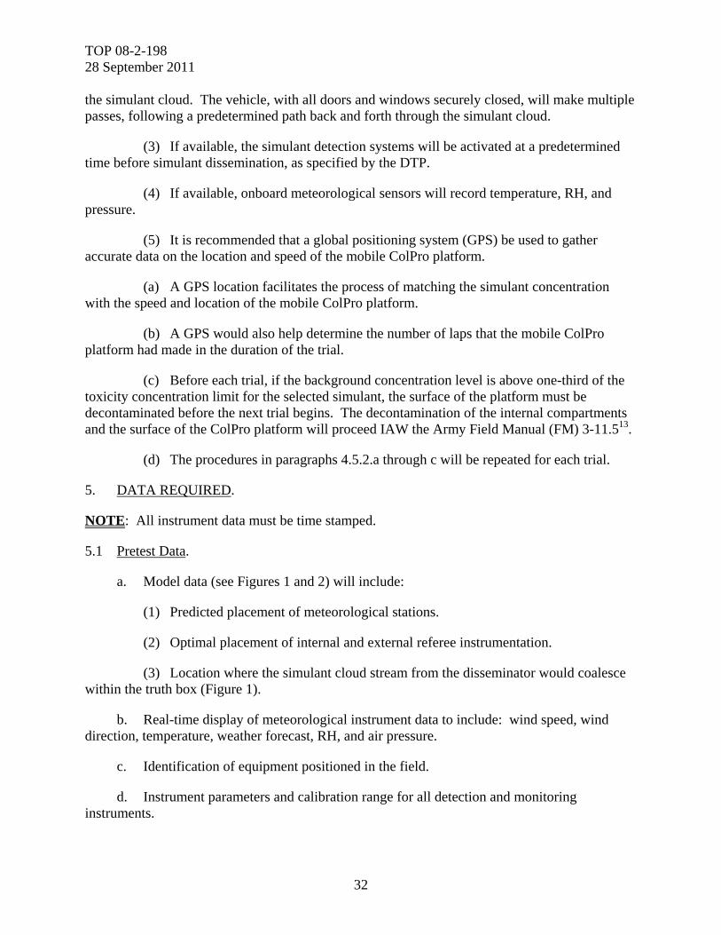
TOP 08-2-198 28 September 2011
32
the simulant cloud. The vehicle, with all doors and windows securely closed, will make multiple passes, following a predetermined path back and forth through the simulant cloud.
(3) If available, the simulant detection systems will be activated at a predetermined time before simulant dissemination, as specified by the DTP.
(4) If available, onboard meteorological sensors will record temperature, RH, and pressure.
(5) It is recommended that a global positioning system (GPS) be used to gather accurate data on the location and speed of the mobile ColPro platform.
(a) A GPS location facilitates the process of matching the simulant concentration with the speed and location of the mobile ColPro platform.
(b) A GPS would also help determine the number of laps that the mobile ColPro platform had made in the duration of the trial.
(c) Before each trial, if the background concentration level is above one-third of the toxicity concentration limit for the selected simulant, the surface of the platform must be decontaminated before the next trial begins. The decontamination of the internal compartments and the surface of the ColPro platform will proceed IAW the Army Field Manual (FM) 3-11.513.
(d) The procedures in paragraphs 4.5.2.a through c will be repeated for each trial.
5. DATA REQUIRED.
NOTE: All instrument data must be time stamped.
5.1 Pretest Data.
a. Model data (see Figures 1 and 2) will include:
(1) Predicted placement of meteorological stations.
(2) Optimal placement of internal and external referee instrumentation.
(3) Location where the simulant cloud stream from the disseminator would coalesce within the truth box (Figure 1).
b. Real-time display of meteorological instrument data to include: wind speed, wind direction, temperature, weather forecast, RH, and air pressure.
c. Identification of equipment positioned in the field.
d. Instrument parameters and calibration range for all detection and monitoring instruments.
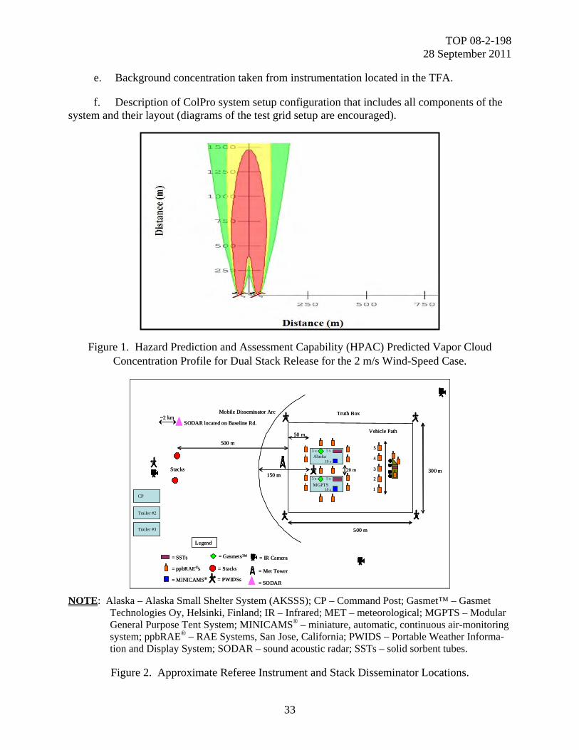
TOP 08-2-198 28 September 2011
33
e. Background concentration taken from instrumentation located in the TFA.
f. Description of ColPro system setup configuration that includes all components of the system and their layout (diagrams of the test grid setup are encouraged).
Figure 1. Hazard Prediction and Assessment Capability (HPAC) Predicted Vapor Cloud Concentration Profile for Dual Stack Release for the 2 m/s Wind-Speed Case.
Truth Box
Alaska
20 m
50 m
300 m
500 m
Stacks
Vehicle Path
3 x
10 x
500 m
Legend
= SSTs
= ppbRAE®s
= MINICAMS®
= Gasmets™
5 x
MGPTS
3 x
10 x
5 x
Mobile Disseminator Arc
150 m
= IR Camera
= Stacks
= PWIDSs
= Met Tower
CP
Trailer #2
Trailer #3
5
4
3
2
1
~2 kmSODAR located on Baseline Rd.
= SODAR
Truth Box
Alaska
20 m
50 m
300 m
500 m
Stacks
Vehicle Path
3 x
10 x
500 m
Legend
= SSTs
= ppbRAE®s
= MINICAMS®
= Gasmets™
5 x
MGPTS
3 x
10 x
5 x
Mobile Disseminator Arc
150 m
= IR Camera
= Stacks
= PWIDSs
= Met Tower
CP
Trailer #2
Trailer #3
5
4
3
2
1
~2 kmSODAR located on Baseline Rd.
= SODAR
NOTE: Alaska – Alaska Small Shelter System (AKSSS); CP – Command Post; Gasmet™ – Gasmet Technologies Oy, Helsinki, Finland; IR – Infrared; MET – meteorological; MGPTS – Modular General Purpose Tent System; MINICAMS® – miniature, automatic, continuous air-monitoring system; ppbRAE® – RAE Systems, San Jose, California; PWIDS – Portable Weather Informa-tion and Display System; SODAR – sound acoustic radar; SSTs – solid sorbent tubes.
Figure 2. Approximate Referee Instrument and Stack Disseminator Locations.
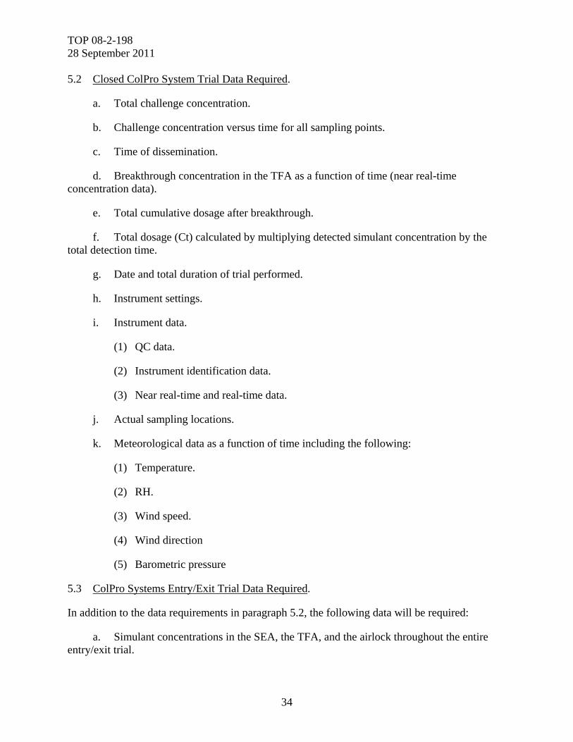
TOP 08-2-198 28 September 2011
34
5.2 Closed ColPro System Trial Data Required.
a. Total challenge concentration.
b. Challenge concentration versus time for all sampling points.
c. Time of dissemination.
d. Breakthrough concentration in the TFA as a function of time (near real-time concentration data).
e. Total cumulative dosage after breakthrough.
f. Total dosage (Ct) calculated by multiplying detected simulant concentration by the total detection time.
g. Date and total duration of trial performed.
h. Instrument settings.
i. Instrument data.
(1) QC data.
(2) Instrument identification data.
(3) Near real-time and real-time data.
j. Actual sampling locations.
k. Meteorological data as a function of time including the following:
(1) Temperature.
(2) RH.
(3) Wind speed.
(4) Wind direction
(5) Barometric pressure
5.3 ColPro Systems Entry/Exit Trial Data Required.
In addition to the data requirements in paragraph 5.2, the following data will be required:
a. Simulant concentrations in the SEA, the TFA, and the airlock throughout the entire entry/exit trial.
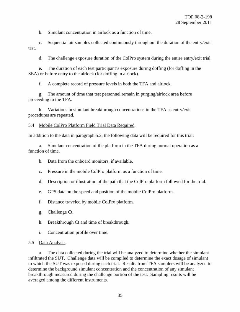
TOP 08-2-198 28 September 2011
35
b. Simulant concentration in airlock as a function of time.
c. Sequential air samples collected continuously throughout the duration of the entry/exit test.
d. The challenge exposure duration of the ColPro system during the entire entry/exit trial.
e. The duration of each test participant’s exposure during doffing (for doffing in the SEA) or before entry to the airlock (for doffing in airlock).
f. A complete record of pressure levels in both the TFA and airlock.
g. The amount of time that test personnel remain in purging/airlock area before proceeding to the TFA.
h. Variations in simulant breakthrough concentrations in the TFA as entry/exit procedures are repeated.
5.4 Mobile ColPro Platform Field Trial Data Required.
In addition to the data in paragraph 5.2, the following data will be required for this trial:
a. Simulant concentration of the platform in the TFA during normal operation as a function of time.
b. Data from the onboard monitors, if available.
c. Pressure in the mobile ColPro platform as a function of time.
d. Description or illustration of the path that the ColPro platform followed for the trial.
e. GPS data on the speed and position of the mobile ColPro platform.
f. Distance traveled by mobile ColPro platform.
g. Challenge Ct.
h. Breakthrough Ct and time of breakthrough.
i. Concentration profile over time.
5.5 Data Analysis.
a. The data collected during the trial will be analyzed to determine whether the simulant infiltrated the SUT. Challenge data will be compiled to determine the exact dosage of simulant to which the SUT was exposed during each trial. Results from TFA samplers will be analyzed to determine the background simulant concentration and the concentration of any simulant breakthrough measured during the challenge portion of the test. Sampling results will be averaged among the different instruments.
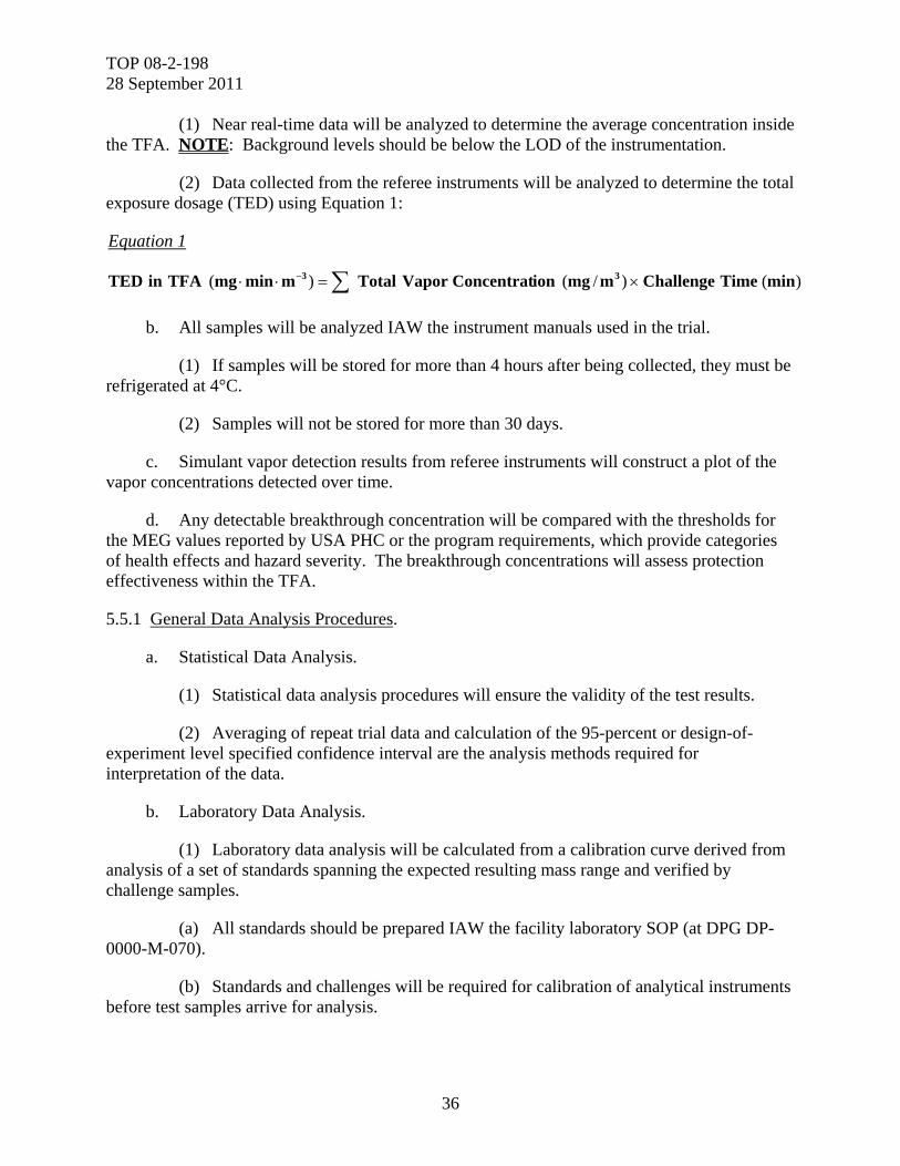
TOP 08-2-198 28 September 2011
36
(1) Near real-time data will be analyzed to determine the average concentration inside the TFA. NOTE: Background levels should be below the LOD of the instrumentation.
(2) Data collected from the referee instruments will be analyzed to determine the total exposure dosage (TED) using Equation 1:
Equation 1
)()/()( minTimeChallengemmgionConcentratVaporTotalmminmgTFAinTED 33
b. All samples will be analyzed IAW the instrument manuals used in the trial.
(1) If samples will be stored for more than 4 hours after being collected, they must be refrigerated at 4°C.
(2) Samples will not be stored for more than 30 days.
c. Simulant vapor detection results from referee instruments will construct a plot of the vapor concentrations detected over time.
d. Any detectable breakthrough concentration will be compared with the thresholds for the MEG values reported by USA PHC or the program requirements, which provide categories of health effects and hazard severity. The breakthrough concentrations will assess protection effectiveness within the TFA.
5.5.1 General Data Analysis Procedures.
a. Statistical Data Analysis.
(1) Statistical data analysis procedures will ensure the validity of the test results.
(2) Averaging of repeat trial data and calculation of the 95-percent or design-of-experiment level specified confidence interval are the analysis methods required for interpretation of the data.
b. Laboratory Data Analysis.
(1) Laboratory data analysis will be calculated from a calibration curve derived from analysis of a set of standards spanning the expected resulting mass range and verified by challenge samples.
(a) All standards should be prepared IAW the facility laboratory SOP (at DPG DP-0000-M-070).
(b) Standards and challenges will be required for calibration of analytical instruments before test samples arrive for analysis.

TOP 08-2-198 28 September 2011
37
(2) A chemical analysis procedure will be conducted with an appropriate number of standards, blanks, and analytical controls (5 percent of the samples as a minimum). These actions will ensure that the analytical procedure is reliable and will document the precision obtained from the analysis of the test samples.
c. Meteorological data will be plotted as a function of time.
5.5.2 Descriptive Overview of Data Analysis for Each Trial.
5.5.2.1 RTM and NRTM Data Analysis.
a. Real-time TFA concentrations will be compared with exposure guideline values.
(1) Near real-time data will be analyzed to determine the average concentration inside the TFA.
(2) The data from this analysis will be compiled into a table that lists the TFA concentration values.
(3) These values will be compared with the exposure guideline values listed either in the MEG values reported by USA PHC or in the program requirement.
(4) If any TFA concentration values exceed these guidelines, a failure will be noted.
b. Total vapor concentration from NRTM will be obtained as shown in Equation 2:
Equation 2
L10
mminTimeSampling
min
LFlowrateAir
CycleRefereeNRTperDetectedmg10
mgmgMass
m
mgionConcentratVaporTotal
3
3
6
3
c. The RTM and NRTM data sets will generate a concentration-of-simulant-versus-time curve. Figures 3 through 5 show examples of these concentration curves.
5.5.2.2 Protection Factor (PF).
a. In order to correlate historical data from previous field trials with data from new trials, the PF of the SUT will be calculated using the following steps:
(1) The PF will be calculated by subtracting the background from the breakthrough dosage and dividing the total challenge dosage by the net TFA dosage (Equation 3).
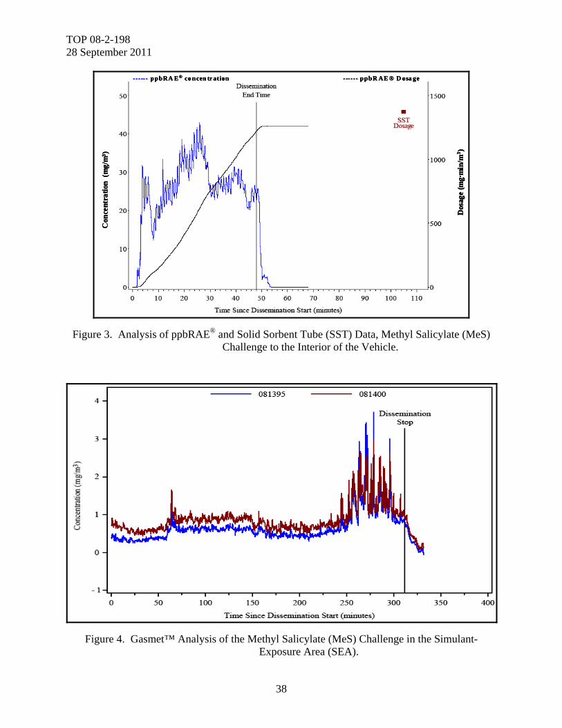
TOP 08-2-198 28 September 2011
38
------ ppbRA E® co ncen tr ation ------ ppbR AE ® D osa ge
Dos
age
(mg·
min
/m3 )
Con
cent
rati
on (
mg/
m3 )
- ----- ppbRA E® co ncen tr ation ------ ppbR AE ® D osa ge
Dos
age
(mg·
min
/m3 )
Con
cent
rati
on (
mg/
m3 )
- ----- ppbRA E® co ncen tr ation ------ ppbR AE ® D osa ge
Dos
age
(mg·
min
/m3 )
Con
cent
rati
on (
mg/
m3 )
Figure 3. Analysis of ppbRAE® and Solid Sorbent Tube (SST) Data, Methyl Salicylate (MeS) Challenge to the Interior of the Vehicle.
Figure 4. Gasmet™ Analysis of the Methyl Salicylate (MeS) Challenge in the Simulant-Exposure Area (SEA).
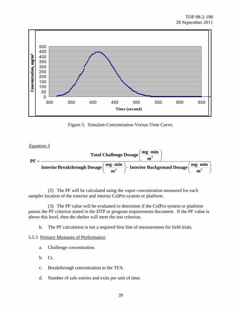
TOP 08-2-198 28 September 2011
39
Con
cent
rati
on, m
g/m
3
050
100150200250300350400450500
300 350 400 450 500 550 600 650Time (second)
Con
cent
rati
on, m
g/m
3
050
100150200250300350400450500
300 350 400 450 500 550 600 650Time (second)
Figure 5. Simulant-Concentration-Versus-Time Curve.
Equation 3
33
3
m
minmgDosageBackgroundInterior
m
minmgDosageghBreakthrouInterior
m
minmgDosageChallengeTotal
PF
(2) The PF will be calculated using the vapor concentration measured for each sampler location of the exterior and interior ColPro system or platform.
(3) The PF value will be evaluated to determine if the ColPro system or platform passes the PF criterion stated in the DTP or program requirements document. If the PF value is above this level, then the shelter will meet the test criterion.
b. The PF calculation is not a required first line of measurement for field trials.
5.5.3 Primary Measures of Performance.
a. Challenge concentration.
b. Ct.
c. Breakthrough concentration to the TFA.
d. Number of safe entries and exits per unit of time.
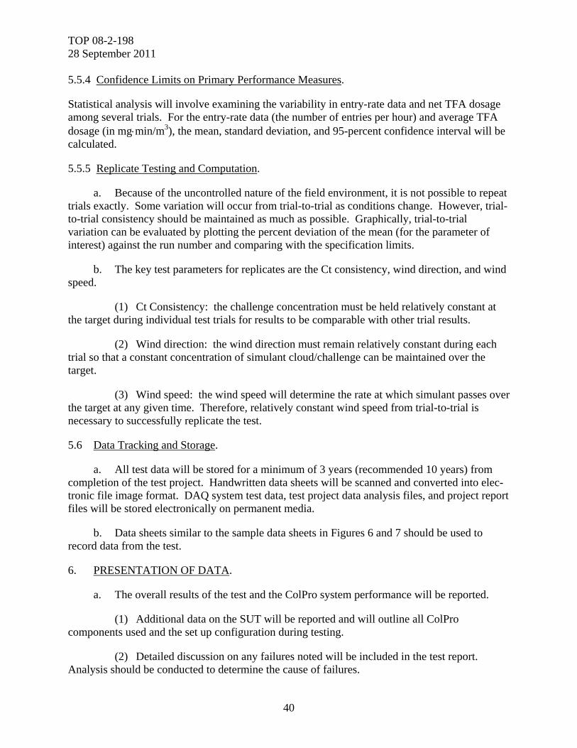
TOP 08-2-198 28 September 2011
40
5.5.4 Confidence Limits on Primary Performance Measures.
Statistical analysis will involve examining the variability in entry-rate data and net TFA dosage among several trials. For the entry-rate data (the number of entries per hour) and average TFA dosage (in mgmin/m3), the mean, standard deviation, and 95-percent confidence interval will be calculated.
5.5.5 Replicate Testing and Computation.
a. Because of the uncontrolled nature of the field environment, it is not possible to repeat trials exactly. Some variation will occur from trial-to-trial as conditions change. However, trial-to-trial consistency should be maintained as much as possible. Graphically, trial-to-trial variation can be evaluated by plotting the percent deviation of the mean (for the parameter of interest) against the run number and comparing with the specification limits.
b. The key test parameters for replicates are the Ct consistency, wind direction, and wind speed.
(1) Ct Consistency: the challenge concentration must be held relatively constant at the target during individual test trials for results to be comparable with other trial results.
(2) Wind direction: the wind direction must remain relatively constant during each trial so that a constant concentration of simulant cloud/challenge can be maintained over the target.
(3) Wind speed: the wind speed will determine the rate at which simulant passes over the target at any given time. Therefore, relatively constant wind speed from trial-to-trial is necessary to successfully replicate the test.
5.6 Data Tracking and Storage.
a. All test data will be stored for a minimum of 3 years (recommended 10 years) from completion of the test project. Handwritten data sheets will be scanned and converted into elec-tronic file image format. DAQ system test data, test project data analysis files, and project report files will be stored electronically on permanent media.
b. Data sheets similar to the sample data sheets in Figures 6 and 7 should be used to record data from the test.
6. PRESENTATION OF DATA.
a. The overall results of the test and the ColPro system performance will be reported.
(1) Additional data on the SUT will be reported and will outline all ColPro components used and the set up configuration during testing.
(2) Detailed discussion on any failures noted will be included in the test report. Analysis should be conducted to determine the cause of failures.
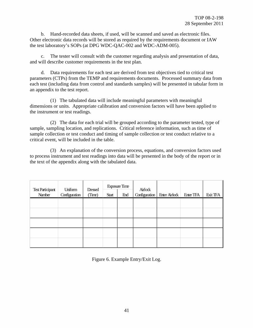
TOP 08-2-198 28 September 2011
41
b. Hand-recorded data sheets, if used, will be scanned and saved as electronic files. Other electronic data records will be stored as required by the requirements document or IAW the test laboratory’s SOPs (at DPG WDC-QAC-002 and WDC-ADM-005).
c. The tester will consult with the customer regarding analysis and presentation of data, and will describe customer requirements in the test plan.
d. Data requirements for each test are derived from test objectives tied to critical test parameters (CTPs) from the TEMP and requirements documents. Processed summary data from each test (including data from control and standards samples) will be presented in tabular form in an appendix to the test report.
(1) The tabulated data will include meaningful parameters with meaningful dimensions or units. Appropriate calibration and conversion factors will have been applied to the instrument or test readings.
(2) The data for each trial will be grouped according to the parameter tested, type of sample, sampling location, and replications. Critical reference information, such as time of sample collection or test conduct and timing of sample collection or test conduct relative to a critical event, will be included in the table.
(3) An explanation of the conversion process, equations, and conversion factors used to process instrument and test readings into data will be presented in the body of the report or in the text of the appendix along with the tabulated data.
Test Participant Number
Uniform Configuration
Dressed (Time)
Exposure Time Airlock
Configuration Enter Airlock Enter TFA Exit TFA Start End
Figure 6. Example Entry/Exit Log.
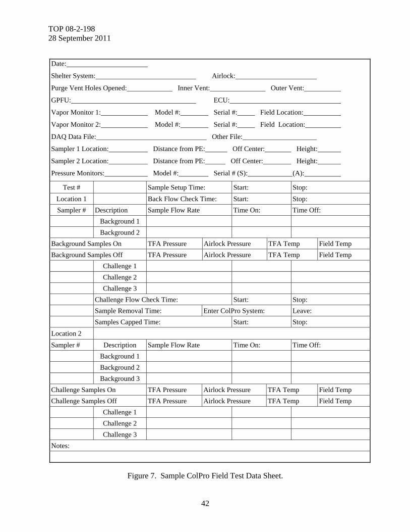
TOP 08-2-198 28 September 2011
42
Figure 7. Sample ColPro Field Test Data Sheet.
Date:
Shelter System: Airlock:
Purge Vent Holes Opened: Inner Vent: Outer Vent:
GPFU: ECU:
Vapor Monitor 1: Model #: Serial #: Field Location:
Vapor Monitor 2: Model #: Serial #: Field Location:
DAQ Data File: Other File:
Sampler 1 Location: Distance from PE: Off Center: Height:
Sampler 2 Location: Distance from PE: Off Center: Height:
Pressure Monitors: Model #: Serial # (S): (A):
Test # Sample Setup Time: Start: Stop:
Location 1 Back Flow Check Time: Start: Stop:
Sampler # Description Sample Flow Rate Time On: Time Off:
Background 1
Background 2
Background Samples On TFA Pressure Airlock Pressure TFA Temp Field Temp
Background Samples Off TFA Pressure Airlock Pressure TFA Temp Field Temp
Challenge 1
Challenge 2
Challenge 3
Challenge Flow Check Time: Start: Stop:
Sample Removal Time: Enter ColPro System: Leave:
Samples Capped Time: Start: Stop:
Location 2
Sampler # Description Sample Flow Rate Time On: Time Off:
Background 1
Background 2
Background 3
Challenge Samples On TFA Pressure Airlock Pressure TFA Temp Field Temp
Challenge Samples Off TFA Pressure Airlock Pressure TFA Temp Field Temp
Challenge 1
Challenge 2
Challenge 3
Notes:
TOP 08-2-198 28 September 2011
43
e. The data will be treated statistically on the basis of the parameters and criteria from the requirement documents and the summarized data, and statistical derivations will be presented in tabular form in the body of the test report.
(1) For each parameter, the tables will present the statistically treated data and derivations together with verification criteria values or ranges from the requirement documents.
(2) Appropriate graphics will show the distribution of data points for comparison of test values with critical values from the requirements documents.
f. The reliability and accuracy of the test data will be evaluated by comparing test results with the results from the control and standard samples and readings. Statistical tests for data reliability and accuracy will be applied to the data. Reliability and accuracy indices will be presented in the body of the test report along with the summarized data.
g. Textual explanations, TIRs, time lines, photographic evidence, and diagrams, among other data, will be presented in the body of the test report to explain any data anomalies, gaps, and/or other deficiencies. The test team and preparer of the test report will provide an unbiased evaluation of the procedures employed and the reliability and accuracy of the data.
h. Statistical methods used in processing and evaluating the reliability and accuracy of the data will be described in an appendix to the test report.
i. All of the data presentation formats will accommodate the analysis to determine whether the test system design and performance satisfy the CTPs from the requirements documents. As part of the data analysis, a determination will be made as to whether the data are adequate for that determination.

TOP 08-2-198 28 September 2011
44
(This page is intentionally blank.)
TOP 08-2-198 28 September 2011
A-1
APPENDIX A. ABBREVIATIONS.
AKSSS Alaska Small Shelter System
ANSI NCSL American National Standards Institute National Conference of Standards La-boratories
AR Army Regulation
ATEC US Army Test and Evaluation Command
CBR chemical, biological, and radiological
CDD Capabilities Development Document
CFD computational fluid dynamics
ConOps concept of operations
ColPro collective protection
CP Command Post
CPD Capabilities Production Document
Ct concentration × time
CTPs critical test parameter
CWA chemical warfare agent
DA Department of Army
DAQ data acquisition
DT developmental test
DTP detailed test plan
DPG Dugway Proving Ground
EA environmental assessment
ECU electronic control unit
EDP Event Design Plan
EIALC environmental impact assessment for life cycle
EIS environmental impact statement
EMT emergency medical technician
FM Field Manual
GPS global positioning system
TOP 08-2-198 28 September 2011
A-2
APPENDIX A. ABBREVIATIONS.
HHA Health Hazard Assessment
HPAC hazard prediction and assessment capability
HUC human use committee
IAW in accordance with
IHP industrial hygiene plan
IPE individual protection equipment
IR infrared
ISO International Organization for Standardization
LOD limit of detection
LPA low-pressure alarm
MEG military exposure guide
MeS methyl salicylate
MGPTS modular general purpose tent system
MINICAMS® a miniature, automatic, continuous air-monitoring system
MOPP mission-oriented protective posture
MSDS material safety data sheet
NEPA National Environmental Policy Act
NRTM near real-time monitor
OM operator’s manual
OT operational test
PAM pamphlet
PF protection factor
PPE personal protective equipment
PWIDS portable weather information and display systems
QA quality assurance
QC quality control
REC record of environmental consideration
RH relative humidity
RTM real-time monitor
TOP 08-2-198 28 September 2011
A-3
APPENDIX A. ABBREVIATIONS.
SAR Safety Assessment Report
SCBA self-contained breathing apparatus
SCIPUFF Second-Order Closure Integrated PUFF
SEA simulant exposure area
SEP System Evaluation Plan
SODAR sound acoustic radar
SOP Standing Operating Procedure
SPS System Performance Specification
SR safety release
SSP system support package
SSPL SSP list
SST solid sorbent tube
SUT system under test
TB technical bulletin
TED total exposure dosage
TEMP Test and Evaluation Master Plan
TFA toxic free area
TI technical instruction
TICN test item control number
TIR test incident report
TM technical manual
TO technical order
TOP Test Operations Procedure
USA PHC US Army Public Health Command
WPL worker population limit

TOP 08-2-198 28 September 2011
A-4
(This page is intentionally blank.)
TOP 08-2-198 28 September 2011
B-1
APPENDIX B. REFERENCES.
1. DA PAM 385-61, Toxic Chemical Agent Safety Standards, 17 December 2008.
2. AR 385-10, The Army Safety Program, 27 August 2007 (Rapid Action Revision 001, 3 September 2009).
3. DPG, Methodology Investigation Report for the Simulant Test Platform (STP) Field Test, ATEC Project Number 2006-DT-DPG-CBPDX-D1999, West Desert Test Center Document Number WDTC-MR-09-118, April 2009.
4. Introduction to FLUENT 12.0, 28 April 2009.
5. DPG, Methodology Investigation Report for Collective Protection (ColPro) Airflow Mapping II, WDTC-MR-08-062, October 2008.
6. DPG, Final Test Report for the Characterization and Validation of the Active Standoff Chamber (ASC), WDTC-TR-09-024, September 2009.
7. DPG, Final Test Report for the Characterization and Validation of the Joint Ambient Breeze Tunnel (JABT), WDTC-TR-08-017, March 2008.
8. ANSI NCSL Z540-3, Requirements for the Calibration of Measuring and Test Equipment, National Conference of Standards Laboratories, 1 January 2006.
9. ISO 10012:2003, Measurement Management Systems - Requirements for Measurement Processes and Measuring Equipment, 1 April 2003.
10. TB-750-25, Army Test Measurement and Diagnostic Equipment (TMDE) Calibration and Repair Support (C&RS) Program Manual, 1 March 1997.
11. TI 4733-OD/1, Calibration Requirements Marine Corps Test, Measurement and Diagnostic Equipment Calibration and Maintenance Program, 31 March 2009.
12. TO 00-20-14, Air Force Metrology and Calibration Program, 30 June 2007.
13. FM 3-11.5, Marine Corps Reference Publication (MCRP) 3-37.3/Navy Tactics, Techniques, and Procedures (NTTP) 3-11.26/Air Force Tactics, Techniques, and Procedures (AFTTP) 3-2.60, Multiservice Tactics, Techniques, and Procedures for Chemical, Biological, Radiological, and Nuclear Decontamination, 4 April 2006.

TOP 08-2-198 28 September 2011
B-2
(This page is intentionally blank.)
TOP 08-2-198 28 September 2011
C-1
APPENDIX C. DUGWAY PROVING GROUND (DPG) STANDING OPERATING PROCEDURES (SOPS).
a. To obtain a current copy of the DPG SOPs, an organization’s point of contact (POC) will make a written request to their DPG counterpart requesting access to the specific DPG SOP. The DPG POC will then follow internal guidelines to obtain a copy of the requested SOP for the or-ganization. NOTE: The request for a copy of DPG SOPs cannot be made by a contractor.
b. The organization making the request must:
(1) Specify whether an electronic or printed copy of the DPG SOP is required.
(2) List the names of the individuals and groups that will have access to the SOPs.
(3) Provide justification for request.
TOP 08-2-198 28 September 2011
C-2
APPENDIX C. DUGWAY PROVING GROUND (DPG) STANDING OPERATING PROCEDURES (SOPS).
1. DPG SOP WDC-CL-044R, Chemical Agent Monitoring _GC, GB, GD, GF, HD, Lewiste, HN1, HN3, and VX _Using Field MINICAMS, Revision 4, 20 September 2009.
2. DPG SOP WDC-ANA-009, Safety Air Monitoring Using Solid Sorbent Tubes, Revision 4, 14 April 2009.
3. DPG SOP WDC-QAC-003R, CHWSF Quality Assurance Program Plan, Revision 1, 02 February 2009.
4. DPG SOP WDC-ANA-034, Near Real-Time Chemical Agent Monitoring, Revision 5, 05 June 2009.
5. DPG SOP DP-0000-M-070, Toxic Agent Operations and Safety, Revision 10, 06 April 2009.
6. DPG SOP WDC-ANA-004, Procedures for the Analysis of Liquid Samples by Gas Chromatographic Methods, Revision 5, 01 October 2009.
7. DPG SOP WDC-ANA-032, Analysis of Chemical Agents GA, GD, GF, and VX on DAAMS Tubes by Gas Chromatography, Revision 4, 11 February 2009.
8. DPG SOP WDC-ANA-033, Analysis of Chemical Agents HD, HN-1, and HN-3 on DAAMS Tubes by Gas Chromatography, Revision 4, 06 April 2009.
9. DPG SOP WDC-ANA-039, Multicomponent FTIR Gas Analyzer GASMET™ DX-4000 Calibration and Operation, Revision 1, 01 October 2009.
10. DPG SOP WDC-WIN-009, Work Instruction for the Extraction of Chemical Agent or Simulant from Solid Sorbent Tubes, Revision 2, 11 December 2008.
11. DPG SOP WDC-WIN-006, Preparation and Testing of Solid Sorbent Tubes, Revision 3, 19 November 2009.
12. DPG SOP DP-0000-D-216, Preparation, Calibration and Operation of Dissemination Equipment, Revision 5, 03 March 2009.
13. DPG SOP WDC-ADM-009, Sample Management, Revision 3, 16 July 2009.
14. DPG SOP WDC-ADM-017, Analytical Method Requirements, Revision 3, 19 March 2009.
15. DPG SOP DP-0000-M-230, Simulant Dissemination, Revision 4, 29 January 2009.
TOP 08-2-198 28 September 2011
C-3
APPENDIX C. DUGWAY PROVING GROUND (DPG) STANDING OPERATING PROCEDURES (SOPS).
16. DPG SOP WDC-ADM-005, Chemical Test Division Reports, Record Keeping, and Data Management, Revision 4, 06 April 2009.
17. DPG SOP WDC-CL-052R, Chemical Agents in DAAMS by GC, Revision 3, 14 September 2009.
18. DPG SOP WDC-ADM-015, Review of Safety Air Monitoring Analytical Data, Revision 4, 01 November 2009.

TOP 08-2-198 28 September 2011
C-4
(This page is intentionally blank.)
TOP 08-2-198 28 September 2011
D-1
APPENDIX D. CAPABILITY AREA PROCESS ACTION TEAM (CAPAT) SIGNATURES.
Figure D-1. Page 1 of CAPAT signature sheet.
COLPRO CAP AT recommends approval ofthe Test Operations Procedure (TOP) 8-2-198 COLPRO Field Testing. If an organization non-concurs, a dissenting position paper
will be attached.
CONCURRENCE SHEET
Darren Jolley Steve Tackett
Collective Protection Commodity Area US Army Test and Evaluation Command
Process Action Team (CAP AT) Chair (ATEC)/U.S. Anny Evaluation Command
/l (AEC)
lL. A~c{Jf ~turc l~t
ate Signature Date
Bob Burkholder Ann Gossage
Air Force Operational Test and Evaluation· Marine Corps Operational Test & Evaluation Center (AFOTEC) Activity (MCOTEA)
Signature Date Signature Date
LCDR Gerrod Seifert Deb Shuping
Commander Operational Test and Evaluation Test and Evaluation Office (TEO) Force (COMOPTEVFOR)
Signature ' Date Signature Date
Juan Vitali Michael Roberts
Joint Program Executive Oftice for Chemical Joint Science and Technology Office (JSTO) Biological Defense (JPEO-CBD)
Signature Date Signature Date
Greg Marshall Joint Requirements Office (JRO) for Chemical, Biological, Radiological, and Nuclear Defense
Signature Date

TOP 08-2-198 28 September 2011
D-2
APPENDIX D. CAPABILITY AREA PROCESS ACTION TEAM (CAPAT) SIGNATURES.
Figure D-2. Page 2 of CAPAT signature sheet.
COLPRO CAP AT recommends approval of the Test Operations Procedure (TOP) 8-2-198 COLPRO Field Testing. If an organization non-concurs, a dissenting position paper will be attached.
CONCURRENCE SHEET
Darren Jolley Steve Tackett Collective Protection Commodity Area Process Action US Army Test and Evaluation Team(CAPAT) Chair Command (ATEC)/U.S. Army
Evaluation Command (AEC)
Signature Date Signature Date
Bob Burkholder Ann Gossage Air Force Operational Test and Evaluation Center Marine Corps Operational Test & (AFOTEC) Evaluation Activity (MCOTEA)
1 2/17/ 2 009
X Robert L. Burkholder Signature Date Robert L.. Buri<hok:te r HQ A FOTBC C B/For"C>e Pro<:ecc ion PM .
LCDR Gerrod Seifert Deb Shuping Commander Operational Test and Evaluation Force Test and Evaluation Office (TEO) (COMOPTE~OR)
Signature Date Signature Date
Juan Vitali Michael Roberts Joint Program Executive Office for Chemical Joint Science and Technology Biological Defense (JPEO-CBD) Office (JSTO)
Signature Date Signature Date
Greg Marshall Joint Requirements Office (JRO) for Chemical, Biological, Radiological, and Nuclear Defense
TOP 08-2-198 28 September 2011
D-3
APPENDIX D. CAPABILITY AREA PROCESS ACTION TEAM (CAPAT) SIGNATURES.
Figure D-3. Page 3 of CAPAT signature sheet.
Test Operations Procedure (TOP)
8-2-198 COLPRO Field Testing
CONCURRENCE:
Darren Jolley Deb Shuping !
Collective Protection Commodity Area Test & Evaluation Office (TEO) Process Action Team (CAP AT) Chair
IQL / Ai,A/~ 0 ~? , .I
Shtnature Date Signature Date
Mike Helinski Ann Gossage Army Materiel Systems Analysis Agency Marine Corps Operational Test & Evaluation (AMSAA) Activity (MCOTEA)
Si1mature Date Si1mature Date ~
Terrance Westerfield Greg Marshall U. S. Army Test and Evaluation Command Joint Requirements Office (JRO) for (ATEC)/U.S. Army Evaluation Command Chemical, Biological, Radiological, and (AEC) Nuclear Defense
Shmature Date Si1mature Date
LCDR GERROD SEIFERT Christine Crabill ChemicaVBiological Defense Operational Director Of Operational Test & Evaluation Test and Evaluation Force (DOT&E) (OSD Oversight) (COMOPTEVFOR)
Simature Date Si1mature Date
TOP 08-2-198 28 September 2011
D-4
APPENDIX D. CAPABILITY AREA PROCESS ACTION TEAM (CAPAT) SIGNATURES.
Figure D-4. Page 4 of CAPAT signature sheet.
COLPRO CAP AT recommends approval of the Test Operations Procedure (TOP) 8-2-198 COLPRO Field Testing. If an organization non-concurs, a dissenting position paper will be attached.
CONCURRENCE SHEET
Darren Jolley Steve Tackett Collective Protection Commodity Area US Army Test and Evaluation Command Process Action Team (CAP AT) Chair (ATEC)IU.S. Army Evaluation Command
(AEC)
Signature Date Signature Date
Bob Burkholder Ann Gossage Air Force Operational Test and Evaluation Marine Corps Operational Test & Evaluation Center (AFOTEC) Activity (MCOTEA}
k::?~ ~ s~eto\ 0
Signature Date Signature Date . LCDR Gerrod Seifert Deb Shuping
Commander Operational Test and Test and Evaluation Office (TEO) Evaluation Force (COMOPTEVFOR)
\-Signature Date Signature Date
Juan Vitali Michael Roberts Joint Program Executive Office for Joint Science and Technology Office (JSTO) Chemical Biological Defense (JPEO-CBD)
Signature Date Signature Date
Valerie L. Hasberry, Lt Col, USAF Chief, Capabilities Integration Branch Joint Requirements Office (JRO)- CBRN Defense
S ignature Date
TOP 08-2-198 28 September 2011
D-5
APPENDIX D. CAPABILITY AREA PROCESS ACTION TEAM (CAPAT) SIGNATURES.
Figure D-5. Page 5 of CAPAT signature sheet.
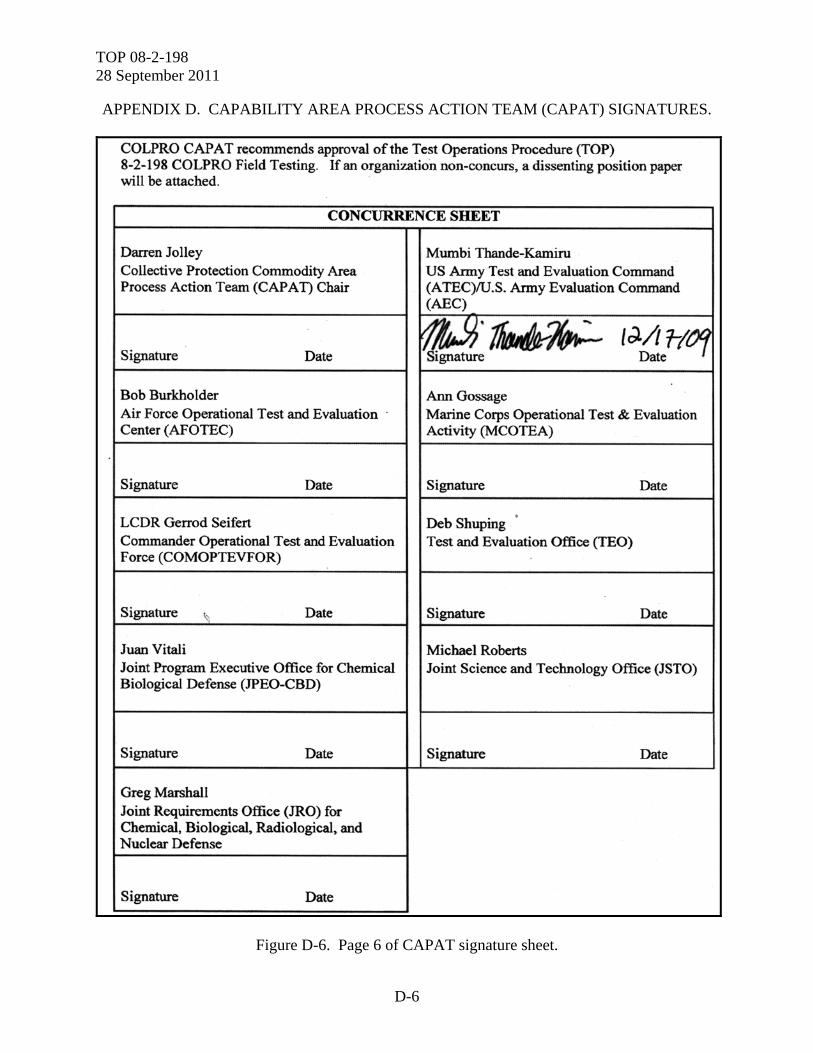
TOP 08-2-198 28 September 2011
D-6
APPENDIX D. CAPABILITY AREA PROCESS ACTION TEAM (CAPAT) SIGNATURES.
Figure D-6. Page 6 of CAPAT signature sheet.
COLPRO CAP AT recommends approval of the Test Operations Procedure (TOP) 8-2-198 COLPRO Field Testing. If an organization non-concurs, a dissenting position paper will be attached.
CONCURRENCE SHEET
Darren Jolley Mumbi Thande-Kamiru Collective Protection Commodity Area US Army Test and Evaluation Command Process Action Team (CAP An Chair (ATEC)/U.S. Army Evaluation Command
(AEC)
Signature Date ~·~· Signature tJ./1 t-lq
Date
Bob Burkholder Ann Gossage Air Force Operational Test and Evaluation · Marine Corps Operational Test & Evaluation Center (AFOTEC) Activity (MCOTEA)
Signature Date Signature Date
LCDR Gerrod Seifert Deb Shuping .
Commander Operational Test and Evaluation Test and Evaluation Office (TEO) Force (COMOPTEVFOR)
Signature ~ Date Signature Date
Juan Vitali Michael Roberts Joint Program Executive Office for Chemical Joint Science and Technology Office (JSTO) Biological Defense (JPEO-CBD)
Signature Date Signature Date
Greg Marshall Joint Requirements Office (JRO) for Chemical, Biological, Radiological, and Nuclear Defense
Signature Date
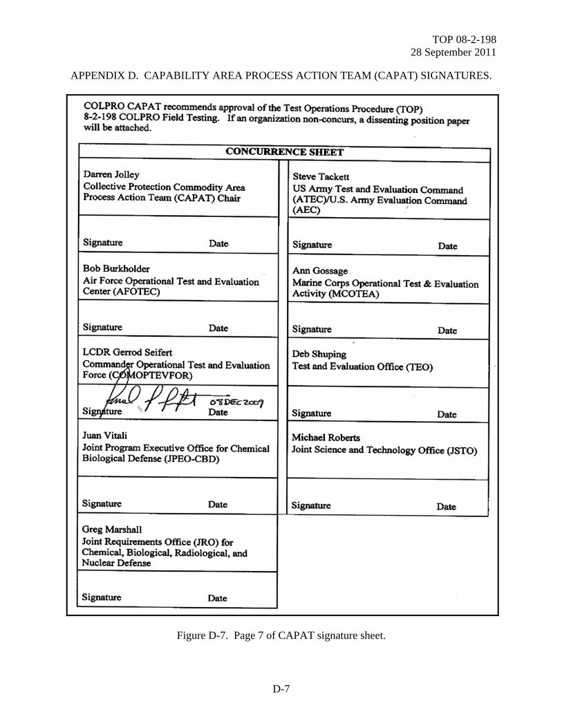
TOP 08-2-198 28 September 2011
D-7
APPENDIX D. CAPABILITY AREA PROCESS ACTION TEAM (CAPAT) SIGNATURES.
Figure D-7. Page 7 of CAPAT signature sheet.
COLPRO CAP AT recommends approval of the Test Operations Procedure (TOP) 8-2-198 COLPRO Field Testing. If an organization non-concurs, a dissenting position paper will be attached.
CONCURRENCE SHEET
Darren Jolley Steve Tackett Collective Protection Commodity Area US Army Test and Evaluation Command Process Action Team (CAPAl) Chair (ATEC)IU.S. Army Evaluation Command
(AEC) '
Signature Date Signature Date
Bob Burkholder Ann Gossage Air Force Operational Test and Evaluation Marine Corps Operational Test & Evaluation Center (AFOTEC) Activity (MCOTEA)
Signature Date Signature Date . LCDR Gerrod Seifert Deb Shuping Comm(~~perational Test and Evaluation Test and Evaluation Office (TEO) Force ( OPTEVFOR)
ip,t~~c~ s ture ~ Date Signature Date
Juan Vitali Michael Roberts Joint Program Executive Office for Chemical Joint Science and Teclmology Office (JSTO) Biological Defense (JPEO-CBD)
Signature Date Signature Date
Greg Marshall Joint Requirements Office (JRO) for Chemical, Biological, Radiological, and Nuclear Defense
Signature Date
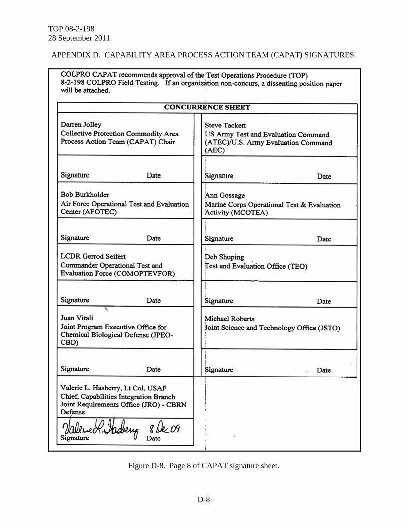
TOP 08-2-198 28 September 2011
D-8
APPENDIX D. CAPABILITY AREA PROCESS ACTION TEAM (CAPAT) SIGNATURES.
Figure D-8. Page 8 of CAPAT signature sheet.
COLPRO CAP AT recommends approval of the Test Operations Procedure (TOP) 8-2-198 COLPRO Field Testing. If an organi7~tion non--concurs, a dissenting position paper will be attached.
I
CONC~NCESHEET
Darren Jolley Steve Tackett Collective Protection Commodity Area ps Army Test and Evaluation Command Process Action Team (CAP AT) Chair (ATEC)/U.S. Army Evaluation Command
(AEC) i l
Signature Date Signature '
Date
i Bob Burkholder .lA.nn Gossage Air Force Operational Test and Evaluation Marine Corps Operational Test & Evaluation Center (AFOTEC) Activity (MCOTEA)
l Signature Date ~ignature Date
! LCDR Gerrod Seifert peb Shuping . Commander Operational Test and 'rest and Evaluation Office (TEO) Evaluation Force (COMOPTEVFOR) :
: I
I '
Signature Date ' Signature Date ~
Juan Vitali Michael Roberts Joint Program Executive Office for ~oint Science and Technology Office (JSTO) Chemical Biological Defense (JPEO-
1 CBD) '
i i
Signature Date ~ignature Date
Valerie L. Hasberry, Lt Col, USAF I Chief. Capabilities Integration Branch ' Joint Requirements Office (JRO) - CBRN !
Defense '
?J~wW.J/Jt4Ju <t~di ' Signature lj Date :
i
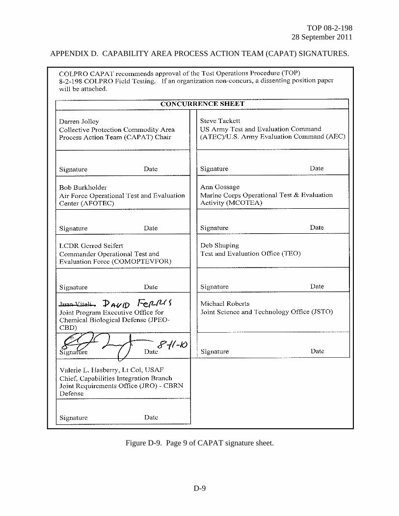
TOP 08-2-198 28 September 2011
D-9
APPENDIX D. CAPABILITY AREA PROCESS ACTION TEAM (CAPAT) SIGNATURES.
Figure D-9. Page 9 of CAPAT signature sheet.
COLPRO CAP AT recommends approval ofthe Test Operations Procedure (TOP) 8-2- 198 COLPRO Field Testing. If an organization non-concurs, a dissenting position paper will be attached.
CONCURRENCE SHEET
Darren Jolley Steve Tackett Collective Protection Commodity Area US Army Test and Evaluation Command Process Action Team (CAP AT) Chair (A TEC)/U.S. Army Evaluation Command (AEC)
Signature Date Signature Date
Bob Burkholder Ann Gossage Air Force Operational Test and Evaluation Marine Corps Operational Test & Evaluation Center (AFOTEC) Activity (MCOTEA)
Signature Date Signature Date
LCDR Gerrod Seifert Deb Shuping Commander Operational Test and Test and Evaluation Office (TEO) Evaluation Force (COMOPTEVFOR)
Signature Date Signature Date
J.ua~ ~~~i-. J> Pt-1/ID FefLfU~ Michael Roberts Joint Program Executive Office for Joint Science and Technology Office (JSTO) Chemical Biological Defense (JPEO-CBD)
6£Xl I ~ R-/1-10 s~, -(; Signature Date tgna re Date
v-
Valerie L. Hasberry, Lt Col, USAF Chief, Capabilities Integration Branch Joint Requirements Office (JRO) - CBRN Defense
Signature Date
TOP 08-2-198 28 September 2011
D-10
(This page is intentionally blank.)
TOP 08-2-198 28 September 2011
E-1
APPENDIX E. DEPARTMENT OF DEFENSE (DOD) TEST AND EVALUATION STANDARD ENDORSEMENT.
Figure E-1. Page 1 of DoD Test and Evaluation Standard endorsement.
DUSA-TE
DEPARTMENT OF THE ARMY OFFICE OF THE DEPUTY UNDER SECRETARY OF THE ARMY
102 ARMY PENTAGON WASHINGTON, DC 20310.0102
MEMORANDUM FOR See Distribution
SUBJECT: Endorsement of Test Operations Procedure (TOP) 08-2-198, Collective Protection (CP) Field TOP, as a DoD T&E Standard
1. Reference: Memorandum, DUSA-TE, 19 July 10, subject: Chemical and Biological Defense Program (CBDP) Test and Evaluation (T &E) Standards Development Plan
2. In accordance with Reference 1, TOP 08-2-198 has gone through the T&E Capabilities and Methodologies lntegqtted Process Team (TECMIPT) review process. It has received signed concurrences from the members of the Collective Protection (CP) Capability Area Process Action Team (CAP AT) and has been approved by the Director, Army Developmental Test Command.
3. This TOP is a new document developed by the CP CAP AT under new TOP requirements for increased specificity, to enable test repeatability. In order to support its Life Cycle Management, to include future updates and improvements, I request that as the TOP is used, any user comments and all data be provided to A TEC for TECMIPT review. It is a reference for CP T &E Strategies (TESs) and T&E Master Plans (TEMPs). Any test deviations from this TOP will result in risk of unreliable data, and should be justified in these documents with supporting rationale.
4. With the enclosed recommendation from the TECMIPT Chair, I endorse this TOP as a DoD T &E Standard for CBRCS testing, and encourage its broad use across all test phases. The T&E Staitdards are for government and associated program use and access. They are stored on Army Knowledge Online, in the TECMIPT share point site. To obtain access to the site, contact the site administrator, [email protected]. My POC for this action is Deborah Shuping, [email protected].
Encl
DISTRffiUTION: DASD(CBD)
1):J\(.~ DAVID K. GRIMM Chemical, Biological, Radiological
and Nuclear Defense Program Test and Evaluation Executive (Acting)
TOP 08-2-198 28 September 2011
E-2
APPENDIX E. DEPARTMENT OF DEFENSE (DOD) TEST AND EVALUATION STANDARD ENDORSEMENT.
Figure E-2. Page 2 of DoD Test and Evaluation Standard endorsement.
TOP 08-2-198 28 September 2011
E-3
APPENDIX E. DEPARTMENT OF DEFENSE (DOD) TEST AND EVALUATION STANDARD ENDORSEMENT.
Figure E-3. Page 3 of DoD Test and Evaluation Standard endorsement.

TOP 08-2-198 28 September 2011
E-4
(This page is intentionally blank.)
TOP 08-2-198 28 September 2011
Forward comments, recommended changes, or any pertinent data which may be of use in im-proving this publication to the following address: Range Infrastructure Division (CSTE-TM), US Army Test and Evaluation Command, 2202 Aberdeen Boulevard, Aberdeen Proving Ground, MD 21005. Technical information may be obtained from the preparing activity: Commander, West Desert Test Center, U.S. Army Dugway Proving Ground, ATTN: TEDT-DPW, Dugway, UT 84022-5000. Additional copies can be requested through the following website: http://itops.dtc.army.mil/RequestForDocuments.aspx, or through the Defense Technical Informa-tion Center, 8725 John J. Kingman Rd., STE 0944, Fort Belvoir, VA 22060-6218. This docu-ment is identified by the accession number (AD No.) printed on the first page.


