Report about decision on meta model and tools for PIM...
86
Version: 1.0r Status: Released DECOS_deliv_PIM_Specification.doc DECOS Dependable Embedded Components and Systems Report about decision on meta model and tools for PIM specification D 1.1.1 Project DECOS Contract Number 511764 Document Id 1.1-004_1.0r Date 2004-12-06 Deliverable D 1.1.1 Contact Person A. Pataricza Organisation BUTE Fax +36 1 4632667 E-Mail [email protected]
Transcript of Report about decision on meta model and tools for PIM...

Version: 1.0r Status: Released DECOS_deliv_PIM_Specification.doc
DECOS
Dependable Embedded Components and Systems
Report about decision on meta model and tools for PIM
specification
D 1.1.1
Project DECOS Contract Number 511764
Document Id 1.1-004_1.0r Date 2004-12-06 Deliverable D 1.1.1
Contact Person A. Pataricza Organisation BUTE
Fax +36 1 4632667 E-Mail [email protected]

DECOS Deliverable 1.1.1 Page 2/86
Version: 1.0r Status: Released DECOS_deliv_PIM_Specification.doc
Distribution Table
Name Company Department No. of copies
Hardcopy/ Softcopy
all partners e-Mail

DECOS Deliverable 1.1.1 Page 3/86
Version: 1.0r Status: Released DECOS_deliv_PIM_Specification.doc
Change History
Version Date Reason for Change Pages
Affected
0.1w 2004-11-11 Initial version all
0.2w 2004-11-24 UML profile for SCADE added Appendix
0.3w 2004-11-24 Onthologies inserted Section 4.5
0.4w 2004-11-24 SysML description inserted Section 5.3.4
0.5w 2004-11-25 Application workflow insterted Section 8
0.6w 2004-11-25 Objectives inserted, Profile and Scade scade description corrected
Section 2, 5, 11
0.7w 2004-11-25 Final formatting all
0.8w 2004-12-01 Modified metamodel, profile, minor corrections, Abbreviations section added
all
0.9w 2004-12-02 Modified metamodel Section 5
0.10w 2004-12-06 Diagnostic requirements updated, modified profile and onthological model, minor corrections
all
0.11w 2004-12-08 Updated metamodel, onthological description, minor corrections
all
1.0w 2004-12-13 Suggestions of the technical board incorporated. all
1.0w 2004-12-21 Final proofreading all

DECOS Deliverable 1.1.1 Page 4/86
Version: 1.0r Status: Released DECOS_deliv_PIM_Specification.doc
Authors
This deliverable is based on the contributions of all DECOS partners and it was created by the DECOS team at the Budapest University of Technology and Economics (A. Balogh, Gy. Csertán, O. Dobán, P. T. Kovács, I. Majzik, A. Pataricza, D. Varró, Sz. Varró-Gyapay).

DECOS Deliverable 1.1.1 Page 5/86
Version: 1.0r Status: Released DECOS_deliv_PIM_Specification.doc
Contents
1 Executive summary.............................................................................................................................8
1.1 Introduction ............................................................................................................................................8 1.2 Aim of the workpackage ........................................................................................................................8 1.3 Results achieved ...................................................................................................................................8
2 Objectives.............................................................................................................................................9
3 PIM requirements ..............................................................................................................................11
3.1 Introduction ..........................................................................................................................................11 3.1.1 Purpose and Scope .............................................................................................................................11 3.1.2 Requirements Attributes ......................................................................................................................11 3.1.3 Partners ...............................................................................................................................................12 3.2 Platform Independent Model (PIM) Description ..................................................................................12 3.2.1 Background..........................................................................................................................................12 3.2.2 Support for PIM to PSM transformation ..............................................................................................14 3.3 Requirements ......................................................................................................................................15 3.3.1 Context Information .............................................................................................................................15 3.3.2 Common requirements ........................................................................................................................15 3.3.3 Functional requirements ......................................................................................................................21 3.3.4 Performance requirements ..................................................................................................................28 3.3.5 Dependability requirements.................................................................................................................32 3.3.6 Diagnostic Requirements ....................................................................................................................34
4 Relation to modeling standards.......................................................................................................36
4.1 MOF.....................................................................................................................................................36 4.2 MDA.....................................................................................................................................................37 4.3 UML .....................................................................................................................................................38 4.4 XML/XMI ..............................................................................................................................................39
5 PIM metamodel ..................................................................................................................................41
5.1 General introduction of the metamodel ...............................................................................................41 5.2 Detailed description of the PIM metamodel.........................................................................................41 5.2.1 Explanation of model elements ...........................................................................................................41 5.2.2 Tabular definition of model elements ..................................................................................................46 5.3 Implementation of PIM requirements ..................................................................................................60 5.3.1 Common requirements ........................................................................................................................60 5.3.2 Functional requirements ......................................................................................................................63 5.3.3 Performance requirements ..................................................................................................................66 5.3.4 Dependability requirements.................................................................................................................68
6 Relation to domain specific standards ...........................................................................................70
6.1 Importance of standards......................................................................................................................70 6.2 Development standards.......................................................................................................................70 6.2.1 DO-178B..............................................................................................................................................70 6.2.2 ISO/IEC 61508 ....................................................................................................................................71 6.2.3 SAExx ..................................................................................................................................................72 6.2.4 Implementation technology standards.................................................................................................72 6.3 SysML..................................................................................................................................................72 6.3.1 Introduction ..........................................................................................................................................72 6.3.2 SysML metamodel...............................................................................................................................73 6.3.3 Comparison of SysML and DECOS PIM.............................................................................................74
DECOS Deliverable 1.1.1 Page 6/86
Version: 1.0r Status: Released DECOS_deliv_PIM_Specification.doc
7 Application workflow ........................................................................................................................76
7.1 Interfacing to existing technologies .....................................................................................................76 7.2 Transformational approach..................................................................................................................76 7.2.1 Basic transformation............................................................................................................................76 7.2.2 Usage of patterns ................................................................................................................................77 7.2.3 The role of additional information ........................................................................................................78 7.3 Example tool chain ..............................................................................................................................78 7.4 The role of PIM-PSM mapping in the DECOS HW-SW integration ....................................................79
8 An Example PIM.................................................................................................................................81
9 Abbreviations and Definitions..........................................................................................................85
10 References .........................................................................................................................................86

DECOS Deliverable 1.1.1 Page 7/86
Version: 1.0r Status: Released DECOS_deliv_PIM_Specification.doc
List of Figures
Figure 1: Metamodel definition workflow ..........................................................................................................10 Figure 2: SP1 activity interoperation.................................................................................................................13 Figure 3: PIM to PSM transformation (with optional marked PIM) ...................................................................14 Figure 4: MOF 4-layer framework (source: MOF Specification by OMG [MOF 2002]) ....................................37 Figure 5: Packages of the PIM metamodel ......................................................................................................42 Figure 6: Content of the functionality package .................................................................................................42 Figure 7: Content of the Performance package ...............................................................................................45 Figure 8: Content of the Dependability package ..............................................................................................46 Figure 9: Development life-cycle according to DO-178B .................................................................................71 Figure 10: SysML extension of UML ................................................................................................................73 Figure 11: SysML package structure................................................................................................................74 Figure 12: Mapping based transformation of the PIM (source MDA specification [MDA 2001] [MDA2003])...77 Figure 13: Pattern based transformation of the PIM (source MDA specification [MDA 2001] [MDA2003]).....77 Figure 14: The role of additional information in the transformation (source MDA specification [MDA 2001] [MDA2003]).......................................................................................................................................................78 Figure 15: DECOS modeling workflow.............................................................................................................79 Figure 16: The role of PIM-PSM mapping during DECOS HW-SW integration...............................................80 Figure 17: Wheel job structure of the example PIM .........................................................................................81 Figure 18: The control and pedal jobs of the exampel PIM..............................................................................82 Figure 19: Message dependability and -performance objects of the example PIM .........................................83 Figure 20: Job performance and -dependability objects of the example PIM ..................................................84

DECOS Deliverable 1.1.1 Page 8/86
Version: 1.0r Status: Released DECOS_deliv_PIM_Specification.doc
1 Executive summary
1.1 Introduction
The work presented in this document is part of Workpackge 1.1 (WP1.1) of Sub-project 1 (SP1) of DECOS. SP1 addresses three issues:
♦ the Platform Interface Layer (PIL) and its application programming interface (API);
♦ allocation of Distributed Application Subsystem (DAS) jobs to available hardware and software by transforming the Platform Independent Model (PIM) of these DASs to a Platform Specific Model (PSM);
♦ support for DAS development.
The specification models developed in SP1 are based on requirements provided by the application and the technology sub-projects and partners. The current work focuses on the specification of a metamodel for the PIM.
1.2 Aim of the workpackage
The aim of the workpackage is to develop representation models to capture the fundamental properties of each DAS / job in a platform independent way. In addition requirements with respect to dependability and performance have to be expressed.
1.3 Results achieved
In the frame of Work package 1.1 the following results have been achieved:
♦ A collection of requirements has been created. Project partners have collected operational-, dependability-, and performance requirements a PIM or a DAS has to fulfill.
♦ According to the requirements a metamodel has been created that can be used in the initial phases of system development to capture the requirements of DASs.
♦ The metamodel has been defined in UML but the role of UML is solely to define the elements of the metamodel and the connection among the elements of the metamodel. The metamodel itself is modeling language independent.
♦ The conformance of the PIM metamodel to the current mainstream modeling technology- and application domain specific standards has been checked.
♦ The possible role of the PIM metamodel and PIM in the development workflow has been identified.

DECOS Deliverable 1.1.1 Page 9/86
Version: 1.0r Status: Released DECOS_deliv_PIM_Specification.doc
2 Objectives
According to the project proposal, the main objective of DECOS is to significantly strengthen the leading European competitive position in the application of dependable embedded real-time systems in a broad range of domains, especially in the automotive, aerospace and control markets.
The increasing pervasiveness of embedded systems in providing fundamental services in these domains and the vision of their usage in networked critical infrastructures demands an increasing reliance of their dependable operation. On the other hand, the rapidly growing functional and non-functional system requirements cause an enormous increase of system complexity.
In order to keep development and production costs at an affordable level or even reduce these costs considerably, it is necessary to provide pre-validated, certifiable hardware and software components and an appropriate integration methodology for the design of future dependable embedded systems.
The goal for the integrated project DECOS is to develop a generic component based building block infrastructure for dependable embedded systems, which is technology and platform independent.
Specifically, DECOS will establish a framework for:
♦ Development of component level interactions and interfaces to result in (a) platform independent design guideline for system elements, system services and communication structures and (b) technology neutral interfaces;
♦ Development of fundamental middleware services for cohesive integration of operational and dependability criteria. This applies to both HW-SW and communication partitioning and integration following systematic dependability considerations;
♦ Design, implementation and validation of component level services;
♦ Application Development.
In this context the aim of the elaboration of the metamodel related to the main DECOS concepts serves multiple purposes:
♦ At first, it provides a well-organized form of presentation of the core ideas of DECOS in a semiformal way, thus it represents the core concepts and their interrelations in such a mathematically well-founded model which uniquely identifies the potential interpretations. The use of the mathematically precise formulation allows for an automated partial check of the soundness of the metamodel.
♦ As the metamodel describes the features used in creating DECOS compliant models in a compact form, the metamodel serves as a basis for comparison to other system engineering approaches.
♦ One of the main objectives of DECOS is to support to the reuse of existing, best practice industrial design methodologies. As the metamodel summarizes the peculiarities of the DECOS approach, it serves as basis for adapting existing modelling notations to DECOS specific features in a form compliant to the metamodel.
♦ As the creation of the platform independent model (PIM) is the first step in the design flow, the metamodel defines the maximum extent of interaction between the functional modelling and implementation tools.
The workflow of the metamodel definition is depicted in Figure 1.
At first, requirements were collected covering the requirements originating in the intended DECOS architecture. The requrements are listed in Chapter 3. The main method applied here was the generalization and unification of the requirements characteristic to the envisaged fields of application and implementation technologies.

DECOS Deliverable 1.1.1 Page 10/86
Version: 1.0r Status: Released DECOS_deliv_PIM_Specification.doc
This common and functional requirements were complemented by the most important non-functional ones, like those related to performance and dependability related ones. Here special care was given to the general standards relating to mission-critical embedded systems and to the domain specific formal and de facto requirements.
The set of requirements was target of an expert judgment by the representatives of the individual partners in several versions.
After collecting and consolidating the basic requirements at first, initial metamodel was elaborated. Its soundness can be checked by several means:
♦ The compliance to the set of requirements was analyzed and documented by expert judgment in a checklist like form.
♦ The completeness and uniqueness of the metamodel can be analyzed by using formal mathematical analysis based on description logic. This step can be inserted into the workflow with the secondary goal to present a formal checking methodology to be used in the derivation of modelling dialects by merging the DECOS metamodel into existing modelling paradigms.
As further work, an initial version of a UML DECOS profile should be elaborated to check the feasibility of merging the metamodel with existing standard design methodologies.
♦ This UML profile should be compared to one of the evolving OMG standards still in the preparation phase, SysML. It is intended to cover the entire spectrum of modelling issues related to systems engineering with a special emphasis on embedded systems. The comparison should show, that the DECOS UML profile can be formulated as a specialization of SysML assuring the reuse of systems engineering tools based on this later standard proposal.
♦ Another comparison should be made to assess the feasibility of integrating the PIM level UML models with state of the art implementation related modelling tools. This can be done by comparing DECOS UML with the SCADE UML profile currently under elaboration for one of the leading technologies in mission-critical system design and implementation.
Figure 1: Metamodel definition workflow
DECOS Deliverable 1.1.1 Page 11/86
Version: 1.0r Status: Released DECOS_deliv_PIM_Specification.doc
3 PIM requirements
3.1 Introduction
3.1.1 Purpose and Scope
The purpose of this chapter is to define the requirements for the PIM. Based on these requirements, a metamodel of PIM will be developed that allows expressing the following specifications of DASs:
♦ Operational requirements and out-of-norm assertions
♦ Dependability aspects, including criticality and fault-tolerance.
♦ Performance and resource requirements of components including timeliness, periodicity, duration.
All relevant details are identified for these requirements. The requirements for the evolving metamodel can be categorized into two main groups:
The first group of requirements describes the way of creating the metamodel and its interfaces from the very general point of view of metamodeling technologies.
The second group of requirements summarizes the demanded information content of the models from the domain specific point of view of engineering.
Requirements have been categorised into common, functional, performance, dependability and marked PIM. The domain specific requirements sent by the partners were cumulated and merged together. Therefore no categorisation of requirements into industrial domains (e.g. automotive, aerospace, automation) is done, because a requirement may be relevant for more than one domain (e.g. timely delivery of messages).
Requirements that are not platform independent but are necessary to support the PIM to PSM transformation are grouped into the marked PIM requirements.
3.1.2 Requirements Attributes
In order to support elaboration of requirements as well as tracing their consideration during the development of PIM metamodel, a uniform way has been chosen for capturing requirements. The main attributes such as
♦ ID
♦ Description
♦ Responsibility
♦ Acceptance (in case of a "should" requirement)
are mandatory. Other attributes such as
♦ Name
♦ Rationale
♦ Assumptions
♦ Additional info
♦ Link to

DECOS Deliverable 1.1.1 Page 12/86
Version: 1.0r Status: Released DECOS_deliv_PIM_Specification.doc
♦ Priority
♦ Submitter
are optional. Commonly used attributes are described below:
Identifier is unique and corresponds to the following format:
<deliverable number>_<theme>_<requirements_type>_<number>
Example: 1.1.1_FUNC_JOB_04 - 4th job related functional requirement of deliverable 1.1.1 "Report about decision on meta model and tools for PIM specification"
Description clearly specifies the requirement. The word “shall” is used to specify a mandatory requirement. The word “should” is used in case a decision needs to be made in the future whether the requirement is necessary.
Responsibility specifies the organisation and if possible the person responsible for implementing and maintaining a requirement.
Acceptance (condition) is mandatory in case if the word "should" is used in the description attribute. It specifies when the decision will be made and the criteria the decision will be based upon.
Name denotes a unique name that complements the ID, but is easier to memorize.
Rationale is an explanation why this requirement is necessary.
Assumption represents the facts we already know about the requirement or design decisions we already made.
Additional info contains further details that are not given under Description.
Link to describe the connection to other requirements or points to an URL related to the requirement.
Priority denotes the importance of the requirement. High denotes a requirement with the word "shall" in its description. Medium and low denote requirements with the word "should" in its description.
Submitter describes the acronym of DECOS-partner who raised the requirement.
3.1.3 Partners
The following partners contributed to the requirements specification:
♦ ARCS
♦ AIRB
♦ AUDI
♦ PROF
♦ SP
♦ TTT
♦ TUDA
♦ TUHH
♦ TUVI
♦ UNIK
3.2 Platform Independent Model (PIM) Description
3.2.1 Background
In order to achieve a technology-invariant system design of the final application, a DECOS architecture design starts with a Platform Independent Model (PIM) of each Distributed Application Subsystem (DAS). As part of this activity the core operational semantics of the desired system services is captured.

DECOS Deliverable 1.1.1 Page 13/86
Version: 1.0r Status: Released DECOS_deliv_PIM_Specification.doc
In the beginning, a specification model for PIM is developed, which permits not only to capture PIM in a uniform way, but also to support the transformation to Platform Specific Models (PSM) as well as both PIM and PSM verification.
We distinguish three vertical lines (see Figure 2), which have to be taken into consideration by the mapping of the PIM to the PSM:
Functional design: The functional specifications in the PIM should be satisfied by proper function allocation, configuration of the communication network and set-up of the (encapsulated) execution environment.
Performance related design: The performance specifications in the PIM should be satisfied by proper resource allocation, communication and task scheduling according to the resource attributes offered by the platform.
Dependability related design: The dependability specifications in the PIM should be satisfied by proper fault-tolerance techniques (redundancy management) that are selected on the basis of the available dependability attributes and failure modes of the platform.
Figure 2: SP1 activity interoperation
The objective of WP 1.1 is to develop representation models and tools to capture the fundamental properties of each component/sub-system in their PIM’s. In addition, it will be necessary to express requirements with respect to dependability and performance.
According to the objectives described above, the metamodel of the PIM serves several objectives during the design flow:
Functional Requirements
Performance Requirements
Dependability Requirements
Apps Functional/Op Elements
Performance Properties
Dependability Properties
SYS
Function allocation, network configuration, execution environment
Resource allocation, communication scheduling, task scheduling
Selection of FT scheme, redundancy management
Functional access
Performance related services (clock sync, etc.)
Dependability related services (fault isolation)
Platform
Resource functionality
Performance characteristics
Dependability characteristics
DAS
PIM
PSM
PIL
Platform
Platform Independent Specs
Integrated HW-SW
DAS: Distributed Application Subsystem PIM: Platform Independent Model PSM: Platform Specific Model PIL: Platform Interface Layer

DECOS Deliverable 1.1.1 Page 14/86
Version: 1.0r Status: Released DECOS_deliv_PIM_Specification.doc
♦ It provides a structured form to describe the functional requirements and properties of the target DAS and their interrelations up to the level of modeling details of a simulation-ready behavioral specification of the system under design (but obviously having no platform specific details).
♦ It defines interfaces to import complete designs of systems or subsystems (reuse of the existing solutions) and design patterns describing best practice solutions.
♦ It defines interfaces to the services offered by the lower layers.
3.2.2 Support for PIM to PSM transformation
A model transformation (i.e. PIM to PSM transformation) is the process of converting one model to another model of the same system. The mapping provides specifications for a transformation of a PIM into a PSM for a particular platform. Optionally model instance mappings can define marks. A mark represents a concept in the PSM, and it is applied to an element of the PIM to indicate how that element is to be transformed. This way marks can guide the process of transformation.
The marks, being platform specific, are not a part of the platform independent model. The architect can take the platform independent model and mark it for use on a particular platform. The marked PIM is then used to prepare a platform specific model for that platform. The marks can be thought of as being applied to a transparent layer placed over the model.
PIM
marked
PIM
Marks
Mapping PIL
Transformation
PSM
Figure 3: PIM to PSM transformation (with optional marked PIM)
Figure 3 shows more details on the way the transformation is done. As mentioned a particular platform is chosen. In DECOS it is described by the model of the PIL. A mapping for this platform is prepared. This mapping can optionally include a set of marks. The marks can be used to mark elements of the model to guide the transformation of the model. The marked PIM is further transformed, using the mapping, to produce the PSM. If marking is not used, that is the normal case of transformation, then marked PIM and marks are not necessary, transformation is done by a direct mapping of PIL and PIM concepts onto the PSM.

DECOS Deliverable 1.1.1 Page 15/86
Version: 1.0r Status: Released DECOS_deliv_PIM_Specification.doc
If the PIM is prepared using a platform independent UML profile it can be transformed into a PSM expressed using a second, platform specific UML profile. In this case the marking of the PIM occurs by using the marks provided with the platform specific profile.
3.3 Requirements
3.3.1 Context Information
Technology related requirements for the evolving metamodel include, but are not limited to the following:
♦ The metamodel shall be precise enough to be used in the subsequent steps to the definition and implementation of the DECOS technology.
♦ The compliance of the DECOS metamodel with OMG's Meta Object Facility (MOF) has to be guaranteed in order to fit into the mainstream of the industrial best practice in designing modeling languages. Consequently, the metamodel should have a standards compliant XML-based schema, which may serve as the interface format between the modeling tools and the tools processing the PIM.
♦ The metamodel should be able to cover the information content in the currently used design methodologies. Models designed in these environments should be targets of an algorithmic transformation into the DECOS metamodel. ("Algorithmic" means here only the feasibility of a systematic transformation independently whether it will be implemented in the form of an automated transformation in the framework of the current project or not).
♦ The DECOS metamodel should comply with the evolving standards, like those of SAE and/or the SysML community.
♦ The definition of a UML profile is a favorite candidate for formulating the metamodel, but it is not mandatory.
♦ If a UML profile is defined for the metamodel, OMG's Model Driven Architecture (MDA) can be used to capture the PIM to PSM transformation.
Since a PIM is a mean for requirement formulation, the PIM requirements are collected and listed as seen from a DAS developer’s perspective.
The Platform Independent Model of a DAS contains model elements representing domain entities or services and the functional and non-functional requirements referring to the properties of these domain elements. Moreover, there are also requirements that refer to the DAS as a whole.
Requirements are collected for different types of DAS. Here "type" means that DASs characterised by a given set of domain elements and corresponding properties are considered to be belonging to a given type (e.g. multimedia transfer DAS, low-level control DAS, diagnostic DAS etc.). The collected set of information will form the basis of the construction of the PIM meta model. The following characteristics are identified:
♦ the DAS type,
♦ the domain elements and their (functional and non-functional) properties,
♦ the additional design constraints that restrict the design space,
♦ the verification and validation requirements,
♦ the process (life cycle) requirements,
♦ the applied domain-specific standards.
3.3.2 Common requirements

DECOS Deliverable 1.1.1 Page 16/86
Version: 1.0r Status: Released DECOS_deliv_PIM_Specification.doc
3.3.2.1 General requirements
The general requirements describe the way of creating the metamodel and regulate the way a PIM is composed.
ID: 1.1.1_GEN_01 Name: requirements
Description: The PIM shall represent the requirements for the DASs.
Responsibility: BUTE
Rationale: It should not describe any implementation details or decisions.
Assumptions: -
Additional info: -
Link to: -
Priority: high
Submitter: BUTE
Acceptance: -
ID: 1.1.1_GEN_02 Name: platform_independency
Description: The PIM shall be platform-independent.
Responsibility: BUTE
Rationale: It should not contain any platform-specific concepts like specific bus systems or runtime environments.
Assumptions: -
Additional info: -
Link to: -
Priority: high
Submitter: BUTE
Acceptance: -
ID: 1.1.1_GEN_03 Name: paradigm_independency
Description: The PIM shall be paradigm-independent.
Responsibility: BUTE
Rationale: When defining the requirements, one should not go into implementation details like ET or TT.
Assumptions: -
Additional info: -
Link to: -
Priority: high
Submitter: BUTE
Acceptance: -
ID: 1.1.1_GEN_04 Name: description
Description: Every entity shall have a description / specification field.
Responsibility: BUTE
Rationale: To offer the possibility to embed design documentation in the model.
Assumptions: -
Additional info: Since this is a general requirement, it will not be listed at each entity.
Link to: -
Priority: high
Submitter: BUTE, TUVI
Acceptance: -
ID: 1.1.1_GEN_05 Name: name
Description: Every entity shall have a name field.
Responsibility: BUTE
Rationale: The name serves as a system-wide unique identifier of the entity.

DECOS Deliverable 1.1.1 Page 17/86
Version: 1.0r Status: Released DECOS_deliv_PIM_Specification.doc
Assumptions: -
Additional info: Since this is a general requirement, it will not be listed at each entity.
Link to: -
Priority: high
Submitter: BUTE, TUVI
Acceptance: -
ID: 1.1.1_GEN_06 Name: verifiability
Description: The PIM shall be verifiable in order to enable component-based verification of subsystems. This may affect in particular the technology/methodology decision.
Responsibility: BUTE
Rationale: High priority is assigned otherwise the effort for validation and verification of the system would be significantly higher.
Assumptions: -
Additional info: -
Link to: -
Priority: high
Submitter: ARCS
Acceptance: -
ID: 1.1.1_GEN_07 Name: extensibility
Description: The PIM shall be modifiable and extensible.
Responsibility: BUTE
Rationale: -
Assumptions: -
Additional info: High priority is assigned since entirely new DASs implemented in the future may require new PIM properties.
Link to: -
Priority: high
Submitter: ARCS
Acceptance: -
ID: 1.1.1_GEN_08 Name: xml_syntax
Description: XML based syntax definition of the metamodel.
Responsibility: BUTE
Rationale: The XML-based format shall become the interface format between the modeling tools and the tools processing the PIM. This provides a possibility to check the PIM against conformancy to the PIM metamodel.
Assumptions: -
Additional info: -
Link to: -
Priority: high
Submitter: BUTE
Acceptance: -
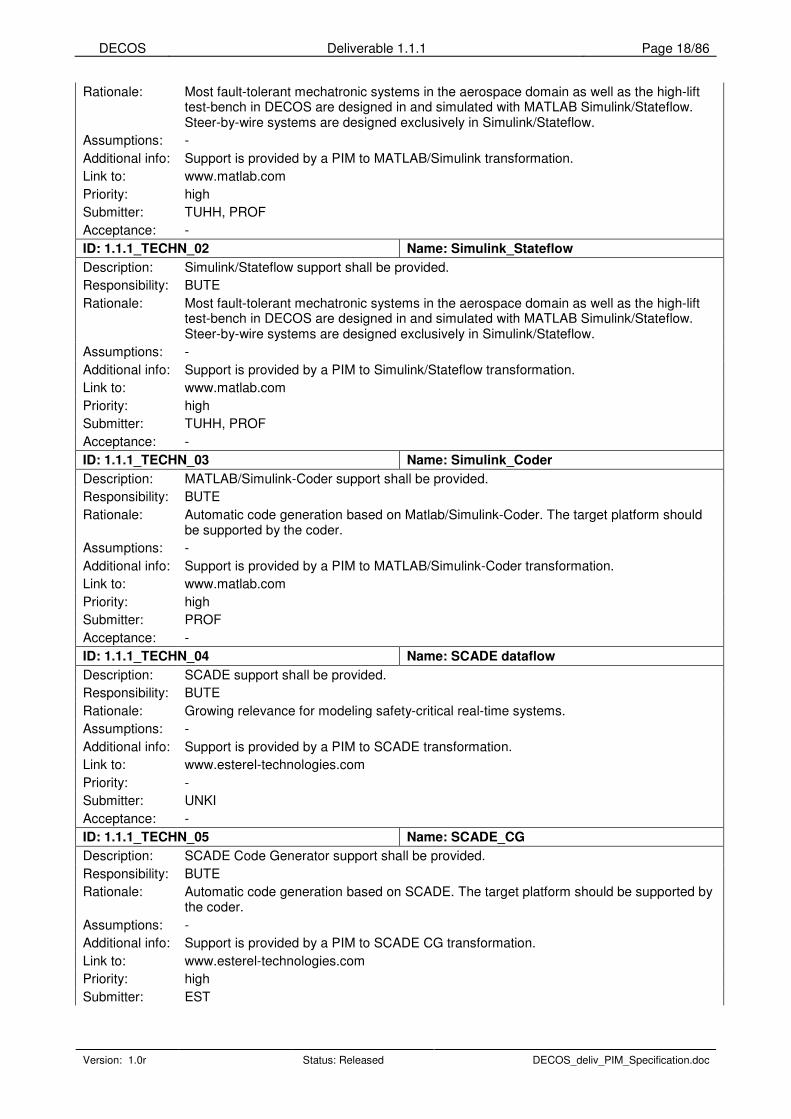
3.3.2.2 Technology and design methodology requirements
The following table lists the technologies and design methodologies PIM shall / should support in order to be able to use it in the everyday work of project partners. The transformation will transform the PIM to the input model of these supported technologies and methodologies.
ID: 1.1.1_TECHN_01 Name: MATLAB_Simulink
Description: MATLAB/Simulink support shall be provided.
Responsibility: BUTE
DECOS Deliverable 1.1.1 Page 18/86
Version: 1.0r Status: Released DECOS_deliv_PIM_Specification.doc
Rationale: Most fault-tolerant mechatronic systems in the aerospace domain as well as the high-lift test-bench in DECOS are designed in and simulated with MATLAB Simulink/Stateflow. Steer-by-wire systems are designed exclusively in Simulink/Stateflow.
Assumptions: -
Additional info: Support is provided by a PIM to MATLAB/Simulink transformation.
Link to: www.matlab.com
Priority: high
Submitter: TUHH, PROF
Acceptance: -
ID: 1.1.1_TECHN_02 Name: Simulink_Stateflow
Description: Simulink/Stateflow support shall be provided.
Responsibility: BUTE
Rationale: Most fault-tolerant mechatronic systems in the aerospace domain as well as the high-lift test-bench in DECOS are designed in and simulated with MATLAB Simulink/Stateflow. Steer-by-wire systems are designed exclusively in Simulink/Stateflow.
Assumptions: -
Additional info: Support is provided by a PIM to Simulink/Stateflow transformation.
Link to: www.matlab.com
Priority: high
Submitter: TUHH, PROF
Acceptance: -
ID: 1.1.1_TECHN_03 Name: Simulink_Coder
Description: MATLAB/Simulink-Coder support shall be provided.
Responsibility: BUTE
Rationale: Automatic code generation based on Matlab/Simulink-Coder. The target platform should be supported by the coder.
Assumptions: -
Additional info: Support is provided by a PIM to MATLAB/Simulink-Coder transformation.
Link to: www.matlab.com
Priority: high
Submitter: PROF
Acceptance: -
ID: 1.1.1_TECHN_04 Name: SCADE dataflow
Description: SCADE support shall be provided.
Responsibility: BUTE
Rationale: Growing relevance for modeling safety-critical real-time systems.
Assumptions: -
Additional info: Support is provided by a PIM to SCADE transformation.
Link to: www.esterel-technologies.com
Priority: -
Submitter: UNKI
Acceptance: -
ID: 1.1.1_TECHN_05 Name: SCADE_CG
Description: SCADE Code Generator support shall be provided.
Responsibility: BUTE
Rationale: Automatic code generation based on SCADE. The target platform should be supported by the coder.
Assumptions: -
Additional info: Support is provided by a PIM to SCADE CG transformation.
Link to: www.esterel-technologies.com
Priority: high
Submitter: EST
DECOS Deliverable 1.1.1 Page 19/86
Version: 1.0r Status: Released DECOS_deliv_PIM_Specification.doc
Acceptance: -
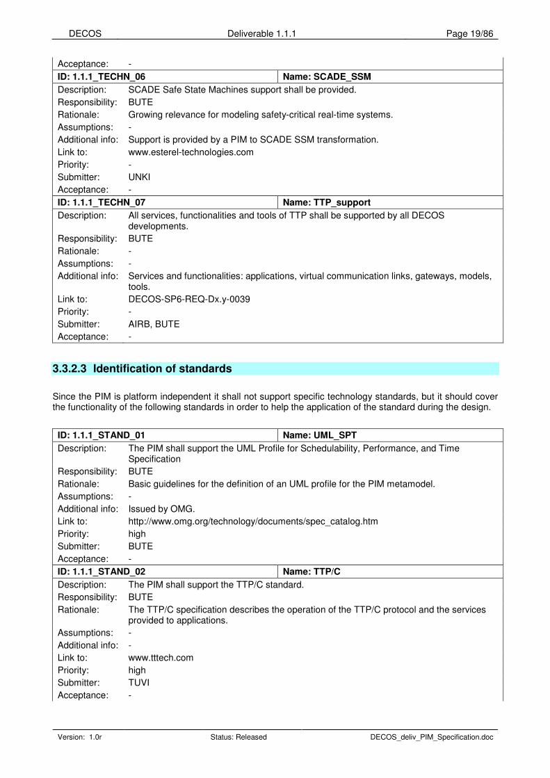
ID: 1.1.1_TECHN_06 Name: SCADE_SSM
Description: SCADE Safe State Machines support shall be provided.
Responsibility: BUTE
Rationale: Growing relevance for modeling safety-critical real-time systems.
Assumptions: -
Additional info: Support is provided by a PIM to SCADE SSM transformation.
Link to: www.esterel-technologies.com
Priority: -
Submitter: UNKI
Acceptance: -
ID: 1.1.1_TECHN_07 Name: TTP_support
Description: All services, functionalities and tools of TTP shall be supported by all DECOS developments.
Responsibility: BUTE
Rationale: -
Assumptions: -
Additional info: Services and functionalities: applications, virtual communication links, gateways, models, tools.
Link to: DECOS-SP6-REQ-Dx.y-0039
Priority: -
Submitter: AIRB, BUTE
Acceptance: -
3.3.2.3 Identification of standards
Since the PIM is platform independent it shall not support specific technology standards, but it should cover the functionality of the following standards in order to help the application of the standard during the design.
ID: 1.1.1_STAND_01 Name: UML_SPT
Description: The PIM shall support the UML Profile for Schedulability, Performance, and Time Specification
Responsibility: BUTE
Rationale: Basic guidelines for the definition of an UML profile for the PIM metamodel.
Assumptions: -
Additional info: Issued by OMG.
Link to: http://www.omg.org/technology/documents/spec_catalog.htm
Priority: high
Submitter: BUTE
Acceptance: -
ID: 1.1.1_STAND_02 Name: TTP/C
Description: The PIM shall support the TTP/C standard.
Responsibility: BUTE
Rationale: The TTP/C specification describes the operation of the TTP/C protocol and the services provided to applications.
Assumptions: -
Additional info: -
Link to: www.tttech.com
Priority: high
Submitter: TUVI
Acceptance: -

DECOS Deliverable 1.1.1 Page 20/86
Version: 1.0r Status: Released DECOS_deliv_PIM_Specification.doc
ID: 1.1.1_STAND_03 Name: CAN
Description: The PIM shall support the CAN Specification Version 2.0.
Responsibility: BUTE
Rationale: Specification of the CAN serial communication protocol.
Assumptions: -
Additional info: -
Link to: http://www.can.bosch.com/content/Literature.html
Priority: high
Submitter: TUVI
Acceptance: -
ID: 1.1.1_STAND_04 Name: LIN
Description: The PIM shall support the LIN Specification Package Revision 1.3.
Responsibility: BUTE
Rationale: The LIN specification includes the LIN protocol, a uniform format for the description of an entire LIN network and the interface between a LIN network and the application.
Assumptions: -
Additional info: -
Link to: www.lin-subbus.org
Priority: high
Submitter: TUVI
Acceptance: -
ID: 1.1.1_STAND_05 Name: Profibus
Description: The PIM shall support the Profibus standard.
Responsibility: BUTE
Rationale: PROFIBUS is an open, communication system with a wide range of applications, particularly in the fields of factory and process automation.
Assumptions: -
Additional info: -
Link to: www.profibus.com
Priority: high
Submitter: PROF
Acceptance: -
ID: 1.1.1_STAND_06 Name: FlexRay
Description: FlexRey support shall be provided.
Responsibility: BUTE
Rationale: -
Assumptions: -
Additional info: -
Link to: www.flexray.com
Priority: -
Submitter: AUDI
Acceptance: -
ID: 1.1.1_STAND_07 Name: internet_protocol
Description: The PIM shall support Internet Protocols (e.g., TCP/IP, UDP).
Responsibility: BUTE
Rationale: RFC 768, RFC 791, RFC 793 - Internet Protocol Standards.
Assumptions: -
Additional info: -
Link to: http://www.rfc-archive.org
Priority: high
Submitter: TUVI
Acceptance: -

DECOS Deliverable 1.1.1 Page 21/86
Version: 1.0r Status: Released DECOS_deliv_PIM_Specification.doc
ID: 1.1.1_STAND_08 Name: DO178B
Description: DO178B support shall be provided.
Responsibility: BUTE
Rationale: -
Assumptions: -
Additional info: -
Link to: -
Priority: -
Submitter: TTT
Acceptance: -
ID: 1.1.1_STAND_09 Name: compliance
Description: To satisfy all validation & verification, safety, certification and legal requirements all tools, applications, software and hardware developed in DECOS subprojects shall show compliance to the following documents.
Responsibility: BUTE
Rationale: -
Assumptions: The requirement model (i.e. PIM) should not satisfy these standards. These will be satisfied by the engineering model that is generated from the PIM. From the PIM by a transformation a human readable format of the requirements can be extracted that complies these standards.
Additional info: SAE ARP 4754 “Certification Considerations For Highly Integrated Or Complex Aircraft Systems”; SAE ARP 4761 “Guidelines & Methods for Conducting the Safety Assessment Process on Civil Airborne Systems and Equipment"; SAE ARP 5580 “Recommended Failure Modes and Effects Analysis (FMEA) Practices for Non-Automobile Applications”; RTCA/DO-178B “Software Considerations in Airborne Systems and Equipment Certification”; RTCA/DO-254 “Design Assurance Guidance for Airborne Electronic Hardware“; RTCA/DO-160 “DO-160A, Environmental Conditions and Test Procedures for Airborne Equipment”; AC 25.1309 “System Design and Analysis, Advisory Circular”, FAA; AMJ 25.1309 “System Design and Analysis, Advisory Material Joint”, JAA
Link to: DECOS-SP6-REQ-Dx.y-0023
Priority: -
Submitter: AIRB
Acceptance: -
3.3.3 Functional requirements
3.3.3.1 DAS related requirements
The system consists of DASs that can interact and cooperate.
ID: 1.1.1_FUNC_DAS_01 Name: das
Description: The PIM shall represent DASs.
Responsibility: BUTE
Rationale: -
Assumptions: -
Additional info: -
Link to: -
Priority: high
Submitter: BUTE
Acceptance: -

DECOS Deliverable 1.1.1 Page 22/86
Version: 1.0r Status: Released DECOS_deliv_PIM_Specification.doc
ID: 1.1.1_FUNC_DAS_02 Name: das_type
Description: The PIM shall represent DAS types.
Responsibility: BUTE
Rationale: -
Assumptions: DAS types are: safety-critical, non-safety-critical, time-triggered, event-triggered, Profibus, distributed control, TTA
Additional info: If partners express their need the general PIM metamodel can be specialized in a later phase of the project to describe a given type of DAS by removing the modeling elements belonging to other DAS types.
Link to: -
Priority: high
Submitter: TUVI, PROF, TTT
Acceptance: -
ID: 1.1.1_FUNC_DAS_03 Name: das_interface
Description: The PIM shall represent the interface of DASs to the environment and to each other.
Responsibility: BUTE
Rationale: Interface to relevant signals of the environment. The elements and messages that are imported / exported via an inter-DAS gateway.
Assumptions: -
Additional info: -
Link to: -
Priority: high
Submitter: PROF, BUTE
Acceptance: -
ID: 1.1.1_FUNC_DAS_04 Name: das_operating_mode
Description: The PIM shall represent operating modes of DASs.
Responsibility: BUTE
Rationale: -
Assumptions: Some examples of these operating modes are: normal operation, startup, flashing, maintenance, degraded.
Additional info: -
Link to: -
Priority: high
Submitter: BUTE
Acceptance: -
ID: 1.1.1_FUNC_DAS_05 Name: das_initial_operating_mode
Description: The PIM shall represent the initial operating mode of DASs.
Responsibility: BUTE
Rationale: -
Assumptions: -
Additional info: -
Link to: -
Priority: high
Submitter: BUTE
Acceptance: -
ID: 1.1.1_FUNC_DAS_06 Name: das_operating_mode_change
Description: The PIM shall represent operating mode changes of DASs.
Responsibility: BUTE
Rationale: -
Assumptions: -
Additional info: -
Link to: -

DECOS Deliverable 1.1.1 Page 23/86
Version: 1.0r Status: Released DECOS_deliv_PIM_Specification.doc
Priority: high
Submitter: BUTE
Acceptance: -
3.3.3.2 Job related requirements
DASs are composed of communicating jobs.
ID: 1.1.1_FUNC_JOB_01 Name: job
Description: The PIM shall represent jobs.
Responsibility: BUTE
Rationale: -
Assumptions: -
Additional info: -
Link to: -
Priority: high
Submitter: BUTE, TUVI, TTT
Acceptance: -
ID: 1.1.1_FUNC_JOB_02 Name: job_interface
Description: The PIM shall represent the interface of jobs.
Responsibility: BUTE
Rationale: This is the base of component integration. Components that are not part of the DAS will be described in the PIM as external services.
Assumptions: -
Additional info: This attribute can be used to describe the application programming interface expected by the job (e.g. Interface File System, LIN API).
Link to: -
Priority: high
Submitter: TUVI, BUTE
Acceptance: -
ID: 1.1.1_FUNC_JOB_03 Name: job_produce/publish_property
Description: The PIM shall represent the produce/publish property of jobs.
Responsibility: BUTE
Rationale: The messages and data streams produced by the job.
Assumptions: -
Additional info: -
Link to: -
Priority: high
Submitter: TUVI
Acceptance: -
ID: 1.1.1_FUNC_JOB_04 Name: job_consumer/subscriber_property
Description: The PIM shall represent the consumer/subscribe property of jobs.
Responsibility: BUTE
Rationale: The messages and data streams consumed by the job.
Assumptions: -
Additional info: -
Link to: -
Priority: high
Submitter: TUVI
Acceptance: -

DECOS Deliverable 1.1.1 Page 24/86
Version: 1.0r Status: Released DECOS_deliv_PIM_Specification.doc
3.3.3.3 Message related requirements
ID: 1.1.1_FUNC_MESS_01 Name: message
Description: The PIM shall represent messages.
Responsibility: BUTE
Rationale: -
Assumptions: -
Additional info: -
Link to: -
Priority: high
Submitter: BUTE, TUVI, TTT
Acceptance: -
ID: 1.1.1_FUNC_MESS_02 Name: message_elements
Description: Messages shall consist of primitive elements.
Responsibility: BUTE
Rationale: -
Assumptions: -
Additional info: -
Link to: -
Priority: high
Submitter: BUTE, TUVI
Acceptance: -
ID: 1.1.1_FUNC_MESS_03 Name: message_producer
Description: The PIM shall represent the producers of a specific message.
Responsibility: BUTE
Rationale: -
Assumptions: -
Additional info: -
Link to: -
Priority: high
Submitter: BUTE, TUVI, TTT
Acceptance: -
ID: 1.1.1_FUNC_MESS_04 Name: message_consumer
Description: The PIM shall represent the consumers of a specific message.
Responsibility: BUTE
Rationale: -
Assumptions: -
Additional info: -
Link to: -
Priority: high
Submitter: BUTE, TUVI, TTT
Acceptance: -
ID: 1.1.1_FUNC_MESS_05 Name: message_transmission_type
Description: The PIM shall represent message transmission types.
Responsibility: BUTE
Rationale: -
Assumptions: Transmission types are: unicast, multicast, broadcast.
Additional info: -

DECOS Deliverable 1.1.1 Page 25/86
Version: 1.0r Status: Released DECOS_deliv_PIM_Specification.doc
Link to: DECOS-SP6-REQ-Dx.y-0004, DECOS-SP6-REQ-Dx.y-0005, DECOS-SP6-REQ-Dx.y-0006
Priority: high
Submitter: BUTE, AIRB
Acceptance: -
ID: 1.1.1_FUNC_MESS_06 Name: message_validity_span
Description: The PIM shall represent the validity span of a specific message.
Responsibility: BUTE
Rationale: Length of time the message remains valid. A data is valid if the time between the reception of this data and the time the application / partition reads this data is lower than a parameter associated to the port and defined as the maximum age of the data.
Assumptions: -
Additional info: -
Link to: DECOS-SP6-REQ-Dx.y-0009
Priority: high
Submitter: AIRB, TUVI, TTT
Acceptance: -
ID: 1.1.1_FUNC_MESS_07 Name: message_RDA
Description: The PIM shall represent the properties of a message that are needed to decide the Replica Determinism Algorithm if needed.
Responsibility: BUTE
Rationale: E.g. can it be averaged or not. One should decide the algorithm here, just give hints to the transformation to choose the most appropriate one.
Assumptions: -
Additional info: -
Link to: -
Priority: high
Submitter: BUTE, TTT
Acceptance: -
ID: 1.1.1_FUNC_MESS_08 Name: message_types
Description: Messages shall have types.
Responsibility: BUTE
Rationale: -
Assumptions: Message types are: job-job, sensor-job, job-actuator, interrupt.
Additional info: -
Link to: -
Priority: high
Submitter: BUTE
Acceptance: -
ID: 1.1.1_FUNC_MESS_09 Name: message_job-job
Description: Job-job messages shall have subtypes.
Responsibility: BUTE
Rationale: -
Assumptions: Job-job messages subtypes are: state message, event message.
Additional info: -
Link to: -
Priority: high
Submitter: BUTE
Acceptance: -
ID: 1.1.1_FUNC_MESS_10 Name: message_dependency
Description: The PIM shall represent a “depends” relation amongst messages.
Responsibility: BUTE

DECOS Deliverable 1.1.1 Page 26/86
Version: 1.0r Status: Released DECOS_deliv_PIM_Specification.doc
Rationale: Sequence constraints for messages. This is required for functional design.
Assumptions: -
Additional info: -
Link to: -
Priority: high
Submitter: TTT
Acceptance: -
ID: 1.1.1_FUNC_MESS_11 Name: inter-system_communication
Description: The Communication Bus System shall support all types of inter-system communication including periodic and aperiodic data transfer.
Responsibility: BUTE
Rationale: -
Assumptions: -
Additional info: -
Link to: DECOS-SP6-REQ-Dx.y-0003
Priority: -
Submitter: AIRB
Acceptance: -
ID: 1.1.1_FUNC_MESS_12 Name: message_transmission_mechanism
Description: The PIM shall represent the transmission mechanism of messages.
Responsibility: BUTE
Rationale: Control flow in relation to data flow for message transmission (information push or information pull mechanism).
Assumptions: Transmission mechanisms are: push, pull.
Additional info: -
Link to: -
Priority: high
Submitter: TUVI
Acceptance: -
ID: 1.1.1_FUNC_MESS_13 Name: message_reception_mechanism
Description: The PIM shall represent the reception mechanism of messages.
Responsibility: BUTE
Rationale: Control flow in relation to data flow for message transmission (information push or information pull mechanism).
Assumptions: Reception mechanisms are: push, pull.
Additional info: -
Link to: -
Priority: high
Submitter: TUVI
Acceptance: -
ID: 1.1.1_FUNC_MESS_14 Name: message_sender_status
Description: The PIM shall represent the sender status of messages.
Responsibility: BUTE
Rationale: Specifies if a sender-status information is transmitted along with the message. A sender-status allows the sending host to tell the receivers of the message that the message value is not valid (low quality).
Assumptions: -
Additional info: -
Link to: -
Priority: high
Submitter: TTT
Acceptance: -

DECOS Deliverable 1.1.1 Page 27/86
Version: 1.0r Status: Released DECOS_deliv_PIM_Specification.doc
ID: 1.1.1_FUNC_MESS_15 Name: message_phase_shift
Description: The PIM shall represent the phase shift of messages.
Responsibility: BUTE
Rationale: Phase shift relationship to construct phase-aligned transactions.
Assumptions: -
Additional info: -
Link to: -
Priority: high
Submitter: TUVI
Acceptance: -
3.3.3.4 Element related requirements
ID: 1.1.1_FUNC_ELEM_01 Name: element
Description: The PIM shall represent primitive elements.
Responsibility: BUTE
Rationale: Messages are built of these primitive elements.
Assumptions: -
Additional info: -
Link to: -
Priority: high
Submitter: BUTE, TUVI, TTT
Acceptance: -
ID: 1.1.1_FUNC_ELEM_02 Name: element_type
Description: The PIM shall represent the type / syntax of a primitive element.
Responsibility: BUTE
Rationale: The syntactic description of an element denotes the structure of the element as a combination of predefined data types (e.g. octet, integer, float, string) and other elements.
Assumptions: -
Additional info: -
Link to: -
Priority: high
Submitter: BUTE, TUVI
Acceptance: -
ID: 1.1.1_FUNC_ELEM_03 Name: element_size_type
Description: The PIM shall represent the size type of a primitive element.
Responsibility: BUTE
Rationale: The size of the element is either fixed or variable.
Assumptions: Size type is: fixed, variable.
Additional info: -
Link to: -
Priority: high
Submitter: TUVI
Acceptance: -
ID: 1.1.1_FUNC_ELEM_04 Name: element_length
Description: The PIM shall represent the length / size of a primitive element.
Responsibility: BUTE
Rationale: Only relevant for fixed length messages.
Assumptions: -
Additional info: -

DECOS Deliverable 1.1.1 Page 28/86
Version: 1.0r Status: Released DECOS_deliv_PIM_Specification.doc
Link to: -
Priority: high
Submitter: BUTE, TUVI, TTT
Acceptance: -
ID: 1.1.1_FUNC_ELEM_05 Name: element_initial_value
Description: The PIM shall represent the initial value of a primitive element.
Responsibility: BUTE
Rationale: -
Assumptions: -
Additional info: -
Link to: -
Priority: high
Submitter: BUTE, TUVI
Acceptance: -
3.3.3.5 Node and resource related requirements
ID: 1.1.1_FUNC_NODE_01 Name: resource
Description: The PIM shall represent resources.
Responsibility: BUTE
Rationale: Resource is an abstract device. Resource description is needed to be able to map jobs to nodes that have a specific device that is needed by a job. A job using a sensor or actuator can be found by locating the jobs that send / receive messages to / from a sensor / actuator.
Assumptions: -
Additional info: -
Link to: -
Priority: high
Submitter: BUTE
Acceptance: -
3.3.3.6 Data stream requirements
ID: 1.1.1_FUNC_STREAM_01 Name: data_stream
Description: The PIM shall describe data streams.
Responsibility: BUTE
Rationale: Data stream is the specialization of message.
Assumptions: -
Additional info: -
Link to: -
Priority: high
Submitter: BUTE, TUVI
Acceptance: -
3.3.4 Performance requirements
3.3.4.1 DAS performance requirements

DECOS Deliverable 1.1.1 Page 29/86
Version: 1.0r Status: Released DECOS_deliv_PIM_Specification.doc
ID: 1.1.1_PERF_DAS_01 Name: das_operating_mode
Description: The PIM shall represent operating mode performance requirements of DASs.
Responsibility: BUTE
Rationale: -
Assumptions: -
Additional info: -
Link to: -
Priority: high
Submitter: BUTE
Acceptance: -
3.3.4.2 Job performance requirements
ID: 1.1.1_PERF_JOB_01 Name: job_schedulability
Description: The PIM shall represent properties of jobs that are needed for schedulability analysis.
Responsibility: BUTE
Rationale: -
Assumptions: -
Additional info: -
Link to: -
Priority: high
Submitter: BUTE
Acceptance: -
ID: 1.1.1_PERF_JOB_02 Name: job_period
Description: The PIM shall represent the period of jobs.
Responsibility: BUTE
Rationale: Execution period of the job.
Assumptions: -
Additional info: -
Link to: -
Priority: high
Submitter: TUVI
Acceptance: -
ID: 1.1.1_PERF_JOB_03 Name: job_phase
Description: The PIM shall represent the phase of jobs.
Responsibility: BUTE
Rationale: Phase shift relationship to construct phase-aligned transactions.
Assumptions: -
Additional info: -
Link to: -
Priority: high
Submitter: TUVI
Acceptance: -
ID: 1.1.1_PERF_JOB_04 Name: job_outgoing_bandwidth
Description: The PIM shall represent the outgoing bandwidth of jobs.
Responsibility: BUTE
Rationale: Bandwidth required to ensure extensibility for additional messages and data streams.
Assumptions: -
Additional info: -

DECOS Deliverable 1.1.1 Page 30/86
Version: 1.0r Status: Released DECOS_deliv_PIM_Specification.doc
Link to: -
Priority: high
Submitter: TUVI
Acceptance: -
ID: 1.1.1_PERF_JOB_05 Name: job_incoming_buffering
Description: The PIM shall represent buffering capacity for incoming messages of jobs.
Responsibility: BUTE
Rationale: The size of the incoming message queues.
Assumptions: -
Additional info: -
Link to: -
Priority: high
Submitter: TUVI
Acceptance: -
ID: 1.1.1_PERF_JOB_06 Name: job_outgoing_buffering
Description: The PIM shall represent buffering capacity for outgoing messages of jobs.
Responsibility: BUTE
Rationale: The size of the outgoing message queues.
Assumptions: -
Additional info: -
Link to: -
Priority: high
Submitter: TUVI
Acceptance: -
3.3.4.3 Message performance requirements
ID: 1.1.1_PERF_MESS_01 Name: message_schedulability
Description: The PIM shall represent properties of messages that are needed for schedulability analysis.
Responsibility: BUTE
Rationale: -
Assumptions: -
Additional info: -
Link to: -
Priority: high
Submitter: BUTE, TUVI, TTT
Acceptance: -
ID: 1.1.1_PERF_MESS_02 Name: message_period
Description: The PIM shall represent the period of messages.
Responsibility: BUTE
Rationale: Transmission period of the message.
Assumptions: -
Additional info: -
Link to: -
Priority: high
Submitter: TUVI
Acceptance: -
ID: 1.1.1_PERF_MESS_03 Name: message_interarrival_time
Description: The PIM shall represent the interarrival time of messages.
DECOS Deliverable 1.1.1 Page 31/86
Version: 1.0r Status: Released DECOS_deliv_PIM_Specification.doc
Responsibility: BUTE
Rationale: Minimum time between transmissions of the message.
Assumptions: -
Additional info: -
Link to: -
Priority: high
Submitter: TUVI
Acceptance: -
ID: 1.1.1_PERF_MESS_04 Name: message_service_time
Description: The PIM shall represent the service time of messages.
Responsibility: BUTE
Rationale: Maximum time between fetch operations for the message.
Assumptions: -
Additional info: -
Link to: -
Priority: high
Submitter: TUVI
Acceptance: -
ID: 1.1.1_PERF_MESS_05 Name: message_latency_time
Description: The PIM shall represent the latency of messages.
Responsibility: BUTE
Rationale: Maximum permitted time between transmission and reception of the message.
Assumptions: -
Additional info: -
Link to: DECOS-SP6-REQ-Dx.y-0007
Priority: high
Submitter: TUVI, AIRB
Acceptance: -
3.3.4.4 Data stream performance requirements
ID: 1.1.1_PERF_STREAM_01 Name: data_stream_bandwidth
Description: The PIM shall represent the bandwidth requirement of a data stream.
Responsibility: BUTE
Rationale: -
Assumptions: -
Additional info: Bandwidth means effective bandwidth, that is, protocol overhead and other platform specific overheads are not included.
Link to: -
Priority: high
Submitter: BUTE, TUVI
Acceptance: -
ID: 1.1.1_PERF_STREAM_02 Name: data_stream_jitter
Description: The PIM shall represent the jitter requirement of a data stream.
Responsibility: BUTE
Rationale: Needed to determine buffer sizes.
Assumptions: -
Additional info: -
Link to: -
Priority: high

DECOS Deliverable 1.1.1 Page 32/86
Version: 1.0r Status: Released DECOS_deliv_PIM_Specification.doc
Submitter: BUTE
Acceptance: -
ID: 1.1.1_PERF_STREAM_03 Name: data_stream_latency
Description: The PIM shall represent the latency requirement of a data stream.
Responsibility: BUTE
Rationale: -
Assumptions: -
Additional info: -
Link to: -
Priority: high
Submitter: BUTE
Acceptance: -
3.3.5 Dependability requirements
3.3.5.1 DAS dependability requirements
ID: 1.1.1_DEP_DAS_01 Name: das_operating_mode
Description: The PIM shall represent the operating mode dependability requirements of DASs.
Responsibility: BUTE
Rationale: -
Assumptions: -
Additional info: -
Link to: -
Priority: high
Submitter: BUTE
Acceptance: -
ID: 1.1.1_DEP_DAS_02 Name: das_sil
Description: The PIM shall represent the Safety Integrity Level (SIL) of DASs.
Responsibility: BUTE
Rationale: A classification number which determines the techniques and measures that have to be applied in order to reduce residual software faults to an appropriate level.
Assumptions: -
Additional info: -
Link to: -
Priority: high
Submitter: BUTE, TUVI
Acceptance: -
ID: 1.1.1_DEP_DAS_03 Name: dual_redundancy
Description: All system functions shall be implemented with at least dual redundancy, except if the aircraft can be dispatched following loss of the function, without any time limitation and without any operational consequence.
Responsibility: BUTE
Rationale: -
Assumptions: The application will be developed for aircraft.
Additional info: -
Link to: DECOS-SP6-REQ-Dx.y-0017
Priority: -
Submitter: AIRB

DECOS Deliverable 1.1.1 Page 33/86
Version: 1.0r Status: Released DECOS_deliv_PIM_Specification.doc
Acceptance: -
ID: 1.1.1_DEP_DAS_04 Name: das_failure_mode
Description: The PIM shall represent the failure mode of DASs.
Responsibility: BUTE
Rationale: -
Assumptions: Failure modes are: fail-silent, fail-safe, etc.
Additional info: -
Link to: -
Priority: high
Submitter: BUTE
Acceptance: -
3.3.5.2 Job dependability requirements
ID: 1.1.1_DEP_JOB_01 Name: job_failure_mode
Description: The PIM shall represent the failure mode of a job.
Responsibility: BUTE
Rationale: -
Assumptions: Failure modes are: fail-silent, fail-safe, etc.
Additional info: -
Link to: -
Priority: high
Submitter: BUTE
Acceptance: -
3.3.5.3 Message dependability requirements
ID: 1.1.1_DEP_MESS_01 Name: message_idempotency
Description: The PIM shall represent whether a message is idempotent.
Responsibility: BUTE
Rationale: -
Assumptions: -
Additional info: -
Link to: -
Priority: high
Submitter: BUTE
Acceptance: -
ID: 1.1.1_DEP_MESS_02 Name: message_redundancy
Description: The PIM shall represent the redundancy degree of messages.
Responsibility: BUTE
Rationale: Number of channels for transmission of this message.
Assumptions: -
Additional info: -
Link to: -
Priority: high
Submitter: TTT
Acceptance: -

DECOS Deliverable 1.1.1 Page 34/86
Version: 1.0r Status: Released DECOS_deliv_PIM_Specification.doc
3.3.5.4 Data stream dependability requirements
ID: 1.1.1_DEP_STREAM_01 Name: data_stream_error_rate
Description: The PIM shall represent the error rate requirement of a data stream.
Responsibility: BUTE
Rationale: -
Assumptions: -
Additional info: -
Link to: -
Priority: high
Submitter: BUTE
Acceptance: -
3.3.6 Diagnostic Requirements
The integrated diagnostic services of the DECOS integrated architecture support both application and system specific diagnosis. While system specific diagnosis focuses on the detection of internal and external hardware faults, the discrimination between hardware and software faults, and the detection of precursors for pending hardware problems (i.e. condition based maintenance), the task of the application diagnosis as part of the PIM is to reveal application-specific hardware and software faults.
ID: 1.1.1_DEP_DIAG_01 Name: symptom_name
Description: The symptom name should uniquely identify the symptom.
Responsibility: BUTE, TUVI
Rationale: The domain element symptom has an attribute called name that has the type text.
Assumptions: -
Additional info: -
Link to: -
Priority: high
Submitter: TUVI
Acceptance: -
ID: 1.1.1_DEP_DIAG_02 Name: symptom_expression
Description: The symptom expression should define the relationship in time, space, and value of interface state variables.
Responsibility: BUTE, TUVI
Rationale: The domain element symptom has an attribute called expression that has the type of text.
Assumptions: -
Additional info: -
Link to: -
Priority: High
Submitter: TUVI
Acceptance: -
ID: 1.1.1_DEP_DIAG_03 Name: ONA_name
Description: The Out-of-Norm Assertion (ONA) name should uniquely identify the ONA.
Responsibility: BUTE, TUVI
Rationale: The domain element ONA has an attribute called name that has the type of text.
Assumptions: -
Additional info: -
Link to: -
Priority: high
Submitter: TUVI

DECOS Deliverable 1.1.1 Page 35/86
Version: 1.0r Status: Released DECOS_deliv_PIM_Specification.doc
Acceptance: -
ID: 1.1.1_DEP_DIAG_04 Name: ONA_expression
Description: The ONA expression defines the relationship in time, space, and value of symptoms.
Responsibility: BUTE, TUVI
Rationale: The domain element ONA has an attribute called expression that has the type of text.
Assumptions: -
Additional info: -
Link to: -
Priority: high
Submitter: TUVI
Acceptance: -
ID: 1.1.1_DEP_DIAG_05 Name: job_diagnostic_output
Description: The diagnostic output of the job is optional diagnostic information, provided in addition to the diagnostic information gathered at the architecture level.
Responsibility: BUTE, TUVI
Rationale: The domain element job has an attribute called diagnostic output that has the type of message.
Assumptions: -
Additional info: -
Link to: -
Priority: high
Submitter: TUVI
Acceptance: -

DECOS Deliverable 1.1.1 Page 36/86
Version: 1.0r Status: Released DECOS_deliv_PIM_Specification.doc
4 Relation to modeling standards
Modeling technology standards are important in order to provide widely accepted up-to-date modeling and model based development technology for the user. The accordance with these standards is a key element to the portability, interchangeability and reusability of the model.
4.1 MOF
The Meta-Object Facility (MOF) is a standard of the Object Management Group (OMG) - www.omg.org/mof. The MOF specification defines an abstract language and a framework for specifying, constructing, and managing technology neutral metamodels. Since the proposed DECOS PIM and PIM metamodel should be technology independent, MOF seems to be a natural mean to describe DECOS applications. A metamodel is in effect an abstract language for some kind of metadata. Examples include the metamodels for UML, CWM, SysML and the MOF itself.
The specification of MOF includes the following DECOS relevant aspects:
♦ a formal definition of the MOF meta-metamodel; that is, the abstract language for specifying MOF metamodels,
♦ an XMI format for MOF metamodel interchange.
The XML Metadata Interchange (XMI) specification defines technology mappings from MOF metamodels to XML DTDs (Document Type Definition) and XML documents. These mappings can be used to define an interchange format for metadata conforming to a given MOF metamodel (see more in the section about XML).
UML and MOF are normally viewed in the context of a conceptual layered metadata architecture. Although the metamodels for MOF and UML are designed to be architecturally aligned, sharing a common subset of core object modeling constructs, this does not bind the modeler to stick to UML as the modeling language. Just on the contrary, the whole metamodeling mechanism is useful to provide a common modeling framework where model instantiation can occur using different modeling languages.
The classical framework for metamodeling is based on an architecture with four metalayers. These layers are conventionally described as follows:
1. the information layer with the data that should be described;
2. the model layer with an abstract representation of the data in the information layer;
3. the metamodel layer with the descriptions that define the structure and semantics of metadata;
4. the meta-metamodel layer with the description of the structure and semantics of meta-metadata.
Figure 4 describes this classical four layer framework.

DECOS Deliverable 1.1.1 Page 37/86
Version: 1.0r Status: Released DECOS_deliv_PIM_Specification.doc
Figure 4: MOF 4-layer framework (source: MOF Specification by OMG [MOF 2002])
As the first adopted technologies specified using a metamodeling approach, the UML, MOF, and XMI provide the foundation for OMG's Metamodel Driven Architecture (MDA) - see the section about MDA. Future metamodel standards should reuse MOF and UML’s core semantics and emulate their systematic approach to architecture alignment.
The PIM metamodel by its construction corresponds to the third layer of the 4-layer MOF metamodeling framework. As the MOF metamodel has a strong correlation with UML so has the DECOS PIM metamodel too. Please note again, that this strong correlation does not automatically impose that the modeling language, i.e. the concrete syntax and semantics of the language that is used to describe the model, of DECOS is UML. The result of work package WP1.1 in the DECOS project provides a PIM metamodel and additionally as a usage example of this metamodel of how to incorporate it into a given modeling language as extension, a UML profile for DECOS that extends UML by the aspects of the PIM metamodel.
4.2 MDA
The Model-Driven Architecture (MDA) is a specification of the Object Management Group (OMG) - www.omg.org/mda. MDA starts with the well-known and long established idea of separating the specification of the operation of a system from the details of the way that system uses the capabilities of its platform.
MDA provides an approach for and enables tools to be provided for:
♦ specifying a system independently of the platform that supports it,
♦ specifying platforms,
♦ choosing a particular platform for the system, and
♦ transforming the system specification into one for a particular platform.
The three primary goals of MDA are:
♦ portability,
♦ interoperability,
♦ reusability.
According to all of the above MDA suits very well to be the methodological base behind the suggested DECOS tool chain and product development life-cycle. The notions of PIM, PSM, and PIM to PSM transformation of the DECOS project proposal fit perfectly to the MDA approach.

DECOS Deliverable 1.1.1 Page 38/86
Version: 1.0r Status: Released DECOS_deliv_PIM_Specification.doc
The main concepts of MDA are (excerpts from the specification):
system - A system may include anything that exists or is planned to exist: a program, a single computer system, some combination of parts of different systems, a federation of systems, each under separate control, people, an enterprise, a federation of enterprises.
model - A model of a system is a description or specification of that system and its environment for some certain purpose. A model is often presented as a combination of drawings and text. The text may be in a modeling language or in a natural language.
application - An application is a functionality being developed. A system is described in terms of one or more applications supported by one or more platforms.
platform - A platform is a set of subsystems and technologies that provide a coherent set of functionality through interfaces and specified usage patterns, which any application supported by that platform can use without concern for the details of how the functionality provided by the platform is implemented.
platform independent model - A platform independent model is a view of a system from the platform independent viewpoint. A PIM exhibits a specified degree of platform independence so as to be suitable for use with a number of different platforms of similar type.
platform specific model - A platform specific model is a view of a system from the platform specific viewpoint. A PSM combines the specifications in the PIM with the details that specify how that system uses a particular type of platform.
platform model - A platform model provides a set of technical concepts, representing the different kinds of parts that make up a platform and the services provided by that platform. It also provides, for use in a platform specific model, concepts representing the different kinds of elements to be used in specifying the use of the platform by an application. A platform model also specifies requirements on the connection and use of the parts of the platform, and the connections of an application to the platform.
model transformation - Model transformation is the process of converting one model to another model of the same system.
implementation - An implementation is a specification, which provides all the information needed to construct a system and to put it into operation.
MDA is said to be model-driven because it provides a means for using models to direct the course of understanding, design, construction, deployment, operation, maintenance and modification. It suggests using different models at the different levels of abstraction and at different phases of development during system development. The process of development will consist of the composition and refinement of models. Transformations serve as means of progressive refinement of models from abstract, platform independent, requirement centric towards concrete, platform specific, implementation centric.
The DECOS model application workflow strongly resembles the suggestion of MDA. Therefore the usage of MDA (how the MDA models relate to each other and how they are used, how model transformation is done) is discussed in more details in the section of "Application workflow".
4.3 UML
The Unified Modeling Language (UML) is a standard of the Object Management Group (OMG) - www.omg.org/uml. UML is a visual language for specifying, constructing and documenting the artifacts of systems. It is a general-purpose modeling language that can be used with all major object and component

DECOS Deliverable 1.1.1 Page 39/86
Version: 1.0r Status: Released DECOS_deliv_PIM_Specification.doc
methods, and that can be applied to all application domains and implementation platforms. During the last few years UML has emerged as the software industry’s dominant modeling language. It is widely accepted among system designers, analysists and programmers. The UML specification is defined using a metamodeling approach that adapts formal specification techniques. While this approach lacks some of the rigor of a formal specification method, it offers the advantages of being more intuitive and pragmatic for most implementors and practitioners.
In the DECOS project UML was selected as the description format of the PIM metamodel due to its wide acceptance in the system designer community; natural correspondence to metamodeling, especially MOF; well elaborated extensibility and broad tool support. This way the PIM metamodel has a semi-formal description that can be combined with the power of Object Constraint Language (OCL) in order to define a more rigorous syntax.
Using this UML description, tool vendors can take the metamodel and implement it according to the input language of their modeling tool. One such implementation is done in the framework of DECOS workpackage 1.1 where as a descriptive example UML was chosen to be enriched by the notions of the PIM metamodel. The result is a profile called UML profile for DECOS. UML tools that can utilize the profiling mechanism can import this UML profile for DECOS. Modelers can use the extended tool to capture the requirements of DASs of DECOS.
4.4 XML/XMI
The Extensible Markup Language (XML) is a W3C recommendation - www.w3c.org/xml. XML is a subset / application profile of Standard Generalized Markup Language (SGML) [ISO 8879]. Its goal is to enable generic SGML to be served, received, and processed on the Web. XML has been designed for ease of implementation and for interoperability with both SGML and HTML. XML describes a class of data objects called XML documents and partially describes the behavior of computer programs which process them. By design, XML documents are conforming SGML documents.
XML documents are made up of storage units called entities, which contain either parsed or unparsed data. Parsed data is made up of characters, some of which form character data, and some of which form markup. Markup encodes a description of the document's storage layout and logical structure. XML provides a mechanism to impose constraints on the storage layout and logical structure.
The DECOS related properties of XML are:
♦ XML supports a wide variety of applications.
♦ XML documents are easy to create.
♦ XML documents are human-legible and reasonably clear.
♦ It is easy to write programs which process XML documents.
♦ The XML design can be prepared quickly.
♦ The design of XML is formal and concise.
The XML Metadata Interchange (XMI) is a standard of the Object Management Group (OMG) - www.omg.org/xmi. XMI is a widely used interchange format for sharing data object using XML. Sharing objects in XML is a comprehensive solution that builds on sharing data with XML. XMI is applicable to a wide variety of data objects: analysis, software, components, and databases.
XMI defines many of the important aspects involved in describing data objects in XML:
♦ The representation of data objects in terms of XML elements and attributes is the foundation.

DECOS Deliverable 1.1.1 Page 40/86
Version: 1.0r Status: Released DECOS_deliv_PIM_Specification.doc
♦ Since objects are typically interconnected, XMI includes standard mechanisms to link data objects within the same file or across files.
♦ Object identity allows data objects to be referenced from other data objects in terms of IDs and UUIDs.
♦ The versioning of data objects and their definitions is handled by the XMI model.
♦ Validation of XMI documents using DTDs and Schemas.
XMI is a model driven XML integration framework for defining, interchanging, manipulating and integrating XML data and objects. XMI-based standards are in use for integrating tools, repositories, applications and data warehouses. The XMI standard provides rules by which a schema can be generated for any valid XMI-transmissible MOF-based metamodel.
The primary role of XMI in DECOS modeling is the support of integration of different tools by allowing the interchange of PIM among the different tools of the tool chain or even between different tools of different providers.
Furthermore the validation of the produced XML file is part of the verification which proves that the model data conforms to a metamodel. Certainly such checking alone cannot assure that the transferred information satisfies all the semantic constraints of the metamodel - see the proposed role of OCL. However the constraints (i.e. rules formulated in OCL) necessary for the full semantic check can be encoded in the schema manually and thus transferred from one tool to the other.
DECOS Deliverable 1.1.1 Page 41/86
Version: 1.0r Status: Released DECOS_deliv_PIM_Specification.doc
5 PIM metamodel
5.1 General introduction of the metamodel
In order to achieve a technology-invariant system design of the final application, its DECOS architecture design starts with a Platform Independent Model (PIM) of each Distributed Application Subsystem (DAS). As part of this activity the core operational semantics of the desired system services is captured.
At the beginning, a specification model (metamodel) for PIM is developed, which permits not only to capture PIM in a uniform way, but also to support the transformation to Platform Specific Models (PSM) as well as both PIM and PSM verification.
The design and the PIM to the PSM mapping consist of three parallel parts:
♦ Functional design: The functional specifications in the PIM should be satisfied by proper function allocation, configuration of the communication network and set-up of the (encapsulated) execution environment.
♦ Performance related design: The performance specifications in the PIM should be satisfied by proper resource allocation, communication and task scheduling according to the resource attributes offered by the platform.
♦ Dependability related design: The dependability specifications in the PIM should be satisfied by proper fault-tolerance techniques (redundancy management) that are selected on the basis of the available dependability attributes and failure modes of the platform.
Accordingly the PIM metamodel is built of 3 interdependent packages: the functionality package, the dependability package and the performance package. They are described in detail in the following chapters.
5.2 Detailed description of the PIM metamodel
5.2.1 Explanation of model elements
If possible, we refer to the DECOS Technology Paper for definitions. This is the document that should serve as a common reference for definitions. Definitions are typeset in italic and where not noted differently are cited from the technology paper.
The metamodel consists of three packages, see Figure 5. The FUNCTIONALITY package contains the model elements that describe the purely functional part of the design. The other two packages depend on the functionality package, because they use some of its elements. The PERFORMANCE and DEPENDABILITY packages introduce elements that describe the performance and dependability related aspects of the elements, respectively.
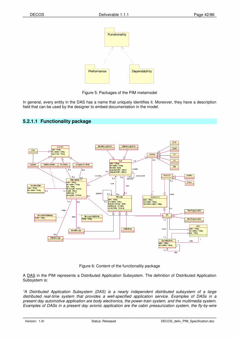
DECOS Deliverable 1.1.1 Page 42/86
Version: 1.0r Status: Released DECOS_deliv_PIM_Specification.doc
Functionality
Performance Dependability
Figure 5: Packages of the PIM metamodel
In general, every entity in the DAS has a name that uniquely identifies it. Moreover, they have a description field that can be used by the designer to embed documentation in the model.
5.2.1.1 Functionality package
Figure 6: Content of the functionality package
A DAS in the PIM represents a Distributed Application Subsystem. The definition of Distributed Application Subsystem is:
“A Distributed Application Subsystem (DAS) is a nearly independent distributed subsystem of a large distributed real-time system that provides a well-specified application service. Examples of DASs in a present day automotive application are body electronics, the power-train system, and the multimedia system. Examples of DASs in a present day avionic application are the cabin pressurization system, the fly-by-wire
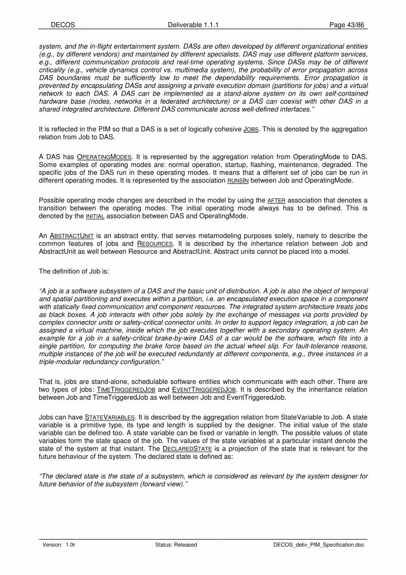
DECOS Deliverable 1.1.1 Page 43/86
Version: 1.0r Status: Released DECOS_deliv_PIM_Specification.doc
system, and the in-flight entertainment system. DASs are often developed by different organizational entities (e.g., by different vendors) and maintained by different specialists. DAS may use different platform services, e.g., different communication protocols and real-time operating systems. Since DASs may be of different criticality (e.g., vehicle dynamics control vs. multimedia system), the probability of error propagation across DAS boundaries must be sufficiently low to meet the dependability requirements. Error propagation is prevented by encapsulating DASs and assigning a private execution domain (partitions for jobs) and a virtual network to each DAS. A DAS can be implemented as a stand-alone system on its own self-contained hardware base (nodes, networks in a federated architecture) or a DAS can coexist with other DAS in a shared integrated architecture. Different DAS communicate across well-defined interfaces.”
It is reflected in the PIM so that a DAS is a set of logically cohesive JOBS. This is denoted by the aggregation relation from Job to DAS.
A DAS has OPERATINGMODES. It is represented by the aggregation relation from OperatingMode to DAS. Some examples of operating modes are: normal operation, startup, flashing, maintenance, degraded. The specific jobs of the DAS run in these operating modes. It means that a different set of jobs can be run in different operating modes. It is represented by the association RUNSIN between Job and OperatingMode.
Possible operating mode changes are described in the model by using the AFTER association that denotes a transition between the operating modes. The initial operating mode always has to be defined. This is denoted by the INITIAL association between DAS and OperatingMode.
An ABSTRACTUNIT is an abstract entity, that serves metamodeling purposes solely, namely to describe the common features of jobs and RESOURCES. It is described by the inhertance relation between Job and AbstractUnit as well between Resource and AbstractUnit. Abstract units cannot be placed into a model.
The definition of Job is:
“A job is a software subsystem of a DAS and the basic unit of distribution. A job is also the object of temporal and spatial partitioning and executes within a partition, i.e. an encapsulated execution space in a component with statically fixed communication and component resources. The integrated system architecture treats jobs as black boxes. A job interacts with other jobs solely by the exchange of messages via ports provided by complex connector units or safety-critical connector units. In order to support legacy integration, a job can be assigned a virtual machine, inside which the job executes together with a secondary operating system. An example for a job in a safety-critical brake-by-wire DAS of a car would be the software, which fits into a single partition, for computing the brake force based on the actual wheel slip. For fault-tolerance reasons, multiple instances of the job will be executed redundantly at different components, e.g., three instances in a triple-modular redundancy configuration.”
That is, jobs are stand-alone, schedulable software entities which communicate with each other. There are two types of jobs: TIMETRIGGEREDJOB and EVENTTRIGGEREDJOB. It is described by the inheritance relation between Job and TimeTriggeredJob as well between Job and EventTriggeredJob.
Jobs can have STATEVARIABLES. It is described by the aggregation relation from StateVariable to Job. A state variable is a primitive type, its type and length is supplied by the designer. The initial value of the state variable can be defined too. A state variable can be fixed or variable in length. The possible values of state variables form the state space of the job. The values of the state variables at a particular instant denote the state of the system at that instant. The DECLAREDSTATE is a projection of the state that is relevant for the future behaviour of the system. The declared state is defined as:
“The declared state is the state of a subsystem, which is considered as relevant by the system designer for future behavior of the subsystem (forward view).”

DECOS Deliverable 1.1.1 Page 44/86
Version: 1.0r Status: Released DECOS_deliv_PIM_Specification.doc
State declaration is done by defining an expression (STATEDECLARATION) over the set of state variables. It is denoted by the association between StateVariable and DeclaredState and the association class StateDeclaration. State declaration is a specialization of ASSERTIONS.
Jobs can have INTERFACES. It is described by the aggregation relationship between Interface and Job. The definition of interface is as follows:
“An interface is a common boundary between two subsystems and consists of one or more ports. The interface to the controlled object is denoted as the controlled object interface (COI). An interface for the interconnection of jobs is denoted as a linking interface (LIF) [Kopetz and Suri, 2003]. A job exploits the services of other jobs via service requesting linking interfaces (SRLIFs) and offers its own services via service providing linking interfaces (SPLIFs).”
There are five types of Interfaces, Service Providing Linking Interface (SPLIF), Service Requesting Linking Interface (SRLIF), Controlled Object Interface (COI), Configuration Planning interface (CP) and Diagnostic and Management interface (DM). SPLIF, SRLIF, COI, CP and DM are specializations of Interface. Four of these five interfaces serve for job-job communication. The controlled object interface is for communicating with SENSORS and/or ACTUATORS. Sensor and Actuator are specializations of Resource. Resource itself is an abstract entity; it will never be used by the designer. It is used to group resource-like entities together. Currently, two types of resources are defined, Sensor and Actuator, but this is a primary point of extension, since the product of resource modeling activities can appear here in a complete tree structure.
An interface consists of one or more PORTS through which jobs communicate. It is described by the aggregation relation between Port and Interface. The definition of port is the following:
“A port is an access point where a job reads/consumes an input message (input port) or writes/produces an output message (output port). A port to a time-triggered virtual network is a state message port, while a port to an event-triggered virtual network is denoted as an event message port.”
Through the ports, MESSAGES can be sent or received to or from other ports. Two ports can be used for communication if they belong to different jobs and use the same message type. Ports can see the state variables of the job they are assigned to. It is described by the ISVISIBLE assocaiton between StateVariable and Port. Actually, the state variables of the port are a subset of the state variables of the job the port is assigned to. This way a clear distinction can be done between the state of a LIF and the state of the job.
Over the state variables expressions can be defined that poses restrictions on the value of the variables. This is represented by the class ACCEPTANCECRITERIA holding the expression. Using this, it can be checked, whether the interface is in a specific state (i.e. if all the expressions on the values are satisfied). This way operational input assertions on interfaces / ports can be realized. Please note that as a special case, an expression can contain a constant value.
The image or the change of state variables can be packed in messages. This way a message can carry the value of one or more variables, and variables can be transmitted through multiple messages. The PARTID identifies the parts of the message. In case of communicating ports, the PartIDs of the message parts must match. STATEMESSAGES carry the image (i.e. the exact copy) of state variables while EVENTMESSAGES carry the change of state variables. It is represented by the associations IMAGE and DELTA respectively.
The definition of state message is:
“A state message is a periodic message that contains state observations. An observation is a state observation, if the value of the observation contains the state of a real-time entity. The time of a state observation denotes the point in time when the real-time entity was sampled. The handling of state messages occurs through an update in place and nonconsuming read.”
The definition of event message is:

DECOS Deliverable 1.1.1 Page 45/86
Version: 1.0r Status: Released DECOS_deliv_PIM_Specification.doc
“An event message is a message that contains event observations. An event observation contains the difference between the “old state” (the last observed state) and the “new state”. The time of the event observation denotes the point in time of the state change. In order to maintain state synchronization, the handling of event messages requires exactly-once semantics. The arrival of an event message usually gives rise to a control signal, which triggers subsequent computational and communication activities.”
The entity called Message is abstract, therefore it cannot be instantiated. It serves only to describe the common features of state messages and event messages. Both state- and event messages are subtypes of message. Messages can depend on each other, this is represented by the self-association.
A DATASTREAM is a specialization of messages, a data stream consists of periodically sent data chunks. It is described by the specialization relation between Message and DataStream.
ONA (Out-of Norm Assertion) and SYMPTOM are used by the Diagnostics. A symptom is an expression over interface state variables. That is why Symptom is a specialization of Assertion and has an association to StateVariable. An ONA is an expression over symptoms. That is why ONA is a specialization of Assertion and has an association to Symptom.
RESTRICTION expresses an offline restriction, that is, an assertion that will be used as a fact by the analysis.
5.2.1.2 Performance package
DataStream(from Functionality)
DataStreamPerformance
bandwidth : Integer
jitter : Duration
latency : Duration
EventMessage(from Functionality)
EventMessagePerformance
priority : Integer
minimalInterarrivalTime : Duration
meanInterarrivalTime : Duration
maximalInterarrivalTime : Duration
serviceTime : Duration
latencyTime : Duration
StateMessage(from Functionality)
StateMessagePerformance
period : Duration
phaseShift : Duration
Job(from Functionality)
JobPerformance
period : Duration
outgoingBandwidth : Integer
deadline : Duration
WCET : Duration
TimeTriggeredJobPerformance
phase : Double
TimeTriggeredJob
(from Functionality)
dataStreamPerformanceInOperatingMode
0..n0..n
0..n0..n
eventMessagePerformanceInOperatingMode
0..n0..n
0..n0..n
stateMessagePerformanceInOperatingMode
0..n0..n
0..n0..n
jobPerformanceInOperatingMode
0..n0..n
0..n0..n
timeTriggeredJobPerformanceInOperatingMode
0..n0..n
0..n0..n
EventTriggeredJob(from Functionality)
EventTriggeredJobPerformance
priority : Integer
OperatingMode
0..n0..n
eventTriggeredJobPerformanceInOperatingMode
0..n0..n
0..n0..n
Figure 7: Content of the Performance package
Jobs (both event and time triggered), state messages, event messages and data streams have performance requirements in operating modes. These elements can have different performance parameters in different modes. These shall be attached together in the model using the 3-ary association called e.g. JOB
PERFORMANCEINOPERATING MODE for jobs. The performance requirements are contained in classes called TIMETRIGGEREDJOBPERFORMANCE and EVENTTRIGGEREDJOBPERFORMANCE for jobs, STATEMESSAGE
PERFORMANCE for state messages, EVENTMESSAGEPERFORMANCE for event messages and DATASTREAM
PERFORMANCE for data streams.
All of these classes are derived from QOSCHARACTERISTIC, which is defined in the UML Profile for QoS and Fault Tolerance modeling and represents a general entity describing all sorts of QoS values.
5.2.1.3 Dependability package

DECOS Deliverable 1.1.1 Page 46/86
Version: 1.0r Status: Released DECOS_deliv_PIM_Specification.doc
DataStream(from Functionality)
dataStreamDependability
errorRate : Double
Message(from Functionality)
MessageDependability
idempotent : Boolean
redundacyDegree : Integer
availability : Double
Job(from Functionality)
JobDependability
failureMode : Enum
dataStreamDependabilityInOperatingMode
0..n0..n
0..n0..n
messageDepenadabilityInOperatingMode
0..n0..n
0..n0..n
jobDependabilityInOperatingMode
0..n0..n
0..n0..n
DAS
DASDependability
safetyIntegrityLevel : Integer
redundancyDegree : Integer
failureMode : Enum
availability : Double
noSPOF : Boolean
OperatingMode(from Functionality)
DASDependabilityInOperatingMode
0..n0..n
0..n0..n0..n0..n
Figure 8: Content of the Dependability package
DASs, jobs, messages and data streams have dependability requirements in operating modes. These elements can have different dependability parameters in different modes. These shall be attached together in the model using the 3-ary association called e.g. JOBDEPENDABILITYINOPERATINGMODE for jobs. The performance requirements are contained in classes called DASDEPENDABILITY for DASs, JOBDEPENDABILITY for jobs, MESSAGEDEPENDABILITY for messages and DATA STREAMDEPENDABILITY for data streams.
All of these classes are derived from QOSCHARACTERISTIC, which is defined in the UML Profile for QoS and Fault Tolerance modeling and represents a general entity describing all sorts of QoS values.
5.2.2 Tabular definition of model elements
The following tables list the defined metamodel elements in a tabular format. Please note that the documentation found in these tables is embedded in the metamodel file too.
5.2.2.1 Functionality package
Name DAS
Description A Distributed Application Subsystem.
Superclass -
Name name
Type String
Description Unique name identifying the entity.
Name description
Type String
Description Detailed description of the entity.
Name type
Type String
Attributes
Description Specialized type of the DAS.
DAS types are eg.: time-triggered, event-triggered, Profibus, distributed control, TTA.
Name initial
To OperatingMode
Associations
Multiplicity 1 (DAS); 1 (OperatingMode)

DECOS Deliverable 1.1.1 Page 47/86
Version: 1.0r Status: Released DECOS_deliv_PIM_Specification.doc
Description Marks the initial operating mode of the DAS.
Job Contains
OperatingMode
Name AbstractUnit
Description Abstract entity describing the common properties of Jobs and Resources.
Superclass -
Name name
Type String
Description Unique name identifying the entity.
Name description
Type String
Description Detailed description of the entity.
Name externalDescriptor
Type String
Attributes
Description URL or file name describing the Component (can be used in transformation and code generation)
Contains Interface
Name Job
Description A job running in the DAS.
Superclass AbstractUnit
Attributes -
Name runsIn
To OperatingMode
Multiplicity 0..n (OperatingMode); 1..n (Job)
Description Marks that a specific Job is running in a specific Operating mode.
Name needs
To Resource
Multiplicity 0..n (Job); 0..n (Resource)
Associations
Description Represents that a Job uses a Resource.
Contains StateVariable
Name TimeTriggeredJob
Description -
Superclass Job
Attributes -
Name EventTriggeredJob
Description -
Superclass Job

DECOS Deliverable 1.1.1 Page 48/86
Version: 1.0r Status: Released DECOS_deliv_PIM_Specification.doc
Attributes -
Name Interface
Description Abstract entity representing linking-, control-, configuration-, and diagnostic interfaces. An Interface is a common boundary between two DASs and consists of one or more ports.
Superclass -
Attributes -
Contains Port
Name SPLIF
Description Service Providing Linking Interface. Can be used to provide services to others.
Superclass Interface
Attributes -
Name SRLIF
Description Service Requesting Linking Interface. Can be used to use other's services.
Superclass Interface
Attributes -
Name COI
Description Controlled Object Interface. Can be used to communicate with Resources (e.g. Sensors).
Superclass Interface
Attributes -
Name CP
Description Configuration Planning interface.
Superclass Interface
Attributes -
Name DM
Description Diagnostic and Management interface.
Superclass Interface
Attributes -
Name Resource
Description An abstract device. Resource description is needed to be able to map jobs to a specific device that is needed by a job.
Resource has concrete specializations that can be extended.
Superclass AbstractUnit
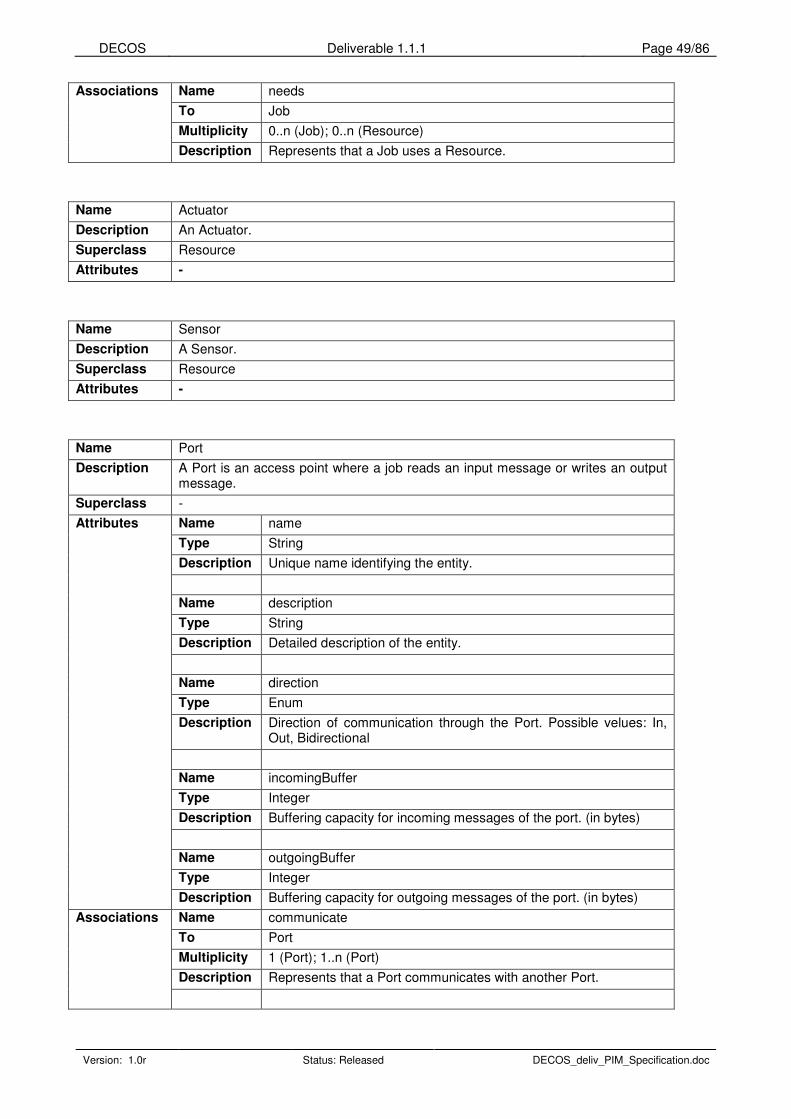
DECOS Deliverable 1.1.1 Page 49/86
Version: 1.0r Status: Released DECOS_deliv_PIM_Specification.doc
Name needs
To Job
Multiplicity 0..n (Job); 0..n (Resource)
Associations
Description Represents that a Job uses a Resource.
Name Actuator
Description An Actuator.
Superclass Resource
Attributes -
Name Sensor
Description A Sensor.
Superclass Resource
Attributes -
Name Port
Description A Port is an access point where a job reads an input message or writes an output message.
Superclass -
Name name
Type String
Description Unique name identifying the entity.
Name description
Type String
Description Detailed description of the entity.
Name direction
Type Enum
Description Direction of communication through the Port. Possible velues: In, Out, Bidirectional
Name incomingBuffer
Type Integer
Description Buffering capacity for incoming messages of the port. (in bytes)
Name outgoingBuffer
Type Integer
Attributes
Description Buffering capacity for outgoing messages of the port. (in bytes)
Name communicate
To Port
Multiplicity 1 (Port); 1..n (Port)
Description Represents that a Port communicates with another Port.
Associations

DECOS Deliverable 1.1.1 Page 50/86
Version: 1.0r Status: Released DECOS_deliv_PIM_Specification.doc
Name Read
To Message
Multiplicity 0..n (Port); 0..n (Message)
Description Represents that the State Variable is received in the Message.
Name Write
To Message
Multiplicity 0..n (Port); 0..n (Message)
Description Represents that the State Variable is sent in the Message.
Name isVisible
To StateVariable
Multiplicity 0..n (StateVariable); 0..n (Port)
Description Defines if a state variable is visible in the port.
Name StateMessagePort
Description A Port that transmits StateMessages.
Superclass Port
Name EventMessagePort
Description A Port that transmits EventMessages.
Superclass Port
Name StateVariable<T>
Description A State Variable represents a part of the state of a job.
Superclass -
Name name
Type String
Description Unique name identifying the entity.
Name description
Type String
Description Detailed description of the entity.
Name type
Type String
Description Data type of the State Variable.
Name fixedLength
Type Boolean
Description Marks whether the State Variable has fixed length.
Attributes
Name length

DECOS Deliverable 1.1.1 Page 51/86
Version: 1.0r Status: Released DECOS_deliv_PIM_Specification.doc
Type Integer
Description Length in bits. In case of variable length, it means maximal length.
Name initialValue
Type Depends on the type <T>
Description Initial value of the State Variable.
context StateVariable
inv: T.name = type
Name averagable
Type Boolean
Description Marks whether the values of the State variable can be averaged during an RDA algorithm.
Name -
To AcceptanceCriteria
Multiplicity 0..n (StateVariable); 0..n (AcceptanceCriteria)
Description Acceptance criteria of a received state variable. Can be used in an RDA or to define a State.
Name image
To StateMessage
Multiplicity 0..n (StateVariable); 0..n (StateMessage)
Description A State Message transmits the values of a state variable, that is, it serves as an image of the value.
Name delta
To EventMessage
Multiplicity 0..n (StateVariable); 0..n (EventMessage)
Description An Event Message transmits the change of a state variable.
Name -
To DeclaredState
Multiplicity 1..n (StateVariable); 0..n (DeclaredState)
Description A declared state consists of expressions restricting the values of state variables.
Name -
To Restriction
Multiplicity 0..n (StateVariable); 0..n (Restriction)
Description Represents an offline constraint for a state variable that can be used during analysis.
Name -
To Symptom
Multiplicity -
Description -
Associations

DECOS Deliverable 1.1.1 Page 52/86
Version: 1.0r Status: Released DECOS_deliv_PIM_Specification.doc
Name isVisible
To Port
Multiplicity 0..n (StateVariable); 0..n (Port)
Description Defines if the state variable is visible in a port.
Name DeclaredState
Description Represents a well defined state of the job. It can restrict the value of the state variables to satisfy a given expression.
Superclass -
Name name
Type String
Description Unique name identifying the entity.
Name description
Type String
Attributes
Description Detailed description of the entity.
Name -
To StateVariable
Multiplicity 1..n (StateVariable); 0..n (State)
Associations
Description A State consists of expressions restricting the values of StateVariables.
Name Message
Description Abstract message entity.
Superclass -
Name name
Type String
Description Unique name identifying the entity.
Name description
Type String
Description Detailed description of the entity.
Name transmissionType
Type Enum
Description Transmission type of the message.
Possible values are: Unicast, multicast or broadcast.
Name validitySpan
Type Duration
Description Length of the time the message remains valid.
Name senderStatus
Attributes
Type Boolean

DECOS Deliverable 1.1.1 Page 53/86
Version: 1.0r Status: Released DECOS_deliv_PIM_Specification.doc
Description Specifies if a sender-status information is transmitted along with the message.
Name depends
To Message
Multiplicity 0..n (Message); 0..n (Message)
Description Message depends on Message.
Name Read
To Port
Multiplicity 0..n (Message); 0..n (Port)
Description Represents that the State Variable is received in the Message.
Name Write
To Port
Multiplicity 0..n (Message); 0..n (Port)
Associations
Description Represents that the State Variable is sent in the Message.
Name StateMessage
Description A State Message.
Superclass Message
Attributes -
Name image
To StateVariable
Multiplicity 0..n (StateVariable); 0..n (StateMessage)
Associations
Description A State Message transmits the values of a State Variable, that is, it serves as an image of the value.
Name Event message
Description An Event Message.
Superclass Message
Attributes -
Name delta
To StateVariable
Multiplicity 0..n (StateVariable); 0..n (EventMessage)
Associations
Description An Event Message transmits the change of a State Variable.
Name MessagePartIdImage
Description Identifies the StateVariable in the Message.
Superclass -
Name PartID
Type String
Attributes
Description Identifies the StateVariable in the Message.
Name (association class) Associations
To StateVariable, StateMessage

DECOS Deliverable 1.1.1 Page 54/86
Version: 1.0r Status: Released DECOS_deliv_PIM_Specification.doc
Description -
Name MessagePartIdDelta
Description Identifies the state variable in the event message.
Superclass -
Name PartID
Type String
Attributes
Description Identifies the state variable in the event message.
Name (association class)
To StateVariable, EventMessage
Associations
Description -
Name DataStream
Description A Data Stream.
Superclass Message
Attributes -
Name OperatingMode
Description An operating mode of a DAS.
Superclass -
Name name
Type String
Description Unique name identifying the entity.
Name description
Type String
Attributes
Description Detailed description of the entity.
Name initial
To DAS
Multiplicity 1 (Operating mode); 1 (DAS)
Description Marks the initial operating mode of the DAS.
Name after
To Operating mode
Multiplicity 1 (Operating mode); 1..n (Operating mode)
Description Marks the possible operating mode changes.
Name runsIn
To Job
Multiplicity 1..n (OperatingMode); 1..n (Job)
Associations
Description Marks that a specific job runs in a specific operating mode.

DECOS Deliverable 1.1.1 Page 55/86
Version: 1.0r Status: Released DECOS_deliv_PIM_Specification.doc
Name Assertion
Description An abstract assertion expression.
Superclass -
Name name
Type String
Description Unique name identifying the entity.
Name description
Type String
Description Detailed description of the entity.
Name expression
Type String
Attributes
Description Defines the relationship in time, space, and value of state variables.
Name Symptom
Description An observable effect of a fault which is available for further handling by the system.
Superclass Assertion
Attributes -
Name -
To ONA
Description -
Name -
To StateVariable
Associations
Description Defines the relationship in time, space, and value of state variables.
Name Restriction
Description Represents an offline constraint for a StateVariable that can be used during analysis.
Superclass Assertion
Attributes -
Name -
To StateVariable
Multiplicity 0..n (Restriction); 0..n (StateVariable)
Associations
Description Defines the relationship in time, space, and value of state variables.
Name AcceptanceCriteria
Description AcceptanceCriteria of a received state variable. Can be used in an RDA or to define a State.
Superclass Assertion
Attributes -
Name - Associations
To StateVariable

DECOS Deliverable 1.1.1 Page 56/86
Version: 1.0r Status: Released DECOS_deliv_PIM_Specification.doc
Multiplicity 0..n (AcceptanceCriteria); 0..n (StateVariable)
Description Acceptance criteria of a received state variable. Can be used in an RDA or to define a State.
Name StateDeclaration
Description Declaration for the value of a state variable in a declared state.
Superclass Assertion
Attributes -
Name (as an association class)
To State, StateVariable
Associations
Description Defines the relationship in time, space, and value of state variables.
Name ONA
Description Out-of Norm Assertion.
Superclass Assertion
Attributes -
Name -
To Symptom
Associations
Description Defines the relationship in time, space, and value of symptoms.
5.2.2.2 Performance package
Name JobPerformance
Description Performance properties of a Job.
Superclass QoSCharacteristic
Name period
Type Duration
Description Execution period of job.
Name outgoingBandwidth
Type Integer
Description Bandwidth required to ensure extensibility for additional messages and data streams. This can be used to override the transformation in assigning the minimal required bandwidth, and to provide spare bandwidth to the Job with a possible extension in mind. (in bit/s)
Name deadline
Type Duration
Description The time instant until which the job should finish.
Name WCET
Type Duration
Attributes
Description Worst Case Execution Time
Associations Name JobPerformanceInOperatingMode

DECOS Deliverable 1.1.1 Page 57/86
Version: 1.0r Status: Released DECOS_deliv_PIM_Specification.doc
To Job, OperatingMode
Description Required performance parameters of a Job in a specific Operating mode.
Name TimeTriggeredJobPerformance
Description Performance properties of a time triggered job
Superclass JobPerformance
Name phase
Type Double
Attributes
Description Phase shift relation to construct phase-aligned transactions. Optional, percentage of period when to start, expressed as Real [0.0..1.0]
Name TimeTriggeredJobPerformanceInOperatingMode
To TimeTriggeredJob, OperatingMode
Associations
Description Required performance parameters of a time triggered job in a specific Operating mode.
Name EventTriggeredJobPerformance
Description Performance properties of an event triggered job
Superclass JobPerformance
Name priority
Type Double
Attributes
Description Phase shift relation to construct phase-aligned transactions. Optional, percentage of period when to start, expressed as Real [0.0..1.0]
Name EventTriggeredJobPerformanceInOperatingMode
To EventTriggeredJob, OperatingMode
Associations
Description Required performance parameters of a time triggered job in a specific Operating mode.
Name StateMessagePerformance
Description Performance properties of a State message.
Superclass QoSCharacteristic
Name period
Type Duration
Description Transmission period of the message.
Name phaseShift
Type Duration
Attributes
Description Phase shift relationship.
Name StateMessagePerformanceInOperatingMode
To State message, OperatingMode
Associations
Description Required performance parameters of a State message in a specific Operating mode.

DECOS Deliverable 1.1.1 Page 58/86
Version: 1.0r Status: Released DECOS_deliv_PIM_Specification.doc
Name EventMessagePerformance
Description Performance properties of an Event message.
Superclass QoSCharacteristic
Name priority
Type Integer
Description Abstract priority level. Can be mapped to concrete priority values of an implementation technology.
Name minimalInterarrivalTime
Type Duration
Description Minimum time between transmissions of the message.
Name meanInterarrivalTime
Type Duration
Description Mean time between transmissions of the message.
Name maximalInterarrivalTime
Type Duration
Description Maximal time between transmissions of the message.
Name serviceTime
Type Duration
Description Maximum time between fetch operations for the message.
Name latencyTime
Type Duration
Attributes
Description Maximum permitted time between transmission and reception of the message.
Name EventMessagePerformanceInOperatingMode
To EventMessage, OperatingMode
Associations
Description Required performance parameters of an Event message in a specific Operating mode.
Name DataStreamPerformance
Description Performance properties of a Data stream.
Superclass QoSCharacteristic
Name bandwidth
Type Integer
Description Bandwidth requirement of the data stream.
Effective bandwidth that is, protocol overhead and other platform specific overheads are not included. (in bit/s)
Name jitter
Type Duration
Description Jitter requirement of the data stream.
Attributes

DECOS Deliverable 1.1.1 Page 59/86
Version: 1.0r Status: Released DECOS_deliv_PIM_Specification.doc
Name latency
Type Duration
Description Latency requirement of a data stream.
Name DataStreamPerformanceInOperatingMode
To DataStream, OperatingMode
Associations
Description Required performance parameters of a Data stream in a specific Operating mode.
5.2.2.3 Dependability package
Name DASDependability
Description Dependability properties of a DAS.
Superclass
Name safetyIntegrityLevel
Type Integer
Description Safety Integrity Level (0-4).
Name redundancyDegree
Type Integer
Description Minimal redundancy degree for all components of the DAS.
(optional, should be filled in by the transformation based on dependability if empty)
Name availability
Type Double
Description Availability requirement of the DAS.
Name noSPOF
Type Boolean
Attributes
Description Expresses that a DAS cannot have a Single Point of Failure.
Name DASDependabilityInOperatingMode
To DAS, OperatingMode
Associations
Description Required dependability parameters of a DAS in a specific Operating mode.
Name JobDependability
Description Dependability properties of a Job.
Superclass
Name failureMode
Type Enum
Attributes
Description Failure mode of the Job. Possible values are e.g.: fail-silent, fail-safe
Name JobDependabilityInOperatingMode
To Job, OperatingMode
Associations
Description Required dependability parameters of a Job in a specific Operating mode.
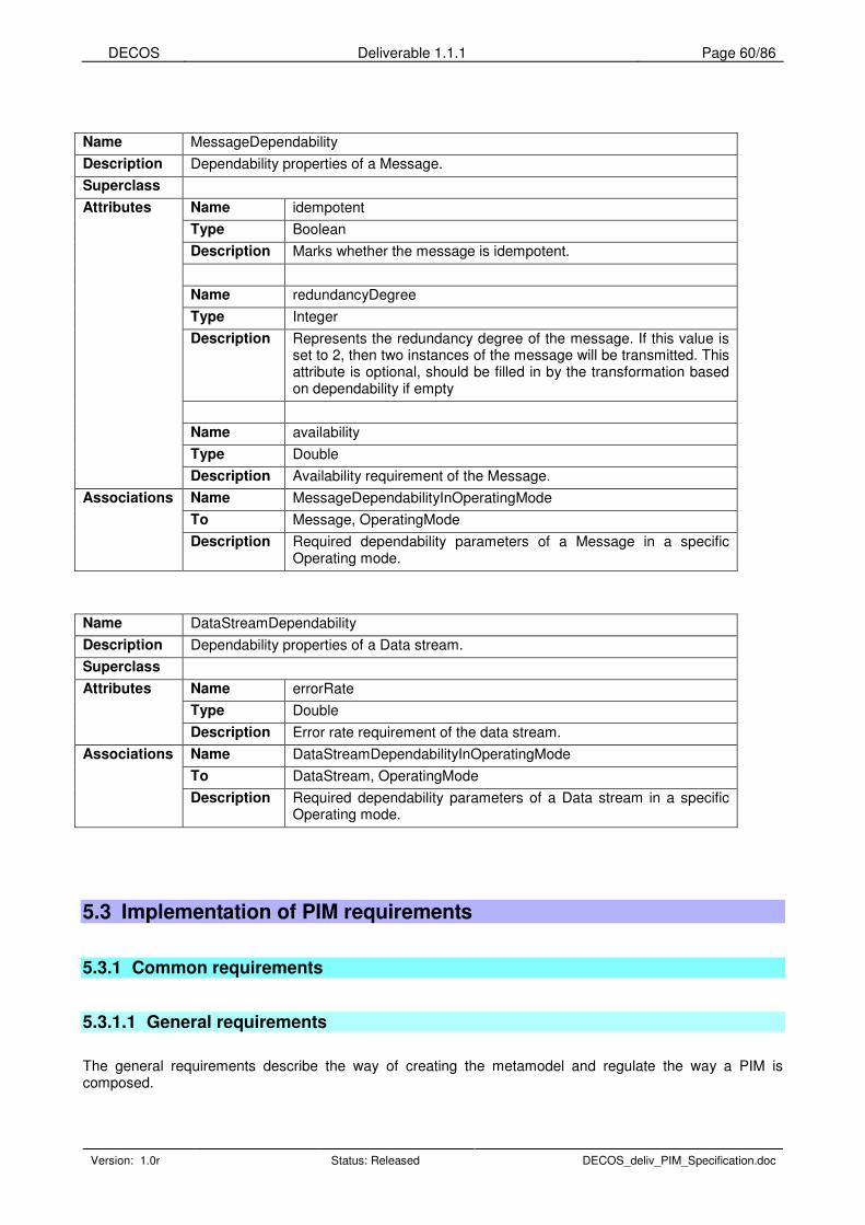
DECOS Deliverable 1.1.1 Page 60/86
Version: 1.0r Status: Released DECOS_deliv_PIM_Specification.doc
Name MessageDependability
Description Dependability properties of a Message.
Superclass
Name idempotent
Type Boolean
Description Marks whether the message is idempotent.
Name redundancyDegree
Type Integer
Description Represents the redundancy degree of the message. If this value is set to 2, then two instances of the message will be transmitted. This attribute is optional, should be filled in by the transformation based on dependability if empty
Name availability
Type Double
Attributes
Description Availability requirement of the Message.
Name MessageDependabilityInOperatingMode
To Message, OperatingMode
Associations
Description Required dependability parameters of a Message in a specific Operating mode.
Name DataStreamDependability
Description Dependability properties of a Data stream.
Superclass
Name errorRate
Type Double
Attributes
Description Error rate requirement of the data stream.
Name DataStreamDependabilityInOperatingMode
To DataStream, OperatingMode
Associations
Description Required dependability parameters of a Data stream in a specific Operating mode.
5.3 Implementation of PIM requirements
5.3.1 Common requirements
5.3.1.1 General requirements
The general requirements describe the way of creating the metamodel and regulate the way a PIM is composed.

DECOS Deliverable 1.1.1 Page 61/86
Version: 1.0r Status: Released DECOS_deliv_PIM_Specification.doc
ID: 1.1.1_GEN_01 Name: requirements
Description: The PIM shall represent the requirements for the DASs.
Solution: The PIM does not describe implementation details, only the requirements for the system.
ID: 1.1.1_GEN_02 Name: platform_independency
Description: The PIM shall be platform-independent.
Solution: The PIM does not contain any references to platforms or technologies. After finalizing a PIM the elements can be marked to give control information to the PIM-PSM transformation process on the deployment of a function onto a particular platform.
ID: 1.1.1_GEN_03 Name: paradigm_independency
Description: The PIM shall be paradigm-independent.
Solution: The concepts in the PIM do not restrict the implementation to either TT or ET. A system described by the PIM can be implemented by using any feasible technology.
ID: 1.1.1_GEN_04 Name: description
Description: Every entity shall have a description / specification field.
Solution: Every entity has a description field where documentation can be inserted. The actual content of documentation is subject of a later agreement. It will contain of informal and / or formal descriptions. (In case of subclasses, description isn’t redefined because it inherits it from the parent)
ID: 1.1.1_GEN_05 Name: name
Description: Every entity shall have a name field.
Solution: Every entity has a name field. Assuring that this name is unique is the task of the modeling tool, or a syntax checker. (In case of subclasses, name isn’t redefined because it inherits it from the parent)
ID: 1.1.1_GEN_06 Name: verifiability
Description: The PIM shall be verifiable in order to enable component-based verification of subsystems. This may affect in particular the technology/methodology decision.
Solution: UML is an open standard, and the standard XMI exchange format assures the interoperability of different tools, moreover it supports the transformation of models to any other format that can be verified with existing or future verification tools.
ID: 1.1.1_GEN_07 Name: extensibility
Description: The PIM shall be modifiable and extensible.
Solution: The proposed metamodel can be modified and extended later as a need arises for changing. Moreover, the PIM is generic enough to be able to describe a wide variety of systems.
ID: 1.1.1_GEN_08 Name: xml_syntax
Description: XML based syntax definition of the metamodel.
Solution: XMI serves as an XML based exchange format as it is standardized and most UML modeling tools support it. Conformance can be checked using a DTD, moreover, a rigorous syntax check assures the compliance with the metamodel.
5.3.1.2 Technology and design methodology requirements
The following table lists the technologies and design methodologies that the PIM shall / should support in order to be able to use it in the everyday work of project partners. The transformation will transform the PIM to the input model of these supported technologies and methodologies.
ID: 1.1.1_TECHN_01 Name: MATLAB_Simulink
Description: MATLAB/Simulink support shall be provided.
Solution: The proposed metamodel is a structured ontology of the DECOS related concepts. It is independent of the actual modeling paradigm used. The UML profile is one type of representation of the concepts contained in the metamodel. One can specialize Simulink to enhost the metamodel concept independently of the UML profile. Moreover, a UML model compliant with the profile can be transformed to Simulink if needed.

DECOS Deliverable 1.1.1 Page 62/86
Version: 1.0r Status: Released DECOS_deliv_PIM_Specification.doc
ID: 1.1.1_TECHN_02 Name: Simulink_Stateflow
Description: Simulink/Stateflow support shall be provided.
Solution: The proposed metamodel is a structured onthology of the DECOS related concepts. It is independent of the actual modeling paradigm used. The UML profile is one type of representation of the concepts contained in the metamodel. One can specialize Simulink to enhost the metamodel concept independently of the UML profile. Moreover, a UML model compliant with the profile can be transformed to Simulink if needed.
ID: 1.1.1_TECHN_03 Name: Simulink_Coder
Description: MATLAB/Simulink-Coder support shall be provided.
Solution: The proposed metamodel is a structured onthology of the DECOS related concepts. It is independent of the actual modeling paradigm used. The UML profile is one type of representation of the concepts contained in the metamodel. One can specialize Simulink to enhost the metamodel concept independently of the UML profile. Moreover, a UML model compliant with the profile can be transformed to Simulink if needed.
ID: 1.1.1_TECHN_04 Name: SCADE dataflow
Description: SCADE support shall be provided.
Solution: Esterel Technologies are currently developing a UML profile. As soon as it will be ready, a transformation between the PIM and that profile can be developed.
ID: 1.1.1_TECHN_05 Name: SCADE CG
Description: SCADE Code Generator support shall be provided.
Solution: Esterel Technologies are currently developing a UML profile. As soon as it will be ready, a transformation between the PIM and that profile can be developed.
ID: 1.1.1_TECHN_06 Name: SCADE SSM
Description: SCADE Safe State Machines support shall be provided.
Solution: Esterel Technologies are currently developing a UML profile. As soon as it will be ready, a transformation between the PIM and that profile can be developed.
ID: 1.1.1_TECHN_07 Name: TTP_support
Description: All services, functionalities and tools of TTP shall be supported by all DECOS developments.
Solution: The PIM represents generic entities that build up a system that can be implemented on any platform, including TTP.
5.3.1.3 Identification of standards
Since the PIM is platform independent it shall not support specific technology standards, but it should cover the functionality of the following standards in order to help the application of the standard during the design.
ID: 1.1.1_STAND_01 Name: UML_SPT
Description: The PIM shall support the UML Profile for Schedulability, Performance, and Time Specification
Solution: The PIM does not contradict the guidelines of the SPT profile, the elements defined can be expressed as specialized types of that profile. On the other hand, the SPT profile defines not only the performance requirements of a system but the performance provided by resources, which is not the aim of the PIM.
Moreover, the UML Profile for QoS (which is used in the PIM) uses the concepts defined in the Profile for PST.
ID: 1.1.1_STAND_02 Name: TTP/C
Description: The PIM shall support the TTP/C standard.
Solution: The PIM represents generic entities that build up a system that can be implemented on any platform, including TTP.
ID: 1.1.1_STAND_03 Name: CAN
Description: The PIM shall support the CAN Specification Version 2.0.

DECOS Deliverable 1.1.1 Page 63/86
Version: 1.0r Status: Released DECOS_deliv_PIM_Specification.doc
Solution: The PIM represents generic entities that build up a system that can be implemented on any platform, including CAN.
ID: 1.1.1_STAND_04 Name: LIN
Description: The PIM shall support the LIN Specification Package Revision 1.3.
Solution: The PIM represents generic entities that build up a system that can be implemented on any platform, including LIN.
ID: 1.1.1_STAND_05 Name: Profibus
Description: The PIM shall support the Profibus standard.
Solution: The PIM represents generic entities that build up a system that can be implemented on any platform, including Profibus.
ID: 1.1.1_STAND_06 Name: FlexRay
Description: FlexRay support shall be provided.
Solution: The PIM represents generic entities that build up a system that can be implemented on any platform, including FlexRay.
ID: 1.1.1_STAND_07 Name: internet_protocol
Description: The PIM shall support Internet Protocols (e.g., TCP/IP, UDP).
Solution: Providing support for specific protocols is the task of the PIL, message transmissions described in the PIM can be implemented over any protocol, including TCP/IP or UDP.
ID: 1.1.1_STAND_08 Name: DO-178B
Description: DO-178B support shall be provided.
Solution: This happens by transforming the PIM of critical parts to DO-178D compliant tools.
ID: 1.1.1_STAND_09 Name: compliance
Description: To satisfy all validation & verification, safety, certification and legal requirements all tools, applications, software and hardware developed in DECOS subprojects shall show compliance to the documents relevant to safety critical system design in the target field of application.
Solution: This happens by transforming the PIM of critical parts to DO-178D compliant tools. Additionally an analysis will be provided comparing the DECOS metamodel and designed UML profile with SysML an evolving standard in the field.
5.3.2 Functional requirements
5.3.2.1 DAS related requirements
The system consists of DASs that can interact and cooperate.
ID: 1.1.1_FUNC_DAS_01 Name: das
Description: The PIM shall represent DASs.
Solution: The PIM has an entity called DAS that represents DASs.
ID: 1.1.1_FUNC_DAS_02 Name: das_type
Description: The PIM shall represent DAS types.
Solution: DAS has an attribute called type that describes the DAS type.
ID: 1.1.1_FUNC_DAS_03 Name: das_interface
Description: The PIM shall represent the interface of DASs to the environment and to each other.
Solution: A DAS consists of jobs that can have Interfaces to the environment and each other.
ID: 1.1.1_FUNC_DAS_04 Name: das_operating_mode
Description: The PIM shall represent operating modes of DASs.
Solution: There is an entity called OperatingMode that can be attached to a DAS.
ID: 1.1.1_FUNC_DAS_05 Name: das_initial_operating_mode

DECOS Deliverable 1.1.1 Page 64/86
Version: 1.0r Status: Released DECOS_deliv_PIM_Specification.doc
Description: The PIM shall represent the initial operating mode of DASs.
Solution: The association called “initial” between DAS and OperatingMode shows the initial operating mode.
ID: 1.1.1_FUNC_DAS_06 Name: das_operating_mode_change
Description: The PIM shall represent operating mode changes of DASs.
Solution: The association “after” between OperatingModes shows the possible operating mode changes.
5.3.2.2 Job related requirements
DASs are composed of communicating jobs.
ID: 1.1.1_FUNC_JOB_01 Name: job
Description: The PIM shall represent jobs.
Solution: The PIM has an entity called Job that represents Jobs.
ID: 1.1.1_FUNC_JOB_02 Name: job_interface
Description: The PIM shall represent the interface of jobs.
Solution: Jobs can have interfaces to the environment and each other.
ID: 1.1.1_FUNC_JOB_03 Name: job_produce/publish_property
Description: The PIM shall represent the produce/publish property of jobs.
Solution: The messages and data streams produced by a job can be found through its Interfaces, Ports and the State variables that are mapped to messages.
ID: 1.1.1_FUNC_JOB_04 Name: job_consumer/subscriber_property
Description: The PIM shall represent the consumer/subscribe property of jobs.
Solution: The messages and data streams consumed by a job can be found through its Interfaces, Ports and the State variables that are mapped to messages.
5.3.2.3 Message related requirements
ID: 1.1.1_FUNC_MESS_01 Name: message
Description: The PIM shall represent messages.
Solution: The PIM has an entity called Message that represents Messages. Moreover, it has subtypes StateMessage and EventMessage.
ID: 1.1.1_FUNC_MESS_02 Name: message_elements
Description: Messages shall consist of primitive elements.
Solution: Both StateMessages and EventMessages consist of StateVariables that can be thought as elements of messages.
ID: 1.1.1_FUNC_MESS_03 Name: message_producer
Description: The PIM shall represent the producers of a specific message.
Solution: The Job producing a message can be found through its Ports and Interfaces.
ID: 1.1.1_FUNC_MESS_04 Name: message_consumer
Description: The PIM shall represent the consumers of a specific message.
Solution: The Job consuming a message can be found through its Ports and Interfaces.
ID: 1.1.1_FUNC_MESS_05 Name: message_transmission_type
Description: The PIM shall represent message transmission types.
Solution: Message has an attribute called transmission type that describes the transmission type of a Message.
ID: 1.1.1_FUNC_MESS_06 Name: message_validity_span
Description: The PIM shall represent the validity span of a specific message.

DECOS Deliverable 1.1.1 Page 65/86
Version: 1.0r Status: Released DECOS_deliv_PIM_Specification.doc
Solution: Message has an attribute called validity span that describes the validity span of a Message.
ID: 1.1.1_FUNC_MESS_07 Name: message_RDA
Description: The PIM shall represent the properties of a message that are needed to decide the Replica Determinism Algorithm if needed.
Solution: Since messages can consist of multiple data elements that can have different RDA requirements, these are placed in StateVariables. StateVariable has an attribute called averagable that describes whether the values of multiple instances of the data can be averaged or not (e.g. a variable consisting of binary flags can not be averaged). Moreover, expressions called Acceptance criteria can be attached. These together should make it possible to determine the possible RDA algorithms in a specific case, from which one should be chosen during the transformation.
ID: 1.1.1_FUNC_MESS_08 Name: message_types
Description: Messages shall have types.
Solution: The composite type of a message is determined by its consisting elements.
ID: 1.1.1_FUNC_MESS_09 Name: message_job-job
Description: Job-job messages shall have subtypes.
Solution: The entity Message has two subtypes, namely State message and Event message.
ID: 1.1.1_FUNC_MESS_10 Name: message_dependency
Description: The PIM shall represent a “depends” relation amongst messages.
Solution: There can be an association between Messages called depends, that expresses this relation.
ID: 1.1.1_FUNC_MESS_11 Name: inter-system_communication
Description: The Communication Bus System shall support all types of inter-system communication including periodic and aperiodic data transfer.
Solution: The entity message has two subtypes, namely state message and event message. State message is for periodic, event message is for aperiodic data transfer.
ID: 1.1.1_FUNC_MESS_12 Name: message_transmission_mechanism
Description: The PIM shall represent the transmission mechanism of messages.
Solution: The transmission mechanism of a message element is determined by the association it is connected to the message (namely read or write). Transmission mechanism of the message depends on the transmission mechanism of its elements.
ID: 1.1.1_FUNC_MESS_13 Name: message_reception_mechanism
Description: The PIM shall represent the reception mechanism of messages.
Solution: The reception mechanism of a message element is determined by the association it is connected to the message (namely read or write). Reception mechanism of the message depends on the reception mechanism of its elements.
ID: 1.1.1_FUNC_MESS_14 Name: message_sender_status
Description: The PIM shall represent the sender status of messages.
Solution: Message has an attribute called sender status that describes the need for a senderStatus in a Message.
ID: 1.1.1_FUNC_MESS_15 Name: message_phase_shift
Description: The PIM shall represent the phase shift of messages.
Solution: State message has an attribute called phaseShift that describes the phase shift of a State message.
5.3.2.4 Element related requirements
ID: 1.1.1_FUNC_ELEM_01 Name: element
Description: The PIM shall represent primitive elements.
Solution: Messages consist of the representations of StateVariables thus they can be thought of as elements of message.
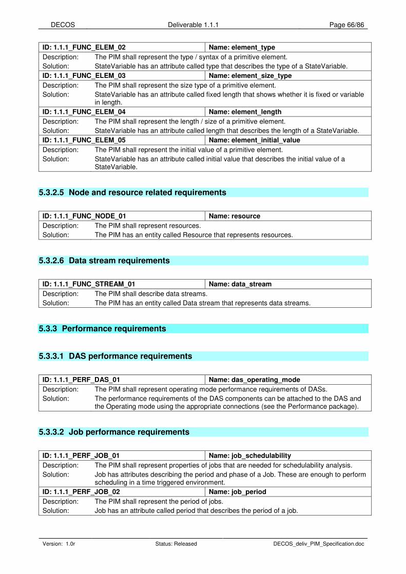
DECOS Deliverable 1.1.1 Page 66/86
Version: 1.0r Status: Released DECOS_deliv_PIM_Specification.doc
ID: 1.1.1_FUNC_ELEM_02 Name: element_type
Description: The PIM shall represent the type / syntax of a primitive element.
Solution: StateVariable has an attribute called type that describes the type of a StateVariable.
ID: 1.1.1_FUNC_ELEM_03 Name: element_size_type
Description: The PIM shall represent the size type of a primitive element.
Solution: StateVariable has an attribute called fixed length that shows whether it is fixed or variable in length.
ID: 1.1.1_FUNC_ELEM_04 Name: element_length
Description: The PIM shall represent the length / size of a primitive element.
Solution: StateVariable has an attribute called length that describes the length of a StateVariable.
ID: 1.1.1_FUNC_ELEM_05 Name: element_initial_value
Description: The PIM shall represent the initial value of a primitive element.
Solution: StateVariable has an attribute called initial value that describes the initial value of a StateVariable.
5.3.2.5 Node and resource related requirements
ID: 1.1.1_FUNC_NODE_01 Name: resource
Description: The PIM shall represent resources.
Solution: The PIM has an entity called Resource that represents resources.
5.3.2.6 Data stream requirements
ID: 1.1.1_FUNC_STREAM_01 Name: data_stream
Description: The PIM shall describe data streams.
Solution: The PIM has an entity called Data stream that represents data streams.
5.3.3 Performance requirements
5.3.3.1 DAS performance requirements
ID: 1.1.1_PERF_DAS_01 Name: das_operating_mode
Description: The PIM shall represent operating mode performance requirements of DASs.
Solution: The performance requirements of the DAS components can be attached to the DAS and the Operating mode using the appropriate connections (see the Performance package).
5.3.3.2 Job performance requirements
ID: 1.1.1_PERF_JOB_01 Name: job_schedulability
Description: The PIM shall represent properties of jobs that are needed for schedulability analysis.
Solution: Job has attributes describing the period and phase of a Job. These are enough to perform scheduling in a time triggered environment.
ID: 1.1.1_PERF_JOB_02 Name: job_period
Description: The PIM shall represent the period of jobs.
Solution: Job has an attribute called period that describes the period of a job.
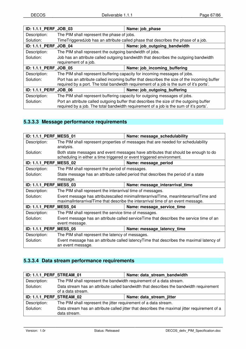
DECOS Deliverable 1.1.1 Page 67/86
Version: 1.0r Status: Released DECOS_deliv_PIM_Specification.doc
ID: 1.1.1_PERF_JOB_03 Name: job_phase
Description: The PIM shall represent the phase of jobs.
Solution: TimeTriggeredJob has an attribute called phase that describes the phase of a job.
ID: 1.1.1_PERF_JOB_04 Name: job_outgoing_bandwidth
Description: The PIM shall represent the outgoing bandwidth of jobs.
Solution: Job has an attribute called outgoing bandwidth that describes the outgoing bandwidth requirement of a job.
ID: 1.1.1_PERF_JOB_05 Name: job_incoming_buffering
Description: The PIM shall represent buffering capacity for incoming messages of jobs.
Solution: Port has an attribute called incoming buffer that describes the size of the incoming buffer required by a port. The total bandwidth requirement of a job is the sum of it’s ports’.
ID: 1.1.1_PERF_JOB_06 Name: job_outgoing_buffering
Description: The PIM shall represent buffering capacity for outgoing messages of jobs.
Solution: Port an attribute called outgoing buffer that describes the size of the outgoing buffer required by a job. The total bandwidth requirement of a job is the sum of it’s ports’.
5.3.3.3 Message performance requirements
ID: 1.1.1_PERF_MESS_01 Name: message_schedulability
Description: The PIM shall represent properties of messages that are needed for schedulability analysis.
Solution: Both state messages and event messages have attributes that should be enough to do scheduling in either a time triggered or event triggered environment.
ID: 1.1.1_PERF_MESS_02 Name: message_period
Description: The PIM shall represent the period of messages.
Solution: State message has an attribute called period that describes the period of a state message.
ID: 1.1.1_PERF_MESS_03 Name: message_interarrival_time
Description: The PIM shall represent the interarrival time of messages.
Solution: Event message has attributescalled minimalInterarrivalTime, meanInterarrivalTime and maximalInterarrivalTime that describe the interarrival time of an event message.
ID: 1.1.1_PERF_MESS_04 Name: message_service_time
Description: The PIM shall represent the service time of messages.
Solution: Event message has an attribute called serviceTime that describes the service time of an event message.
ID: 1.1.1_PERF_MESS_05 Name: message_latency_time
Description: The PIM shall represent the latency of messages.
Solution: Event message has an attribute called latencyTime that describes the maximal latency of an event message.
5.3.3.4 Data stream performance requirements
ID: 1.1.1_PERF_STREAM_01 Name: data_stream_bandwidth
Description: The PIM shall represent the bandwidth requirement of a data stream.
Solution: Data stream has an attribute called bandwidth that describes the bandwidth requirement of a data stream.
ID: 1.1.1_PERF_STREAM_02 Name: data_stream_jitter
Description: The PIM shall represent the jitter requirement of a data stream.
Solution: Data stream has an attribute called jitter that describes the maximal jitter requirement of a data stream.

DECOS Deliverable 1.1.1 Page 68/86
Version: 1.0r Status: Released DECOS_deliv_PIM_Specification.doc
ID: 1.1.1_PERF_STREAM_03 Name: data_stream_latency
Description: The PIM shall represent the latency requirement of a data stream.
Solution: Data stream has an attribute called latency that describes the latency requirement of a data stream.
5.3.4 Dependability requirements
5.3.4.1 DAS dependability requirements
ID: 1.1.1_DEP_DAS_01 Name: das_operating_mode
Description: The PIM shall represent the operating mode dependability requirements of DASs.
Solution: The dependability requirements of the DAS components can be attached to the DAS and the Operating mode using the appropriate connections (see the Dependability package).
ID: 1.1.1_DEP_DAS_02 Name: das_sil
Description: The PIM shall represent the Safety Integrity Level (SIL) of DASs.
Solution: DAS has an attribute called safety integrity level that describes the safety integrity level of a DAS.
ID: 1.1.1_DEP_DAS_03 Name: dual_redundancy
Description: All system functions shall be implemented with at least dual redundancy, except if the aircraft can be dispatched following loss of the function, without any time limitation and without any operational consequence.
Solution: DAS has an attribute called redundancyDegree that describes the redundancy degree of a DAS.
ID: 1.1.1_DEP_DAS_04 Name: das_failure_mode
Description: The PIM shall represent the failure mode of DASs.
Solution: DAS has an attribute called failure mode that describes the failure mode of a DAS.
5.3.4.2 Job dependability requirements
ID: 1.1.1_DEP_JOB_01 Name: job_failure_mode
Description: The PIM shall represent the failure mode of a job.
Solution: Job has an attribute called failure mode that describes the failure mode of a job.
5.3.4.3 Message dependability requirements
ID: 1.1.1_DEP_MESS_01 Name: message_idempotency
Description: The PIM shall represent whether a message is idempotent.
Solution: Message has an attribute called idempotency that describes whether the message is idempotent.
ID: 1.1.1_DEP_MESS_02 Name: message_redundancy
Description: The PIM shall represent the redundancy degree of messages.
Solution: Message has an attribute called redundancy degree that describes the redundancy degree of the message.
5.3.4.4 Data stream dependability requirements

DECOS Deliverable 1.1.1 Page 69/86
Version: 1.0r Status: Released DECOS_deliv_PIM_Specification.doc
ID: 1.1.1_DEP_STREAM_01 Name: data_stream_error_rate
Description: The PIM shall represent the error rate requirement of a data stream.
Solution: Data stream has an attribute called error rate that describes the error rate requirement of the data stream.
5.3.4.5 Diagnostic Requirements
The integrated diagnostic services of the DECOS integrated architecture support both application and system specific diagnosis. The following table defines the requirements that are necessary to describe the diagnostic services.
ID: 1.1.1_DEP_DIAG_01 Name: symptom_name
Description: The symptom name should uniquely identify the symptom in the DAS.
Solution: The PIM has an entity called Symptom that represents symptoms.
ID: 1.1.1_DEP_DIAG_02 Name: symptom_expression
Description: The symptom expression should define the relationship in time, space, and value of interface state variables.
Solution: Symptom has an attribute called expression that holds the expression of the symptom.
ID: 1.1.1_DEP_DIAG_03 Name: ONA_name
Description: The ONA name should uniquely identify the ONA in the DAS.
Solution: The PIM has an entity called ONA that represents ONAs. As every entity in the PIM, it has a name attribute that identifies it.
ID: 1.1.1_DEP_DIAG_04 Name: ONA_expression
Description: The ONA expression defines the relationship in time, space, and value of symptoms.
Solution: ONA is a subtype of Assertion which has an attribute called expression that holds the expression of the ONA.
ID: 1.1.1_DEP_DIAG_05 Name: job_diagnostic_output
Description: The diagnostic output of the job is optional diagnostic information, provided in addition to the diagnostic information gathered at the architecture level.
Solution: On Interface type is Diagnostic and Management interface that can be used to transmit diagnostic information. Every job can have this type of interface.

DECOS Deliverable 1.1.1 Page 70/86
Version: 1.0r Status: Released DECOS_deliv_PIM_Specification.doc
6 Relation to domain specific standards
6.1 Importance of standards
DECOS provides a dependable architecture and development framework for embedded systems. During the development process following the DECOS approach, the PIM metamodel and the tools that implement the PIM metamodel play a very important role. This is the primary means for capturing the requirements. Therefore the PIM metamodel, the PIM and the PIM development tools are related to some extent to the standards of embedded, dependable, real-time applications.
Since the PIM metamodel and the PIM model are platform independent they must not support specific technology standards, but they should cover the functionality of the corresponding standards in order to help the application of the standard during the design.
Related standards can be divided into two main groups:
1. Standards that describe the development of dependable, real-time, embedded systems. They describe the different steps of the development and prescribe some tasks that has to be done at a given development step.
2. Standards that describe the way of metamodeling and model based development. They are mainly technology related standards and gives help implement a standardized, up-to-date modeling technology that yields models that can be interchanged between different modeling and development tools.
6.2 Development standards
6.2.1 DO-178B
DO-178B, Software Considerations in Airborne Systems and Equipment Certification, published by RTCA, provides guidelines for the production of airborne systems equipment software. It is used internationally to specify the safety and airworthiness of software for avionics systems. It describes techniques and methods appropriate to ensure the integrity and reliability of such software. It has been used to secure FAA approval of digital computer software.
The guidelines for software development and verification are described for each of six software levels. Level A is used when anomalous behavior causes catastrophic failure condition. Level E is used when anomalous behavior has no effect on operational capacity. Guidelines are provided in the areas of software planning, development, verification, configuration management, quality assurance, certification, and maintenance. The guideline defines processes where safety is the Focus. The processes are imposed so that safety is designed into a product. A System Safety Assessment process is required to associate criticality levels with the various system elements.
The guidelines impose criteria on the software life-cycle processes to ensure that the development results in a safe system. The processes can be categorized as developmental or integral. Figure 9 illustrates the basic elements of a software life-cycle model, independent from a prescribed software engineering method. This model reflects the basic activities of capturing the requirements and performing design, implementation, and integration. It is not intended to imply the "waterfall" model or a particular development methodology. The relative size of each activity is not meant to be representative of any collected data; it is strictly used to illustrate the concurrent nature of the activities in the software development process. The software development activities are the main product-oriented activities and can have some degree of parallelism. The other integral processes (e.g., verification, configuration management, quality assurance) provide

DECOS Deliverable 1.1.1 Page 71/86
Version: 1.0r Status: Released DECOS_deliv_PIM_Specification.doc
software engineering process support that helps ensure the completeness and quality of the software development activities. A productive process uses a constructive approach that satisfies the completion criteria of the integral processes (e.g., testing, verification, etc.) during the software development activities.
Figure 9: Development life-cycle according to DO-178B
There is also a requirement to perform tool qualification if a tool is used to automate software development processes that are typically performed by humans. Tool Operational Requirements must be provided, and the tool must be verified against the operational requirements.
The PIM and the PIM metamodel themselves should allow their usage in a product development life-cycle that corresponds to DO-178B. Since PIM construction is mainly a mean for requirement formulation, the tools that implement the PIM metamodel for some modeling language in order to create the PIM of a DECOS application are not used to automate software development processes. Therefore these tools should not be certified according to DO-178B.
Actually, DO-178B support happens by transforming the PIM of critical parts to DO-178D compliant tools that can be used to automate some software development steps like code generation. The models generated by the suggested approach will be transformed during the synthesis process to the input language of a certified paradigm in a human readable form. This way the approach supports the reuse of existing certified industrial tools without the immediate need to certify the entire tool chain used in the workflow. Obviously this does not exclude the certification of the tools used in the initial phases of the workflow if needed, but it is unfeasible in the framework of the current project. As a summary, certification will be assured by reusing best practice of certified tools.
6.2.2 ISO/IEC 61508
The international standard IEC 61508, Functional Safety of Electrical/Electronic/ Programmable Electronic (E/E/PE) safety-related systems aims to:
♦ release the potential of E/E/PE technology to improve both safety and economic performance;
♦ enable technological developments to take place within an overall safety framework;
♦ provide a technically sound, system based approach, with sufficient flexibility for the future;
♦ provide a risk-based approach for determining the required performance of safety-related systems;
♦ provide a generically-based standard that can be used directly by industry but can also help with developing sector standards (e.g. machinery, process chemical plants, medical or rail) or product standards (e.g. power drive systems);

DECOS Deliverable 1.1.1 Page 72/86
Version: 1.0r Status: Released DECOS_deliv_PIM_Specification.doc
♦ provide a means for users and regulators to gain confidence when using computer based technology;
♦ provide requirements based on common underlying principles
IEC 61508 covers the whole safety lifecycle of an installation from initial concept, to hazard analysis and risk assessment, development of the safety requirements, specification, design and implementation, operation and maintenance, and modification, to final decommissioning and/or disposal.
The relation of IEC 61508 to PIM and PIM metamodel is identical with that of DO-178B; it makes its application possible but it does not have direct implication on PIM. A concrete support for the application of IEC 61508 is the possibility to define the SIL levels the standard suggests to use.
6.2.3 SAExx
For the full list of these standards see the requirement specification of PIM (Section 3 of this document). The correspondence to these standards occurs similarly to the case of DO-178B.
6.2.4 Implementation technology standards
Implementation technology standards are a subset of the development technology standards, they correspond to the implementation phase of the development. Despite of this fact there are a few from the point of view of DECOS important standards (see Section 3) we have to mention:
♦ CAN
♦ Profibus
♦ LIN
♦ FlexRay
♦ TTP
They are all related to possible implementation platforms. Since the PIM is platform independent it should not contain any platform specific details and these standards do not relate to the PIM metamodel directly. However each implementation on the above platforms should be described by PIM, therefore the PIM metamodel should cover the union of abstracted features of these platforms in order to support all possible constructs of them.
6.3 SysML
6.3.1 Introduction
The System Modeling Language (SysML) is a general-purpose modeling language for systems engineering applications. SysML aims to support the specification, analysis, design, verification and validation of a broad range of large and complex systems that include hardware and software components.
SysML is being defined by the “SysML Partners” which is an informal partnership of organizations, including large and well-known companies like IBM, Motorola, I-Logix, Gentleware, Telelogic, from the field of aerospace and defense: Boeing, Nasa/Jet Propulsion Laboratory, BAE Systems, Northrop Grumman, THALES etc. (the whole list of SysML partners is enumerated on the www.sysml.org website).

DECOS Deliverable 1.1.1 Page 73/86
Version: 1.0r Status: Released DECOS_deliv_PIM_Specification.doc
The original aim of the SysML initiative was to customize the Unified Modeling Language (UML) for systems engineering applications. This collaboration resulted in the submission of SysML in response to the OMG’s UML for Systems Engineering Request for Proposal (RFP) issued in 2003.
The latest available version of SysML was submitted to the OMG on the 11th of October 2004., It is available
for download from the above mentioned website.
SysML is architecturally aligned with the evolving ISO AP-233 data interchange standard for systems engineering in order to support interoperability between systems engineering tools and other tools that interface with them.
Since our aim in the DECOS project is to propose a PIM metamodel, which is able to describe complex, embedded, real-time systems from high-level, system wide view, it was obvious to survey the SysML metamodel from the point of view of dependable embedded system design. Our aim was to compare our PIM metamodel with the SysML to detect the newly defined PIM metamodel’s possible defects or to prove its completeness.
The following section gives a brief overview of the SysML metamodel, placing emphasis mainly on the dependable, embedded system specific aspects of this novel proposal. In conclusion a table summarizes the main novelties of SysML with a reference to its analogous PIM elements/properties.
6.3.2 SysML metamodel
The proposed SysML specification is defined as an extension of the UML 2.0 Superstructure Specification (see Figure 10), this way reuses the UML syntax and semantics roles.
<<metamodel>>MOF
<<metamodel>>
UML
<<instanceOf>>
<<import>>
<<instanceOf>>
<<modelLibrary>>
SysML
<<userModel>>
XYZsystem<<reuse>>
<<instanceOf>>
<<metamodel>>
SysML
Figure 10: SysML extension of UML
As shown on the Figure 10 SysML reuses a subset of UML (<<IMPORT>> relationship) and creates extensions to support the specific requirements needed to model complex engineering systems. Several extension mechanisms are used including stereotypes, metaclasses and model libraries. The SysML

DECOS Deliverable 1.1.1 Page 74/86
Version: 1.0r Status: Released DECOS_deliv_PIM_Specification.doc
stereotypes and metaclasses are instantiated in the <<USERMODEL>> while classes are grouped into subclasses in the <<MODELLIBRARY>>.
The SysML package structure is shown in more details on the Figure 11. Among these packages there are some imported from the UML without any modification, like State Machines, Interactions and Use Cases.
New SysML packages are Requirements, Parametrics and Allocation. The Assemblies package uses structured classes from COMPOSITESTRUCTURES (UML2.0) and contains some minor extensions.
Common
BehaviorsUse Cases
Actions Activities
StateMachines
Auxillary
Constructs
Classes
Requirements
Assemblies
Interactions Parametrics
Allocation
Profiles
<<metamodel>>
SysML
Figure 11: SysML package structure
6.3.3 Comparison of SysML and DECOS PIM
The approach of SysML and the DECOS PIM is somewhat different. SysML targets the definition of a general-purpose modeling language, while the PIM is targeted for the description of distributed, dependable, embedded systems. The designers of SysML do not intend to be more specific than this as can be seen in the SysML proposal:
“This specification defines a general-purpose modeling language for systems engineering applications, called the Systems Modeling Language (SysML). SysML supports the specification, analysis, design, verification and validation of a broad range of complex systems. These systems may include hardware, software, data, personnel, procedures, and facilities.”
However, they leave the specification open for specialization to specific application domains. Because of this generality, there are lots of open points in the specification. SysML is defined as an extension to the UML 2.0 standard, as opposed to our metamodel, which is defined as a general metamodel, that can be mapped to any extensible modeling formalism.
Diagrams

DECOS Deliverable 1.1.1 Page 75/86
Version: 1.0r Status: Released DECOS_deliv_PIM_Specification.doc
In DECOS PIM most of the UML 2.0 diagrams are used in the same way as used in SysML. The Assembly diagram of SysML is a specialized version of Component diagram, so since in DECOS PIM Component diagrams are used for the same purpose, the difference is minor. As you will see later, in DECOS a Requirement diagram is not used explicitly, rather a possibility to embed this kind of information into the model is offered.
Elements
SysML describes the structure of the system using Assemblies, Parts and Ports. Assembly is the specialization of Class, and contains Parts. The Parts and Assemblies are connected through Ports. Parts can contain more Parts, and using this recursive embedding feature, multi-level hierarchies can be described in the system. In the PIM, the structure of the system is described using DASs and Jobs, and on the other hand, with Nodes and Resources. Jobs are defined as the basic unit of distribution, thus a two level hierarchy can be described. This is in accordance with the DECOS Technology Paper. SysML describes the connections using Ports. We have a two-level hierarchy for this, namely Interfaces and Ports, which allows the partitioning of Ports into logical groups depending on their usage.
SysML uses and slightly specializes the Action semantics and Activity diagrams of standard UML 2.0 for describing the behaviour of the system. Since we do not restrict the usage of the PIM metamodel to UML, the description of behaviour is not defined in it. The current PIM metamodel leaves the description paradigm of the semantics intentionally open, but provides a proper slot (documentation) for the elements. The metamodel compliant implementations of the modeling concept, like the UML profile proposed, can reuse the original semantics of the modeling paradigm extended by the DECOS concepts. If needed a general semantics description language like ASM can be used to provide a uniform semantics definition language out of which the input description of a particular implementation paradigm can be transformed in an automated way.

DECOS Deliverable 1.1.1 Page 76/86
Version: 1.0r Status: Released DECOS_deliv_PIM_Specification.doc
7 Application workflow
7.1 Interfacing to existing technologies
Openness towards a variety of design and implementation technologies is one of the main objectives of the DECOS initiative. The PIM metamodel as described in Chapter 5, serves as a pilot experiment to indicate the feasibility of merging DECOS concepts with widely used design paradigms and tools supporting it. From the viewpoint of designing non-mission-critical applications such an integration of a general purpose CASE paradigm with the metamodel summarizing the peculiarities of DECOS is the most appropriate solution.
However, one crucial point related to this approach is the fulfillment of the certifiability of the design technologies needed in designing mission-critical applications. Relevant standards, like DO-178B demand an extremely workload intensive certification of all tools used. Additionally, each enterprise working in such a specific application field has already developed his own methodology based on existing, specialized toolsets and paradigms implemented by them. This way, the introduction of a new technology would need an effort most probably unproportional with the benefits reached, at least in the initial few years.
Accordingly, in the DECOS initiative it is recommended that the initial PIM level models, or at least those parts of it which face special certification requirements, should be transformed into a human readable form of some certified tool, for instance SCADE. This generated model should be reviewed to serve as the basis of the certification process.
7.2 Transformational approach
As already discussed in the Section about MDA, development is done by creating and transforming models. A model transformation (i.e. PIM to PSM transformation) is the process of converting one model to another model of the same system. The approach is presented in Figure 12 and is detailed below.
7.2.1 Basic transformation
In the first step a platform independent model, a PIM, is built. It describes the system, but does not show details of its use of its platform. A PIM might consist of enterprise, information and computational ODP (Open Distributed Processing) viewpoint specifications. A platform independent model will be suited for a particular or several architectural styles.
In the second step the developer selects a platform that enables implementation of the system with the desired architectural qualities. The developer will have at hand a model of that platform. Often, at present, this model is in the form of software and hardware manuals or is even in the developer's head. MDA is based on detailed platform models, for example, models expressed in UML and OCL, and stored in a MOF compliant repository.
To each platform a mapping is defined that provides specifications for transformation of a PIM into a PSM for a particular platform. The platform model will determine the nature of the mapping. Model instance mappings will define marks. A mark represents a concept in the PSM, and is applied to an element of the PIM, to indicate how that element is to be transformed. This way marks guide the process of transformation.
In the third step the developer uses the markings that correspond to the selected platform to mark the elements of PIM, generating the so called marked PIM. The marks, being platform specific, are not a part of the platform independent model, but they do not contain enough information about platform details therefore they are neither part of the PSM. The marks can be thought of as being applied to a transparent layer placed over the PIM.

DECOS Deliverable 1.1.1 Page 77/86
Version: 1.0r Status: Released DECOS_deliv_PIM_Specification.doc
Figure 12: Mapping based transformation of the PIM (source MDA specification [MDA 2001] [MDA2003])
In the forth step the marked PIM is used to prepare a platform specific model for that platform. The marked PIM to PSM transformation uses the platform specific mappings and can be done manually, semi-automatically or automatically. Actually the transformation tool might transform a marked PIM directly to deployable code, without producing a PSM, but usually a PSM is produced in this case to, for use in understanding or debugging the code. Additionally to producing the PIM the transformation also produces a record of transformation that includes a map from the element of the PIM to the corresponding elements of the PSM, and shows which parts of the mapping were used for each part of the transformation.
7.2.2 Usage of patterns
Extension of the model and metamodel mapping approaches include patterns along with the types or the modeling language concepts. In addition to platform independent types, a generic model can supply patterns. Both the types and patterns can be mapped to platform specific types and patterns. In this case PIM modeling language elements are matched to PSM modeling language elements. These matchings are stored as patterns. When the platform is selected the patterns (the matchings of language elements) can be used to mark the PIM and to control the transformation. In this case the names of design patterns that are specific to a platform identify the names of platform specific marks. See Figure 13.
Figure 13: Pattern based transformation of the PIM (source MDA specification [MDA 2001] [MDA2003])

DECOS Deliverable 1.1.1 Page 78/86
Version: 1.0r Status: Released DECOS_deliv_PIM_Specification.doc
7.2.3 The role of additional information
In both variants, model markings can be stored and subsequent transformations may use these marking, asking only for additional decisions required by additions or changes to the model. In many cases in addition to the PIM and the platform specific marks, additional information should be supplied to guide the transformation. Often the additional information will draw on the practical knowledge of the designer. This will be both knowledge of the application domain and knowledge of the platform.
Figure 14 describes the steps of transformation when additional information is used. The drawing is intended to be suggestive. In the process of preparing a PIM, in addition to using the pattern names provided, other information can be added to produce the marked PIM. More information, in addition to the patterns, can be used when the marked PIM is further transformed to produce the PSM.
Figure 14: The role of additional information in the transformation (source MDA specification [MDA 2001] [MDA2003])
7.3 Example tool chain
The planned DECOS transformation chain, i.e. modeling workflow is depicted in Figure 15 The PIM metamodel is defined in this deliverable. The metamodel covers all planned application domains of DECOS.

DECOS Deliverable 1.1.1 Page 79/86
Version: 1.0r Status: Released DECOS_deliv_PIM_Specification.doc
í PIM metamodel
PIM
language specific
PIM metamodel
marked PIM
PSM
platform files
conceptual view
engineering view
domain specific
PIM metamodel
Figure 15: DECOS modeling workflow
However developers can optionally define a subset of the metamodel that contains only constructs relevant to their application domain only and does not contain disturbing, unnecessary, irrelevant details from other domains.
DECOS does not force developers to use a given tool to compose the PIM. They can use their favourite, well known design tool that is part of the corporate tool chain. The only restriction for the tool is that its modeling language should be able to handle / express the constructs defined in the metamodel. Such construct is a job for example. The PIM metamodel is described in this document in UML. As a language specific PIM metamodel a UML profile for DECOS is defined in the previous Sections. A further although optional restriction for the tool is that it should be able to import / export the model in XML / XMI format.
The next step in the workflow is to create the PIM in the selected tool using the accustomed modeling formalism. The PIM metamodel can be saved in the format supported by the modeling tool. If for modeling a UML tool is used, it is a further benefit if the tool can handle UML profiles and evaluate OCL expressions. This way the correctness of the PIM regarding the PIM metamodel can be checked automatically on-the-fly and no externet correctness checking is necessary.
Afterwards the developer marks the PIM. In DECOS the platform model will be a model of the Platform Interface Layer (PIL). PIL describes all platform specific details of the DECOS architecture. The developer selects which DASs will be implemented on which platform and marks the elements of the PIM by the corresponding platform names.
Finally the marked PIM to PSM transformation is done. In DECOS this transformation is done semi-automatically in an interactive fashion by asking the developer to assign the values of control variables in order to guide the next step of transformation. The prepared PSM is than the direct source of platform files, e.g. configuration files, executable files, libraries, etc.
7.4 The role of PIM-PSM mapping in the DECOS HW-SW integration
In the results of DECOS workpackage 1.4 a picture is given about the HW-SW integration in DECOS. It is shown in Figure 16. At the top of the Figure one can see the PIMs of the different DASs and the platform model in the form of a PIL description. The transformation from PIM to PSM is called here as HW/SW integration since PIMs describe the functional view of application subsystems, while the PIL description describe the hardware resources and architecture of the underlying platform.

DECOS Deliverable 1.1.1 Page 80/86
Version: 1.0r Status: Released DECOS_deliv_PIM_Specification.doc
After the integration the PSM will contain the platform specific description of DASs and provides a configuration description for the deployment tools. The deployment tools prepare from the different DAS modules the PIL layer modules and the PIL middleware (API) modules, the software configuration for the different nodes.
PIL for conn. units
DAS jobs + PIL APIs
PIM DAS 1
Resource-
layer spec.
incl.
PIL descr.
HW/SW-
Integration
PSM
PIM DAS k…
…PIL modules
PIL APIs
PIL for conn. units
DAS jobs + PIL APIs
per node
„PIL pool“
DAS 1
modules
DAS k
modules
Deployment
selection/configuration
Figure 16: The role of PIM-PSM mapping during DECOS HW-SW integration

DECOS Deliverable 1.1.1 Page 81/86
Version: 1.0r Status: Released DECOS_deliv_PIM_Specification.doc
8 An Example PIM
The example model (see Figure 17, Figure 18, Figure 19, Figure 20) is a simplified brake-by-wire system for cars. It contains a single DAS, and 6 jobs. Each wheel has its own job that is responsible for reading the wheel rotate sensor and the brake actuator. There is a separate job for the control algorithm, which calculates the desired brake force.
The wheel jobs have two state variables, one for the current rpm, and one for the brake force. There are also two port, one for reading the rpm, and one for writing the brake force.
The controller job has state variables for all of the rpm and force data, and separate ports for reading and writing their values. It also has a variable for the pedal state, and a port for reading the value.
The pedal job has only one basic function, the reading of the pedal sensors. It has only one port that enables access to the value read.
The dependability and performance measures defined in this model are only examples, and do not comply with the requirements of a real system.
cd fl
Unregistered Trial Version EA 4.50 Unregistered Trial Version
Unregistered Trial Version EA 4.50 Unregistered Trial Version
Unregistered Trial Version EA 4.50 Unregistered Trial Version
Unregistered Trial Version EA 4.50 Unregistered Trial Version
Unregistered Trial Version EA 4.50 Unregistered Trial Version
Unregistered Trial Version EA 4.50 Unregistered Trial Version
Unregistered Trial Version EA 4.50 Unregistered Trial Version
Unregistered Trial Version EA 4.50 Unregistered Trial Version
Unregistered Trial Version EA 4.50 Unregistered Trial Version
Unregistered Trial Version EA 4.50 Unregistered Trial Version
«Job»
FrontLeftWheelJob
«Sensor»
FLWheelSensor
«Actuator»
FLBrakeActuator
FLWheelNodeInterface
«StateMessagePort»
FLRPMPort
«StateMessagePort»
FLForcePort
«StateVariable»
brakeForce
tags
type = float
«StateVariable»
rpm
tags
type = float
«isVisible» «isVisible»
«needs»«needs»
Figure 17: Wheel job structure of the example PIM

DECOS Deliverable 1.1.1 Page 82/86
Version: 1.0r Status: Released DECOS_deliv_PIM_Specification.doc
cd sampleEA 4.50 Unregistered Trial Version EA 4.50 Unregistered Trial Version EA 4.50 Unregistered Trial Version EA 4.50 Unregistered Trial Version
EA 4.50 Unregistered Trial Version EA 4.50 Unregistered Trial Version EA 4.50 Unregistered Trial Version EA 4.50 Unregistered Trial Version
EA 4.50 Unregistered Trial Version EA 4.50 Unregistered Trial Version EA 4.50 Unregistered Trial Version EA 4.50 Unregistered Trial Version
EA 4.50 Unregistered Trial Version EA 4.50 Unregistered Trial Version EA 4.50 Unregistered Trial Version EA 4.50 Unregistered Trial Version
EA 4.50 Unregistered Trial Version EA 4.50 Unregistered Trial Version EA 4.50 Unregistered Trial Version EA 4.50 Unregistered Trial Version
EA 4.50 Unregistered Trial Version EA 4.50 Unregistered Trial Version EA 4.50 Unregistered Trial Version EA 4.50 Unregistered Trial Version
EA 4.50 Unregistered Trial Version EA 4.50 Unregistered Trial Version EA 4.50 Unregistered Trial Version EA 4.50 Unregistered Trial Version
EA 4.50 Unregistered Trial Version EA 4.50 Unregistered Trial Version EA 4.50 Unregistered Trial Version EA 4.50 Unregistered Trial Version
EA 4.50 Unregistered Trial Version EA 4.50 Unregistered Trial Version EA 4.50 Unregistered Trial Version EA 4.50 Unregistered Trial Version
EA 4.50 Unregistered Trial Version EA 4.50 Unregistered Trial Version EA 4.50 Unregistered Trial Version EA 4.50 Unregistered Trial Version
EA 4.50 Unregistered Trial Version EA 4.50 Unregistered Trial Version EA 4.50 Unregistered Trial Version EA 4.50 Unregistered Trial Version
EA 4.50 Unregistered Trial Version EA 4.50 Unregistered Trial Version EA 4.50 Unregistered Trial Version EA 4.50 Unregistered Trial Version
EA 4.50 Unregistered Trial Version EA 4.50 Unregistered Trial Version EA 4.50 Unregistered Trial Version EA 4.50 Unregistered Trial Version
EA 4.50 Unregistered Trial Version EA 4.50 Unregistered Trial Version EA 4.50 Unregistered Trial Version EA 4.50 Unregistered Trial Version
EA 4.50 Unregistered Trial Version EA 4.50 Unregistered Trial Version EA 4.50 Unregistered Trial Version EA 4.50 Unregistered Trial Version
EA 4.50 Unregistered Trial Version EA 4.50 Unregistered Trial Version EA 4.50 Unregistered Trial Version EA 4.50 Unregistered Trial Version
EA 4.50 Unregistered Trial Version EA 4.50 Unregistered Trial Version EA 4.50 Unregistered Trial Version EA 4.50 Unregistered Trial Version
EA 4.50 Unregistered Trial Version EA 4.50 Unregistered Trial Version EA 4.50 Unregistered Trial Version EA 4.50 Unregistered Trial Version
EA 4.50 Unregistered Trial Version EA 4.50 Unregistered Trial Version EA 4.50 Unregistered Trial Version EA 4.50 Unregistered Trial Version
EA 4.50 Unregistered Trial Version EA 4.50 Unregistered Trial Version EA 4.50 Unregistered Trial Version EA 4.50 Unregistered Trial Version
EA 4.50 Unregistered Trial Version EA 4.50 Unregistered Trial Version EA 4.50 Unregistered Trial Version EA 4.50 Unregistered Trial Version
EA 4.50 Unregistered Trial Version EA 4.50 Unregistered Trial Version EA 4.50 Unregistered Trial Version EA 4.50 Unregistered Trial Version
EA 4.50 Unregistered Trial Version EA 4.50 Unregistered Trial Version EA 4.50 Unregistered Trial Version EA 4.50 Unregistered Trial Version
EA 4.50 Unregistered Trial Version EA 4.50 Unregistered Trial Version EA 4.50 Unregistered Trial Version EA 4.50 Unregistered Trial Version
EA 4.50 Unregistered Trial Version EA 4.50 Unregistered Trial Version EA 4.50 Unregistered Trial Version EA 4.50 Unregistered Trial Version
EA 4.50 Unregistered Trial Version EA 4.50 Unregistered Trial Version EA 4.50 Unregistered Trial Version EA 4.50 Unregistered Trial Version
EA 4.50 Unregistered Trial Version EA 4.50 Unregistered Trial Version EA 4.50 Unregistered Trial Version EA 4.50 Unregistered Trial Version
EA 4.50 Unregistered Trial Version EA 4.50 Unregistered Trial Version EA 4.50 Unregistered Trial Version EA 4.50 Unregistered Trial Version
EA 4.50 Unregistered Trial Version EA 4.50 Unregistered Trial Version EA 4.50 Unregistered Trial Version EA 4.50 Unregistered Trial Version
«Job»
PedalSensorJob
«Job»
ControlJob
«Sensor»
PedalSensor
«Interface»
ControlInterface
«Interface»
PedalInterface
«Interface»
SensorInterface
«StateMessagePort»
PedalPort
«StateMessagePort»
FLFPort
«StateMessagePort»
FRFPort
«StateMessagePort»
RLFPort «StateMessagePort»
RRFPort
«StateMessagePort»
FLRPort«StateMessagePort»
FRRPort
«StateMessagePort»
RLRPort
«StateMessagePort»
RRRPort
«Interface»
PedalStateInterface
«StateMessagePort»
PedalSensorPort
«StateVariable»
rpmRR
«StateVariable»
rpmLR
tags
type = float
«StateVariable»
rpmLL
tags
type = float
«StateVariable»
rpmLR
tags
type = float
«StateVariable»
forceRL
tags
type = double
type = float
«StateVariable»
forceRR
tags
type = float
«StateVariable»
foreFR
tags
type = float
«StateVariable»
forceFL
tags
type = float
«StateVariable»
pedalState
tags
type = float
«StateVariable»
pedalState
tags
type = float
«needs»
«isVisible»
«isVisible»
«isVisible»
«isVisible»
«isVisible»
«isVisible»
«isvisible»
«isVisible»
«isVisible» «isVisible»
Figure 18: The control and pedal jobs of the exampel PIM

DECOS Deliverable 1.1.1 Page 83/86
Version: 1.0r Status: Released DECOS_deliv_PIM_Specification.doc
cd messages
EA 4.50 Unregistered Trial Version EA 4.50 Unregistered Trial Version EA 4.50 Unregistered Trial Version
EA 4.50 Unregistered Trial Version EA 4.50 Unregistered Trial Version EA 4.50 Unregistered Trial Version
EA 4.50 Unregistered Trial Version EA 4.50 Unregistered Trial Version EA 4.50 Unregistered Trial Version
EA 4.50 Unregistered Trial Version EA 4.50 Unregistered Trial Version EA 4.50 Unregistered Trial Version
EA 4.50 Unregistered Trial Version EA 4.50 Unregistered Trial Version EA 4.50 Unregistered Trial Version
EA 4.50 Unregistered Trial Version EA 4.50 Unregistered Trial Version EA 4.50 Unregistered Trial Version
EA 4.50 Unregistered Trial Version EA 4.50 Unregistered Trial Version EA 4.50 Unregistered Trial Version
EA 4.50 Unregistered Trial Version EA 4.50 Unregistered Trial Version EA 4.50 Unregistered Trial Version
EA 4.50 Unregistered Trial Version EA 4.50 Unregistered Trial Version EA 4.50 Unregistered Trial Version
EA 4.50 Unregistered Trial Version EA 4.50 Unregistered Trial Version EA 4.50 Unregistered Trial Version
EA 4.50 Unregistered Trial Version EA 4.50 Unregistered Trial Version EA 4.50 Unregistered Trial Version
EA 4.50 Unregistered Trial Version EA 4.50 Unregistered Trial Version EA 4.50 Unregistered Trial Version
EA 4.50 Unregistered Trial Version EA 4.50 Unregistered Trial Version EA 4.50 Unregistered Trial Version
EA 4.50 Unregistered Trial Version EA 4.50 Unregistered Trial Version EA 4.50 Unregistered Trial Version
EA 4.50 Unregistered Trial Version EA 4.50 Unregistered Trial Version EA 4.50 Unregistered Trial Version
EA 4.50 Unregistered Trial Version EA 4.50 Unregistered Trial Version EA 4.50 Unregistered Trial Version
EA 4.50 Unregistered Trial Version EA 4.50 Unregistered Trial Version EA 4.50 Unregistered Trial Version
EA 4.50 Unregistered Trial Version EA 4.50 Unregistered Trial Version EA 4.50 Unregistered Trial Version
EA 4.50 Unregistered Trial Version EA 4.50 Unregistered Trial Version EA 4.50 Unregistered Trial Version
EA 4.50 Unregistered Trial Version EA 4.50 Unregistered Trial Version EA 4.50 Unregistered Trial Version
SensorRPM_FL
«StateVariable<T>»
rpm
«StateMessagePort»
FLRPMPort
«StateMessagePort»
FLRPort
«StateMessagePort»
FLForcePort
«StateMessagePort»
FLFPort
«StateVariable<T>»
brakeForce
«State message»
ActuatorForce_FL
«StateMessagePort»
PedalPort
«StateMessagePort»
PedalSensorPort
«State message»
PedalMessage
«StateVariable<T>»
pedalState
«Message Dependabili ty»
SensorRPMDep
tags
idempotent = true
RedundancyDegree = 2
NormalMode
«State message Performance»
ActForceMsgDep
tags
idempotent = true
RedundancyDegree = 2
«State message Performance»
PedalMsgDep
tags
idempotent = true
RedundancyDegree = 2
«StateMessagePerformance»
ActForceMsgPerf
tags
period = 30 ms«State message Performance»
PedMsgPerf
tags
period = 100 ms
«State message Performance»
SensorMsgPerf
tags
period = 30 ms
«Acceptance criteria»
ActuatorAccCrit
tags
expression = 0<=value<=1
«Acceptance criteria»
RpmAccCrit
tags
expression = 0<=value<500
«Acceptance cri teria»
PedalStateAccCrit
tags
expression = 0<=value<=1
+write +read
+read
+write
image
image
+write«messageDepenadabil ityInOperatingMode»
image
«stateMessagePerformanceInOperatingMode»
«stateMessagePerformanceInOperatingMode»
+read
«messageDepenadabil ityInOperatingMode»
«messageDepenadabil ityInOperatingMode»
«stateMessagePerformanceInOperatingMode»
Figure 19: Message dependability and -performance objects of the example PIM

DECOS Deliverable 1.1.1 Page 84/86
Version: 1.0r Status: Released DECOS_deliv_PIM_Specification.doc
cd wheelnode
EA 4.50 Unregistered Trial Version EA 4.50 Unregistered Trial Version EA 4.50 Unregistered Trial Version
EA 4.50 Unregistered Trial Version EA 4.50 Unregistered Trial Version EA 4.50 Unregistered Trial Version
EA 4.50 Unregistered Trial Version EA 4.50 Unregistered Trial Version EA 4.50 Unregistered Trial Version
EA 4.50 Unregistered Trial Version EA 4.50 Unregistered Trial Version EA 4.50 Unregistered Trial Version
EA 4.50 Unregistered Trial Version EA 4.50 Unregistered Trial Version EA 4.50 Unregistered Trial Version
EA 4.50 Unregistered Trial Version EA 4.50 Unregistered Trial Version EA 4.50 Unregistered Trial Version
EA 4.50 Unregistered Trial Version EA 4.50 Unregistered Trial Version EA 4.50 Unregistered Trial Version
EA 4.50 Unregistered Trial Version EA 4.50 Unregistered Trial Version EA 4.50 Unregistered Trial Version
EA 4.50 Unregistered Trial Version EA 4.50 Unregistered Trial Version EA 4.50 Unregistered Trial Version
EA 4.50 Unregistered Trial Version EA 4.50 Unregistered Trial Version EA 4.50 Unregistered Trial Version
EA 4.50 Unregistered Trial Version EA 4.50 Unregistered Trial Version EA 4.50 Unregistered Trial Version
EA 4.50 Unregistered Trial Version EA 4.50 Unregistered Trial Version EA 4.50 Unregistered Trial Version
EA 4.50 Unregistered Trial Version EA 4.50 Unregistered Trial Version EA 4.50 Unregistered Trial Version
EA 4.50 Unregistered Trial Version EA 4.50 Unregistered Trial Version EA 4.50 Unregistered Trial Version
EA 4.50 Unregistered Trial Version EA 4.50 Unregistered Trial Version EA 4.50 Unregistered Trial Version
EA 4.50 Unregistered Trial Version EA 4.50 Unregistered Trial Version EA 4.50 Unregistered Trial Version
EA 4.50 Unregistered Trial Version EA 4.50 Unregistered Trial Version EA 4.50 Unregistered Trial Version
EA 4.50 Unregistered Trial Version EA 4.50 Unregistered Trial Version EA 4.50 Unregistered Trial Version
EA 4.50 Unregistered Trial Version EA 4.50 Unregistered Trial Version EA 4.50 Unregistered Trial Version
EA 4.50 Unregistered Trial Version EA 4.50 Unregistered Trial Version EA 4.50 Unregistered Trial Version
«Job»
WheelSensorJob
«Job»
WheelActuatorJob
«DAS»
BrakeByWire
«Job»
DiagnosticsJob
NormalMode
«Operating mode»
InitialMode
«Job»
PedalSensorJob
«Job»
ControlJob
«TimeTriggeredJob Performance»
PedalJobPerformance
tags
deadline = 100 ms
outgoingBandwidth = 0
period = 100 ms
phase = 0
WCET = 12 ms
«TimeTriggeredJob Performance»
ControlJobPerformance
tags
deadline = 30 ms
period = 30 ms
phase = 0.5
WCET = 26 ms
«TimeTriggeredJob Performance»
SensorJobPerformance
tags
deadline = 30 ms
period = 30 ms
phase = 0.2
WCET = 10 ms
«TimeTriggeredJob Performance»
ActuatorJobPerformance
tags
deadline = 30 ms
period = 30 ms
phase = 0.3
WCET = 15 ms
«DAS Dependability»
BrakeByWireDep
tags
availabili ty = 99.999
failure mode = fail-safe
noSPOF = yes
redundancy degree = 2
safety integrity level = 3
«runsIn»
«runsIn»«runsIn»
4
«DASRunsJobInOperatingMode»
+after
+initial
«runsIn»
«timeTriggeredJobPerformanceInOperatingMode»
«DASDependabilityInOperatingMode»
«timeTriggeredJobPerformanceInOperatingMode»
«timeTriggeredJobPerformanceInOperatingMode»
«timeTriggeredJobPerformanceInOperatingMode»
Figure 20: Job performance and -dependability objects of the example PIM

DECOS Deliverable 1.1.1 Page 85/86
Version: 1.0r Status: Released DECOS_deliv_PIM_Specification.doc
9 Abbreviations and Definitions
API Application Programming Interface
DAS Distributed Application Subsystem
DECOS Dependable Embedded Components and Systems
DTD Document Type Definition
FT Fault Tolerant
HIS Hersteller Initiative Software
HL High Level
ISO International Standardisation Organisation
LIN Local Interconnect Network
MDA Model Driven Architecture
MOF Meta Object Facility
OMG Object Management Group
ONA Out of Norm Assertion
OSI Open Systems Interconnect
PI Platform Interface
PIL Platform Interface Layer
PIM Platform Independent Model
PSM Platform Specific Model
QoS Quality of Service
SPOF Single Point Of Failure
UML Unified Modeling Language
XMI XML Metadata Interchange
XML Extensible Markup Language

DECOS Deliverable 1.1.1 Page 86/86
Version: 1.0r Status: Released DECOS_deliv_PIM_Specification.doc
10 References
[Annex I, 2004]
Annex I – “Description of Work” to DECOS, approved version (“DECOS Annex version 2.0 approved 14.5.04.doc”)
[Kopetz e.a., 2004]
H. Kopetz, R. Obermaisser, P. Peti, N. Suri; From a Federated to an Integrated Architecture for Dependable Real-Time Embedded Systems; as distributed at DECOS kickoff-meeting (“DECOS_Technology.pdf”)
[Bosch 1991] Robert Bosch Gmbh. CAN Specification. Version 2.0. Stuttgart, Germany. 1991.
[Deline 1999]
R.Deline. Resolving Packaging Mismatch. Carnegie Mellon University, Computer Science Department. Pittsburgh. June, 1999.
[Ostroff, 1989] J.S. Ostroff. Verifying finite state real-time discrete event processes. In 9th International Conference on Distributed Computing Systems, pages 207–217, Washington, D.C., USA, June 1989. IEEE Computer Society Press.
[TTTech 2002]
TTTech. Time-Triggered Protocol TTP/C -- High Level Specification Document. July, 2002.
[MDA 2001] Model Driven Architecture [MDA], Object Management Group, http://www.omg.org, 2001
[MDA 2003] MDA Guide Version 1.0.1, Object Management Group, http://www.omg.org, 2003
[MOF 2002] Meta Object Facility (MOF) Specification Version 1.4, Object Management Group, http://www.omg.org, 2002
[ODM03]
OMG Ontology Definition Metamodel-RFP (2003).
Available: http://www.omg.org/cgi-bin/doc?ad/2003-03-40
[Straeten03]
Van Der Straeten, R., Mens, T. and Simmonds, J. Maintaining Consistency between UML Models Using Description Logic. Workshop on Consistency Problems in UML-based Software Development II, Blekinge Institute of Technology, Research Report, L. Kuzniarz, Z. Huzar, G. Reggio, J.L. Sourouille, M. Staron (Eds), October 2003, San Francisco, USA, pp. 71-77.
[Straeten04] Van Der Straeten, R. Inconsistency Detection between UML Models Using RACER and nRQL. CEUR Workshop Proceedings, Fourth International Workshop on Applications of Description Logics (ADL'04). Edited by Sean Bechhofer, Volker Haarslev, Carsten Lutz and Ralf Moeller. September 24, 2004, Ulm, Germany.
[Haarslev04] Haarslev, V., Möller, R., Van Der Straeten, R. and Wessel, M. Extended Query Facilities for Racer and an Application to Software Engineering Problems. Proceedings of the 2004 International Workshop on Description Logic (DL2004), Volker Haarslev and Ralf Moeller, Editors, Whistler, Canada.
[Moeller03] Ralf Möller , Volker Haarslev. Description Logic Systems. In: The Description Logic Handbook. Franz Baader, Diego Calvanese, Deborah McGuinness, Daniele Nardi, Peter Patel-Schneider (Eds.), Cambridge University Press, 2003, Chapter 8, pp. 282-305.
[Haarslev01]
Volker Haarslev , Ralf Möller. Description of the RACER System and its Applications. Proceedings of the International Workshop on Description Logics (DL-2001), Stanford, USA, 1.-3. August 2001, pp. 132-141.
[Berardi02] Daniela Berardi. Using DLs to reason on UML Class Diagrams. In Proc. of the KI-2002 Workshop W6 on “Applications of Description Logics” ADL’02.
[Berardi01]
D. Berardi, D. Calvanese and G. De Giacomo. Reasoning on UML Class Diagram using Description Logic Based System.In Proc. of the KI-2001 Workshop W6 on Applications of Description Logics, ADL’01.
[Horrocks00] Horrocks, U. Sattler and S. Tobies. Reasoning with Individuals for the Description Logic SHIQ. In Proceedings of the 17th International Conference on Automated Deduction, CADE-17, 2000.