REPORT 1 SAVANNAH HARBOR VES 08-21 P2 113006 Value... · VALUE ENGINEERING STUDY SUMMARY REPORT...
37
VALUE ENGINEERING STUDY SUMMARY REPORT Prepared for US Army Corps of Engineers SAVANNAH HARBOR EXPANSION PROJECT P2 113006 VES 08-21 Value Engineering Report No. 1 5 June 2008 Report Prepared By: 3300 Highlands Parkway Suite 175 Smyrna, Georgia 30082 Phone 770-431-1826
Transcript of REPORT 1 SAVANNAH HARBOR VES 08-21 P2 113006 Value... · VALUE ENGINEERING STUDY SUMMARY REPORT...
VALUE ENGINEERING STUDY SUMMARY REPORT Prepared for US Army Corps of Engineers
SAVANNAH HARBOR EXPANSION PROJECT
P2 113006 VES 08-21
Value Engineering Report No. 1 5 June 2008
Report Prepared By:
3300 Highlands Parkway Suite 175
Smyrna, Georgia 30082 Phone 770-431-1826

1
VALUE ENGINEERING TEAM STUDY DOD SERVICE: USACE VE OFFICER: Charles W. Fore Jr., P.E., CVS
Value Engineering Study Report on
SAVANNAH HARBOR EXPANSION PROJECT P2 113006
SAVANNAH, GEORGIA
VES 08-21
5 June 2008
STUDY SPONSOR: The U.S. Army Engineering District, Savannah VALUE ENGINEERING FIRM NAME: Concord Project Consulting, Inc.
ADDRESS: 3300 Highlands Parkway Suite 175
Smyrna, Georgia 30082 PHONE: 770-431-1826 VALUE ENGINEERING Study Team Leader: John T. Blewett, P.E., A.V.S.
VALUE ENGINEERING STUDY TEAM MEMBERS: Tom Child, SAW Jim Henderson, SAC/SAW Carol Abercrombie, SAS/SAW Brian Williams, SAC David Griffin, Georgia DOT
PDT TEAM MEMBERS:
Alan Garrett, SAS, Project Manager Joe Hudak, SAS, Civil Engineer Joe Hoke, SAW/SAS, Hydraulic Engineer Craig Wiederhold, SAM/SAS, Plan Formulator Wilbur Wiggins, SAS, Civil Engineer Larry Keegan, GPA, CH2M Hill Hope Moorer, GPA, Program Manager

2
VALUE ENGINEERING TEAM STUDY
TABLE OF CONTENTS
Cover ................................................................................................................................................1 Table of Contents .............................................................................................................................2 Project Description and Background ...............................................................................................4 Executive Summary .........................................................................................................................7 Summary of Proposals .....................................................................................................................8 Proposals ........................................................................................................................................11
1 Consider all cut-off structures/Core to be made out of Geo--tube with a layer of rock over
11
2 Make all cut-off using rock filled gabions in lieu of rock 13
3 Re-use concrete from Tide Gate for core of sediment basin sill 15
4 Use sheet pile in lieu of rock at McCoy cut for diversion structure 17
5 Re-claim rock from New Cut area, above mean high water, for closure structures
19
6 Use sand from the southern part of 2A for sand fill at Rifle Cut plug 21
7 Use precast concrete and "H" piles for closure structures at McCoy Cut diversion structure
23
8 Install piping between DO system and river using tunnels to prevent cutting down or disturbing the ground cover.
25
9 Placement of material from station 5+250 to 25+000 in the near shore disposal areas
27
10 Allow clamshell dredging in all dredging areas of this project outside the naturally enriched Cadmium zones and off shore disposal (for dredging during fish window)
27
11 Use Military personnel labor for cleaning/clearing Bear Creek 27
12 Utilize pontoon track vehicle for clearing Bear Creek 27

3
13 Verify that the cost in the estimate for removing the CSS Georgia is correctly identified (shows correct cost)
28
14 Verify the cost in the estimate for removal of debris is correct 28
15 Allow dredging by clam shell during fish windows outside the naturally enriched Cadmium zones and off shore disposal (for dredging during fish window)
28
16 Consider requesting that fish windows are extended or lifted 28
17 Lower elevation of the DO system to reduce added hydraulic related costs 28
18 Verify required buffer zone width for DO system 28
19 Determine if the number of pipes between the DO system (generators) and the river by combining inlet and/or outfalls and be reduced
28
20 Use available sand materials from Tide Gate abutments to fill Geo--tubes 29
21 Allow the use of Geo--bags to build plugs in lieu of Geo--tubes 29
22 Allow the dredge materials from upstream mitigation areas to be used to build up the USFWS dikes
29
23 Consider as part of the mitigation, pumping the dredge material to the underside of the marsh mat
29
24 Consider reducing the width of the outer bar channel from 600' to 500' in width
29
25 Consider deepening only 500' wide in lieu of 600' wide bottom in outer bar channel using a step arrangement
30
Appendix A: Contact Directory ....................................................................................................31 Appendix B: Speculation List .......................................................................................................34

4
VALUE ENGINEERING TEAM STUDY
PROJECT DESCRIPTION AND BACKGROUND:
PROJECT TITLE: Savannah Harbor Expansion Project (SHEP) P2 113006 VES 08-21
PROJECT LOCATION: Savannah, Georgia PROJECT PRIMARY PURPOSE: The primary purpose of this project is to deepen the Savannah River Harbor which will allow larger ships to carry more cargo into and out of the harbor thereby providing for lower freight costs to the end consumer. BACKGROUND: In 1997, three years after the project was deepened from -38 feet mlw to -42 feet mlw, the Georgia Ports Authority (GPA) employed Section 203 WRDA 86 to conduct a feasibility study to fast-track the additional deepening of the harbor to at least 48 feet. The study was begun in March 1997 and 15 months later on 10 May 1998, it was submitted along with the EIS, directly to the Secretary of the Army. In August 1999, Congress conditionally authorized $230 million to deepen the harbor from -42 feet mlw to as deep as -48 feet mlw over a 36-mile length of channel from the ocean entrance across the bar to the upstream terminal. Congressional authorization was contingent however, upon completion of a Tier II Environmental Impact Statement and an updated economic study. It was also stipulated that Congressional approval was contingent upon a final mitigation plan and an incremental analysis of channel depths which themselves are contingent upon the approval of the departments of Commerce and Interior, the Environmental Protection Agency and the Secretary of the Army.
The importance of moving forward with this project the was highlighted when the Georgia Ports Authority reported 2.16 million containers moved in 2006, firmly establishing the Port of Savannah as the second-largest container port on the U.S. East Coast and fourth-largest in the nation behind only the West Coast ports of Los Angeles and Long Beach and the East Coast port of New York/New Jersey. The growth marks an impressive 14 percent increase over the previous year and clearly establishes Savannah as a vital East Coast gateway for imports and exports. In the first eight months of Fiscal-Year 2007, the Ports Authority has already reported double digit container growth. The ports increased container volumes and increasing share of regional and national waterborne cargo traffic directly translate into economic activity that ripples throughout the state and region.

5
Public Interest This project is under intense public scrutiny for a variety of reasons that are addressed specifically in the documents provided with this package. The proximity of the USFWS Savannah National Wildlife Refuge and the incursion of additional salt water upstream with further deepening is perhaps the largest outstanding issue and is the focal point of the mitigation planning effort. Coastal shoreline erosion is a concern since the federal channel’s presence is viewed as the major cause for interruption of the north-south littoral drift. The residents of Tybee Island, itself a federal shore protection project, have urged the USACE to implement regional sediment management to offset the losses. Also, many residents in the low country are worried that additional dredging into a Miocene period clay layer will violate the Floridan aquifer and exacerbate an existing saltwater incursion problem. All of these concerns were studied in great detail under this project. Project Roles During the Tier I feasibility study, led by the GPA, the USACE served in an oversight role. Once authorization occurred, the project was officially a federal navigation project and the USACE became the lead federal agency. Since the authorized project was no longer in the feasibility phase but authorized conditionally, a Memorandum of Understanding was crafted and signed by both parties in July 2001 which outlined the respective agency roles and responsibilities. In the case of the Savannah Harbor Expansion, the Corps of Engineers determines the work to be done after consideration of recommendations from the Cooperating Agencies. The GPA is included in this group as a cooperating agency along with the federal environmental agencies. The USACE is responsible for the scope and independent oversight of the GRR/Tier II EIS. Due to federal funding limitations, the lion’s share of the GRR funding has been provided by the GPA while the federal funds have been aimed at preparation of the EIS documentation. To date, the GPA has invested $28 million since the project’s inception with the federal government contributing $6 million. Project Status From a planning and project management perspective, the Phase II Feasibility General Reevaluation Report and EIS schedules have been greatly accelerated over the past two years. This can be attributed to the addition of specific technical capabilities made available through the South Atlantic Navigation Center of Expertise and regionalization of division assets. Specifically, through the utilization of planning assets from Mobile District and Engineering technical capabilities provided by the Engineering Research and Development Center, Wilmington and Charleston Districts, the work pace has been significantly increased. The quality of work has been verified through the Independent, Internal Technical Peer Review and External Peer Review. The performance of work related to the study has also been greatly influenced by the addition of private contractor capabilities such as the case with the development of the project economics with Gulf Engineers and Contractors and more recently with the addition of David Miller and Associates, the firm contracted through the Mobile District to prepare the General Reevaluation Report Document.

6
To deepen the Savannah Harbor many real issues and perceived issues must be addressed before the project should proceed. These issues are being or have been studied by the Project Delivery Team (PDT) and have been reviewed by various governmental agencies and private concerns that have an interest in this project. The issues include, and have not been limited to, disposal of desirable dredge material near Tybee Island to reduce potential impacts caused by deepening the channel on the beach, Cadmium in the clay soils located in the ship channel, water quality at the City of Savannah water intake structure located at the Abercorn Creek intake in Effingham County, improvement of water quality within the Wildlife Refuge area, the amount or level of dissolved oxygen in the water, ability for fish to move up the river above the New Savannah Bluff Lock and Dam near Augusta, Georgia. To address these issues numerous mitigation studies with various water flow and ship simulations studies were considered and developed by the PDT. As a result of many studies and meeting, the PDT has focused on addressing the issues noted above by: (1) adding a system to allow fish to migrate to the water above New Savannah Bluff Lock and Dam, (2) improving the quality of water for the City of Savannah at Abercorn intake structure, (3) installing a diversion structure in Savannah River at McCoy’s Cut to push water into the cut, (4) Plugging Rifle Cut, (5) realigning middle river, (6) removing the existing Tide Gates and abutments, (7) building a submerged sill downstream of the existing Tide Gate and allowing the area between the existing Tide Gate and the new submerged sill to silt in, (8) adding dissolved oxygen generators at Mulberry Grove and at the existing Tide Gate location, (9) the purchase of land for wildlife mitigation and (10) the disposal of new work dredged materials into the near shore zone off of Tybee Island. SUMMARY OF VALUE ENGINEERING STUDY: The proposed total savings at the completion of the Value Engineering Study was $34,221,436.
7
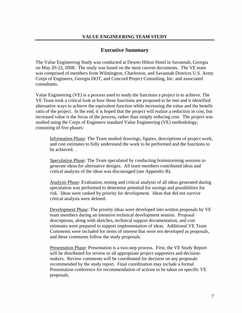
VALUE ENGINEERING TEAM STUDY
Executive Summary
The Value Engineering Study was conducted at Desoto Hilton Hotel in Savannah, Georgia on May 20-22, 2008. The study was based on the most current documents. The VE team was comprised of members from Wilmington, Charleston, and Savannah Districts U.S. Army Corps of Engineers, Georgia DOT, and Concord Project Consulting, Inc. and associated consultants. Value Engineering (VE) is a process used to study the functions a project is to achieve. The VE Team took a critical look at how these functions are proposed to be met and it identified alternative ways to achieve the equivalent function while increasing the value and the benefit ratio of the project. In the end, it is hoped that the project will realize a reduction in cost, but increased value is the focus of the process, rather than simply reducing cost. The project was studied using the Corps of Engineers standard Value Engineering (VE) methodology, consisting of five phases:
Information Phase: The Team studied drawings, figures, descriptions of project work, and cost estimates to fully understand the work to be performed and the functions to be achieved. .
Speculation Phase: The Team speculated by conducting brainstorming sessions to generate ideas for alternative designs. All team members contributed ideas and critical analysis of the ideas was discouraged (see Appendix B). Analysis Phase: Evaluation, testing and critical analysis of all ideas generated during speculation was performed to determine potential for savings and possibilities for risk. Ideas were ranked by priority for development. Ideas that did not survive critical analysis were deleted. Development Phase: The priority ideas were developed into written proposals by VE team members during an intensive technical development session. Proposal descriptions, along with sketches, technical support documentation, and cost estimates were prepared to support implementation of ideas. Additional VE Team Comments were included for items of interest that were not developed as proposals, and these comments follow the study proposals.
Presentation Phase: Presentation is a two-step process. First, the VE Study Report will be distributed for review to all appropriate project supporters and decision-makers. Review comments will be coordinated for decision on any proposals recommended by the study report. Final coordination may include a formal Presentation conference for recommendation of actions to be taken on specific VE proposals.
8
VALUE ENGINEERING TEAM STUDY
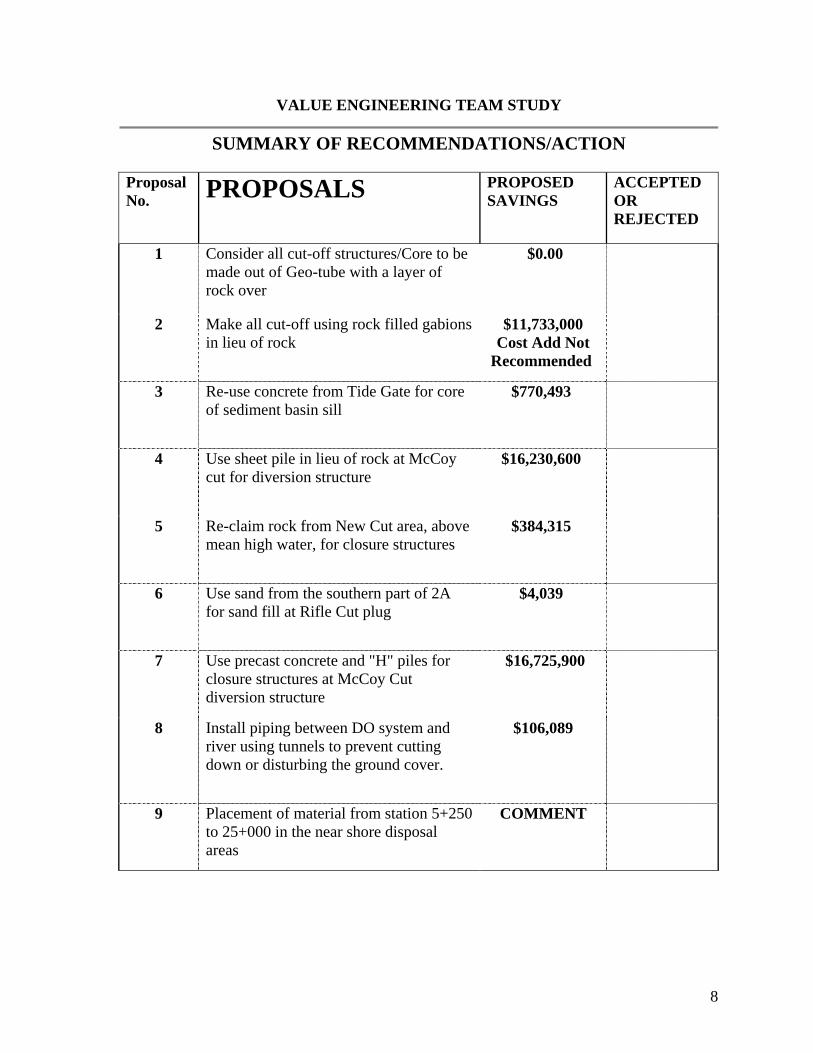
SUMMARY OF RECOMMENDATIONS/ACTION Proposal No. PROPOSALS PROPOSED
SAVINGS ACCEPTED OR REJECTED
1 Consider all cut-off structures/Core to be made out of Geo-tube with a layer of rock over
$0.00
2 Make all cut-off using rock filled gabions in lieu of rock
$11,733,000 Cost Add Not
Recommended
3 Re-use concrete from Tide Gate for core of sediment basin sill
$770,493
4 Use sheet pile in lieu of rock at McCoy cut for diversion structure
$16,230,600
5 Re-claim rock from New Cut area, above mean high water, for closure structures
$384,315
6 Use sand from the southern part of 2A for sand fill at Rifle Cut plug
$4,039
7 Use precast concrete and "H" piles for closure structures at McCoy Cut diversion structure
$16,725,900
8 Install piping between DO system and river using tunnels to prevent cutting down or disturbing the ground cover.
$106,089
9 Placement of material from station 5+250 to 25+000 in the near shore disposal areas
COMMENT

9
10 Allow clamshell dredging in all dredging areas of this project outside the naturally enriched Cadmium zones and off shore disposal (for dredging during fish window)
COMMENT
11 Use Military personnel labor for cleaning/clearing Bear Creek
COMMENT
12 Utilize pontoon track vehicle for clearing Bear Creek
COMMENT
13 Verify that the cost in the estimate for removing the CSS Georgia is correctly identified (shows correct cost)
COMMENT
14 Verify the cost in the estimate for removal of debris is correct
COMMENT
15 Allow dredging by clam shell during fish windows outside the naturally enriched Cadmium zones and off shore disposal (for dredging during fish window)
COMMENT
16 Consider requesting that fish windows are extended or lifted
COMMENT
17 Lower elevation of the DO system to reduce added hydraulic related costs
COMMENT
18 Verify required buffer zone width for DO system
COMMENT
19 Determine if the number of pipes between the DO system (generators) and the river by combining inlet and/or outfalls and be reduced
COMMENT

10
20 Use available sand materials from Tide Gate abutments to fill Geo--tubes
COMMENT
21 Allow the use of Geo--bags to build plugs in lieu of Geo--tubes
COMMENT
22 Allow the dredge materials from upstream mitigation areas to be used to build up the USFWS dikes
COMMENT
23 Consider as part of the mitigation, pumping the dredge material to the underside of the marsh mat
COMMENT
24 Consider reducing the width of the outer bar channel from 600' to 500' in width
COMMENT
25 Consider deepening only 500' wide in lieu of 600' wide bottom in outer bar channel using a step arrangement
COMMENT

11
VALUE ENGINEERING PROPOSAL PROPOSAL NO: 1 PAGE NO: 1 OF 2 DESCRIPTION: Consider all cut-off structures/core to be made out of Geo--tube with a layer of rock over. ORIGINAL DESIGN: Closure structures for McCoy’s Cut (western branch), Rifle Cut and the Sediment Basin sill were constructed of GADOT Type 1 riprap. PROPOSED DESIGN: Construct closure structures with a Geo--tube core and outer layer of rock ADVANTAGES: • Possible Cost Savings • Possible use of dredged material from McCoys Cut for filling • Easier removal if project does not successfully achieve environmental goals (adaptive
management) DISADVANTAGES: Increased maintenance Difficulty in in-water placement Possible damage from floating debris JUSTIFICATION/ADDITIONAL NOTES: This alternative was evaluated based on information included in U.S. Army Corps of Engineer Publication ERDC/CHL CHETN-II-50, entitled Geo-textile Tube Structures, Guidelines for Contract Specifications, September 2006, and WRP Technical Note HS-RS-3.2, entitled Geo--textile Tube Structures for Wetlands Restoration and Protection, January 1998. Based on these publications, the best case for use of these tubes is in a shallow water (0-3 feet), low tidal range(0-3 feet), low wave energy environment. Although the wave energy is low at the proposed placement locations, currents are strong in these areas and accurate placement would be difficult. The existing depth at McCoy’s and Rifle cut is approximately 12 feet below mean lower low water at McCoy’s and Rifle Cuts and up to 40 feet below mean lower low water at the Sediment Basin. In addition, the tidal range is over 7 feet in the Savannah area. This project does not meet the criteria required for Geo--textile Tube Applications. Further development of this proposal is not recommended.
12
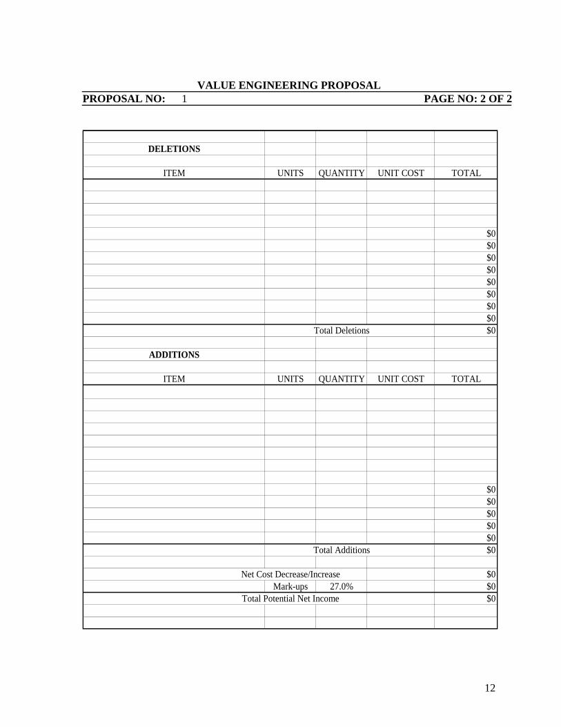
VALUE ENGINEERING PROPOSAL
PROPOSAL NO: 1 PAGE NO: 2 OF 2
DELETIONS
ITEM UNITS QUANTITY UNIT COST TOTAL
$0$0$0$0$0$0$0
$0Total Deletions $0
ADDITIONS
ITEM UNITS QUANTITY UNIT COST TOTAL
$0$0
$0$0
$0Total Additions $0
Net Cost Decrease/Increase $0Mark-ups 27.0% $0
Total Potential Net Income $0
13
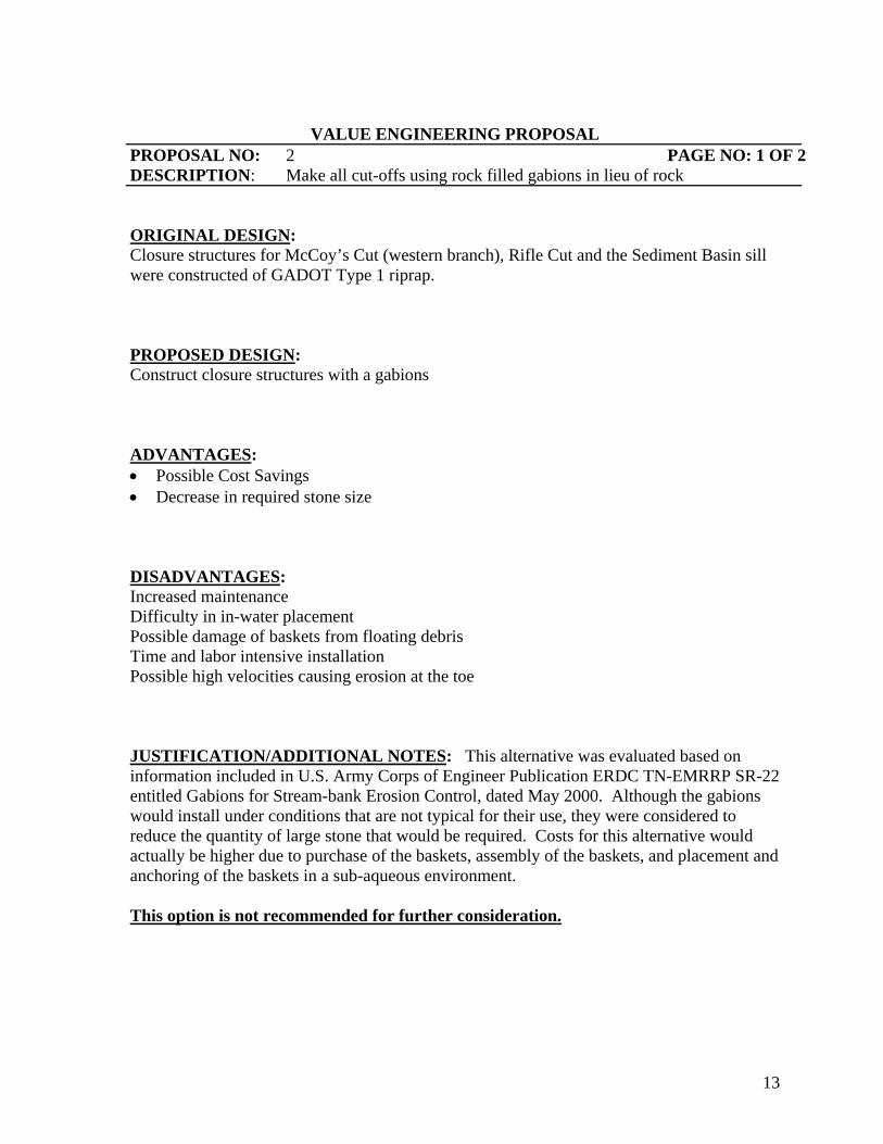
VALUE ENGINEERING PROPOSAL
PROPOSAL NO: 2 PAGE NO: 1 OF 2 DESCRIPTION: Make all cut-offs using rock filled gabions in lieu of rock ORIGINAL DESIGN: Closure structures for McCoy’s Cut (western branch), Rifle Cut and the Sediment Basin sill were constructed of GADOT Type 1 riprap. PROPOSED DESIGN: Construct closure structures with a gabions ADVANTAGES: • Possible Cost Savings • Decrease in required stone size DISADVANTAGES: Increased maintenance Difficulty in in-water placement Possible damage of baskets from floating debris Time and labor intensive installation Possible high velocities causing erosion at the toe JUSTIFICATION/ADDITIONAL NOTES: This alternative was evaluated based on information included in U.S. Army Corps of Engineer Publication ERDC TN-EMRRP SR-22 entitled Gabions for Stream-bank Erosion Control, dated May 2000. Although the gabions would install under conditions that are not typical for their use, they were considered to reduce the quantity of large stone that would be required. Costs for this alternative would actually be higher due to purchase of the baskets, assembly of the baskets, and placement and anchoring of the baskets in a sub-aqueous environment. This option is not recommended for further consideration.
14
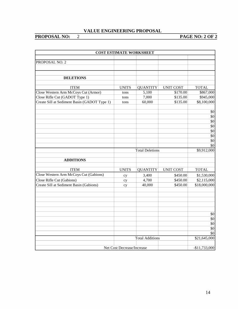
VALUE ENGINEERING PROPOSAL PROPOSAL NO: 2 PAGE NO: 2 OF 2
PROPOSAL NO. 2
DELETIONS
ITEM UNITS QUANTITY UNIT COST TOTALClose Western Arm McCoys Cut (Armor) tons 5,100 $170.00 $867,000Close Rifle Cut (GADOT Type 1) tons 7,000 $135.00 $945,000Create Sill at Sediment Basin (GADOT Type 1) tons 60,000 $135.00 $8,100,000
$0$0$0$0$0$0$0
$0Total Deletions $9,912,000
ADDITIONS
ITEM UNITS QUANTITY UNIT COST TOTALcy 3,400 $450.00 $1,530,000
Close Rifle Cut (Gabions) cy 4,700 $450.00 $2,115,000Create Sill at Sediment Basin (Gabions) cy 40,000 $450.00 $18,000,000
$0$0
$0$0
$0Total Additions $21,645,000
Net Cost Decrease/Increase -$11,733,000
COST ESTIMATE WORKSHEET
Close Western Arm McCoys Cut (Gabions)
15
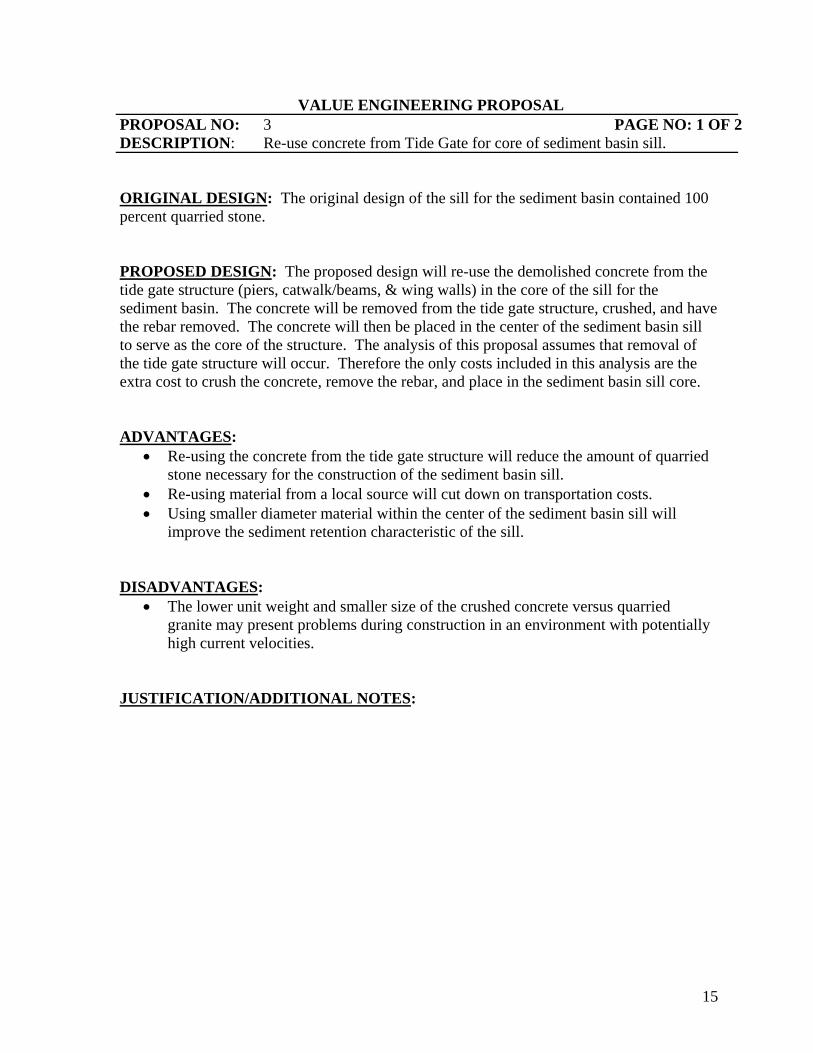
VALUE ENGINEERING PROPOSAL PROPOSAL NO: 3 PAGE NO: 1 OF 2 DESCRIPTION: Re-use concrete from Tide Gate for core of sediment basin sill. ORIGINAL DESIGN: The original design of the sill for the sediment basin contained 100 percent quarried stone. PROPOSED DESIGN: The proposed design will re-use the demolished concrete from the tide gate structure (piers, catwalk/beams, & wing walls) in the core of the sill for the sediment basin. The concrete will be removed from the tide gate structure, crushed, and have the rebar removed. The concrete will then be placed in the center of the sediment basin sill to serve as the core of the structure. The analysis of this proposal assumes that removal of the tide gate structure will occur. Therefore the only costs included in this analysis are the extra cost to crush the concrete, remove the rebar, and place in the sediment basin sill core. ADVANTAGES:
• Re-using the concrete from the tide gate structure will reduce the amount of quarried stone necessary for the construction of the sediment basin sill.
• Re-using material from a local source will cut down on transportation costs. • Using smaller diameter material within the center of the sediment basin sill will
improve the sediment retention characteristic of the sill. DISADVANTAGES:
• The lower unit weight and smaller size of the crushed concrete versus quarried granite may present problems during construction in an environment with potentially high current velocities.
JUSTIFICATION/ADDITIONAL NOTES:

16
VALUE ENGINEERING PROPOSAL PROPOSAL NO: 3 PAGE NO: 2 OF 2
PROPOSAL NO. 3Re-use concrete from Tide Gate for core of sediment basin sill.
DELETIONS
ITEM UNITS QUANTITY UNIT COST TOTALType 1 GaDOT Stone Tons 4,875 $135.00 $658,125
$0$0$0$0$0$0$0$0$0$0
$0Total Deletions $658,125
ADDITIONS
ITEM UNITS QUANTITY UNIT COST TOTALCrushed and sorted concrete debris Tons 4,875 $8.50 $41,438Mob & demob 1 $10,000.00 $10,000
$0$0
$0 $0
$0 $0
$0 $0
Total Additions $51,438
Net Cost Decrease/Increase $606,688Mark-ups 27.0% $163,806
Total Potential Net Income $770,493
COST ESTIMATE WORKSHEET
17
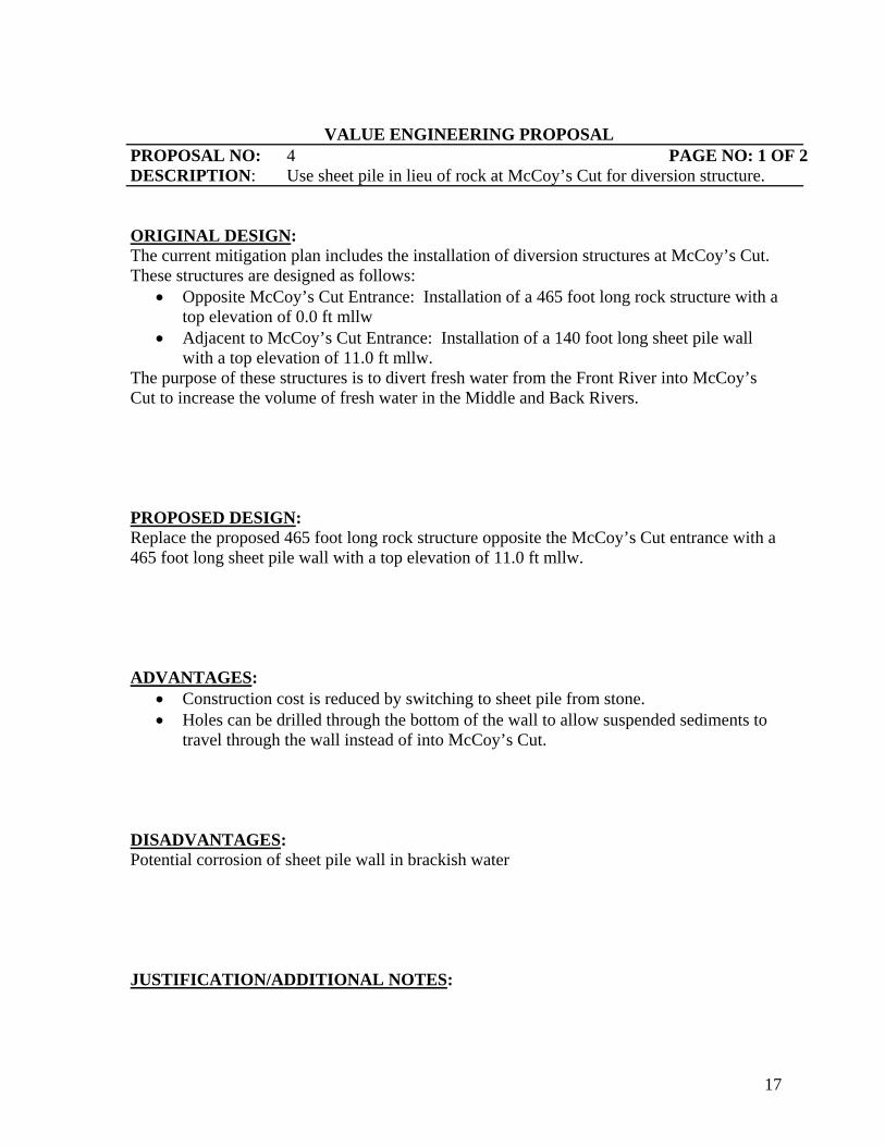
VALUE ENGINEERING PROPOSAL PROPOSAL NO: 4 PAGE NO: 1 OF 2 DESCRIPTION: Use sheet pile in lieu of rock at McCoy’s Cut for diversion structure. ORIGINAL DESIGN: The current mitigation plan includes the installation of diversion structures at McCoy’s Cut. These structures are designed as follows:
• Opposite McCoy’s Cut Entrance: Installation of a 465 foot long rock structure with a top elevation of 0.0 ft mllw
• Adjacent to McCoy’s Cut Entrance: Installation of a 140 foot long sheet pile wall with a top elevation of 11.0 ft mllw.
The purpose of these structures is to divert fresh water from the Front River into McCoy’s Cut to increase the volume of fresh water in the Middle and Back Rivers. PROPOSED DESIGN: Replace the proposed 465 foot long rock structure opposite the McCoy’s Cut entrance with a 465 foot long sheet pile wall with a top elevation of 11.0 ft mllw. ADVANTAGES:
• Construction cost is reduced by switching to sheet pile from stone. • Holes can be drilled through the bottom of the wall to allow suspended sediments to
travel through the wall instead of into McCoy’s Cut. DISADVANTAGES: Potential corrosion of sheet pile wall in brackish water JUSTIFICATION/ADDITIONAL NOTES:

18
VALUE ENGINEERING PROPOSAL PROPOSAL NO: 4 PAGE NO: 2 OF 2
PROPOSAL NO. 4Use sheet pile in lieu of rock at McCoys Cut for diversion structure.
DELETIONS
ITEM UNITS QUANTITY UNIT COST TOTALDiversion structure at entrance to McCoys tons 81,000 $175.00 $14,175,000 Cut - stone $0
$0$0$0$0$0$0$0$0$0
$0Total Deletions $14,175,000
ADDITIONS
ITEM UNITS QUANTITY UNIT COST TOTAL
Sheet pile LF 465 $3,000.00 $1,395,000$0$0$0
$0 $0
$0 $0
$0 $0
Total Additions $1,395,000
Net Cost Decrease/Increase $12,780,000Mark-ups 27.0% $3,450,600
Total Potential Net Income $16,230,600
COST ESTIMATE WORKSHEET
Diversion wall at entrance to McCoys Cut
19
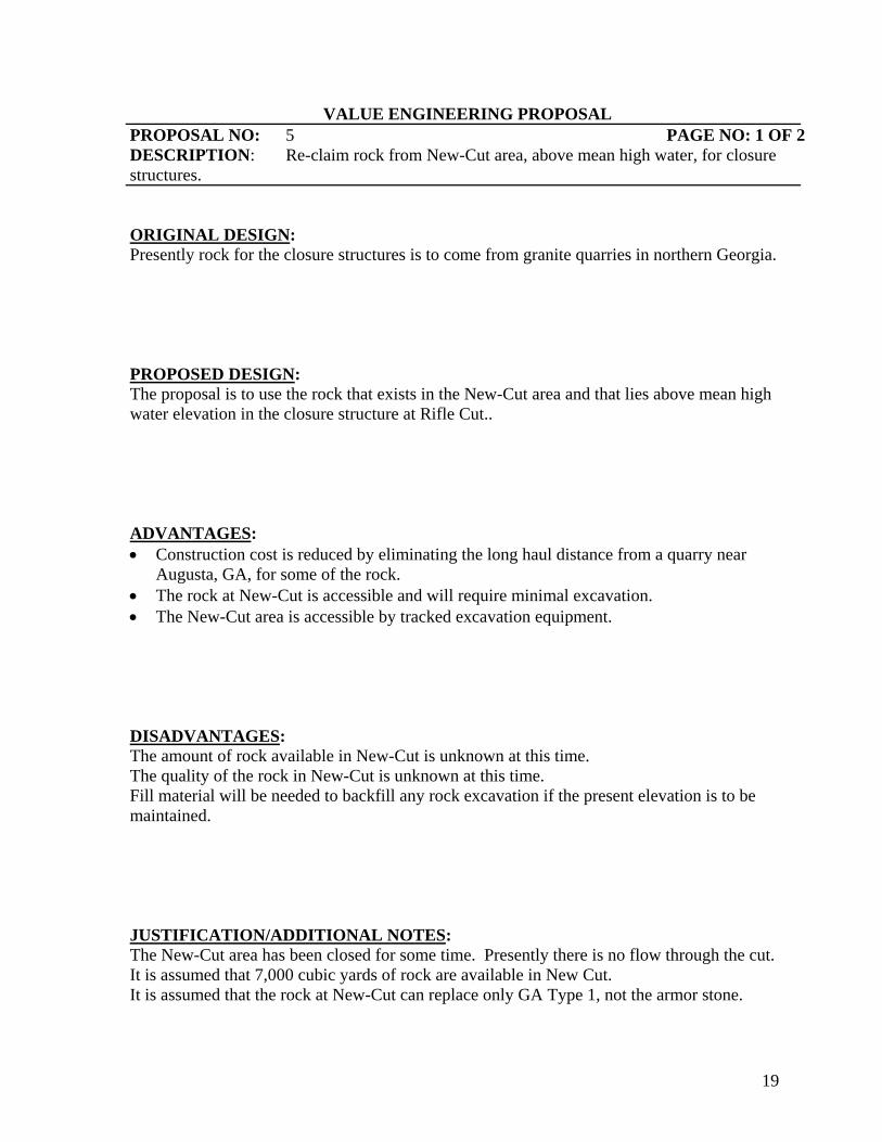
VALUE ENGINEERING PROPOSAL PROPOSAL NO: 5 PAGE NO: 1 OF 2 DESCRIPTION: Re-claim rock from New-Cut area, above mean high water, for closure structures. ORIGINAL DESIGN: Presently rock for the closure structures is to come from granite quarries in northern Georgia. PROPOSED DESIGN: The proposal is to use the rock that exists in the New-Cut area and that lies above mean high water elevation in the closure structure at Rifle Cut.. ADVANTAGES: • Construction cost is reduced by eliminating the long haul distance from a quarry near
Augusta, GA, for some of the rock. • The rock at New-Cut is accessible and will require minimal excavation. • The New-Cut area is accessible by tracked excavation equipment. DISADVANTAGES: The amount of rock available in New-Cut is unknown at this time. The quality of the rock in New-Cut is unknown at this time. Fill material will be needed to backfill any rock excavation if the present elevation is to be maintained. JUSTIFICATION/ADDITIONAL NOTES: The New-Cut area has been closed for some time. Presently there is no flow through the cut. It is assumed that 7,000 cubic yards of rock are available in New Cut. It is assumed that the rock at New-Cut can replace only GA Type 1, not the armor stone.

20
VALUE ENGINEERING PROPOSAL PROPOSAL NO: 5 PAGE NO: 2 OF 2
PROPOSAL NO. 5Re-claim rock from New-Cut area, above mean high water, for closure structures.
DELETIONS
ITEM UNITS QUANTITY UNIT COST TOTALRock from quarry - Ga DOT - type 1. tons 7,000 $135.00 $945,000
$0$0$0$0$0$0$0$0$0$0
$0Total Deletions $945,000
ADDITIONS
ITEM UNITS QUANTITY UNIT COST TOTAL
Rock excavated from New Cut area. tons 7,000 $91.77 $642,390$0$0$0
$0 $0
$0 $0
$0 $0
Total Additions $642,390
Net Cost Decrease/Increase $302,610Mark-ups 27.0% $81,705
Total Potential Net Income $384,315
COST ESTIMATE WORKSHEET

21
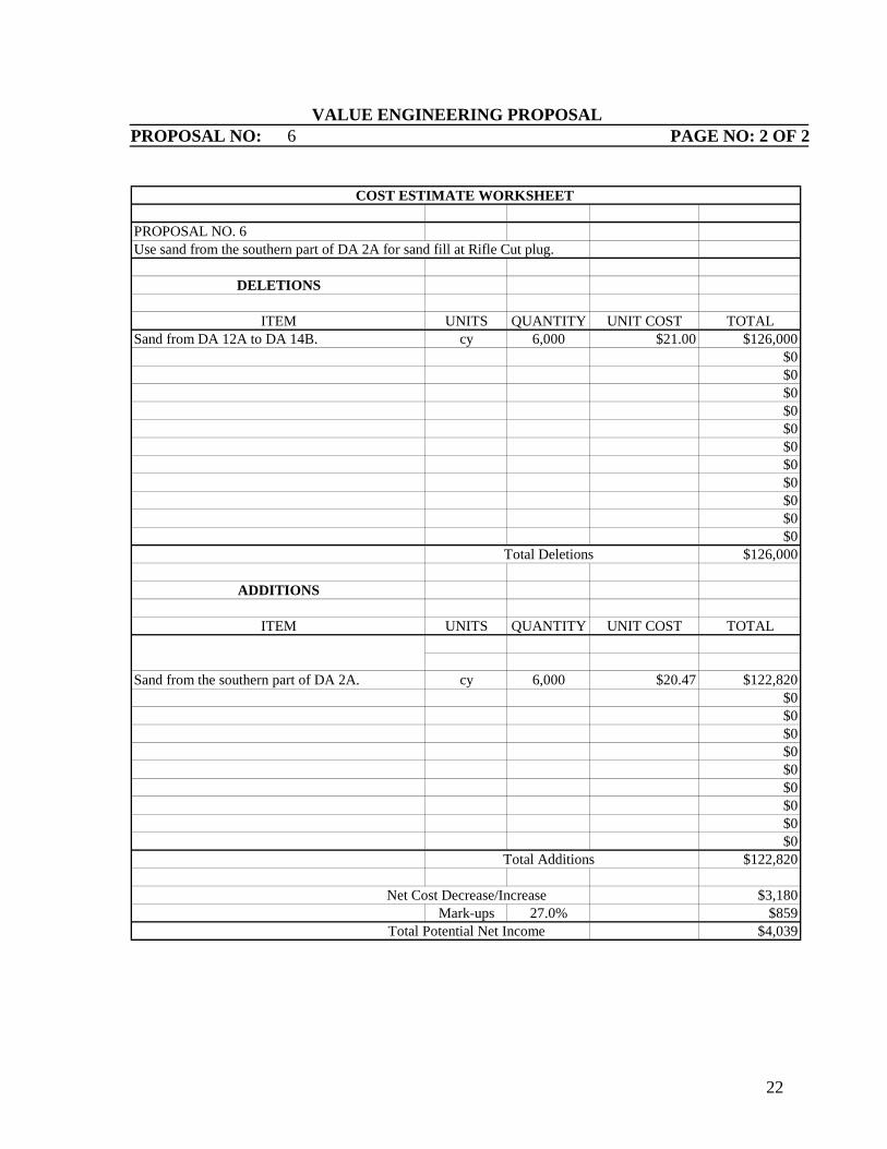
VALUE ENGINEERING PROPOSAL PROPOSAL NO: 6 PAGE NO: 1 OF 2 DESCRIPTION: Use sand from the southern part of DA 2A for sand fill at Rifle Cut plug. ORIGINAL DESIGN: Presently sand for the rock plug at Rifle Cut is to come from disposal areas 12A to 14B. PROPOSED DESIGN: The proposal is to use the sand that exists in disposal area 2A (DA 2A) that lies in about southern part of the disposal area. ADVANTAGES: • Construction cost is reduced by shortening the haul distance for sand. • The sand in DA 2A is accessible and will require minimal excavation. • The DA 2A sand is accessible by tracked excavation equipment. • Excavation of sand in DA 2A would increase the available capacity there if needed. DISADVANTAGES: The amount of sand available in DA 2A is unknown at this time. The quality of the sand in DA 2A is unknown at this time. JUSTIFICATION/ADDITIONAL NOTES: The material could be excavated and hauled to the northern end of the area which is nearest to Rifle Cut. The material would then be barged from there to Rifle Cut. It is assumed that
enough suitable sand is available in DA 2A.
22
VALUE ENGINEERING PROPOSAL PROPOSAL NO: 6 PAGE NO: 2 OF 2
PROPOSAL NO. 6Use sand from the southern part of DA 2A for sand fill at Rifle Cut plug.
DELETIONS
ITEM UNITS QUANTITY UNIT COST TOTALSand from DA 12A to DA 14B. cy 6,000 $21.00 $126,000
$0$0$0$0$0$0$0$0$0$0
$0Total Deletions $126,000
ADDITIONS
ITEM UNITS QUANTITY UNIT COST TOTAL
Sand from the southern part of DA 2A. cy 6,000 $20.47 $122,820 $0 $0
$0 $0 $0
$0 $0
$0 $0
Total Additions $122,820
Net Cost Decrease/Increase $3,180Mark-ups 27.0% $859
Total Potential Net Income $4,039
COST ESTIMATE WORKSHEET
23
VALUE ENGINEERING PROPOSAL PROPOSAL NO: 7 PAGE NO: 1 OF 2 DESCRIPTION: Use precast concrete and “H” piles for diversion structure at McCoy’s Cut ORIGINAL DESIGN: The current mitigation plan includes the installation of diversion structures at McCoy’s Cut. These structures are designed as follows:
• Opposite McCoy’s Cut Entrance: Installation of a 465 foot long rock structure with a top elevation of 0.0 ft mllw
• Adjacent to McCoy’s Cut Entrance: Installation of a 140 foot long sheet pile wall with a top elevation of 11.0 ft mllw.
The purpose of these structures is to divert fresh water from the Front River into McCoy’s Cut to increase the volume of fresh water in the Middle and Back Rivers. PROPOSED DESIGN: Replace the proposed 465 foot long rock structure opposite the McCoy’s Cut entrance with a 465 foot long precast concrete wall held in place by “H” piles driven into the river bottom with a top elevation of 11.0 ft mllw. ADVANTAGES:
• Construction cost is reduced by switching to a precast concrete wall from stone. • Adaptive Management would be easier as panels could be removed and reused if the
wall needs to be adjusted. • Spacers can be placed at the bottom of the wall to allow suspended sediments to
travel under the wall instead of into McCoy’s Cut. DISADVANTAGES:
• Corrosion of “H” piles in brackish water. • Settlement of concrete panels into river bottom.
JUSTIFICATION/ADDITIONAL NOTES:
24
VALUE ENGINEERING PROPOSAL PROPOSAL NO: 7 PAGE NO: 2 OF 2
PROPOSAL NO. 7Use precast concrete and “H” piles for diversion structure at McCoy's Cut
DELETIONS
ITEM UNITS QUANTITY UNIT COST TOTALDiversion structure at entrance to McCoy's tons 81,000 $175.00 $14,175,000 Cut - stone $0
$0$0$0$0$0$0$0$0$0
$0Total Deletions $14,175,000
ADDITIONS
ITEM UNITS QUANTITY UNIT COST TOTAL
"H" piles @ 3 ft OC LF 4,000 $100.00 $400,000 Precast Concrete Panels SF 6,050 $100.00 $605,000
$0$0
$0 $0
$0 $0
$0 $0
Total Additions $1,005,000
Net Cost Decrease/Increase $13,170,000Mark-ups 27.0% $3,555,900
Total Potential Net Income $16,725,900
COST ESTIMATE WORKSHEET
Diversion wall at entrance to McCoy's Cut
25
VALUE ENGINEERING PROPOSAL PROPOSAL NO: 8 PAGE NO: 1 OF 2 DESCRIPTION: Install piping between DO system at Mulberry Grove and river using tunnels to prevent cutting down or disturbing the ground cover. ORIGINAL DESIGN: Original plan is to construct piping systems between the river and an upland site located 100 feet or more away to allow for a wooded buffer zone. To reasonably construct this will require an extensive clearing effort which will literally destroy the approved buffer zone. PROPOSED DESIGN: Proposed design is to use directional boring or tunneling techniques to install 20” diameter HDPE piping in-lieu of the 20” diameter DIP being placed in open cut and cover trenches across the environmental buffer zone. ADVANTAGES: • Construction cost is slightly reduced by eliminating a majority of the 20” diameter
Ductile Iron Piping. • Eliminates the destruction and re-establishment of the environmental habit buffer zone
area. • Less corrosion and maintenance of HDPE vs. DIP DISADVANTAGES: There are no foreseen disadvantages with this solution. JUSTIFICATION/ADDITIONAL NOTES:
26
VALUE ENGINEERING PROPOSAL PROPOSAL NO: 8 PAGE NO: 2 OF 2
PROPOSAL NO. 8Install piping between DO system and river using tunnels to prevent disturbing the ground cover.
DELETIONS
ITEM UNITS QUANTITY UNIT COST TOTALClearing and grubbing acres 0.7 $10,000.00 $7,000Rough grade site sf 30,492.0 $2.00 $60,98420" dia bell end DIP (48 runs x say 125') lf 6,000 $220.00 $1,320,000Trench dewatering days 40 $150.00 $6,000Re-establishment of buffer vegetation acres 0.7 $10,000.00 $7,000
$0$0$0$0$0$0
$0Total Deletions $1,400,984
ADDITIONS
ITEM UNITS QUANTITY UNIT COST TOTAL20" dia HDPE (quote Egan Bro's 843-709-2455) lf 6,000 $220.00 $1,320,000
$0$0$0
$0 $0
$0 $0
$0 $0
Total Additions $1,320,000
Net Cost Decrease/Increase $80,984Mark-ups 31.0% $25,105
Total Potential Net Income $106,089
COST ESTIMATE WORKSHEET
27
VALUE ENGINEERING COMMENTS
Comment No. 9 Placement of material from Sta 5+250 to 25+000 in the near shore disposal areas: The material from this reach is scheduled to be placed in confined upland disposal sites along the Savannah River. This is the most economical way for disposal. With upland sites being depleted, consideration should be given to the option of utilizing the near shore disposal areas. Current cost of upland use is say $4.00/cy and to put it in the near shore areas is say $6.50/cy. There are additional costs associated with upland placement such as dike maintenance while there is none associated with the near shore sites. Consideration should be closely monitored or even be offered as option bid items in future contracts to see if this will offset any anticipated disposal utilization fees. Comment No. 10 Allow clamshell dredging in all dredging areas of this project outside the naturally enriched Cadmium zones and offshore disposal (for dredging during fish window): By making clamshell dredging available to the contractor in all areas of the project outside the zone containing naturally enriched Cadmium, the project would potentially benefit by being able to operate during the fish window. Being able to operate during the fish window would reduce the number of mobilizations and demobilizations required by the contractor. Depending on production rates between the different available dredging techniques, clamshell dredging may reduce the project costs and the overall construction duration. Comment No. 11 Use Military personnel labor for cleaning/clearing Bear Creek: The environment around Bear Creek is very remote and difficult to access using heavy construction equipment. Removal of fallen trees and snags from this area which are blocking freshwater flows will be a difficult and labor intensive task. In the past, there have been occasions when the military has taken it upon itself to accept the challenge of such a Civil Works project and use it as a training project. Although, at the present time, are armed forces are taxed by lengthy deployments, this could be considered a training opportunity if the manpower is available and willing at the time the project is constructed. Comment No. 12 Utilize Amphibian Pontoon Tracked Excavators for clearing Bear Creek: This equipment has been demonstrated in the Charleston District as the most efficient and economical method for clearing and snagging of highly dense vegetation from shallow, swampy nearly undefined channels. This equipment is currently being used to clean out an old, almost nearly undefined channel of old hurricane debris which has devastated the Pocotaligo Swamp. The equipment can operate without the aid of mats and can remove and lift very large cypress trees out of the way. The equipment can completely float so will not require barging as long as the boom can reach the bottom. The machine will have to make its path wide enough to get through the area a minimum of 18 feet. (width of machine). The purpose of the Pocotaligo Project was to open out old channels to obtain previous natural flows and to also allow access to areas where small boats could perform aquatic weed spraying and the replanting of cypress trees which had fallen during the hurricane. Production rates for this equipment varies depending on density of debris but has averaged over 100 feet per hour in fairly dense swampy remote conditions at a cost of around $350/hr. Costs are only $275/hr if it can be accessed by land and is not remote.

28
Comment No. 13 Verify costs for removing the CSS Georgia: The costs for performing the removal and preservation requirements were provided by Judy Wood (SAM-PD-EI) and should be investigated to insure that reasonable costs and procedures are used. There is potential for VE savings on the performance of this project task but will require a specialized team familiar with archeological salvage and preservation coupled with innovative marine engineers to reasonable identify potentials. Comment No. 14 Verify costs for performing the removal of debris: The costs for performing the removal of debris were provided by others based on old historical construction techniques, quantities and costs from the last deepening project. There is potential for VE savings on the performance of this project task. Investigations should be made to insure that efficient construction techniques will be used to fully capture any potential cost savings. Comment No. 15 Allow dredging by clamshell during fish windows outside the naturally enriched Cadmium zones and offshore disposal (for dredging during fish window): By making clamshell dredging available to the contractor in all areas of the project outside the zone containing naturally enriched Cadmium, the project would potentially benefit by being able to operate during the fish window. Being able to operate during the fish window would reduce the number of mobilizations and demobilizations required by the contractor. Depending on production rates between the different available dredging techniques, clamshell dredging may reduce the project costs and the overall construction duration. Comment No.16 Consider requesting that fish windows are extended or lifted: There are many mobilization and demobilization costs included in the estimate. This is partly due to the starting and stopping of work because of the fish windows and this increases the cost significantly. If the fish windows could be lifted or the work period extended some of the costs may be reduced, since this would reduce the stoppages and allow for more work time. Comment No. 17 Lower elevation of the DO system to reduce added hydraulic related costs: By lowering the submerged portion of the dissolved oxygen system within the water column, the project could take advantage of the head/pressure differences to reduce the amount of energy required to pump the oxygen saturated water back into the river. Comment No. 18 Verify required buffer zone width for the DO system at Mulberry Grove: The plan shows that a buffer zone of 100 feet be maintained between the river and the Speece Cone OD equipment. This buffer zone adds a great deal of cost to the project and could be alleviated if reduced or eliminated entirely. Criteria should be investigated to check validity since there are similar commercial and industrial plants already in the nearby area that produce similar impacts and are allowed without buffers. Comment No. 19 Determine if the number of pipes can be reduced between the DO systems and the river by utilizing larger diameter pipes or conduits to combine inlets and outlets: The current design uses separate inlet and outlet 20” diameter ductile iron pipes running from each of the Speece Cone OD units to the water source. Investigations should be made to verify that a more cost effective system could be designed when there are several of these units

29
being constructed in close proximity to each other. It is believed that at a minimum, the intake portion could be redesigned to take advantage of using less but larger intake pipes. Comment No. 20 Use available sand materials from the Tide Gate abutments to fill Geo--tubes, Containers or Bags: Materials removed from the abutments provide for a great source which could be used for filling Geo-textile containment products. Also noted in this area is the large quantity of rip rap that will be removed. This quantity of rip rap should be considered as valuable salvage and used for other aspects of this project. Comment No. 21 Allow the use of Geo-bags to build plugs and diversion structures throughout the project where Geo-tubes or rock is used: Geo-bags could be used in-lieu of Geo-tubes should the installation of the tubes become prohibitive. The cost for the smaller containments of 10 cubic yards will cost say $500 each as compared to 250 cubic yards in a tube at $2500 each. $50/CY vs. $10/CY. This is still a tremendous savings over rip rap which is pricing out around $200/cy due to the high cost of trucking from distant quarry locations. This is assuming the fill for the Geo-textile products are free and readily available nearby. Also noted that the design slopes of 3 to 1 have the potential of being steepened to 2.5 to say 1.5 to 1 if constructed effectively thereby reducing the preliminary estimated quantities for all these materials being ultimately used in the project. Comment No. 22 Allow the dredged materials from upstream mitigation areas to be used to build up the USFWS dikes: The project plan is to dredge 463,000 C.Y. of material from freshwater areas upstream of the project to increase freshwater flows into the Savannah National Wildlife Refuge. Presently the assumption is that the material will be pumped into scows, carried downstream to the harbor disposal areas, and pumped out of the scows. This is an excessively costly method of disposal. The existing dikes within the refuge are in bad conditions in many locations. If the Fish and Wildlife Service agrees, the material from these creeks could be used to help rebuild their dikes while reducing disposal costs. Due to the sensitive nature of the refuge, the full concurrence of the Fish and Wildlife Service would be required. Also, it is likely that additional testing of the material would be required during the engineering phase of the contract to establish the gradation of the material as well as the possible presence of contaminants. Comment No. 23 Consider as part of the mitigation, pumping the dredged material to the underside of the marsh mat: The marshes within the wildlife refuge and the adjacent areas are decreasing in elevation due to the combined effect of subsidence and sea level rise. Although it is a novel idea, one possible way to offset this decrease would to pump the dredged material below the marsh mat in these areas. Once again, extensive coordination with the resource agencies would be required as well as material testing. However, this method could potentially provide both an environmental benefit as well as a cost savings to the project. Comment No.24 Consider reducing the width of the outer bar channel from 600 feet to 500 feet: The present channel bottom design is 600 feet wide. If the channel bottom width is reduced to 500 feet, the amount of dredge material in both the channel bottom and side slopes, and the time for the work should be reduced. The Environmental agencies may find this agreeable and there should be negligible effect on shipping.

30
Comment No. 25 Consider deepening only 500 feet wide in lieu of 600 feet wide bottom in the outer bar channel using a step arrangement: The present design is a 600 foot wide channel bottom on the outer bar. A 500 foot wide channel bottom with a 100 foot step should be considered. This would provide for less dredge material to be disposed and also provide some advanced maintenance. The 100 foot step would trap material sloughing from the side slope thus providing the advance maintenance feature. The reduction in channel width should have negligible effect on shipping.
31
APPENDIX A:
CONTACT DIRECTORY

32
VALUE ENGINEERING STUDY ATTENDEE SHEET SIGN-IN SHEET May 20-22, 2008
PROJECT DESCRIPTION: VES 08-21 Expansion of Savannah Harbor P2 113006 TIME: 0830 PLACE: Savannah, Georgia (Hilton Desoto Madison Conference Room)
NAME: POSITION: ORGANIZATION Email address and Telephone: Tommy Blewett
Facilitator/ Team Leader
John T. Blewett, PE Consulting Engineers
[email protected] 912-754-7445
Tom Child
Geo-tech
SAW
[email protected] 910-251-4708
Brian Williams
Geo-tech/ Marine Construction
SAC
[email protected] 912-652-5188
Jim Henderson
Dredging/Cost Engineer
SAC
[email protected] 843-329-8141
David Griffin
Civil/ Structures
GA DOT
[email protected] 404-631-1228
Carol Abercrombie
Coastal Engineer
SAS
[email protected] 912-652-5514
Alan Garrett
Project Manager
SAS
[email protected] 912-652-5172
Hope Moorer
Program Manager
GPS (Georgia Ports Authority)
[email protected] 912-964-3883
Joe Hoke
Hydraulic Engineer
USACE SAW/SAS
[email protected] 912-652-5516
Joe Hudak
Civil Engineer
USACE
[email protected] 912-6652-5681
Jamie Measmer
Electrical Engineer
USACE

33
Craig N. Wiederhold
Plan Formulator
USACE SAM/SAS
[email protected] 912-484-8283
Larry Keegan
PM for GPA
CH2M Hill
[email protected] 912-330-3025
Wilbur Wiggins
Civil Engineer
USACE
[email protected] 912-652-5542

34
APPENDIX B:
SPECULATION LIST

35
SPECULATION LIST Y, N, C, BD
Proposal No. PROPOSALS
Y 1 Consider all cut-off structures/Core to be made out of Geo-tube with a layer of rock over
Y 2 Make all cut-off using rock filled gabions in lieu of rock
Y 3 Re-use concrete from Tide Gate for core of sediment basin sill
Y 4 Use sheet pile in lieu of rock at McCoy cut for diversion structure
Y 5 Re-claim rock from New Cut area, above mean high water, for closure structures
Y 6 Use sand from the southern part of 2A for sand fill at Rifle Cut plug
Y 7 Use precast concrete and "H" piles for closure structures at McCoy Cut diversion structure
Y 8 Install piping between DO system and river using tunnels to prevent cutting down or disturbing the ground cover.
C 9 Placement of material from station 5+250 to 25+000 in the near shore disposal areas
C 10 Allow clamshell dredging in all dredging areas of this project outside the naturally enriched Cadmium zones and off shore disposal (for dredging during fish window)
C 11 Use Military personnel labor for cleaning/clearing Bear Creek
C 12 Utilize pontoon track vehicle for clearing Bear Creek
C 13 Verify that the cost in the estimate for removing the CSS Georgia is correctly identified (shows correct cost)
C 14 Verify the cost in the estimate for removal of debris is correct

36
C 15 Allow dredging by clam shell during fish windows outside the naturally enriched Cadmium zones and off shore disposal (for dredging during fish window)
C 16 Consider requesting that fish windows are extended or lifted
C 17 Lower elevation of the DO system to reduce added hydraulic related costs
C 18 Verify required buffer zone width for DO system
C 19 Determine if the number of pipes between the DO system (generators) and the river by combining inlet and/or outfalls and be reduced
C 20 Use available sand materials from Tide Gate abutments to fill Geo-tubes
C 21 Allow the use of Geo-bags to build plugs in lieu of Geo-tubes
C 22 Allow the dredge materials from upstream mitigation areas to be used to build up the USFWS dikes
C 23 Consider as part of the mitigation, pumping the dredge material to the underside of the marsh mat
C 24 Consider reducing the width of the outer bar channel from 600' to 500' in width
C 25 Consider deepening only 500' wide in lieu of 600' wide bottom in outer bar channel using a step arrangement
N 26 Use alternate disposal site for McCoy cut dredging, McCoy Cut, Little Back River, Middle River
N 27 Replace steel sheet pile with vinyl sheet pile
N 28 Use clamshell to remove the debris and dispose off shore
N 29 Put Cadmium in Steel drums and ship to China
N 30 In developing the contract consider allowing Clam Shell outside the naturally enriched Cadmium zones and off shore disposal (for dredging during fish window)
N 31 Remove Tide Gates but leave in place the abutments and not widen the channel in this area