
Repair Guideline for TCL DC Inverter Air Conditioner · Repair Guideline for TCL DC Inverter Air...
40
Repair Guideline for TCL DC Inverter Air Conditioner
Transcript of Repair Guideline for TCL DC Inverter Air Conditioner · Repair Guideline for TCL DC Inverter Air...

Repair Guideline for TCL DC Inverter Air Conditioner

1
Contents I. Electrical Control of Inverter Air Conditioner ········································································2
1. Main compositions of the electrical control of inverter air conditioner ·······························2 2. Wiring of Inverter AC Unit ································································································3 3. Current Flow ······················································································································4 4. Computer Control Function Flow Chart for Inverter AC Unit ············································5 5. Protection and Fault Codes·································································································5
II. Troubleshooting····················································································································8 1. According to the fault code ································································································8 (1) Display E1 or E2: ·············································································································8 (2) Display E6························································································································9 (3) Display E3, E7, E8 ···········································································································10 (4) Display E4························································································································11 (5) Display EC ·······················································································································13 (6) Display EP························································································································14 (7) Display EA·······················································································································16 (8) Display EU·······················································································································17 (9) Display E9 (Firstly display P0 or P9, then change to E9)··················································18 (10) Display E0、E5··············································································································20 (11) Display EE ·····················································································································22 (12) Display P0 ······················································································································23 (13) Display P1 ······················································································································24 (14) Display P2 ······················································································································24 (15) Display P4 ······················································································································25 (16) Display P5 ······················································································································25 (17) Display P6 ······················································································································26 (18) Display P7 ······················································································································27 (19) Display P8 ······················································································································27 (20) Display P9 ······················································································································28 2. Other faults ························································································································29 1) The indoor unit works normally but the outdoor unit does not work. ·································29 2) The outdoor unit is stopped when the air conditioner has run for a period of time ·············29 3) The air conditioner is tripped when it is started.·································································30 4) The complete unit does not work ·······················································································30
Appendix 1 ································································································································31 Appendix 2 ································································································································34 Appendix 3 ································································································································36 Cautions on Replacement of PCB Boards··················································································37

2
I. Electrical Control of Inverter Air Conditioner
1. Main compositions of the electrical control of inverter air conditioner
The electrical control of inverter air conditioner is divided into indoor control system and outdoor control system.
Relative to the fixed-speed air conditioner, the indoor control system is added with one communication circuit, but removed of the control circuits for compressor, 4-way valve and outdoor fan. The other circuits are basically the same.
The outdoor circuit is generally divided into three parts, i.e. outdoor power source board, Power Factor Correction (PFC) board and Intelligent Power Module (IPM). The details are as follows:
PFC board Outdoor power source board
TCL Inverter Air Conditioner Model 1 – 1.5P has been developed for four generations.
The 1st generation (V1) applies 120° square wave control plan and the all PFC plan is used for power treatment.
The 2nd generation (V2) remains to apply 120° square wave control plan, but the partial PFC plan is used for power treatment. This product is never put into batch production.
The 3rd generation (V3) applies 180° sine wave plan and partial PFC plan. This model is also few.
The 4th generation (V4) remains to apply 180° sine wave plan (including 2P unit), where only significant adjustment is made to the function architecture. That is, the indoor control plan applied for the 1st and 2nd generation is changed to outdoor control (For details on the function distribution, please refer to the Control Function Chart below.
The 5th generation(V5), the function is same as V4, but the Power source board, PFC board and IPM board have already integrated onto one board (All-In-One) for easily installation and
IPM board

3
repairing.
The products 2P and higher are mainly developed for two generations.
The 1st generation (VP1) applies NEC 180° sine wave plan and indoor control.
The 2nd generation (VP2) applies TI DSP 180° sine wave plan and outdoor control. (Exclusive of 2P unit).
There are derivative models, e.g. full DC inverter unit, inverter floor-standing unit and LC plan. See Appendix 1 for details. 2. Wiring of Inverter AC Unit
3. Current Flow
Power supply
Live
Neutral
Ground
Live
Neutral Communication wire
Ground
Main control board
Indoor unit
Outdoor power source
Live
Neutral Outdoor Unit
PFC board
IPM board Compressor
Transformer
Display circuit board
Motor protector
Fan Motor
Room temperature sensor
Coil temperature sensor
Main control board
Relay
Guide louver motor
Y/G
BrOr
BL
BL
BR
Indoor unit
Y/G
Heat exchanger
Wh
BL
Br
Y/G
Or
BL
Y/G
4-way Valve
BL
Electric Heater
Solenoid valve Optional
Y/G
Outdoor unit
Fan motor
Or
BL
ReBL
Note: There is no LOW FAN for single-speed motor P9-2
Br
BL
Re
BL
Out
door
pow
er so
urce
boa
rd
BL
Re
Re
Re Reactor
Compressor
Re Wh BL
Module board
Compressor top protection switch (Optional)
Exhaust temperature sensor
Outdoor temperature sensor
Outdoor coil temperature sensor
Port: P9 pair port for dual-speed motor

4
4. Computer Control Function Flow Chart for Inverter AC Unit 1) Outdoor control plan
2) Indoor control plan
Indoor control system
Indoor control board Communication with outdoor unit Indoor fan control Louver motor control Health assembly control Temperature detection Fan speed feedback Electric heater control Selection of cool-heat and cool-only model Selection of data sheet Selection of Fahrenheit and Centigrade temperature Selection of LED OR without LED display
Signal input
Display board Temperature or fault code display Emergencyl Switch signal input Remote signal input
Live
Neutral
Communication wire
Outdoor control system
Outdoor power source board
Storage of working parameters Frequency generation Outdoor temperature detection Communication with indoor unit Outdoor fan control 4-way valve control Outdoor power treatment Power ON/OFF Communication with IPM Fault and compressor state indication Switch signal on top of the compressor Chassis heating control Electronic expansion valve control Pressure switch signal processing Voltage sampling
Signal wire
Communication
IPM module
Communication with power source board Compressor drive IPM fault output
PFC control DC power
Outdoor PFC board
AC rectifier
Power factor adjustment
Protection current sampling
Outdoor control
IPM module ST72141
Communication with power sourceboard、PFC control、IPM drive、Current sampling and processing 、 Voltage sampling and signal processing 、Detection of compressor feedback signal
PS21865 Compressor inverter drive IPM fault signal output
Signal wire PFC control
Signal wire
Outdoor PFC board AC rectifier
Power factor adjustment
Boosting of DC voltage
Protection current sampling
Harmonic inhibition
Outdoor power source board
TMP86F807NTemperature detection Communication with indoor unit Outdoor fan control 4-way valve control Communication with module board Power source indication Repair key signal processing Compressor top temperature protection
BMC processing AC voltage sampling DC harmonics Supply DC power
Ground wire
Communication wire
Communication wire
L wire
N wire
Indoor control
Indoor main PCB TMP86PH46NG Working frequency controlIndoor fan control Swing motor control Temperature detection Storage of model parameters Operating signal processing Outdoor power supply Audio indication for operation Communication with outdoor unit Other optional functions
Indoor display panelRemote signal acceptance Preset temperature display Protection and fault display Key operation

5
5. Protection and Fault Codes Fault Code
Fault Type Function Indicator (flash) Digital LED display Indoor/outdoor communication fault RUN & TIMER: Blink E0 outdoor communication fault RUN & TIMER: Blink EC Room temperature sensor (IRT) RUN-1/8 sec. E1 Indoor pipe (coil) temperature sensor (IPT)
RUN-2/8 sec. E2
Outdoor pipe (coil) temperature sensor (OPT)
RUN-3/8 sec. E3
System abnormal RUN-4/8 sec. E4 Model configuration wrong RUN-5/8 sec. E5 Indoor fan motor fault RUN-6/8 sec. E6 Outdoor temperature sensor RUN-7/8 sec. E7 Exhaust temperature sensor RUN-8/8 sec. E8 Intelligent power module of drive and module fault
RUN-9/8 sec. E9
Outdoor fan motor fault (DC Motor) RUN-10/8 sec. EF Current sensor fault RUN-11/8 sec. EA EEPROM fault RUN-12/8 sec. EE Temperature switch fault (on top of the compressor)
RUN-13/8 sec. EP
Voltage sensor fault RUN-14/8 sec. EU Intake temperature sensor RUN-15/8 sec. EH Protection Code
Protection Type Function Indicator (flash) Digital LED displayOvervoltage / undervoltage protection
RUN: Blink; TIMER: 1 blink /8 sec P1
Overcurrent protection RUN: Blink; TIMER: 2 blink /8 sec P2 Exhaust overtemperature protection RUN: Blink; TIMER: 4 blink /8 sec P4 Subcooling protection under cooling mode
RUN: Bright; TIMER: 5 blink /8 sec
P5
Overheating protection under cooling mode
RUN: Bright; TIMER: 6 blink /8 sec
P6
Overheating protection under heating mode
RUN: Bright; TIMER: 7 blink /8 sec
P7
Outdoor overtemperature / undertemperature protection
RUN: Bright; TIMER: 8 blink /8 sec
P8
Drive protection (software control ) RUN: Blink; TIMER: 9 blink /8 sec P9 Module protection (hardware control)
RUN: Blink; TIMER: 10 blink /8 sec
P0

6
Display on outdoor power source board: The indicator alerts the fault in a cycle as such that it is bright for 0.5 seconds, dark for 0.5 seconds, blinks “n” times and then dark for 3 seconds.
Blink times(n)
Fault Message Blink
times(n)Fault Message
1 IPM protection 18 Short-circuit / open-circuit fault of intake temperature sensor
2 Overvoltage / undervoltage 19 Outdoor EEPROM fault 3 Overcurrent 20 Outdoor fan motor protection 4 Exhaust overtemperature protection 21 Indoor fan motor protection
5 Outdoor coil overtemperature protection
6 Drive fault and protection (V1,VP1) 23 System in shortage of Freon
7 Communication fault with indoor unit
24 Model configuration wrong
8 Compressor overheat fault (compressor top switch)
25 Indoor sensor fault
9 Short-circuit / open-circuit fault of outdoor temperature sensor
26 Indoor coil sensor fault
10 Short circuit / open-circuit fault of outdoor heat exchanger temperature sensor
27 Indoor EEPROM fault
11 Short-circuit / open-circuit fault of exhaust temperature sensor
28 Indoor fan motor fault
12 Voltage sensor fault 30 drive fault(V4、VP2)
13 Current sensor fault 31 Outdoor environmental overtemperature / undertemperature protection
14 IPM fault 32 Indoor coil deforst prevention
15 communication fault between power source board and intelligent power module
33 Indoor coil overheating protection
16 No feedback from DC fan motor(outdoor unit)
17 Defrost state

7
Display on V5 All-in-one board Blink
Counts Fault Message
Blink
CountsFault Message
1 IPM fault 2 Short-circuit / open-circuit fault of
outdoor temperature sensor
3 Outdoor coil sensor fault 4 Absorption temperature sensor fault
5 Exhaust temperature sensor fault 6 Current sensor fault
7 Compressor drive fault 8 Compressor drive protection
9 Outdoor overheat protection 10 IPM protection
11 AC overcurrent protection 12 Exhaust Temperature Protection
13 Compressor top temperature protection 14 Exhaust Overtemperature Protection
15 Voltage protection 16 Exhaust underpressure protection
17 Exhaust Overpressure Protection 18 Indoor antifreeze protection
19 Indoor overheat protection 20 Indoor / outdoor communication fault
21 Outdoor EEPROM fault 22 Outdoor ambient overtemperature
protection
23 Outdoor DC fan fault 24 Outdoor coil overheat protection
25 Model configuration wrong 26 Indoor fan fault
27 Reserved 28 Reserved
29 Reserved 30 Reserved
V5 All-in-one board

8
II. Troubleshooting 1. According to the fault code (1) Display E1 or E2:
Symptom Display E1 or E2
Cause Room temperature sensor (IRT) and Indoor pipe (coil) temperature sensor (IPT) fault
S/N Inspections How to Solve Remarks 1 Contact between indoor
temperature sensor CN6 (RT, IPT) and slot
Insert again if loose. Photo 1
2 Measure the resistance on the two ends of indoor temperature sensor: (25 / 5KΩ). For other resistance,
please refer to the Temperature – Resistance Sheet (Appendix 1).
Replace the temperature sensor if the resistance is incurred to drift, open or short circuiting.
Photo 2
3 If the above testing is normal Replace the indoor control board
Position and marking of temperature sensors
CN6 (RT, IPT) on indoor control board
1033 Unit and 1240 Unit indicate the dimensions of indoor unit.
Measure the resistance of indo or temperature sensor

9
(2) Display E6
Symptom Display E6 Cause Indoor fan motor fault
S/N Inspections How to Solve Remarks
1 Check the indoor cross-flow fan blade
If the fan does not run, readjust the fan position until it can run smoothly.
2 If the motor insert (CN3, CN4) on indoor main PCB is in good contact with the slot
Insert again if loose. Red-line part
3 Startup capacitance value Capacitance incorrect. Replace with a new capacitor.
Yellow-line part
4 The above inspections are normal Replace the indoor main PCB
10
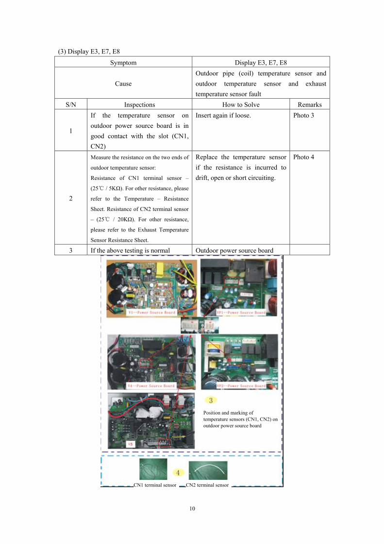
(3) Display E3, E7, E8
Symptom Display E3, E7, E8
Cause Outdoor pipe (coil) temperature sensor and outdoor temperature sensor and exhaust temperature sensor fault
S/N Inspections How to Solve Remarks
1
If the temperature sensor on outdoor power source board is in good contact with the slot (CN1, CN2)
Insert again if loose. Photo 3
2
Measure the resistance on the two ends of
outdoor temperature sensor:
Resistance of CN1 terminal sensor –
(25 / 5KΩ). For other resistance, please
refer to the Temperature – Resistance
Sheet. Resistance of CN2 terminal sensor
– (25 / 20KΩ). For other resistance,
please refer to the Exhaust Temperature
Sensor Resistance Sheet.
Replace the temperature sensor if the resistance is incurred to drift, open or short circuiting.
Photo 4
3 If the above testing is normal Outdoor power source board
Position and marking of temperature sensors (CN1, CN2) on outdoor power source board
CN1 terminal sensor CN2 terminal sensor

11
(4) Display E4
Symptom Display E4
Cause
System abnormal: Let the compressor run for 5 minutes. If the indoor coil temperature cannot be 2 lower than that before the compressor is
started (2 higher for heating mode), it can be
judged that the system is abnormal. S/N Inspections How to Solve Remarks
1 Check the high-pressure and low-pressure valves.
If not open, open again to ensure the system circulation is smooth.
Photo 5
2
Check the system refrigerant (Start and run under cooling mode. When the compressor is started, check the outlet temperature for its change. If the change is not obvious after 5 minutes)
The system is in shortage of refrigerant. Test with pressure gauge, check the leakage point and recharge the refrigerant.
Photo 6
3
Check the evaporator coil temperature sensor (25 /5KΩ).
For other resistance, please refer to the Temperature – Resistance Sheet.
Replace the temperature sensor if the resistance is incurred to drift, open or short circuiting.
Photo 7
1. The flow might be uneven for indoor system. Short circuit JP4 jumper of the indoor control board to shield this protection function (V1 – Indoor Main PCB).
Photo 8
2. The flow might be uneven for indoor system. Dial the JP4 switch of the outdoor power source board to position “1” to shield this protection function (V4 – Power Source Board).
Photo 9 4 The above inspections are normal
Replace the indoor main PCB if the problem cannot be solved by using the above methods.

12

13
(5) Display EC Symptom Display EC
Cause Outdoor communication fault between power source board and intelligent power module
S/N Inspections How to Solve Remarks
1 Check the contact of communication wire (CN5) between power source board and intelligent power module
Insert again if loose. Yellow-line part
The indicator on power source board blinks normal (bright for 1 second and dark for 1 second), but the indicator on intelligent power module does not work normally
Replace the intelligent power module
If the fault remains unsolved, replace the power source board again.
Red-line part
The indicator on intelligent power module blinks normal (bright for 1 second and dark for 1 second), but the indicator on power source board does not work normally
Replace the power source board
If the fault remains unsolved, replace the intelligent power module again.
Orange-line part
2
After the complete unit is energized, check the indicators on outdoor power source board and intelligent power module
VP1 Replace power source board
If the fault remains unsolved, replace the intelligent power module again.
CN5 position and marking

14
(6) Display EP
Symptom Display EP
Cause Temperature switch fault ( on top of the compressor)
S/N Inspections How to Solve Remarks Check the insert position CN3 of the compressor top temperature switch wires on outdoor power source board
Insert again if loose. Photo 10
1
No switch on compressor top Jumper short-circuiting (This function not provided for 1 – 1.5P unit)
Check the U, V and W wires of the compressor.
The correct sequence of U. V and W wiring shall be “red, white and blue”. Connect again if incorrect.
Photo 11
Check the system pressure.
The pressure is low. Add refrigerant to ensure the system pressure is normal.
Photo 12
2
Compressor temperature. The temperature is very high, accompanied with bad smell.
Check the outdoor ventilation and if there is any obstruction that affects the normal radiating of the air conditioner.
Install to the position as required in the Instruction Manual and ensure the air inlet and outlet of the outdoor unit is smooth.
If the fault is solved after short circuiting, replace the shell temperature switch.
3 Compressor temperature: The temperature is not high. Short circuit CN3.
If the fault remains unsolved after replacing the shell temperature switch, please replace the outdoor power source board.

15
1 – 1.5P CN3 jumper. The jumper may
be used as alternative if there is no
compressor top switch.
The correct sequence of U. V and W wiring shall be
“red, white and blue”

16
(7) Display EA
Symptom Display EA Cause Current sensor fault
S/N Inspections How to Solve Remarks
1 Check for refrigerant leakage Find the leakage point and recharge the refrigerant
If higher than 0.4V, replace the intelligent power module Photo 13
2 V1 inverter unit : Test the voltage of 5# pin to 2# pin on power factor correction
If not higher than 0.4V, replace power factor correction
3 V2、V3、V4、V5、VP1、VP2 inverter unit
Replace the outdoor power source board

17
(8) Display EU
Symptom Display EU Cause Voltage sensor fault
S/N Inspections How to Solve Remarks Insert again if loose. Photo 14
If the fault remains unsolved after connection again, please replace the outdoor power source board.
1
V1 inverter unit: Communication wires between outdoor power source board and intelligent power module (CN5)
If the fault remains unsolved after replacement of outdoor power source board, please replace the intelligent power module.
2 V2、V3、V4、V5、VP1、VP2 Inverter Unit
Replace the outdoor power source board
Check CN5 insert.

18
(9) Display E9 (Firstly display P0 or P9, then change to E9)
Symptom Display E9 (Firstly display P0 or P9, then
change to E9)
Cause Intelligent power module of drive and module
fault S/N Inspections How to Solve Remarks
If this code is displayed when the compressor is
started for several seconds or even not started,
check the compressor connection for
correctness
If no insert wrong, replace the
intelligent power module Photo 15
Check if the outdoor
module is tightly installed
onto the radiating fins and
if the silicone is applied
evenly
Fix the screws again if loose. Photo 16
Check the system
pressure.
Recharge refrigerant if the pressure
is low. Discharge some refrigerant if
the pressure is too high.
Check the outdoor
ventilation and if there is
any obstruction that
affects the normal
radiating of the air
conditioner.
Install to the position as required in
the Instruction Manual and ensure
the air inlet and outlet of the outdoor
unit is smooth.
1
Re-energize
and check the
protection
code on
display.
Firstly
display P0
“P0” appears
when the air
conditioner is
working
The above inspections are
normal, but the fault
remains unsolved
Replace the intelligent power
module
If this code is displayed when the compressor is
started for several seconds or even not started,
check the compressor connection for
correctness
If no insert wrong, replace the
intelligent power module
Cooling / heating is
normal during run
Replace the intelligent power
module
P9 appears after
the air conditioner
is started and has
run for a period of
time
If the cooling / heating is
abnormal, check the
compressor wiring for
correctness.
Insert again if loose.
Be sure to apply
silicone when
replacing
intelligent
power module.
2
Re-energize
and check the
protection
code on
display.
Firstly
display P9
When the compressor is restarted immediately
after stop, this might also cause P9 protection
because the cooling system is not stable.
Try starting the air conditioner again
after a longer period of stop

19
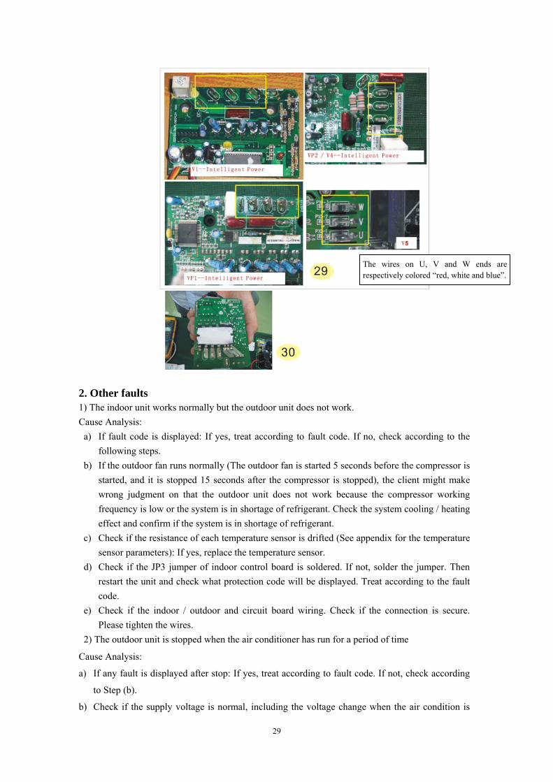
The wires on U, V and W ends are
respectively colored “red, white and blue”.
Apply the silicone evenly.
If the screw is not fixed
tightly to position, it is easy
to cause poor radiation and
damage to the elements.

20
(10) Display E0、E5
Symptom Display E0、E5 Cause Indoor / outdoor communication fault
S/N Inspections How to Solve Remarks 1. Check if the indoor and outdoor connections are correct.
The terminal L and N shall correspond to each other on
indoor and outdoor units. Measure the voltage on outdoor
terminal L and N (before display of E0 fault). If the voltage
is “0”:
Replace the indoor control board. Photo 17
(red)
2. If the L & N voltage is normal, measure the voltage
between the outdoor terminal N and 1. If the voltage
change occurs between 0~24V (change pulse voltage)
Replace the indoor main PCB.
3. If the L & N voltage is normal, measure the voltage
between the outdoor terminal N and 1. If the voltage
change occurs between 0~12V( change pulse voltage), but
there is no 24V:
Replace the outdoor power source
board
Photo 17
(yellow)
4. If the L & N voltage is normal, measure the voltage
between the outdoor terminal N and 1. If the voltage has no
change:
Firstly replace the indoor main
PCB. If the fault remains unsolved,
replace the outdoor power source
board.
1) The indicator is dark: Check PFC board – Test the pins of rectifier bridge, fast recovery diode (FRD) and IGBT elements for any breakdown, short circuiting or damage.
If damaged, it is needed to replace
PFC board. Photo 17
(red)
2) If no damage, test the DC voltage between DC+ and DC-. If the voltage is approx. 300V:
Replace the power source board.
5. Indicator on outdoor power source board 3) If no damage, test the DC voltage
between DC+ and DC-. If the voltage is zero:
Replace the power factor
correction.
Photo 18
(yellow)
6. If the problem cannot be solved by using the methods above:
Firstly replace the intelligent power
module . If the problem remains
unsolved, replace the indoor main
PCB. Power source board . power
factor correction.
1
Energize
and
observe
for
approx.
10
minutes.
If E0 is
always
displayed
or
changed
to E5
after a
period of
time:
7. If this fault appears at the initial installation and testing of the complete unit, please check if the indoor control board and outdoor inverter module are of the same generation.
Replace with the same generation
of products

21
Check power factor correction– Test thepins of rectifier bridge, fast recovery diode(FRD) and IGBT elements for anybreakdown, short circuiting or damage.
Test the DC voltage between DC+ and DC-.

22
(11) Display EE
Symptom Display EE Cause EEPROM fault
S/N Inspections How to Solve Remarks
Shut down the power supply and re-energize. If the fault remains, it is needed to check if the indoor EEPROM installation is loose or improper.
Fix again Photo 19
1 Shut down the power supply and re-energize. If the fault remains, it is needed to check if the outdoor EEPROM installation is loose or improper.
Fix again Photo 20
2 If the installation is good: Replace the indoor main PCB firstly
3 If the fault remains unsolved after replacement of the indoor control board:
Outdoor power source board
EEPROM installation is
improper
EEPROM installation is
improper

23
(12) Display P0
Symptom Display P0 Cause Variable-frequency drive
Inspections How to Solve Remarks If this code is displayed when the compressor is started for several seconds or even not started, check the compressor connection for correctness.
If no insert wrong, replace the intelligent power module
Photo 22
Check if the outdoor intelligent power module is tightly installed onto the radiating fins and if the silicone is applied evenly.
Fix the radiator again if loose. Photo 23
Check the system pressure.
Recharge refrigerant if the pressure is low. Discharge some refrigerant if the pressure is too high.
Check the outdoor ventilation and if there is any obstruction that affects the normal radiating of the air conditioner.
Install to the position as required in the Instruction Manual and ensure the air inlet and outlet of the outdoor unit is smooth.
Re-energize and check the protection code on display. Firstly display P0
“P0” appears when the air conditioner is working
The above inspections are normal, but the fault remains unsolved
Replace the intelligent power module
The wires on U, V and W ends are respectively colored “red, white and blue”.
If the screw is not fixed tightly to position, it is easy to cause poor radiation and damage to the elements.

24
(13) Display P1
Symptom Display P1 Cause Overvoltage / undervoltage protection
S/N Inspections How to Solve Remarks
1 Test the supply voltage if it is between 160V ~260V(AC).
It is normal protection if exceeding this range.
2 Test if the voltage between L and N terminal of outdoor unit is within 160V~260V(AC).
It is normal protection if exceeding this range.
Photo 24
3 If the voltage is normal: Replace the outdoor power source board
(14) Display P2
Symptom Display P2 Cause Overcurrent protection
S/N Inspections How to Solve Remarks
1
Check if the outdoor fan motor is stopped due to overheat protection, or damaged, and if the fan capacitor is damaged.
Replace the damaged capacitor and the damaged outdoor fan motor.
2 power source board or intelligent power module damaged
VP1-- Replace the power source board V1-- Replace the intelligent power module. V4 and VP2-- Replace the intelligent power module.

25
(15) Display P4 Symptom Display P4
Cause Exhaust overtemperature protection S/N Inspections How to Solve Remarks
1 Check if the air inlet and outlet of outdoor unit is blocked by any obstructions.
Install to the position as required in the Instruction Manual and ensure the air inlet and outlet of the outdoor unit is smooth.
2 Check the system for shortage of refrigerant.
Add refrigerant
3 Check if the exhaust temperature sensor is drifted, short circuited or open circuited. (25 /20KΩ). For other
resistances, please refer to the Exhaust Temperature Sensor – Resistance Sheet)
Replace the exhaust temperature sensor
Photo 24
4 Control board damaged
Replace the outdoor power source boar
(16) Display P5 Symptom Display P5
Cause Subcooling protection under cooling mode S/N Inspections How to Solve Remarks
1 Check if the air inlet and outlet of indoor unit is blocked by any obstructions.
Install to the position as required in the Instruction Manual and ensure the air inlet and outlet of the outdoor unit is smooth.
2 Check the system for shortage of refrigerant.
Add refrigerant
3
Check if the exhaust temperature sensor is drifted, short circuited or open circuited. (Measure the resistance of the resistors on two ends of indoor temperature sensor: (25 / 5KΩ). For
other resistances, please refer to the Temperature – Resistance Sheet (Appendix 1).
Replace room temperature sensor (IRT) and Indoor pipe (coil) temperature sensor (IPT)
Photo 25
4 Control board damaged Replace the indoor control board
24

26
(17) Display P6
Symptom Display P6 Cause Overheating protection under cooling mode
S/N Inspections How to Solve Remarks1 Check if the air inlet and outlet of
outdoor unit is blocked by any obstructions.
Install to the position as required in the Instruction Manual and ensure the air inlet and outlet of the outdoor unit is smooth.
2 Check the system for shortage of refrigerant.
Add refrigerant
3 Check if the outdoor evaporator coil temperature sensor is drifted, short circuited or open circuited (25 /5KΩ).
For other resistance, please refer to the Temperature – Resistance Sheet.
Replace the outdoor coil temperature sensor
Photo 26
4 Control board damaged Replace the outdoor power source board
25
26

27
(18) Display P7 Symptom Display P7
Cause Overheating protection under heating mode S/N Inspections How to Solve Remarks
1
Check if the air inlet and outlet of outdoor unit is blocked by any obstructions.
Install to the position as required in the Instruction Manual and ensure the air inlet and outlet of the outdoor unit is smooth.
2 Check the system for shortage of refrigerant.
Add refrigerant
3
Check if the exhaust temperature sensor is drifted, short circuited or open circuited. (Measure the resistance of the resistors on two ends of indoor temperature sensor: (25 / 5KΩ). For
other resistances, please refer to the Temperature – Resistance Sheet (Appendix 1).
Replace the Room temperature sensor(IRT) and Indoor pipe(coil) temperature sensor(IPT)
Photo 27
4 Control board damaged Replace the indoor control board
(19) Display P8
Symptom Display P8 Cause Outdoor overtemperature / undertemperature
protection S/N Inspections How to Solve Remarks
1
The compressor cannot run under cooling mode when the outdoor temperature is lower than -1 , or run
under heating mode when the outdoor temperature is higher than 33 , whilst
the compressor alarms P8 protection.
Normal protection function
2
If the temperature is not within the protective range above, please refer to the Temperature – Resistance Sheet (See Appendix). Use the multimeter to measure the resistors on the two ends of outdoor intake temperature sensor (CN1) (25 /5KΩ). For other
resistance, please refer to the Temperature – Resistance Sheet.
Replace the sensor if it is incurred to drift, open circuiting or short circuiting.
Photo 28
3 If the fault remains unsolved after replacement of the sensor
Replace the outdoor power source board
27

28
(20) Display P9
Symptom Display E9 (Firstly display P0 or P9, then change to E9)
Cause Intelligent power module of drive and module fault
S/N Inspections How to Solve RemarksIf this code is displayed when the compressor is started for several seconds or even not started, check the compressor connection for correctness.
If no insert wrong, replace the intelligent power module.
Photo 29
Cooling/heating is normal during run
Replace the intelligent power module.(Be sure to apply silicone when replacing the intelligent power module.).
Photo 30
P9 appears after the air conditioner is started and has run for a period of time
If the cooling / heating are abnormal, check the compressor wiring for correctness.
Insert again if loose
1
Re-energize and check the protection code on display. Firstly display P9
When the compressor is restarted immediately after stop, this might also cause P9 protection because the cooling system is not stable.
Try starting the air conditioner again after a longer period of stop
28
29
2. Other faults 1) The indoor unit works normally but the outdoor unit does not work. Cause Analysis:
a) If fault code is displayed: If yes, treat according to fault code. If no, check according to the following steps.
b) If the outdoor fan runs normally (The outdoor fan is started 5 seconds before the compressor is started, and it is stopped 15 seconds after the compressor is stopped), the client might make wrong judgment on that the outdoor unit does not work because the compressor working frequency is low or the system is in shortage of refrigerant. Check the system cooling / heating effect and confirm if the system is in shortage of refrigerant.
c) Check if the resistance of each temperature sensor is drifted (See appendix for the temperature sensor parameters): If yes, replace the temperature sensor.
d) Check if the JP3 jumper of indoor control board is soldered. If not, solder the jumper. Then restart the unit and check what protection code will be displayed. Treat according to the fault code.
e) Check if the indoor / outdoor and circuit board wiring. Check if the connection is secure. Please tighten the wires.
2) The outdoor unit is stopped when the air conditioner has run for a period of time
Cause Analysis:
a) If any fault is displayed after stop: If yes, treat according to fault code. If not, check according
to Step (b).
b) Check if the supply voltage is normal, including the voltage change when the air condition is
The wires on U, V and W ends are respectively colored “red, white and blue”.

30
started. If the voltage is unstable or changes too heavily, please check the power source. If no
problem, check according to Step (c).
c) Check if the temperature sensors are normal (See appendix for the temperature sensor
parameters). Check if the resistance is drifted, open circuited or short circuited. If yes, replace
the sensor. If normal, check according to Step (d).
d) Check if the indoor / outdoor circuit connection and power connection are in good contact. If no,
tighten the connection wires. If yes, check according to Step (e).
e) Check if the JP3 jumper of indoor control board is soldered. If not, solder the jumper. Then
restart the unit and check what protection code will be displayed. Treat according to the fault
code.
f) Check if the refrigerant is too much or too less. If yes, add refrigerant.
3) The air conditioner is tripped when it is started.
Cause Analysis:
a) Check if the user's power source plug is correctly connected (for example, the ground wire
might be wrongly connected as the neutral wire)
b) Check if the indoor / outdoor circuit and the wiring terminal are correctly connected, and if
there is short circuiting.
c) Check if the outdoor circuit board, wiring terminal and power connection wires are damaged,
and if there is short circuiting to the metal parts.
d) Check if the rectifier bridge of outdoor controller (See appendix for its bridge) is short circuited
(The short circuiting of rectifier bridge will probably cause tripping error).
4) The complete unit does not work
Cause Analysis:
a) If fault code is displayed: If yes, treat according to fault code. If no, check according to Step (2).
b) Check if the power plug is electrified. If no, check the power source. If yes, check if the
controller fuse is good.. If no, replace the fuse. If yes, check according to Step (3).
c) Check if the resistance of the sensors on indoor and outdoor units is drifted. If yes, replace the
sensor. If no, check according to Step (4).
d) Check if the indoor and outdoor communication is failed. The step is same as that for check
when the indoor unit works normally but the outdoor unit does not work.

31
Appendix 1 1. Indoor main PCB:
Jumper for Function Selection
No power relay, with duplicateinsert as replacement
Jumper for Function Selection
Electric heater control relay

32
Indoor board for BL floor-standing inverter unit (display board + power drive board)
2. Outdoor power source board
V5

33
3. Power factor correction
4. Intelligent power module:

34
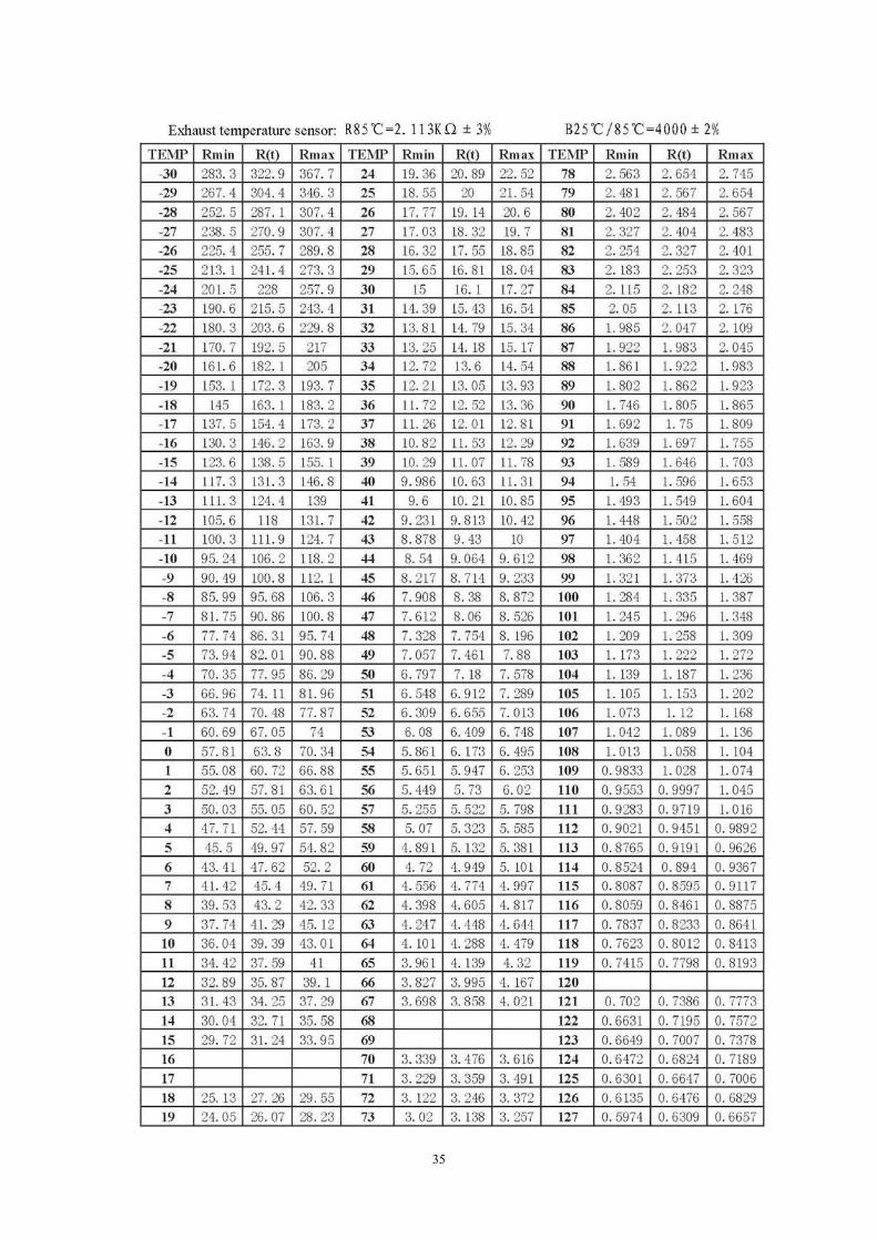
35

36
20 23.02 24.93 26.97 74 2.921 3.033 3.146 128 0.5818 0.6148 0.64921 22.04 23.84 25.77 75 2.827 2.933 3.04 129 0.5667 0.5991 0.632822 21.1 22.81 24.63 76 2.735 2.836 2.938 130 0.5521 0.5839 0.617123 20.21 21.83 23.55 77 2.647 2.743 2.84
Appendix 3
Silk-printed label on outdoor control board of inverter unit Control board connection Connector label Description label Relay label Remarks
AC power incoming wire L P1 AC-L AC power incoming wire N P2 AC-N It is required to
reserve 4 inserts at least
To indoor communication wire P3 S Ground wire P0 GND Outgoing wire L after filter P4 L K1 Relay control Outgoing wire N after filter P5 N For multiple wires,
use P5-1 and P5-2 to identify.
DC+ input P6-1 DC+ DC- input P7-1 DC- DC+ output P6-2 DC+ DC- output P7-2 DC- 4-way valve output P8 VAL K4 Outdoor fan HI output P9-1 H K2 Outdoor fan LOW output P9-2 L K3 Outdoor fan capacitor P9-3 C Compressor output phase-U P10-1 U Compressor output phase-V P10-2 V Compressor output phase-W P10-3 W Module DC+ input P6B DC+ Intelligent power
module Module DC- input P7B DC- Intelligent power
module PFC board rectified input + (Direct-insert bridge AC input)
P11 DC+ Power factor correction
PFC board rectified input - (Direct-insert bridge AC input)
P12 DC- Power factor correction
PFC inductance interface P13、P14 L Power factor correction
PFC DC+ output P6C DC+ Power factor correction
PFC DC- output P7C DC- Power factor correction
Outdoor fan DC motor socket CN9 Outdoor temperature sensor CN1 Exhaust pipe temperature sensor CN2 Suction pipe temperature sensor CN10 Compressor top thermostat CN3

37
Switching power output of power source board
CN4 CN4B on Intelligent power module, and CN4C on Power factor correction
Communication signal of power source board and module board
CN5 CN5B on Intelligent power module
Electronic expansion valve control signal
CN6 CN6B on Intelligent power module
Electronic expansion valve socket CN7 Communication between power source board and PFC board
CN9 CN9C on Power factor correction
Communication between nodule board and PFC board
CN8B(Module board)
CN8B on Power factor correction
Base Auxiliary heating CN11
Cautions on Replacement of PCB Boards 1, Directive for Replacement of Inverter Module When replacing Mitsubishi inverter module, the technician must take care on the operating process for replacement of inverter module. Special care shall be taken to ensure the coating quality of thermal grease. The detailed directive is as follows:
1. Before replacing the inverter module, make sure to eliminate the old thermal grease and
foreign particles with soft clean cloth before you can apply the new thermal grease. Always use the thermal grease provided by the customer service department or the same silicone grease as used in the factory. Never use any other product of poor quality. Operate in strict accordance with the guideline.
2. Ensure that the thermal grease (silicone grease) is applied thin, flat and even. Use plastic scraper to apply the grease. Firstly, place a tiny quantity of thermal grease at the center of the place where the grease is to be coated. Then, use the plastic scraper to apply the grease at the center slightly and evenly onto the entire surface to be treated. In consideration of the deviation in the levelness of radiating fin, the thickness of thermal grease must be 0.1mm (for small area) to 0.3mm (for large area), depending on the size of radiating area. Note: The function of thermal grease is to fill up the gap and let the surface tightly adhered. It is not true “the more the better".
3. Before placing the greased module flatly onto the radiating fin to tighten the screws, firstly hold down with the hands; then press and move back and forth slightly until it is in full contact before tightening the screws. When tightening the screws, take special care on the strength of radiator materials when using the electric screwdriver, torque screwdriver or torque wrench. Ensure that the screws are correctly tightened to position. The tightening force varies with the module.
4. Cautions on installation of screws on inverter module: If the tightening force is applied extremely unbalance`d during installation of the module onto the radiator, the silicon chip inside the module may be deformed due to the stress. And this might cause damage or degrade to the module. Therefore, be sure to operate according to the required tightening sequence.
The recommended tightening sequence for the inverter module fixed by two screws is as shown

38
below:
A\ Pre-tightening → ① ②
B\ Final tightening → ① ②
Figure Recommended Tightening Sequence for Screws
Other cautions: As the module is a precious and expensive element, never keep the new module close to magnetic object or touch the module with electrostatic object (including direct touch with your finger). Especially, touch with the port of signal terminal is easy to cause module internal breakdown and results in failure to use. If possible, you may wear electrostatic ring or glove.
2. Directive for Replacement of Power factor correction 1) Insulation paper must be attached between power diode, IGBT, rectifier and radiating fins.
The screw locking torque is 7±0.5kgf.cm. Do not loosen the insulation paper after attaching it fully flat onto the radiator. To retighten after loosening, it is needed to eliminate the aluminum scraps on the radiator before retightening.
2) It is also needed apply the thermal grease evenly when replacing and installing the PFC
with radiating substrate.
3. Directive for Replacement of Outdoor Power Source Board
1) The outdoor control is mostly the components carrying high current. The controller is
designed of partial isolation and many circuits are commonly grounded with the high current.
Take care on human safety.
Insulation paper

39
2) As the high-current circuit is close to the light-current circuit, take care on the measuring
position and safety problems during repair.
3) As there is large electrolytic capacitor on the outdoor power source board, plentiful residual
electrons shall be discharged for a period of time after the power supply is cut off. In this
case, please wait patiently until the capacitor is fully discharged before proceeding to further
operation. Full discharge may take approx. 30 seconds. You may also connect a load (e.g.
electric iron) between DC- and DC+ for manual discharge. After thorough discharge, use the
multimeter RX10K to measure. The pointer shall point to “0” position and then slowly return
to “∞”. If not, the electrolytic capacitor is damaged.
4) Make sure to have some understanding to the circuit before carrying out repair. Most
fundamentally, the operator must know the composition of the circuits, position of each part
and the possible function.
5) It is an extremely unscientific repair method for starting the measurement immediately after
getting the circuit board, or directly energizing it to start the test. This will probably cause
secondary damage to the repair board.
6) The indoor and outdoor wires must be kept in correct order. If not, it might cause failure and
damage to the electric controller. When removing the screws, take protective measures to
prevent the screws or other objects from falling down onto the circuit board or into the
electric control box. If any, be sure to eliminate them on time.