Removable appliance
63
-
Upload
ishfaq-ahmad -
Category
Health & Medicine
-
view
78 -
download
5
Transcript of Removable appliance


Presented byDr.Monwarul AzizBDS, FCPS Part II TraineeDept. of Orthodontics and Dentofacial Orthopedics, DDCH.
Supervised by
Prof. Dr. Md. Zakir HossainBDS, PhD(Japan)Prof. & Head,Dept. of Orthodontics and Dentofacial Orthopedics,DDCH.
Co SupervisorDr. Md. Muklesur Rahman (Pinu)BDS, FCPSAssociate ProfessorDept. of Orthodontics and Dentofacial Orthopedics, DDCH.
The first law of success is … concentration to
bend all the energies to one point and to go
directly to that point.
Removable mechanical appliances used to move a tooth hassame principle. Regardless of the number of trainedspecialists and the popularity of fixed appliances it seems thatmuch treatment will be carried out by general practitionerrather than specialist. Removable appliances make a valuablecontribution in orthodontic service. If used in selected caseswith perfection it gives good results.A removable appliance will only perform their taskssatisfactorily if they are worn continuously. For this not onlythe patient should be enthusiastic and co-operative but theoperator also has a duty to design and construct theappliance that they can be readily tolerated by such a patient.
Orthodontic Appliances can be Classified into:
1- Mechanical
2- functional
Mechanical appliances could be :
- Removable appliances
- Fixed appliances
Removable appliances
•Active appliances
•Retention appliances
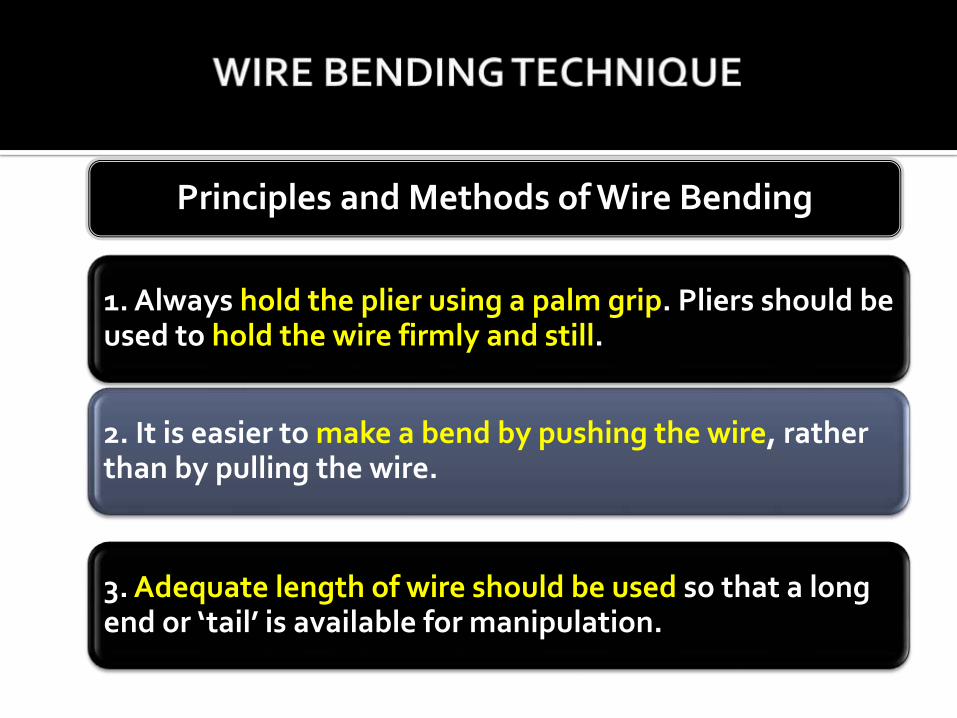
1. Always hold the plier using a palm grip. Pliers should be used to hold the wire firmly and still.
2. It is easier to make a bend by pushing the wire, rather than by pulling the wire.
3. Adequate length of wire should be used so that a long end or ‘tail’ is available for manipulation.
Principles and Methods of Wire Bending
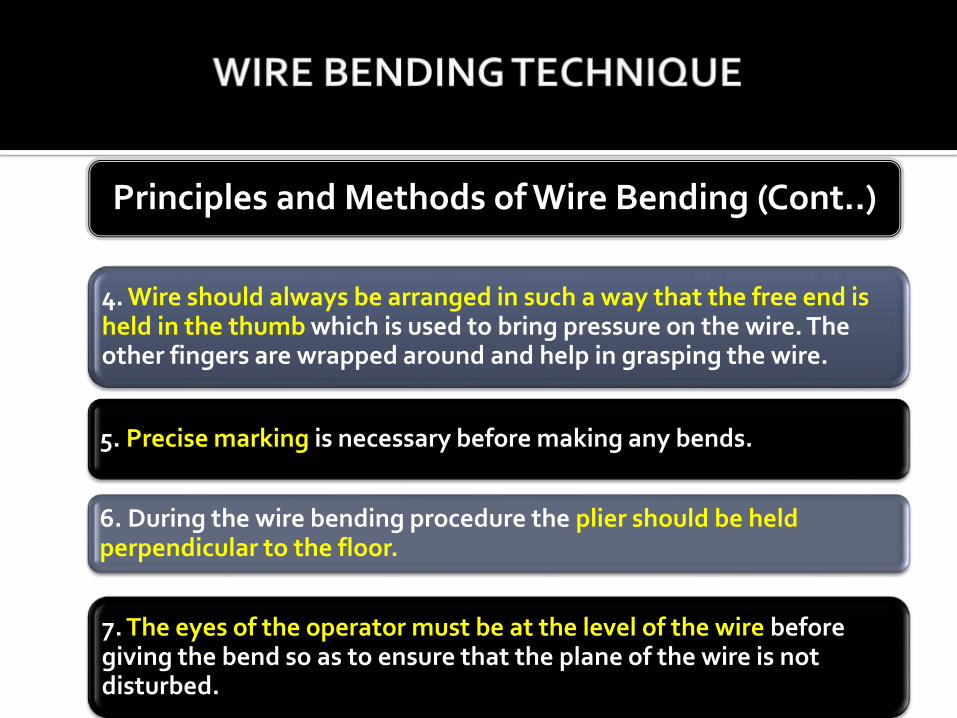
4. Wire should always be arranged in such a way that the free end is held in the thumb which is used to bring pressure on the wire. The other fingers are wrapped around and help in grasping the wire.
5. Precise marking is necessary before making any bends.
6. During the wire bending procedure the plier should be held perpendicular to the floor.
7. The eyes of the operator must be at the level of the wire before giving the bend so as to ensure that the plane of the wire is not disturbed.
Principles and Methods of Wire Bending (Cont..)
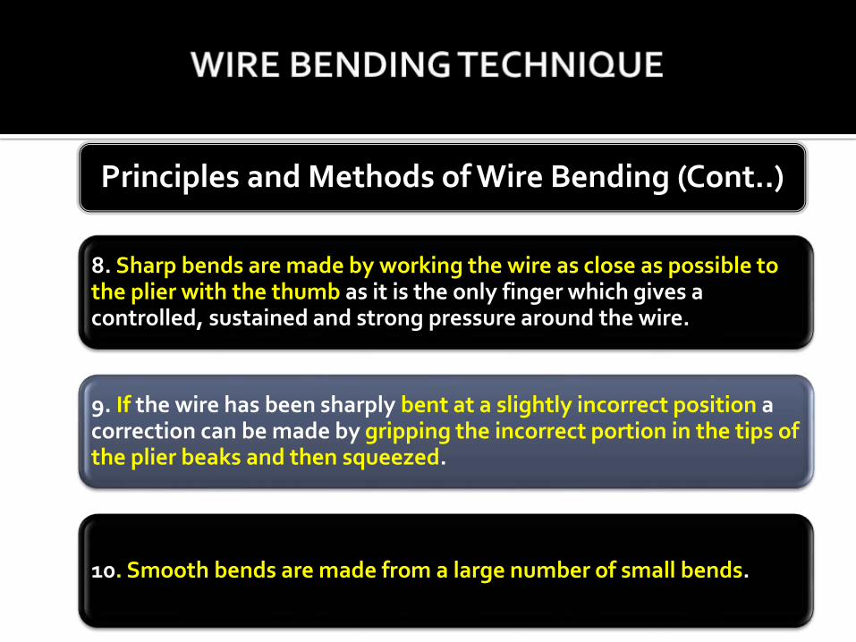
8. Sharp bends are made by working the wire as close as possible to the plier with the thumb as it is the only finger which gives a controlled, sustained and strong pressure around the wire.
9. If the wire has been sharply bent at a slightly incorrect position a correction can be made by gripping the incorrect portion in the tips of the plier beaks and then squeezed.
10. Smooth bends are made from a large number of small bends.
Principles and Methods of Wire Bending (Cont..)
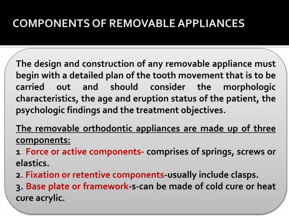
The design and construction of any removable appliance mustbegin with a detailed plan of the tooth movement that is to becarried out and should consider the morphologiccharacteristics, the age and eruption status of the patient, thepsychologic findings and the treatment objectives.
The removable orthodontic appliances are made up of threecomponents:1. Force or active components- comprises of springs, screws orelastics.2. Fixation or retentive components-usually include clasps.3. Base plate or framework-s-can be made of cold cure or heatcure acrylic.
A Hawley is a simple and robust removable wire and acrylic appliance
Purpose:A Hawley appliance may be used passively toretain teeth in their new position followingorthodontic treatment; it also might act as anactive appliance to achieve minor toothmovements. A Hawley is used for preventative,interceptive, and limited corrective orthodontics.
- Hold teeth in a new position after dentition has been orthodontically corrected.
- Prevent relapse while bone fill occurs around the roots of the moved teeth.
- Minor tipping movement of teeth mesio-distally and buccally.
Indications
- Simple to construct.
- Fabricated in lab, resulting in a reduced chair time.
- Can be removed for brushing, flossing and social reasons.
- Acrylic palate is rigid: offers significant anchorage, maintains transverse expansion.
- Allows more rapid vertical setting of teeth than vacuum-formed retainers, due to the lack of complete occlusal coverage.
- Versatile: easily modified, and can be adjusted for finishing of treatments.
- Durable: can last for several years.
Advantages
- Success depends on patient compliance.
- May be considered unaesthetic due to labial bow.
- Speech might be impaired.
- Wire crosses the occlusal plane.
Disadvantages
1. Upper labial bow
2. Adams clasps on 6I6.
3. Acrylic base
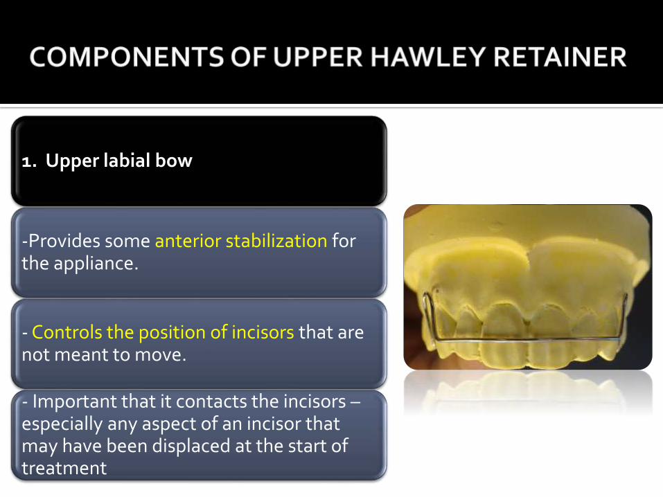
1. Upper labial bow
-Provides some anterior stabilization for the appliance.
- Controls the position of incisors that are not meant to move.
- Important that it contacts the incisors –especially any aspect of an incisor that may have been displaced at the start of treatment
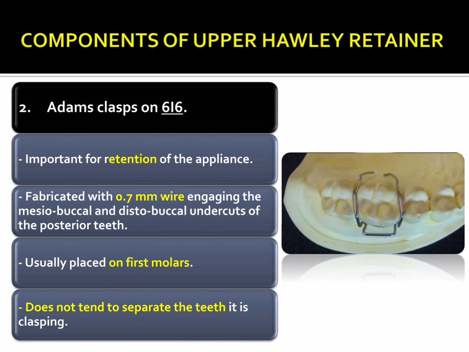
2. Adams clasps on 6I6.
- Important for retention of the appliance.
- Fabricated with 0.7 mm wire engaging the mesio-buccal and disto-buccal undercuts of the posterior teeth.
- Usually placed on first molars.
- Does not tend to separate the teeth it is clasping.
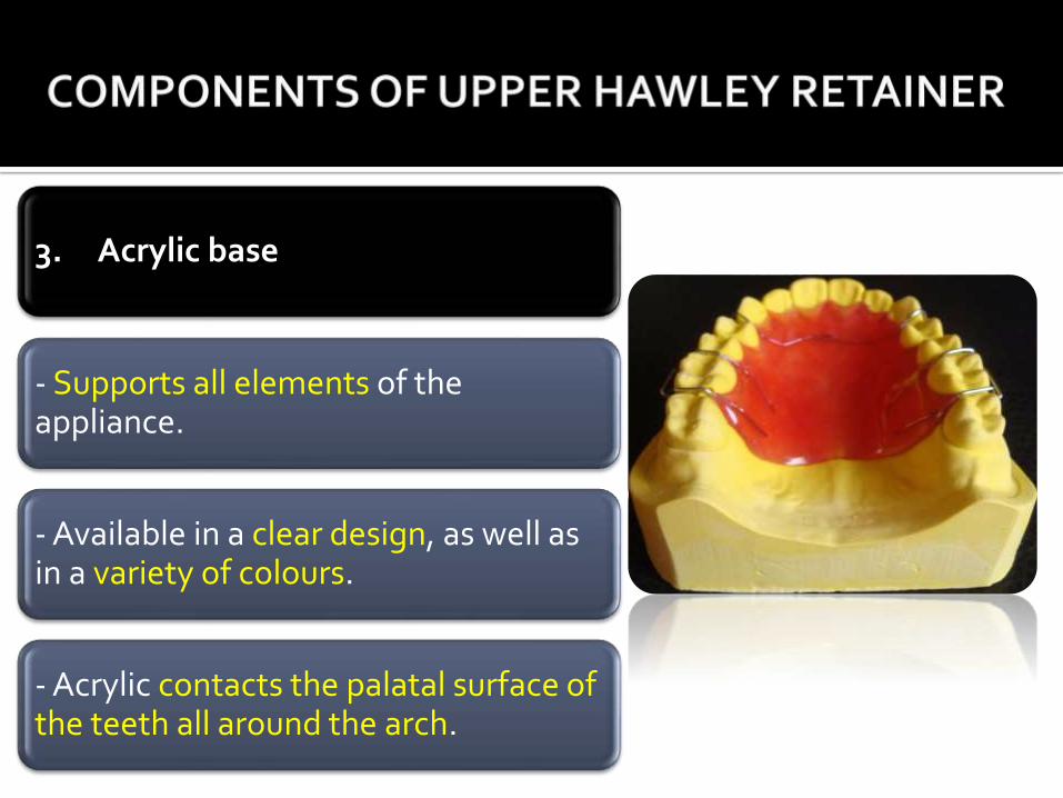
3. Acrylic base
- Supports all elements of the appliance.
- Available in a clear design, as well as in a variety of colours.
- Acrylic contacts the palatal surface of the teeth all around the arch.
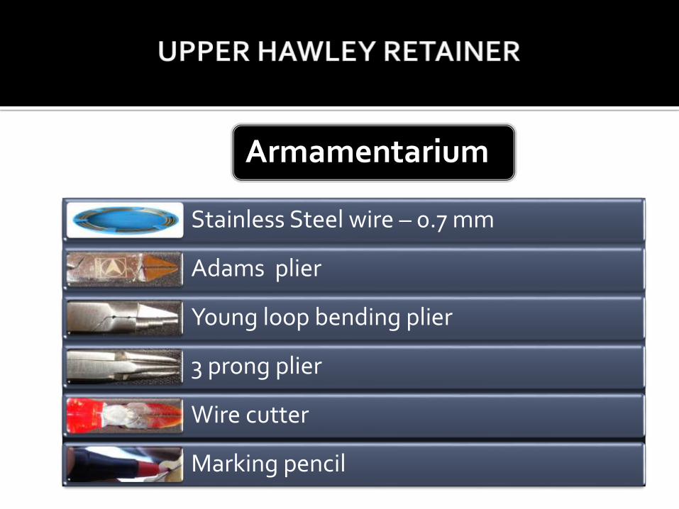
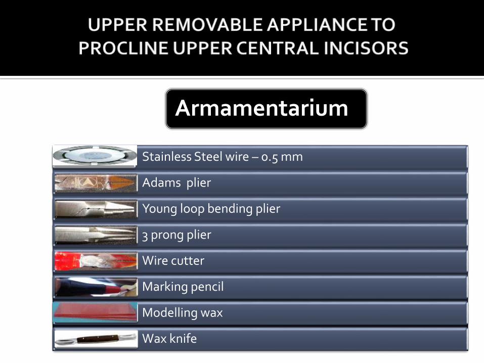
Armamentarium
Stainless Steel wire – 0.7 mm
Adams plier
Young loop bending plier
3 prong plier
Wire cutter
Marking pencil
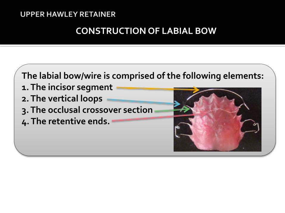
CONSTRUCTION OF LABIAL BOW
The labial bow/wire is comprised of the following elements:1. The incisor segment2. The vertical loops3. The occlusal crossover section4. The retentive ends.
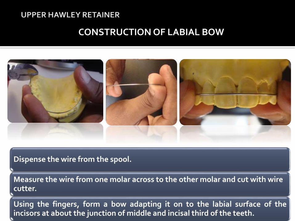
CONSTRUCTION OF LABIAL BOW
Dispense the wire from the spool.
Measure the wire from one molar across to the other molar and cut with wire cutter.
Using the fingers, form a bow adapting it on to the labial surface of theincisors at about the junction of middle and incisal third of the teeth.
CONSTRUCTION OF LABIAL BOW (Cont..)
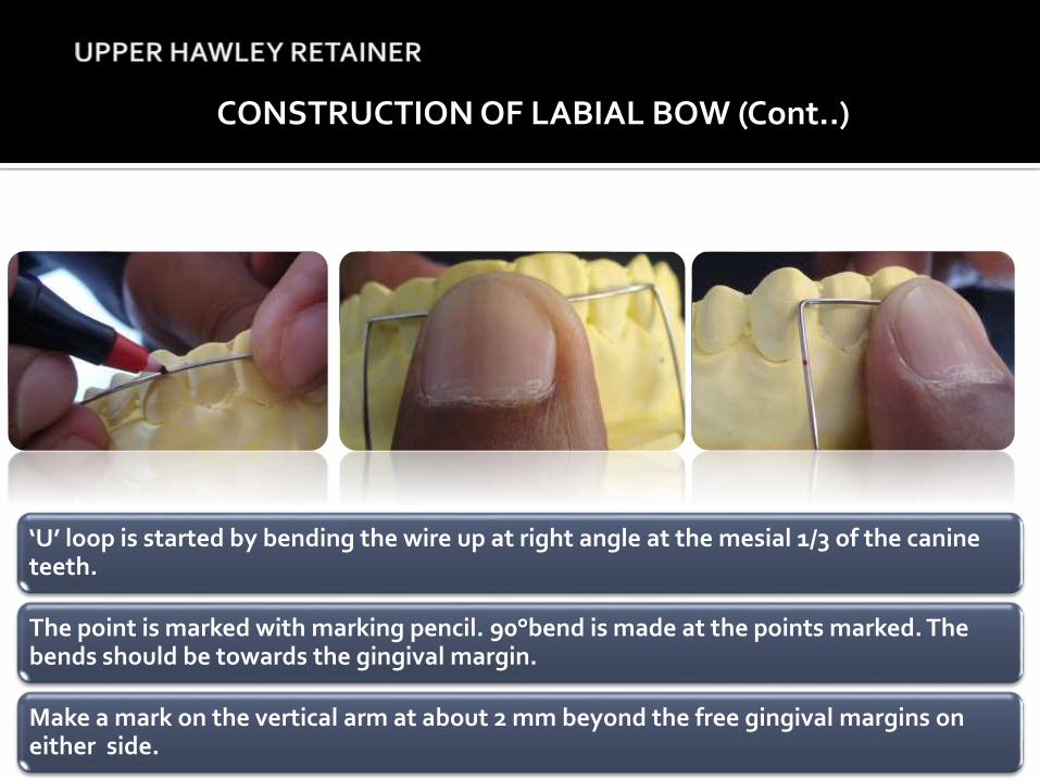
‘U’ loop is started by bending the wire up at right angle at the mesial 1/3 of the canine teeth.
The point is marked with marking pencil. 90°bend is made at the points marked. The bends should be towards the gingival margin.
Make a mark on the vertical arm at about 2 mm beyond the free gingival margins on either side.
CONSTRUCTION OF LABIAL BOW (Cont..)
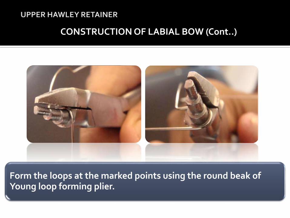
Form the loops at the marked points using the round beak of Young loop forming plier.
CONSTRUCTION OF LABIAL BOW (Cont..)
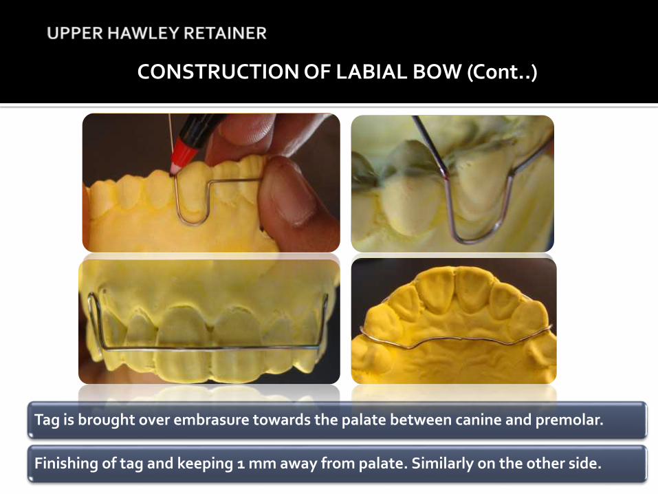
Tag is brought over embrasure towards the palate between canine and premolar.
Finishing of tag and keeping 1 mm away from palate. Similarly on the other side.
THE ADAMS CLASP
It was introduced by CP Adams in 1949.
It is a modification of Schwarz arrowhead clasp.
Most popular retentive device without which removable appliance therapy would be less successful.
It is also known as the Liverpool clasp (universal clasp) or Modified arrowhead clasp.
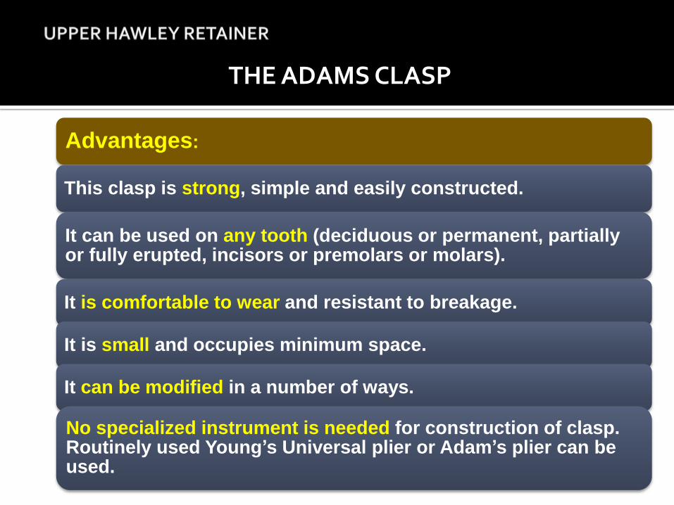
Advantages:
This clasp is strong, simple and easily constructed.
It can be used on any tooth (deciduous or permanent, partially or fully erupted, incisors or premolars or molars).
It is comfortable to wear and resistant to breakage.
It is small and occupies minimum space.
It can be modified in a number of ways.
No specialized instrument is needed for construction of clasp. Routinely used Young’s Universal plier or Adam’s plier can be used.
THE ADAMS CLASP
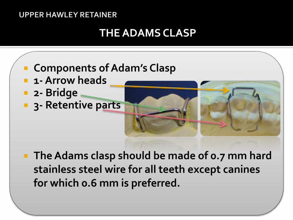
Components of Adam’s Clasp 1- Arrow heads 2- Bridge 3- Retentive parts
The Adams clasp should be made of 0.7 mm hard stainless steel wire for all teeth except canines for which 0.6 mm is preferred.
THE ADAMS CLASP
CONSTRUCTION OF THE ADAMS CLASP
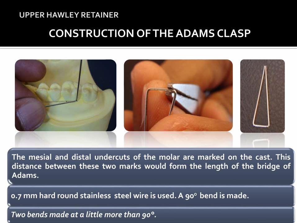
The mesial and distal undercuts of the molar are marked on the cast. Thisdistance between these two marks would form the length of the bridge ofAdams.
0.7 mm hard round stainless steel wire is used. A 900 bend is made.
Two bends made at a little more than 90°.
CONSTRUCTION OF THE ADAMS CLASP (Cont..)
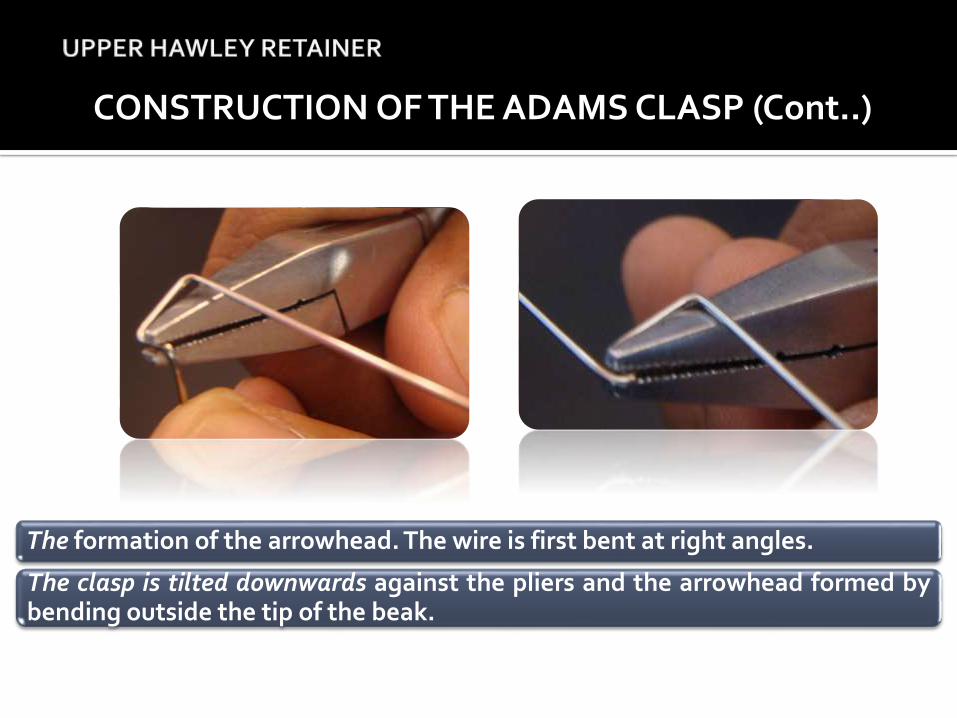
The formation of the arrowhead. The wire is first bent at right angles.
The clasp is tilted downwards against the pliers and the arrowhead formed bybending outside the tip of the beak.
CONSTRUCTION OF THE ADAMS CLASP (Cont..)
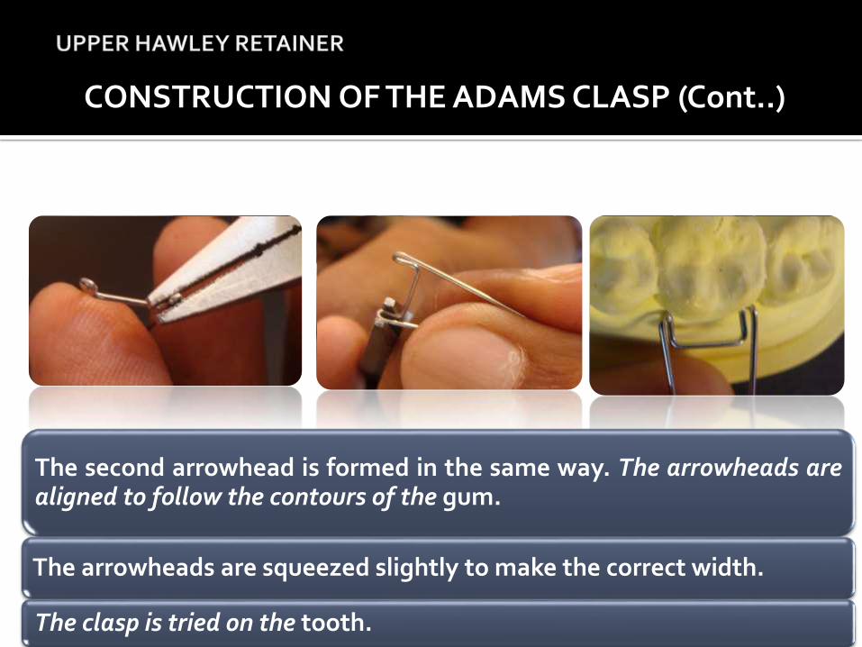
The second arrowhead is formed in the same way. The arrowheads arealigned to follow the contours of the gum.
The arrowheads are squeezed slightly to make the correct width.
The clasp is tried on the tooth.
CONSTRUCTION OF THE ADAMS CLASP (Cont..)
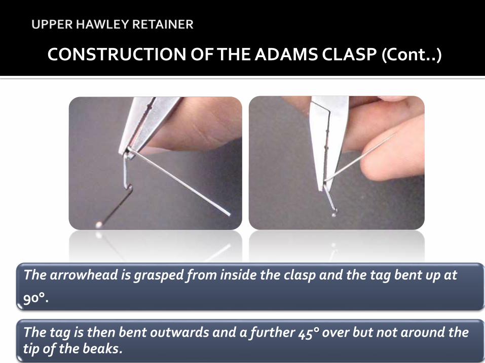
The arrowhead is grasped from inside the clasp and the tag bent up at
90°.
The tag is then bent outwards and a further 45° over but not around the tip of the beaks.
CONSTRUCTION OF THE ADAMS CLASP (Cont..)
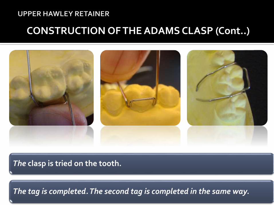
The clasp is tried on the tooth.
The tag is completed. The second tag is completed in the same way.
CONSTRUCTION OF THE ADAMS CLASP (Cont..)
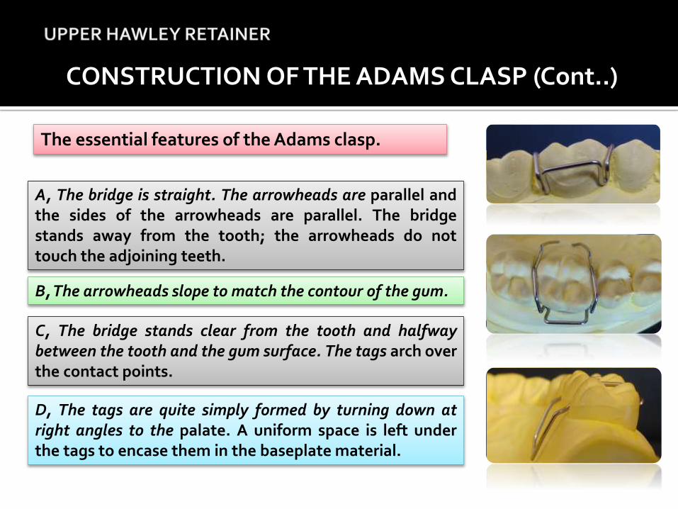
The essential features of the Adams clasp.
A, The bridge is straight. The arrowheads are parallel andthe sides of the arrowheads are parallel. The bridgestands away from the tooth; the arrowheads do nottouch the adjoining teeth.
B, The arrowheads slope to match the contour of the gum.
C, The bridge stands clear from the tooth and halfwaybetween the tooth and the gum surface. The tags arch overthe contact points.
D, The tags are quite simply formed by turning down atright angles to the palate. A uniform space is left underthe tags to encase them in the baseplate material.
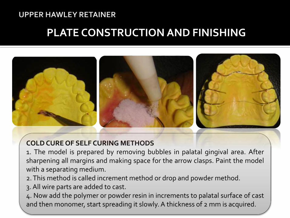
COLD CURE OF SELF CURING METHODS1. The model is prepared by removing bubbles in palatal gingival area. Aftersharpening all margins and making space for the arrow clasps. Paint the modelwith a separating medium.2. This method is called increment method or drop and powder method.3. All wire parts are added to cast.4. Now add the polymer or powder resin in increments to palatal surface of castand then monomer, start spreading it slowly. A thickness of 2 mm is acquired.
PLATE CONSTRUCTION AND FINISHING
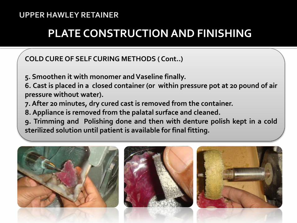
COLD CURE OF SELF CURING METHODS ( Cont..)
5. Smoothen it with monomer and Vaseline finally.6. Cast is placed in a closed container (or within pressure pot at 20 pound of airpressure without water).7. After 20 minutes, dry cured cast is removed from the container.8. Appliance is removed from the palatal surface and cleaned.9. Trimming and Polishing done and then with denture polish kept in a coldsterilized solution until patient is available for final fitting.
PLATE CONSTRUCTION AND FINISHING
Upon delivery of the appliance, the patient should be seen after:
- 1 month , - 3 months , - 6 months , - 1 year , - every year thereafter
The fit of the appliance should be checked as well as the tightness and retention. The following adjustments may be necessary:
1) Tightening of the clasps
2) Activation of the springs
3) Removal of the material from the baseplate (eg. to relieve a buried fingerspring).
Recall appointments
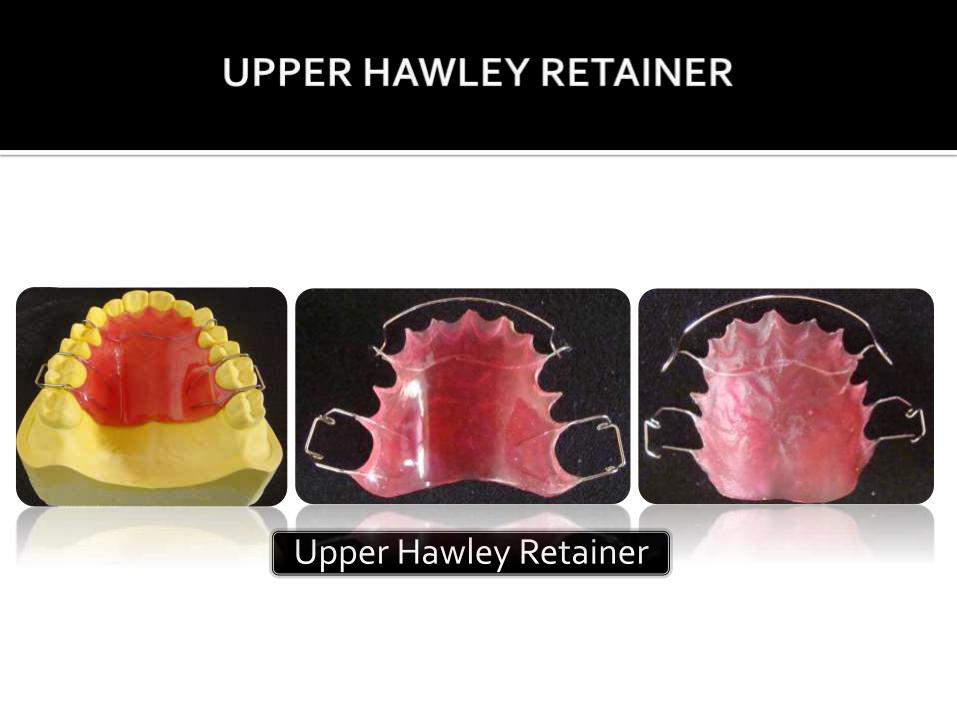
Upper Hawley Retainer
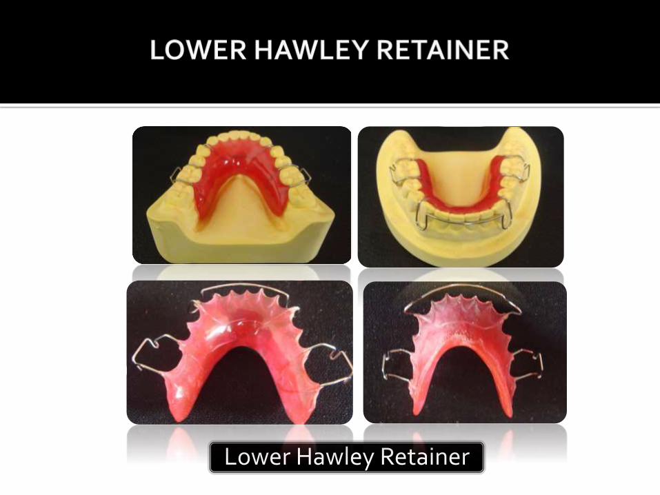
Lower Hawley Retainer


Stainless Steel wire – 0.8 mm
Adams plier
Young loop bending plier
3 prong plier
Wire cutter
Marking pencil
Armamentarium
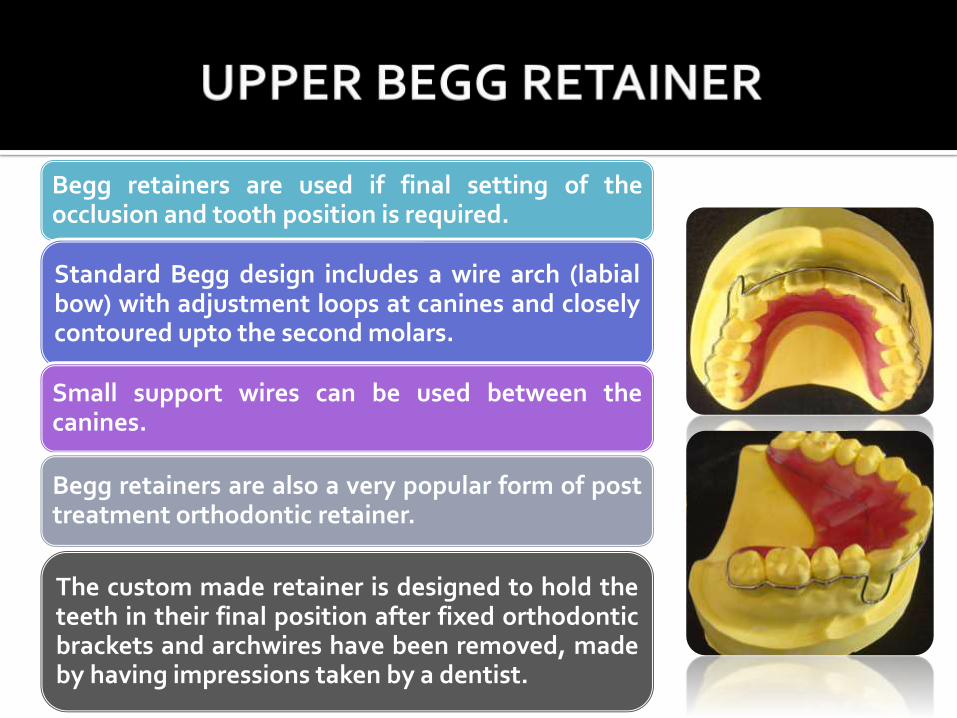
Begg retainers are used if final setting of theocclusion and tooth position is required.
Standard Begg design includes a wire arch (labialbow) with adjustment loops at canines and closelycontoured upto the second molars.
Small support wires can be used between thecanines.
Begg retainers are also a very popular form of posttreatment orthodontic retainer.
The custom made retainer is designed to hold theteeth in their final position after fixed orthodonticbrackets and archwires have been removed, madeby having impressions taken by a dentist.
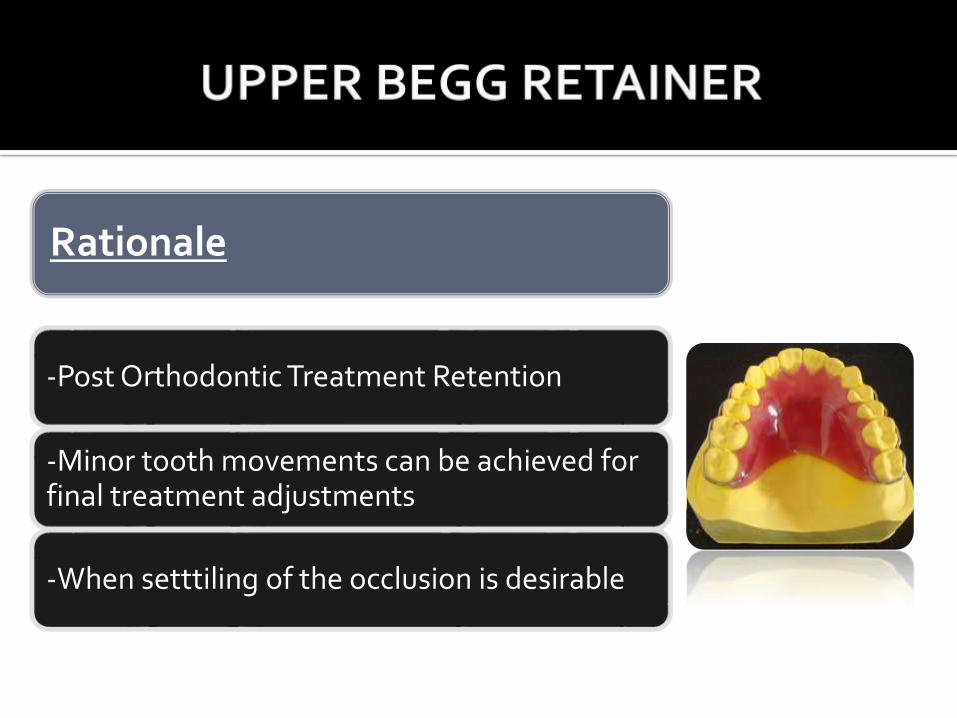
Rationale
-Post Orthodontic Treatment Retention
-Minor tooth movements can be achieved for final treatment adjustments
-When setttiling of the occlusion is desirable
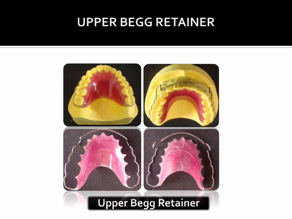
Upper Begg Retainer

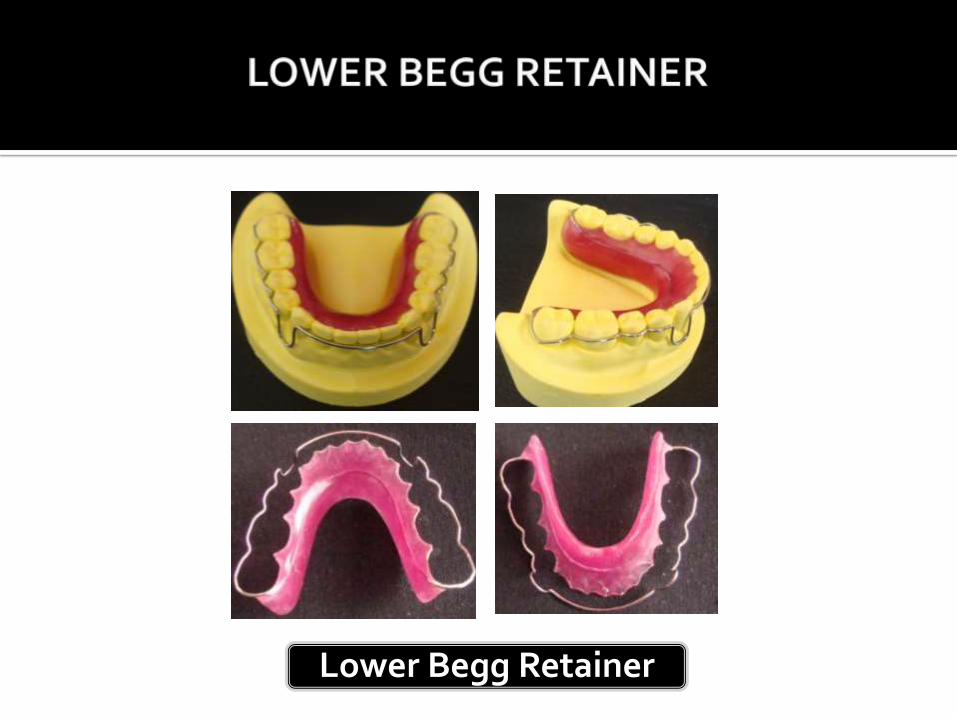
Lower Begg Retainer
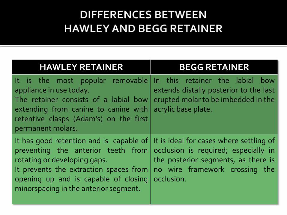
HAWLEY RETAINER BEGG RETAINER
It is the most popular removableappliance in use today.The retainer consists of a labial bowextending from canine to canine withretentive clasps (Adam's) on the firstpermanent molars.
In this retainer the labial bowextends distally posterior to the lasterupted molar to be imbedded in theacrylic base plate.
It has good retention and is capable ofpreventing the anterior teeth fromrotating or developing gaps.It prevents the extraction spaces fromopening up and is capable of closingminorspacing in the anterior segment.
It is ideal for cases where settling ofocclusion is required; especially inthe posterior segments, as there isno wire framework crossing theocclusion.
Armamentarium
Stainless Steel wire – 0.5 mm
Adams plier
Young loop bending plier
3 prong plier
Wire cutter
Marking pencil
Modelling wax
Wax knife
AdvantageSingle or two teeth are palatally placed; can be pushedlabially.
DisadvantageNot suitable for posterior teeth because it is readilytrapped on occlusal surfaces of teeth during insertion.
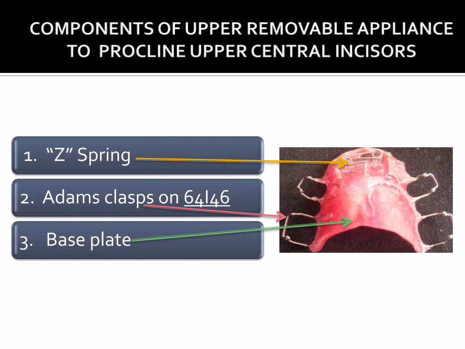
1. “Z” Spring
2. Adams clasps on 64I46
3. Base plate
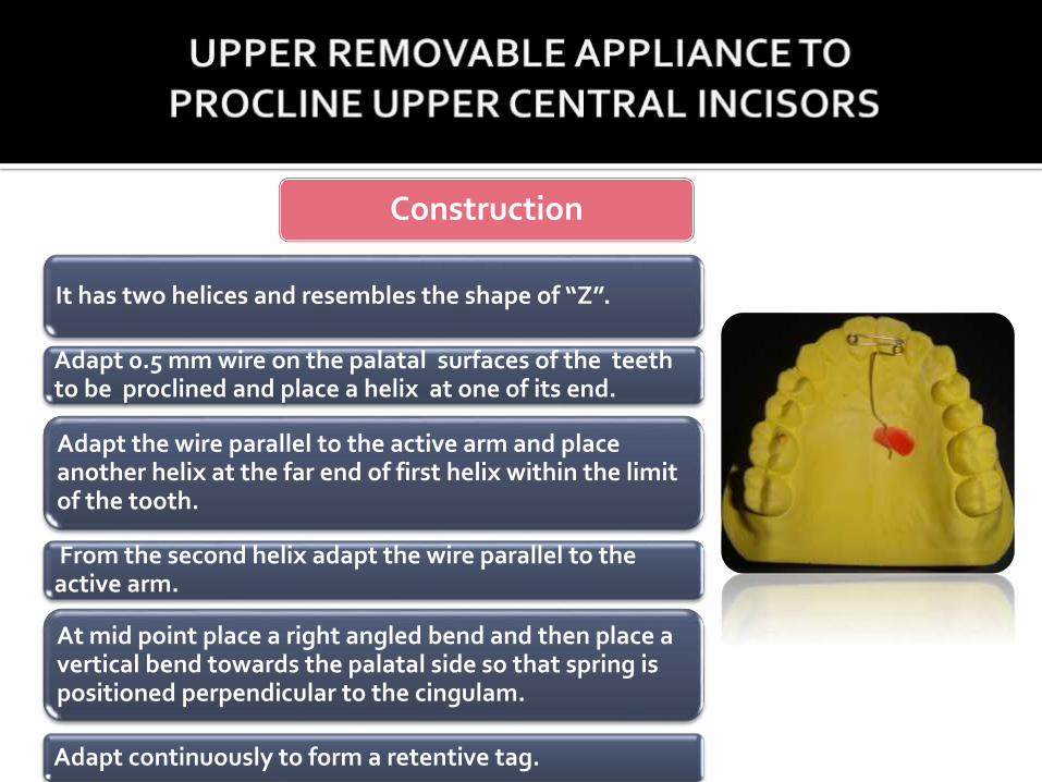
It has two helices and resembles the shape of “Z”.
Adapt 0.5 mm wire on the palatal surfaces of the teeth to be proclined and place a helix at one of its end.
Adapt the wire parallel to the active arm and place another helix at the far end of first helix within the limit of the tooth.
From the second helix adapt the wire parallel to the active arm.
At mid point place a right angled bend and then place a vertical bend towards the palatal side so that spring is positioned perpendicular to the cingulam.
Adapt continuously to form a retentive tag.
Construction
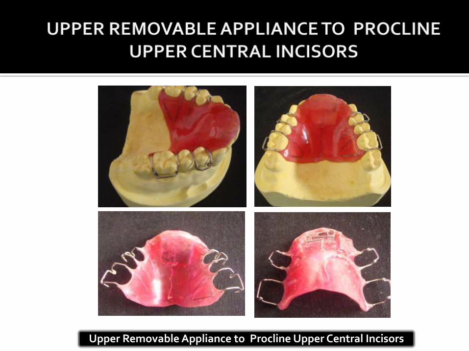
Upper Removable Appliance to Procline Upper Central Incisors

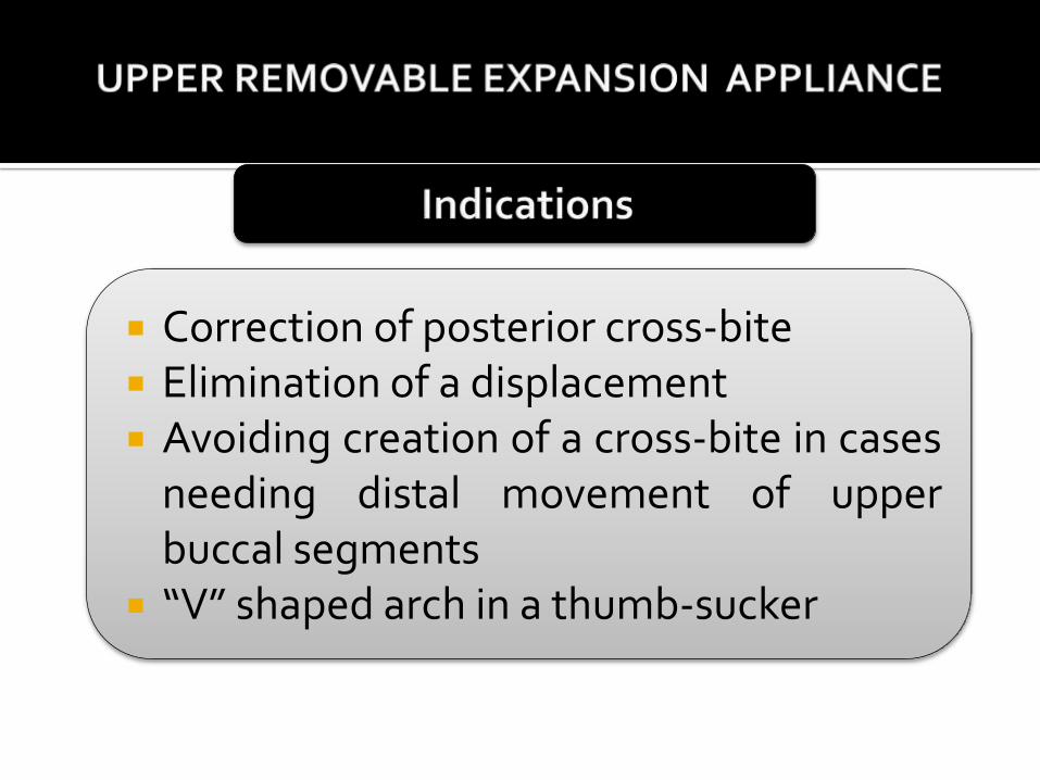
Correction of posterior cross-bite Elimination of a displacement Avoiding creation of a cross-bite in cases
needing distal movement of upperbuccal segments
“V” shaped arch in a thumb-sucker
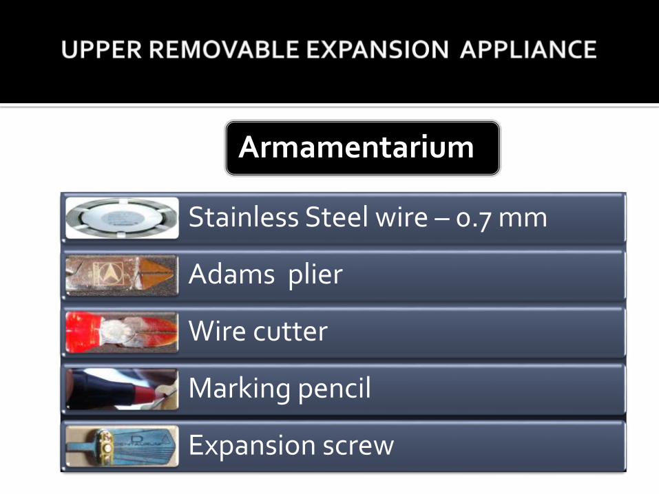
Stainless Steel wire – 0.7 mm
Adams plier
Wire cutter
Marking pencil
Expansion screw
Armamentarium
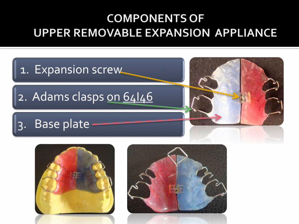
1. Expansion screw
2. Adams clasps on 64I46
3. Base plate
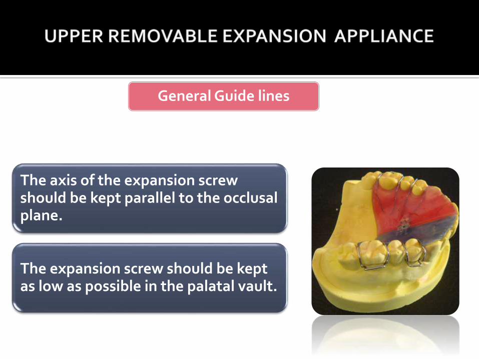
The axis of the expansion screw should be kept parallel to the occlusalplane.
The expansion screw should be kept as low as possible in the palatal vault.
General Guide lines

THANK
YOU